code of practice - awci › wp-content › uploads › cop... · code of practice for the seismic...
TRANSCRIPT

CODE OF PRACTICEfor the seismic design and installation of non-structural internal walls and partitions JULY 2018
The purpose of this Code of Practice is to assist the construction industry, building
consent authorities, architects, engineers, builders, installers and specifiers to comply
with the New Zealand Building Code.
II AWCINZ – CODE OF PRACTICE – Good practice guidelines for non-structural internal walls and partitions
Association of Wall and Ceiling Industries of New Zealand Inc.
The Association of Wall and Ceiling Industries of New Zealand Inc. is a grouping of building industry
organisations, including contractors, tradespeople, manufacturers and suppliers, established to
represent the interests of members and their customers for interior wall and ceiling lining systems and
related products.
The Association was formed in 1992 as the Interior Systems Association incorporating existing trade
groups of suspended ceilings, plasterboard and fibrous plaster. The name of the association was
changed in November 2005.
AWCINZ membership is open to any interested party.
For further information, please contact [email protected] or go to www.awcinz.org.nz.
Document historyThis document may be updated from time to time. Refer to the website www.awcinz.org.nz for the
most recent updates of this Code of Practice:
Version Date Amendments
1st published edition July 2018
Comments on this Code of Practice are welcome, please send all comments to [email protected].
The production of this Code of Practice was funded by BRANZ whose support is gratefully
acknowledged. Responsibility for the content lies solely with the Association of Wall and Ceiling
Industries of New Zealand and does not necessarily reflect the opinion of BRANZ.
ACKNOWLEDGEMENTThis Code of Practice was prepared by a project team comprising:
AWCI acknowledges the grateful assistance of the Christchurch Quake Centre and the University of
Canterbury.
John Keen – USG Boral
Nick Molcisi – Rondo
Andrew Clemmet – Potter Interior Systems
Scott McPherson – Potter Interior Systems
Scott Simpson – Tracklok
Hans Gerlich – Winstone Wallboards
Greg Preston – Quake Centre, University
of Canterbury
Sahin Tasligedik – Quake Centre, University
of Canterbury
Matt Bishop – BVT Enginnering
Phil Mowles – BRANZ
Author – Alide Elkink
Editor –
Design and layout – David Ronalds
1AWCINZ – CODE OF PRACTICE – Good practice guidelines for non-structural internal walls and partitions
Foreword
The Canterbury earthquakes of 2010-2011 and
the Wellington earthquake of 2016 highlighted
the need to consider the design and installation
of non-structural elements including internal
partitions in buildings. The collapse of non-
structural walls and partitions in an earthquake
can injure or even kill people, block escape
routes and prevent the continued use of
buildings after an earthquake.
Where non-structural partitions are damaged
but do not collapse, there is a likely loss of fire,
acoustic or thermal rating of the elements. The
loss of fire rating of internal partitions in particular
can be potentially fatal to building occupants.
This new Code of Practice focuses on the
seismic design and installation of non-structural
internal walls and partitions so that they are
able withstand light to moderate seismic
movement without experiencing significant
damage and so the building is able to have
continued functionality. It also focuses on the
roles and responsibilities of all groups involved
in the design and installation of non-structural
internal walls and partitions and the need for
coordination between all groups.
The Ministry congratulates the Association of
Wall and Ceiling Industries on its initiative in
producing this Code of Practice. It is encouraging
to see industry groups creating their own
guidance and codes of practice to complement
Ministry guidance and Acceptable Solutions
and Verification Methods. Note, however, that
this Code of Practice is not part of the Ministry’s
Acceptable Solutions, Verification Methods or
guidance documents.
Improving the compliance and performance of
non-structural internal walls and partitions will
rely on greater awareness of responsibilities for
design and installation from those involved in
the construction industry. To this end, we hope
that this Code of Practice will assist the industry
with the procurement, design and installation of
non-structural internal walls and partitions.

2 AWCINZ – CODE OF PRACTICE – Good practice guidelines for non-structural internal walls and partitions
Contents
1 Introduction 6
Background – the need for seismic solutions
for non-structural internal partitions 6
Consequences of partition failure 7
Reasons for a lack of seismic design 8
Bringing about change 8
Scope of the guidelines 8
Seismic solutions 9
Who is this GPG intended for? 9
Who is involved in the publication? 9
2 Overview of non-structural
internal partitions 10
Defining non-structural elements 10
Current methods of construction 10
Solid partition systems 10
Glazed partition systems 11
Types of seismic damage to non-structural
partitions 12
Inter-storey drift 12
Impact between elements across
movement joints 12
Impact between adjacent non-structural
elements 13
Partition failure during the New Zealand
earthquakes 13
Reasons for the lack of seismic restraint 14
Research on non-structural partition
performance during seismic events 15
Types of damage observed 15
Proposed changes to partition
installation 17
Seismic performance of glazed partitions 17
3 Statutory requirements 19
New Zealand Building Act 19
New Zealand Building Code 19
Clause B1 Structure 19
Clause B2 Durability 20
Clause C Protection from fire 20
Clause F2 Hazardous building materials 20
Acceptable solutions and verification
methods 20
Compliance with Clause B1 21
Compliance with Clause F2 21
4 Seismic design requirements for
non-structural partitions 22
Seismic separation 22
Seismic restraint requirements 25
Seismic requirements for glazed partitions 26
Summary of design considerations for
non-structural interior partitions 27
5 Design non-structural partitions
using New Zealand Standard 28
Geographic location and building type 28
Building Importance Level 28
Limit state design 29
Ultimate limit state (ULS) 30
Serviceability limit state (SLS) 30
Serviceability limit state guidelines 31
Annual probability of exceedance 31
Classification of building parts and
components 31
3AWCINZ – CODE OF PRACTICE – Good practice guidelines for non-structural internal walls and partitions
Structural design procedures in
accordance with Standards 33
Wind loads on buildings 34
Designing glazed partitions using
NZS 4223.3 34
6 An integrated approach to design 35
An integrated approach to design 35
The need for collaboration and
coordination 35
Non-structural seismic coordinator 36
Establishing design parameters 36
Construction Industry Council (CIC)
Guidelines 37
Roles and responsibilities 37
Specific roles 37
Construction monitoring 39
Producer statements 39
Procurement 40
Issues from design-build projects 40
7 Penetrations through partitions 41
Guidelines for penetrations through
partitions 41
Fire stopping materials 42
Fireboxes 43
Fire and smoke dampers 44
8 Generic details 45
Generic details and solutions 45
Partition construction 45
Improving the seismic performance of
non-structural partitions 55
9 Building Information Modelling
(BIM) 56
Overview of BIM 56
Features of BIM modelling 56
Facilitating collaboration 56
Benefits of BIM 57
BIM and non-structural partitions 57
BIM and the NZCIC Design Documentation
Guidelines 57
10 The future 58
Improved collaboration 58
Tools 58
Into the future 58
11 Appendices 59
Glossary 59

4 AWCINZ – CODE OF PRACTICE – Good practice guidelines for non-structural internal walls and partitions
List of figures
Figure 1: Cost breakdown of office buildings, hotels and hospitals 7
Figure 2: In-plane, out-of-plane and vertical deflections 14
Figure 3: Damage to conventionally-built steel and timber framed drywalls8 16
Figure 4: Glass-to-frame clearance 18
Figure 5(a): Seismic separation – partition edge 23
Figure 5(b): Seismic separation at partition head – steel channel/steelstud 23
Figure 5(c): Seismic separation at partition base – steel channel/steel stud 24
Figure 5(d): Seismic separation – vertical movement control 24
Figure 5(e): Seismic separation – vertical movement control joint 25
Figure 6: Typical layout of seismic bracing for non-structural partitions 26
Figure 7: Process for the design of a non-structural interior partition system 38
Figure 8: Clearance and fire stopping around a penetration 42
Figure 9: Typical firebox installation through FRR partition 44
Figure 10(b): Full height FRR partition base detail – steel channel/timber studs 46
Figure 10(a): Full height FRR partition head detail – steel channel/timber studs 46
Figure 11: Partial height framed partition – seismic bracing to structure 47
Figure 12(a): Full height FRR partition to underside of composite flooring 47
Figure 12(b): Full height FRR partition to underside of composite flooring – section detail 48
Figure 13: Full height FRR partition top corner detail – steel stud framing 48
Figure 14: Full height FRR partition bottom corner detail – steel stud framing 49
Figure 15: Alternative partition head details – (a) Double top track detail 49
Figure 15: Alternative partition head details – (b) Steel channel track with slotted holes for vertical and in plane movement accommodation 50
Figure 16: Corner detail – steel stud framing 50
Figure 17: Full height partition head detail – proprietary deflection track 51
Figure 18: Partition edge detail – proprietary deflection track 51
Figure 19: Glazed partition head detail – proprietary deflection track/standard aluminium glazing track 52
Figure 20: Glazed partition head detail – 50 mm aluminium glazing track 52
Figure 21: Glazed partition jamb/sill detail – proprietary deflection track/standard aluminium glazing track 53
Figure 22: Glazed partition jamb/sill detail – 50 mm aluminium glazing track 53
Figure 23: Glazed partition head detail – seismic bracing to structure/50 mm aluminium glazing track 54
Figure 24: Steel frame/plasterboard lined partition/glazed partition junction 54

5AWCINZ – CODE OF PRACTICE – Good practice guidelines for non-structural internal walls and partitions
Table 1: Determining building information from AS/NZS 1170.0 and NZS 1170.5 29
Table 2: Description and examples of building importance levels (from AS/NZS 1170.0: 2002, Tables 3.1 and 3.2). 30
Table 3: Suggested serviceability limit state criteria (from AS/NZS 1170.0: 2002, Appendix C, Table C1) 32
Table 4: Classification of building parts and components (from NZS 1170.5:2004 Table 8.1). 33
Table 5: Parties involved in stages of a building projected (adapted from CIC Guidelines (2016)). 37
Table 6: Generic stopping systems and recommended use 43
List of tables

6 AWCINZ – CODE OF PRACTICE – Good practice guidelines for non-structural internal walls and partitions
Introduction1
Background – the need for seismic solutions for non-structural internal partitions Until recently the focus of earthquake engineering
has been on the performance of the building
structure and mitigation of structural damage
to buildings but damage to non-structural
building elements and the consequences of the
damage have not been considered. However,
both the Canterbury earthquakes of 2010-13
and the Wellington earthquake in November
2016, in which a significant number of buildings
were unusable due to the damage to their
non-structural systems despite suffering little
structural damage1, highlighted the need to
consider the seismic design of non-structural
elements in buildings.
There has been a large increase in the
knowledge and understanding of seismic design
for structural systems in the past 50 years, to
the extent that modern buildings are able to
withstand the effects of moderate to severe
earthquakes and continue to perform well with
regard to building functionality and operation
and the life safety of building occupants.
At the same time, there has been little
advancement on the seismic design of non-
structural elements and almost no consideration
given to the seismic design of interior partitions
and walls. This has resulted in different levels
of serviceability of buildings following seismic
events, as was evident after both the Canterbury
and the Wellington earthquakes. Following
these earthquakes, it was found that while
the structure of buildings may have suffered
relatively low or minimal damage, the damage
to the non-structural systems, such as collapsed
ceilings, damaged partitions, fallen cupboards
and shelves, and computers and monitors
tumbling from desktops, was often sufficiently
severe to render buildings unusable.
Non-structural elements of a commercial
building typically make up between 60-80%
of the initial construction cost of the building
so damage to these elements can result in a
significant financial loss, both due the repair
costs to damaged fixtures and fittings and the
loss of revenue due to downtime to the business.
Surveys conducted following the Canterbury
and Wellington earthquakes have shown that:
y over 50% of the costs associated with the
Christchurch earthquakes, now estimated at
over $40 billion, have been attributed to non-
structural damage, and
y the damage caused to non-structural
elements in the BNZ building (constructed in
2009) in Wellington in the 2013 magnitude
6.5 earthquake, resulted in closure of the
building for 6 months, took 15 months to get
the building fully functional again and had
an estimated cost of repair of $10 million.
It sustained extensive damage again in the
2016 earthquake and at present, the building’s
future is unknown2.
Investigation into the construction cost
distribution of components for various types of
buildings (Taghavi and Miranda, 2003) shows
that the costs for non-structural components
in each of the building types is significantly
higher than for the building structure or
contents. Although these figures are from the
USA, the relative building costs in New Zealand
will be similar. The graph in Figure 1 shows
typical building construction costs for three
types of buildings. A report to the Canterbury
2 From: BVT Engineering Professional Services at: https://www.bvt.co.nz/articles/faq-seismic-restraint-of-non-structural-building-elements/
1 From: Design of low damage seismic drywalls in practical applications – Research paper by Ali Sahin Tasligedik, Ho-Hyung (Frank) Kang, Hans Gerlich, University of Canterbury Quake Centre, Christchurch, NZ.

7AWCINZ – CODE OF PRACTICE – Good practice guidelines for non-structural internal walls and partitions
Earthquakes’ Royal Commission4 estimated that
almost every building in Canterbury experienced
non-structural damage of some type during
the 2010–11 earthquakes. While the bulk of the
damage and cost of repair was to non-structural
elements such as building services (mechanical,
electrical, HVAC, sprinklers) and external
cladding systems, the Canterbury earthquakes
also resulted in significant damage to non-
structural partitions in commercial buildings.
Damage was particularly pronounced where
non-structural partitions continued past floor
levels, such as in vertical shafts and stairwells
in multi-storey buildings, but damage also
occurred to partitions fixed to the underside of
suspended ceilings and to full height partitions
that extended to the underside of the floor
above. The type of damage observed included
cracked sheet joints, crushed sheet edges,
popped fixings, and in some cases substantial
sheet fracturing and sheets that had been
dislodged from frames. The level of damage
that occurred to non-structural partitions
represented a significant economic cost.
Of additional concern was the loss of
functionality of the fire, acoustic or thermal
ratings of partitions. Fire rated partitions in
Figure 1: Cost breakdown of office buildings, hotels and hospitals
(Reference Taghavi and Miranda3)
particular must retain the rating during and
following a seismic event. For example, a partition
providing separation between an occupied space
and a safe exit route from the building is required
to be fire rated under the Building Act and the
integrity of the fire rating must be maintained.
It was observed following the earthquakes that
the level of damage that occurred to partitions
often meant they no longer had an effective fire
rating. If the partition or wall is damaged and the
fire rating compromised, the safety of building
occupants will be at risk.
Consequences of partition failure
The consequences of partition failure are
significant yet until recently, designing non-
structural partitions and walls to be able to
withstand seismic movement has not been
considered necessary. In addition to the loss
of the fire resistance rating of the partition,
partition failure can present a falling hazard or
block escape routes preventing occupants from
leaving the building.
While they are subjected to the same levels
of deflection and displacement, damage will
generally occur to non-structural building
elements at levels of building movement that
cause little damage to the building structure.5
3 Taghavi, S. & Miranda, E. (Sept 2003). Response assessment of non-structural building elements. Peer Report 2003/05, Pacific Earthquake Engineering Research Centre, College of Engineering, University of California, Berkley.
4 From Canterbury Earthqåuakes’ Royal Commission reports at: canterbury.royalcommission.govt.nz
5 Taghavi, S. & Miranda, E. (Sept 2003). Response assessment of non-structural building elements. Peer Report 2003/05, Pacific Earthquake Engineering Research Centre, College of Engineering, University of California, Berkley.
18%
0%
Hotel Hospital
62%
20%
13%
70%
17%
8%
48%
44%
Structural
Contents
Nonstructural
20%
40%
60%
80%
100%
Office
8 AWCINZ – CODE OF PRACTICE – Good practice guidelines for non-structural internal walls and partitions
This is primarily due to the lack of seismic
resistance of non-structural elements.
Non-structural partitions and walls are
typically constructed with a monolithic,
seamless and jointless finish and there are
often long lengths of walls whose surfaces
are unbroken by visible joints. This type
of construction does not allow for any
movement tolerance, particularly seismic
movement.
There are three types of potential risk from the
consequences of damage to non-structural
partitions:
y danger to life safety – there is a likelihood that
people may be injured or even killed
y property damage – as non-structural
elements including non-structural partitions
and walls account for approximately 80% of
the initial construction costs of a commercial
building, damage to non-structural elements
can be significant
y functional loss – there may be significant
post-earthquake downtime to the building
function and operations that may result in
business downtime or closure and both with a
loss of income.
Reasons for a lack of seismic design
As the non-structural elements and components
of a building are not part of the structural load
path, they have tended to be overlooked in the
building design and construction. Reasons for
this include:
y poor coordination between the different
parties involved in a building project
y poor understanding of each party’s
responsibilities
y poor procurement processes
y seismic performance and expectations for
partitions is ambiguous and undefined
y a view that partitions are someone else’s
problem
Bringing about change
There are currently no industry standards or
guidelines for the seismic performance of non-
structural interior partitioning systems. Yet the
building industry recognises that changes to
the design and installation of non-structural
internal partitions must occur. Factors that will
help bring about changes include:
y involving all groups involved in a building
project at the early stages of the project
y incorporating seismic design into all elements
and components at the design stage
y educating building practitioners on the
importance and need for seismic design of
building elements and components
y educating building owners to understand the
post-earthquake financial benefits of:
• less or no downtime due to interior building
damage
• reduced costs of reparation
• reduced insurance premiums if seismic
restraint and low-risk construction is
employed
y encouraging industry to incorporate seismic
design in non-structural building elements.
Scope of the guidelines
This Code of Practice aims to provide
standardised, industry agreed-upon solutions
for the design and installation of internal
partitions and walls that can withstand the
effects of low to moderate earthquake events
with no or minimal damage, and to:
y reduce the risk of injury caused by the failure of
interior partition systems
9AWCINZ – CODE OF PRACTICE – Good practice guidelines for non-structural internal walls and partitions
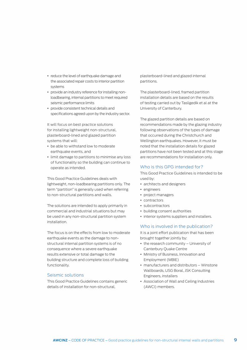
y reduce the level of earthquake damage and
the associated repair costs to interior partition
systems
y provide an industry reference for installing non-
loadbearing, internal partitions to meet required
seismic performance limits
y provide consistent technical details and
specifications agreed upon by the industry sector.
It will focus on best practice solutions
for installing lightweight non-structural,
plasterboard-lined and glazed partition
systems that will:
y be able to withstand low to moderate
earthquake events, and
y limit damage to partitions to minimise any loss
of functionality so the building can continue to
operate as intended.
This Good Practice Guidelines deals with
lightweight, non-loadbearing partitions only. The
term “partition” is generally used when referring
to non-structural partitions and walls.
The solutions are intended to apply primarily in
commercial and industrial situations but may
be used in any non-structural partition system
installation.
The focus is on the effects from low to moderate
earthquake events as the damage to non-
structural internal partition systems is of no
consequence where a severe earthquake
results extensive or total damage to the
building structure and complete loss of building
functionality.
Seismic solutions
This Good Practice Guidelines contains generic
details of installation for non-structural,
plasterboard-lined and glazed internal
partitions.
The plasterboard-lined, framed partition
installation details are based on the results
of testing carried out by Tasligedik et al at the
University of Canterbury.
The glazed partition details are based on
recommendations made by the glazing industry
following observations of the types of damage
that occurred during the Christchurch and
Wellington earthquakes. However, it must be
noted that the installation details for glazed
partitions have not been tested and at this stage
are recommendations for installation only.
Who is this GPG intended for?
This Good Practice Guidelines is intended to be
used by:
y architects and designers
y engineers
y project managers
y contractors
y subcontractors
y building consent authorities
y interior systems suppliers and installers.
Who is involved in the publication?
It is a joint effort publication that has been
brought together jointly by:
y the research community – University of
Canterbury Quake Centre
y Ministry of Business, Innovation and
Employment (MBIE)
y manufacturers and distributors – Winstone
Wallboards, USG Boral, JSK Consulting
Engineers, installers
y Association of Wall and Ceiling Industries
(AWCI) members.

10 AWCINZ – CODE OF PRACTICE – Good practice guidelines for non-structural internal walls and partitions
Overview of non-structural internal partitions
2
Internal partitions in commercial buildings are
non-structural elements that provide separations
within an occupancy or create divisions between
occupancies in the building. Most internal
partitions are non-structural, i.e. they are
lightweight, non-loadbearing elements that do not
contribute to the structural stability of the building.
Partitions between occupancies will have a fire
rating and possibly an acoustic rating, and will
be full height to the underside of the structure
above. Partitions within occupancies may or may
not have a fire or acoustic rating and often only
extend to the underside of the suspended ceiling.
As an integral part of a building fit-out,
partitions allow the layout of internal spaces
to meet the specific requirements and
configurations for the building occupants and
contribute to the overall design, appearance
and quality of the internal spaces.
Defining non-structural elements
A definition of non-structural elements, given in
the MBIE Practice Advisory 19, is:
6Non-structural elements are those elements
within a building that are not considered to
be part of either the primary or secondary
structural systems. Examples of non-structural
elements include components such as … light
non-loadbearing partitions …
NZMP 4212: 1998 Glossary of building terms
defines the terms as follows:
y an element is “Part of a building or structure
having its own functional identity.”
y a partition is “Any wall dividing a floor area. A
partition can be non-loadbearing and movable.”
y a wall is “A vertical construction 1) enclosing
a building or structure, 2) dividing the internal
space, or 3) serving as a fence.”
Current methods of construction
Non-structural partitions in commercial
buildings generally consist of either:
y a solid partition system comprising a framed
and lined construction,
y a glazed partition system, or
y a combination of the two.
Solid partition systems
Construction for framed and lined partitions
consists of either light gauge steel or timber
framing that is fully and rigidly fixed to the
building structure and lined on both sides with
a sheet lining material such as plasterboard,
plywood* or a proprietary product to create a
monolithic system.
*Note: Although other lining materials are also
used with framed and lined partition systems,
plasterboard is the most commonly used lining
material, so this Good Practice Guidelines will
refer to partitions with plasterboard lining. The
installation of partition systems with other types of
linings should use the same principles of installation.
Partition framing consists of studs running
between horizontal top and bottom plates. A
fire or acoustic-rated partition has the top plate
fixed to the underside of the structure above,
either the floor slab, the roof structure or a
structural beam. Where no rating is required,
6 From: Improving earthquake performance of non-structural elements: MBIE Practice Advisory 19 – Building Performance website at: https://www.building.govt.nz/building-code-compliance/b-stability/b1-structure/practice-advisory-19/improving-earthquake-performance-non-structural-elements/

11AWCINZ – CODE OF PRACTICE – Good practice guidelines for non-structural internal walls and partitions
the partition may extend to the underside of
the suspended ceiling only. In the past the top
plate was often fixed only to the ceiling so the
partition had no lateral stability. Top plates of
partial height partitions must be secured to the
building structure using a seismic bracing or
restraint system. There are proprietary bracing
systems available for this purpose.
Bottom plates are fixed to the floor and studs
run vertically between the top and bottom
plates at regular spacings. End wall studs are
fixed to the building structure such as a column,
an external wall or a structural return wall or
to another partition perpendicular to the stud
framing being fixed.
Steel framing is more commonly used than
timber framing for commercial construction
and particularly high-rise construction, because
of the lower weight of the framing, the ease of
construction and the stability of steel compared
to timber (i.e. timber moves significantly as a
result of changes of moisture and humidity).
Steel framing consists of roll-formed,
galvanised, 0.50 or 0.55 BMT gauge (G500
or G550), high tensile steel. It is available in
thicknesses of 0.55, 0.75, or 0.95 mm and
typical sizes are 78 or 90 mm wide by a range
of depths between 35-47 mm.
Timber framing is generally pinus radiata, either
untreated or treated to hazard class H1.2 in
accordance with NZS 3640, and available in a
range of sizes but most commonly 90 mm by
45 mm.
Sheet linings are fixed to both sides of the
framing. Standard plasterboard is generally
10 mm thick but 13 mm and thicker sheets are
available for fire and acoustic rated partitions.
Standard sheet width is 1200 mm and sheet
lengths range between 2400 to 6000 mm.
Specific use plasterboards are available for
wet areas, or fire and acoustic-rated partitions.
Additional layers of plasterboard may be
installed to one or both sides of a partition
to increase the fire and/or acoustic rating.
The acoustic rating of a partition may also be
increased by installing bulk insulating material
between the studs or by using furring channels
and resilient clips, creating a physical break
across the partition by.
The plasterboard sheets may be fixed
horizontally or vertically. Fixing is by gluing and
screwing sheets to studs and top and bottom
plates (and dwangs or nogs if used) at all
edges and across the face of the sheets. Nails
specifically designed for use with plasterboard
may be used instead of screws. The sheet
joints and fixings are plastered over to create a
monolithic appearance and the whole system is
rigidly fixed to the building structure.
Glazed partition systems
Glazed partitions are defined as either framed
or frameless systems although in both cases
aluminium framing is required to support the
panes of glass.
A framed glazed partition system generally
refers to a system where each sheet of glass is
continuously supported at all four edges, i.e with
top and bottom tracks and vertical mullions
between each pane of glass. Transoms may
sometimes be used to separate glass panes
horizontally, generally as a design feature.

12 AWCINZ – CODE OF PRACTICE – Good practice guidelines for non-structural internal walls and partitions
A frameless glazed partition system also
requires continuous top and bottom tracks to
support the glass, but vertical framing support
is at the edges of the partition only. The vertical
frames are fixed to the building structure, either
a column or a wall, or fixed to non-structural
partitions. The vertical joints between adjacent
sheets of glass are simply butted and siliconed.
Glass panes may be full height, i.e. floor-to-
ceiling, or partial height i.e. sill-to-ceiling. Glazed
partitions may be a combination of both full
height and partial height glass. The glass is
typically 6-12 mm thick and must be toughened
or laminated safety glass. It is available as clear,
tinted, or partially or fully opaque and may be
patterned in a variety of ways.
The extruded aluminium frames are available
in a wide range of profiles and finishes including
anodising and powdercoating. An anodised finish
may be coloured or left the natural silver colour of
the aluminium, while powdercoating is available in
most paint colours. The frames generally hold the
glass in place using glazing beads and gaskets, and
wedges and blocks are used to support the glass.
Glazed partitions cannot be used where a
fire-rated partition is required so they are only
full height (i.e. to the underside of the building
structure) where there is no suspended ceiling.
If an acoustic-rated glazed partition is required,
a double or ‘twin’ glazing system similar to IGU
systems, is installed.
Types of seismic damage to non-structural partitions
Non-structural building elements such as
partitions are damaged by earthquakes in a
variety of ways, including as a result of:
y building deformation causing inter-storey drift
y impact between elements across separation
or movement joints
y impact between adjacent non-structural
elements.
Inter-storey drift
During an earthquake a building is subjected
to movement in the same direction as the
ground movement. However, while the base
of a building moves with the ground there is a
delayed response higher up the building, referred
to as inertial delay. This results in different
degrees of movement going up the height of
the building relative to the movement at the
base and the ground. The effect of the inertial
delay is also amplified up the building so the
higher up the building, the greater the degree of
movement relative to the lower levels. As well as
the height of the building, other factors that may
also increase the effect of inertial delay and the
associated amplification of movement are the
building mass and the acceleration or severity of
the shaking.
The lateral or sideways movement on a building
during an earthquake causes vertical elements
such as columns and walls to be deformed
as they move slightly out of square, first in
one direction then in the opposite direction.
This movement is called inter-storey drift.
The amplification of the movement going up
the building means the amount of sideways
movement is slightly different at each floor level.
Impact between elements across movement
joints
Separation or movement joints are gaps
between different parts of the building structure
or between different buildings where they have

13AWCINZ – CODE OF PRACTICE – Good practice guidelines for non-structural internal walls and partitions
been connected internally, to allow independent
movement from one another. In an earthquake,
there is likely to be different rates of movement
of different parts or elements of the building.
If there is insufficient movement allowance,
elements are likely to impact against one
another causing them to be damaged.
In order to provide continued functionality of the
building following an earthquake, the materials
and finishes across movement joints must
be able to accommodate the same degree of
movement as the joint itself.
Impact between adjacent non-structural elements
In an earthquake, there will be different rates of
movement between adjacent non-structural
elements so if they are inadequately secured
and too close to one another, they are likely to
knock against one another and be damaged.
This was a major cause of damage to buildings
in the New Zealand earthquakes. Non-structural
elements such as services pipes and ducting
that were inadequately secured and in close
proximity, pounded against one another causing
damage to both. It was also observed that where
services pipes and ducting passed through
partitions with no allowance for movement
around the opening, the partition was also
significantly damaged.
Partition failure during the New Zealand earthquakes
The 2010/2011 earthquakes in Canterbury
and the 2013 earthquake in Wellington
highlighted the poor performance of many
non-structural internal partitions in multi-storey
commercial buildings. One of the most common
observations was that although the building
structure performed well, the non-structural
internal partitions often suffered damage
that ranged from moderate to significant and
required extensive reparation or complete
replacement.
Typical partition damage was as a result of:
y in-plane movement, i.e. movement parallel to
the wall that occurs as a result of storey drift
(Figure 2). Damage included deformation of
the framing and connection failure.
y out-of-plane movement, i.e. movement
perpendicular to the wall due to storey drift or
from floor deflections. Damage was typically
to the connections at the top of the partitions,
sometimes resulting in complete failure and
overturning of the partition. This type of failure
can endanger building occupants by causing
injury and blocking egress routes as people
attempt to leave the building.
The most significant damage occurred to
partitions with large areas of plasterboard lining
and where the linings were continuous past floor
levels such as in vertical shafts and stairwells of
multi-level buildings. Typical damage included
cracked sheet joints, crushed sheet edges,
popped fixings, fractured sheets, and sheets
that had dislodged from the framing. The levels
of damage meant that where partitions were
fire rated such as between an exitway and an
occupied space or where a pressure differential
between spaces was required to control the
movement of smoke, the fire resistance rating
and therefore the safety of building occupants
were potentially compromised.
Other types of damage that were observed
included that many partition failures occurred
due to a lack of adequate seismic restraint of
partial height partitions to the building structure.

14 AWCINZ – CODE OF PRACTICE – Good practice guidelines for non-structural internal walls and partitions
Figure 2: In-plane, out-of-plane and vertical deflections
It was noted that in even recently constructed
buildings, partial height partitions are often
installed without effective seismic restraint and
in some situations, no seismic restraint at all.
The damage that occurred highlighted the need
for adequate seismic bracing.
Partitions that supported book or storage
shelves or were used to provide lateral support
for floor-supported storage shelves, equipment
or other non-structural items, also fared
particularly badly. The design of partitions does
not generally consider the additional loads
imposed on the partitions but following the
earthquakes it was observed that partitions with
heavy fixtures attached suffered more damage
than partitions that carried no additional load.
This is because a partition supporting a load
moves at a different rate and travels a greater
distance in one direction before moving back in
the opposite direction than the same partition
without additional loading. This often results
in a greater level of damage to the partition
supporting additional loading.
Reasons for the lack of seismic restraint
While the structural engineer focuses on
the structural design of a building, the non-
structural elements such as internal partitions
are not generally included in the structural
engineer’s brief. In fact, the design and
installation of non-structural components
typically occurs after the building consent
documentation has been processed by the BCA
and is often undertaken by the system supplier
or the subcontractor.
in-plane deflection
vertical deflection
out-of-plane deflection

15AWCINZ – CODE OF PRACTICE – Good practice guidelines for non-structural internal walls and partitions
This means that the non-structural partitioning
system seldom undergoes a seismic design
review or bracing installation check. And as BCAs
do not require specific design or construction
producer statements for seismic bracing of the
non-structural partitioning systems, they are not
generally provided.
There are a number of reasons for the lack of
consideration for seismic restraint or building
movement accommodation in non-structural
partitioning, including:
y lack of understanding for the need for seismic
restraint in non-structural partitioning
y seismic performance expectations are
ambiguous or inspecified
y no engineering involvement as the structural
engineer’s responsibility is typically restricted
to the building structure with little or no
involvement in the design and monitoring of
non-structural elements
y late involvement of non-structural partition
supplier
y late selection of non-structural partition
system often not occurring until after the
building consent process has been completed
and therefore not part of the approval process
y poor communication between the designer
and the contractor
y poor tender and procurement processes,
e.g. seismic restraint may be tagged out of
a tender to allow a more competitive tender
price but if the tag is not identified as being
required, it may be omitted altogether
y when the focus is on initial capital cost not life
cycle costs, so the continued functionality of
the building after an earthquake event is not
considered
y inadequate monitoring as non-structural
partitions are typically installed later in the
building project when structural monitoring
may no longer be occurring.
y new partitioning may be installed into an
existing building without applying for a
building consent, so there may be no oversight
to ensure that adequate seismic restraint is
also installed.
Research on non-structural partition performance during seismic events
Types of damage observed
Research7 was undertaken by the University
of Canterbury on the seismic performance of
plasterboard-lined (drywall) partition systems
and the ability of the systems to withstand
movement as a result of inter-storey drift.
Testing included both timber and steel framed
systems. The research found that although both
types of framing systems suffered damage,
the responses differed between the two. It was
observed that:
y steel-framed partitions began to show signs of
failure at 0.2-0.3% drift
y timber-framed partitions began to show signs
of failure at 0.75% drift.
The types of damage observed also differed:
y Steel-framed partitions began to show signs
of cracking vertically at the plasterboard
sheet lining junctions and most of the
subsequent damage occurred along these
interfaces.
y Timber-framed partitions suffered plate
anchor failure in shear particularly at the
bottom corners, but significant shear stress
at the upper corners was also observed.
Although the partitions remained serviceable
for a longer period at relatively low levels of
inter-storey drift once the damage occurred, it
was also greater. See Figure 3.
7 Research undertaken by A.S. Tasligedik, S. Pampanin and A. Palermo for the Civil and Natural Resources Engineering Department, University of Canterbury (VEESD 2013)

16 AWCINZ – CODE OF PRACTICE – Good practice guidelines for non-structural internal walls and partitions
It was determined that the reasons for the
differences in damage between the two framing
systems was due to the different methods of
installation and fixing:
The vertical studs in steel-framed construction
are able to rotate about the screw connections
to the steel channel bottom plate. This put
additional stress along the vertical joints
between lining sheets creating displacement.
The dwangs (horizontal timber blocking
between studs) in the timber-framed
construction resulted in more rigid partitions
than with steel-framing. Deformation of the
building structure (i.e. moving out of square)
on the timber framing caused diagonal
8 Tasligedik, A.S. Pampanin, S. Palermo, A. (2013). Design of low damage seismic drywalls in practical applications. Civil and Natural Resources Engineering Department, University of Canterbury (VEESD 2013), Figure 4
Figure 3: Damage to conventionally-built steel and timber framed drywalls8
compression across the sheets causing stress
damage at the corners of the partitions.
Other types of damage were also observed
including:
y In steel framing:
• top and bottom track movement due to
inadequately secured fastening
• studs coming out of the top and/or bottom
tracks
• partitions detaching from the building
structure
y in both steel and timber framing, linings:
• cracked around openings and penetrations
• compressed where the partitions were
butted to the building structure
• cracked at the perimeters of the sheets
corner crushing of the linings
lining toe crushing by rocking of the linings sheared anchorage
As-built steel framed drywall
damage concentrated to lining interfaces
As-built framed drywall
y pronounced strut action y damage concentrated to corners y anchors rupture in shear at lower border
17AWCINZ – CODE OF PRACTICE – Good practice guidelines for non-structural internal walls and partitions
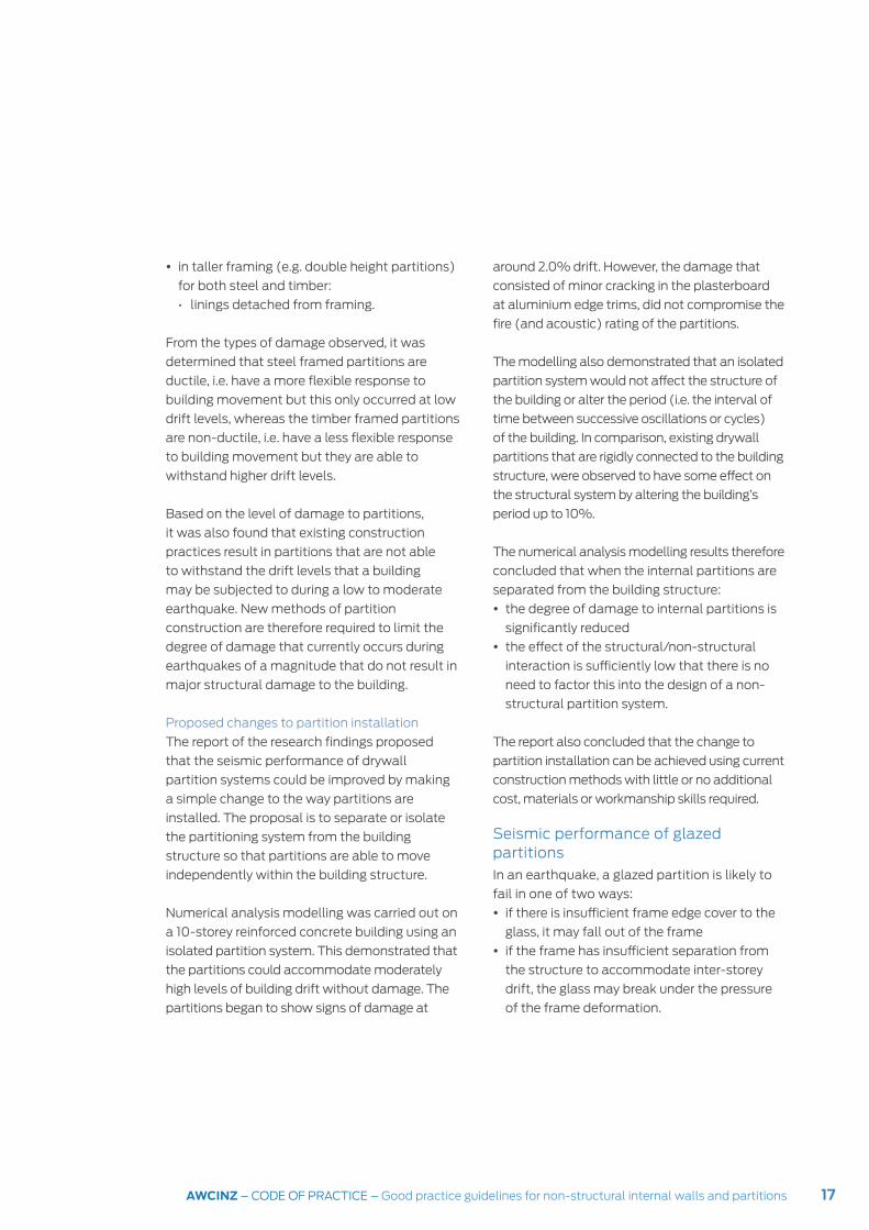
y in taller framing (e.g. double height partitions)
for both steel and timber:
• linings detached from framing.
From the types of damage observed, it was
determined that steel framed partitions are
ductile, i.e. have a more flexible response to
building movement but this only occurred at low
drift levels, whereas the timber framed partitions
are non-ductile, i.e. have a less flexible response
to building movement but they are able to
withstand higher drift levels.
Based on the level of damage to partitions,
it was also found that existing construction
practices result in partitions that are not able
to withstand the drift levels that a building
may be subjected to during a low to moderate
earthquake. New methods of partition
construction are therefore required to limit the
degree of damage that currently occurs during
earthquakes of a magnitude that do not result in
major structural damage to the building.
Proposed changes to partition installation
The report of the research findings proposed
that the seismic performance of drywall
partition systems could be improved by making
a simple change to the way partitions are
installed. The proposal is to separate or isolate
the partitioning system from the building
structure so that partitions are able to move
independently within the building structure.
Numerical analysis modelling was carried out on
a 10-storey reinforced concrete building using an
isolated partition system. This demonstrated that
the partitions could accommodate moderately
high levels of building drift without damage. The
partitions began to show signs of damage at
around 2.0% drift. However, the damage that
consisted of minor cracking in the plasterboard
at aluminium edge trims, did not compromise the
fire (and acoustic) rating of the partitions.
The modelling also demonstrated that an isolated
partition system would not affect the structure of
the building or alter the period (i.e. the interval of
time between successive oscillations or cycles)
of the building. In comparison, existing drywall
partitions that are rigidly connected to the building
structure, were observed to have some effect on
the structural system by altering the building’s
period up to 10%.
The numerical analysis modelling results therefore
concluded that when the internal partitions are
separated from the building structure:
y the degree of damage to internal partitions is
significantly reduced
y the effect of the structural/non-structural
interaction is sufficiently low that there is no
need to factor this into the design of a non-
structural partition system.
The report also concluded that the change to
partition installation can be achieved using current
construction methods with little or no additional
cost, materials or workmanship skills required.
Seismic performance of glazed partitions
In an earthquake, a glazed partition is likely to
fail in one of two ways:
y if there is insufficient frame edge cover to the
glass, it may fall out of the frame
y if the frame has insufficient separation from
the structure to accommodate inter-storey
drift, the glass may break under the pressure
of the frame deformation.
18 AWCINZ – CODE OF PRACTICE – Good practice guidelines for non-structural internal walls and partitions
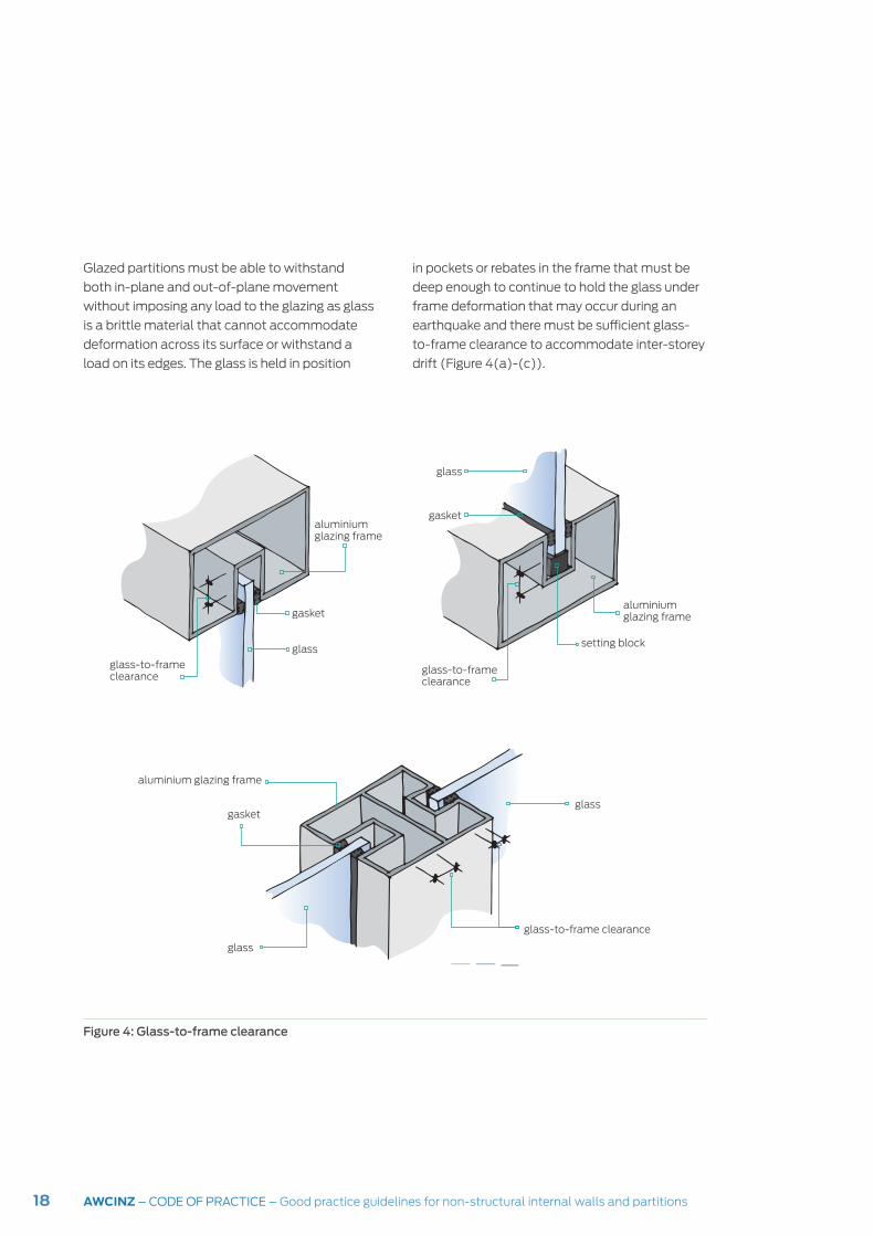
Glazed partitions must be able to withstand
both in-plane and out-of-plane movement
without imposing any load to the glazing as glass
is a brittle material that cannot accommodate
deformation across its surface or withstand a
load on its edges. The glass is held in position
Figure 4: Glass-to-frame clearance
in pockets or rebates in the frame that must be
deep enough to continue to hold the glass under
frame deformation that may occur during an
earthquake and there must be sufficient glass-
to-frame clearance to accommodate inter-storey
drift (Figure 4(a)-(c)).
aluminium glazing frame
gasket
glass
glass-to-frame clearance
glass-to-frame clearance
gasket
glass
aluminium glazing frame
setting block
glass
glass
glass-to-frame clearance
gasket
aluminium glazing frame

19AWCINZ – CODE OF PRACTICE – Good practice guidelines for non-structural internal walls and partitions
There are currently no specific statutory
requirements that apply to non-structural
internal partitions in commercial buildings and
a building consent is not required to install
non-structural partitions. Nevertheless, all
building work must comply with the Building
Act 2004 and the New Zealand Building Code
(NZBC).
New Zealand Building Act
The New Zealand Building Act 2004 defines the
rules for building work in New Zealand. It requires
that all building work complies with the New
Zealand Building Code (NZBC), even when the
work does not require a building consent. The
NZBC, contained in Schedule 1 of the Building
Regulations 1992*, sets out performance
standards for building work to meet the
requirements of the Building Act. While it sets
how a building must perform, it does not set out
how performance should be achieved, i.e. it is a
performance-based building code.
(*Note that the Building Regulations were
revoked in 2005 and Schedule 1 the only part of
the regulations that have been retained.)
The New Zealand Building Act and the New
Zealand Building Code are the mandatory
(statutory) legislative documents relating to
construction work in New Zealand.
New Zealand Building Code
The NZBC consists of three general clauses and
38 technical clauses divided into eight broad
categories of building work covering all aspects
of building work including structural stability,
fire safety, access, moisture control, durability,
services and facilities, and energy efficiency of
buildings.
3Statutory requirements
Each of the clauses consists of three
categories:
y Objectives
y Functional requirements
y Performance criteria.
If the performance criteria of a clause are met,
the objectives and functional requirements for
the clause are also met.
Not all clauses in the Building Code are relevant
to all buildings or parts of buildings. For non-
structural internal partitions the clauses that
must be considered are:
y B1 Structure
y B2 Durability
y C1-C6 Protection from fire
y F2 Hazardous building materials
Clause B1 Structure
The NZBC Clause B1 Structure:
y The objective requires buildings to be
constructed in such a way that:
• people are safeguarded from injury or loss
of amenity due to structural failure of the
building, and
• other property is not damaged as a result of
structural failure.
y The functional requirement of clause B1 states
that:
• “… building elements… shall withstand the
combination of loads that they are likely to
experience during construction or alteration
and throughout their lives”.
y The performance criteria of clause B1 require
that:
• (B1.3.1): “Building elements… shall have
a low probability of rupturing, becoming
unstable, losing equilibrium, or collapsing…
throughout their lives.”

20 AWCINZ – CODE OF PRACTICE – Good practice guidelines for non-structural internal walls and partitions
• (B1.3.2): “Building elements… shall have a
low probability of causing loss of amenity
through undue deformation, vibratory
response… throughout their lives.”
• (B1.3.3): “Account shall be taken of all
physical conditions likely to affect the
stability of … building elements including…
earthquakes…”
• (B1.3.4: “Due allowance shall be made for
(a) the consequences of failure, (b) the
intended use of the building.”
All three categories are relevant and applicable
to non-structural partitions.
Clause B2 Durability
NZBC Clause B2 Durability requires that
a building must continue to satisfy the
performance requirements of this code for
the specified intended life of the building with
only normal maintenance. For non-structural
partitions and walls, the specified intended life is
at least 5 years.
Clause C Protection from fire
Clause C Protection from fire is set out
differently from the other Building Code
clauses. It consists of six clauses, C1-C6 that
cover all aspects of building fire protection.
Clause C1 provides the objectives for each of
the C clauses. These are to:
y safeguard people from the risk of injury or
illness due to fire
y prevent fire from spreading to other properties
y facilitate firefighting.
Clauses C2-C6 deal with specific aspects of fire
safety construction based of the occupant risk
groups. Each clause is divided into parts. Part
4 – Control of internal fire and smoke spread
applies to internal partitions and walls and
includes requirements for:
y fire stopping (i.e. dealing with penetrations
through fire-rated separations),
y controlling the spread of smoke, and
y internal surface finishes of building elements.
While Clause C does not specifically apply to
mitigating seismic damage to non-structural
partitions, it does require that the fire resistance
rating of partitions is maintained for a specified
time after an earthquake event.
Clause F2 Hazardous building materials
Clause F2 Hazardous building materials requires
that potentially hazardous building materials
may only be used in such a way that they pose
no undue risk to building occupants.
This clause refers primarily to glazed partitions
and requires glazing to meet the requirements of
the referenced standards.
Acceptable solutions and verification methods
Each of the Building Code clauses contains
prescriptive solutions (acceptable solutions),
methods of testing (verification methods),
and references to New Zealand Standards and
other documentation as means of meeting the
requirements of the Code for that particular
clause of the Building Code.
When a building design that is submitted for
building consent application complies with
an acceptable solution, a verification method,
a referenced Standard or other referenced
documentation, it must be accepted by a Building
Consent Authority (BCA) as being compliant with
the relevant clause of the Building Code.
21AWCINZ – CODE OF PRACTICE – Good practice guidelines for non-structural internal walls and partitions
Compliance with the NZBC can be achieved in
a variety of ways including:
y following an acceptable solution or verification
method
y using an alternative solution,
y or using a range of other paths to demonstrate
compliance with the Building Code.
The acceptable solutions, verification methods
and other referenced material in the Building
Code are not mandatory and other means of
demonstrating compliance may also be used.
These are submitted as alternative methods of
construction and require evidence to be supplied
to the BCA to demonstrate that the proposed
alternative method will comply with the
requirements of the relevant Building Code. If an
alternative method is accepted, it will become
an alternative solution.
Most NZBC clauses provide no references or
means of compliance for non-structural interior
partitions. There are no acceptable solutions
or verification methods providing a means
of compliance for interior partitions and the
only references to New Zealand Standards
relevant to non-structural interior partitions are
contained in clauses B1 and F2.
Compliance with Clause B1
The New Zealand Standards relevant to
non-structural partitions are referenced in
Acceptable solutions and verification methods
for NZBC Clause B1 are:
y AS/NZS 1170.0 Part 0: 2002 Structural design
actions – General principles
y NZS 1170.5 Part 5: 2004 Structural design
actions – Earthquake actions – New Zealand
y NZS 4223.1 Part 1: 2008 Glazing in Buildings –
Glass selection and glazing
y NZS 4223.3 Part 3: 2016 Glazing in buildings –
Human impact safety requirements.
Verification method B1/VM1 section 2 to NZBC
Clause B1, references the AS/NZS 1170 suite of
standards generally as a means of achieving
structural compliance.
Specific references include to:
y AS/NZS 1170.0 for evaluating risk and loading
levels when designing to the ultimate and/or
serviceability limit states.
y NZS 1170.5 Section 8 for specific references
to internal, non-structural partitions. This
section addresses the requirements for parts
and components and states that all parts of
structures and non-structural components
(including partitions) and their connections
and part supports must be able to withstand
earthquake actions, deflections and
displacements.
y NZS 4223.1 for general glazing requirements
and provides the design criteria, guidance
for specific design and procedures for glass
selection, and glazing in buildings.
y NZS 4223.3 for glass design for internal
partitions, including requirements for the area
and thickness of glass, containment and edge
cover to the glass.
Compliance with Clause F2
The New Zealand Standard relevant to non-
structural partitions is referenced in Acceptable
solutions and verification methods for NZBC
Clause F2 is:
y NZS 4223.3 Part 3: 2016 Glazing in buildings –
Human impact safety requirements.

22 AWCINZ – CODE OF PRACTICE – Good practice guidelines for non-structural internal walls and partitions
Although there is no specific requirement in the
NZBC, non-structural partitions should be able to
perform at least as well as the building structure in
a low or moderate earthquake event. That is, if the
building structure is not damaged, there should be
no or minimal damage to interior partitions and
where partitions are required to be fire rated, the
fire resistance rating must be fully maintained.
Non-structural partitions and walls must be able
to resist seismic movement in all directions, both
horizontally (laterally) and vertically.
Based on both the findings from the research by
the University of Canterbury into how partition
systems responded to inter-storey drift and
observations of the seismic performance of
plasterboard-lined partition systems, two
proposals for improving the seismic resilience
of non-structural internal partitions were made.
These are for:
y seismic separation, that is isolating or
separating the non-structural partitions from
the building structure, and
y seismic bracing, that is restraint of partial
height partitions (i.e. to the underside of a
suspended ceiling) to the building structure.
If partitions are to be used to provide support or
lateral restraint to non-structural components
such as cupboards or shelving, the walls and
seismic bracing must be able to resist the
additional loading.
Seismic design and detailing for non-structural
partition installation should be included in
building consent application documentation.
4Seismic design requirements for non-structural partitions
Seismic separation
Seismic separation of non-structural partitions
from the building structure allows the
partitions to move independently, reducing
the likelihood of damage by impact from the
building structure. The seismic separation can
be achieved by providing gaps at the top and
the sides of partitions. These can be designed
as negative or shadow line details or filled
with a compressible filler material that can
accommodate seismic movement.
The amount of separation to accommodate
lateral movement is based on the calculated
inter-storey drift at the particular level of the
building. Half of the inter-storey drift should be
accommodated as a gap or seismic separation
at each end of the length of wall to avoid major
damage in the event of an earthquake.
Vertical movement allowance at the top of
plasterboard lined walls should be incorporated
to accommodate floor deflections (Figures 5(b)
and (c)).
Strips of plasterboard or a similar material
should be used as packers between all top and
side wall frame edges and the building structure.
Where partitions are required to be fire-rated,
the packing material must be plasterboard or a
proprietary fire barrier material.
Control joints are required in partitions where
there are long unbroken partitions or wall runs
and where structural control joints occur in
the primary structure. They can be achieved
by installing double studs separated by

23AWCINZ – CODE OF PRACTICE – Good practice guidelines for non-structural internal walls and partitions
Figure 5(b): Seismic separation at partition head – steel channel/steelstud
continuous plasterboard strips between perimeter track and building structure for full width of track
continuous plasterboard strips between track and underside of building structure for full width of track
10-20 mm gap – top track to underside slab/structure
expansion/seismic gap between plasterboard lining and structure as required for calculated drift
building structure
25-50 mm expansion/ movement gap
steel channel perimeter track fixed to building structure
steel studs friction fitted between top and bottom tracks
fix lining to studs only (i.e. do not fix to edge track)
plasterboard lining
Figure 5(a): Seismic separation – partition edge
steel channel top track
plasterboard lining
10-15 mm expansion gap – stud to top track
steel studs friction fitted between top and bottom tracks
underside of slab/structure above
10-15 mm gap between lining and structure
fix lining to studs only (i.e. do not fix lining to track)

24 AWCINZ – CODE OF PRACTICE – Good practice guidelines for non-structural internal walls and partitions
Figure 5(d): Seismic separation – vertical movement control
continuous plasterboard strips between studs for full depth of studs
steel studs friction fitted between top and bottom tracks
gap width as required for structural joint or partition length
steel studs friction fitted between top and bottom tracks
steel channel bottom track
fix lining to studs only (i.e. do not fix lining to track)
floor slab
Figure 5(c): Seismic separation at partition base – steel channel/steel stud
plasterboard lining
proprietary skirting fixed to studs only
plasterboard lining
25AWCINZ – CODE OF PRACTICE – Good practice guidelines for non-structural internal walls and partitions
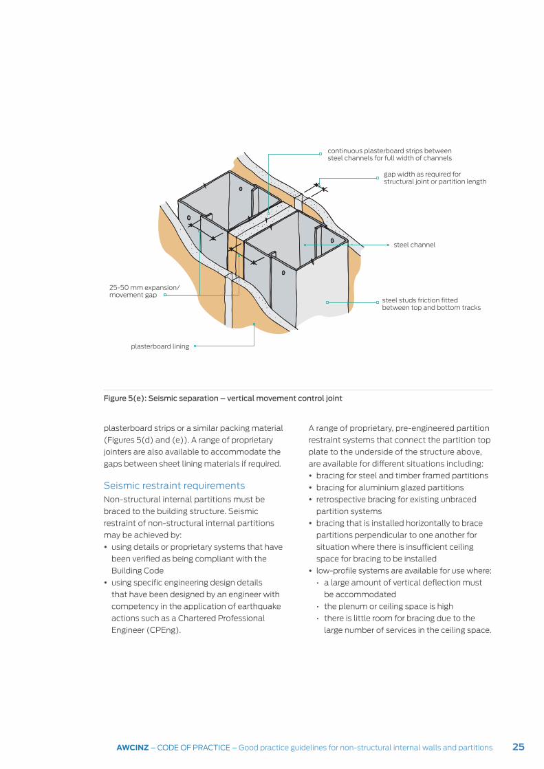
Figure 5(e): Seismic separation – vertical movement control joint
plasterboard strips or a similar packing material
(Figures 5(d) and (e)). A range of proprietary
jointers are also available to accommodate the
gaps between sheet lining materials if required.
Seismic restraint requirements
Non-structural internal partitions must be
braced to the building structure. Seismic
restraint of non-structural internal partitions
may be achieved by:
y using details or proprietary systems that have
been verified as being compliant with the
Building Code
y using specific engineering design details
that have been designed by an engineer with
competency in the application of earthquake
actions such as a Chartered Professional
Engineer (CPEng).
A range of proprietary, pre-engineered partition
restraint systems that connect the partition top
plate to the underside of the structure above,
are available for different situations including:
y bracing for steel and timber framed partitions
y bracing for aluminium glazed partitions
y retrospective bracing for existing unbraced
partition systems
y bracing that is installed horizontally to brace
partitions perpendicular to one another for
situation where there is insufficient ceiling
space for bracing to be installed
y low-profile systems are available for use where:
• a large amount of vertical deflection must
be accommodated
• the plenum or ceiling space is high
• there is little room for bracing due to the
large number of services in the ceiling space.
continuous plasterboard strips between steel channels for full width of channels
gap width as required for structural joint or partition length
steel channel
25-50 mm expansion/ movement gap
steel studs friction fitted between top and bottom tracks
plasterboard lining

26 AWCINZ – CODE OF PRACTICE – Good practice guidelines for non-structural internal walls and partitions
Seismic restraint systems are generally installed
at angles ranging between 30-600 in plan to the
partition being braced and perpendicular in plan
to partition returns or to straight partitions with
no return walls (Figure 6). They can generally
accommodate up to 50 mm of inter-storey drift,
90 mm of in-plane wall deflection and 20 mm
of out-of-plane wall deflection.
Installation of proprietary restraint
systems should be in accordance with the
manufacturer’s or supplier’s instructions which
may also require installation by specialist
installers.
Seismic requirements for glazed partitions
The same principles for providing seismic
separation and restraint of framed and lined
partitions must also be applied to glazed partitions.
Seismic separation can be achieved by providing
a minimum 50 mm deep channel in the head and
side glazing frames to accommodate seismic
movement without imposing force on the glass.
Seismic restraint for glazed partitions is the
same as for framed and lined partitions and
is required wherever glazed partitions do not
extend to the underside of the building structure.
Figure 6: Typical layout of seismic bracing for non-structural partitions
2.4 m
2.4 m2.4 m
3.0 – 4.8 m
1.5 m
≤ 3.0 m
1.5 m
≤ 3.0 m
90˚ 90˚90˚
90˚
30˚– 60˚30˚– 60˚
30˚– 60˚
30˚– 60˚

27AWCINZ – CODE OF PRACTICE – Good practice guidelines for non-structural internal walls and partitions
Some framing systems have removable glazing
beads that hold the glass in place in the frame.
A glazing bead allows the sufficient depth of
the pocket housing the glass to provide both
the edge cover and the movement allowance
required. However, some framing systems have
fixed pockets on two or more sides of a frame
(i.e. they do not have removable glazing beads).
This means that the frame rebate depth must be
minimal in order to be able to install the glass.
Following the New Zealand earthquakes, it was
observed that in some situations the glazed
partitions failed because the edge cover was
below the depth required to contain the glass.
Non-structural glazed partitions must be self-
supporting and there must be no loads applied
from above or the sides of the partition. Any
wall element above a glazed partition should
be isolated, either by being suspended from
above or with a lintel installed so that there is no
weight on the glazing or mullions.
Summary of design considerations for non-structural interior partitionsAs part of the interior partition design process,
a number of issues should be considered:
y the potential damage to non-structural
components that may occur as a result of the
deformation of structural components
y the need to accommodate seismic
separations in the building
y where partition systems are located in the
building as inter-storey drift increases higher
up the building
y whether building services systems must pass
through a non-structural partition, which
means the potential for impact damage during
seismic activity must be addressed
y whether fire, acoustic or thermal ratings must
be maintained
y the integrity of partitions separating exitways
that provide a safe means of exiting the
building in the event of an emergency, must be
maintained.
28 AWCINZ – CODE OF PRACTICE – Good practice guidelines for non-structural internal walls and partitions
Designing non-structural partitions using AS/
NZS 1170
As there are no acceptable solutions containing
specific reference or guidance for non-structural
partitioning systems, specific engineering design
(SED) with reference to AS/NZS 1170 is required.
Verification method B1/VM1 to Clause B1 of
the NZBC references the AS/NZS 1170 suite of
New Zealand Standards. Relevant parts of the
standard include:
y AS/NZS 1170.0: General Principles
y NZS 1170.5: Earthquake actions – New Zealand.
These Standards should be referred to when
designing the installation of non-structural
partitions.
AS/NZS 1170.0 requires buildings to be designed
and constructed so that during their design
working life, they are able to withstand all
actions and environmental influences that may
be imposed on them.
Section 3 of AS/NZS 1170.0 requires that
buildings must be able to withstand seismic
actions so that:
y the building does not collapse
y parts of the building do not collapse if they
present a hazard to people inside the building
y the non-structural systems that will enable
people to evacuate the building do not collapse.
y Determining level of seismic restraint required
y The first step in designing the non-structural
partitioning system is to obtain the building
information required to determine the level of
seismic restraint required. This includes:
5Design non-structural partitions using New Zealand Standard
y geographic location of the building
y building type – to establish building
importance level
y building importance level (IL)
y ultimate limit state (ULS)
y serviceability limit state (SLS)
y annual probability of exceedance
y consequences of building failure
y classification of building parts.
The methods to determine the building
information required are provided in AS/NZS
1170.0 and NZS 1170.5 and are summarised in
Table 1.
Geographic location and building type
Under NZS 3604:2011 Timber framed buildings,
New Zealand is divided into zones based on
environmental features including earthquake,
wind snow load and exposure.
NZBC Clause A1 classifies buildings according
to type in seven categories. A building with
a given classified use may have one or more
intended uses under the Building Act. The broad
classifications are:
y housing
y communal residential
y communal non-residential
y commercial
y industrial
y outbuildings
y ancillary.
Building Importance Level
Buildings have an importance level (IL) based
on the consequences of building failure after

29AWCINZ – CODE OF PRACTICE – Good practice guidelines for non-structural internal walls and partitions
a major event, and the risk to human life, the
economic cost and the ability for the building
to continue to function or be repaired. There
are five levels of importance, defined in NZBC
Clause A3 as follows:
y Level 1: Buildings and structures that present
a low degree of hazard to life or property, such
as outbuildings, fences and walls.
y Level 2: Buildings not included in the other
categories, such as timber-framed houses, car
parking buildings or office buildings.
y Level 3: Buildings that may have contents of
high value to the community or pose a risk to a
large number of people in close proximity, such
as conference centres, stadiums and airport
terminals.
y Level 4: Buildings that must remain functional
immediately after an earthquake or major event,
such as hospitals, communications centres and
other critical post-disaster buildings.
y Level 5: Structures whose failure poses a
catastrophic risk to a large area or a large
number of people, such as a dam or a
biological containment centre.
Standard Section/table Information
AS/NZS 1170.0 Section 3.3 and Table 3.2 Building importance level (IL)
Sections 3.2 and 3.4, Table 3.3 Annual probability of exceedance
Table 3.2 Building type
Table 3.1 Consequences of failure for importance levels
Section 2.2 Ultimate limit state (ULS) design procedure
Section 2.3 Serviceability limit state (ULS) design procedure
NZS 1170.5 Section 2.3 Ultimate limit state (ULS) verification
Section 2.4 Serviceability limit state (ULS) verification
Section 8 Requirements for parts and components
Table 8.1 Classification of building parts
Table 1: Determining building information from AS/NZS 1170.0 and NZS 1170.5
AS/NZS 1170.0, which is referenced from NZBC
Clause B1 Structure, also uses the building
importance levels to define ultimate limit state
(ULS) and serviceability limit state (SLS) for
the impact of wind, snow and earthquake levels
on buildings. AS/NZS 1170.0 also defines the
consequence of building failure in relation to
the building importance level. This is shown in
Table 2.
(Note: Although Clause A3 states that the
building importance levels refer only to NZBC
Clause C Protection from fire, they align with the
importance levels given in AS/NZS 1170.0)
When determining building importance levels,
if a building has multiple uses, the importance
level for the whole building shall be the highest
applicable level for any use in the building.
Limit state design
The structural design of buildings requires
consideration of all the loads that could
potentially act on a building over its lifetime,

30 AWCINZ – CODE OF PRACTICE – Good practice guidelines for non-structural internal walls and partitions
ranging from the ongoing in-service loads to rare
events such as a severe earthquake.
While the in-service design load is an
appropriate design level for ongoing loads on a
building, it does not deal with the loads that may
be imposed on rare occasions. This has resulted
in the development of the limit state design.
A limit state is the condition of a building
beyond which it no longer meets the specified
design criteria including the structural integrity,
functionality, durability or serviceability of the
building. and is the result of a level of loading or
some other action that is beyond the ability of
the building to withstand.
Two basic limit states are defined by AS/NZS
1170:
y the ultimate limit state (ULS), and
y the serviceability limit state (SLS).
Importance level
Type of building Examples Consequences of failure*
1 Building that present a low risk to life or other property
Structures with a total floor area less than 30 m2
Low
2 Normal buildings and those not in other importance levels
Single family dwellings Ordinary
3 Buildings that may have large numbers of people, pose a risk to crowds or contain items of high value to the community
Schools, healthcare facilities, correctional facilities, multi-occupancy residential, commercial, industrial, office and retail buildings, public assembly buildings, theatres and cinemas
High
4 Structures with special post-disaster functions
Buildings and facilities designated as essential, or with a special post-disaster function, medical emergency and surgical facilities
High
*Note: For definitions of consequences of failure, refer to the descriptions given in AS/NZS 1170.0, Table 3.1
Table 2: Description and examples of building importance levels (from AS/NZS 1170.0: 2002, Tables 3.1 and 3.2).
A structural engineer must provide both ULS and
SLS deflection criteria.
Ultimate limit state (ULS)
The ultimate limit state (ULS) requires that a
building remains standing after being subject to
its peak load such as may occur during a major
earthquake.
AS/NZS 1170 requires ULS design levels for
buildings based on their importance level and
design working life to be able to withstand
seismic events between 1-in-100 to 1-in-2500-
year probability. For example, the ULS design
level for an importance level 2 (IL2) building and
a 50-year design working life is based on a 1-in-
500-year earthquake.
Serviceability limit state (SLS)
The serviceability limit state (SLS) is the level of
load that a building of a particular importance
31AWCINZ – CODE OF PRACTICE – Good practice guidelines for non-structural internal walls and partitions
level can withstand after an earthquake and
still be used for its intended purpose without
repair. This means the level of load defined for
this limit state is low as it is a state expected to
be reached several times during the life of most
buildings in New Zealand.
There are two categories of serviceability limit
state (SLS): SLS1 and SLS2. These are defined
in AS/NZS 1170.0: 2002, 3.4.2 as follows:
y SLS1 – where structural and non-structural
components do not require repair after an
SLS1 earthquake, wind or snow event
y SLS2 – where the building must remain
functional after an SLS2 earthquake.
The higher serviceability limit state, SLS2, is
required for buildings with a high importance level
4 (IL4) such as hospitals, emergency services
buildings and so on, as it is required that they
will be fully operational within minutes or hours,
rather than days, following a seismic event.
A SLS1 design level applies to building with
importance levels 2-4 and must be able to
withstand an earthquake based on a 1-in-25-
year earthquake.
For more information, refer to the BRANZ
Seismic Resilience website at:
http://www.seismicresilience.org.nz/topics/
resilient-design/earthquake-engineering/limit-
state-design/
Serviceability limit state guidelines
Appendix C, Table C1 in AS/NZS 1170.0:
2002, provides guidelines and serviceability
parameters for the design of building elements
and components. For non-structural internal
partitions, these are shown in Table 3.
Annual probability of exceedanceThe annual probability of exceedance is
the probability of an event (such as an
earthquake) occurring in any year. It is based
on the building’s:
y design working life
y importance level
y ULS
y SLS (either SLS1 or SLS2).
AS/NZS 1170.0: 2002, Table 3.3 sets out the
annual probability of loadings (exceedance)
for earthquake, wind and snow for:
y ultimate limit state (ULS) for buildings
with designated importance levels 1-4,
and
y serviceability limit states 1 and 2 (SLS1
and SLS2) for buildings with designated
importance levels 2-4.
Classification of building parts and components
A building part9 is defined as:
y “a member that is either attached to and
supported by the structure but is no part of
the structural system, or
y an element of the structural system that can
be loaded by an earthquake in a direction that
it is not usually designed for”.
A building component10 is defined as “part of
a building too complex to be called a building
element, e.g. wall door, etc. which may be built
from several elements”.
An alternative definition of a part11 is “an
element that is not intended to participate
in the overall resistance of the structure to
horizontal displacement under earthquake
conditions for the direction being considered”.
9 From NZS 1170.5, p. 56
10 From NZMP 4212, p. 29
11 From NZS 1170.5, p. 59

32 AWCINZ – CODE OF PRACTICE – Good practice guidelines for non-structural internal walls and partitions
Table 3: Suggested serviceability limit state criteria (from AS/NZS 1170.0: 2002, Appendix C, Table C1)
Element Phenomenon controlled
Serviceability parameter
Element response(1)
Walls
General
face loaded discerned movement
mid height deflection
height/150
impact: soft body mid height deflection
height/200 but < 12 mm(2) (3)
supported elements rattle
mid height deflection
height/1000
Walls(4)
Plaster/gypsum
in plane lining damage mid height deflection
Height/300
face loading lining damage mid height deflection
Height/200
Glazing Glazing system bowing mid span deflection Span/400
Fixed glazing system
glass damage mid span deflection 2 x glass clearance(5)
Notes:
1 The span or height ratios used in the deflection criteria are the clear spacing between parts of support.
2 Walls and partitions require stiffness control to minimise disturbance such as neighbours on the other side of an inter-tenancy wall. The stated deflection criteria (height/200 from a concentrated load of 0.7 kN at mid-height) has been simplified for ease of application and is based the impact of a person running and falling against a wall.
3 Internal partitions may also be subjected to differential pressures as a result of wind pressure. A net coefficient of 0.5 may be considered appropriate when used in conjunction with the serviceability wind pressures.
4 Different wall linings have different movement tolerances so some are identified.
5 The surface finish and size of partitions may affect the observed deflections of ceilings and floors, e.g. the reflective surface of glass amplifies apparent bowing by the reflected images as they move with the surface distortions. Ripple effects are more apparent on flat surfaces, while textured surfaces tend to disguise ripple effects. Large surface areas appear to move more than smaller surface areas. Where the texture of the surface is unknown, design should be to a higher deflection limit.
According to these definitions, partitions and
non-load bearing walls can be defined as both
building parts and components.
NZS 1170.5: 2004 is the design actions
standard cited by verification method B1/
VM1 to NZBC clause B1 Structure. Section
8 of NZS 1170.5 addresses the seismic
performance requirements for building parts
and components and classifies them into one
or more categories, P1-P7, based on specific
performance criteria.
Under each category there is also an associated
ULS or SLS requirement. These are summarised
in Table 4. Note that the category requirements
apply to the parts and components following an
earthquake but do not apply to fire safety and
safe egress if there is a fire.
A system is assigned a part category according
to its potential to cause death or injury, or its
importance for the continued functioning of
the building, or if the consequential damage is
high. For example, categories P2 and P3 apply

33AWCINZ – CODE OF PRACTICE – Good practice guidelines for non-structural internal walls and partitions
where a system represents a hazard to human
life inside a building, while category P4 requires
parts and components to continue to function to
enable the building to be safely evacuated, and
for life safety systems in the building to continue
to function. The ULS applies for the design of
categories P2-P4.
A part is considered a hazard to human life if
it weighs more than 7.5 kg and is able to fall
more than 3 m. A partition system that comes
within these criteria needs to be designed to the
ultimate limit state.
Structural design procedures in accordance with Standards
Section 2 of AS/NZS 1170.0 sets out structural
design procedures for the ULS (Clause 2.2) and
SLS (Clause 2.3).
AS/NZS 1170.0, clause 2.2 sets out the design
procedure for the ULS as follows:
y Determine the building importance level (IL)
and the associated annual probability of
Category Criteria Structure limit state
P1 Building component presents a hazard to people outside the building ULS
P2/P3 Building component presents a hazard to people inside the building (includes heavy partition systems)
ULS
P4 Building component necessary for the continuing function of the evacuation and life safety support systems in the building
ULS
P5 Building component required for:
y IL4 building; building required to have operational continuity:
y functionality for building to be redeveloped
SLS2
P6 Where the consequential damage caused by a component failure is disproportionately great
SLS1
P7 All other components SLS1
Table 4: Classification of building parts and components (from NZS 1170.5:2004 Table 8.1).
exceedance for wind, snow and earthquakes
from AS/NZS 1170.0, section 3.
y If required, determine the ultimate load for
wind from AS/NZS 1170.2.
y Determine the ultimate load for earthquakes
from NZS 1170.5.
y Design and detail the structure in accordance
with NZS 1170.5 for earthquakes.
AS/NZS 1170.0, clause 2.3 sets out the design
for the SLS as follows:
y Determine the type of design serviceability
condition to be considered.
y Determine the design situation including
serviceability load and serviceability limits for
the condition being considered from AS/NZS
1170.0, section 3.
y If required, determine the serviceability load
for wind from AS/NZS 1170.2.
y Determine the serviceability limits applicable
to earthquake loading from NZS 1170.5.
AS/NZS 1170.0, clause 3.2 sets out design
requirements include that buildings must

34 AWCINZ – CODE OF PRACTICE – Good practice guidelines for non-structural internal walls and partitions
be able to withstand all actions during their
lifetime as follows:
y for earthquakes:
• to avoid collapse of building parts that
present a hazard to life, and
• to avoid damage to non-structural elements
that are necessary for evacuation of the
building
y to perform adequately under all expected
actions (serviceability requirement).
The information for the design of non- structural
partitions should be supplied to the interior
partition systems supplier by a structural
engineer.
Wind loads on buildings
Wind loads on the building exterior cause
pressure changes to the exterior that can result
in a pressure differential across the exterior wall,
affecting the internal pressure. Internal pressures
can be sufficiently significant to need to be
considered for interior partition design.
Wind actions on buildings are determined and
calculated in accordance with AS/NZS 1170.2: 2011:
y for site wind speeds – paragraph 2.2
y for design wind speeds – paragraph 2.3
y for design wind pressures and distributed
forces – paragraph 2.4
y to calculate wind actions – paragraph 2.5.
Designing glazed partitions using NZS 4223.3
Requirements for glazed partitions are set out
in NZS 4223.3: 2016 Glazing in buildings. Part 2 –
Human impact safety requirements.
The NZBC Clause A1 identifies a range of
building usages that must be glazed in
accordance with NZS 4223.3, sections 3.2, 3.3
and 3.4. These include assembly care buildings
such as schools and early childhood centres,
communal residential buildings, commercial and
industrial buildings, and other buildings where
there is a high risk of injury from glazing.
The New Zealand Standard, NZS 4223.3
describes glazing requirements for all glazing
that is wholly or partly within 2000 mm from
a floor or ground level. Other requirements for
glazing include for fully framed, partly framed
and unframed partitions.
35AWCINZ – CODE OF PRACTICE – Good practice guidelines for non-structural internal walls and partitions
An integrated approach to design
The design and installation of non-structural
interior partition systems requires collaboration
and integration between all the relevant
disciplines involved in the building project. This
generally includes:
y the designer or architect
y a structural engineer and/or specialist
seismic engineer
y services engineers (MEP and HVAC).
A collaborative approach involves disciplines
working together to jointly analyse problems,
provide feedback on design options and
solutions, and collectively make decisions
at each stage of the project. It also includes
having regular meetings and maintaining good
communication between all relevant parties
of a building project and should begin as early
as practicable. It is also important to identify
and agree on oversight and management
methodologies for key coordination issues.
Factors to facilitate the development of the
building project include:
y involving all relevant parties as early as
possible in the project so that:
• problems are identified and resolved early
in the project rather than becoming major
issues during the construction phase
• critical decisions made in the early stages
of the project
• specialist areas can be designed with the
requisite seismic restraints
y obtaining all the required information from
relevant disciplines at the start of the
project
6An integrated approach to design
y ensuring appropriate oversight by employing
a specialist non-structural seismic co-
ordinator who will be responsible for
overseeing all of the interior non-structural
partitioning and ensuring that the specified
systems and products are installed.
Critical decisions made in the early stages of
a project are easier to make, less costly and
more effective than when they are made later in
the project. Early engagement and interaction
between all parties involved can ensure that:
y design objectives are clarified and refined early
in the project
y appropriate performance levels are set, and
y the best design solutions are identified early in
the design process.
The need for collaboration and coordination
Investigation by the Ministry of Business,
Innovation and Employment (MBIE) into
building project practices has found that a lack
of collaboration is likely to result in:
y misunderstandings and incorrect assumptions
y groups not being aware of changes to the
design being made elsewhere.
y delays in progress
y inefficiencies
y the need to repeat work.
An advisory published by MBIE, Practice Advisory
19 Improving earthquake performance of non-
structural elements, provides advice to building
practitioners on the need for a well-planned
and coordinated approach to the design and
construction of seismically restrained non-

36 AWCINZ – CODE OF PRACTICE – Good practice guidelines for non-structural internal walls and partitions
structural elements in a building. Although the
practice advisory refers primarily to building
services such as mechanical and electrical plant,
ducting, pipework, cable trays and suspended
ceilings, the advice can also be applied to
lightweight, non-loadbearing partitions.
To see the advisory, refer to MBIE website:
https://www.building.govt.nz/building-
code-compliance/b-stability/b1-structure/
practice-advisory-19/improving-earthquake-
performance-non-structural-elements/
The Canterbury Earthquakes Royal
Commission recommended that a structural
Chartered Professional Engineer (CPEng)
should be engaged at the same time as the
architect for the design of a complex building.
A guidance document, Improving Collaboration
between Architects and Engineers that was put
together by a number of different agencies,
strongly recommends collaboration between
disciplines. It is available online at:
https://www.nzrab.nz/Editable/Assets/
Newslink2015/CollaborationPublication.pdf.
Non-structural seismic coordinator
A specialist non-structural seismic
coordinator should be included in the design
team for larger projects. A suitably qualified
coordinator would:
y prepare seismic restraint layout drawings
y design details for the installation of non-
structural partitions including all junctions of
partitions and walls with building structure
y be responsible for ensuring that non-structural
partition systems are designed and installed
as specified
y monitor the installation and construction of
the seismic restraint system.
Structural information including the seismic
design criteria such as SLS and ULS for
the proposed building, and specific design
information required for the internal partitioning
should be provided by the structural engineer.
Partition manufacturers also often provide
design information such as seismic restraint
tables and guidelines.
Establishing design parameters
The design parameters for the non-structural
elements should be determined at the
preliminary design phase of a building project.
The location of the bracing or seismic restraint
for ceiling-height and full-height partitions
must be coordinated with other non-structural
building components that need to be located in
the ceiling space such as sprinkler systems, air-
conditioning ducts, cabling ducts, and lighting
systems. Ceiling spaces often have very limited
space so the design and layout of the ceiling
space must be carefully planned to ensure there
are no component clashes.
When designing the layout for the seismic
restraint of partitions in the ceiling space,
considerations should include the:
y characteristics of the building structure
y location of non-structural partitions in the
building
y type of anchorage or restraint system
y potential interaction between structural and
non-structural elements.
The layout of the ceiling space and the location
of all components including seismic restraints
in the ceiling space, should be completed
and included as part of the building consent
documentation the tender process.

37AWCINZ – CODE OF PRACTICE – Good practice guidelines for non-structural internal walls and partitions
Construction Industry Council (CIC) Guidelines
The New Zealand Construction Industry
Council’s (NZCIC) 2016 Design Documentation
Guidelines provides a good template on which
to base an integrated design approach. They
set out guidelines for all disciples involved in a
building project including:
y roles and responsibilities
y the coordination and design interfaces
between parties
y a checklist to define the design processes
y a schedule of activities to be carried out.
The guidelines provide useful general checklists
and benchmarks for the design, construction
and monitoring of the building project.
CIC Guidelines (2016) stages
Design principle
Requirements Parties required to input, assist and coordinate
Deliverables required and parties responsible
Concept design General Seismic design Architect, Project manager
Structural engineer
Preliminary design
General Seismic design Architect Structural, MEP, Fire engineers
Developed design
General Seismic design Architect Structural, MEP, Fire engineers
Detailed design General Structural/geotech
Proprietary design
Architect Structural, MEP, Fire engineers
Procurement Structural/geotech
Erection/construction
Architect, Project manager, Structural, MEP, Fire engineers
Construction, Administration, Observation
General Seismic design Architect, Project manager, Structural, MEP, Fire engineers
Contractor
Table 5 shows which parties are involved at
particular stages of the building project and who
should provide the deliverables.
Roles and responsibilities
The process outlining who may be involved
and what their roles are is shown in Figure 7.
Note that not all steps will be relevant for all
construction projects.
Specific roles
The architect or designer is generally
responsible for the overall design of the building
and oversees the coordination of the design
input from the specialist disciplines such as
structural, building services (MEP), and fire
engineers.
Table 5: Parties involved in stages of a building projected (adapted from CIC Guidelines (2016)).

38 AWCINZ – CODE OF PRACTICE – Good practice guidelines for non-structural internal walls and partitions
Figure 7: Process for the design of a non-structural interior partition system
Who is involved Procedure
* Designer refers to architect, architectural designer, specialist interior designer.
Selection options
Use manufacturer’s installation details
Design by a suitably qualified person (engineer/ seismic specialist)
SLS
SLS1 SLS2
ULS
Service to pass below ceiling
Service to pass in the ceiling space
IL1 IL2 IL3 IL4 IL5
P1 P2 P3 P4 P5 P6 P7
Designer Select partition system
Determine the ultimate and service limit states for all elements
Engineer/seismic specialist
Apply for building consent including partition design documentation in application
Designer
Engineer/seismic specialist (coordinate with services specialists)
Determine which services must pass through partitions
Design appropriate seismic restraints
Determine building importance level (IL)
Determine building category
Designer*/engineer/seismic specialist or coordinator

39AWCINZ – CODE OF PRACTICE – Good practice guidelines for non-structural internal walls and partitions
The structural engineer is responsible for:
y the structural design of the building
y providing the seismic design criteria for the
non-structural elements in the building.
Building services engineers (MEP) are
responsible for designing and installing
specialist building services such as heating
and ventilation systems, electrical, data and
communication systems, and plumbing and
drainage systems.
Fire engineers are responsible for the fire safety
design of buildings including materials and
construction, means of egress, preventing the
spread of fire and firefighting facilities.
The main contractor is responsible for:
y providing the materials, labour, equipment and
services required for the construction of a building
y overseeing the construction process
y managing the coordination of seismic
solutions and details by relevant trade
contractors including services, ceiling and
partition subcontractors
y communicating any changes that may affect
the seismic design of any of the restraint
systems to the architect, designer or specialist
non-structural partition coordinator.
Subcontractors and tradespeople are
responsible for the installation of building services,
fixtures and fittings within the scope of their trade.
Construction monitoring
Construction monitoring involves site visits
and reviewing the contract design information
to ensure that materials and methods of
installation are in accordance with the contract
documents, specification and performance
criteria requirements. Traditionally the primary
and secondary structural elements of a building,
which are engineer-designed and detailed, are
closely monitored while non-structural elements
tend to be overlooked or poorly monitored and
managed during the design, procurement and
construction phases of the project.
On-site monitoring is crucial in the construction
process to ensure that details of construction
such as fixings and anchorages, seismic
clearances and movement allowances are
constructed or provided as detailed.
Monitoring of internal partition installation
should be carried out by the architect or
designer, a structural engineer, interior
partitioning system designer or, if employed, the
non-structural seismic coordinator.
Producer statements
A producer statement is a professional opinion
that may be used to contribute to the evidence
that proposed work will meet compliance with
the Building Code. If a producer statement
is used it should be submitted with the
construction documentation.
Producer statements are typically used for
specialist work or proprietary products that are
to be installed by specialist contractors. There
are four types of producer statement referring
to different statements relating to:
y PS1 – Design
y PS2 – Design review
y PS3 – Construction
y PS4 – Construction review.
A PS3 is sometimes used by the installers of
proprietary systems such as partitioning systems.
40 AWCINZ – CODE OF PRACTICE – Good practice guidelines for non-structural internal walls and partitions
ProcurementProcurement deals with acquiring (procuring)
the goods, services and activities that are
essential to the building project. It constitutes
the overarching process under which
purchasing is one part. Procurement involves a
number of processes including:
y recruiting the right contract workers
y sourcing products
y establishing payment terms
y negotiating contracts
y purchasing goods
y logistically managing the transportation of
materials between facilities and sites.
Procurement is essential to the success of a
construction project as it encompasses the
logistical management of goods and services
at all levels of the construction project, and is
dependent on expertise, industry knowledge
and reliable strategies to meet the required
objectives of the project.
Issues from design-build projects
Large projects are sometimes fast-tracked
by dividing the construction contract into
a number of separate tenders that may be
negotiated with a single supplier or as a
competitive tender. Although the aim of a
design-build project is to shorten the time for
a construction project, it can also substantially
complicate coordination. There are a number of
reasons for this including that:
y the full design team has often not been
decided on before the preparation of
construction documentation has begun.
This can cause problems when decisions
about the design must be made early in the
project but the parties who will be responsible
for particular aspects of the design and
construction have not yet been contracted and
therefore have no input into design decisions.
y communication among disciplines in fast-
track projects is generally more difficult due to
the development of separate tender packages
resulting in a fragmented design process.
y the demands of a rushed project schedule
may mean that aspects of design and
fabrication such as shop-drawing preparation,
are not always being thoroughly checked by
the architect or engineer.
y the complexity of some projects can hinder
effective cooperation and coordination
between design teams that have not
previously worked together. This highlights
the importance of adequately defining
performance objectives and assigning roles
and responsibilities if integrated seismic
design and construction is to be achieved.
41AWCINZ – CODE OF PRACTICE – Good practice guidelines for non-structural internal walls and partitions
Services such as ducting, sprinkler pipes, cables,
water pipes and fire and smoke dampers in
commercial buildings are often able to be
installed in the suspended ceiling space, but in
some situations, services must pass through
partitions. This may occur where there is no
ceiling space, or where services must pass from
one occupancy to another or from one firecell
to another in the same occupancy. Partitions
separating different occupancies or firecells
within an occupancy must be fire-rated and the
fire rating must be maintained for the specified
time of the rating at all times.
During an earthquake, suspended services
pipes and ducting move and sway but not in
synchronisation with the building structure or
the partitions. If there is insufficient clearance
around a penetration through the partition, the
services pipes are likely to knock against the
partition, potentially causing damage to both.
The consequences of damage to penetrations,
particularly fire-rated penetrations, are severe:
y in the event of a fire, the fire resistance
rating (FRR) of the partition is likely to be
compromised potentially causing the premature
spread of fire from one firecell to another and
putting the lives of building occupants at risk
y damage to pipework such as sprinkler and
water pipes can cause the pipes to fracture or
pull apart and flood the building
y fractured or broken pipes also mean there will
be no water available for firefighting.
Some partitions are designed with a thermal or
acoustic rating. While the loss of these ratings
7Penetrations through partitions
is not likely to endanger the lives of building
occupants, damage following a low to moderate
earthquake can be costly both in terms of repairs
and loss of building functionality.
Generally, a situation-specific solution should
be designed for each penetration through a
non-structural partition but there are some
guidelines that should be followed.
Guidelines for penetrations through partitions
Where possible, the building design should
avoid requiring the need for services
penetrations to go through fire-rated partitions
by designing a different route for the service.
Where penetrations are unavoidable, there
are a number of alternatives to help minimise
potential damage such as:
y planning coordinating services during the
design phase to avoid penetrations where
possible
y combining services to go through the same
penetration to minimise the number of
penetrations required
y providing adequate clearances around
penetrations
y avoiding fixing services components to the
partition penetration
y avoiding fixing services components to and
part of a lightweight partition.
Clearances around penetrations
NZS 4219:2009 Seismic performance of
engineering systems in buildings requires a
50 mm clearance around services through
penetrations in a structural element such as a

42 AWCINZ – CODE OF PRACTICE – Good practice guidelines for non-structural internal walls and partitions
wall or a floor. The clearance is intended to avoid
impact or interaction due to differential seismic
movement between the service component
and the structure. The same principle should be
applied where service penetrations pass through
non-structural partition systems.
To create a clearance around a penetration
through a lightweight framed partition, a frame
to provide clearance should be constructed
around the penetration (Figure 8). A suitable
stopping material is then inserted around the
framing.
Figure 8: Clearance and fire stopping around a penetration
Fire stopping materialsA range of fire stopping materials is available
to provide fire protection for fire stopping and
sealing penetrations in fire rated elements
including non-structural partitions. Generic
products include:
y mineral fibre mats/strips
y foam
y bags/pillows
y plugs/blocks
y pipe closures
y sealants/mastics
y preformed elastomeric seals.
plasterboard lining50 mm minimum clearance
steel stud framing
clearance around penetration filled with suitable fire-rated stopping material
pipe collar
framing around service penetration opening
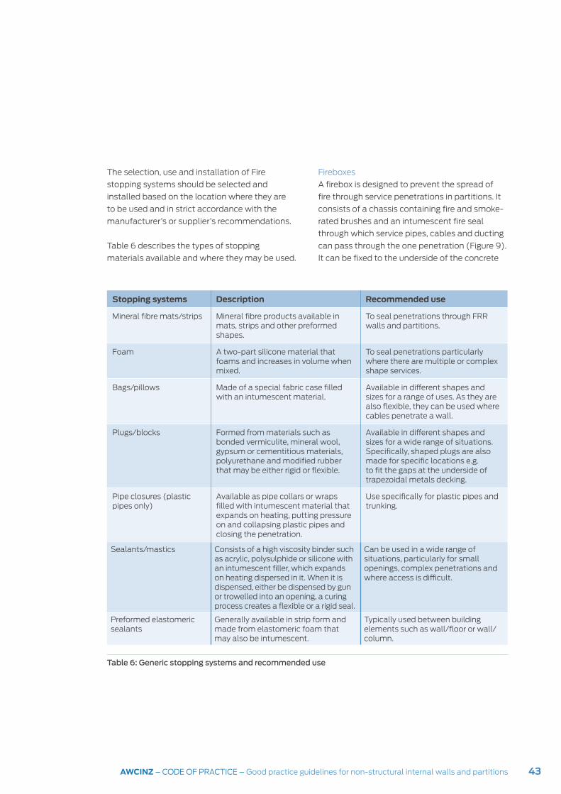
43AWCINZ – CODE OF PRACTICE – Good practice guidelines for non-structural internal walls and partitions
Stopping systems Description Recommended use
Mineral fibre mats/strips Mineral fibre products available in mats, strips and other preformed shapes.
To seal penetrations through FRR walls and partitions.
Foam A two-part silicone material that foams and increases in volume when mixed.
To seal penetrations particularly where there are multiple or complex shape services.
Bags/pillows Made of a special fabric case filled with an intumescent material.
Available in different shapes and sizes for a range of uses. As they are also flexible, they can be used where cables penetrate a wall.
Plugs/blocks Formed from materials such as bonded vermiculite, mineral wool, gypsum or cementitious materials, polyurethane and modified rubber that may be either rigid or flexible.
Available in different shapes and sizes for a wide range of situations. Specifically, shaped plugs are also made for specific locations e.g. to fit the gaps at the underside of trapezoidal metals decking.
Pipe closures (plastic pipes only)
Available as pipe collars or wraps filled with intumescent material that expands on heating, putting pressure on and collapsing plastic pipes and closing the penetration.
Use specifically for plastic pipes and trunking.
Sealants/mastics Consists of a high viscosity binder such as acrylic, polysulphide or silicone with an intumescent filler, which expands on heating dispersed in it. When it is dispensed, either be dispensed by gun or trowelled into an opening, a curing process creates a flexible or a rigid seal.
Can be used in a wide range of situations, particularly for small openings, complex penetrations and where access is difficult.
Preformed elastomeric sealants
Generally available in strip form and made from elastomeric foam that may also be intumescent.
Typically used between building elements such as wall/floor or wall/column.
The selection, use and installation of Fire
stopping systems should be selected and
installed based on the location where they are
to be used and in strict accordance with the
manufacturer’s or supplier’s recommendations.
Table 6 describes the types of stopping
materials available and where they may be used.
Table 6: Generic stopping systems and recommended use
Fireboxes
A firebox is designed to prevent the spread of
fire through service penetrations in partitions. It
consists of a chassis containing fire and smoke-
rated brushes and an intumescent fire seal
through which service pipes, cables and ducting
can pass through the one penetration (Figure 9).
It can be fixed to the underside of the concrete

44 AWCINZ – CODE OF PRACTICE – Good practice guidelines for non-structural internal walls and partitions
slab of the floor above so it is independent of
the partition framing, installed in new partition
construction or retrofitted into an existing
partition system. Fireboxes are available in a
range of sizes that will suit most situations.
When installing a firebox, ensure there is
sufficient space on both sides of the unit where
it goes through a partition to install cable or pipe
hangers as the penetrating services must be
supported independently of the firebox.
Fire and smoke dampers
Fire and smoke dampers are installed with
ducting systems where the ducting passes
through fire rated walls. under normal conditions
Figure 9: Typical firebox installation through FRR partition
the damper allows air to flow through the duct
but if a fire breaks out, the intumescent material
within the damper will expand to form a non-
combustible, insulating fire stopping barrier.
Fire and smoke dampers must also be fixed
independently of partition penetrations. They
should:
y be installed using flanges fixed to the fire
damper sleeve but not to the wall to allow for
thermal expansion during a fire
y have a separation between the fire damper
sleeve and the penetration in accordance with
the manufacturer’s recommendations
y have the gap created by the separation packed
with a compressible, non-combustible material.
foam packing fitted snugly around penetrating services
timber framing
cables/pipes
firebox chassis
flange surround to firebox
plasterboard lining
20 mm minimum intumescent sealant over backing rod on all sides of firebox
45AWCINZ – CODE OF PRACTICE – Good practice guidelines for non-structural internal walls and partitions
This section contains generic details showing
typical methods of construction for seismic
restraint and separation of non-structural
internal partitions. Note that when proprietary
products are used, manufacturer’s instructions
should be followed.
Generic details and solutions
New solutions and design details are required
to mitigate the damage that occurs to non-
structural partition systems during seismic
events. Architects and designers must move
away from designing internal partitions with a
monolithic finish by designing to:
y allow independent movement of non-
structural partitions by isolating them from the
building structure
y provide lateral stability by bracing partial
height partitions to the building structure.
Although there is a preference for a clean
finish where joints, junctions and intersections
between different materials flowing smoothly
and seamlessly from one to the other, this
method of construction and finishing has proved
to be unsuccessful under seismic conditions.
Alternative finishes could include:
y incorporating shadow lines or negative details
at wall junctions and intersections
y breaking up large areas of wall with regularly
spaced control joints
8 Generic details
y covering gaps with trim finishes that allow
movement.
Partition construction
To construct framed and lined partitions with
seismic separations:
1. Fix steel channel top and bottom tracks to
the floor and the underside of the building
structure above (concrete floor, beam, roof)
over plasterboard* or similar strips that are
full depth of the tracks.
2. Fix steel channel perimeter tracks to the
building structure (column, exterior wall or
structural wall) over plasterboard* or similar
strips that are full depth of the tracks.
* Note that where partitions are required
to be fire-rated, the packing material must
be plasterboard or a proprietary fire barrier
material.
3. Friction fit studs, either steel or timber,
between the top and bottom tracks leaving a
10-15 mm deflection gap between the top of
the stud and the top track.
4. Allow a 25-50 mm gap between the edge
track and the adjacent stud.
5. Fix lining material at all edges and across the
sheets to the studs only. Do not fix the lining
to the top, bottom and perimeter tracks.
Refer to Figures 10 to 25.

46 AWCINZ – CODE OF PRACTICE – Good practice guidelines for non-structural internal walls and partitions
Figure 10(a): Full height FRR partition head detail – steel channel/timber studs
Figure 10(b): Full height FRR partition base detail – steel channel/timber studs
continuous plasterboard strips between track and underside of building structure for full width of track
steel channel top track
10-20 mm gap – top track to underside slab/structure
10-15 mm expansion gap – stud to top track
timber stud friction fitted between top and bottom tracks
underside of slab/structure above
10-15 mm gap between lining and structure
plasterboard lining
fix lining to studs only (i.e. do not fix lining to track)
timber stud friction fitted between top and bottom tracks
steel channel top track
proprietary skirting fixed to studs only
fix lining to studs only (i.e. do not fix lining to track)
plasterboard liningfloor slab
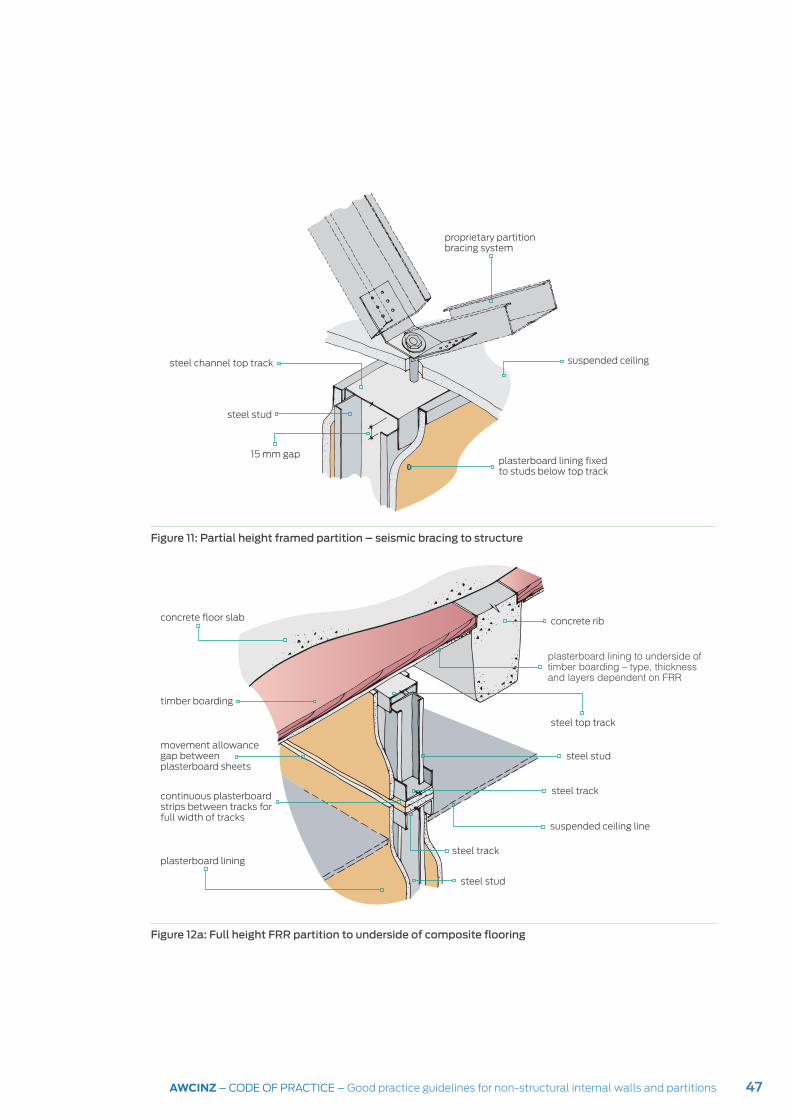
47AWCINZ – CODE OF PRACTICE – Good practice guidelines for non-structural internal walls and partitions
Figure 11: Partial height framed partition – seismic bracing to structure
Figure 12a: Full height FRR partition to underside of composite flooring
proprietary partition bracing system
steel channel top track suspended ceiling
steel stud
plasterboard lining fixed to studs below top track
15 mm gap
concrete floor slab
timber boarding
steel top track
plasterboard lining to underside of timber boarding – type, thickness and layers dependent on FRR
concrete rib
steel stud
steel track
movement allowance gap between plasterboard sheets
suspended ceiling line
continuous plasterboard strips between tracks for full width of tracks
steel track
steel stud
plasterboard lining
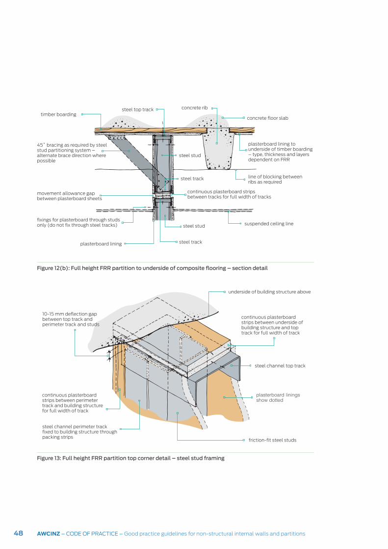
48 AWCINZ – CODE OF PRACTICE – Good practice guidelines for non-structural internal walls and partitions
Figure 13: Full height FRR partition top corner detail – steel stud framing
Figure 12(b): Full height FRR partition to underside of composite flooring – section detail
45˚ bracing as required by steel stud partitioning system – alternate brace direction where possible
steel top track
steel stud
timber boarding
plasterboard lining to underside of timber boarding – type, thickness and layers dependent on FRR
movement allowance gap between plasterboard sheets
fixings for plasterboard through studs only (do not fix through steel tracks)
steel track
continuous plasterboard strips between tracks for full width of tracks
steel track
line of blocking between ribs as required
concrete rib
plasterboard lining
steel stud
suspended ceiling line
concrete floor slab
underside of building structure above
continuous plasterboard strips between underside of building structure and top track for full width of track
10-15 mm deflection gap between top track and perimeter track and studs
continuous plasterboard strips between perimeter track and building structure for full width of track
steel channel perimeter track fixed to building structure through packing strips
steel channel top track
plasterboard linings show dotted
friction-fit steel studs

49AWCINZ – CODE OF PRACTICE – Good practice guidelines for non-structural internal walls and partitions
Figure 15: Alternative partition head details – (a) Double top track detail
Figure 14: Full height FRR partition bottom corner detail – steel stud framing
line of column or structural wallcontinuous plasterboard strips between perimeter track and building structure for full width of track
expansion/seismic gap between perimeter track and building structure as required for calculated drift
friction-fit steel studs
plasterboard linings shown dotted
steel channel perimeter track fixed to building structure through packing strips
steel channel bottom track
fix lining to studs only (i.e. do not fix lining to tracks)
floor slab
underside of slab/structure above continuous plasterboard strips between track and underside of building structure for full width of track
steel channel top track fixed through plasterboard strips to underside of building structure
secondary track
10-15 mm gap between lining and structure
10-20 mm gap – top track to underside slab/structure
10-15 mm defection gap – top track to second track
steel studs fixed to secondary track and friction fitted to bottom track
fix lining to secondary track and studs only
plasterboard lining

50 AWCINZ – CODE OF PRACTICE – Good practice guidelines for non-structural internal walls and partitions
Figure 16: Corner detail – steel stud framing
Figure 15: Alternative partition head details – (b) Steel channel track with slotted holes for vertical and in plane movement accommodation
steel channel top and perimeter track
longitudinal slotted holes to accommodate in plane movement – install fastening through centre of slot
vertical slotted holes to accommodate vertical movement – fix studs and plasterboard to track through slotted holes
steel track
gap as required for calculated building drift
plasterboard lining
steel track
plasterboard lining
steel studs friction fitted between top and bottom tracks
steel studs friction fitted between top and bottom tracks
gap as required for calculated building drift
plasterboard lining

51AWCINZ – CODE OF PRACTICE – Good practice guidelines for non-structural internal walls and partitions
Figure 17: Full height partition head detail – proprietary deflection track
Figure 18: Partition edge detail – proprietary deflection track
underside of building structure
proprietary deflection track
25 mm deflection gap
proprietary deflection channel
plasterboard capping
plasterboard lining
15 mm gap
friction-fit steel stud
line of building structure proprietary deflection track
proprietary deflection channel
proprietary plasterboard capping
plasterboard lining
deflection gap as required for calculated drift
proprietary skirting fixed to studs only

52 AWCINZ – CODE OF PRACTICE – Good practice guidelines for non-structural internal walls and partitions
Figure 20: Glazed partition head detail – 50 mm aluminium glazing track
Figure 19: Glazed partition head detail – proprietary deflection track/standard aluminium glazing track
underside of building structure
25 mm deflection gap
proprietary deflection track
proprietary deflection channel
aluminium glazing track
glass
underside of building structure
50 mm aluminium glazing track
15 mm seismic gap
glass

53AWCINZ – CODE OF PRACTICE – Good practice guidelines for non-structural internal walls and partitions
Figure 22: Glazed partition jamb/sill detail – 50 mm aluminium glazing track
Figure 21: Glazed partition jamb/sill detail – proprietary deflection track/standard aluminium glazing track
building structure25 mm deflection gap
proprietary deflection track
proprietary deflection channel
aluminium glazing jamb
gasket
glass
aluminium glazing sill
glazing block
25 mm typical depth
building structure
aluminium glazing jamb
15 mm seismic gap
gasket
glass
aluminium glazing sill
50 mm typical depth

54 AWCINZ – CODE OF PRACTICE – Good practice guidelines for non-structural internal walls and partitions
Figure 24: Steel frame/plasterboard lined partition/glazed partition junction
Figure 23: Glazed partition head detail – seismic bracing to structure/50 mm aluminium glazing track
proprietary partition bracing system
glass
plasterboard lining
plasterboard capping
25 mm deflection gap
glazing gaskets
glass
glazing gaskets aluminium glazing frame
glass
proprietary deflection channel
proprietary deflection track
suspended ceiling
aluminium glazing head
55AWCINZ – CODE OF PRACTICE – Good practice guidelines for non-structural internal walls and partitions
Improving the seismic performance of non-structural partitions A paper presented to the 2014 New Zealand
Society for Earthquake Engineering conference12
proposed the following actions for improving
the seismic performance of non-structural
partitions:
y Include the structural design criteria
directly on the drawings – this information
should be provided by the structural engineer
and include both seismic load and drift
expectations. It will provide contractors,
manufacturers and the designers of
non-structural partitions with the design
requirements for the partitions.
y Identify and provide a list of the design and
inspection requirements for non-structural
components as part of the building consent
documentation.
y Require a PS1 (design) to be submitted by
the appropriate design engineer, contractor
or an engineer employed by the contractor for
the identified non-structural elements [to]
provide clarity of design responsibility for these
elements with regulatory overview provided
by building officials. It should be linked to the
list of design and inspection requirements
provided as part of the building consent
documentation.
y Require a PS4 (construction review) for
specified non-structural elements. [This] will
address concerns surrounding construction
review and verification of most non-structural
elements.
y Review the New Zealand Building Code and
standards relating to non-structural bracing
y Encourage bracing for non-structural
elements and systems to be listed separately
from the equipment in tenders.
y Encourage education of all involved
in the construction industry (including
designers, contactors and building owners)
about damage limitation and prevention, the
benefits of damage limitation, and how this
can be achieved. Education across the industry
is vital to improve the performance of non-
structural elements in earthquakes.
12 From Seismic performance of non-structural elements within building presented by H. Ferner, M. Wemyss, A. Baird & A. Beer (Beca Ltd, Auckland, New Zealand) D. Hunter (Fletcher Construction, Auckland New Zealand), p.7

56 AWCINZ – CODE OF PRACTICE – Good practice guidelines for non-structural internal walls and partitions
9Building Information Modelling (BIM)
Overview of BIM
Over the past 30 years, CAD software has
evolved from 2D drawings into 3D integrated
building information modelling (BIM)
applications that coordinate and integrate all the
information about the building. The BIM model
contains information and data about the design,
construction and maintenance of the building
throughout its life from initial conception and
design to demolition.
The concept of BIM is a virtual building model
that functions in the same way as the actual
building model will once it has been built. This
is achieved by embedding the data about
the building into a 3D model to integrate and
coordinate the building information supplied by
all different groups involved in the construction
project. It can update the data automatically
when changes are made to the model and as a
3D model, it can provide easy visualisation of the
project.
The BIM model can be made accessible to
everyone involved in the project so when
changes are made, they will be available to
everyone, potentially eliminating many of the
problems that arise from issues such as clashes
between building elements.
Once the model has been built, it can be
developed, analysed, tested, tweaked, and
altered in its virtual format, before the actual
building is constructed. A clash detector can be
run by the BIM manager to ensure that clashes
between the building structure and elements
and components of the building do not occur.
Drawings including plans, sections, elevations
and details can be derived from any direction or
vantage required from the model and schedules
of materials and quantities can be generated
from the model. When the project goes out
to tender, tenderers and contractors can have
access to the model and data.
The BIM model can facilitate the tracking and
location of critical elements and services as well
as the logging all lifecycle work such as servicing
and replacing equipment and building elements
through the life of the building.
Features of BIM modelling
The most significant features of BIM
methodology include:
y the building model is combined in a single file
y real architectural elements are used for
modelling
y issues of design are apparent and can be dealt
with in the virtual model
y automatic updating of documentation occurs
when changes are made
y clash detection means conflicts between
services or elements can be identified and
remedied in the virtual model avoiding costly
on-site clashes
y data associated with the model can be used
for quantity take-offs and costings
y changes to design can be made in the
modelling phase rather than during actual
construction, potentially reducing delays,
wastage, cost over-runs and so on.
Facilitating collaboration
BIM systems can facilitate collaboration and

57AWCINZ – CODE OF PRACTICE – Good practice guidelines for non-structural internal walls and partitions
cooperation between all members of the
design team and help mitigate or avoid many of
the issues and conflicts that often occur during
construction.
Benefits of BIM
Benefits that BIM provides include:
y the model can show the spatial relationships
between elements and components
y the relationships are updated as changes are
made to the model
y as it is one model containing all the building
information, there are less likely to be errors
in the documentation
y coordination in the virtual model facilitates
coordination during construction
y 3D models are more comprehensible to
most people and therefore less susceptible
to misinterpretation than 2D drawings
y information about materials and quantities
are associated with elements and
components as embedded data
y simulations of different design and
performance options such as structural,
thermal, acoustic, lighting and fire
performance, can be tested and optimised
y when changes are made, the revised
performance of the building can easily be
recalculated
y it allows for better planning of site activities
and construction sequences
y prefabricated elements can be modelled,
documented and manufactured with greater
precision
y data generated during the design and
construction of the building can be passed
on to a facility manager to assist in the
operation and maintenance of the completed
building.
BIM and non-structural partitions
BIM requires the early involvement of all groups
involved in the project including non-structural
partition designers, manufacturers and installers.
The ability for sub-contractors to have early input
into the model means they also have input into
the seismic bracing and seismic resistance of the
systems.
A BIM system can also help identify possible
brace locations and orientations within existing
buildings to assist in retrofitting non-structural
element bracing.
BIM and the NZCIC Design Documentation Guidelines
The second addition of The New Zealand BIM
Handbook was published jointly by the BIM
Acceleration, Committee, BRANZ and MBIE in
November 2016. It is available online at:
www.biminnz.co.nz/bim-tools.
The aim of the Handbook is to:
y provide guidelines for a consistent approach to
using BIM in New Zealand, and
y provide information on how BIM should be
implemented.
The New Zealand Construction Industry Council
(NZCIC) Design Documentation Guidelines are
coordinated with and refer to the BIM Handbook.

58 AWCINZ – CODE OF PRACTICE – Good practice guidelines for non-structural internal walls and partitions
10 The future
Improved collaborationThe Canterbury and Wellington earthquakes
have reinforced the need for better collaboration
between architects, engineers and consultants
from the early stages of a building project. In
its report, the Canterbury Earthquakes Royal
Commission said: ‘A structural Chartered
Professional Engineer should be engaged at the
same time as the architect for the design of a
complex building.’13
In a paper, Improving Collaboration Between
Architects and Engineers, prepared jointly
by the Institution of Professional Engineers
New Zealand (IPENZ), New Zealand Institute
of Architects (NZIA), and the New Zealand
Registered Architects Board (NZRAB and MBIE,
it states that:
In their collective view, the Canterbury
Earthquakes Royal Commission’s statement,
cited above, is correct. A change in professional
thinking is required, so that both architects
and engineers better understand how, in the
design of complex buildings, they need to work
together from the beginning to maximise the
contribution that both professions bring to the
design process.14
This approach means that the major industry
organisations wish to see improvement in all
aspect of the seismic performance of New
Zealand buildings.
Tools
A range of tools to facilitate seismic design and
performance assessment are being developed
in New Zealand and overseas15. These include:
y Damage Control Limit State (DCLS) –
The concept of damage control limit state
is a limit state where a certain amount of
repairable damage is acceptable, but the cost
of repair should be significantly less than the
cost of replacement. While this is not a limit
state defined by NZS1170.5, it is generally
comparable with the SLS2 requirement for
critical post-disaster designated buildings
which requires that the structures are
designed so they can be returned to a fully
operational state in a short timeframe
(minutes to hours, rather than days). DCLS
would provide a mechanism for discussion
with building owners about the performance
objectives for their of the building in an
earthquake.
y Performance Assessment Calculation Tool
(PACT) – This is an open-source software
system, developed by the Applied Technology
Council (ATC) of America, that assesses
the seismic vulnerability, or fragility, of each
structural and non-structural component
as well as providing a component value
breakdown of a building. It provides a simple
method of calculating the expected damage
and costs associated with different non-
structural components.
Into the future
Following the earthquakes in recent years, there
is a greater appreciation that New Zealand
regularly experiences earthquakes ranging in
magnitude from very low that occur unnoticed to
severe earthquakes causing extensive damage
to buildings. The cost is high in financial loss, loss
of property and loss of life. But there is much
that can be addressed to improve the seismic
performance of buildings. This is an ongoing
issue and there will undoubtedly continue to
be ongoing research and investigation into the
seismic performance of buildings in New Zealand.
13 Canterbury Earthquakes Royal Commission (2012). Final report, volume 5, summary and recommendations in volumes 5–7 Christchurch, the city and approach to this inquiry. Canterbury Earthquakes Royal Commission, Christchurch.
14 From Improving Collaboration Between Architects and Engineers at: https://www.nzrab.nz/Editable/Assets/Newslink2015/CollaborationPublication.pdf
15 From Seismic performance of non-structural elements within building presented by H. Ferner, M. Wemyss, A. Baird & A. Beer (Beca Ltd, Auckland, New Zealand) D. Hunter (Fletcher Construction, Auckland New Zealand), pp.7-8
59AWCINZ – CODE OF PRACTICE – Good practice guidelines for non-structural internal walls and partitions
Glossary
BMT
Base metal thickness
Building part
A member that is either attached to, and
supported by, the structure but is not part of the
structural system of the building
Component
A building material formed into units of specified
dimensions
Design working life
Duration of the period during which a structure
or a structural element, when designed, is
assumed to perform for its intended purpose
with expected maintenance but without major
structural repair being necessary
Dwang
A short (usually horizontal) member fixed
between framing timber. Also known as a nog
Element
Part of a building or structure having its own
functional identity e.g. a roof
Firecell
A space or series of spaces within a building
enclosed by a combination of smoke
separations, external walls, roofs and floors
FRR
Fire resistance rating
HVAC
Heating, ventilation and air conditioning
11 Appendices
IGU
Insulated glazing unit
Inter-storey drift
The difference in sideways movement between
two adjacent storeys
Intumescent
The ability of a material to expand or swell
Load
A force applied to a structure
MEP
Mechanical, electrical and plumbing
Mullion
A vertical bar separating panes of glass
Nog
See dwang
Partition
A wall dividing a floor area that may also be
non-loadbearing and moveable
Period (seismic movement)
The interval of time between successive
occurrence of the same state in an oscillatory or
cyclic phenomenon
Plenum
An enclosed space such as a space above a
suspended ceiling
Primary structure
The structural system provided to carry the
inertial action effects generated in the structure
by earthquake actions to the ground.
60 AWCINZ – CODE OF PRACTICE – Good practice guidelines for non-structural internal walls and partitions
Secondary structure
The structural system provided to carry actions
other than the earthquake actions generated in
the structure
SLS
Buildings that can still be used for their intended
purpose after an earthquake of the magnitude
that can be expected once or twice during the
life of the building
Structure
Organized combination of connected structural
elements designed to provide some measure of
resistance.
Transom
A horizontal bar separating panes of glass
ULS
To remain within its ULS, a building must still be
standing after being subjected to its peak design
load – concerned with life safety
Wall
A vertical construction a) enclosing a building
or structure, b) dividing an internal space, c)
serving as a fence

61AWCINZ – CODE OF PRACTICE – Good practice guidelines for non-structural internal walls and partitions
