code approaches to seismic design of masonry-infilled ... approaches to seismic design of...
TRANSCRIPT
Code Approaches to Seismic Design ofMasonry-Infilled Reinforced ConcreteFrames: A State-of-the-Art Review
Hemant B. Kaushik,a… Durgesh C. Rai,b… M.EERI,
and Sudhir K. Jain,c… M.EERI
Masonry infill �MI� walls are remarkable in increasing the initial stiffnessof reinforced concrete �RC� frames, and being the stiffer component, attractmost of the lateral seismic shear forces on buildings, thereby reducing thedemand on the RC frame members. However, behavior of MI is difficult topredict because of significant variations in material properties and because offailure modes that are brittle in nature. As a result, MI walls have often beentreated as nonstructural elements in buildings, and their effects are notincluded in the analysis and design procedure. However, experience shows thatMI may have significant positive or negative effects on the global behavior ofbuildings and, therefore, should be addressed appropriately. Various nationalcodes differ greatly in the manner effects of MI are to be considered in thedesign process from aseismic performance point of view. This paper reviewsand compares analysis and design provisions related to MI-RC frames inseismic design codes of 16 countries and identifies important issues thatshould be addressed by a typical model code. �DOI: 10.1193/1.2360907�
INTRODUCTION
Masonry infill �MI� walls confined by reinforced concrete �RC� frames on all foursides play a vital role in resisting the lateral seismic loads on buildings. It has beenshown experimentally that MI walls have a very high initial lateral stiffness and low de-formability �Moghaddam and Dowling 1987�. Thus introduction of MI in RC frameschanges the lateral-load transfer mechanism of the structure from predominant frame ac-tion to predominant truss action �Murty and Jain 2000�, as shown in Figure 1, which isresponsible for reduction in bending moments and increase in axial forces in the framemembers. In addition, construction of MI is cheaper because it uses locally available ma-terial and labor skills. Moreover, it has good sound and heat insulation and waterproof-ing properties, resulting in greater occupant comforts and economy.
Buildings can become irregular in plan and elevation because of uncertain positionof MI walls and openings in them. Often MI walls are rearranged to suit the changing
a� Ph.D. scholar, Dept. of Civil Engineering, Indian Institute of Technology Kanpur, Kanpur 208 016, Indiab� Associate professor, Dept. of Civil Engineering, Indian Institute of Technology Kanpur, Kanpur208 016, India
c�
Professor, Dept. of Civil Engineering, Indian Institute of Technology Kanpur, Kanpur 208 016, India961Earthquake Spectra, Volume 22, No. 4, pages 961–983, November 2006; © 2006, Earthquake Engineering Research Institute

962 H. B. KAUSHIK, D. C. RAI, AND S. K. JAIN
functional needs of the occupants, the changes being carried out without consideringtheir adverse effects on the overall structural behavior because MI walls are generallyregarded as nonstructural elements of buildings. MI can be distributed in RC frames inseveral patterns, for example, as shown in Figure 2. Thus it is not only difficult to con-struct a regular MI-RC frame building, but also it cannot be taken for granted that it willremain regular after it is constructed.
As already discussed, MI is used extensively in RC buildings in several countriesworldwide and have significant effect on their behavior during earthquakes. It is impor-tant to know how national codes of various countries control behavior and design ofMI-RC frames. This paper aims at reviewing and comparing the seismic codes of 16countries from different parts of the world having provisions for design of MI-RCframes. In addition to these national codes, FEMA-306 �ATC 1999� is included in thestudy because of its comprehensive treatment of MI in RC frames. FEMA-306 is not a
Figure 1. Change in lateral-load transfer mechanism due to masonry infills �Murty and Jain2000�.
Figure 2. Different arrangements of masonry infill walls in RC frame.

CODE APPROACHES TO SEISMIC DESIGN OF MASONRY-INFILLED RC FRAMES 963
code of standard practice of any country and it is intended for evaluation of earthquake-damaged buildings. Besides the national codes, Paz �1994� and IAEE �2004� were alsostudied. The present documentation would certainly help the design engineers, code de-velopers, and researchers working on the behavior, analysis, and design of MI-RC framebuildings.
COMPARISON OF NATIONAL CODES
Various national codes can be broadly grouped in two categories of those that con-sider or do not consider the role of MI walls while designing RC frames. A very fewcodes specifically recommend isolating the MI from the RC frames such that the stiff-ness of MI does not play any role in the overall stiffness of the frame �NZS-3101 1995,SNIP-II-7-81 1996�. As a result, MI walls are not considered in the analysis and designprocedure. The isolation helps to prevent the problems associated with the brittle behav-ior and asymmetric placement of MI.
Another group of national codes prefers to take advantage of certain characteristicsof MI walls such as high initial lateral stiffness, cost-effectiveness, and ease in construc-tion. These codes require that the beneficial effects of MI are appropriately included inthe analysis and design procedure and that the detrimental effects are mitigated. In otherwords, these codes tend to maximize the role of MI as a first line of defense againstseismic actions, and to minimize their potential detrimental effects through proper se-lection of their layout and quality control.
A list of all codes discussed in the paper, along with the key features used for thecomparison, is shown in Table 1. It is observed that some provisions are quite similar inmost of the national codes, which is expected as the code-writing committees are usuallyfamiliar with all the existing codes, a fact that has been noted in similar studies �Luft1989�. The seismic force–resisting-systems in the International Building Code �IBC��ICC 2003� have several systems with RC frames and masonry for new buildings; how-ever, unreinforced masonry as infill is not permitted. In the following sections, some ofthe important issues related to the combined effect of MI and RC frames discussed inthese codes are compared and reviewed.
METHOD OF ANALYSIS
Most national codes recognize that structures with simple and regular geometry per-form well during earthquakes, and unsymmetrical placement of MI walls may introduceirregularities into them. These codes permit static analysis methods for regular shortbuildings located in regions of low seismicity. However, for other buildings �Table 1�,dynamic analyses are recommended, in which it is generally expected but not specifi-cally required that all components imparting mass and stiffness to the structure are ad-equately modeled. Most codes restrict the use of seismic design force obtained from dy-namic analysis such that it does not differ greatly from a minimum value that is based onthe code-prescribed empirical estimate of natural period. This restriction prevents the de-sign of buildings for unreasonably low forces that may result from various uncertaintiesinvolved in a dynamic analysis.
964 H. B. KAUSHIK, D. C. RAI, AND S. K. JAIN
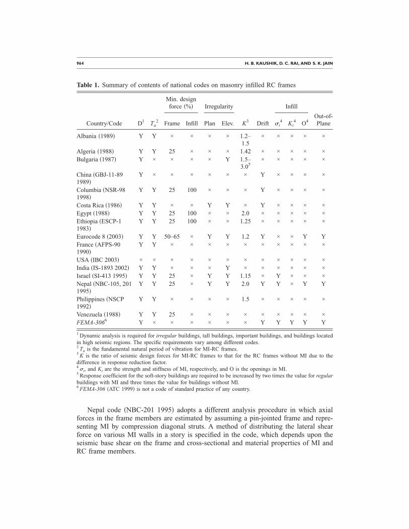
Nepal code �NBC-201 1995� adopts a different analysis procedure in which axialforces in the frame members are estimated by assuming a pin-jointed frame and repre-senting MI by compression diagonal struts. A method of distributing the lateral shearforce on various MI walls in a story is specified in the code, which depends upon theseismic base shear on the frame and cross-sectional and material properties of MI andRC frame members.
Table 1. Summary of contents of national codes on masonry infilled RC frames
Country/Code D1 Ta2
Min. designforce �%� Irregularity
K3 Drift
Infill
Out-of-PlaneFrame Infill Plan Elev. �i
4 Ki4 O4
Albania �1989� Y Y × × × × 1.2–1.5
× × × × ×
Algeria �1988� Y Y 25 × × × 1.42 × × × × ×Bulgaria �1987� Y × × × × Y 1.5–
3.05× × × × ×
China �GBJ-11-891989�
Y × × × × × × Y × × × ×
Columbia �NSR-981998�
Y Y 25 100 × × × Y × × × ×
Costa Rica �1986� Y Y × × Y Y × Y × × × ×Egypt �1988� Y Y 25 100 × × 2.0 × × × × ×Ethiopia �ESCP-11983�
Y Y 25 100 × × 1.25 × × × × ×
Eurocode 8 �2003� Y Y 50–65 × Y Y 1.2 Y × × Y YFrance �AFPS-901990�
Y Y × × × × × × × × × ×
USA �IBC 2003� × × × × × × × × × × × ×India �IS-1893 2002� Y Y × × × Y × × × × × ×Israel �SI-413 1995� Y Y 25 × Y Y 1.15 × Y × × ×Nepal �NBC-105, 2011995�
Y Y 25 × Y Y 2.0 Y Y × Y Y
Philippines �NSCP1992�
Y Y × × × × 1.5 × × × × ×
Venezuela �1988� Y Y 25 × × × × × × × × ×FEMA-3066 Y × × × × × × Y Y Y Y Y
1 Dynamic analysis is required for irregular buildings, tall buildings, important buildings, and buildings locatedin high seismic regions. The specific requirements vary among different codes.2 Ta is the fundamental natural period of vibration for MI-RC frames.3 K is the ratio of seismic design forces for MI-RC frames to that for the RC frames without MI due to thedifference in response reduction factor.4 �i, and Ki are the strength and stiffness of MI, respectively, and O is the openings in MI.5 Response coefficient for the soft-story buildings are required to be increased by two times the value for regularbuildings with MI and three times the value for buildings without MI.6 FEMA-306 �ATC 1999� is not a code of standard practice of any country.
CODE APPROACHES TO SEISMIC DESIGN OF MASONRY-INFILLED RC FRAMES 965
EMPIRICAL FORMULAE FOR NATURAL PERIOD
Natural periods of vibration of buildings depend upon their mass and lateral stiff-ness. Presence of non-isolated MI walls in buildings increases both the mass and stiff-ness of buildings; however, the contribution of latter is more significant. Consequently,the natural periods of an MI-RC frame are normally lower than that of the correspondingbare frame. Therefore, the seismic design forces for MI frames are generally higher thanthose for the bare frames. Although, all national codes explicitly specify empirical for-mulae for the fundamental natural period calculations of bare RC frames, only a fewspecify the formulae for MI-RC frames.
Several codes—IS-1893 �2002�; NBC-105 �1995�; NSR-98 �1998�; Egyptian code�1988�; Venezuelan code �1988�; Algerian code �1988�; ESCP-1 �1983�—suggest usingan empirical formula given by Equation 1 to calculate the natural period of MI-RCframes, Ta.
Ta =0.09h�d
units� Ta in s
h,d in m� �1�
where h is the height of the building and d the base dimension of building at the plinthlevel along the considered direction of the lateral force.
For Ta estimation, French code �AFPS-90 1990� recommends using the most unfa-vorable of Equation 1 and the following equation that is specified for masonry buildings:
T = 0.06h�d� h
2d + hunits:�T in s �2�
In Equations 1 and 2, total base width of buildings is used to calculate Ta, which maynot be appropriate. For example, d will be equal to the total base dimension for all theframes in Figure 2 irrespective of the distribution of MI in the frame. However, forframe in Figure 2c, it is more appropriate to consider d� as the effective base width,rather than total width d of the building. Therefore, Equations 1 and 2 may not estimatecorrect Ta values for different frames shown in Figure 2.
Empirical formula suggested by the Costa Rican code �1986� for MI-RC framebuildings is given by
Ta = 0.08N �3�
where N is number of stories in the building. A flat 20% reduction from that of bareframe �Ta=0.1N� is specified to account for the increased stiffness of frames due topresence of MI.
According to the Israeli seismic code �SI-413 1995�, Ta is determined as follows:
Ta = 0.049h0.75 �4�
In addition, Israeli code recommends that natural period calculated by any structural dy-namics method shall not be larger than the following:

966 H. B. KAUSHIK, D. C. RAI, AND S. K. JAIN
Ta = 0.068h0.75 �5�
This requirement ensures that the seismic design base shear is not less than 80% of thebase shear determined using the period obtained by the empirical relation given byEquation 4.
According to the Algerian code �1988�, Ta is taken as the smaller value between thevalues given by Equation 1 and the following expression:
Ta = 0.05h0.75 �6�According to the empirical Equations 1–6 of various codes, Ta is not a function of
amount of infills in different stories and their distribution along the height. Therefore,Equations 1–6, when used independently, will estimate same Ta values for differentframes shown in Figure 2. A few other codes �Eurocode 8 2003, NSR-98 1998, andNSCP 1992� recommend estimating Ta using a more realistic approach, which is dis-cussed below.
Eurocode 8 �2003� recommends the following equations for buildings up to 40 mhigh:
Ta = Cth0.75 �7�
where
Ct =0.075�Ac
�8�
and
Ac = Ai�0.2 +lwi
h�2
;lwi
h� 0.9 units:�Ac,Ai in m2
lwi in m� �9�
where Ct is the correction factor for MI, which is more for a flexible building, Ac is thecombined effective area of MI in the first story, Ai is the effective cross-sectional area ofwall i in the first story, and lwi is length of the wall i in the first story in the considereddirection.
An older version of the Columbian code �NSR-84 1984� recommended Equation 1for estimating Ta with the following expression for d that includes distribution of MI inframes:
d = ds maxs=1
NS � ds
ds max�2
units:�d,ds,ds max in m �10�
where ds is the length of a segment of wall, ds max is the length of the largest segment ofwall, and Ns is the number of segments of wall in the considered direction. Since Equa-tion 10 considers the amount of MI present in the frame, Ta can be estimated with betteraccuracy than that given by Equation 1. In the latest version of this code �NSR-98 1998�,

CODE APPROACHES TO SEISMIC DESIGN OF MASONRY-INFILLED RC FRAMES 967
Equations 7 and 8 are recommended for Ta calculations with Ct restricted to a maximumvalue of 0.07 and a new formula for Ac as given below:
Ac = Ai�0.02 + � lwi
h�2� ;
lwi
h� 0.9 �11�
The Philippine code �NSCP 1992� has specified Equation 7 for Ta, where Ct is taken as
Ct =0.03048
�Ac
�12�
and where Ac is defined by the following expression:
Ac = Ai�0.2 + � lwi
h�2� ;
lwi
h� 0.9 �13�
Ratio lwi /h can become very large for squat-type buildings in which the length of abuilding is large in comparison to its height. Therefore, an upper limit of 0.9 on lwi /h isspecified in Equations 9, 11, and 13 to prevent computation of unrealistically larger val-ues of Ac. There is no upper limit on Ct in Equations 8 and 12 recommended by Euro-code 8 and Philippine code, respectively. Ct can become unrealistically high for openfirst-story buildings when Ac=0 �Figure 2b�. This may imply that open first-story build-ings are not permitted by Eurocode 8 and Philippine code; however, it is not clearlymentioned in these codes.
Amount of MI in the first story greatly influences Ta, while MI in the upper storiessimply adds to the total mass of frames, and its contribution to the overall stiffness isconsiderably smaller. Equation 7 used by Eurocode 8, Columbian code, and Philippinecode require details of MI only in the first story. Consequently, this Ta estimation may bemore accurate when compared with other empirical equations; however, Equation 7 isnot valid for an open first-story frame unless there is an upper limit on Ct, as specifiedin the Columbian code.
All the above empirical equations for Ta have certain limitations; therefore, a fewcodes �Eurocode 8 2003; NSR-98 1998; Costa Rican code 1986; Venezuelan code 1988;NSCP 1992; Algerian code 1988� recommend the use of Rayleigh formula for Ta cal-culations:
Ta = 2� i=1
N
Wi�ei2
gi=1
N
Fi�ei
units:�Wi in kg
Fi in N
g in m/s2
�ei in m� �14�
where Wi, �ei, and Fi are the seismic weight, elastic displacement, and seismic force,respectively, at level i. �ei is calculated in the first cycle of analysis using Ta from Equa-tion 1 or by any other empirical formulae. A modified Rayleigh formula is also proposed
968 H. B. KAUSHIK, D. C. RAI, AND S. K. JAIN
by Eurocode 8 and Algerian code to estimate Ta:
Ta = 2�� units:�� in m �15�
where � is the lateral displacement at the top of the building due to the gravity loadsapplied horizontally; as a result, � depends upon the distribution of MI in the buildingframe. Rayleigh formula is based on the method of structural dynamics, which includesthe mass and stiffness of all structural members. The codes generally require Ta given byRayleigh formula not to exceed by more than 20–30% of values obtained from empiricalformulae.
In reality, empirical Ta may be more reliable than Ta computed using methods ofstructural dynamics, because there are considerable uncertainties in modeling a buildingfor dynamic analysis, such as stiffness contribution of nonstructural elements and MI,modulus of elasticity of concrete and masonry materials, and area and moment of inertiaof participating structural members. These uncertainties may give rise to unduly largenatural periods and result in lower design seismic forces. Therefore, most of the nationalcodes have put an upper limit on Ta values obtained by Rayleigh method to safeguardagainst unrealistically lower values of design seismic forces.
LATERAL LOAD SHARING BETWEEN INFILL AND FRAME
The combined behavior of MI-RC frames is such that the total seismic design forceis resisted in proportion to the lateral stiffnesses of the RC frame and MI walls at allstory levels. MI walls, which are normally very stiff initially, attract most of the lateralforces, but may fail prematurely because of the brittle behavior. In such cases, RCframes must have sufficient backup strength to avoid the collapse of the structure.
Eurocode 8 �2003� requires the RC frames to resist full vertical loads and at least50–65% of the total lateral loads on buildings. The Columbian �NSR-98 1998�, Egyptian�1988�, and Ethiopian �ESCP-1 1983� codes also require that MI should resist full de-sign lateral seismic loads without any assistance from the RC frame. In such cases, pro-visions must be made to structurally connect MI walls to the surrounding RC frame. TheAlgerian code �1988� requires MI walls to carry at the most 20% of the total verticalloads of the building.
According to most codes, MI is not expected to carry any gravity loads other than itsself-weight. The contribution of MI in resisting the lateral loads can be substantial. How-ever, to safeguard against an RC frame being designed for a very low seismic force, theframe alone is required to be designed to independently resist at least 25% of the designseismic forces in addition to the forces due to vertical loads �Table 1�.
PLAN IRREGULARITIES
Plan irregularities are introduced into buildings because of asymmetric placement ofMI walls, thus increasing shear demand in RC frame members, especially columns. Al-though, national codes mention torsional irregularity, only a few address the problem inthe context of MI, e.g., Eurocode 8 �2003�, NBC-201 �1995�, Costa Rican code �1986�,and SI-413 �1995�.

CODE APPROACHES TO SEISMIC DESIGN OF MASONRY-INFILLED RC FRAMES 969
According to Eurocode 8 �2003�, slight plan irregularities may be taken into accountby doubling the accidental eccentricity. In case of severe plan irregularities due to ex-cessive unsymmetrical placement of MI walls, three-dimensional analysis is requiredconsidering stiffness distribution related to the uncertain position of MI. In addition, asensitivity analysis is required for the position and properties of MI by disregarding oneout of three or four MI panels in a planar frame, especially on the more flexible sides.Accidental eccentricity is assumed to take care of approximations in computation of ec-centricity, possible relocation of the center of mass due to changes in its usage duringservice life of buildings, and probable torsional component of ground motion.
In the Nepal code �NBC-201 1995�, eccentricity between center of mass and centerof rigidity along each principal direction is limited to 10% of the building dimensionalong that direction. The above requirement may be satisfied by adjusting thicknesses ofwalls. According to the Costa Rican code �1986�, eccentricity in each direction must notexceed 5% of the total dimension in that direction. Maximum allowed eccentricity forirregular structures is limited to 30% of the plan dimension in any of the directions.According to the Israeli code �SI-413 1995�, eccentricity in each direction is restricted to10% of the building dimension along that direction. If this condition is not satisfied, cen-ter of rigidity shall be calculated including the stiffness of MI.
A few codes take cognizance of the added torsional forces that may develop in theframe members due to plan irregularity introduced by asymmetrical placement of MIwalls. In such cases, the codes have put a restriction on the amount of plan eccentricitythat a building can have, because the effect of eccentricity is greater under dynamic con-ditions than that is calculated for static conditions.
VERTICAL IRREGULARITIES
Vertical irregularities are introduced into MI-RC frames due to reduction or absenceof MI in a particular story compared to adjacent stories, e.g., buildings with parkingspace in the first story and MI on upper stories. In general, this gives rise to mass, stiff-ness, and strength irregularities along height of buildings. Vertical irregularities in thebottom stories make the beams and columns of those stories more susceptible to damageor failure. A few national codes penalize beams and/or columns of the irregular stories,as they are required to be designed for higher seismic forces to compensate for the re-duction in the strength due to absence of MI in the irregular stories.
The Indian seismic code �IS-1893 2002� requires members of the soft story �storystiffness less than 70% of that in the story above or less than 80% of the average lateralstiffness of the three stories above� to be designed for 2.5 times the seismic story shearsand moments, obtained without considering the effects of MI in any story. The factor of2.5 is specified for all the buildings with soft stories irrespective of the extent of irregu-larities; and the method is quite empirical. The other option is to provide symmetric RCshear walls, designed for 1.5 times the design story shear force in both directions of thebuilding as far away from the center of the building as feasible. In this case, the columnscan be designed for the calculated story shears and moments without considering the
970 H. B. KAUSHIK, D. C. RAI, AND S. K. JAIN
effects of MI. Alternatively, the code requires nonlinear dynamic analysis of such build-ings considering the mass and stiffness of MI and inelastic deformations in all structuralmembers.
Eurocode 8 �2003� recommends increasing the resistance of columns in the less-infilled story in proportion to the amount of deficit in strength of MI. In the older versionof Eurocode 8 �1996�, increase in design forces was sought in beams and columns of theconcerned story. However, further research �Fardis and Panagiotakos 1997� has shownthat increasing the beam resistance would further increase the seismic demands on thecolumns, thus seismic design forces in only columns are increased by a factor � givenby
� = 1 +�VRW
VEd
� q units:��VRW in N
VED in N� �16�
where �VRW is the total reduction in lateral resistance of MI in a story compared to thestory above, and VEd is the sum of seismic shear forces acting on all structural verticalelements of the story concerned. The behavior factor, q, which accounts for the energydissipation capacity of the structure, varies from a minimum value of 1.5 to 4.68 de-pending upon the building systems, ductility classes, and plan regularity in the building.The design forces are not required to be increased if the factor � is less than 1.1.
Maximum vertical irregularities allowed by Eurocode 8 �2003� in buildings are suchthat � is never more than 4.68, which is larger than the factor 2.5 given in the Indiancode �IS-1893 2002�. Also, � is applied only to columns of the soft story, whereas in theIndian code, both beams and columns of the soft story are required to be designed forincreased forces. Eurocode 8 �2003� does not clearly mention whether the buildings withopen first story are permitted; it only restricts the value of �.
Eurocode 8 �2003� requires adequate confinement in the form of shear reinforcementalong the full height of the first-story columns because of the particular vulnerability ofMI in the first story. Confinement along full column height is also required in case offrames containing MI with partial heights to reduce damage due to the short columneffect. Similar confinement is also needed if MI walls are present on only one side of acolumn along a particular direction �e.g., corner columns�.
According to the Bulgarian code �1987�, members of the soft stories �story stiffnessless than half the stiffness of the adjacent stories� are required to be designed for in-creased forces by introducing a coefficient while calculating the design forces. The valueof coefficient for regular RC frames with MI is 0.3 as compared to a value of 0.2 for thebare frames, and the coefficient for the RC frames with a soft story is 0.6. Therefore, thesoft-story members are required to be designed for three times the design seismic forcesfor corresponding regular bare frames �Table 1�. For buildings with asymmetrically dis-tributed masses, the code requires that analyses be done for the most unfavorable direc-tion of the seismic excitation.
Costa Rican code �1986� requires that all structural-resisting systems must be con-tinuous from the foundation to the top of buildings, and stiffness of a story must not be

CODE APPROACHES TO SEISMIC DESIGN OF MASONRY-INFILLED RC FRAMES 971
less than 50% of that of the story below. Also, the weight of two adjacent stories mustnot differ by more than 15%, except at the roof level and at those stories located in thefirst 20% of the height of tall buildings. These clauses are intended to help reduce theadverse effects of the vertical irregularities in buildings.
According to the Israeli code �SI-413 1995�, a flexible �soft� story is that story whoselateral stiffness is less than 70% of that of the story above, or less than 80% of the av-erage stiffness of the three stories above, and which contains less than half the length ofwalls �with thickness of 150 mm or more� as compared to the story above it, in at leastone of its principal directions. Weak story is defined as a story with lateral shear capac-ity in a direction less than 80% of that of the story above in the same direction.
Israeli code allows a flexible �soft� or a weak story, including open first-story build-ings, in buildings with low or medium ductility levels only, which correspond to thebuildings of little or moderate importance only. The design forces for the flexible orweak story members, and for the members in the story above and below, are required tobe increased by a factor 0.6R. The response reduction factor, R, for the building systemis discussed in the next section. For MI-RC frame buildings, R is 3.5 for low ductilitylevel, and 5.0 for medium ductility level. Therefore, beams and columns of the flexibleor weak story, and also of the two adjacent stories, are required to be designed for atleast 2.1–3.0 times the actual design forces for the irregular story, depending upon theductility level of the building. Confinement in columns in the flexible or weak story, andin the story above and below, is required to be increased such that the maximum spacingof shear reinforcement �min. 8 mm diameter� shall not exceed 100 mm throughout theheight of columns. In addition, the overlapping length of column longitudinal bars in theflexible or weak story, and in the two adjacent stories is required to be 30% more thanthat for the corresponding regular columns.
Israeli code allows construction of an extremely weak story, whose shear resistanceis less than 65% of that of the story above, in buildings with height up to 2 stories or9 m, whichever is less. The height restriction is waived if the combined shear resistanceof the weak story and the stories above and below is at least equal to 0.75R times theseismic design base shear for the building. In any case, members of an extremely weakstory and two adjacent stories are required to be designed for the increased forces�0.6R�, as discussed in the previous paragraph.
According to the Nepal code �NBC-201 1995�, at least two lateral load–resistingwalls shall be used in each principal direction at any level in a building. At least 20% ofthe total length of the walls in the x direction shall be placed in each Area 1 and Area 2,and in the y direction in each Area 3 and Area 4, as shown in Figure 3. In each principaldirection, the ratio of lumped mass of each story to the sum of thicknesses of walls in-cluding plaster finish in the story shall not be more than 125% of the same ratio for anyhigher story except at the roof level. This provision keeps a check on the plan and ver-tical irregularities arising in buildings due to unsymmetrical placement of MI.
Most national codes do recognize the vulnerability of frame members of the storiesthat are rendered soft/weak due to the absence or reduction of MI. These codes requireincreasing the seismic design forces of the concerned story members several times,

972 H. B. KAUSHIK, D. C. RAI, AND S. K. JAIN
varying from 1.5 to 4.68 times, depending upon the extent of irregularities, building sys-tems, ductility, and energy dissipation capacity. In some buildings, it is not feasible toincrease capacity of the columns in a soft/weak story. Therefore, the Indian code �IS-1893, 2002� recommends providing symmetric RC shear walls, designed for 1.5 timesthe seismic design forces, in the weak/soft story, preferably on the periphery of build-ings.
RESPONSE REDUCTION FACTOR
Elastic force resultants in RC frame members are reduced by an appropriate value ofR to account for overstrength, redundancy, and ductility in the structure. It is difficult tocompare R values across different codes because of significant differences in the designphilosophies, and safety and load factors used on the final design values. Therefore, Rvalues are compared for different building systems within a particular code only. Theratio of seismic design forces for frames with MI to frames without MI, due to the dif-ference in R as specified by various codes, is given in Table 1. R value for MI-RC framesis generally less than that for bare frames, thus most codes require MI-RC frames to bedesigned for higher force levels than the corresponding bare frames �about 1.15 to 3.0times�.
In Eurocode 8 �2003�, behavior factors are specified for different types of buildingsystems, such that vertically irregular frames are required to be designed for 1.2 timesthe design forces for corresponding regular frames. The code does not differentiate be-tween the behavior factors for RC frames with or without MI.
LATERAL DISPLACEMENT AND INTERSTORY DRIFT
Lateral deformations at various levels in MI-RC frame buildings depend upon thedistribution of MI walls in buildings. If more walls are present at the base, lateral de-formations will be less and evenly distributed along the height of buildings. On the otherhand, if more walls are present on the upper stories, then lateral deformations will be
Figure 3. Plan of a typical building showing requirement of minimum 20% of the total lengthof lateral load–resisting walls along both x and y directions to be placed in each of the externalframes in both directions �NBC-201 1995�.

CODE APPROACHES TO SEISMIC DESIGN OF MASONRY-INFILLED RC FRAMES 973
concentrated at the bottom, where stories are lesser infilled. Lateral deformations andinterstory drift will also depend upon the ductility and damping of buildings.
Chinese code �GBJ-11-89 1989� has provisions to control the deformability ofMI-RC frames. Seismic deformations must be checked for the limit state of deformabil-ity. Elastic story relative displacement, �Ue, caused by the design value of frequent-earthquake action should not exceed the limit given by
�Ue � ��e�H units:��Ue,H in m
�e in rad� �17�
where �e is the elastic drift taken as 1/550 for frames considering the stiffness of MI.Elasto-plastic story relative displacement ��Up� at weak locations caused by rare largeearthquakes is limited by
�Up � ��p�Hw units:��Up,Hw in m
�p in rad� �18�
where �p is the elasto-plastic drift with a value of 1/50 �increased by 20% for ductilecolumns�, and Hw is height of the weak story. Such buildings shall not have any abruptchange in story rigidity, and height shall not be more than 12 stories. By restricting elas-tic and elasto-plastic relative story displacement in MI-RC frames, an attempt has beenmade to reduce the brittle and out-of-plane failure of MI.
A few national codes, such as Eurocode 8 �2003�, NBC-105 �1995�, NSR-98 �1998�,and Costa Rican code �1986� have restricted the interstory drift ratio for MI-RC framesto about 1%. These drift ratios are calculated using displacements obtained from elasticforces, which are amplified. FEMA-306 �ATC 1999� recommends the following inter-story drift limit states for different solid panels: for brick masonry, 1.5%; for groutedconcrete block masonry, 2.0%; and for ungrouted concrete block masonry, 2.5%. How-ever, there is a concern that these values are too large and further experimental studiesare needed to verify these limit states.
STRENGTH OF MASONRY INFILL
Strength of MI does not have any direct implications on the ultimate strength of duc-tile RC frames; however, in some cases, failure modes of MI control the failure modes ofnonductile RC frames. Failure mode of MI depends upon relative strength of MI in dif-ferent actions, like compression, shear, etc. For example, if RC columns are not suffi-ciently confined with shear reinforcement, then shear-sliding failure mode of MI along abed joint may trigger shear failure of columns.
As per Eurocode 8 �2003�, shear capacity of columns is required to be checked forshear forces generated by the diagonal strut action of MI by considering the verticalcomponent of the width of strut as the contact area between RC frame and MI. Recom-mended strut width is an unspecified fraction of the panel diagonal length. Minimumwall thickness of 240 mm and maximum slenderness ratio �height/thickness� of 15 isspecified for MI. Nepal code �NBC-201 1995� also requires MI to be modeled as diag-

974 H. B. KAUSHIK, D. C. RAI, AND S. K. JAIN
onal struts, without specifying their cross-sectional properties. A minimum wall thick-ness of half brick is allowed to be used as infill.
According to the Israeli code �SI-413 1995�, MI of thickness 150 mm or more areconsidered to resist the seismic story shear force, and total story resistance is given by
VR = 10� Ac�fvd + 0.4� Am�fmk units:�VR in N
Ac,Am in mm2
fvd,fmk in MPa� �19�
where Ac and Am are total cross-sectional areas of RC columns and MI, respectively,along the direction considered, fvd is the design strength of concrete in shear, and fmk isthe characteristic shear strength of MI, which may be taken as 0.2 MPa for walls withmortar of at least 10 MPa compressive strength, and 0.1 MPa for walls with weakermortar.
FEMA-306 recommends the following equation to calculate the effective width ofdiagonal compression strut a, which can be used in the strength calculation of MI:
a = 0.175��1hcol�−0.4rinf units:�a,hcol,rinf in in. �20�
where hcol is the column height, rinf is the diagonal length of the MI panel, and �1 isgiven by
�1 = �Emetinf sin 2�
4EfeIcolhinf�0.25
units:��1 in in.−1
Eme,Efe in psi
tinf,hinf in in.
� in rad
Icol in in.4� �21�
where Eme and Efe are expected modulus of elasticity of masonry �secant modulus ofelasticity between 5% and 33% of masonry prism strength� and frame material, respec-tively. In the absence of tests, recommended value of Eme is specified as 550 times theprism strength of masonry �fme� �. In Equation 21, tinf is the actual thickness of MI in con-tact with frame, � is the inclination of diagonal strut with horizontal, Icol is the momentof inertia of column, and hinf is the height of MI panel. Thickness of equivalent strut istaken to be equal to actual thickness of the wall.
FEMA-306 identifies four possible failure modes for MI that also give an indicationof potential crack and damage patterns in MI. The failure modes are sliding-shear fail-ure, compression failure, diagonal tension cracking, and general shear failure. Equationsgiven in FEMA-306 to calculate strength corresponding to each failure mode are sum-marized in the Appendix. These equations must be used with caution as their furtherexperimental verification may be necessary.
In addition to these failure modes of MI, RC frame may fail due to the flexural fail-ure of beams and/or columns due to yielding of tension steel, shear failure of beams

CODE APPROACHES TO SEISMIC DESIGN OF MASONRY-INFILLED RC FRAMES 975
and/or columns, and shear failure and bond failure of beam-column joints. Strength as-sociated with these failure modes of RC frames members is generally calculated fromdifferent RC codes.
Effect of Openings in Masonry Infill on Strength
Door and window openings in MI are provided because of functional and ventilationrequirements of buildings. Presence of openings in MI changes the actual behavior ofRC frames because of reduction in lateral strength and stiffness. Most national codes, ingeneral, do not discuss the effects of openings on the strength and stiffness of MI-RCframes.
As per Eurocode 8, only the solid walls or walls with a single door or window open-ing are assumed to be imparting any significant strength to the structure. Large openingsare required to be framed with RC elements across the full length and thickness of walls.Vertical RC elements of at least 150 mm dimension are required at both sides of anyopening larger than a 1.5 m2 area. Longitudinal steel in the element shall not be lessthan 300 mm2 or 1% of the cross-sectional area of the element. Shear reinforcement inthe form of stirrups of at least 5 mm diameter is required with a minimum spacing of150 mm.
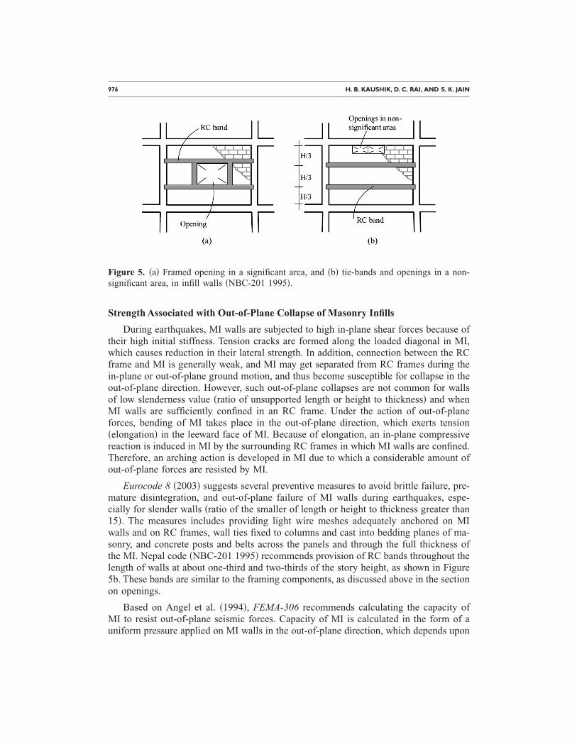
According to the Nepal code �NBC-201 1995�, only those walls with an openingarea less than 10% of the gross panel area are considered as resisting seismic loads.Openings shall be outside the restricted zone �Figure 4�, and if these openings are lo-cated inside the middle two-thirds of a panel, then they need to be strengthened by pro-viding RC elements around them �Figure 5a�. RC tie beams at both the top and bottomof openings along the full length and width of the wall, and vertical elements on bothsides of the opening shall be provided with longitudinal reinforcement of two bars of8 mm diameter. Shear reinforcement in the form of minimum 6 mm diameter bars atevery 150 mm is required in the elements. Such strengthening elements are not requiredfor openings in a nonsignificant area �Figure 5b�.
Figure 4. Possible location of openings in infill walls �NBC-201 1995�.
976 H. B. KAUSHIK, D. C. RAI, AND S. K. JAIN
Strength Associated with Out-of-Plane Collapse of Masonry Infills
During earthquakes, MI walls are subjected to high in-plane shear forces because oftheir high initial stiffness. Tension cracks are formed along the loaded diagonal in MI,which causes reduction in their lateral strength. In addition, connection between the RCframe and MI is generally weak, and MI may get separated from RC frames during thein-plane or out-of-plane ground motion, and thus become susceptible for collapse in theout-of-plane direction. However, such out-of-plane collapses are not common for wallsof low slenderness value �ratio of unsupported length or height to thickness� and whenMI walls are sufficiently confined in an RC frame. Under the action of out-of-planeforces, bending of MI takes place in the out-of-plane direction, which exerts tension�elongation� in the leeward face of MI. Because of elongation, an in-plane compressivereaction is induced in MI by the surrounding RC frames in which MI walls are confined.Therefore, an arching action is developed in MI due to which a considerable amount ofout-of-plane forces are resisted by MI.
Eurocode 8 �2003� suggests several preventive measures to avoid brittle failure, pre-mature disintegration, and out-of-plane failure of MI walls during earthquakes, espe-cially for slender walls �ratio of the smaller of length or height to thickness greater than15�. The measures includes providing light wire meshes adequately anchored on MIwalls and on RC frames, wall ties fixed to columns and cast into bedding planes of ma-sonry, and concrete posts and belts across the panels and through the full thickness ofthe MI. Nepal code �NBC-201 1995� recommends provision of RC bands throughout thelength of walls at about one-third and two-thirds of the story height, as shown in Figure5b. These bands are similar to the framing components, as discussed above in the sectionon openings.
Based on Angel et al. �1994�, FEMA-306 recommends calculating the capacity ofMI to resist out-of-plane seismic forces. Capacity of MI is calculated in the form of auniform pressure applied on MI walls in the out-of-plane direction, which depends upon
Figure 5. �a� Framed opening in a significant area, and �b� tie-bands and openings in a non-significant area, in infill walls �NBC-201 1995�.

CODE APPROACHES TO SEISMIC DESIGN OF MASONRY-INFILLED RC FRAMES 977
strength of masonry, slenderness ratio, and damage sustained in MI walls and surround-ing columns due to in-plane seismic forces.
STIFFNESS OF MASONRY INFILL
MI walls are laterally much stiffer than RC frames, and therefore, the initial stiffnessof the MI-RC frames largely depends upon the stiffness of MI. Stiffness of MI-RCframes significantly depends on the distribution of MI in the frame; generally, theMI-RC frames with regular distribution of MI in plan as well as along height are stifferthan the irregular MI-RC frames. Lateral stiffness of MI-RC frames reduces with thepresence of openings in infills; however, this issue has not been addressed by the na-tional codes.
Eurocode 8 �2003�, Nepal code �NBC-201 1995�, and FEMA-306 recommend mod-eling the MI as equivalent diagonal struts. However, Eurocode 8 and Nepal code do notspecify the width of strut. FEMA-306 recommends Equation 20 to calculate the width ofstrut for use in stiffness calculations; however, experimental research by Al-Chaar�2002� has reported that Equation 20 can estimate only the lower-bound stiffness valuesof MI.
Nepal code specifies the modulus of elasticity of MI as 2,400 to 3,000 MPa for vari-ous grades of mortar. On the other hand, FEMA-306 recommends using modulus ofelasticity as 550 times the masonry prism strength in the absence of tests. As per FEMA-306, the only MI walls assumed to provide stiffness are those that are in full contact withRC frames, or those that are structurally connected to RC frames.
SHORTCOMINGS IN NATIONAL CODES
The present paper has illustrated several shortcomings of various national codes onissues related to seismic design of MI-RC frame buildings. Major problem areas in vari-ous national codes needing further attention may be summarized as follows:
1. Empirical estimation of natural period addresses very simple and regularMI-RC frames and does not cover the frames rendered irregular because of un-symmetrical distribution of MI. Because of practical reasons, most RC build-ings become irregular when MI walls are added in RC frames. Therefore, mostof the empirical equations may not estimate the natural periods of such build-ings with sufficient accuracy.
2. Enhanced design of weak/soft-story frame members is done in different nationalcodes based on empirical or semi-empirical relations. Very limited literature isavailable in support of these relations. Hence there is an urgent need for moreresearch in this area.
3. Strength and stiffness of MI are among the most important concerns related toMI-RC frame buildings, yet national codes are not very specific on these issues.The presence of openings in MI walls and vulnerability in the out-of-plane di-rection further complicates the matter. Only limited research is available to ad-dress issues related to reduction in strength and stiffness of MI because of the

978 H. B. KAUSHIK, D. C. RAI, AND S. K. JAIN
presence of openings, and to assess the strength associated with the out-of-planecollapse of MI.
4. Response reduction factor and allowable story drift control the seismic designforces and deformability requirements for buildings, respectively. There is noconsensus in various national codes on values of response reduction factor,which reflects that more research is needed on reliable estimation of strengthand ductility of such buildings. Similarly, there is an ambiguity over the speci-fications in various national codes regarding allowable story drift in suchbuildings.
Clearly, a substantial amount of research is required to enhance our understanding ofthese widely used structures, and to overcome the shortcomings in the national codesassociated with the seismic design of such structures.
SUMMARY AND CONCLUSIONS
MI in RC frames acts as a diaphragm in vertical plane that imparts significant lateralstrength and stiffness to RC frames under lateral loads. Infilled frames also tend to besubstantially stronger, but less deformable, than otherwise identical bare frames. In sym-metric buildings with vertically continuous infilled frames, the increased stiffness andstrength may protect a building from damage associated with excessive lateral drift orinadequate strength. Because of its higher stiffness, infill panels may attract significantlygreater forces that may lead to premature failure of infill, and possibly of the wholestructure. Therefore, it is essential for designers to consider the effects of infills in thedesign of RC buildings.
In the paper, seismic design provisions in various national codes for MI-RC frameshave been reviewed and compared. As shown in Table 1, there is no single code thatcontains all the relevant information required for the seismic design of such buildings.Most of the codes agree that MI-RC frame buildings require special treatment, and theyspecify clauses on several important issues related to such buildings. However, the codesdiffer greatly in specifications of the individual clauses.
Various codes recommend simplified static analysis methods for regular buildings,and detailed three-dimensional dynamic analysis methods for irregular buildings. Sev-eral empirical formulae are suggested to estimate the natural period of MI-RC frames,which have their own shortcomings. Thus some codes recommend using Rayleigh for-mula to calculate the period more accurately. Most of the codes require that the periodsestimated by Rayleigh formula are not more than 20–30% of those given by empiricalformulae.
Although MI attracts most of the lateral forces coming on buildings, RC frames musthave sufficient strength to prevent the premature failure of buildings in case of failure ofmasonry walls because of their brittle behavior. Thus most codes recommend designingRC frames to independently resist at least 25% of the design seismic base shear.
CODE APPROACHES TO SEISMIC DESIGN OF MASONRY-INFILLED RC FRAMES 979
Several codes address the problems associated with plan and vertical irregularities inMI-RC frames. The codes restrict the amount of eccentricity between center of mass andcenter of rigidity to safeguard the building components against the adverse effects ofplan irregularities. In case of vertical irregularities, codes recommend increasing the ca-pacity of irregular story members by 1.5–4.68 times, depending upon the extent of ir-regularities, building systems, ductility of the members, etc.
National codes specify lower values of response reduction factors for MI-RC framebuildings as compared to the buildings without MI, such that MI frames are required tobe designed for 1.15–3 times the design forces for the corresponding bare frames. Lowervalue of response reduction factor is considered for MI-RC frames because of lowerductility and a higher degree of uncertainty and seismic vulnerability associated withMI. A few codes have specified limitations on the elastic and inelastic deformations andinterstory drift ratio of MI-RC frames for damage limitation requirements.
A few codes recommend modeling MI using equivalent diagonal struts; however, therequired sectional properties for the struts are not specified. Strength and stiffness of MIreduces with the presence of openings; however, the issue is not looked upon by anycode. Various ways of reducing the damage in MI due to openings have been discussedin a few codes, e.g., framing the openings using RC elements. Full strength and stiffnessof MI is not utilized when out-of-plane collapse of infills takes place. A few codesspecify limits on slenderness ratio �ratio of length or height to thickness� to prevent out-of-plane failure of masonry infill. Some national codes recommend using light wiremesh and RC tie-bands along the length of walls at various locations to avoid out-of-plane collapse of MI.
Shortcomings of various national codes and recommendations for possible future re-search on MI-RC frames are discussed in the paper. A comprehensive design code forMI-RC frames is urgently needed as a significantly large number of buildings belongs tothis category.
ACKNOWLEDGMENTS
The authors acknowledge the financial assistance provided by the Ministry of Hu-man Resource Development �MHRD�, Government of India, in the research work.
APPENDIX
FEMA-306 recognizes four possible failure modes of MI, and the strength associatedwith each failure mode is discussed in the following:
SLIDING-SHEAR FAILURE
In ductile RC frames, failure of MI with weak mortar joints and strong brick unitsmay take place by sliding through the horizontal bed joint of wall. Initial sliding-shearcapacity of MI is calculated by the Mohr-Coulomb failure criteria given by

980 H. B. KAUSHIK, D. C. RAI, AND S. K. JAIN
Vslide1 = �0 + �y tan �Linftinf = µN units:�
Vslide1 ,N in lbf
0,�y in psi
in rad
Linf in in.� �A1�
where �y is the vertical stress on a MI panel, is the angle of sliding friction of masonryalong a bed joint, and Linf is the length of the panel. 0 is the cohesive capacity of mortarbeds, which, in the absence of data, may be taken as 0.05 times fme90� , where fme90� �psi�is the expected strength of masonry in the horizontal direction, which may be set at 50%of the expected prism strength of masonry, fme� �psi�. µ is the coefficient of sliding fric-tion along the bed joint and N is the vertical load in the masonry panel.
After the cohesive bond in a mortar bed is destroyed �0=0� as a result of cyclicloading, MI still has some ability to resist sliding through shear friction in the bed joints.If lateral deformations are small, then Vslide
1 �0, because �y may only result from theself-weight of panels. However, if the interstory drifts become large, then the boundingcolumns impose a vertical load due to shortening of the height of panels. Vertical short-ening strain � in panels is
� =�
hcol= �d
�d
hcol= �d
2 units:��,�d,hcol in in.
�d in rad� �A2�
where � is the downward movement of the upper beam as a result of the interstory driftangle, �d, and �d is the interstory drift. Axial load on MI can be calculated by
N = �LinftinfEme �A3�
Sliding-shear capacity of MI is then calculated by
Vslide1 = µLinftinfEme�d
2 �A4�
COMPRESSION FAILURE
Failure of MI may take place by compression failure of the equivalent diagonal strutif the mortar joints and brick units are strong and RC frames are sufficiently ductile.Horizontal shear force required for the failure of equivalent diagonal strut is calculatedby
Vc = atinffme90� cos � units:�Vc in lbf �A5�
DIAGONAL TENSION CRACKING
This is not a failure mode; however, it helps other failure modes to propagate. Underlateral in-plane loading, high compressive stresses develop in MI along the loaded diag-onal, and transverse to these compressive diagonal stresses, tension cracks develop inMI. Using the recommendations of Saneinejad and Hobbs �1995�, the cracking shear inMI is given by

CODE APPROACHES TO SEISMIC DESIGN OF MASONRY-INFILLED RC FRAMES 981
Vcr = 2�2tinfhinf�cr cos2 � units:�Vcr in lbf
�cr in psi� �A6�
In the absence of tests results, the cracking capacity of masonry, �cr, which is approxi-mately equal to the cohesive capacity of the mortar beds, may be taken as 0.05 timesfme90� . The cracking capacity, �cr may also be calculated as
�cr = 20�fme� �A7�
GENERAL SHEAR FAILURE OF PANEL
Initial and final contributions of shear carried by MI panels are defined as
Vmi = Avh2�fme� units:�Vmi,Vmf in lbf
fme� in psi
Avh in in.2� �A8�
and
Vmf = 0.3Vmi �A9�
where Vmi is the available initial shear capacity consumed during the first half-cyclic�monotonic� loading, Vmf is the final shear capacity as a result of cyclic loading effects,and Avh is the net horizontal shear area of MI panels. For panels without openings, Avh
is calculated by the total length times the thickness of walls. Lower value among thosegiven by Equations A1 and A8 will be the governing shear strength of infill.
REFERENCES
AFPS-90, 1990. Recommendations for the Redaction of Rules Relative to the Structures andInstallations Built in Regions Prone to Earthquakes, French Association of Earthquake En-gineering, Paris, France.
Al-Chaar, G., 2002. Evaluating Strength and Stiffness of Unreinforced Masonry Structures,Technical Report ERDC/CERL TR-02–1, U.S. Army Corps of Engineers.
Albanian Seismic Code, 1989. Earthquake Resistant Design Regulations, Seismological Center,Academy of Sciences of Albania, Department of Design, Ministry of Construction, Tirana,Albania.
Algerian Seismic Code, 1988. Algerian Earthquake Resistant Regulations, Ministry of Town-planning and Construction, Algiers, Algeria.
Angel, R., Abrams, D., Shapiro, D., Uzarski, J., and Webster, M., 1994. Behavior of ReinforcedConcrete Frames with Masonry Infills, Technical Report UILU-ENG-94–2005, Departmentof Civil Engineering, University of Illinois at Urbana-Champaign, IL.
Applied Technology Council �ATC-43 Project�, 1999. Evaluation of Earthquake Damaged Con-crete and Masonry Wall Buildings—Basic Procedures Manual, prepared for the partnershipfor Response and Recovery, published by the Federal Emergency Management Agency,FEMA-306, Washington D.C.
982 H. B. KAUSHIK, D. C. RAI, AND S. K. JAIN
Bulgarian Seismic Code, 1987. Code for Design of Buildings and Structures in Seismic Re-gions, Bulgarian Academy of Science Committee of Territorial and Town System at theCouncil of Ministers, Sofia, Bulgaria.
Bureau of Indian Standards, 2002. IS-1893, Indian Standard Criteria for Earthquake ResistantDesign of Structures—Part 1: General Provisions and Buildings �Fifth Revision�, NewDelhi, India.
Chinese Academy of Building Research, 1989. Seismic Design Code for Buildings and Struc-tures, GBJ-11–89, Beijing, China.
Costa Rican Seismic Code, 1986. Seismic Code of Costa Rica, Federal College of Engineersand Architects of Costa Rica, San Jose, Costa Rica.
Egyptian Seismic Code, 1988. Regulations for Earthquake Resistant Design of Buildings inEgypt, Egyptian Society for Earthquake Engineering, Cairo, Egypt.
ESCP-1, 1983. Code of Practice for Loading, Ethiopia, Ministry of Urban Development andHousing, Addis Ababa, Ethiopia.
Eurocode 8, 1996. Design Provisions for Earthquake Resistance of Structures—Part 1–3: Gen-eral Rules—Specific Rules for Various Materials and Elements, DD ENV 1998–1-3: Euro-pean Committee of Standardization, Brussels, Belgium.
European Committee of Standardization, 2003. Eurocode 8: Design of Structures for Earth-quake Resistance—Part 1: General Rules, Seismic Actions and Rules for Buildings, prEN1998-1, Brussels, Belgium.
Fardis, M. N., and Panagiotakos, T. B., 1997. Seismic design and response of bare andmasonry-infilled reinforced concrete buildings, Part II: Infilled structures, J. EarthquakeEng. 1 �3�, 475–503.
International Association for Earthquake Engineering �IAEE�, 2004. Regulations for SeismicDesign: A World List—2004, Tokyo, Japan.
International Code Council �ICC�, 2003. International Building Code, Reston, VA.Luft, R. W., 1989. Comparisons among earthquake codes, Earthquake Spectra 5 �4�, 767–789.Moghaddam, H. A., and Dowling, P. J., 1987. The State of the Art in Infilled Frames, ESEE
Research Report No. 87-2, Imperial College of Science and Technology, Civil Eng. Depart-ment, London, U.K.
Murty, C. V. R., and Jain, S. K., 2000. Beneficial influence of masonry infills on seismic per-formance of RC frame buildings, Proceedings, 12th World Conference on Earthquake Engi-neering, New Zealand, Paper No. 1790.
NBC-105, 1995. Nepal National Building Code for Seismic Design of Buildings in Nepal, Min-istry of Housing and Physical Planning, Department of Buildings, Kathmandu, Nepal.
NBC-201, 1995. Nepal National Building Code for Mandatory Rules of Thumb for ReinforcedConcrete Buildings with Masonry Infill, Ministry of Housing and Physical Planning, Depart-ment of Buildings, Kathmandu, Nepal.
NSCP, 1992. National Structural Code of Philippines, Vol. 1, Fourth Edition, The Board ofCivil Engineering of the Professional Regulation Commission, Manila, Philippines.
NSR-84, 1984. Colombian Standards for Seismic Resistant Design and Construction, Bogota,Colombia.
NSR-98, 1998. Colombian Standards for Seismic Resistant Design and Construction, Bogota,Colombia.
CODE APPROACHES TO SEISMIC DESIGN OF MASONRY-INFILLED RC FRAMES 983
NZS-3101, 1995. Code of Practice for the Design of Concrete Structures, Part 1, Standards As-sociation of New Zealand, Wellington, New Zealand.
Paz, M., 1994. International Handbook of Earthquake Engineering: Codes, Programs, and Ex-amples, Chapman and Hall, Inc., New York.
Saneinejad, A., and Hobbs, B., 1995. Inelastic design of infilled frames, J. Struct. Eng. 121 �4�,634–650.
SI-413, 1995. Design Provisions for Earthquake Resistance of Structures, The Standards Insti-tution of Israel, Tel-Aviv, Israel.
SNIP-II-7–81, 1996. Building Code on Construction in Seismic Areas, The Ministry for Con-struction of Russia, Moscow, Russia.
Venezuelan Seismic Code, 1988. Regulations for Earthquake Resistant Buildings, Comision DeNormas Industriales, Covenin, Caracas, Venezuela.
�Received 19 July 2005; accepted 22 December 2005�