coax mapping tester user's guide - viavi solutions inc.s guide coax mapping tester test button...
TRANSCRIPT

User's Guide
www.jdsu.com/know
Coax Mapping Tester

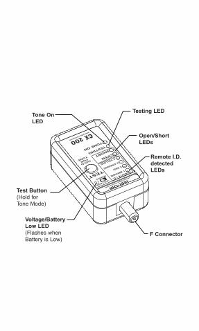
Test Button (Hold for Tone Mode)
Remote I.D. detected LEDs
Voltage/Battery Low LED(Flashes whenBattery is Low)
F Connector
Open/Short LEDs
Testing LEDTone On LED
�
DescriptionThe Coax mapping tester is a small hand held tester designed for CATV and security system installers who test multi-run coax systems terminated with F-connectors or those who wish to map runs to a central bundle. It has the ability to put a tone signal on a coax cable as well as find and identify multiple coax cables connected to a coax splitter. With four unique identifier test terminators, it is ideal for mapping coax installations.
The Coax mapping tester consists of a master unit and four remote terminators (#� Brown, #2 Red, #3 Orange, #4 Yellow). The Coax mapping tester is used to test coax cables with F-connectors or with BNC connectors using the included adapters. The master unit is connected to one end of the coax cable and the remote units are connected to the other end of the coax cables. If there is voltage present, the “Voltage!” light will turn on. Disconnect the tester from the live line and remove voltage source from the coax cable before further testing. With the master and remote(s) connected, push the TEST button. The TESTING LED will flash quickly and the is

2
test performed. If no failures are detected, the remote(s) will be identified in the PASS area by lighting an LED for each remote found (multiple LEDs with DC passing spliters). If no remote is found, or the cable is shorted, the OPEN or SHORT LEDs will light, respectively.
Note: The Coax mapping tester will not test cable runs with AC or DC voltage present. Also it will not test through amplifiers, DC blocking devices or isolation splitters.
3
Instructions for UseTo put TONE on a coax cable push and hold down the TEST button until the TONE LED lights. TONE is now on, and the master unit is transmitting tone on the center pin of the coax cable. The TONE LED will flash indicating that tone mode is on. Tone mode will automatically shut off after approximately 30 minutes. To exit the tone mode, push the test button once. The TONE LED will turn off.
Voltage Present DetectionA positive DC or an AC voltage on the center pin of the connector will cause the “Voltage!” LED to light. Remove tester from line and remove source of voltage from coax cable before doing any further testing.

4
Battery Low Light
When Voltage!/battery low LED flashes replace battery.
Battery ReplacementA 6 volt L�325 �/2AA size battery powers the Coax mapping tester. Battery removal and installation is as follows:
Remove the screw from back of unit using a #� Phillips screwdriver. Carefully open unit.
Remove old battery and dispose of properly.
Install new battery.
Be sure + on battery matches + on battery holder.
Close unit and replace screw, being careful not to over tighten the screw.
�)
2)
3)
4)
5)

5
Models, options & accessories
Order number Description
CX200 Coax mapping tester
CX30Terminators for coax mapping tester - Set of 4 (Brown, Red, Orange, and Yellow)
CX3� Terminator for coax mapping tester - #� Brown
CX32 Terminator for coax mapping tester - #2 Red
CX33 Terminator for coax mapping tester - #3 Orange
CX34 Terminator for coax mapping tester - #4 Yellow
CX35 Batteries - 6 Volt for CX200 - 32 pieces

6
SpecificationsAutomatic Power off:
12 seconds after PASS/FAIL results. 30 minutes in Tone mode.
Minimum cable length for testing:0 meters (0 ft.)
Maximum cable length that can be tested: 1000 meters (3000 ft.) *
Maximum DC cable resistance (Shield + Center Conductor):
100 ohms*Cable Length: Cables vary widely in DC resistance. The distances quoted above is for typical resistance cable. The tester is capable of testing longer runs of low resistance cable. See reference chart below:
Coax Type Beldon P/N
Center +
Shield
Max Length
RG-58A/U 8259 14.9 Ohms/1000ft
2.045km (6710ft)
RG-59/U 9310 24.1 Ohms/1000ft
1.265km (4150ft)
RG-59/U 9259 23.5 Ohms/1000ft
1.297km (4255ft)

�
RG-59/U 8241A 49.7 Ohms/1000ft
628m (2010ft)
RG-59/U 9275 78.5 Ohms/1000ft
398m (1275ft)
Note: The Coax mapping tester will not test cable runs with:Power Amplifiers Directional Line TapIsolation Splitters Power DividersAttenuators Matching Transformers

�
Customer Services This section provides a description of customer services available through JDSU (including returns policies and procedures) and warranty information. Customer Service (Standard Services) Customer Service accompanies the sale of every JDSU product. Customer Service services include:
Technical Assistance (Business Hour) Instrument Repair (Under Warranty Repair, Calibration Services, and Upgrade Services) Immediate Return Authorizations
Technical Assistance Expert business hour technical support is included with your product.
Instrument Repair Our service centers provide repair, calibration, and upgrade services for JDSU equipment. JDSU understands the impact of equipment down time on operations and is staffed to ensure a quick turnaround. Available services include the following:
Product Repair — All equipment returned for service is tested to the same rigorous standards as newly
••
•

�
manufactured equipment. This ensures products meet all published specifications, including any applicable product updates.
Calibration — JDSU’s calibration methods are ISO approved and based on national standards.
Factory Upgrades — Any unit returned for a hardware feature enhancement will also receive applicable product updates and will be thoroughly tested, ensuring peak performance of the complete feature set.
Equipment Return Instructions Please contact your regional Technical Assistance Center to get a Return or Reference Authorization to accompany your equipment. For each piece of equipment returned for repair, attach a tag that includes the following information:
Owner’s name, address, and telephone number. The serial number (if applicable), product type, and model. Warranty status. (If you are unsure of the warranty status of your instrument, contact Technical Assistance.) A detailed description of the
•
•
•
•

�0
problem or service requested. The name and telephone number of the person to contact regarding questions about the repair. The return authorization (RA) number (US customers), or reference number (European Customers).
If possible, return the equipment using the original shipping container and material. If the original container is not available, the unit should be carefully packed so that it will not be damaged in transit; when needed, appropriate packing materials can be obtained by contacting JDSU Technical Assistance. JDSU is not liable for any damage that may occur during shipping. The customer should clearly mark the JDSU-issued RA or reference number on the outside of the package and ship it prepaid and insured to JDSU.
•
•
��
Warranty Information JDSU guarantees that its products will be free of all defects in material and workmanship. This warranty extends for the period of �2 months for test instruments and 3 months for cables from date of manufacture or purchase (proof of purchase required). All product deemed defective under this warranty will be repaired or replaced at JDSU’s discretion. No further warranties either implied or expressed will apply, nor will responsibility for operation of this device be assumed by JDSU.
WEEE Directive ComplianceJDSU has established processes in compliance with the Waste Electrical and Electronic Equipment (WEEE) Directive, 2 002 /�6/EC. This product should not be disposed of as unsorted municipal waste and should be collected separately and disposed of according to your national regulations. In the European Union, all equipment purchased from JDSU after 005 -0� -�3 can be returned for disposal at the end of its useful life. JDSU will ensure that all waste equipment returned
�2
is reused, recycled, or disposed of in an environmentally friendly manner, and in compliance with all applicable national and international waste legislation. It is the responsibility of the equipment owner to return the equipment to JDSU for appropriate disposal. If the equipment was imported by a reseller whose name or logo is marked on the equipment, then the owner should return the equipment directly to the reseller. Instructions for returning waste equipment to JDSU can be found in the Environmental section of JDSU’s web site at www.jdsu.com. If you have questions concerning disposal of your equipment, contact JDSU’s WEEE Program Management team at [email protected].
Document Information
Doc. # TU9813
Revision 501, 06-08
English
www.jdsu.com/know