coatings and pottings-ctea - smta · o small standoff height allows coating to cause lift ......
TRANSCRIPT

© 2004 - 2007© 2004 - 20109000 Virginia Manor Rd Ste 290, Beltsville MD 20705 | 301-474-0607 | www.dfrsolutions.com© 2004 – 2010
Coatings and Pottings – Issues and Challenges
CTEA – May 6, 2014
Presented by:
Greg Caswell – Sr. Member of the Technical Staff

© 2004 - 2007© 2004 - 20109000 Virginia Manor Rd Ste 290, Beltsville MD 20705 | 301-474-0607 | www.dfrsolutions.com
Conformal Coating Options
o Conformal Coating Overview:o Conformal coating is applied to circuit cards to provide a dielectric layer on an electronic board.
o This layer functions as a membrane between the board and the environment.
o With this coating in place, the circuit card can withstand more moisture by increasing the surface resistance or surface insulation resistance (SIR).
o With a higher SIR board, the risk of problems such as cross talk, electrical leakage, intermittent signal losses, and shorting is reduced.
o This reduction in moisture will also help to reduce metallic growth called dendrites and corrosion or oxidation. Conformal coating will also serve to shield a circuit card from dust, dirt and pollutants that can carry moisture and may be acidic or alkaline.
© 2004 - 2007© 2004 - 20109000 Virginia Manor Rd Ste 290, Beltsville MD 20705 | 301-474-0607 | www.dfrsolutions.com
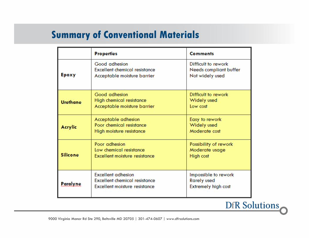
Summary of Conventional Materials
© 2004 - 2007© 2004 - 20109000 Virginia Manor Rd Ste 290, Beltsville MD 20705 | 301-474-0607 | www.dfrsolutions.com
o Automotive: exposure to gasoline vapor, salt spray and brake fluid. both under the hood (e.g. engine management systems), and in passenger compartments (e.g. onboard computers).
o Aerospace: high reliability requirements, rapid compression and decompression, pressurized and depressurized areas.
o Marine: both fresh and salt water environments will attack electronic circuitry, under the dash of high performance boats, to exterior equipment used on larger maritime systems.
o Medical: Tool protection while in storage to prevent corrosion; pacemakers, where it is vital to ensure continuous performance and even food carts in hospitals.
Applications
© 2004 - 2007© 2004 - 20109000 Virginia Manor Rd Ste 290, Beltsville MD 20705 | 301-474-0607 | www.dfrsolutions.com
o The conformal coating material can be applied by:
o brushing
o spraying
o dipping
o Or, due to the increasing complexities of electronic circuit board assemblies being designed and with the 'process window' becoming smaller and smaller, by selectively coating via robot.
How is Conformal Coating Applied?
© 2004 - 2007© 2004 - 20109000 Virginia Manor Rd Ste 290, Beltsville MD 20705 | 301-474-0607 | www.dfrsolutions.com
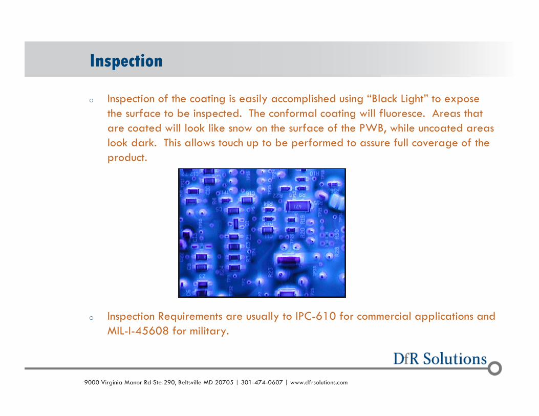
o Inspection of the coating is easily accomplished using “Black Light” to expose the surface to be inspected. The conformal coating will fluoresce. Areas that are coated will look like snow on the surface of the PWB, while uncoated areas look dark. This allows touch up to be performed to assure full coverage of the product.
o Inspection Requirements are usually to IPC-610 for commercial applications and MIL-I-45608 for military.
Inspection

© 2004 - 2007© 2004 - 20109000 Virginia Manor Rd Ste 290, Beltsville MD 20705 | 301-474-0607 | www.dfrsolutions.com
o Selecting the appropriate coating based on the application will reduce the risk of failure.
o Acrylic coating would not be the ideal choice for an automotive application, because this coating type tends to soften (low glass transition temperature, Tg) with the high temperatures and exposure to moisture or petroleum residues.
o A better choice might be a silicone coating, which has a usable operating range of -55°C to +200°C and offers resistance to high humidity environments. (watch out for sulfur)
o An ultraviolet (UV) cured coating may not be the best choice if the assembly in question has high-profile components. Shadowing can leave uncured coating which compromises the reliability of the PWB.
Selecting the Right Material

© 2004 - 2007© 2004 - 20109000 Virginia Manor Rd Ste 290, Beltsville MD 20705 | 301-474-0607 | www.dfrsolutions.com
o Methods include air, UV, thermal and moisture laden atmospheres
o Time to cure is a function of the type of coating and the application methodo Tack free, Time required, Optimum properties
o Know the Difference!!!
o If using UV curable coating you may have to have a secondary cure for material not exposed to the UV
o Max temperature during curing should be <100C
o If thermal curing is used – may require several hours of air curing to permit outgassing before entering a chamber
o Must be cured to optimum properties before any other environmental exposure
Proper Curing
© 2004 - 2007© 2004 - 20109000 Virginia Manor Rd Ste 290, Beltsville MD 20705 | 301-474-0607 | www.dfrsolutions.com
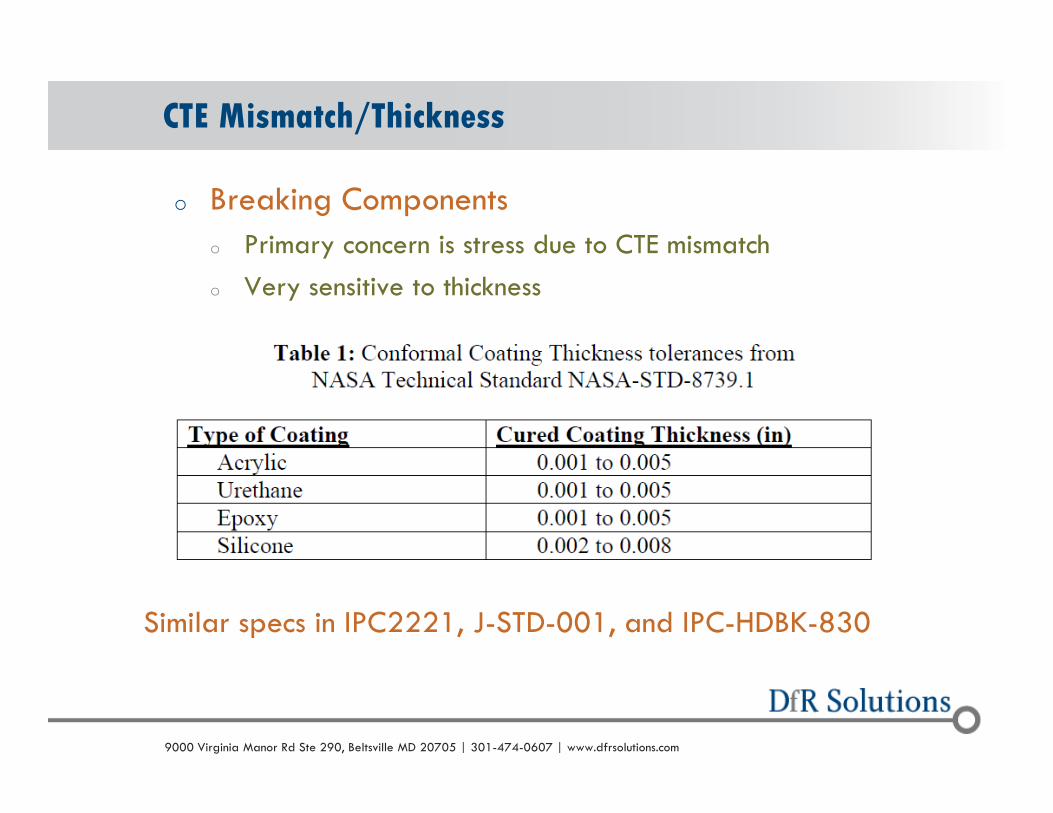
o Breaking Components
o Primary concern is stress due to CTE mismatch
o Very sensitive to thickness
CTE Mismatch/Thickness
Similar specs in IPC2221, J-STD-001, and IPC-HDBK-830

© 2004 - 2007© 2004 - 20109000 Virginia Manor Rd Ste 290, Beltsville MD 20705 | 301-474-0607 | www.dfrsolutions.com
o Problem 1: Does Not Consider Low Standoff Components
o QFN standoff can be less than five mil (125 microns)
o Problem 2: Does Not Consider Glass Transition Temperature (Tg)
Problems
© 2004 - 2007© 2004 - 20109000 Virginia Manor Rd Ste 290, Beltsville MD 20705 | 301-474-0607 | www.dfrsolutions.com11
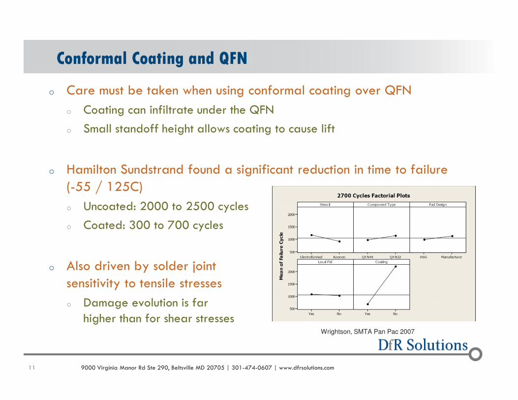
Conformal Coating and QFN
o Care must be taken when using conformal coating over QFN
o Coating can infiltrate under the QFN
o Small standoff height allows coating to cause lift
o Hamilton Sundstrand found a significant reduction in time to failure (-55 / 125C)
o Uncoated: 2000 to 2500 cycles
o Coated: 300 to 700 cycles
o Also driven by solder joint sensitivity to tensile stresses
o Damage evolution is far higher than for shear stresses
Wrightson, SMTA Pan Pac 2007

© 2004 - 2007© 2004 - 20109000 Virginia Manor Rd Ste 290, Beltsville MD 20705 | 301-474-0607 | www.dfrsolutions.com
o Dip coated assembly with BGA technology
o Passed ALT (-40C / 100C)
o Failing quickly in the field
Solder Fracture –Why?

© 2004 - 2007© 2004 - 20109000 Virginia Manor Rd Ste 290, Beltsville MD 20705 | 301-474-0607 | www.dfrsolutions.com
Coating Under Component –Causing Lifting
© 2004 - 2007© 2004 - 20109000 Virginia Manor Rd Ste 290, Beltsville MD 20705 | 301-474-0607 | www.dfrsolutions.com
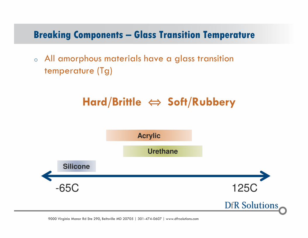
o All amorphous materials have a glass transition temperature (Tg)
Hard/Brittle ⇔⇔⇔⇔ Soft/Rubbery
Breaking Components – Glass Transition Temperature
-65C 125C
Silicone
Urethane
Acrylic

© 2004 - 2007© 2004 - 20109000 Virginia Manor Rd Ste 290, Beltsville MD 20705 | 301-474-0607 | www.dfrsolutions.com
Tg Behavior
o Near the glass transition temperature (Tg), CTE changes more rapidly than moduluso Changes in the CTE in polymers tend to be driven by changes in the free volume
o Changes in modulus tend to be driven by increases in translational / rotational movement of the polymer chains
o Increases in CTE tend to initiate before decreases in modulus because lower levels of energy (temperature) are required to increase free volume compared to increases in movement along the polymer chains
Polymer Science and Technology, Chapter 4: Thermal Transitions in Polymers,
Robert Oboigbaotor Ebewele, CRC Press, 2000
0.01
0.10
1.00
10.00
35 45 55 65 75 85 95 105
Temperature (oC)
Sto
rag
e M
od
ulu
s (
MP
a)
0
20
40
60
80
100
120
140
CT
E (p
pm
/ oC)
Storage Modulus
CTE
High stresses generated due to CTE increase before modulus decrease

© 2004 - 2007© 2004 - 20109000 Virginia Manor Rd Ste 290, Beltsville MD 20705 | 301-474-0607 | www.dfrsolutions.com
o Traditional Conformal Coatings are NOT hermetico Moisture will diffuse through
o Requires good adhesion to the circuit boardo Bubbles/Voids/Delam can drive micro-condensation
o Can make it electrochemical migration MORE likely
Concentrate Contaminants

© 2004 - 2007© 2004 - 20109000 Virginia Manor Rd Ste 290, Beltsville MD 20705 | 301-474-0607 | www.dfrsolutions.com
Sulfur Corrosion Sites on Coated Hybrid
• Silicone coating,
ceramic hybrid
• Used in industrial controls
• Customer reported failures
after 12 to 36 months in the field
• X-ray identified several separations
© 2004 - 2007© 2004 - 20109000 Virginia Manor Rd Ste 290, Beltsville MD 20705 | 301-474-0607 | www.dfrsolutions.com
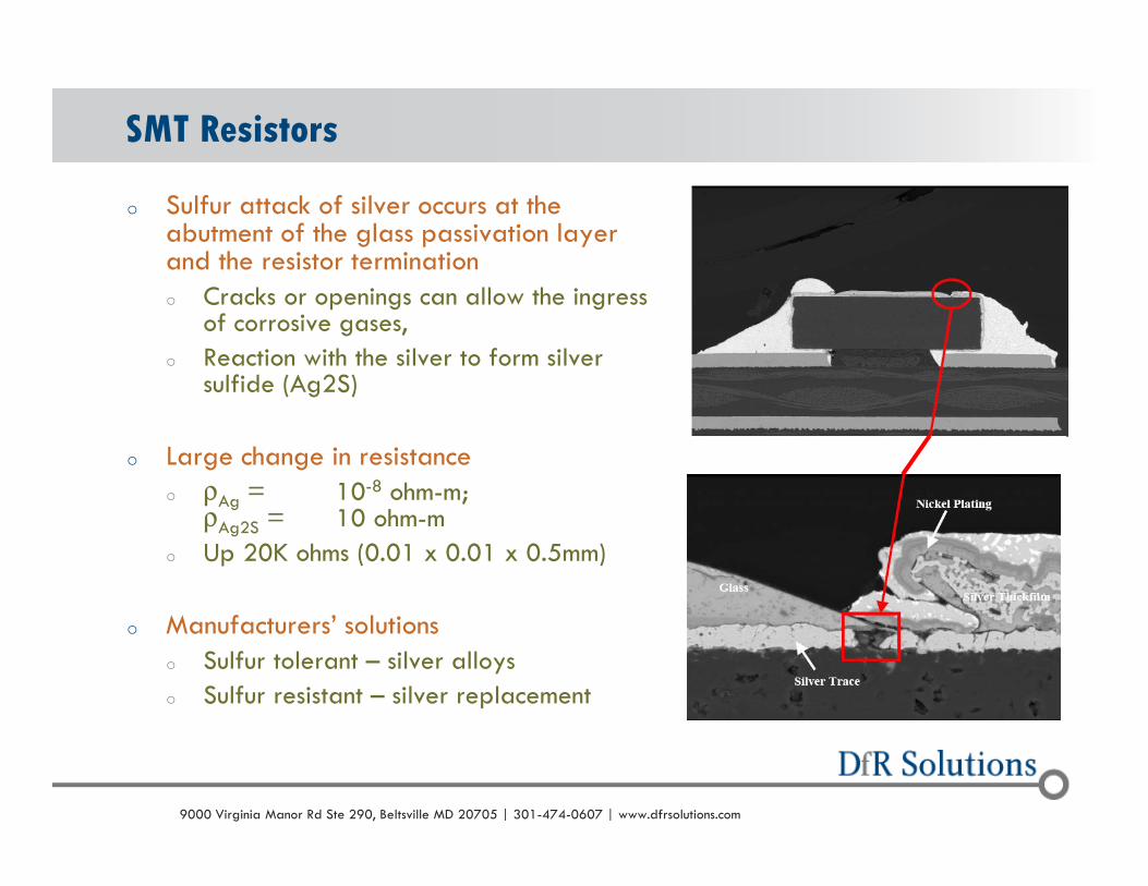
o Sulfur attack of silver occurs at the abutment of the glass passivation layer and the resistor terminationo Cracks or openings can allow the ingress
of corrosive gases,
o Reaction with the silver to form silver sulfide (Ag2S)
o Large change in resistanceo ρAg = 10-8 ohm-m;
ρAg2S = 10 ohm-m
o Up 20K ohms (0.01 x 0.01 x 0.5mm)
o Manufacturers’ solutionso Sulfur tolerant – silver alloys
o Sulfur resistant – silver replacement
SMT Resistors

© 2004 - 2007© 2004 - 20109000 Virginia Manor Rd Ste 290, Beltsville MD 20705 | 301-474-0607 | www.dfrsolutions.com
o Selecting the Correct Cleaning Procedure
o Ensure a high surface cleanliness – aiding adhesion
I Feel the Need for Clean!!!!
Reference: Conformal Coating Issues: When Reliability Goes Astray, Dr. Helmut Schweigart, Zestron Europe.

© 2004 - 2007© 2004 - 20109000 Virginia Manor Rd Ste 290, Beltsville MD 20705 | 301-474-0607 | www.dfrsolutions.com
Conformal Coating and No-Clean
o Concerns about applying conformal coating over no-clean flux residueso Conformal coating suppliers tend to not
recommend
o Some have compatibility docs
o Residues can reduce adhesion, potentially resulting in delaminationo Creates micro-condensation conditions;
more detrimental than no conformal coating
o Has not stopped the practiceo Current industry standards create relatively
benign conditions
o Allows products to pass qualification

© 2004 - 2007© 2004 - 20109000 Virginia Manor Rd Ste 290, Beltsville MD 20705 | 301-474-0607 | www.dfrsolutions.com
Potting Materials
© 2004 - 2007© 2004 - 20109000 Virginia Manor Rd Ste 290, Beltsville MD 20705 | 301-474-0607 | www.dfrsolutions.com
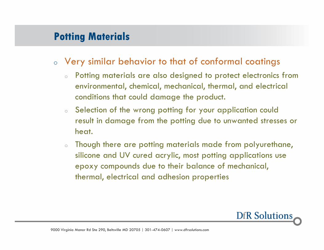
o Very similar behavior to that of conformal coatings
o Potting materials are also designed to protect electronics from environmental, chemical, mechanical, thermal, and electrical conditions that could damage the product.
o Selection of the wrong potting for your application could result in damage from the potting due to unwanted stresses or heat.
o Though there are potting materials made from polyurethane, silicone and UV cured acrylic, most potting applications use epoxy compounds due to their balance of mechanical, thermal, electrical and adhesion properties
Potting Materials
© 2004 - 2007© 2004 - 20109000 Virginia Manor Rd Ste 290, Beltsville MD 20705 | 301-474-0607 | www.dfrsolutions.com
o Questions to ask yourself.
o Does the potting compound perform a thermal function?
o Does it need to protect from aggressive chemicals or moisture?
o Does it need to protect from shock loads?
o Will the potting see high temperatures during manufacturing?
o Are issues such as outgassing, cryogenic operation, or medical compatibility involved?
o Ask the right questions during the design cycle to keep problems to a minimum.
Why Use Potting Materials?

© 2004 - 2007© 2004 - 20109000 Virginia Manor Rd Ste 290, Beltsville MD 20705 | 301-474-0607 | www.dfrsolutions.com
o One of the most common issues with selecting the right potting material is understanding your thermal requirements
o Typically selected based on min and max temperatures
o Maybe OK, but does not take ramp times and dwells into consideration
o Failing to consider dwell and ramp times often can lead to over specifying the materials
o For example, if you select a material with a 200C continuous rating, it would be able to withstand a short burst at 250C during a soldering operation
o Ignoring the short dwell time could result in selecting a much more expensive material than you actually require.
Know Your Thermal Situation

© 2004 - 2007© 2004 - 20109000 Virginia Manor Rd Ste 290, Beltsville MD 20705 | 301-474-0607 | www.dfrsolutions.com
o Typically, manufacturers will select the potting material with the fastest cure cycle.
o A risk is that the fast cure can result in a larger exothermic reaction which could possibly cause damage (potential >200C)
o Fast cures also have the potential for entrapped bubbles, which can impact the materials electrical and mechanical properties
o The selection of a 1 or 2 part material also can have an impact – selecting the easiest approach may not be the best
o The more potting material involved the higher risk associated with the exothermic reaction during curing especially in thicknesses greater than ¼ to ½ inch
The Curing Process

© 2004 - 2007© 2004 - 20109000 Virginia Manor Rd Ste 290, Beltsville MD 20705 | 301-474-0607 | www.dfrsolutions.com
o Shrinkage: Potting materials will shrink, sometimes as much as 2.3% for an unfilled epoxy
o If not accounted for this shrinkage can increase stress levels on electronic components, crate leak paths, and create visual defects
o Good news – shrinkage can be controlled by selecting the right material
o Filled potting and slower curing materials will incur less shrinkage
o Adhesion: Some potting materials have low surface energy and do not bond easily
o Substrate materials can be treated with surface treatments or primers
o Undercuts in the housing can be used to let the cured potting “lock” itself into the housing
Think About Shrinkage/Adhesion
© 2004 - 2007© 2004 - 20109000 Virginia Manor Rd Ste 290, Beltsville MD 20705 | 301-474-0607 | www.dfrsolutions.com
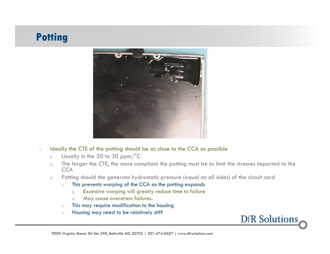
o Ideally the CTE of the potting should be as close to the CCA as possibleo Usually in the 20 to 30 ppm/°Co The larger the CTE, the more compliant the potting must be to limit the stresses imparted to the
CCAo Potting should the generate hydrostatic pressure (equal on all sides) of the circuit card
o This prevents warping of the CCA as the potting expandso Excessive warping will greatly reduce time to failure o May cause overstress failures.
o This may require modification to the housing o Housing may need to be relatively stiff
Potting
© 2004 - 2007© 2004 - 20109000 Virginia Manor Rd Ste 290, Beltsville MD 20705 | 301-474-0607 | www.dfrsolutions.com
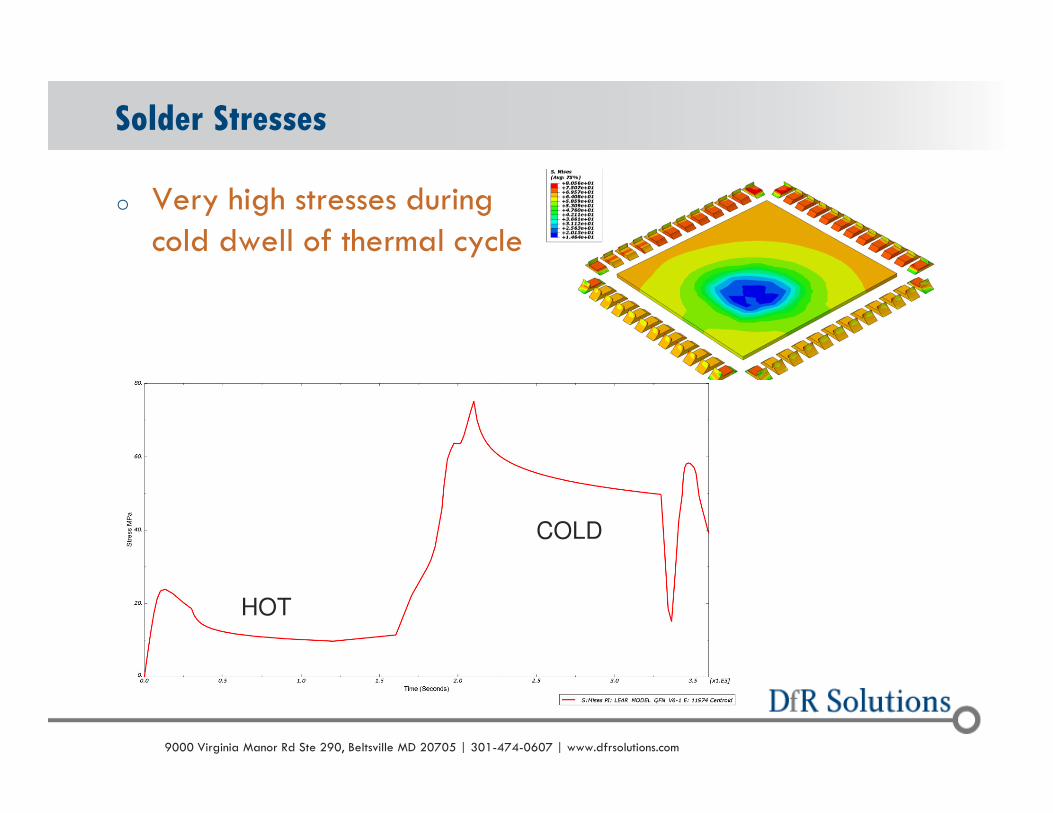
o Very high stresses during cold dwell of thermal cycle
Solder Stresses
HOT
COLD
© 2004 - 2007© 2004 - 20109000 Virginia Manor Rd Ste 290, Beltsville MD 20705 | 301-474-0607 | www.dfrsolutions.com
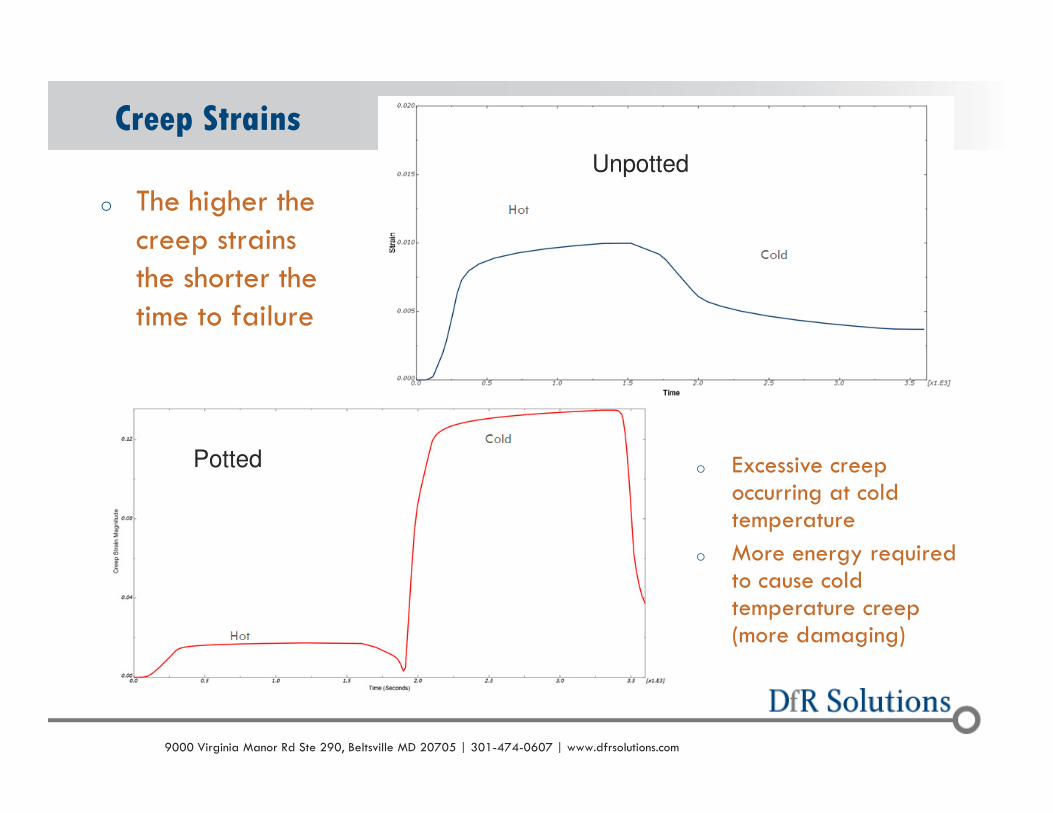
o The higher the creep strains the shorter the time to failure
Creep StrainsUnpotted
Pottedo Excessive creep
occurring at cold temperature
o More energy required to cause cold temperature creep (more damaging)
© 2004 - 2007© 2004 - 20109000 Virginia Manor Rd Ste 290, Beltsville MD 20705 | 301-474-0607 | www.dfrsolutions.com
o Mechanical properties of the potting material
o Glass transition temperature (Tg) – should be specified outside the operational range
o Modulus should be specified above and below the Tg
o CTE should be specified above and below the Tg
o The design of the housing
o May provide a surface to which the potting material can pull against when shrinking causing PCB warpage
o Should be designed to provide as close to a hydrostatic pressure as possible (equal pressure on all sides)
Potting Conclusions
© 2004 - 2007© 2004 - 20109000 Virginia Manor Rd Ste 290, Beltsville MD 20705 | 301-474-0607 | www.dfrsolutions.com
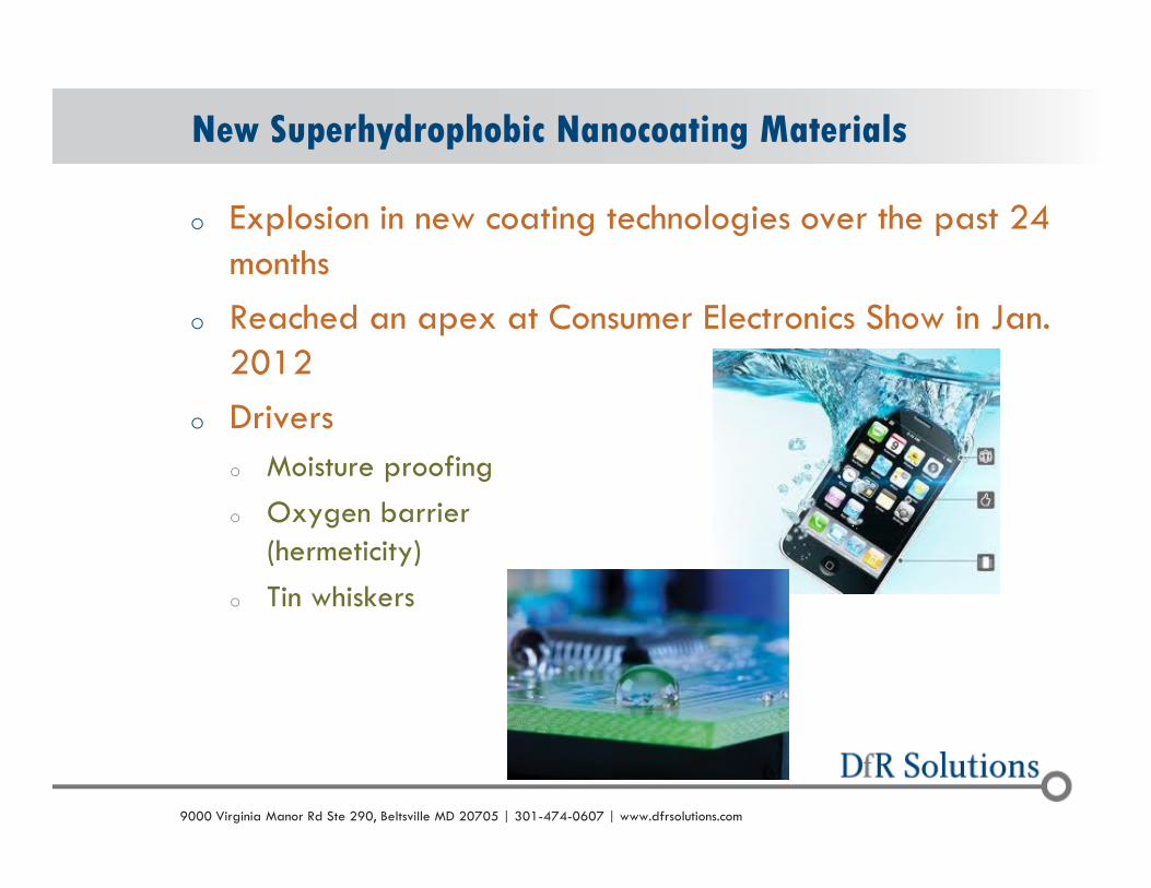
o Explosion in new coating technologies over the past 24 months
o Reached an apex at Consumer Electronics Show in Jan. 2012
o Drivers
o Moisture proofing
o Oxygen barrier(hermeticity)
o Tin whiskers
New Superhydrophobic Nanocoating Materials

© 2004 - 2007© 2004 - 20109000 Virginia Manor Rd Ste 290, Beltsville MD 20705 | 301-474-0607 | www.dfrsolutions.com
o Definition: Wetting angle far greater than the 90 degrees typically defined as hydrophobic
o Can create barriers far more resistant to humidity and condensation than standard conformal coatings
Super Hydrophobicity
© 2004 - 2007© 2004 - 20109000 Virginia Manor Rd Ste 290, Beltsville MD 20705 | 301-474-0607 | www.dfrsolutions.com
o Voltage Breakdowno Levels tend to be lower compared to existing coatings (acrylic, urethane, silicone)o Can be an issue in terms of MIL and IPC specifications
o Optically Transparento Inspection is challenging
o Costo Likely more expensive than common wet coatingso However, major cell phone manufacturer claims significant ROI based on drop in
warranty costs
o Throughputo Batch process. Coating times tend to be 10 to 30 minutes, depending upon desired
thicknesso However, being used in high volume manufacturing
Risks?

© 2004 - 2007© 2004 - 20109000 Virginia Manor Rd Ste 290, Beltsville MD 20705 | 301-474-0607 | www.dfrsolutions.com
o There is significant opportunity for field performance improvement and cost reduction through the use of nanocoatings
o Requires a knowledge of the materials and processes on the marketo Benefits vs. Risks
o With any new technology, do not rely on standard qualification tests!o A physics-based test plan provides the most robust mitigation
Conclusion
© 2004 - 2007© 2004 - 20109000 Virginia Manor Rd Ste 290, Beltsville MD 20705 | 301-474-0607 | www.dfrsolutions.com
THANKSGreg Caswell
301-640-5825 (office)
443-834-9284 (cell)