coal combustion waste impoundment - dam … coal combustion waste impoundment dam assessment report...
TRANSCRIPT


FINAL
Coal Combustion Waste Impoundment
Dam Assessment Report
Site 25
Fly Ash Pond & Bottom Ash Pond American Electric Power
Philip Sporn Generating Plant New Haven, West Virginia
Project # 0-381 Assessment of Dam Safety
Coal Combustion Surface Impoundments For the REAC Program
Prepared for:
Lockheed Martin Services, Inc. Edison, New Jersey
For United States Environmental Protection Agency
Cincinnati, Ohio
Prepared by:
Dewberry & Davis LLC Fairfax, Virginia
Under Contract Number: EP-C-04-032: REAC
October 2009 Revised December 9, 2009

FINAL
Philip Sporn Generating Plant ii American Electric Power Coal Combustion Waste Impoundment
New Haven, West Virginia Dam Assessment Report
INTRODUCTION AND CONCLUSIONS The release of over 5 million cubic yards of coal ash from the Tennessee Valley Authority's Kingston, Tennessee, facility in December 2008 serves as an important reminder of the need for our continued diligence on disposal units where coal combustion wastes are managed. The coal ash from the facility flooded more than 300 acres of land, damaging homes and property. It is critical that we all work to the best of our abilities to prevent a similar catastrophic failure and resultant environmental damage. One of the first steps in this effort is to assess the stability of the impoundments and similar units that contain coal combustion residuals and by-products to determine if and where corrective measures may be needed and then to carry out those measures as expeditiously as possible. This report for the American Electric Power Philip Sporn Generating Plant facility assesses the stability and functionality of the fly ash and bottom ash management units. This evaluation is based on a site assessment conducted on Thursday, September 3rd, 2009 by Dewberry & Davis, Inc professional engineers. On the basis of Dewberry engineers’ review of reference documentation and visual observations, we conclude that the Fly Ash Pond and Bottom Ash Pond should both be classified as FAIR for continued safe operation. This classification reflects three dam assessor concerns and a lack of site specific studies / assessments that address these concerns:
• the use of fly ash as a material of construction and foundation for the existing eastern raised dike at the Fly Ash Pond and the potential for liquefaction,
• ongoing occurrence of ground vibrations that could affect slope stability for both ponds, • slope stability for upper sections of the eastern dike at the Fly Ash Pond,
PURPOSE AND SCOPE This report evaluates the condition of and potential for waste release from two High Hazard Potential management units. To protect lives and property from the consequences of a dam failure or the improper release of impounded slurry at electric utilities, the U.S. Environmental Protection Agency (EPA) has begun investigating the potential for catastrophic failure of Coal Combustion Surface Impoundments (management units). EPA seeks to identify conditions that may destabilize the structure and functionality of a management unit and any appurtenant structures; to note the maintenance status and any deterioration calling for immediate repair; to evaluate conformity with current design and construction practices; and to determine the hazard potential classification for units not currently classified by the management unit owner or by a state or federal agency. The initiative will address management units classified as having a Less-than-Low, Low, Significant or High Hazard Potential ranking. (For Classification, see pp. 3-8 of the 2004 Federal Guidelines for Dam Safety.) The USEPA and its contractors used the following definitions for this study:
"Surface Impoundment or impoundment means a facility or part of a facility which is a natural topographic depression, man-made excavation, or diked area formed primarily of earthen materials (although it may be lined with man-made materials), which is designed to hold an accumulation of liquid wastes or wastes containing free liquids, and which is not an injection well. Examples of surface impoundments are holding, storage, settling, and aeration pits, ponds, and lagoons."

FINAL
Philip Sporn Generating Plant iii American Electric Power Coal Combustion Waste Impoundment
New Haven, West Virginia Dam Assessment Report
For this study, the “earthen materials” could include coal combustion residuals. EPA did not stipulate an exclusion for small units or distinguish whether the placement was temporary or permanent. Furthermore, the study covers not only waste units designated as surface impoundments, but also other units designated as landfills that receive free liquids. EPA is addressing any land-based units that receive fly ash, bottom ash, boiler slag, or flue gas emission control wastes along with free liquids. If the landfill is receiving coal combustion wastes with only enough liquids for proper compaction, then no free liquids should be present; EPA sought no information on such units. In some cases coal combustion wastes are separated from the water, and the water containing de minimus levels of fly ash, bottom ash, slag, or flue gas emission control wastes, goes to an impoundment. EPA is including such impoundments in this study, because chemicals of concern may have leached from the solid coal combustion wastes into the waste waters, leaving suspended solids remaining.
EPA sent two engineers, one of whom was a professional engineer (PE), for a one-day site visit. The team met with the management unit owner and several other supervisors to discuss engineering characteristics and management unit stability. During the site visit, the team collected more information to help determine the hazard potential classifications.
LIMITATIONS
The assessment of dam safety reported herein is based on field observations and review of readily available information provided by the owner/operator of the subject coal combustion waste management unit(s). Qualified Dewberry engineering personnel performed the field observations and review and made the assessment in conformance with the required scope of work and in accordance with reasonable and acceptable engineering practices. No other warranty, either written or implied, is made with regard to our assessment of dam safety.

FINAL
Philip Sporn Generating Plant iv American Electric Power Coal Combustion Waste Impoundment
New Haven, West Virginia Dam Assessment Report
Contents
1.0 CONCLUSIONS AND RECOMMENDATIONS .................................................................................................................................... 1-1
1.1 CONCLUSIONS .......................................................................................................................................................................... 1-1 1.1.1 Conclusions Regarding the Structural Soundness of the Management Unit(s) ................................................... 1-1 1.1.2 Conclusions Regarding the Hydrologic/Hydraulic Safety of the Management Unit(s) ....................................... 1-1 1.1.3 Conclusions Regarding the Adequacy of Supporting Technical Documentation ................................................. 1-2 1.1.4 Conclusions Regarding the Description of the Management Unit(s) .................................................................... 1-2 1.1.5 Conclusions Regarding the Field Observations ....................................................................................................... 1-2 1.1.6 Conclusions Regarding the Adequacy of Maintenance and Methods of Operation ............................................. 1-2 1.1.7 Conclusions Regarding the Adequacy of the Surveillance and Monitoring Program ......................................... 1-2 1.1.8 Classification Regarding Suitability for Continued Safe and Reliable Operation ................................................ 1-3
1.2 RECOMMENDATIONS................................................................................................................................................................ 1-3 1.2.1 Recommendations Regarding the Structural Stability .......................................................................................... 1-3 1.2.2 Recommendations Regarding the Hydrologic/Hydraulic Safety .......................................................................... 1-3 1.2.3 Recommendations Regarding the Supporting Technical Documentation ............................................................ 1-3 1.2.4 Recommendations Regarding the Description of the Management Unit(s)......................................................... 1-4 1.2.5 Recommendations Regarding the Field Observations ............................................................................................ 1-4 1.2.6 Recommendations Regarding the Maintenance and Methods of Operation ........................................................ 1-4 1.2.7 Recommendations Regarding the Surveillance and Monitoring Program ........................................................... 1-4 1.2.8 Recommendations Regarding Continued Safe and Reliable Operation ................................................................ 1-4
2.0 DESCRIPTION OF THE COAL COMBUSTION WASTE MANAGEMENT UNIT(S) ............................................................................... 2-1
2.1 LOCATION ................................................................................................................................................................................. 2-1 2.2 SIZE AND HAZARD CLASSIFICATION ...................................................................................................................................... 2-2 2.3 AMOUNT AND TYPE OF RESIDUALS CURRENTLY CONTAINED IN THE UNIT(S) AND MAXIMUM CAPACITY ........................... 2-4 2.4 PRINCIPAL PROJECT STRUCTURES ....................................................................................................................................... 2-4
2.4.1 Earth Embankment Dam ............................................................................................................................................ 2-4 2.4.2 Outlet Structures ..................................................................................................................................................... 2-24
2.5 CRITICAL INFRASTRUCTURE WITHIN FIVE MILES DOWN GRADIENT.................................................................................... 2-25
3.0 SUMMARY OF RELEVANT REPORTS, PERMITS AND INCIDENTS .................................................................................................. 3-1
3.1 SUMMARY OF REPORTS ON THE SAFETY OF THE MANAGEMENT UNIT(S) .............................................................................. 3-1 3.2 SUMMARY OF LOCAL, STATE AND FEDERAL ENVIRONMENTAL PERMITS .............................................................................. 3-3 3.3 SUMMARY OF SPILL/RELEASE INCIDENTS (IF ANY) ............................................................................................................. 3-3
4.0 SUMMARY OF HISTORY OF CONSTRUCTION AND OPERATION ................................................................................................... 4-1
4.1 SUMMARY OF CONSTRUCTION HISTORY ................................................................................................................................ 4-1 4.1.1 Original Construction ................................................................................................................................................. 4-1 4.1.2 Significant Changes/Modifications in Design since Original Construction ........................................................ 4-2 4.1.3 Significant Repairs/Rehabilitation since Original Construction ......................................................................... 4-10

FINAL
Philip Sporn Generating Plant v American Electric Power Coal Combustion Waste Impoundment
New Haven, West Virginia Dam Assessment Report
4.2 SUMMARY OF OPERATIONAL HISTORY .................................................................................................................................. 4-11 4.2.1 Original Operational Procedures ............................................................................................................................. 4-11 4.2.2 Significant Changes in Operational Procedures since Original Startup ............................................................. 4-11 4.2.3 Current Operational Procedures ............................................................................................................................ 4-12 4.2.4 Other Notable Events since Original Startup ....................................................................................................... 4-13
5.0 FIELD OBSERVATIONS ................................................................................................................................................................... 5-1
5.1 PROJECT OVERVIEW AND ASSESSMENT................................................................................................................................. 5-1 5.2 EARTH EMBANKMENT DAM ...................................................................................................................................................... 5-1
5.2.1 II Crest ......................................................................................................................................................................... 5-1 5.2.2 Upstream Slope........................................................................................................................................................... 5-1 5.2.3 Downstream Slope and Toe ...................................................................................................................................... 5-3 5.2.4 Abutments and Groin Areas ...................................................................................................................................... 5-9
5.3 OUTLET STRUCTURES ............................................................................................................................................................. 5-9 5.3.1 Overflow Structure .................................................................................................................................................... 5-9 5.3.2 Outlet Conduit ............................................................................................................................................................. 5-9 5.3.3 Emergency Spillway (If Present) ............................................................................................................................. 5-9 5.3.4 Low Level Outlet ......................................................................................................................................................... 5-9
6.0 HYDROLOGIC/HYDRAULIC SAFETY .............................................................................................................................................. 6-1
6.1 SUPPORTING TECHNICAL DOCUMENTATION .......................................................................................................................... 6-1 6.1.1 Floods of Record ......................................................................................................................................................... 6-1 6.1.2 Inflow Design Flood ..................................................................................................................................................... 6-1 6.1.3 Spillway Rating ........................................................................................................................................................... 6-2 6.1.4 Downstream Flood Analysis ...................................................................................................................................... 6-2
6.2 ADEQUACY OF SUPPORTING TECHNICAL DOCUMENTATION ................................................................................................. 6-4 6.3 ASSESSMENT OF HYDROLOGIC/HYDRAULIC SAFETY ........................................................................................................... 6-4
7.0 STRUCTURAL STABILITY ................................................................................................................................................................7-1
7.1 SUPPORTING TECHNICAL DOCUMENTATION ...........................................................................................................................7-1 7.1.1 Stability Analyses and Load Cases Analyzed ............................................................................................................7-1 7.1.2 Design Properties and Parameters of Materials .....................................................................................................7-1 7.1.3 Uplift and/or Phreatic Surface Assumptions ....................................................................................................... 7-13 7.1.4 Factors of Safety and Base Stresses..................................................................................................................... 7-16 7.1.5 Liquefaction Potential ............................................................................................................................................... 7-19 7.1.6 Critical Geological Conditions and Seismicity ....................................................................................................... 7-21
7.2 ADEQUACY OF SUPPORTING TECHNICAL DOCUMENTATION ............................................................................................... 7-23 7.3 ASSESSMENT OF STRUCTURAL STABILITY .......................................................................................................................... 7-23
8.0 MAINTENANCE AND METHODS OF OPERATION ............................................................................................................................ 8-1
8.1 OPERATIONAL PROCEDURES .................................................................................................................................................. 8-1 8.2 MAINTENANCE OF THE DAM AND PROJECT FACILITIES .......................................................................................................... 8-1

FINAL
Philip Sporn Generating Plant vi American Electric Power Coal Combustion Waste Impoundment
New Haven, West Virginia Dam Assessment Report
8.3 ASSESSMENT OF MAINTENANCE AND METHODS OF OPERATION .......................................................................................... 8-2 8.3.1 Adequacy of Operational Procedures ..................................................................................................................... 8-2 8.3.2 Adequacy of Maintenance ......................................................................................................................................... 8-2
9.0 SURVEILLANCE AND MONITORING PROGRAM ............................................................................................................................. 9-1
9.1 SURVEILLANCE PROCEDURES................................................................................................................................................. 9-1 9.2 INSTRUMENTATION MONITORING ........................................................................................................................................... 9-1
9.2.1 Instrumentation Plan .................................................................................................................................................. 9-1 9.2.2 Instrumentation Monitoring Results ........................................................................................................................ 9-2 9.2.3 Evaluation .................................................................................................................................................................... 9-2
9.3 ASSESSMENT OF SURVEILLANCE AND MONITORING PROGRAM ........................................................................................... 9-2 9.3.1 Adequacy of Inspection Program ............................................................................................................................. 9-2 9.3.2 Adequacy of Instrumentation Monitoring Program ............................................................................................... 9-2

FINAL
Philip Sporn Generating Plant vii American Electric Power Coal Combustion Waste Impoundment
New Haven, West Virginia Dam Assessment Report
APPENDICES APPENDIX A – REFERENCE DOCUMENTS Doc 1: 2008 Sporn DIMP Inspection Report.pdf Doc 2: 2009 Inspection Report.pdf Doc 3: AEPSC Civil Engineering – Bottom Ash Pond – Engineering Repo.pdf Doc 4: Casagrande Consultants – September, 1982 – Report to AEPSC O.pdf Doc 5: File Folder 1 - Aerial Mapping From 2007 - Plotted at 1.pdf=.pdf Doc 6: File Folder 1 - Well and Piezometer Location Plan with Coord.pdf Doc 7: File Folder 2 - Stantec - August 2009 - Scour Analysis Repor.pdf Doc 8: File Folder 3 - Response to Item 3 of Order Related to Minin.pdf Doc 9: File Folder 3 - Well and Piezometer Location Plan with Corrd.pdf Doc 10: File Folder 4 - WVDEP DWWM Dam Safety Section Inspection Rep.pdf Doc 11: File Folder 6 - Monitoring and Emergency Action Plan.pdf Doc 12: File Folder 12 - Deformation Survey.pdf Doc 13: File Folder - 9 WVDEP DWWM Dam Safety Section 2002 Certifica.pdf Doc 14: Fly ash complex-North Dam Modification ShawStoneWebster Marc.pdf Doc 15: Fly ash dam Stability Analysis AEP March 2009.pdf Doc 16: Geotechnical Data Collection Report Terracon March 2009.pdf Doc 17: Monthly-Quarterly Sporn Fly Ash Pond Dike Inspection Checkli.pdf Doc 18: Phillip Sporn Plant Drawings 1.pdf Doc 19: Phillip Sporn Plant Drawings 2.pdf Doc 20: Project E040563.10.pdf Doc 21: Response to Item 2 of Order Related to Stability - AEPSC Civ.pdf Doc 22: RE-Sporn Unit 5 Dam.pdf Doc 23: Sporn FA & BA Pond Modifications.pdf Doc 24: Sporn Fly Ash Pond Well and Piezometer Reading.pdf Doc 25: Woodward-Clyde Consultants - November, 1978 - Report to AEPS.pdf APPENDIX B – SITE ASSESSMENT DOCUMENTATION Doc 1: Coal Combustion Dam Inspection Checklist Form – Philip Sporn Fly Ash Pond Doc 2: Coal Combustion Dam Inspection Checklist Form – Philip Sporn Bottom Ash Pond Doc 3: Site Visit Photographs, 9/3/09

FINAL
Philip Sporn Generating Plant viii American Electric Power Coal Combustion Waste Impoundment
New Haven, West Virginia Dam Assessment Report
APPENDIX C – CORRESPONDENCE & ADDITIONAL REFERENCE DOCUMENTATION Doc 1: Dewberry’s Memo to EPA Philip Sporn Management Unit – Potential for Immediate Failure (10/28/09) Doc 2: AEP Response to Draft EPA RecommendationsR1 - Sporn.doc (11/2/09) Doc 3: Attachment A SP Liquefaction Study.pdf Doc 4: Liquefaction Attachment A1.pdf Doc 5: Liquefaction Attachment A2.pdf Doc 6: Liquefaction Attachment A3.pdf Doc 7: Liquefaction Attachment A4.pdf Doc 8: Embankment Sloughing Repairs Attachment BMaster.pdf Doc 9: Slope Stability Attachment CMaster.pdf Doc 10: Sporn and Kingston Similarities Attachment DMaster.pdf Doc 11: Supplemental Information to Address Liquefaction Analysis.doc (11/6/09) Doc 12: Sporn attachment #1.pdf Doc 13: Sporn attachment #2.pdf Doc 14: Sporn attachment #3.pdf Doc 15: Dewberry Evaluation of AEP Response.pdf (11/10/09) Doc 16: AEP Company Comments.pdf (11/23/09)
FINAL
Philip Sporn Generating Plant 1-1 American Electric Power Coal Combustion Waste Impoundment
New Haven, West Virginia Dam Assessment Report
1.0 CONCLUSIONS AND RECOMMENDATIONS
1.1 CONCLUSIONS
Conclusions are based on visual observations from the one-day site visit, review of technical documentation provided by American Electric Power, and review of state inspection reports.
1.1.1 Conclusions Regarding the Structural Soundness of the Management Unit(s)
Fly Ash Pond – The structural stability of the Fly Ash Pond embankments is limited based on the following parameters:
• Surface sloughing has occurred along a majority of the grassed portions of the downstream slope of the western dike;
• There are indications of surface irregularities consistent with past sloughing along the downstream slope of the eastern dike;
• Ground vibrations were felt during the site inspection from railroad operations adjacent to the facility;
• Sections of modified embankments are constructed over, and/or composed of, fly ash material strata which may be susceptible to liquefaction under certain conditions; and
• A lower seismic ground acceleration value than is shown on U.S. National Seismic Hazard Maps was used for slope stability analysis, and upper sections of the eastern dike were not evaluated for slope stability during seismic loading conditions.
Bottom Ash Pond – The structural stability of the Bottom Ash Pond embankments is limited based on the following parameters:
• There are indications of surface irregularities consistent with past sloughing along the downstream slope of the eastern dike;
• Erosion, most likely caused by storm water runoff from the road system along the crest, was observed along the upstream slope of the northwest dike and is beginning to undermine the paved road;
• Isolated areas on the downstream slope of the upper eastern dike have surface irregularities consistent with past surface sloughing;
• Ground vibrations were felt during the site inspection from the railroad operations adjacent to the facility; and
• A lower seismic ground acceleration value than is shown on U.S. National Seismic Hazard Maps was used for slope stability analysis.
1.1.2 Conclusions Regarding the Hydrologic/Hydraulic Safety of the Management Unit(s)

FINAL
Philip Sporn Generating Plant 1-2 American Electric Power Coal Combustion Waste Impoundment
New Haven, West Virginia Dam Assessment Report
Fly Ash Pond – Adequate capacity and freeboard exist to safely pass the design storm. Bottom Ash Pond – Adequate capacity and freeboard exist to safely pass the design storm. 1.1.3 Conclusions Regarding the Adequacy of Supporting Technical Documentation Fly Ash Pond – Railway-induced ground vibration assessments need to be documented. The potential for
liquefaction of the foundation soils, specifically along the eastern dike, need to be better documented. Additionally, a stability analysis on the upper sections of the eastern dike was conducted using earthquake loading conditions that are less stringent than values currently recommended by the U.S. National Seismic Hazard maps.
Bottom Ash Pond – Railway-induced ground vibration assessments need to be documented. 1.1.4 Conclusions Regarding the Description of the Management Unit(s) Fly Ash Pond – Descriptions provided are appropriate. Bottom Ash Pond – Descriptions provided are appropriate.
1.1.5 Conclusions Regarding the Field Observations Fly Ash Pond – Evidence of sloughing was observed along the eastern and western embankments. Railway-
induced ground vibration was also felt during the field assessment. Bottom Ash Pond - Evidence of sloughing was observed along the eastern embankment and erosion was
observed along the northwestern embankment. Railway-induced ground vibration was also felt during the field assessment.
1.1.6 Conclusions Regarding the Adequacy of Maintenance and Methods of Operation Fly Ash Pond – Maintenance and methods of operation are adequate. Bottom Ash Pond – Maintenance and methods of operation are adequate. 1.1.7 Conclusions Regarding the Adequacy of the Surveillance and Monitoring Program Fly Ash Pond – Existing surveillance and monitoring programs are adequate; however, seepage through
embankments needs to be monitored. Bottom Ash Pond – Existing surveillance and monitoring programs are adequate; however, seepage
through embankments needs to be monitored.

FINAL
Philip Sporn Generating Plant 1-3 American Electric Power Coal Combustion Waste Impoundment
New Haven, West Virginia Dam Assessment Report
1.1.8 Classification Regarding Suitability for Continued Safe and Reliable Operation
Fly Ash Pond – Facility is FAIR for continued safe and reliable operation. A classification of “fair” is
appropriate when acceptable performance is expected under all required loading conditions (static, hydrologic, seismic) in accordance with the applicable safety regulatory criteria. Minor deficiencies may exist that require remedial action and/or secondary studies or investigations.
Bottom Ash Pond – Facility is FAIR for continued safe and reliable operation. A classification of “fair”
is appropriate when acceptable performance is expected under all required loading conditions (static, hydrologic, seismic) in accordance with the applicable safety regulatory criteria. Minor deficiencies may exist that require remedial action and/or secondary studies or investigations.
1.2 RECOMMENDATIONS
1.2.1 Recommendations Regarding the Structural Stability Fly Ash Pond –
• Continue with proposed action plan to address sloughing along downstream slopes. AEP Proposed Action Plan is provided in Appendix C (Doc: Embankment Sloughing Repairs Attachment BMaster.pdf)
• Perform an assessment of the effect of railway-induced ground vibrations on embankments.
• Perform slope stability analyses under proper earthquake loading conditions for the upper sections of the eastern dike.
• Perform a site-specific study of the potential for liquefaction of foundation soils.
Bottom Ash Pond –
• Perform remediation along downstream slopes to address sloughing as well as the upstream slopes where erosion is occurring.
• Perform an assessment of the effect of railway-induced ground vibrations on embankments. 1.2.2 Recommendations Regarding the Hydrologic/Hydraulic Safety Fly Ash Pond – None appear warranted at this time.
Bottom Ash Pond – None appear warranted at this time.
1.2.3 Recommendations Regarding the Supporting Technical Documentation Fly Ash Pond – Additional documentation is recommended to address ground vibrations and potential
liquefaction, per Section 1.2.1 Recommendations Regarding the Structural Stability.

FINAL
Philip Sporn Generating Plant 1-4 American Electric Power Coal Combustion Waste Impoundment
New Haven, West Virginia Dam Assessment Report
Bottom Ash Pond – Additional documentation is recommended to address ground vibrations, per Section 1.2.1 Recommendations Regarding the Structural Stability.
1.2.4 Recommendations Regarding the Description of the Management Unit(s) Fly Ash Pond – None appear warranted at this time. Bottom Ash Pond – None appear warranted at this time. 1.2.5 Recommendations Regarding the Field Observations Fly Ash Pond – None appear warranted at this time. Bottom Ash Pond – None appear warranted at this time. 1.2.6 Recommendations Regarding the Maintenance and Methods of Operation Fly Ash Pond – None appear warranted at this time. Bottom Ash Pond – None appear warranted at this time. 1.2.7 Recommendations Regarding the Surveillance and Monitoring Program Fly Ash Pond – Continue current program. Begin monitoring downstream toe of embankments for seepage
quantity and quality as part of the monthly routine inspection. Bottom Ash Pond – Continue current program. Begin monitoring downstream toe of embankments for
seepage quantity and quality as part of the monthly routine inspection. 1.2.8 Recommendations Regarding Continued Safe and Reliable Operation Fly Ash Pond -
• Perform assessment of the effect of railway-induced ground vibration on embankments.
• Perform slope stability analyses with proper seismic loading conditions for upper sections of the eastern dike.
• Perform analyses to determine the potential of soil liquefaction.
• Continue with proposed action plan to address sloughing along the downstream slopes. AEP Proposed Action Plan is provided in Appendix C (Doc: Embankment Sloughing Repairs Attachment BMaster.pdf)
• Begin monitoring downstream toe of embankments for seepage.

FINAL
Philip Sporn Generating Plant 1-5 American Electric Power Coal Combustion Waste Impoundment
New Haven, West Virginia Dam Assessment Report
Bottom Ash Pond -
• Perform assessment of the effect of railway-induced ground vibration on embankments.
• Perform remediation along downstream slopes to address sloughing.
• Perform remediation along the upstream slopes where erosion is occurring.
• Begin monitoring downstream toe of embankments for seepage.
l
FINAL
Philip Sporn Generating Plant 2-1 American Electric Power Coal Combustion Waste Impoundment
New Haven, West Virginia Dam Assessment Report
2.0 DESCRIPTION OF THE COAL COMBUSTION WASTE MANAGEMENT UNIT(S)
2.1 LOCATION
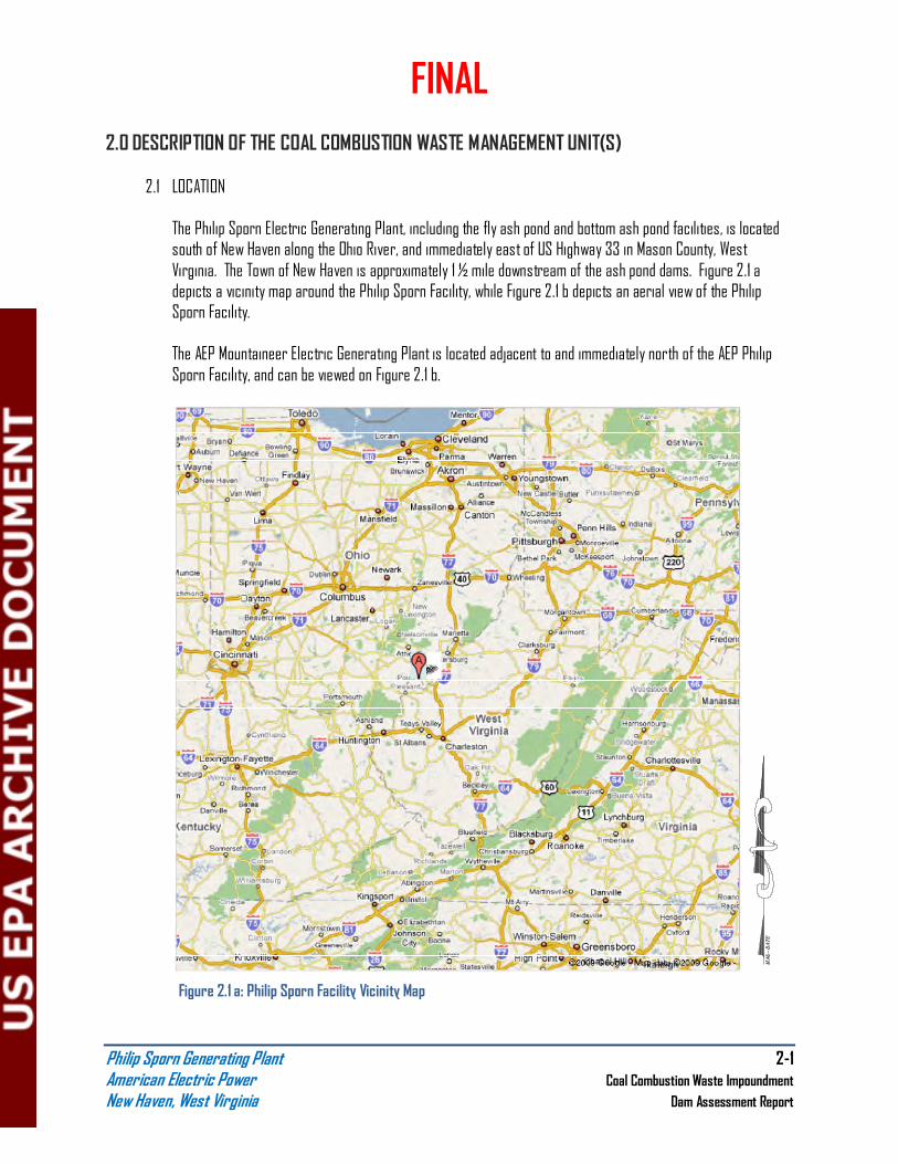
The Philip Sporn Electric Generating Plant, including the fly ash pond and bottom ash pond facilities, is located south of New Haven along the Ohio River, and immediately east of US Highway 33 in Mason County, West Virginia. The Town of New Haven is approximately 1 ½ mile downstream of the ash pond dams. Figure 2.1 a depicts a vicinity map around the Philip Sporn Facility, while Figure 2.1 b depicts an aerial view of the Philip Sporn Facility.
The AEP Mountaineer Electric Generating Plant is located adjacent to and immediately north of the AEP Philip Sporn Facility, and can be viewed on Figure 2.1 b.
Figure 2.1 a: Philip Sporn Facility Vicinity Map

FINAL
Philip Sporn Generating Plant 2-2 American Electric Power Coal Combustion Waste Impoundment
New Haven, West Virginia Dam Assessment Report
Figure 2.1 b: Philip Sporn Facility Aerial View
2.2 SIZE AND HAZARD CLASSIFICATION
The fly ash pond is impounded by an earthen embankment system consisting of a four-sided dike with two internal dikes creating a four cell complex. Based on data provided by American Electric Power, Inc. (AEP), the fly ash pond embankment system was constructed to a maximum height of 65 feet with a crest width of 25 feet, side slopes of 2(H):1(V) to 1.5(H):1(V) and a length of 7,293 feet. The maximum storage volume corresponding to the top of the embankment is 2,219 acre-feet. The classification for size, based on the height of the dam and storage capacity, is Intermediate in accordance with the USACE Recommended Guidelines for Safety Inspection of Dams ER 1110-2-106 criteria (see Table 2.2a for size classification criteria).
Table 2.2a USACE ER 1110-2-106
Size Classification
Category
Impoundment
Storage (Ac-ft) Height (ft)
Small < 1,000 < 40
Intermediate 1,000 to < 50,000 40 to < 100 Large > 50,000 > 100
Bottom Ash Pond
Fly Ash Pond
Ohio River
FINAL
Philip Sporn Generating Plant 2-3 American Electric Power Coal Combustion Waste Impoundment
New Haven, West Virginia Dam Assessment Report
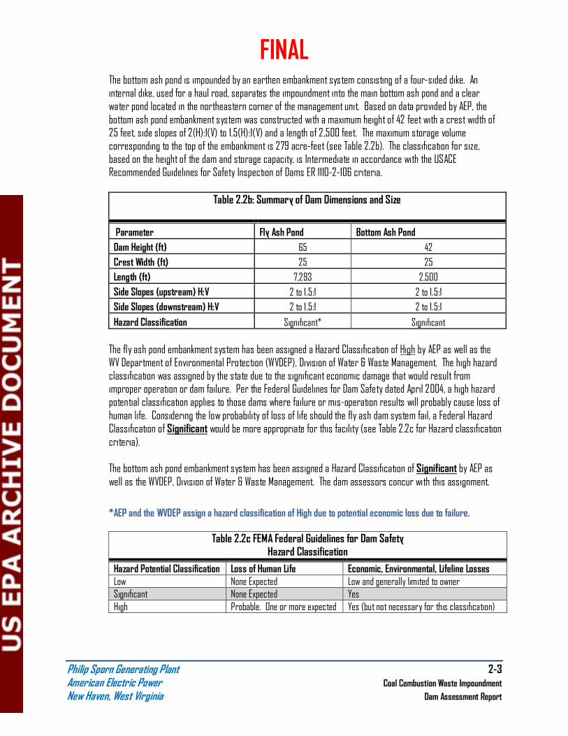
The bottom ash pond is impounded by an earthen embankment system consisting of a four-sided dike. An internal dike, used for a haul road, separates the impoundment into the main bottom ash pond and a clear water pond located in the northeastern corner of the management unit. Based on data provided by AEP, the bottom ash pond embankment system was constructed with a maximum height of 42 feet with a crest width of 25 feet, side slopes of 2(H):1(V) to 1.5(H):1(V) and a length of 2,500 feet. The maximum storage volume corresponding to the top of the embankment is 279 acre-feet (see Table 2.2b). The classification for size, based on the height of the dam and storage capacity, is Intermediate in accordance with the USACE Recommended Guidelines for Safety Inspection of Dams ER 1110-2-106 criteria.
Table 2.2b: Summary of Dam Dimensions and Size
Parameter Fly Ash Pond Bottom Ash Pond
Dam Height (ft) 65 42
Crest Width (ft) 25 25
Length (ft) 7,293 2,500
Side Slopes (upstream) H:V 2 to 1.5:1 2 to 1.5:1
Side Slopes (downstream) H:V 2 to 1.5:1 2 to 1.5:1
Hazard Classification Significant* Significant
The fly ash pond embankment system has been assigned a Hazard Classification of High by AEP as well as the WV Department of Environmental Protection (WVDEP), Division of Water & Waste Management. The high hazard classification was assigned by the state due to the significant economic damage that would result from improper operation or dam failure. Per the Federal Guidelines for Dam Safety dated April 2004, a high hazard potential classification applies to those dams where failure or mis-operation results will probably cause loss of human life. Considering the low probability of loss of life should the fly ash dam system fail, a Federal Hazard Classification of Significant would be more appropriate for this facility (see Table 2.2c for Hazard classification criteria).
The bottom ash pond embankment system has been assigned a Hazard Classification of Significant by AEP as well as the WVDEP, Division of Water & Waste Management. The dam assessors concur with this assignment.
*AEP and the WVDEP assign a hazard classification of High due to potential economic loss due to failure.
Table 2.2c FEMA Federal Guidelines for Dam Safety Hazard Classification
Hazard Potential Classification Loss of Human Life Economic, Environmental, Lifeline Losses
Low None Expected Low and generally limited to owner Significant None Expected Yes
High Probable. One or more expected Yes (but not necessary for this classification)
FINAL
Philip Sporn Generating Plant 2-4 American Electric Power Coal Combustion Waste Impoundment
New Haven, West Virginia Dam Assessment Report
2.3 AMOUNT AND TYPE OF RESIDUALS CURRENTLY CONTAINED IN THE UNIT(S) AND MAXIMUM CAPACITY
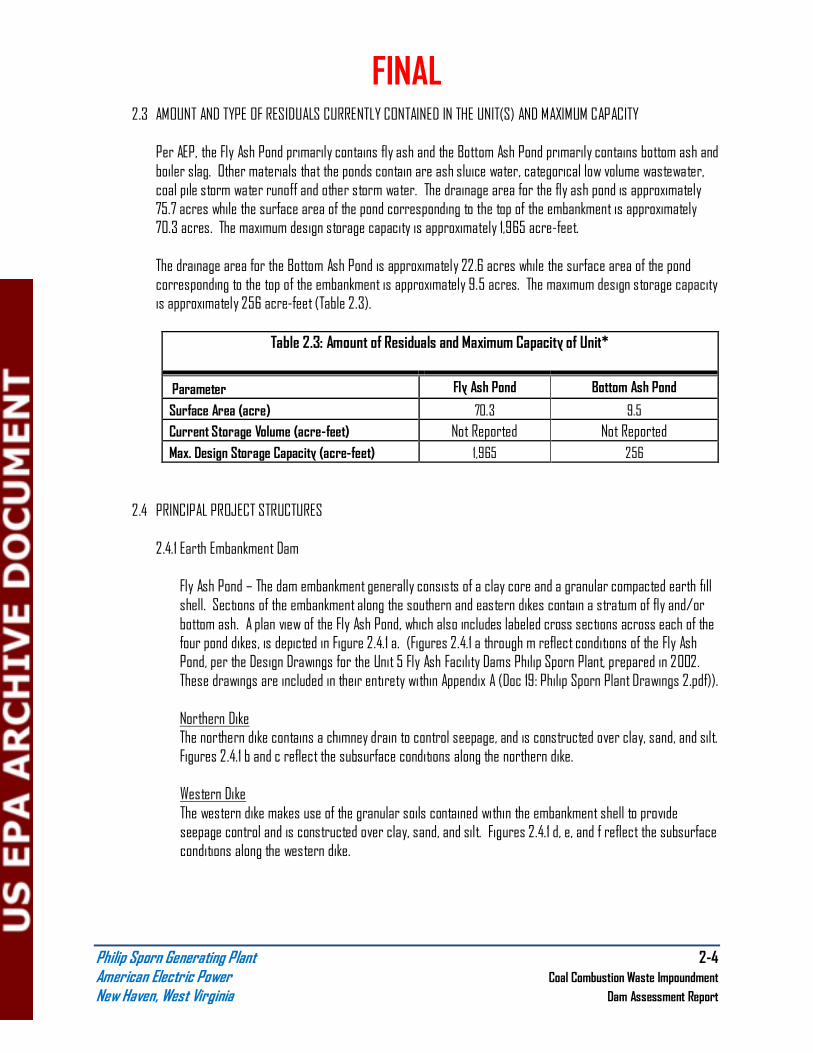
Per AEP, the Fly Ash Pond primarily contains fly ash and the Bottom Ash Pond primarily contains bottom ash and boiler slag. Other materials that the ponds contain are ash sluice water, categorical low volume wastewater, coal pile storm water runoff and other storm water. The drainage area for the fly ash pond is approximately 75.7 acres while the surface area of the pond corresponding to the top of the embankment is approximately 70.3 acres. The maximum design storage capacity is approximately 1,965 acre-feet. The drainage area for the Bottom Ash Pond is approximately 22.6 acres while the surface area of the pond corresponding to the top of the embankment is approximately 9.5 acres. The maximum design storage capacity is approximately 256 acre-feet (Table 2.3).
Table 2.3: Amount of Residuals and Maximum Capacity of Unit*
Parameter Fly Ash Pond Bottom Ash Pond
Surface Area (acre) 70.3 9.5
Current Storage Volume (acre-feet) Not Reported Not Reported
Max. Design Storage Capacity (acre-feet) 1,965 256
2.4 PRINCIPAL PROJECT STRUCTURES
2.4.1 Earth Embankment Dam
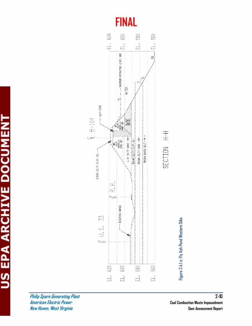
Fly Ash Pond – The dam embankment generally consists of a clay core and a granular compacted earth fill shell. Sections of the embankment along the southern and eastern dikes contain a stratum of fly and/or bottom ash. A plan view of the Fly Ash Pond, which also includes labeled cross sections across each of the four pond dikes, is depicted in Figure 2.4.1 a. (Figures 2.4.1 a through m reflect conditions of the Fly Ash Pond, per the Design Drawings for the Unit 5 Fly Ash Facility Dams Philip Sporn Plant, prepared in 2002. These drawings are included in their entirety within Appendix A (Doc 19: Philip Sporn Plant Drawings 2.pdf)). Northern Dike The northern dike contains a chimney drain to control seepage, and is constructed over clay, sand, and silt. Figures 2.4.1 b and c reflect the subsurface conditions along the northern dike. Western Dike The western dike makes use of the granular soils contained within the embankment shell to provide seepage control and is constructed over clay, sand, and silt. Figures 2.4.1 d, e, and f reflect the subsurface conditions along the western dike.

FINAL
Philip Sporn Generating Plant 2-5 American Electric Power Coal Combustion Waste Impoundment
New Haven, West Virginia Dam Assessment Report
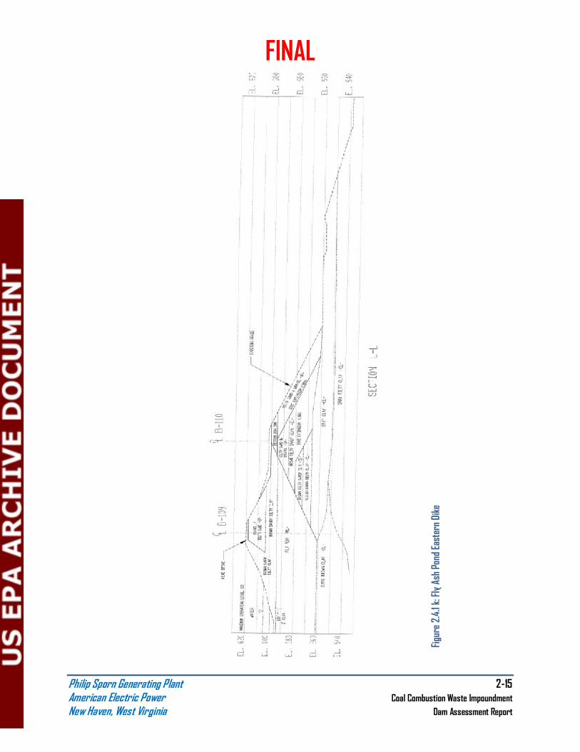
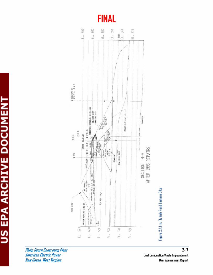
Southern Dike The southern dike makes use of the granular soils contained within the embankment shell to provide seepage control. The dike is constructed over clay and sand, with sections placed over a 31 foot deep stratum of fly ash (resulting from various embankment modifications). Figures 2.4.1 g and h reflect the subsurface conditions along the southern dike. Eastern Dike The eastern dike section makes use of a blanket drain as well as the granular soils contained within the embankment shell to provide seepage control. The dike is constructed over strata of clay, sand and gravel, and sandstone. The embankment dike contains portions placed over a 32.5 to 37.5 foot stratum of fly ash, 5 to 7 feet of bottom ash, and 2 feet of bottom ash on top of 9 feet of fly ash (resulting from various embankment modifications). Figures 2.4.1 j, k, l, and m reflect the subsurface conditions along the eastern dike. See Appendix A (Doc 19: Philip Sporn Plant Drawings 2.pdf) for full size drawings of these subsurface conditions.

FINAL
Philip Sporn Generating Plant 2-6 American Electric Power Coal Combustion Waste Impoundment
New Haven, West Virginia Dam Assessment Report
Figure 2.4.1 a: Fly Ash Pond Plan View

FINAL
Philip Sporn Generating Plant 2-7 American Electric Power Coal Combustion Waste Impoundment
New Haven, West Virginia Dam Assessment Report
Figure 2.4.1 b: Fly Ash Pond Northern Dike

FINAL
Philip Sporn Generating Plant 2-8 American Electric Power Coal Combustion Waste Impoundment
New Haven, West Virginia Dam Assessment Report
Figure 2.4.1 c: Fly Ash Pond Northern Dike

FINAL
Philip Sporn Generating Plant 2-9 American Electric Power Coal Combustion Waste Impoundment
New Haven, West Virginia Dam Assessment Report
Figure 2.4.1 d: Fly Ash Pond Western Dike
FINAL
Philip Sporn Generating Plant 2-10 American Electric Power Coal Combustion Waste Impoundment
New Haven, West Virginia Dam Assessment Report
Figure 2.4.1 e: Fly Ash Pond Western Dike

FINAL
Philip Sporn Generating Plant 2-11 American Electric Power Coal Combustion Waste Impoundment
New Haven, West Virginia Dam Assessment Report
Figure 2.4.1 f: Fly Ash Pond Western Dike

FINAL
Philip Sporn Generating Plant 2-12 American Electric Power Coal Combustion Waste Impoundment
New Haven, West Virginia Dam Assessment Report
Figure 2.4.1 g: Fly Ash Pond Southern Dike

FINAL
Philip Sporn Generating Plant 2-13 American Electric Power Coal Combustion Waste Impoundment
New Haven, West Virginia Dam Assessment Report
Figure 2.4.1 h: Fly Ash Pond Southern Dike

FINAL
Philip Sporn Generating Plant 2-14 American Electric Power Coal Combustion Waste Impoundment
New Haven, West Virginia Dam Assessment Report
Figure 2.4.1 j: Fly Ash Pond Eastern Dike
FINAL
Philip Sporn Generating Plant 2-15 American Electric Power Coal Combustion Waste Impoundment
New Haven, West Virginia Dam Assessment Report
Figure 2.4.1 k: Fly Ash Pond Eastern Dike

FINAL
Philip Sporn Generating Plant 2-16 American Electric Power Coal Combustion Waste Impoundment
New Haven, West Virginia Dam Assessment Report
Figure 2.4.1 l: Fly Ash Pond Eastern Dike
FINAL
Philip Sporn Generating Plant 2-17 American Electric Power Coal Combustion Waste Impoundment
New Haven, West Virginia Dam Assessment Report
Figure 2.4.1 m: Fly Ash Pond Eastern Dike

FINAL
Philip Sporn Generating Plant 2-18 American Electric Power Coal Combustion Waste Impoundment
New Haven, West Virginia Dam Assessment Report
Bottom Ash Pond – The dam embankment consists of compacted random earth fill, fly ash as well as bottom ash. A layout of the Bottom Ash Pond, which also includes labeled cross sections across the eastern and western dikes, is depicted in Figure 2.4.1 n. (Figures 2.4.1 n through s reflect conditions of the Bottom Ash Pond, per the Design Drawings for the Bottom Ash Facility Dams Philip Sporn Plant, prepared in 2002. These drawings are included in their entirety within Appendix A (Doc 19: Philip Sporn Plant Drawings 2.pdf)). Western Dike The western dike utilizes a bottom ash berm placed along the downstream slope, which was constructed for stability purposes, to provide both filtering and drainage capabilities. The original dike is constructed over strata of clay, sand, sand and gravel, and clayshale. Figures 2.4.1 p and q reflect the subsurface conditions along the western dike. Eastern Dike A toe-drain system is located along the Eastern Dike to control seepage. The original dike is constructed over strata of clay, sand, sand and gravel, and sandstone. Figures 2.4.1 r and s reflect the subsurface conditions along the eastern dike.

FINAL
Philip Sporn Generating Plant 2-19 American Electric Power Coal Combustion Waste Impoundment
New Haven, West Virginia Dam Assessment Report
Figure 2.4.1 n: Bottom Ash Pond Layout

FINAL
Philip Sporn Generating Plant 2-20 American Electric Power Coal Combustion Waste Impoundment
New Haven, West Virginia Dam Assessment Report
Figure 2.4.1 p: Bottom Ash Pond Western Dike

FINAL
Philip Sporn Generating Plant 2-21 American Electric Power Coal Combustion Waste Impoundment
New Haven, West Virginia Dam Assessment Report

FINAL
Philip Sporn Generating Plant 2-22 American Electric Power Coal Combustion Waste Impoundment
New Haven, West Virginia Dam Assessment Report
Figure 2.4.1 r: Bottom Ash Pond Eastern Dike

FINAL
Philip Sporn Generating Plant 2-23 American Electric Power Coal Combustion Waste Impoundment
New Haven, West Virginia Dam Assessment Report

FINAL
Philip Sporn Generating Plant 2-24 American Electric Power Coal Combustion Waste Impoundment
New Haven, West Virginia Dam Assessment Report
2.4.2Outlet Structures
Fly Ash Pond - The outlet works consist of a sloping concrete shaft connected to a 36-inch diameter corrugated metal pipe (CMP) conduit constructed within the Eastern Dike. The CMP has been sleeved with a 28-inch OD High Density Polyethylene (HDPE) pipe and the annular space between the HDPE and CMP has been grouted. The effective interior diameter of the conduit is 26-inches. The concrete shaft has an opening of 30-inches and concrete stoplogs were once used to regulate the normal pool level. The outlet structure has been retrofitted with a 3-foot H-Type flume of standard dimensions to regulate the pool level as well as facilitate in measuring the discharge rate. The outlet works discharge into a channel that flows directly into the Ohio River. Bottom Ash Pond – The Bottom Ash Pond complex consists of a main bottom ash pond as well as a clear water pond. Flow from the main bottom ash pond is passed into the clear water pond via a rectangular concrete riser with concrete stoplogs connected to a 24-inch diameter steel pipe conduit placed through an interior dike. The outlet works for the complex are located in the clear water pond and consist of a sloping concrete shaft connected to an 18-inch diameter welded steel pipe conduit. The concrete shaft has an opening of 30-inches and concrete stoplogs were once used to regulate the normal pool level. The outlet structure has been retrofitted with a 2-foot H-Type flume of standard dimensions to regulate the pool level as well as facilitate measuring the discharge rate. The outlet works discharge directly into the Ohio River.

FINAL
Philip Sporn Generating Plant 2-25 American Electric Power Coal Combustion Waste Impoundment
New Haven, West Virginia Dam Assessment Report
2.5 CRITICAL INFRASTRUCTURE WITHIN FIVE MILES DOWN GRADIENT
All Critical infrastructures were located using aerial photography and might not accurately represent what currently exists down-gradient of the site. Figure 2.5 shows the Philip Sporn Facility and associated critical infrastructure, listed in Table 2.5.
Figure 2.5: Philip Sporn Facility Critical Infrastructure Map

FINAL
Philip Sporn Generating Plant 2-26 American Electric Power Coal Combustion Waste Impoundment
New Haven, West Virginia Dam Assessment Report
Table 2.5: Philip Sporn Facility Critical Infrastructure
Schools Fire Stations Nursing Homes
Southern Elementary School Racine Fire Department None
906 Elm St 5th & Pearl St
Racine, OH 45771 Racine, OH 45771
Transportation
Southern High School Town of New Haven: State Route 124
920 Elm St Fire Department EMS Racine, OH 45771 407 5th St Highway 33
New Haven, WV 25265 New Haven Elementary School
135 Mill St Syracuse Volunteer Fire Department
New Haven, WV 25265 2581 3rd St
Syracuse, OH 45779
Carleton School
1310 Carleton St
Syracuse, OH 45779

FINAL
Philip Sporn Generating Plant 3-1 American Electric Power Coal Combustion Waste Impoundment
New Haven, West Virginia Dam Assessment Report
3.0 SUMMARY OF RELEVANT REPORTS, PERMITS AND INCIDENTS
3.1 SUMMARY OF REPORTS ON THE SAFETY OF THE MANAGEMENT UNIT(S) Fly Ash Pond - H.C. Nutting Company 2009 Inspection Report for AEP, Fly Ash Pond Complex, ID # 05312,
February 12, 2009 (Appendix A, Doc 2: 2009 Inspection Report):
• West dike downstream slope has a small wet zone near the north end with a small separation or head scrap observed at the top of this wet zone. This zone was located approximately 200’ from the rip rap slope protection at the north end, measured approximately 35’ in length, and extended from the toe up the slope about one third of the height;
• West dike downstream slope has woody vegetation approaching the NW corner;
• West dike downstream slope has standing water between the toe of the slope and the railroad along the NW corner and extending along the north downstream slope;
• North dike downstream slope has sloughing along the NW corner extending around the north slope;
• North dike downstream slope has an increase of standing water along the toe of the slope, beginning at the NW corner;
• North dike downstream slope has several long erosion gullies extending the full face of the slope at the west end of this dike;
• North dike downstream slope has erosion gullies approaching the east end of the slope (noted in previous reports) ranging in size from 10’ to 20’ in length with depressions on the order of three feet deep;
• North dike downstream slope has wetness of soils and minor sloughing near the gypsum conveyor system foundations, causing some of the soils at the toe of the slope to encroach upon the pipe lines along the toe of the slope;
• East dike downstream slope has heavier vegetation, along with a wet zone about 20’ wide extending towards the river for about 40’, near the toe of the slope in the vicinity of the rip rap slope protection;
• East dike outlet rip rap channel has a fair amount of vegetation and generally the lower slope surface exhibits sloughing, some slippage, and erosion gullies throughout;
• Rip rap channel and the southeast corner includes an area that has heavy sloughing and slippage with some head scarps visible, extending the full face of the slope for a distance of approximately 80’ along the dike;
• Southeast corner, in the southern end, includes an area observed to be very heavily vegetated and sloughed, covering the full face of the lower slope for about 80’ in length. A depression was noted within this location about 15’ in diameter and about 8-10’ deep. A worn animal path similar to that of a muskrat or ground hog was observed along the northern edge of this location, extending from the edge of the toe berm all the way up the lower and upper portions of the east dike downstream slope;
FINAL
Philip Sporn Generating Plant 3-2 American Electric Power Coal Combustion Waste Impoundment
New Haven, West Virginia Dam Assessment Report
• Downstream slope toe has very heavy vegetation along the edge of the toe berm next to the river for quite a distance. In some locations, a buildup of silt and some standing water was observed indicating a lack of flow away from the toe berm; and
• The skimmer was observed to be not fully seated on the spillway. AEP Dam & Dike Inspection Report, Fly Ash Pond Complex, ID # 05312, October 1, 2008 (Appendix A, Doc 1: 2008 Sporn DIMP Inspection Report):
• The downstream slopes of the dikes had not been cut, however the condition of mowing, brush cutting and tree removal is typically satisfactory and was in progress;
• North dike downstream slope has minor erosion gullies (noted in previous reports) that were overgrown with vegetation and didn’t appear to be growing in size. The gullies ranged in size but were typically 10’ to 20’ long.
• North dike downstream toe is encroached by the foundation for a belt conveyor installed in 2006;
• Haul road has previously reported erosion gullies and surface anomalies;
• Haul road on the east dike downstream slope is showing increased signs of deterioration from normal wear, in the form of moderate alligator and block cracking along with minor transverse cracking. Severe edge cracking is also present, but doesn’t appear to have propagated to any extent;
• Lower bench downstream toe has a wet area measuring approximately 50’ long and 15’ wide;
• Vegetative control leading to and at the outfall is poor; and
• Steel skimmer isn’t properly seated on the concrete spillway and is allowing flow into the spillway from near the surface of the pond. It appeared that more flow was short circuiting than in the previous report.
Bottom Ash Pond - WVDEP Sporn Bottom Ash Dam, New Haven, Mason County, ID # 05313, May 14, 2009
(Appendix A, Doc 10: File Folder 4 – WVDEP DWWM Dam Safety Section Inspection Rep.pdf):
• West dike upstream slope has several erosion gully areas;
• North dike upstream slope exhibits minor wave erosion and a few minor irregularities;
• North dike crest asphalt road has numerous surface cracks with no sign of settlement;
• East dike upstream slope exhibits minor wave erosion and a few minor irregularities;
• East dike crest asphalt road has numerous surface cracks with no sign of settlement; and
• East dike downstream slope has several erosion gullies and has a depression near the top of the slope towards the north end of the slope.

FINAL
Philip Sporn Generating Plant 3-3 American Electric Power Coal Combustion Waste Impoundment
New Haven, West Virginia Dam Assessment Report
AEP Dam & Dike Inspection Report, Bottom Ash Pond Complex, ID # 05313, October 1, 2008 (Appendix A, Doc 1: 2008 Sporn DIMP Inspection Report):
• Clear Water Pond
o North west corner upstream slope has erosion gullies, however is in essentially the same condition as previously reported and is well vegetated; and
o Moderate to severe corrosion on the Bottom Ash Pond discharge pipe that extends into the Clear Water Pond and is typically submerged
• Bottom Ash Pond
o East dike downstream slope erosion gullies reported last year could not be observed due to excessive vegetative cover, however, no peripheral signs indicate any significant change;
o East dike upstream slope has deep erosion, however is not of significant concern as long as it doesn’t cut into the design cross section of the dike, as the exposed surface is significantly wider than the design surface. The erosion gullies could present a safety concern for vehicle and foot traffic during clearing operations and during inspections;
o The upstream slope of the bottom ash pond side of the splitter dike between the bottom ash pond and the clear water pond is not in good condition with respect to vegetation control; and
o Access to the overflow is made difficult due to excessive leafy vegetation growth; the steel supports were severely deteriorated.
3.2 SUMMARY OF LOCAL, STATE AND FEDERAL ENVIRONMENTAL PERMITS
The Fly Ash Pond and Bottom Ash Pond facility is under regulation by the WVDEP, Division of Water & Waste
Management Dam Safety Program. The discharges of the Fly Ash Pond, as well as the Bottom Ash Pond, are permitted under the Federal National Pollutant Discharge Elimination Program.
3.3 SUMMARY OF SPILL/RELEASE INCIDENTS (IF ANY)
No spills or releases from the Ash Pond facilities have been noted by AEP for this site.

FINAL
Philip Sporn Generating Plant 4-1 American Electric Power Coal Combustion Waste Impoundment
New Haven, West Virginia Dam Assessment Report
4.0 SUMMARY OF HISTORY OF CONSTRUCTION AND OPERATION
4.1 SUMMARY OF CONSTRUCTION HISTORY
4.1.1 Original Construction Fly Ash Pond – The ash pond dam was completed and commissioned in 1959. The original designer was
American Gas & Electric Service Corporation / American Electric Power Service Corporation.
The dam assessor did not meet with, or receive information from, the design engineer of record regarding foundation preparation for the Fly Ash Pond. However, the dam assessor did receive documentation from American Electric Power regarding impoundment materials for the Fly Ash Pond. Information from the Drawings for the Fly Ash Pond Extension, 1972, and the Design Drawings for the Unit 5 Fly Ash Facility Dams at the Philip Sporn Plant, prepared in 2002, provide documentation on the impoundment material (see Appendix A (Doc 18: Philip Sporn Plant Drawings 1.pdf and Doc 19: Philip Sporn Plant Drawings 2.pdf)). These drawings include soil test data (boring locations, results, soil profiles, etc) for each of the four dikes. The northern and western dikes were constructed over strata of clay, sand, and silt, while the eastern dike was constructed over strata of clay, sand and gravel, and sandstone, and the southern dike was constructed over clay.
Figures of the impoundments at present, which include original impoundment material as well as impoundment material added due to embankment modifications, are depicted in Section 2.4.1 Earth Embankment Dam. Figures 2.4.1 b and c represent the northern dike, Figures 2.4.1 d, e, and f represent the western dike, Figures 2.4.1 g and h represent the southern dike, and Figures 2.4.1 j, k, l, and m represent the eastern dike.
Bottom Ash Pond – The ash pond dam was constructed and commissioned in 1948. The original designer is unknown.
The dam assessor did not meet with, or receive information from, the design engineer of record regarding foundation preparation for the Bottom Ash Pond. However, the dam assessor did receive documentation from American Electric Power regarding impoundment materials for the Bottom Ash Pond. Information from the Design Drawings for the Bottom Ash Facility Dams at the Philip Sporn Plant, prepared in 2002, provide documentation on the impoundment material (see Appendix A (Doc 19: Philip Sporn Plant Drawings 2.pdf)). These drawings include soil test data (boring locations, results, soil profiles, etc) for each of the four dikes. The western dike was constructed over strata of clay, sand, and sand and gravel, and clayshale, while the eastern dike was constructed over strata of clay, sand, sand and gravel, and sandstone, and the dam embankments consisted of compacted random earth fill, fly ash as well as bottom ash. The northern and southern dikes are smaller in height and magnitude than the western and eastern dikes; therefore the provided information for these structures is more limited. It is anticipated that the northern and southern dikes were constructed in a similar manner, over similar materials, and in a similar fashion, as the western and eastern dikes.

FINAL
Philip Sporn Generating Plant 4-2 American Electric Power Coal Combustion Waste Impoundment
New Haven, West Virginia Dam Assessment Report
Figures of the western and eastern impoundments at present, which include original impoundment material as well as impoundment material due to embankment modifications, are depicted in Section 2.4.1 Earth Embankment Dam. Figures 2.4.1 p and q represent the western dike and Figures 2.4.1 r and s represent the eastern dike.
4.1.2 Significant Changes/Modifications in Design since Original Construction
Fly Ash Pond - An Engineering Report for the Philip Sporn Electric Generating Plant, Unit 5 Fly Ash Facility, was prepared by the Geotechnical Engineering Section of American Electric Power Service Corporation in 1998. The 1998 Engineering Report includes documentation of the dam history for the Fly Ash Pond, which is included in this report and is presented in the following section. See Appendix A (Doc 14: Fly ash complex-North Dam Modification ShawStoneWebster Marc.pdf) for the complete document.
Northern Dike “The northern dike of the fly ash facility is located along AEP's Mountaineer Plant. The eastern section of this dike was a part of the original 1958 impoundment. This dike was extended and raised through the 1962, 1968, and the 1972 expansions of the facility. Currently [circa 1998] the northern dike has a maximum total height of 35 to 40 feet. The grade of the downstream slope is approximately 2 horizontal to 1 vertical, whereas, the grade of the upstream slope may have sections as steep as 1 horizontal to 1 vertical. [End Quote]" The last modification to the northern dike was performed in 2002. The dike was lowered approximately 5 feet, to an elevation of 613. Therefore, the existing condition of the northern dike consists of a maximum total height of 30 to 35 feet, with a downstream slope of approximately 2.5 horizontal to 1 vertical and an upstream slope flatter than 2 horizontal to 1 vertical. Western Dike "The western dike of the fly ash facility is located along West Virginia State Route 33. The dike was initially built as part of the 1968 expansion of the fly ash impoundment and achieved its current configuration during the 1972 expansion. Currently [circa 1998] the western dike has a maximum total height of 30 to 35 feet. The grade of the downstream and upstream slope is in general steeper than 2 horizontal to 1 vertical and at some locations may be as steep as 1 horizontal to 1 vertical. [End Quote]" The last modification to the western dike was performed in 2002. The dike was lowered approximately 6 to 8 feet, to an elevation of 610 to 611.5. Therefore, the existing condition of the northern dike consists of a maximum total height of 22 to 27 feet, with a downstream slope of approximately 3 horizontal to 1 vertical and an upstream slope of 3 horizontal to 1 vertical or flatter.

FINAL
Philip Sporn Generating Plant 4-3 American Electric Power Coal Combustion Waste Impoundment
New Haven, West Virginia Dam Assessment Report
Southern Dike "The southern dike of the fly ash facility is located along the haul road leading to a fly ash landfill. The eastern section of this dike was initially built as part of the original fly ash impoundment in 1959. Subsequent extensions and raisings of the dike occurred in 1965, 1968 and by 1972, it had reached its present configuration.
Currently, [circa 1998] the southern dike has a maximum total height of 20 to 25 feet. In general, the grade of the downstream and upstream slopes is about 2 horizontal to 1 vertical. On the western section of the dike, however, the downstream slope is graded at a slope steeper than 2 horizontal to 1 vertical. [End Quote]"
The last modification to the southern dike was performed in 2002. It is believed that a portion of the dike was lowered approximately 5 feet, to an elevation of 612, while a portion of the dike was maintained. Eastern Dike "The eastern dike which is located parallel to the Ohio River was constructed to approximately elevation 580 using local overburden soils. At about 1965, the dike was raised to approximately elevation 590 again using local soils. Capacity requirements led to raising the dike to approximately elevation 600 in 1968 using local soils of a granular nature. Some historic information refers to these soils as "dirty" sand and gravel. Additional capacity requirements led to a final raising in 1972. The 1972 raising was placed upstream of the existing dike and was constructed of mostly sand "and" gravel, with a silty clay layer as upstream core and, an isolation layer. In addition, a granular layer was placed at the interface of the then existing fly ash level and the new raising. A silty clay cap was extended on top of the fly ash all across the existing reservoir of the time (1972). The 1972 raising was constructed to a crest elevation of 620. Following this construction, a road was developed on the crest of the 1968 dike extension. [End Quote]"
"Currently [circa 1998] the eastern dike has a maximum total height of approximately 60 to 70 feet. The grade of the downstream and upstream slopes is about 2 horizontal to 1 vertical. A few isolated sections of the downstream slope may have grades somewhat steeper than 2 horizontal to 1 vertical. [End Quote]"
The last modification to the eastern dike was performed in 2002. The dike crest elevation and road elevation were maintained and an additional berm was constructed along the downstream slope of the dike (towards the Ohio River). The downstream slope is as steep as approximately 2 horizontal to 1 vertical and the additional berm has a width of approximately 60 feet.
A summary of the impoundment history of the Fly Ash Pond along the northern, western, southern, and eastern embankments is depicted in the figures below. Figure 4.1.2 a depicts the impoundment history along a profile through the northern and southern embankments, and Figure 4.1.2 b depicts the impoundment history along a profile through the western and eastern embankments. (Figures 4.1.2 a and b reflect conditions of the Fly Ash Pond, per the Design Drawings for the Unit 5 Fly Ash Facility Dams Philip Sporn Plant, prepared in 2002. These drawings are included in their entirety within Appendix A (Doc 19: Philip Sporn Plant Drawings 2.pdf)).

FINAL
Philip Sporn Generating Plant 4-4 American Electric Power Coal Combustion Waste Impoundment
New Haven, West Virginia Dam Assessment Report
Figure 4.1.2 a: Fly Ash Pond Impoundm
ent H
istory (North to South Profile)

FINAL
Philip Sporn Generating Plant 4-5 American Electric Power Coal Combustion Waste Impoundment
New Haven, West Virginia Dam Assessment Report
Figure 4.1.2 b: Fly Ash Pond Impoundm
ent H
istory (West to East Profile)

FINAL
Philip Sporn Generating Plant 4-6 American Electric Power Coal Combustion Waste Impoundment
New Haven, West Virginia Dam Assessment Report
Bottom Ash Pond - A Supplemental Engineering Report for the Philip Sporn Electric Generating Plant, Bottom Ash Facility, was prepared by the Geotechnical Engineering Section of American Electric Power Service Corporation in 1998. The 1998 Engineering Report includes documentation of the dam history for the Bottom Ash Pond, which is included in this report and is presented in the following section. See Appendix A (Doc 3: AEPSC Civil Engineering - Bottom Ash Pond - Engineering Repo.pdf) for the complete document.
“Three dikes, a road embankment, and a splitter dike currently form the bottom ash facility. Available documentation reveals that the geometry of the pond and configuration of the dikes have changed since the original construction in 1948.
Initially the boundaries of the bottom ash facility consisted of a three-sided excavated area (north-west and south) and a relatively low dike (east) (approximately 5' high) dividing the ash disposal area from the coal yard. The excavation sloped down at a 2H:1V from approximately elevation 570 to elevation 559.6. The top of the dike, however, was at elevation 565 and the upstream and downstream slopes were graded at 2H:1V. A drainage shaft provided the overflow outlet to the Ohio River.
From 1948 to 1970, bottom ash accumulated in the disposal area. As the need for additional disposal volume increased, dikes were raised or constructed. No detail is available regarding the time of different raisings or the materials used to construct the dikes. A survey of the bottom ash storage area performed in 1972, revealed that the eastern dike, between the ash storage area and the coal yard was at elevation ±595, whereas the western and southern boundary of the storage area consisted of a dike which elevation ranged from ±588 to ±593. Photographic documentation, believed to be from this period, shows localized, small to medium, slides, and seepage points, some of which may have been significant, were occurring on the eastern dike. Corrective actions consisted for the most part of placing large stone on the slide and to provide some means of drainage for seepage into a toe drain that ran along the toe of the dike on the coal yard side.
By 1970, general awareness of the potential instability and seepage conditions of the eastern dike existed. An opportunity to provide a solution to the issues became part of a plan to increase the height of the dikes to elevation 600. A compacted clay layer was proposed for the upstream slope of the dike. Concurrently, a berm and shell made of compacted coarse bottom ash was proposed for the downstream face of the dike. Although available documentation makes reference to subsurface information for the dikes being obtained, the only information available now consists of a general description of the eastern dike materials. The proposed remedial scheme was found satisfactory at that time by AEP's consultant, A. Casagrande, in his letter dated September 16, 1971. It is believed that the dikes were stabilized as indicated on the drawings by 1974.
Later, a splitter dike was built of compacted bottom ash to isolate the southern section of the bottom ash pond as a metal cleaning waste basin. The dike was built on top of the bottom ash with a 3-foot thick clay blanket on the metal cleaning waste basin side. In 1978 another splitter dike was constructed in the northern section of the bottom ash pond to form a clearwater pond to provide additional treatment of the sluice water before it is discharged to the Ohio River. In addition to the splitter dike, a spillway structure was built for the bottom ash pond.

FINAL
Philip Sporn Generating Plant 4-7 American Electric Power Coal Combustion Waste Impoundment
New Haven, West Virginia Dam Assessment Report
Some time after 1978, the function of the metal cleaning waste basin was changed to provide secondary containment for a metal tank that is used to collect the metal cleaning wastes. In later years, periodic dike inspections performed by personnel from the plant, AEP Service Corporation, and Woodward-Clyde Consultants have revealed the presence of seepage directly associated with the water level in the pond. Although no visual signs of dike instability have been reported to date, temporary sand filters have been installed on the downstream slope of the western dike where seepage points have been observed. [End Quote]”
The last modification to the Bottom Ash Pond was performed in 2002 and included lowering the southern dike crest elevation a maximum height of approximately 6 feet. A summary of the impoundment history of the Bottom Ash Pond along the northern, western, southern, and eastern embankments is depicted in the figures below. Figure 4.1.2 c depicts the impoundment history along a profile through the northern and southern embankments, and Figure 4.1.2 d depicts the impoundment history along a profile through the western and eastern embankments. (Figures 4.1.2 c and d reflect conditions of the Bottom Ash Pond, per the Design Drawings for the Bottom Ash Facility Dams Philip Sporn Plant, prepared in 2002. These drawings are included in their entirety within Appendix A (Doc 19: Philip Sporn Plant Drawings 2.pdf)).

FINAL
Philip Sporn Generating Plant 4-8 American Electric Power Coal Combustion Waste Impoundment
New Haven, West Virginia Dam Assessment Report
Figure 4.1.2 c: Bottom Ash Pond Impoundm
ent History (North to South Profile)

FINAL
Philip Sporn Generating Plant 4-9 American Electric Power Coal Combustion Waste Impoundment
New Haven, West Virginia Dam Assessment Report
Figure 4.1.2 d: Bottom Ash Pond Impoundm
ent H
istory (West to East Profile)

FINAL
Philip Sporn Generating Plant 4-10 American Electric Power Coal Combustion Waste Impoundment
New Haven, West Virginia Dam Assessment Report
4.1.3 Significant Repairs/Rehabilitation since Original Construction Fly Ash Pond – Information was provided regarding repairs to the eastern dike. The Engineering Report for
the Philip Sporn Electric Generating Plant, Unit 5 Fly Ash Facility, prepared by the Geotechnical Engineering Section of American Electric Power Service Corporation in 1998 includes documentation of monitoring, analyses, and repair for a section of the eastern dike of the Fly Ash Pond. This documentation is presented in the following section. See Appendix A (Doc 14: Fly ash complex-North Dam Modification ShawStoneWebster Marc.pdf) for the complete document. Eastern Dike "Ever since the haul road was paved in September of 1979, it experienced longitudinal cracks in a 400 ft long section near the beginning of the haul road at Mountaineer Plant. The cracks gave the appearance of their being the manifestation of the upper end of a deep seated landslide towards the Ohio River. By July of 1980 a survey line was set across the most critical section of the potential landslide. Because of the magnitude of surface deformation, both vertical and horizontal, two slope indicators were installed by August, 1981. Subsurface information was obtained from borings drilled at the toe and top of the slide. After reviewing the information collected, stability analyses were performed for potential slip planes. A letter from Casagrande Consultants (CC) is in file for information and background on the analyses. Based on CC recommendations, it was decided in 1982, that the soils on the riverside of the haul road were to be strengthened using electro-osmosis under the direction of Casagrande Consultants. The effects on the electro-osmosis as recorded by the slope indicators and survey are on file at AEP's headquarters in Columbus, Ohio. Towards the end of the electro-osmosis treatment, a new series of borings were drilled to evaluate the effectiveness of the electro-osmosis. CC report associated with the effects of electro-osmosis is on file at AEP's headquarters. By March, 1983, AEP retained Woodward-Clyde Consultants (WCC) to assist with the evaluation of the effectiveness of the electro-osmosis treatment. After several discussions among all parties, it was decided to discontinue the treatment. Since that time, nothing serious had happened to this section of the dike. However, cracks continued to develop in each new layer of pavement overlay placed on the haul road. By 1988, new personnel became responsible for this facility and it was noticed that slope indicator S-1 had been damaged. A new slope indicator SI-3 was installed then, near the location of SI-1. In 1993, steps were taken to address the instability associated with the distress observed in the haul road. Thus, additional borings were drilled to supplement file information. In addition a careful review of the file information was undertaken. By the end of 1994, it was concluded that the observed cracking was the result of a slipping of the 1968 materials, riding on the interface of the 1965 downstream slope. By this time, John Lowe III had been retained by AEP to review and assist in the evaluation of the data and proposed remedial actions. The remedial actions were implemented in the fall of 1995. The modifications to this dike were approved by the West Virginia Dam Safety Office on October 6, 1995, prior to their implementation. As part of the present certification effort WCC was again retained to assist in the evaluation of design parameters used in the repair in light

FINAL
Philip Sporn Generating Plant 4-11 American Electric Power Coal Combustion Waste Impoundment
New Haven, West Virginia Dam Assessment Report
of historical data as well as the effects of the implemented repair in the overall factor of safety of this section (M-M) of the eastern dike. [End Quote]" Evidence of prior patchwork (rip-rap) of the eastern embankment dike was noted during the visual assessment and in documentation provided to the dam assessor. Additionally, documents were provided to the dam assessor that indicates prior monitoring, analyses, and repair of the Eastern Dike, as discussed above.
Bottom Ash Pond – The configuration and intent of this facility has changed since its original construction
in 1948. Modifications to the configuration, discussed above in Section 4.1.2 Significant Changes/Modifications in Design since Original Construction, allow for storage of additional material as well as modifications to the facility via construction of a splitter dike to provide a clear water pond.
Evidence of prior patchwork (rip-rap) of the lower portion of the eastern embankment dike was noted during the visual site assessment and in documentation provided to the dam assessor.
4.2 SUMMARY OF OPERATIONAL HISTORY
4.2.1 Original Operational Procedures
The Fly Ash Pond was designed and operated for reservoir sedimentation and sediment storage of fly ash. Plant process waste water, coal combustion waste, coal pile stormwater runoff, and minimal stormwater runoff around the Fly Ash Pond facility are pumped into the reservoir. Inflow water is treated through gravity settling and deposition, and the treated process water and stormwater runoff is discharged through an unregulated type overflow outlet structure to the Ohio River. The Bottom Ash Pond was designed and operated for reservoir sedimentation and sediment storage; specifically for bottom ash and boiler slag. Plant process waste water, coal combustion waste, coal pile stormwater runoff, and stormwater runoff from the facility are pumped into the reservoir. Inflow water is treated through gravity settling and deposition, and the treated process water and stormwater runoff is discharged through an unregulated type overflow outlet structure to the Ohio River.
4.2.2Significant Changes in Operational Procedures since Original Startup Fly Ash Pond – The facility configuration has been modified into four cells; two main settling areas, an
intermediate area, and a clear water area. Additionally, the pond outlet works have been modified (stop logs removed and flume installed).
In the mid-1990s the fly ash pond experienced unacceptable seepage and dike deterioration in the northeastern corner. These conditions were subsequently fixed by embankment repair and water elevation controls that limited the maximum water elevation to 605 feet, although the pond was designed and constructed to handle fly ash storage up to 620 feet. The controls, which prevent any added loads to
FINAL
Philip Sporn Generating Plant 4-12 American Electric Power Coal Combustion Waste Impoundment
New Haven, West Virginia Dam Assessment Report
the pond, appear to have eliminated the seepage condition based on observations by the Dam assessors and State inspectors.
Bottom Ash Pond – The addition of a clear water pond and change in the pond outlet works (stop logs removed and flume installed) have modified operation procedures.
4.2.3 Current Operational Procedures
Fly Ash Pond – Original operational procedures are in effect, although the pond configuration and outlet works have been modified. An Engineering Report for the Philip Sporn Electric Generating Plant, Unit 5 Fly Ash Facility, was prepared by the Geotechnical Engineering Section of American Electric Power Service Corporation in 1998. The 1998 Engineering Report includes documentation of the operational procedures for the Fly Ash Pond, which is included in this report and is presented in the following section. See Appendix A (Doc 14: Fly ash complex-North Dam Modification ShawStoneWebster Marc.pdf) for the complete document. "Fly ash produced at the Sporn Plan has been sluiced into the fly ash facility since 1959. Currently, [circa 1998] however, only Unit 5 discharges fly ash into it. Today's fly ash facility consists of a pond where the fly ash is discharged to allow sedimentation of the fly ash particles before the overflow is discharged into the Ohio River. The fly ash facility is an above ground impoundment formed by a four sided dike and includes a haul road which wraps about the eastern and southern sides of the dike. The plant's Unit 5 produces an average of 80,000 tons of fly ash per year. In addition to the fly ash slurry, small flows resulting from the plant operations are pumped into impoundment on an intermittent basis. Operations at the fly ash facility are expected [circa 1998] to stay unchanged until the year 2010 when the capacity of the pond may be exhausted. [End Quote]”
AEP personnel indicated that the plant may be decommissioned in 2010 or 2011. No closure activities were observed on-site, or plans provided, for closure of the coal ash impoundment. AEP must continue to use operating controls at the Sporn fly ash pond to prevent seepage, and accompanying dike erosion, from re-occurring. Bottom Ash Pond – Original operational procedures are in effect, although the pond configuration and outlet works have been modified. A Supplemental Engineering Report for the Philip Sporn Electric Generating Plant, Bottom Ash Facility, was prepared by the Geotechnical Engineering Section of American Electric Power Service Corporation in 1998. The 1998 Engineering Report includes documentation of the operational procedures for the Fly Ash Pond, which is included in this report and is presented in the following section. See Appendix A (Doc 3: AEPSC Civil Engineering - Bottom Ash Pond - Engineering Repo.pdf) for the complete document.

FINAL
Philip Sporn Generating Plant 4-13 American Electric Power Coal Combustion Waste Impoundment
New Haven, West Virginia Dam Assessment Report
"The Philip Sporn Electric Generating Plant is located near the town of Hew Haven between the Ohio River and U.S. Route 33, in Mason County, West Virginia. Bottom ash produced at the Sporn Plant has been sluiced into the bottom ash facility since 1948. The bottom ash facility currently [circa 1998] consists of a main pond where the bottom ash slurry is first discharged and a clearwater pond where the overflow from the bottom ash pond is passed through before being discharged into the Ohio River. The bottom ash facility is an above ground impoundment formed by three dikes and a road embankment. A splitter dike divides the facility to create the bottom ash and clear water ponds. Bottom ash and pyrites are pumped to the bottom ash pond where the material is later excavated for sales, internal utilization or final disposal at the Little Broad Run Landfill. The plant generates an average of 40,000 tons per year of bottom ash. The Sporn bottom ash pond also receives treated effluent from the metal cleaning waste operations on an intermittent basis. Operations at the bottom ash facility are expected to stay unchanged until the Plant is decommissioned, currently [circa 1998] scheduled for the year 2010. [End Quote]” AEP personnel indicated that the plant may be decommissioned in 2010 or 2011. No closure activities were observed on-site, or plans provided, for closure of the coal ash impoundment.
4.2.4 Other Notable Events since Original Startup Fly Ash Pond – No additional information was provided. Bottom Ash Pond – No additional information was provided.

FINAL
Philip Sporn Generating Plant 5-1 American Electric Power Coal Combustion Waste Impoundment
New Haven, West Virginia Dam Assessment Report
5.0 FIELD OBSERVATIONS
5.1 PROJECT OVERVIEW AND ASSESSMENT
Dewberry personnel James Filson, PE and Frederic Shmurak, PE performed a site visit on Thursday, September 3, 2009. The site visit began at 9:00 AM. Weather was a sunny, warm, clear day. The overall visual assessment of both the Fly Ash Pond and Bottom Ash Pond dam was that they are in satisfactory condition and no significant findings were noted. Coal Combustion Dam Inspection Checklists created on September 3, 2009, by the two engineers for the Philip Sporn Fly Ash Pond and Bottom Ash Pond are provided in Appendix B, Documents 1 and 2.. Photographs from the site visit are provided in Appendix B, Document 3.
5.2 EARTH EMBANKMENT DAM
5.2.1 II Crest Fly Ash Pond - The crest was covered by graded aggregate base material and had no signs of any rutting,
depressions, tension cracks or other indications of settlement or shear failure, and appeared to be in satisfactory condition.
Bottom Ash Pond – The western dike, interior dike and portions of the eastern dike crests are paved with
asphaltic concrete, the remainder of the crest is covered by graded aggregate base material. The pavement was observed to have low to medium severity block cracking that had recently been remediated using a surface sealant. No rutting, depressions, tension cracks or other indications of settlement or shear failure were visible and the crest appeared to be in satisfactory condition.
5.2.2 Upstream Slope Fly Ash Pond - The upstream slope is mostly vegetated with tall grasses and other wetland vegetation.
Scarps, sloughs, depressions, bulging or other indications of slope instability or signs of erosion were not observed.

FINAL
Philip Sporn Generating Plant 5-2 American Electric Power Coal Combustion Waste Impoundment
New Haven, West Virginia Dam Assessment Report
Bottom Ash Pond - The upstream slope is sparsely vegetated with tall grasses and other, wetland vegetation. Scarps, sloughs, depressions, bulging or other indications of slope instability were not observed. Erosion, most likely caused by storm water runoff from the road system along the crest, was observed along the northwest dike and is beginning to undermine the paved road (see photo below).
Facility access road adjacent to bottom ash fill, Bottom Ash Pond

FINAL
Philip Sporn Generating Plant 5-3 American Electric Power Coal Combustion Waste Impoundment
New Haven, West Virginia Dam Assessment Report
5.2.3 Downstream Slope and Toe Fly Ash Pond – The highest embankment is along the east dike parallel to the Ohio River. The east dike is
mostly grassed with a section of rip-rap placed to mitigate previous erosion resulting from point discharge of a storm drain along a roadway (see photos below and next page).
Slope erosion protection rip rap at East Dike, Fly Ash Pond

FINAL
Philip Sporn Generating Plant 5-4 American Electric Power Coal Combustion Waste Impoundment
New Haven, West Virginia Dam Assessment Report
Erosion protection for road runoff, East Dike, Fly Ash Pond

FINAL
Philip Sporn Generating Plant 5-5 American Electric Power Coal Combustion Waste Impoundment
New Haven, West Virginia Dam Assessment Report
Isolated areas of the eastern dike have surface irregularities consistent with past surface sloughing (see photo below).
Maintenance for surface sloughing, downstream slope, East Dike, Fly Ash Pond
Standing water and wetland vegetation were present downstream of, and near the toe of, the eastern dike
embankment (see photo below).
Downstream Toe, East Dike, Fly Ash Pond

FINAL
Philip Sporn Generating Plant 5-6 American Electric Power Coal Combustion Waste Impoundment
New Haven, West Virginia Dam Assessment Report
The western dike paralleling the railroad is mostly grassed with some portions covered by rip-rap. Much of the grassed embankment along the west dike is experiencing active surface sloughing (see photo below). The north and south diked embankments are grassed and no sloughing or erosion was observed. None of the diked embankments showed evidence of scarps, depressions, bulging or other indications of deep slope instability.
Surface erosion and sloughing on steep slope, Downstream Slope, West Dike, Fly Ash Pond

FINAL
Philip Sporn Generating Plant 5-7 American Electric Power Coal Combustion Waste Impoundment
New Haven, West Virginia Dam Assessment Report
Geotextile for erosion remediation, Downstream Slope, East Dike, Bottom Ash Pond
Bottom Ash Pond - The highest embankment impounding the Bottom Ash Pond is along the east dike parallel
to the Ohio River. The upper section of the east dike is mostly grassed with a section of straw matting placed to facilitate grassing and mitigate erosion resulting from roadway storm water runoff. Isolated areas of the upper eastern dike have surface irregularities consistent with past surface sloughing.
Erosion remediation, Downstream Slope, East Dike, Bottom Ash Pond

FINAL
Philip Sporn Generating Plant 5-8 American Electric Power Coal Combustion Waste Impoundment
New Haven, West Virginia Dam Assessment Report
The lower portion of the east dike is covered by rip-rap and terminates at the coal storage yard where storm water runoff is collected and routed along the toe. The western dike paralleling the railroad is covered by rip-rap and no sloughing or erosion was observed. The north and south diked embankments are grassed and no sloughing or erosion was observed. None of the diked embankments showed evidence of scarps, depressions, bulging, or other indications of deep slope instability. However, while on-site, the railroad was in use and ground vibrations could be felt when the train stopped adjacent to the facility.
Rip rap along western dike, Bottom Ash Pond

FINAL
Philip Sporn Generating Plant 5-9 American Electric Power Coal Combustion Waste Impoundment
New Haven, West Virginia Dam Assessment Report
5.2.4 Abutments and Groin Areas Fly Ash Pond - The embankment consists of a raised dike system; therefore the earthen embankment does
not abut existing hillsides, rock outcrops or other raised topographic features. Bottom Ash Pond - The embankment consists of a raised dike system; therefore the earthen embankment
does not abut existing hillsides, rock outcrops or other raised topographic features.
5.3 OUTLET STRUCTURES
5.3.1 Overflow Structure Fly Ash Pond - The outlet structure was properly discharging flow from the pond and visually appeared to
be in good condition. Bottom Ash Pond - The pool was currently drained therefore the outlet structure was not in use; however,
it visually appeared to be in good condition. 5.3.2 Outlet Conduit Fly Ash Pond - The visual portion of the outlet conduit was functioning properly with no apparent
deterioration. Bottom Ash Pond - The spillway system was not operating at the time of the assessment; however, the
visible portion of the outlet conduit had no apparent deterioration. 5.3.3 Emergency Spillway (If Present) Fly Ash Pond - No emergency spillway is present.
Bottom Ash Pond - No emergency spillway is present.
5.3.4 Low Level Outlet Fly Ash Pond - No low level outlet is present. Bottom Ash Pond - No low level outlet is present.

FINAL
Philip Sporn Generating Plant 6-1 American Electric Power Coal Combustion Waste Impoundment
New Haven, West Virginia Dam Assessment Report
6.0 HYDROLOGIC/HYDRAULIC SAFETY
6.1 SUPPORTING TECHNICAL DOCUMENTATION 6.1.1 Floods of Record Fly Ash Pond - No information was provided. The Fly Ash Pond is a diked embankment facility having a
contributing drainage area equal to the surface area of the impoundment; therefore the impounded pool would not be anticipated to experience significant flood stages.
Bottom Ash Pond - No information was provided. The Bottom Ash Pond is a diked embankment facility
having a contributing drainage area slightly larger than the surface area of the impoundment; therefore the impounded pool would not be anticipated to experience significant flood stages.
6.1.2 Inflow Design Flood According to FEMA Federal Guidelines for Dam Safety, current practice in the design of dams is to use the
Inflow Design Flood (IDF) that is deemed appropriate for the hazard potential of the dam and reservoir, and to design spillways and outlet works that are capable of safely accommodating the floodflow without risking the loss of the dam or endangering areas downstream from the dam to flows greater than the inflow. The recommended IDF or spillway design flood for a significant hazard intermediate sized structure (See section 2.2), in accordance with the USACE Recommended Guidelines for Safety Inspection of Dams ER 1110-2-106 criteria is the ½ PMF to PMF (See Table 6.1.2).
Table 6.1.2: USACE Hydrologic Evaluation Guidelines
Recommended Spillway Design floods
Hazard Size Spillway Design Flood
Low Small 50 to 100-yr frequency Intermediate 100-yr to ½ PMF Large ½ PMF to PMF
Significant Small 100-yr to ½ PMF Intermediate ½ PMF to PMF
Large PMF
High Small ½ PMF to PMF Intermediate PMF
Large PMF

FINAL
Philip Sporn Generating Plant 6-2 American Electric Power Coal Combustion Waste Impoundment
New Haven, West Virginia Dam Assessment Report
The Probable Maximum Precipitation (PMP) is defined by American Meteorological Society as the theoretically greatest depth of precipitation for a given duration that is physically possible over a particular drainage area at a certain time of year. The National Weather Service (NWS) further states that in consideration of our limited knowledge of the complicated processes and interrelationships in storms, PMP values are identified as estimates. The NWS has published application procedures that can be used with PMP estimates to develop spatial and temporal characteristics of a Probable Maximum Storm (PMS). A PMS thus developed can be used with a precipitation-runoff simulation model to calculate a probable maximum flood (PMF) hydrograph.
Fly Ash Pond - The Fly Ash Pond is designed to safely pass the design storm corresponding to the PMP and
is therefore in compliance with recommended federal guidelines. Bottom Ash Pond - The Bottom Ash Pond is designed to safely pass the design storm corresponding to ½
PMP and is in compliance with recommended federal guidelines. 6.1.3 Spillway Rating Fly Ash Pond - No spillway rating was provided. The Fly Ash Pond is a diked embankment facility having a
contributing drainage area equal to the surface area of the impoundment; therefore the impounded pool would not be anticipated to experience significant changes in elevation. The outlet structure type is unregulated and given little change in the normal pool elevation the resulting discharge rate is expected to be relatively constant.
Bottom Ash Pond - No spillway rating was provided. The Bottom Ash Pond is a diked embankment facility
having a contributing drainage area slightly larger than the surface area of the impoundment; therefore the impounded pool would not be anticipated to experience significant changes in elevation. The outlet structure type (for both the main bottom ash pond and clear water pond) is unregulated and given little change in the normal pool elevation the resulting discharge rate is expected to be relatively constant.
6.1.4 Downstream Flood Analysis Flood inundation maps have been prepared for both the Fly Ash Pond as well as the Bottom Ash Pond as
part of the Monitoring and Emergency Action Plan. See Appendix A (Doc 11: File Folder 6 - Monitoring and Emergency Action Plan.pdf) for the complete document.
Mapping indicates that the zone of inundation is expected to be 3-6 feet within 1-hour of the failure of the facility at a point immediately north of the adjacent Mountaineer Electric Generating Plant and immediately west of US Highway 33. A flood inundation map for the Fly Ash and Bottom Ash Ponds is depicted in Figure 6.1.4.

FINAL
Philip Sporn Generating Plant 6-3 American Electric Power Coal Combustion Waste Impoundment
New Haven, West Virginia Dam Assessment Report
Figure 6.1.4: Fly Ash and Bottom Ash Ponds Flood Inundation Map

FINAL
Philip Sporn Generating Plant 6-4 American Electric Power Coal Combustion Waste Impoundment
New Haven, West Virginia Dam Assessment Report
6.2 ADEQUACY OF SUPPORTING TECHNICAL DOCUMENTATION Fly Ash Pond – Supporting technical documentation is sufficient. Bottom Ash Pond - Supporting technical documentation is sufficient. 6.3 ASSESSMENT OF HYDROLOGIC/HYDRAULIC SAFETY
Fly Ash Pond - Adequate capacity and freeboard exists to safely pass the design storm. Bottom Ash Pond - Adequate capacity and freeboard exists to safely pass the design storm

FINAL
Philip Sporn Generating Plant 7-1 American Electric Power Coal Combustion Waste Impoundment
New Haven, West Virginia Dam Assessment Report
7.0 STRUCTURAL STABILITY
7.1 SUPPORTING TECHNICAL DOCUMENTATION
7.1.1 Stability Analyses and Load Cases Analyzed Fly Ash Pond – A stability analysis report for the Fly Ash Pond, prepared in 2009, by American Electric
Power, with Geotechnical Testing performed by H.C. Nutting Company, a Terracon Company, provides information on the stability analysis results and is presented in Section 7.1.4 Factors of Safety and Base Stresses. Both steady state (normal) loading and earthquake loading conditions were analyzed. See Appendix A (Doc 15: Fly ash dam Stability Analysis AEP March 2009.pdf) for the complete report.
Bottom Ash Pond – A stability analysis report for the Bottom Ash Pond, prepared in 2009, by American
Electric Power, with Geotechnical Testing performed by H.C. Nutting Company, a Terracon Company, provides information on the stability analysis results and is presented in Section 7.1.4 Factors of Safety and Base Stresses. Both steady state (normal) loading and earthquake loading conditions were analyzed. See Appendix A (Doc 21: Response to Item 2 of Order Related to Stability - AEPSC Civ.pdf) for the complete report.
7.1.2 Design Properties and Parameters of Materials Fly Ash Pond – An Engineering Report for the Philip Sporn Electric Generating Plant, Unit 5 Fly Ash Facility,
was prepared by the Geotechnical Engineering Section of American Electric Power Service Corporation in 1998. The 1998 Engineering Report includes documentation of the shear strength design properties for the Fly Ash Pond, which is included in this report and is presented in the following section; see Appendix A (Doc 14: Fly ash complex-North Dam Modification ShawStoneWebster Marc.pdf) for the complete document. Design Shear Strength
“During the selection of the design shear strength the following items were considered:
• Location of the different layers that form the dike and provide their foundation support;
• Whether or not a given material has allowed the dissipation of the excess pore-pressure, due to the weight of the dike, since the dike’s construction; thus being fully consolidated and drained
• Behavior of the soil with respect to the location of the specific seepage surface and seepage forces.

FINAL
Philip Sporn Generating Plant 7-2 American Electric Power Coal Combustion Waste Impoundment
New Haven, West Virginia Dam Assessment Report
In an effort to represent an accurate profile of the dikes, the presence of different layers, and the probable spatial variability of the thickness of the layers forming the dikes, it was decided to analyze sections of this dike in as many locations as where subsurface information was obtained. Northern Dike Design strength parameters used in the stability analysis of this dike are presented in the tables below.

FINAL
Philip Sporn Generating Plant 7-3 American Electric Power Coal Combustion Waste Impoundment
New Haven, West Virginia Dam Assessment Report
Western Dike Design strength parameters used in stability analysis of this dike are presented in the tables below.

FINAL
Philip Sporn Generating Plant 7-4 American Electric Power Coal Combustion Waste Impoundment
New Haven, West Virginia Dam Assessment Report
Southern Dike Design strength parameters used in the stability analysis of this dike are presented in the tables below.

FINAL
Philip Sporn Generating Plant 7-5 American Electric Power Coal Combustion Waste Impoundment
New Haven, West Virginia Dam Assessment Report
Eastern Dike Design strength parameters used in the stability analysis of this dike are presented in the tables below. Design strength parameters used in associated with the 1995 repair (cross-section M’-M’ and M-M) are summarized in the report entitled “Deformation and Stability Evaluations Unit 5 Fly Ash Dam Philip Sporn Plant, New Haven, West Virginia” by Woodward-Clyde, 1997.

FINAL
Philip Sporn Generating Plant 7-6 American Electric Power Coal Combustion Waste Impoundment
New Haven, West Virginia Dam Assessment Report
[End Quote]”

FINAL
Philip Sporn Generating Plant 7-7 American Electric Power Coal Combustion Waste Impoundment
New Haven, West Virginia Dam Assessment Report
Bottom Ash Pond – A Supplemental Engineering Report for the Philip Sporn Electric Generating Plant, Bottom Ash Facility, was prepared by the Geotechnical Engineering Section of American Electric Power Service Corporation in 1998. The 1998 Engineering Report includes documentation of the shear strength design properties for the Bottom Ash Pond, which is included in this report and is presented in the following section; see Appendix A (Doc 3: AEPSC Civil Engineering - Bottom Ash Pond - Engineering Repo.pdf) for the complete document.
“During the selection of the design shear strength the following items were considered:
• Location of the different layers that form the dikes and provide their foundation support;
• Whether or not a given material may have allowed the dissipation of the excess pore-pressure due to the weight of the dike since the dike construction, thus being fully consolidated and drained;
• Behavior of the soil with respect to the location of the specific seepage surface and seepage forces. Western Dike The western dike of the bottom ash complex at the Philip Sporn Plant has been in its present configuration [circa 1998] since 1980. During this time, the owner/operator have performed quarterly visual inspections of the dikes. In addition, an independent consultant has been retained to perform biennial inspections and to review the conditions of the entire bottom ash complex. The results of these inspections, since 1980 to present day [circa 1998] have shown no evidence of deep-seated instability of the western dike.

FINAL
Philip Sporn Generating Plant 7-8 American Electric Power Coal Combustion Waste Impoundment
New Haven, West Virginia Dam Assessment Report

FINAL
Philip Sporn Generating Plant 7-9 American Electric Power Coal Combustion Waste Impoundment
New Haven, West Virginia Dam Assessment Report

FINAL
Philip Sporn Generating Plant 7-10 American Electric Power Coal Combustion Waste Impoundment
New Haven, West Virginia Dam Assessment Report

FINAL
Philip Sporn Generating Plant 7-11 American Electric Power Coal Combustion Waste Impoundment
New Haven, West Virginia Dam Assessment Report

FINAL
Philip Sporn Generating Plant 7-12 American Electric Power Coal Combustion Waste Impoundment
New Haven, West Virginia Dam Assessment Report
The 1998 Engineering Report design properties and parameters of materials were reportedly “back calculated” using an assumed factor of safety. AEP provided comments on the back-calculated strength parameters utilized for the Bottom Ash Pond, which are presented below. See Appendix C (Doc 16: AEP Company Comments.pdf (11/23/09)) for the complete comment documentation from AEP.
"AEP Response - In 1996, AEP prepared a design report for modifications to the bottom ash pond dikes. The design report listed embankment and soil strength parameters based on laboratory testing, field tests and reported literature. ... During the 1996 engineering analysis, the computed factors of safety for the eastern dike (along the coal yard) were less than desirable and AEP proposed modifications to the facility to improve the factors of safety. The report also included an analysis of the western dike (along the railroad) and concluded that the factor of safety met the minimum requirement. The 1996 design report was submitted to the WV Dam Safety Section for review and approval. As part of their review, the Agency requested AEP to increase the factor of safety of the western dike by 25 percent even though the calculations indicated an acceptable value. To achieve this, AEP and WV Dam Safety decided to back-calculate the strength parameters that would be required to obtain a factor of safety equal to 1.2 for static operating conditions (mutually agreed factor of safety of then existing conditions). As a result, modifications to the western dike were proposed to increase the factor of safety to/greater than the minimum requirement. This calculation and proposed modification to the western dike was presented in the 1998 Supplemental Analyses that was submitted to the Agency. Please refer to portions of the 1996 Design Report and 1998 Western Dike Supplemental Engineering Report (file name: AEPSC Civil Engineering - Bottom Ash Pond-Engineering Report-1996.pdf; page # AEPSPP001515 - 001544 and AEPSPP001456-1469, respectively). [End Quote]” The above referenced document is provided in Appendix A (Doc 3: AEPSC Civil Engineering – Bottom Ash Pond – Engineering Repo.pdf). The dam assessors note that the document does not explain nor show that a 1.2 factor of safety represents a 25 percent increase in the safety factor for the western dike.

FINAL
Philip Sporn Generating Plant 7-13 American Electric Power Coal Combustion Waste Impoundment
New Haven, West Virginia Dam Assessment Report
7.1.3 Uplift and/or Phreatic Surface Assumptions Fly Ash Pond – The 2009 Inspection Report for the Fly Ash Pond Complex, prepared by H. C. Nutting
Company, a Terracon Company, provides recent instrumentation data for the Fly Ash Pond, and is presented below. See Appendix A (Doc 2: 2009 Inspection Report.pdf) for the complete report. Piezometric readings indicate that the phreatic surface has been stable and is consistent with the assumptions made in the slope stability models.
“The most recent levels for each pond are summarized in the table below. Note that the SW cell is currently inactive. No measurements were reported for 2008.
Piezometer and monitoring well data are shown in the following graphs. It was noted in the previous report that the water level in Piezometer PZ 96-110 had risen back to levels similar to 2004 and 2005. The most current readings include five more data points than noted in the previous report, and indicate that the levels are dropping. In fact, the last 7 readings have steadily dropped since an elevation of 602.30’ was recorded on 6-18-08. Overall, the most current reading of 581.10’ represents the lowest reading since an elevation of 575.94’ was recorded on 11-14-07.

FINAL
Philip Sporn Generating Plant 7-14 American Electric Power Coal Combustion Waste Impoundment
New Haven, West Virginia Dam Assessment Report
[End Quote]”

FINAL
Philip Sporn Generating Plant 7-15 American Electric Power Coal Combustion Waste Impoundment
New Haven, West Virginia Dam Assessment Report
The location of monitoring wells and piezometers are depicted in Figure 9.2.1, within the Instrumentation Plan Section. (See Appendix A Doc 6: File Folder 1 - Well and Piezometer Location Plan With Coord.pdf and Doc 9: File Folder 3 - Well and Piezometer Location Plan With Corrd.pdf for location data.) Piezometer PZ 96-110 is included in the reported instrumental data and is not indicated on the location map, although the annual inspection report does note that Piezometer PZ 96-110 is being replaced. Additionally, not all of the piezometers depicted on the provided location map and/or listed on the monthly inspection checklist are included in the reported instrumental data of the 2009 annual inspection report. The piezometer reading information generally indicates a steady and consistent trend. Internal drainage collection and discharge piping were not located by the dam assessors during the visual site inspection. However, AEP provided documentation on internal drainage collection and discharge piping, see below. Appendix C (Doc 16: AEP Company Comments.pdf (11/23/09)) for the complete comment documentation from AEP. "Seepage from approximately two thirds of the eastern dike of fly ash pond is collected by a blanket drain along the exterior slope. The blanket drain is directed into a toe drain along the eastern dike. The toe drain alignment parallels the riverbank and daylights along the top of the natural riverbank as shown on the 2003 as-built drawing. The remaining one third of the eastern dike has an internal drainage pipe that daylights near the outfall pipe. In addition, there are two manholes located along this pipe to allow for inspection and cleanout if necessary. Internal drains around the conveyor foundations on the northern dike of the facility contain pipes that daylight into the riprap face. The seepage collection system is capable of relieving any excess pore pressures that may develop. Several piezometers are also located in the dikes to monitor changes in the pore pressure. Historical data recorded by the piezometers is contained in the inspection reports provided with earlier submittals. Since the fly ash dam is an upground reservoir, rapid loading conditions are limited to the capacity of the pumping system that delivers the sluice and waste water influents. This condition may occur every other year since portion of the pond complex is dewatered and excavated when filled with ash. Generally, it takes approximately 1 week to fill the excavated volume with process sluice water. However, the pool level is only filled to the previous operating level. Any rise in pool level due to precipitation events is limited to the volume of precipitation that falls within the confines of the diking system. [End Quote]" Bottom Ash Pond – The 2008 Inspection Report for the Fly Ash Pond Complex and Bottom Ash Pond Complex, prepared by the Geotechnical Engineering Division of AEP Service Corporation, indicates that there is no monitoring instrumentation data (i.e. monitoring wells or piezometers) associated with the annual inspection program of the Bottom Ash Pond. The pond levels are measured during inspections, and this information is presented below. See Appendix A (Doc 1: 2008 Sporn DIMP Inspection Report) for the complete report.

FINAL
Philip Sporn Generating Plant 7-16 American Electric Power Coal Combustion Waste Impoundment
New Haven, West Virginia Dam Assessment Report
Internal drainage collection and discharge piping were not located by the dam assessors during the visual site inspection. However, AEP provided documentation on internal drainage collection and discharge piping, see below. Appendix C (Doc 16: AEP Company Comments.pdf (11/23/09)) for the complete comment documentation from AEP. “Similarly, seepage from the bottom ash pond embankments is collected to toe drains. The toe drain along the eastern dike drains into the coal yard runoff pond. The toe drain along the western dike drains towards the south and discharges into a drainage feature that is part of the plant’s yard drainage system. [End Quote]”
7.1.4 Factors of Safety and Base Stresses Fly Ash Pond –A stability analysis report for the Fly Ash Pond, prepared in 2009, by American Electric
Power, with Geotechnical Testing performed by H.C. Nutting Company, a Terracon Company, provides information on the factors of safety and is presented below. See Appendix A (Doc 15: Fly ash dam Stability Analysis AEP March 2009.pdf) for the complete report.
“The results of the stability analysis are summarized in the table below. At Section M-M the fly ash dam consists of an upper dike and a lower dike. The stability analyses were performed on both slopes of the upper dike and downstream slope of the lower dike, as well as on global failure surfaces that included the foundation soil and the downstream slopes of both dikes. On the downstream side, earthquake analysis was only performed on the lower dike because analysis under static loading condition demonstrated that this was the most critical section of the dike. The safety factors presented in the table show that the slopes of the fly ash facility at the Philips Sporn Power Plant have satisfactory safety factors under static and earthquake conditions. The safety factors computed herein are in the same range as those obtained during the 1996 engineering evaluation.

FINAL
Philip Sporn Generating Plant 7-17 American Electric Power Coal Combustion Waste Impoundment
New Haven, West Virginia Dam Assessment Report
Based on the results of the analyses presented in this report, all the dams and dikes that form the fly ash disposal facility at the Philips Sporn plant were found to have stability safety factors at or above the minimum recommended values. On this basis, it is believed that the facility is performing as intended in its design. Routine maintenance and inspections should continue to enable the facility to perform as found in this evaluation. [End Quote]”
It is important to note, that a section of the embankment system was not evaluated under earthquake loading conditions.
The dam assessors initially determined that it was inconclusive whether the stability of the embankments meets the minimum recommended values due to potential discrepancies in soil strength parameters used and lateral acceleration values under earthquake loading conditions. However, AEP provided documentation on factors of safety and base stresses. Appendix C (Doc 16: AEP Company Comments.pdf (11/23/09)) for the complete comment documentation from AEP. “The 2009 stability analyses performed by AEP used the same material parameters as those determined in the 1998 Design Report. The geotechnical explorations by H.C. Nutting Company in 2009 was undertaken to verify that the parameters from the 1998 report are still valid. The material strength parameters determined from the 2009 laboratory tests were determined to be similar or higher values than those used in the 1998 design report. Therefore, AEP did not revise the parameters in the 2009 stability analysis. The results of the 2009 analyses of the current conditions are similar to the results from the 1998 analyses for the proposed modifications that were completed in 2002. Results of the field and laboratory tests performed in 2009 area available for review. AEP acknowledges that the 1998 stability analyses of all dikes, including the upper section of the eastern dike, for seismic conditions used a ground acceleration value slightly lower than the current guidelines. The seismic ground acceleration of 0.05g used in the 1990’s report was taken from the then current

FINAL
Philip Sporn Generating Plant 7-18 American Electric Power Coal Combustion Waste Impoundment
New Haven, West Virginia Dam Assessment Report
earthquake maps. In late 1998, the earthquake maps were revised to include two different probabilities of 2 and 5 percent. The 2% probability earthquake map showed a potential ground acceleration of 0.06g while the 5% probability earthquake map showed a potential ground acceleration of 0.05g. The seismic evaluations, using a potential ground acceleration of 0.06g, will be addressed under separate cover as part of the information requested as a follow-up to this draft report. [End Quote]”
Bottom Ash Pond –A stability analysis report for the Bottom Ash Pond, prepared in 2009, by American Electric Power, with Geotechnical Testing performed by H.C. Nutting Company, a Terracon Company, provides information on the factors of safety and is presented below. See Appendix A (Doc 21: Response to Item 2 of Order Related to Stability - AEPSC Civ.pdf) for the complete report.
“The calculated safety factors presented in the table show that the slopes of the selected sections of the bottom ash pond at the Philips Sporn Power Plant has satisfactory stability under static and earthquake conditions. The safety factors computed herein are in the same range as those obtained during the 1996 engineering evaluation.
Based on the results of the analyses presented in this report, all the dams and dikes that form the bottom ash disposal facilities at the Philips Sporn power plant were found to have stability safety factors at or above the minimum recommended values. On this basis it is believed that this facility is performing as intended in its design. Routine maintenance and inspections should continue to enable this facility to perform as found in this evaluation. [End Quote]”
The dam assessors initially determined that it was inconclusive whether the stability of the embankments meets the minimum recommended values due to potential discrepancies in soil strength parameters used and lateral acceleration values under earthquake loading conditions. However, AEP provided documentation on factors of safety and base stresses. Appendix C (Doc 16: AEP Company Comments.pdf (11/23/09)) for the complete comment documentation from AEP. "AEP Response - In 1996, AEP prepared a design report for modifications to the bottom ash pond dikes. The design report listed embankment and soil strength parameters based on laboratory testing, field tests and reported literature. ... During the 1996 engineering analysis, the computed factors of safety for the eastern dike (along the coal yard) were less than desirable and AEP proposed modifications to the facility

FINAL
Philip Sporn Generating Plant 7-19 American Electric Power Coal Combustion Waste Impoundment
New Haven, West Virginia Dam Assessment Report
to improve the factors of safety. The report also included an analysis of the western dike (along the railroad) and concluded that the factor of safety met the minimum requirement. The 1996 design report was submitted to the WV Dam Safety Section for review and approval. As part of their review, the Agency requested AEP to increase the factor of safety of the western dike by 25 percent even though the calculations indicated an acceptable value. To achieve this, AEP and WV Dam Safety decided to back-calculate the strength parameters that would be required to obtain a factor of safety equal to 1.2 for static operating conditions (mutually agreed factor of safety of then existing conditions). As a result, modifications to the western dike were proposed to increase the factor of safety to/greater than the minimum requirement. This calculation and proposed modification to the western dike was presented in the 1998 Supplemental Analyses that was submitted to the Agency. Please refer to portions of the 1996 Design Report and 1998 Western Dike Supplemental Engineering Report (file name: AEPSC Civil Engineering - Bottom Ash Pond-Engineering Report-1996.pdf; page # AEPSPP001515 - 001544 and AEPSPP001456-1469, respectively). [End Quote]” The above referenced document is provided in Appendix A (Doc 3: AEPSC Civil Engineering – Bottom Ash Pond – Engineering Repo.pdf).
7.1.5 Liquefaction Potential Liquefaction studies were submitted by AEP as additional documentation concerning the potential for
liquefaction of embankment and foundation soils and are included in Appendix C.
The AEP Philip Sporn Plant coal waste containment facilities were constructed in a similar manner as the coal waste containment facilities at the TVA’s Kingston facility. The root cause analysis of the failure at TVA’s Kingston facility identified fly ash liquefaction as a major component. A white paper prepared by Geo/Environmental Associates, see Appendix C (Doc 10: Sporn and Kingston Similarities Attachment DMaster.pdf) concluded that the similarity between the Sporn and Kingston plant fly ash ponds was limited to construction of dike embankments over existing fly ash. The paper noted that in the mid-1990s the fly ash pond experienced unacceptable seepage and dike deterioration in the northeastern corner. These conditions were subsequently fixed by embankment repair and water elevation controls that limited the maximum water elevation to 605 feet, although the pond was designed and constructed to handle fly ash storage up to 620 feet. The controls, which prevent any added loads to the pond, appear to have eliminated the seepage condition based on observations by the Dam assessors and State inspectors.
Fly Ash Pond - Original foundation soil conditions do not appear susceptible to support liquefaction. However, modifications to the pond include sections of embankments constructed over and/or composed of strata of fly ash material, which may by susceptible to liquefaction under proper conditions. Dam assessors reviewed the liquefaction study performed by Ohio State University, see Appendix C (Doc 4: Liquefaction Attachment A1.pdf). The bench scale approach was sound and valid. The Ohio State University (OSU) report and the companion article concluded that the cyclic loading imposed by design earthquakes [0.08g and 0.15g] was lower than the cyclic strength of the fly ash material. However, the AEP-supplied Mitchell plant fly ash used in the OSU study was remolded (compacted) to dry densities of 85%, 95%, and

FINAL
Philip Sporn Generating Plant 7-20 American Electric Power Coal Combustion Waste Impoundment
New Haven, West Virginia Dam Assessment Report
105% of the standard Proctor maximum dry density (ASTM D 698). . Relative density expresses the percent density of a granular, non-cohesive material between its loosest state and its densest state (see discussion below). Thus 0% relative density indicates that the material is in its loosest state, 100% relative density means the material is in its densest state, and 50% relative density indicates the material is midway between its loosest and densest states. Soil or soil-like materials compacted to 95%, which is within the 92% to 96% range measured for the Mitchell Plant fly ash, would be expected to have standard penetration test (SPT) values in the range of 11 to 31 blows per foot; this correlates to 50% to 70% relative density or firm to dense material. In contrast, the Philip Sporn Fly Ash Pond consists of a raised embankment section built over sluiced fly ash. AEP’s boring log data indicate that this fly-ash foundation material is about 30-60 feet below the crest of the embankment. Of particular importance to the liquefaction study is that the Philip Sporn fly ash (at the 30-foot depth) has SPT resistances of 0 to 5 blows per foot (and is typically 2 blows per foot) correlating to a relative density of less than 50% (i.e., very loose to loose); the fly ash also is generally saturated. That is, the in-situ conditions at the Philip Sporn site are very different from the Mitchell Plant fly ash and inconsistent with the ash conditions analyzed in the OSU report. The OSU liquefaction study is valid and sound, however its results do not apply to the Philip Sporn site because the fly ash at Philip Sporn is far looser than the ash evaluated in the study. Fly ash properties can vary depending both on the source of the coal and the type of power plant; in general, fly ash has engineering properties similar to inorganic silts and fine sands. The following table correlates the relative density of silts and sands to standard penetration tests (SPT) as well as field tests:
Relative Density of Silts & Sands*
Term SPT Blows/Ft Relative Density Field Test
Very loose 0-4 0-50%
Easily penetrated with ½ -inch reinforcing rod pushed by hand Loose 5-10
Firm 11-20 50-70%
Easily penetrated with ½ -inch reinforcing rod driven with 5-lb hammer Very firm 21-30
Dense 31-50 70-90%
Penetrated 1-ft with ½ -inch reinforcing rod driven with 5-lb hammer
Very Dense 51+ 90-100%
Penetrated only a few inches with ½ -inch reinforcing rod driven with 5-lb hammer
*George Sowers “Introductory Soil mechanics and Foundations: Geotechnical Engineering” Tables 2:7 and 7:4 Dam assessors also reviewed the Indian Institute of Technology report, see Appendix C (Doc 7: Liquefaction Attachment A4.pdf). This report focuses on seismic conditions that produce liquefaction in ash ponds that can lead to dike failure. The analysis shows that for “low-grade coal of high ash content,” “There is no risk of liquefaction for ash deposits with relative densities ranging from 50% to 75% in earthquake Zones I [.06g] and II [.10g]. The minimum relative density required for no liquefaction in Zone III [.21g] is 65%.” The Philip Sporn facility is located in an area anticipated to experience a 0.06g acceleration with a 2% probability of exceedance in 50 years, which corresponds closely with earthquake Zone I in India. Thus, by

FINAL
Philip Sporn Generating Plant 7-21 American Electric Power Coal Combustion Waste Impoundment
New Haven, West Virginia Dam Assessment Report
correlation, the findings in The Indian Institute of Technology analysis suggest that the facility at Philip Sporn may be safe from liquefaction for the design seismic loading. However, based on the SPT results, the relative density of fly ash at Philip Sporn is less than 50% and typically ranges between 10% and 50%. But even at these lower relative densities, it appears from extrapolation of the results shown for Zone I [.06g] of Figure 10 in the Indian Institute of Technology analysis that the looser ash probably still would not liquefy. Nevertheless a more site-specific evaluation of liquefaction potential at Philip Sporn, to more directly determine that the Fly Ash Pond dike is safe from liquefaction during the design earthquake is recommended.
Although site-specific liquefaction studies are necessary to help clarify the issue of liquefaction potential at Philip Sporn, it is not viewed as a critical study urgently needed to ensure continued safe and reliable operation of the Philip Sporn ash basin dikes because the facility is located in a region of low incidence and low intensity of earthquakes and because extrapolation of results in the Indian Institute of Technology analysis suggests that the looser fly ash Philip Sporn probably would not liquefy during the design earthquake. Furthermore, the largest recorded earthquake in West Virginia was only a moderate tremor that occurred in the southern part of the state in 1969; it was a magnitude 4.5 (Richter Scale) and had approximate Mercalli intensity IV and approximate acceleration of 0.01g.
Bottom Ash Pond – Liquefaction studies were submitted by AEP as additional documentation concerning
the potential for liquefaction of embankment and foundation soils and are included in Appendix C. Foundation soil conditions do not appear susceptible to support liquefaction. The embankment dikes contain strata of fly ash material, however this material was placed and compacted under the supervision of a Geotechnical Engineer, and will act in a similar manner to properly compacted silt or coarse sand materials. Based on the Ohio State University study results (Appendix C Doc 4: Liquefaction Attachment A1.pdf) supplied reference documentation discussed above, the embankments would not be susceptible to liquefaction.
7.1.6 Critical Geological Conditions and Seismicity
An Engineering Report for the Philip Sporn Electric Generating Plant, Unit 5 Fly Ash Facility, was prepared by the Geotechnical Engineering Section of American Electric Power Service Corporation in 1998. This report references a site investigation performed by Acres Inc. in 1974 which includes extensive characterization of the geology at the site. Relevant findings from the 1974 investigation are used as part of this report and are presented in the following section. See Appendix A (Doc 14: Fly ash complex-North Dam Modification ShawStoneWebster Marc.pdf) for the complete document. "The state of West Virginia is divided structurally and topographically into eastern and western areas by the northeast –southwest alignment of the Allegheny Front. The Philip Sporn Plant site is in the western area, which is known as the Appalachian Plateau. This area us underlain by relatively flat-lying Pennsylvanian and Mississippian strata, consisting of relatively thin, alternating beds of shale, sandstone, limestone, coal and clay. Locally, however, sandstones thicken and coalesce to form thick units reflecting

FINAL
Philip Sporn Generating Plant 7-22 American Electric Power Coal Combustion Waste Impoundment
New Haven, West Virginia Dam Assessment Report
topographic irregularities prior to their deposition. The rock units in the western area are generally softer and subject to more rapid alternating of the thinner strata units in the astern area. In the 1996 publication “Groundwater in Mason and Putnam Countries, West Virginia”, by Benton M. Wilmoth of the West Virginia Geological and Economic Survey, the bedrock at Graham Station, which is adjacent to the site, is reported to belong to the Monangahela group of the Pennsylvanian system. The overburden in the Ohio River Valley consist of alluvium of Pleistocene and recent ages. In many areas, the bedrock valley is approximately 1 mile wide and is filled with sediments which range in thickness from 10 feet to over 100 feet and average approximately 85 feet. Although Pleistocene glaciers did not advance into West Virginia, the outwash materials derived from the meltwater, together with the effects of drainage disruptions, led to aggravation in the Ohio River Valley of up to approximately 120 feet of sand and gravel above the bedrock floor. Since the Ohio River still flows on the Wisconsin outwash, recent repeated inundations have deposited alluvial clay, silt and fine sand on the lowest floodplains. The general stratigraphy resulting from these geological events indicates an alluvial deposit which becomes coarser with depth, usually from clay and silt floodplain deposits near the ground surface to sand and gravel near the bedrock. It is marked by sharp horizontal and vertical changes in material type. The stratigraphic column is summarized in the following table:
System Formation Lithology
Quanternary Alluvium River and glacial outwash deposits;
brown, gray, and yellow clay, silt,
sand and gravel
Pennsylvanian Monogahela Nonmarine cyclic sequences of gray
and brown sandstone, red and
varicolored sandy shale, and minor
beds of limestone, coal and fire clay
[End Quote]" Fly Ash Pond - No critical geological conditions were provided. However, documentation has been provided concerning the potential impacts of a neighboring mining operation. The report states “The existing fly ash ponds are not expected to be adversely affected by the planned developmental mining, nor is the Mountaineer Power Plant which is two-tenths of a mile or more laterally from the mining.” See Appendix A (Doc 20: Project E040563.10.pdf) for the Report of Findings performed by GAI Consultants, Inc. in 2005. Based on USGS Seismic-Hazard Maps for the Conterminous United States, dated 2008, the facility is located in an area anticipated to experience a 0.06g acceleration with a 2-percent probability of exceedance in 50-years. However, the stability analysis report for the Fly Ash Pond, prepared in 2009, by American Electric Power, with Geotechnical Testing performed by H.C. Nutting Company, a Terracon Company, utilized a lateral acceleration of 0.05g for the analysis of earthquake loading conditions. See Appendix A (Doc 15: Fly ash dam Stability Analysis AEP March 2009.pdf) for the complete Stability Analysis

FINAL
Philip Sporn Generating Plant 7-23 American Electric Power Coal Combustion Waste Impoundment
New Haven, West Virginia Dam Assessment Report
Report. This discrepancy indicates that the factor of safety against failure during earthquake loading conditions may be lower than currently reported. Bottom Ash Pond - No critical geological conditions were provided. Based on USGS Seismic-Hazard Maps for the Conterminous United States, dated 2008, the facility is located in an area anticipated to experience a 0.06g acceleration with a 2-percent probability of exceedance in 50-years. However, the stability analysis report for the Bottom Ash Pond, prepared in 2009, by American Electric Power, with Geotechnical Testing performed by H.C. Nutting Company, a Terracon Company, utilized a lateral acceleration of 0.05g for the analysis of earthquake loading conditions. See Appendix A (Doc 21: Response to Item 2 of Order Related to Stability - AEPSC Civ.pdf) for the complete Stability Analysis Report. This discrepancy indicates that the factor of safety against failure during earthquake loading conditions may be lower than currently reported.
7.2 ADEQUACY OF SUPPORTING TECHNICAL DOCUMENTATION
Fly Ash Pond – Structural stability documentation is generally adequate; however soil liquefaction test data were not specifically applicable to the Philip Sporn Fly Ash Pond, information was not provided on potential impacts of railway-induced vibration, and slope stability analyses were conducted using earthquake ground acceleration values lower than currently recommended by the US National Seismic Hazard maps. Bottom Ash Pond – Structural stability documentation is adequate.
7.3 ASSESSMENT OF STRUCTURAL STABILITY
Fly Ash Pond – The structural stability of the Fly Ash Pond embankments is a concern based on the following parameters:
• Active surface sloughing occurs along a majority of the grassed portions of the downstream slope of the western dike. (Note: AEP is in the process of correcting the existing sloughing problems on the downstream slopes of the fly ash pond);
• Indications of surface irregularities consistent with past sloughing were observed along the downstream slope of the eastern dike;
• Ground vibrations were felt during the site inspection when the railroad train stropped adjacent to the facility;
• Sections of modified embankments are constructed over strata of fly ash material, which may by susceptible to liquefaction under proper conditions; and
• A low seismic ground acceleration value was used for slope stability analysis; upper sections of eastern dike were not evaluated for slope stability during seismic loading conditions.
Based on the previous assessment reports/inspections provided by WVDEP and AEP, our assessment of the fly ash pond is generally consistent with historical observations.
FINAL
Philip Sporn Generating Plant 7-24 American Electric Power Coal Combustion Waste Impoundment
New Haven, West Virginia Dam Assessment Report
Bottom Ash Pond – The structural stability of the Bottom Ash Pond embankments is a concern based on the following parameters:
• Indications of surface irregularities consistent with past sloughing were observed along the downstream slope of the eastern dike;
• Erosion, most likely caused by storm water runoff from the road system along the crest, was observed along the upstream slope of the northwest dike and is beginning to undermine the paved road;
• Isolated areas on the downstream slope of the upper eastern dike have surface irregularities consistent with past surface sloughing.
• Ground vibrations were felt during the site inspection when the railroad train stropped adjacent to the facility; and
• A low seismic ground acceleration value was used for slope stability analysis.
Based on the previous assessment reports/inspections provided by WVDEP and AEP, our assessment of the bottom ash pond is generally consistent with historical observations.
FINAL
Philip Sporn Generating Plant 8-1 American Electric Power Coal Combustion Waste Impoundment
New Haven, West Virginia Dam Assessment Report
8.0 MAINTENANCE AND METHODS OF OPERATION
8.1 OPERATIONAL PROCEDURES
Fly Ash Pond - Operational procedures are adequate. The facility is operated for reservoir sedimentation and sediment storage; specifically, fly ash and flue emission control residuals. Coal combustion process waste water and stormwater runoff from the facility are discharged into the reservoir, inflow water is treated through gravity settling and deposition, and treated process water and stormwater runoff is discharged through an unregulated overflow outlet structure into the Ohio River. The plant generates and treats approximately 80,000 tons per year of fly ash. Fly ash is removed by truck and disposed off-site. In the mid-1990s the fly ash pond experienced unacceptable seepage and dike deterioration in the northeastern corner. These conditions were subsequently fixed by embankment repair and water elevation controls that limited the maximum water elevation to 605 feet, although the pond was designed and constructed to handle fly ash storage up to 620 feet. The controls, which prevent any added loads to the pond, appear to have eliminated the seepage condition based on observations by the Dam assessors and State inspectors.
Bottom Ash Pond - Operational procedures are adequate. The facility is operated for reservoir sedimentation and sediment storage; specifically, bottom ash, pyrites and boiler slag. Coal combustion process waste water and stormwater runoff from the facility are first discharged into the main reservoir where the inflow water is treated through gravity settling and deposition. Treated process water and stormwater runoff is conveyed into the clear water reservoir where it is discharged through an unregulated overflow outlet structure and flows into the Ohio River. The plant generates and treats approximately 40,000 tons per year of bottom ash. Some bottom ash, per Appendix A (Doc 3: AEPSC Civil Engineering – Bottom Ash Pond – Engineering Repo.pdf) “is used internally or sold. Large quantities of bottom ash from the pond are transported for final disposal to the Little Broad Run Landfill.”
8.2 MAINTENANCE OF THE DAM AND PROJECT FACILITIES
Fly Ash Pond - Maintenance procedures are adequate. Grassed areas are routinely mowed and vegetation is
removed from the rip-rap slopes. Spillways and outlets are maintained and debris is removed as needed. Deficiencies as noted in the surveillance & monitoring program are corrected and documented.
Bottom Ash Pond - Maintenance procedures are adequate. Grassed areas are routinely mowed and vegetation
is removed from the rip-rap slopes. Spillways and outlets are maintained and debris is removed as needed. Deficiencies as noted in the surveillance & monitoring program are corrected and documented.

FINAL
Philip Sporn Generating Plant 8-2 American Electric Power Coal Combustion Waste Impoundment
New Haven, West Virginia Dam Assessment Report
8.3 ASSESSMENT OF MAINTENANCE AND METHODS OF OPERATION
8.3.1 Adequacy of Operational Procedures
Fly Ash Pond - Operational procedures are adequate. However, AEP must continue to use operating controls at the Sporn fly ash pond to prevent seepage, and accompanying dike erosion, from re-occurring.
Bottom Ash Pond - Operational procedures are adequate.
8.3.2 Adequacy of Maintenance
Fly Ash Pond – The maintenance program is adequate.
Bottom Ash Pond - The maintenance program is adequate.

FINAL
Philip Sporn Generating Plant 9-1 American Electric Power Coal Combustion Waste Impoundment
New Haven, West Virginia Dam Assessment Report
9.0 SURVEILLANCE AND MONITORING PROGRAM
9.1 SURVEILLANCE PROCEDURES Monthly Inspections:
Fly Ash Pond & Bottom Ash Pond –A monthly inspection is conducted by plant personnel and consists of a 6 page checklist including the following data; General Information, Embankment Condition at Fly Ash Pond, Embankment Condition at Bottom Ash Pond and Clear Water Ponds, Overflow/Discharge Structures, Fly Ash Pond Notes and Comments, Mountaineer Haul Road Slip Area, Notes and Instrumental Data Collection. See Appendix A (Doc 17: Monthly-Quarterly Sporn Fly Ash Pond Dike Inspection Checkli.pdf) for copies of the monthly inspection reports performed in 2009. Annual Inspections: Fly Ash Pond & Bottom Ash Pond - Annual inspection reports have been provided by AEP. The 2009 Inspection Report was performed for the Fly Ash Pond Complex (see Appendix A Doc 2: 2009 Inspection Report.pdf), while the 2008 Inspection Report was performed for the Fly Ash Pond Complex and the Bottom Ash Pond Complex (see Appendix A Doc 1: 2008 Sporn DIMP Inspection Report.pdf). The 2008 Inspection Report, prepared by the Geotechnical Engineering Section of AEP Service Corporation, states “AEPSC Civil Engineering administers the company’s Dam Inspection and Maintenance Program (DIMP). As part of the DIMP, staff from the Geotechnical Engineering Section conducts dike and dam inspections annually.” The 2009 Inspection Report, prepared by H.C. Nutting Company, states “AEPSC Civil Engineering administers the company’s Dam Inspection Maintenance Program (DIMP) for compliance with Legislative Title 47, Section 34 Dam Safety Rules, 47-34-15.4.c. As a part of the DIMP, staff from the Geotechnical Section conduct annual inspections at various sites. H. C. Nutting, a Terracon Company (HCN), was recently requested to assist with these annual inspections.”
9.2 INSTRUMENTATION MONITORING
9.2.1 Instrumentation Plan The following data is based on inspection reports provided by American Electric Power: Fly Ash Pond – Monitoring wells and piezometers have been installed to collect instrumental data. The
monitoring wells are located on the downstream slope of the embankment at the outlet of the Fly Ash Pond. The peizometers are located around the Fly Ash Pond, with a number located in the vicinity of the outlet. For piezometer readings, a water level indicator probe is used, which is lowered within the monitoring well

FINAL
Philip Sporn Generating Plant 9-2 American Electric Power Coal Combustion Waste Impoundment
New Haven, West Virginia Dam Assessment Report
until water is reached, and the distance is recorded. The location of monitoring wells and piezometers are depicted in Figure 9.2.1. Please refer to Appendix A (Doc 6: File Folder 1 - Well and Piezometer Location Plan With Coord.pdf and Doc 9: File Folder 3 - Well and Piezometer Location Plan With Corrd.pdf) for piezometer locations. Bottom Ash Pond – Monitoring instrumentation (piezometers) are in place at this facility, per Figure 9.2.1.
9.2.2Instrumentation Monitoring Results
Fly Ash Pond – Instrumentation monitoring data has been provided and is discussed in Section 7.1.3 Uplift and/or Phreatic Surface Assumptions. Bottom Ash Pond – No instrumentation monitoring data has been provided, as this data is not part of the annual inspection report.
9.2.3Evaluation Fly Ash Pond - The historical data indicates that the embankment dam is performing adequately. Bottom Ash Pond - The historical data indicates that the embankment dam is performing adequately.
9.3 ASSESSMENT OF SURVEILLANCE AND MONITORING PROGRAM 9.3.1 Adequacy of Inspection Program Fly Ash Pond - Inspection program is adequate. Bottom Ash Pond - Inspection program is adequate. 9.3.2Adequacy of Instrumentation Monitoring Program Fly Ash Pond – The surveillance and monitoring programs should include additional monitoring of the
downstream toe of embankments for seepage. Bottom Ash Pond – The surveillance and monitoring programs should include additional monitoring of the
downstream toe of embankments for seepage.
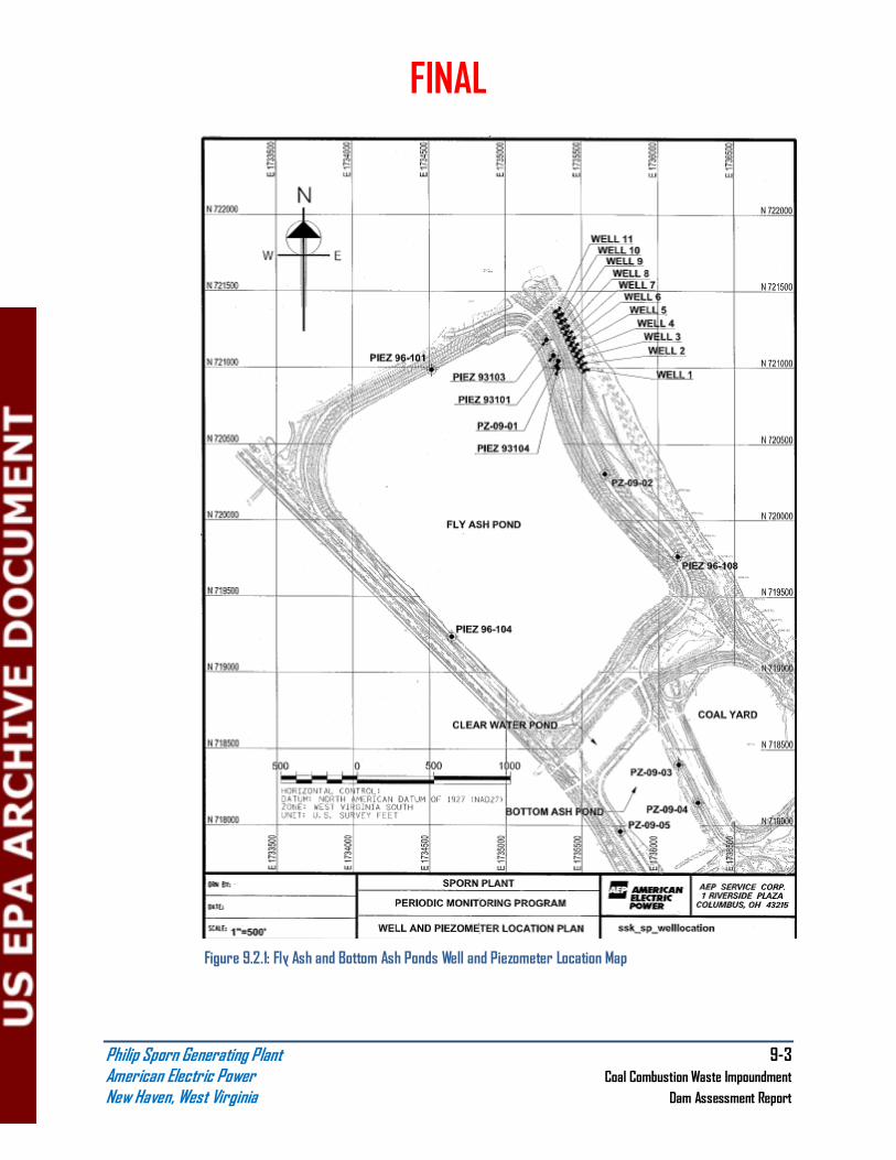
FINAL
Philip Sporn Generating Plant 9-3 American Electric Power Coal Combustion Waste Impoundment
New Haven, West Virginia Dam Assessment Report
Figure 9.2.1: Fly Ash and Bottom Ash Ponds Well and Piezometer Location Map