updated history of construction - ash pond
TRANSCRIPT

UPDATED HISTORY OF CONSTRUCTION FOR EXISTING CCR SURFACE IMPOUNDMENT PLANT GORGAS ASH POND 40 CFR 257.73(c)(1)(i)-(xii)
(i) Site Name and Ownership Information: Site Name: William C. Gorgas Electric Generating Plant Site Location: Parrish, Alabama Site Address: 460 Gorgas Rd.
Parrish, Alabama 36512 Owner: Alabama Power Company Address: 600 North 18th Street
Birmingham, AL 35203 CCR Impoundment Name: Plant Gorgas Ash Pond NID ID: AL01662 EPA’s “Disposal of Coal Combustion Residuals from Electric Utilities” Final Rule (40 C.F.R. Part 257 and Part 261), §257.73(c)(1), requires the owner or operator of an existing CCR surface impoundment to compile a history of construction. To the extent feasible, the following information is provided: (ii) Location of CCR Unit:
33.655691, -87.217915 See Location Map in the Appendix
(iii) Purpose of CCR Impoundment:
The William C. Gorgas Electric Generating Plant is a 3-unit electric generating facility, all of which are coal-fired units. The Plant Gorgas Ash Pond is designed to receive and store coal combustion residuals produced during the electric generating process at Plant Gorgas, as well as serve as a low-volume waste treatment pond. CCR products are sluiced from the plant to the Ash Pond.
(iv) Watershed Description:
Plant Gorgas is located within the Baker Creek-Mulberry Fork HUC 12 watershed which has a total area of 37,044 acres. The Baker Creek-Mulberry Fork Watershed is located within the Mulberry HUC 8 watershed which has a drainage area of 878,212 acres. Approximately 1,302 acres of the surrounding watershed flow into the Ash Pond.

(v) Description of physical and engineering properties of CCR impoundment foundation/abutments:
The Plant Gorgas Ash Pond is located within the Warrior Basin physiographic region of the Cumberland Plateau and is a subsection of the Appalachian Plateaus physiographic province. The Warrior Basin consists of a broad upland with moderate relief, and is formed on gently dipping strata of the Pottsville Formation. The upper reaches of the surface geology are dominated by the Pratt Coal Group and the Cobb Coal Group consisting of shale, siltstone, sandstone, and coal seams. Borings taken in the area suggest that only a thin layer of soil (5 to 20 feet) is present above the Pottsville Formation. The Plant Gorgas Ash Pond is founded on the major soil types present above the rock formations, including clays, silty and clayey sands and decomposed rock.
(vi) Summary of Site Preparation and Construction Activities:
The Ash Pond is formed by a cross-valley dam which was originally constructed as a rockfill structure across Rattlesnake Creek in 1953 using local borrow and quarried materials. The crest elevation of the original dam was 320 feet. In the mid-1970’s, the dam was raised to an elevation of 375 feet. During this construction, a relatively impervious blanket was constructed on the upstream face of the original dam. In addition to the blanket, additional rockfill was added on both the upstream and downstream sides of the dam, as well as the inclusion of a relatively impervious core and filter zone near the interior of the dike raise.
In 2007, the dam was raised to an elevation of 395 feet. During this project, a 10-foot wide roller-compacted concrete upstream facing block designed with a slope of 0.75H:1V; a 30-foot thick clay core section; a 10-foot thick fine and coarse filter section; and additional downstream rockfill were used to accommodate the raising of the dam. The original weir flow intake structure was removed and a new overflow structure of comparable design was constructed near the east abutment. Also, an auxiliary spillway was added at an elevation of 385 feet. During the 2007 augmentation, a diversion dike was added within the ash pond for water management purposes. It is near the midpoint of the surface impoundment, and extends from the east side of the pond to a point very close to the west bank.

(vii) Engineering Diagram:
The following drawings reflecting the construction of the Plant Gorgas Ash Pond can be found in the Appendix:
• 1953 - Original Rockfill Dam Design Section • 2007 - Preconstruction Site Plan • 2007 - General Arrangement and Site Plan • 2007 - Sections and Details • 2007 - New Discharge Structure General Layout, Plan and Sections • 2007 - New Discharge Structure Plan and Sections • 2007 - New Discharge Pipe Plans, Sections and Details
(viii) Description of Instrumentation:
There are six vertical deformation monuments, placed at equal spacing, present across the crest of the dam that serve as the only instrumentation at the facility. These monuments are utilized to track vertical and horizontal displacement along the top of the embankment.
(ix) Area-capacity curves:
0
50
100
150
200
250
300
350
400
450
0
2000
4000
6000
8000
10000
12000
14000
315 325 335 345 355 365 375 385 395
Surf
ace
Area
in A
cres
Cum
ulat
ive
Volu
me
in A
cre-
Feet
Elevation of Pond in Feet (NAVD)
Plant Gorgas Ash Pond Area-Capacity Curve
Volume Capacity Surface Area

(x) Spillway/Diversion design features and capacity calculations:
The primary spillway (constructed in 2007) is a concrete overflow weir structure discharging to a 48-inch diameter corrugated metal pipe. A two-bay concrete spillway structure serves as an auxiliary spillway structure. The spillways are designed, constructed operated and maintained to adequately manage flow during and following the peak discharge from the Probable Maximum Flood (PMF) storm event. Normal pool elevation was calculated to be EL 382-ft and the maximum pool elevation utilizing the 6-hour, PMF design storm hydrograph was EL 389.7-ft, or 5.3 feet below top of dam. Normal flow of the Ash Pond is controlled by the primary spillway. This spillway is capable of carrying 384.2 cubic feet per second (cfs) at a maximum pool elevation of 395.0 feet. The auxiliary spillway would carry 1,100 cfs.
(xi) Provisions for surveillance, maintenance and repair:
Inspections of dams and dikes are critical components and are conducted on a regular basis—at least annually by professional dam safety engineers and at a minimum interval of every seven days by qualified persons at the plant. In addition, inspections are performed after unusual events such as storms. The inspections provide assurance that structures are sound and that action is taken, as needed, based on the findings. Specific items addressed during the inspections include observations of pond levels, weather conditions, rainfall since the prior inspection, instrument readings, conditions of slopes and drains, erosion, animal damage, ant hills, alignment of retaining structures and more. Dam safety engineers assess instrument readings, inspect any maintenance or remediation performed since the previous inspection, check the status of work recommended at prior inspections, ensure that the posting of emergency notification information is up to date and evaluate any items noted during plant personnel inspections.
Construction Specifications:
The following specifications relevant to the construction of the Plant Gorgas Ash Pond can be found in the Appendix:
• 2007 Technical Specifications for RCC Crest Raise • 2007 Crest Raise Notes and Specifications
(xii) Known record of structural instability:
There are no known instances of structural instability at the CCR unit.

Appendix


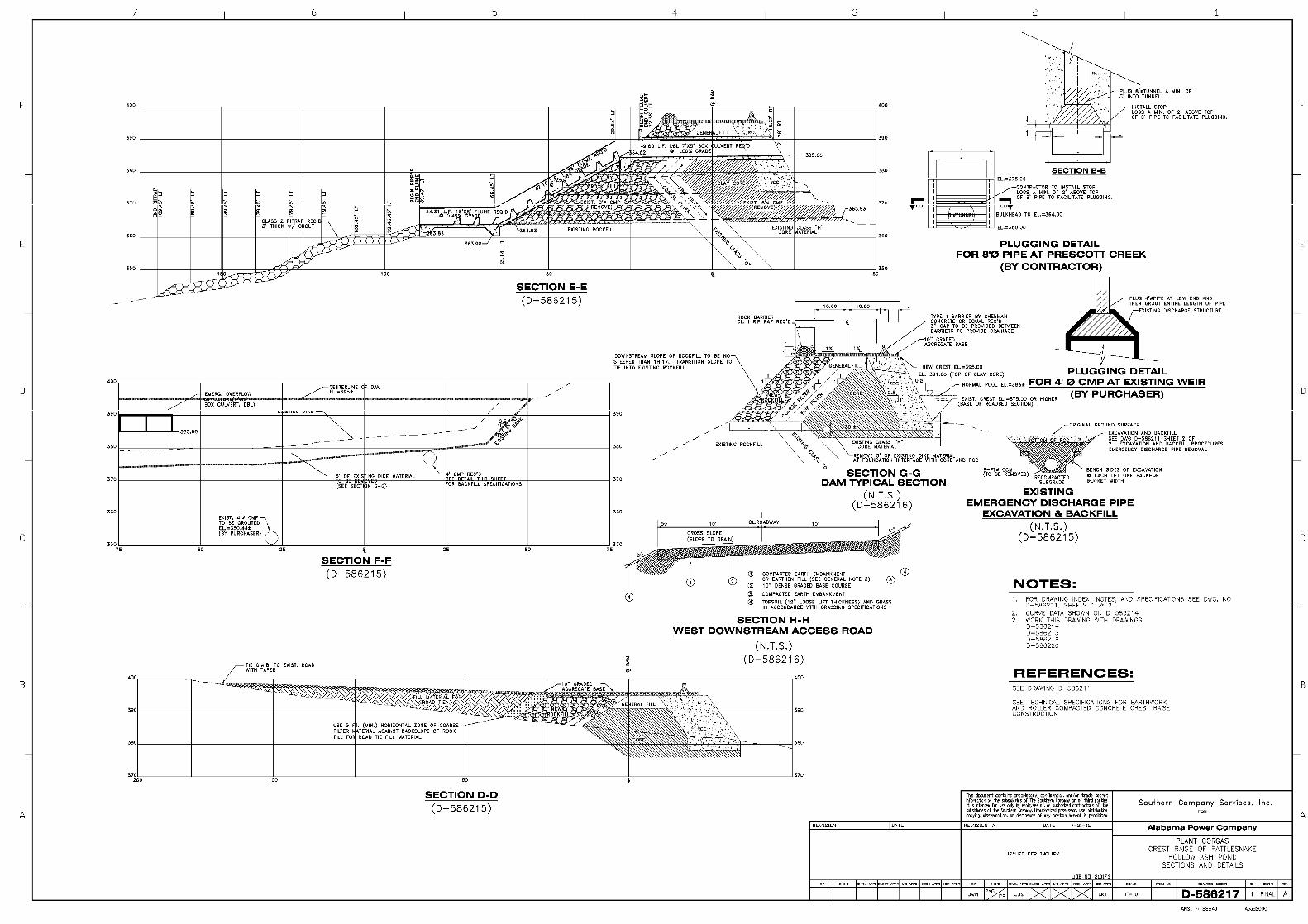
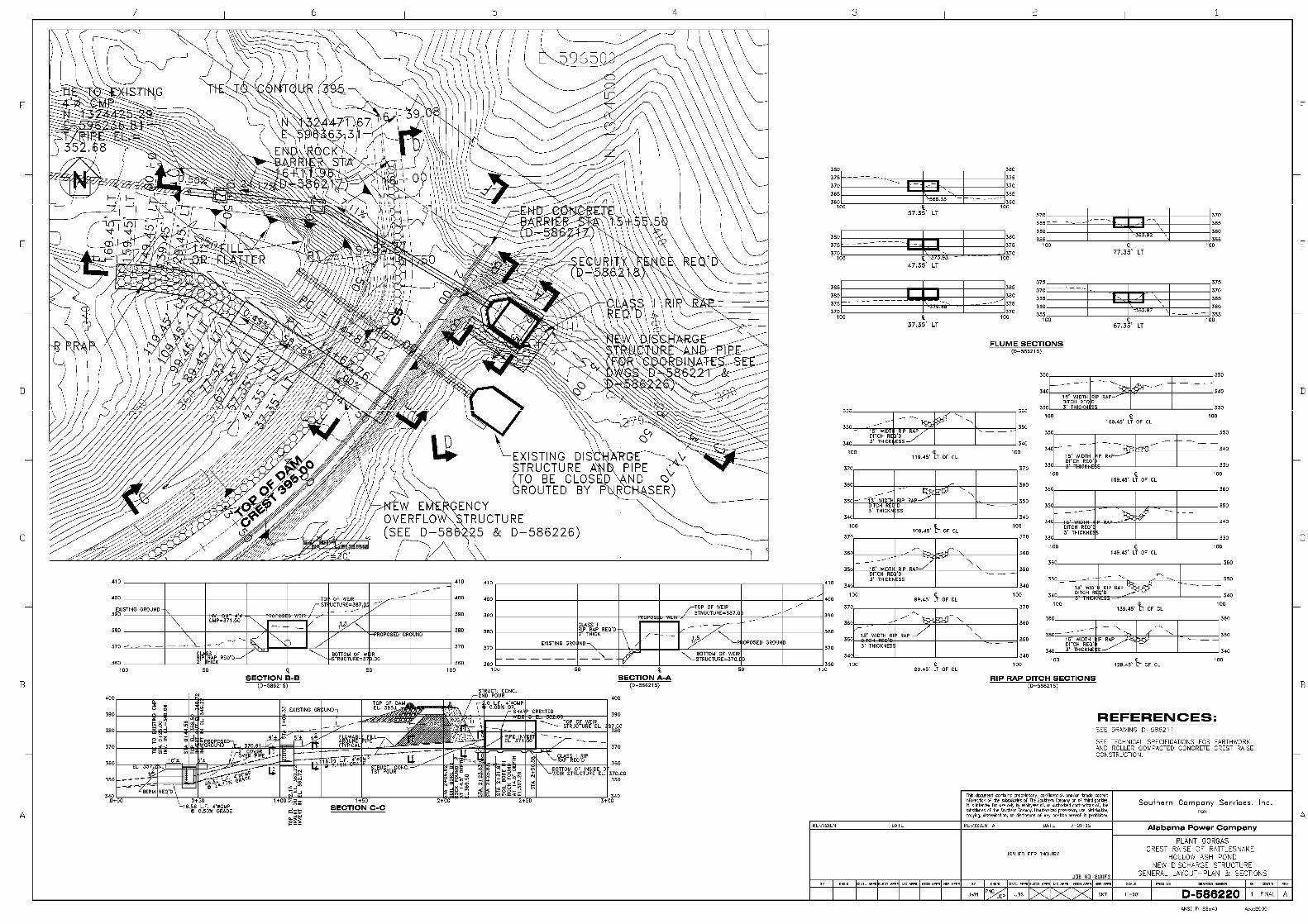


EXHIBIT 4
INQUIRY NO. 000059331
TECHNICAL SPECIFICATIONS FOR
EARTHWORK AND ROLLER COMPACTED CONCRETE CREST RAISE CONSTRUCTION
PLANT GORGAS – RATTLESNAKE HOLLOW ASH POND DAM
ALABAMA POWER COMPANY
PREPARED BY: James C. Pegues___ _ DATE: 12/16/05 REVIEWED BY: Richard M. Franke DATE: 12/16/05 REVIEWED BY: Patrick M. Gordon DATE: 12/16/05 APPROVALS:
INITIAL DATE J. B. SMITH Civil Engineering Supervisor – Fossil and Hydro Projects Engineering and Construction
JBS 12/16/05
REVISIONS: NO DESCRIPTION BY REVIEW APPROVED DATE A Issued for Inquiry JCP RMF/PMG JBS 07/21/06
THIS DOCUMENT CONTAINS PROPRIETARY, CONFIDENTIAL, AND/OR TRADE SECRET INFORMATION OF THE SUBSIDIARIES OF THE SOUTHERN COMPANY OR OF THIRD PARTIES. IT IS INTENDED FOR USE ONLY BY EMPLOYEES OF, OR AUTHORIZED CONTRACTORS OF, THE SUBSIDIARIES OF THE SOUTHERN COMPANY. UNAUTHORIZED POSSESSION, USE, DISTRIBUTION, COPYING, DISSEMINATION, OR DISCLOSURE OF ANY PORTION HEREOF IS PROHIBITED.

ii
EXHIBIT 4
INQUIRY NO. 000059331
TECHNICAL SPECIFICATIONS FOR
EARTHWORK AND ROLLER COMPACTED CONCRETE CREST RAISE CONSTRUCTION
PLANT GORGAS – RATTLESNAKE HOLLOW ASH POND DAM
ALABAMA POWER COMPANY

iii
TABLE OF CONTENTS
1.0 GENERAL .............................................................................................................. 1 1.1 DEFINITION OF TERMS ..................................................................................... 2
2.0 APPLICABLE DOCUMENTS .............................................................................. 2 2.1 CODES AND STANDARDS ................................................................................. 2 2.2 DRAWINGS ........................................................................................................... 4 2.3 FEASIBILITY REPORT ........................................................................................ 4
3.0 CONSTRUCTION REQUIREMENTS .................................................................. 4 3.1 CLEARING, GRUBBING AND STRIPPING ...................................................... 4 3.2 INITIAL EMBANKMENT EXCAVATION AND PREPARATION ................... 4 3.3 EMERGENCY OVERFLOW PIPE EXCAVATION AND REMOVAL.............. 5 3.4 BORROW AREA DEVELOPMENT..................................................................... 5 3.5 ROCK BORROW AREA DEVELOPMENT ........................................................ 6 3.6 MATERIALS .......................................................................................................... 7
3.6.1 Core Material .............................................................................................. 8 3.6.2 Filter/Transition Zone Material................................................................... 8 3.6.3 Rock Fill.................................................................................................... 10 3.6.4 General Fill ............................................................................................... 10 3.6.5 Roller Compacted Concrete ...................................................................... 10
3.6.5.1 Cementitious Materials ......................................................................... 10 3.6.5.2 Water ..................................................................................................... 10 3.6.5.3 Fine Aggregate ...................................................................................... 10 3.6.5.4 Coarse Aggregate .................................................................................. 11 3.6.5.5 Admixtures ............................................................................................ 11
3.6.6 Bedding Concrete...................................................................................... 12 3.6.6.1 Cementitious Materials ......................................................................... 12 3.6.6.2 Water ..................................................................................................... 12 3.6.6.3 Aggregate .............................................................................................. 12 3.6.6.4 Admixtures ............................................................................................ 13
3.7 PLACEMENT....................................................................................................... 13 3.7.1 Earth Fill Materials ................................................................................... 13
3.7.1.1 Lift Thickness ....................................................................................... 13 3.7.1.2 Compaction ........................................................................................... 13 3.7.1.3 Moisture Content .................................................................................. 14
3.7.2 Roller Compacted Concrete ...................................................................... 14 3.7.2.1 Test Section ........................................................................................... 14 3.7.2.2 Surface Preparation ............................................................................... 15 3.7.2.3 Bedding Concrete.................................................................................. 15 3.7.2.4 Lift Thickness ....................................................................................... 15 3.7.2.5 Placement and Spreading ...................................................................... 15 3.7.2.6 Compaction ........................................................................................... 16 3.7.2.7 Curing ................................................................................................... 16 3.7.2.8 Forms .................................................................................................... 16
3.8 TESTING .............................................................................................................. 17 3.8.1 Core Material ............................................................................................ 17

iv
3.8.2 RCC........................................................................................................... 18 4.0 RIGHT OF FIELD INSPECTION........................................................................ 18 5.0 QUALITY CONTROL AND QUALITY ASSURANCE .................................... 18 6.0 EQUIPMENT ....................................................................................................... 18 7.0 VEGETATIVE COVER ....................................................................................... 19 8.0 ENVIRONMENTAL CONTROL MEASURES .................................................. 20
8.1 ENVIRONMENTAL OPERATING PARAMETERS ......................................... 20 8.2 CLEANING .......................................................................................................... 20 8.3 DUST CONTROL ................................................................................................ 21 8.4 POLLUTION CONTROL .................................................................................... 21 8.5 EROSION AND SEDIMENT CONTROL .......................................................... 21
9.0 HAUL ROADS ..................................................................................................... 21 10.0 FINAL INSPECTION AND CERTIFICATION.................................................. 22

1
INQUIRY NO. 000059331
TECHNICAL SPECIFICATIONS
FOR EARTHWORK AND ROLLER COMPACTED CONCRETE
CREST RAISE CONSTRUCTION
PLANT GORGAS – RATTLESNAKE HOLLOW ASH POND DAM
ALABAMA POWER COMPANY 1.0 GENERAL
The purpose of this work is to raise the crest of Rattlesnake Hollow Ash Pond Dam to EL 395 thus increasing the available storage capacity of the ash pond. This is a 20 feet raise above the existing top of dam. Other work associated with the raising of the dam includes, but is not limited to: constructing a new discharge structure and emergency overflow structure; abandoning the existing discharge structure in-place, removing the existing emergency overflow pipe; closing of Prescott Creek tunnel discharge; modification and raising of existing ash sluice lines; modification of existing pontoons and pontoon anchors; construction and installation of new pontoons and anchors; development and operation of borrow areas; realignment and construction of west downstream access road; and improvements and maintenance of other access roads to the site.
Plant Gorgas is a steam electric fossil fueled plant, owned and operated by Alabama Power Company. The plant is located off of Highway 269 along the Black Warrior River near Parrish, Alabama in Walker County. The ash pond is located across the river from the plant. Exhibit 3 - Scope of Work, this Exhibit 4 - Technical Specifications for Earthwork and Roller Compacted Concrete Crest Raise Construction, hereafter referred to as the Technical Specifications, Exhibit 5 - Drawing List, Drawings and contract documents cover the furnishing of all materials (unless otherwise noted), labor, supervision, equipment and tools required by the Contractor. The technical and construction requirements, design data, and specifications are available in the Technical Specifications and on the Drawings. In the case of discrepancies between the Drawings and the Technical Specifications, the Contractor shall notify the Purchaser. In case of discrepancies between the scale dimensions on the Drawings and the dimensions written on them, the written dimensions shall govern. All work shall meet the construction quality control and quality assurance

2
inspection requirements as set forth in the Specifications in Exhibit 4. 1.1 DEFINITION OF TERMS
The terms used herein in this Contractor’s Scope of Work and in the Technical Specifications shall be interpreted and understood as stated:
The term “Contractor” shall be as defined in the General Conditions of the Contract for Construction, SCG-1, Rev. 12 (5-9-2006) (Construction).
The term “Purchaser” shall be as defined in the General Conditions of the Contract for Construction, SCG-1, Rev. 12 (5-9-2006) (Construction).
The term "Project Construction Manager", PCM, denotes the on-site manager of the project or his designated representative. He is the authorized representative at the site for the Purchaser.
The term “QC/QA Inspector” denotes the independent quality control and quality assurance inspector who is provided by the Purchaser. The term “Purchaser’s Engineer” denotes the Purchaser’s SCS Engineering representative.
The terms “Accepted, Acceptable, or Approved” denotes that of which must be acceptable, accepted or approved by the Project Construction Manager or his authorized representative.
2.0 APPLICABLE DOCUMENTS 2.1 CODES AND STANDARDS
The following codes are considered to be a part of these Specifications in the areas where they apply to material, fabrication, workmanship, examination, testing, and documentation. The latest revision in effect at the time of issuance of the Inquiry shall be applicable unless otherwise noted. Omission of any codes and standards does not relieve the Contractor of his responsibility to the applicable codes and standards. In the event of a conflict between the following codes and standards and these Specifications and/or accompanying drawings or diagrams, these Specifications and drawings shall govern to the extent of such conflicts. Any deviations contained in these Specifications and/or accompanying drawings from the following regulations have been made to better address the specifics of this particular facility. A. ASTM Standards
ASTM C31 Standard Practice for Making and Curing Concrete Test Specimens in the Field

3
ASTM C39 Standard Test Method for Compressive Strength of Cylindrical Concrete Specimens
ASTM C136 Standard Test Method for Sieve Analysis of Fine and Coarse Aggregates
ASTM C138 Standard Test Method for Density (Unit Weight), Yield and Air Content (Gravimetric) of Concrete
ASTM C1040 Standard Test Methods for In-Place Density of Unhardened and Hardened Concrete, Including Roller Compacted Concrete, By Nuclear Methods
ASTM C143 Standard Test Method for Slump of Hydraulic-Cement Concrete
ASTM C1116 Standard Specification for Fiber-Reinforced Concrete and Shotcrete
ASTM D422 Standard Test Method for Particle Size Analysis of Soil ASTM D698 Test Method for Laboratory Compaction Characteristics of
Soil Using Standard Effort ASTM D1556 Test Method for Density and Unit Weight of Soil In Place
by the Sand Cone Method ASTM D2216 Standard Test Method for Laboratory Determination of
Water (Moisture) Content of Soil and Rock by Mass ASTM D2487 Classification of Soils for Engineering Purposes (Unified
Soil Classification System) ASTM D2488 Description and Identification of Soils (Visual-Manual
Procedure) ASTM D2922 Test Methods for Density of Soil and Soil – Aggregate In
Place by Nuclear Methods ASTM D2937 Test Method for Density of Soil In Place by the Drive
Cylinder Method ASTM D3017 Standard Test Method for Water Content of Soil and Rock
in Place by Nuclear Methods (Shallow Depth) ASTM D4318 Standard Test Methods for Liquid Limit, Plastic Limit, and
Plasticity Index of Soils ASTM D4643 Test Method for Determination of Water (Moisture)
Content of Soil by the Microwave Oven Method ASTM D4959 Test Method for Determination of Water (Moisture)
Content of Soil by Direct Heating Method
B. American Concrete Institute (ACI) ACI 207.5R Roller Compacted Mass Concrete ACI 304 Recommended Practice for Measuring, Mixing, Transporting,
and Placing Concrete ACI 306 Recommended Practice for Cold Weather Concrete
ACI 309.5R Compaction of Roller-Compacted Concrete C. Occupational Safety and Health Act (OSHA) of 1970, as amended

4
D. Codes specific to the local County and City.
E. Alabama Department of Environmental Management (ADEM) Regulations
F. Environmental Protection Agency (EPA) Regulations 2.2 DRAWINGS
The SCS Design Drawings, hereafter referred to as Drawings, pertinent to the design and construction of this project are listed in Exhibit 5.
2.3 FEASIBILITY REPORT Information about the project background and site conditions were presented in an internal report entitled “Crest Raise Feasibility Study, Rattlesnake Hollow Ash Pond Dam, Gorgas Steam Plant, Alabama Power Company.” Portions of this report containing available soils related data are issued as a portion/exhibit to the Inquiry Package and should be read in their entirety in order that the Contractor is aware of the current dam construction, the engineering characteristics of soils and rock likely to be encountered.
If the Contractor judges that the subsurface information is inadequate in any regard, he has the right to perform any additional investigation to supplement the provided information at no expense to the Purchaser. The Purchaser shall not be liable for any oversight made by the Contractor regarding the subsurface conditions.
3.0 CONSTRUCTION REQUIREMENTS
3.1 CLEARING, GRUBBING AND STRIPPING The surface of the existing embankment and the abutments that lie within the footprint of the area to be raised shall be cleared and grubbed of trees, stumps, and vegetation and stripped of any topsoil. The vegetation, trees, and stumps shall be disposed of in the location designated by the Purchaser. Topsoil shall be stockpiled for later use in restoration of disturbed areas.
3.2 INITIAL EMBANKMENT EXCAVATION AND PREPARATION The upper surface of the existing embankment consists of a layer of soil and soil/rock mixture, as well as roadway surfacing material (red rock), that covers the various embankment zone materials. This upper surface will need to be removed prior to construction of the roller compacted concrete, core material and filter/transition zone. The upper near surface materials should be excavated to a depth of 5 feet below the existing ground surface, as measured at the location of the upstream toe of the roller compacted concrete section. This excavation should

5
extend on a horizontal line towards the downstream to the downstream edge of the filter/transition zone. The Purchaser’s Engineer shall inspect the subgrade after excavation to assess that the expected existing upstream core and transition zone materials are exposed. Undercut materials will be suitable for reuse as general fill in the crest raise above EL 391, as shown on the Typical Dam Section, as long as they meet the requirements of Section 3.6.4 of these Specifications. Prior to placement of the roller compacted concrete, core material and filter/transition zone material, the exposed subgrade shall be compacted with a minimum of 5 passes with a sheepsfoot-type compactor. There are several settlement monitoring monuments on the crest of the dam within the limits of this excavation. These monuments should not be disturbed or damaged in any way, and any excavation around them should be no closer then 5 feet in any direction.
3.3 EMERGENCY OVERFLOW PIPE EXCAVATION AND REMOVAL
The existing emergency overflow pipe is to be removed prior to the raise construction. The pipe should be excavated and removed and the subsequent excavation backfilled in accordance with the notes shown on the Drawings. The excavated pipe should be properly disposed of off-site. The backfilling should proceed upwards in accordance with the applicable notes until the elevation of the bottom of the roller compacted concrete has been reached.
3.4 BORROW AREA DEVELOPMENT A potential borrow area for the core material has been identified just south and west of the west abutment of the embankment. Materials meeting the requirements of the core material as specified in Section 3.4.1 were identified in several test pits to depths of up to about 5 feet below the existing ground surface. However, the Contractor is responsible for sampling, testing, identifying and selective excavation of materials that meet the referenced requirements. The Contractor shall clear, grub, and strip the borrow area to uncover and locate the clayey core material soils. Only those sections of the borrow area required to obtain sufficient fill for immediate crest raise construction should be developed. The Contractor shall be responsible for planning the borrow area activities to support the crest raise construction. The Contractor shall install and maintain erosion control measures in the borrow areas to prevent sediment and erosion activities from affecting wetlands, streams, and surface waters. Section 8.0 addresses erosion control measures.

6
The Contractor shall construct and maintain access roads to and within borrow areas. These roads must be maintained to allow the hauling and vehicle traffic to travel to the active borrow operations. Erosion control measures shall be installed and maintained along access roads to prevent sediment and erosion activities from affecting wetlands, streams, and surface waters. The Contractor shall be responsible for providing and planning dust control measures in the borrow area. The PCM shall direct the Contractor to implement these measures when the PCM determines a dust problem exists. Section 8.3 discusses dust control measures for the borrow areas and access roads. When the Contractor anticipates an upcoming rainfall event, the Contractor shall grade, slope, ditch, and prevent the borrow area from flooding, or affecting nearby wetlands, streams, and surface waters. The Contractor shall construct surface water/sediment runoff ponds, as necessary, to control runoff from rainfall events. The Contractor shall provide a runoff control plan to the PCM within two to five days prior to the start of borrow operations. Upon completion of borrow operations, the Contractor will be responsible for final grading, establishment of vegetative cover and other restoration of the borrow area as determined by the PCM.
3.5 ROCK BORROW AREA DEVELOPMENT A rock quarry was previously developed on the Gorgas property to produce large rockfill stone for construction of the downstream shell of the existing Rattlesnake Hollow Dam. The quarry, which was abandoned after construction, is located downstream and above the west abutment of the dam in an undeveloped area. The rock fill required for the current crest raise is to come from this area. The rock borrow area is overgrown with vegetation and a 20-year growth of scattered pine that will require clearing. Some areas at the toe of the excavated rock are wet and boggy and drainage improvements to facilitate construction traffic may be needed.
The soil cover over the rock is thin and not suitable for use as borrow material in the dam construction. The underlying rock is typical of the coal-bearing Pennsylvanian Pottsville formation found in the area. In the exposed face of the cut, layers of sandstone and weathered shale are visible. The rock ranges from massively-bedded sandstone to shale laminae. The shale will not be suitable for use in the dam and should be separated from the usable rock as much as possible. The Contractor shall be responsible for planning the rock borrow activities to support the crest raise construction.

7
Traffic management, dust control and erosion and sediment control in accordance with the requirements outlined in Section 3.4.6 for the borrow area shall apply to the rock borrow area as well. Blasting will be required to excavate the rock from the rock borrow area. The blasting program has very well defined criteria set forth in the Technical Specifications for Blasting that must be followed, including strict vibration limits, so as to not cause damage to existing structures, including the existing embankment. The Contractor must select one of the specialty contractors listed below to perform the Blasting and shall identify the specialty contractor on his Proposal Form. No substitution will be made without written approval of the Owner. Substitution after the bid opening will not be grounds for changes in bid prices. The specialty contractors who may be used for this portion of the project are the following:
Glenn Barton* Apache Construction 1940 Pinson Valley Parkway Birmingham, Alabama 35217 Phone: 205-849-1727 Fax: 205-849-1726 Eddie Johnson* Blast Pros, Inc. 767 Summerville Road Jasper, Alabama 35504 Phone: 205-522-8230 George Weimer* Boren Explosives Co., Inc. 8425 Highway 269 Parrish, Alabama 35580 Phone: 205-686-5095 Fax: 205-686-5902
* Indicates Prime Contact Name Number in listing in no way represents any order of preference.
3.6 MATERIALS The earth fill materials to be used in constructing the crest raise shall consist of core material, filter/transition zone material and rock fill. The upstream section of the crest raise shall consist of roller compacted concrete. The cross-sections

8
presented on the Drawings show the zones of each fill. The Contractor shall be responsible for obtaining materials from designated on-site sources or from off-site sources which meet the requirements of the Specifications.
3.6.1 Core Material Core material should be obtained from the designated on-site borrow source. Test pits in this area indicate that sufficient quantities of core material are expected to be present within the upper 4 to 5 feet of portions of the designated borrow area. However, the Contractor is responsible for identifying, sampling and testing of materials from this area to confirm their presence.
Core material shall consist of soils having a minimum of 50 percent by weight passing the U.S. Standard No. 200 Sieve (per ASTM D-422). The soils shall also have a liquid limit of at least 30 and a plasticity index of at least 10. The maximum particle size allowed for use in this material shall be 4 inches. The soil shall also have a standard Proctor maximum dry density of at least 100 pcf. These soils shall be classified as CL, ML, or CH materials based on ASTM D-4318 and D-2487).
The Contractor shall obtain three soil samples from the on-site borrow source to verify the soil properties described above. Soil testing shall be performed in accordance with ASTM D-422, D−698, D-2487, and D-4318. This testing work shall be performed and completed at least five days prior to the start of core material placement and compaction activities, including those required for the emergency overflow excavation backfill. All test data shall be submitted for approval to the PCM at least five days prior to the start of core material placement activities.
In the event the Contractor is required to locate an off-site clay fill borrow source to complete the placement work, the Contractor shall perform the same soil sampling, testing, and submittal activities as stated above. The PCM shall approve the new off-site borrow source prior to the Contractor utilizing these clay soils in the crest raise construction.
Soil sampling and testing shall be performed on each observed change in soil consistency (determined by the Contractor’s field supervisor or the PCM) or for each 5000 cubic yards of clay soil used in the core construction, whichever occurs first. The Contractor shall perform all sampling and testing work at no additional cost to the Purchaser.
3.6.2 Filter/Transition Zone Material
The filter/transition zone will be constructed between the core material and the downstream rock fill, and will be a split, or two zone, system. The full width of the filter transition zone is to be a minimum of 10 feet. The upstream side of the

9
filter that will be adjacent to the core will be a minimum of 5 feet wide, and consist of material having the following gradation, which is comparable to ALDOT No. 100 concrete sand:
Gradation Requirements Upstream Section of Filter/Transition Zone Material
Sieve Size Percent Passing by Weight
3/8-in 100 No. 4 95-100 No. 8 80-100 No. 16 50-90 No. 50 5-30 No. 100 0-10
The downstream section of the filter that will be placed adjacent to the rock fill will have a minimum width of 5 feet and will consist of material having the following gradation, which is comparable to ALDOT No. 57 coarse aggregate:
Gradation Requirements Downstream Section of Filter/Transition Zone Material
Sieve Size Percent Passing by Weight
1.5-in 100 1-in 95-100
0.5-in 25-60 No. 4 0-10 No. 8 0-5
The filter/transition zone material can be processed sandstone from the on-site rock borrow area operations or can be processed limestone/dolomite from an off-site source. The Contractor shall obtain three samples each of both filter/transition zone materials to verify the gradation properties described in this Section above. Testing shall be performed in accordance with ASTM D-422. This testing work shall be performed and completed and all test data shall be submitted for approval to the PCM at least five days prior to the start of filter/transition zone placement activities. Sampling and testing shall be performed on each filter/transition zone material for each 1000 cubic yards used in the crest raise construction. The Contractor shall perform all sampling and testing work at no additional cost to the Purchaser.

10
3.6.3 Rock Fill
Rock fill for placement on the downstream section of the crest raise will be obtained from an on-site rock borrow area located northwest of the west abutment. Rock fill from this area should consist predominately of sandstone, with less than 5 percent by weight of intact shale allowed in each load of material. The particle size of the rock fill shall range from 1-in minimum to 24-in maximum, with at least 50 percent by weight larger than 12 inches, with an allowable oversize tolerance of 5 percent.
3.6.4 General Fill General fill will be used to construct the portion of the crest raise above EL 391 feet, between the upstream Roller Compacted Concrete and the downstream rock fill. General fill shall consist of non-organic soils and/or rock, with a maximum particle size of 12 inches. Also, the soils used as general fill shall also have a liquid limit of at less than 50 and a plasticity index less than 30.
3.6.5 Roller Compacted Concrete Roller compacted concrete (RCC) will be used to construct the upstream section of the crest raise. The RCC shall be proportioned by the Contractor so as to attain a compressive strength at 28 days of 3000 psi. The RCC shall be composed of cementitious materials, water, fine and coarse aggregate, and admixtures.
3.6.5.1 Cementitious Materials
Cementitious materials shall consist of Portland cement and pozzolan. The Portland cement shall conform to ASTM C 150, Type II. Pozzolan shall conform to ASTM C 618, Type F Fly Ash. The pozzolan percentage of cementitious material shall not exceed 50 percent. 3.6.5.2 Water Water shall be free of injurious amounts of oil, acid, salt, alkali, organic material or other deleterious substances. Water from the ash pond shall not be used. 3.6.5.3 Fine Aggregate
11
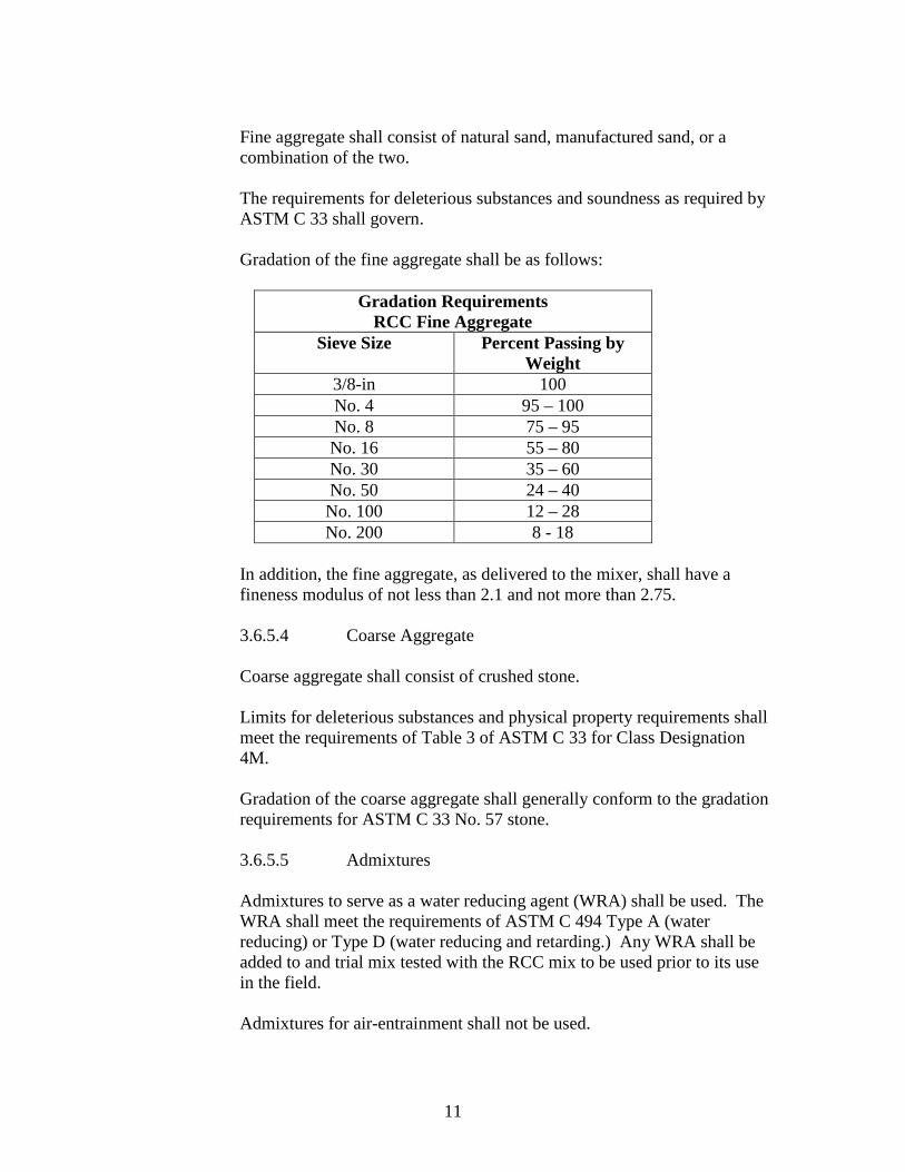
Fine aggregate shall consist of natural sand, manufactured sand, or a combination of the two. The requirements for deleterious substances and soundness as required by ASTM C 33 shall govern. Gradation of the fine aggregate shall be as follows:
Gradation Requirements RCC Fine Aggregate
Sieve Size Percent Passing by Weight
3/8-in 100 No. 4 95 – 100 No. 8 75 – 95 No. 16 55 – 80 No. 30 35 – 60 No. 50 24 – 40 No. 100 12 – 28 No. 200 8 - 18
In addition, the fine aggregate, as delivered to the mixer, shall have a fineness modulus of not less than 2.1 and not more than 2.75.
3.6.5.4 Coarse Aggregate Coarse aggregate shall consist of crushed stone. Limits for deleterious substances and physical property requirements shall meet the requirements of Table 3 of ASTM C 33 for Class Designation 4M. Gradation of the coarse aggregate shall generally conform to the gradation requirements for ASTM C 33 No. 57 stone. 3.6.5.5 Admixtures
Admixtures to serve as a water reducing agent (WRA) shall be used. The WRA shall meet the requirements of ASTM C 494 Type A (water reducing) or Type D (water reducing and retarding.) Any WRA shall be added to and trial mix tested with the RCC mix to be used prior to its use in the field. Admixtures for air-entrainment shall not be used.

12
3.6.6 Bedding Concrete
Bedding concrete will be used to increase the bond between RCC lifts. The Bedding Concrete shall be proportioned by the Contractor, and shall be designed with a slump range of 5-in to 7-in. The mix shall contain a minimum of 500 pounds per cubic yard of cementitious materials.
The Bedding Concrete shall be composed of cementitious materials, water, aggregate, and admixtures.
3.6.6.1 Cementitious Materials
Cementitious materials shall consist of Portland cement and pozzolan. The Portland cement shall conform to ASTM C 150, Type II. Pozzolan shall conform to ASTM C 618, Type F Fly Ash. The pozzolan percentage of cementitious material shall not exceed 30 percent. 3.6.6.2 Water Water shall be free of injurious amounts of oil, acid, salt, alkali, organic material or other deleterious substances. Water from the ash pond shall not be used. 3.6.6.3 Aggregate Aggregate shall consist of crushed stone materials. The requirements for deleterious substances and soundness as required by ASTM C 33 shall govern. Gradation of the aggregate shall conform to the requirements of ALDOT No. 8910 stone, as follows:
Gradation Requirements Bedding Concrete Aggregate
Sieve Size Percent Passing by Weight
1/2-in 100 3/8-in 90 – 100 No. 4 60 - 85 No. 8 40 - 70 No. 50 10 – 25 No. 200 1 - 5

13
3.6.6.4 Admixtures
Admixtures to serve as a water reducing agent (WRA) and retarder shall be used. The WRA shall meet the requirements of ASTM C 494 Type D (water reducing and retarding.)
3.7 PLACEMENT
3.7.1 Earth Fill Materials The Contractor shall be responsible for the placement of fill materials, which includes the clay core materials, the filter materials and the rockfill. The placement activities will include: the excavation and loading of materials from the borrow source into hauling equipment, transporting the materials to the crest raise placement area, dumping and spreading the materials into lifts, and compacting the material to the designated density level. The Contractor shall provide an adequate number of laborers to remove roots and other unacceptable debris from each lift of earth material. When the Contractor anticipates an upcoming rainfall event, the top surface of the compacted lift of core material should be rolled with a smooth-drum roller or bladed with the dozer or scraper to seal the lift surface to facilitate rainfall runoff.
3.7.1.1 Lift Thickness The lifts of core material, including the initial lift, shall be placed in lifts, each with a loose thickness not to exceed 8 inches. The lift of filter materials, including the initial lift, shall be placed in lifts, each with a loose thickness not to exceed 12 inches.
The rock fill shall be placed in loose lift thickness not to exceed 30 inches.
3.7.1.2 Compaction For the clay core and general fill material, the in-place density shall be a minimum of ninety-five percent (95%) of the material’s maximum dry density as per the Standard Proctor designation, ASTM D-698. The in-place density should be obtained by using sheepsfoot type compaction equipment. For the filter material, compaction shall be achieved with a minimum of 4 passes per lift with a smooth-drum vibratory roller or sled-type vibratory compactor. For rock fill material, compaction shall be achieved with a minimum of 5 passes of a vibratory steel-drum roller having a static weight of at least 8 tons and a

14
minimum operating dynamic force of 15 tons. Large rubber-tired equipment may also be used in combination with vibratory rollers.
3.7.1.3 Moisture Content The moisture content of the core material during placement and compaction activities shall be in the range of one percent below to three percent above the optimum moisture content of the soil, based on the ASTM D-698 designation. The filter material shall be moist enough at the time of placement and compaction activities to “lubricate” the particles to facilitate compaction while at the same time not create unstable support conditions such as pumping and rutting.
Moisture conditioning of the rock fill materials will assist in filling voids by washing of soil fines and smaller particles between the larger rock particles. Wetting of the rock fill should be accomplished following compaction of each lift and prior to the placement of additional lifts. The rock fill lift should not be wetted prior to compaction unless the rock fill is relatively free of fines and rapidly drains prior to compaction.
If the water content is less than the specified level for compaction, the compaction operations shall not proceed until the water content is brought into an acceptable range. Moistening of the core and filter materials shall be performed at the site of compaction. If the water content is greater than the specified level for compaction, the compaction operations shall be delayed until such time as the material has dried to the specified water content. Drying of the material may be accelerated by utilizing a harrow, disc, or similar equipment.
3.7.2 Roller Compacted Concrete
The Contractor shall be responsible for the placement of the RCC, including: the mixing and loading of materials into hauling equipment, transporting the materials to the crest raise placement area, dumping and spreading the materials into lifts, and compacting the material to the designated density level. The intent is to construct the raise at essentially the same level across the entire horizontal surface. Preferably, the placement and compaction of the RCC should proceed from abutment to abutment. Initially, some modification to this procedure and “partial” lift placement may be needed as the existing dam crest is not on a level plane.
3.7.2.1 Test Section Prior to the placement of any RCC, the contractor shall construct a test section in an approved location outside the footprint of the crest raise. The purpose of the test section is to demonstrate the suitability of the Contractor’s equipment,

15
procedures, methods and training of personnel. The test section shall demonstrate plant batching and mixing capabilities, as well as transporting, spreading and compaction procedures. The test section will also allow for an evaluation of design mix performance for both the RCC and the bedding concrete, and will allow for determination of a target density to use for quality control during construction. The test section shall be at least 2 lifts thick and shall be at least 10 feet wide and 30 feet long. The Contractor shall not begin work on the crest raise until all evaluations and testing of the test section are complete and approved by the PCM. If the Contractor does not meet the requirements as specified, an additional test section(s) shall be constructed at no additional costs to the Purchaser.
3.7.2.2 Surface Preparation
The initial lift of RCC shall be placed on the subgrade prepared as specified in Section 3.2. All additional lift surfaces, including any RCC and bedding concrete, shall be cleaned prior to the placement of additional concrete. All surfaces shall be free of ponded or other visible free water, soil, mud or loose rock. In addition, the surface of any RCC lift shall be moist prior to the placement of bedding concrete. Cleaning methods shall not damage existing RCC lifts such as by undercutting coarse aggregate and/or washing away cement paste.
3.7.2.3 Bedding Concrete Bedding concrete shall be applied to any existing RCC surface after any needed cleaning is complete and prior to the placement of additional RCC. The thickness of the bedding concrete shall be between 1 and 2 inches. The bedding concrete shall be placed no more than 15 minutes ahead of the RCC. Bedding concrete shall also be used at the RCC-abutment interface where any sloping or vertical surfaces are present.
3.7.2.4 Lift Thickness
The total thickness of each lift of the RCC after compaction shall not exceed 12 inches.
3.7.2.5 Placement and Spreading
The RCC can be transported to the crest raise area and placed with conveyors, end-dump trucks, scrapers or bottom-dump trucks, or any combination thereof.
16
Care must be taken to not track or deposit soil, rocks, mud or other deleterious material on the RCC surface during transport and placement. After placement, the RCC can be spread with a dozer or other similar, approved equipment. The use of specialized spreaders is also acceptable. Means and methods to protect the surface of recently placed and compacted RCC from the treads of dozers or other equipment should be taken. The RCC should be spread to provide a uniform surface capable of uniform compaction. Care should be taken to not segregate materials during the spreading process.
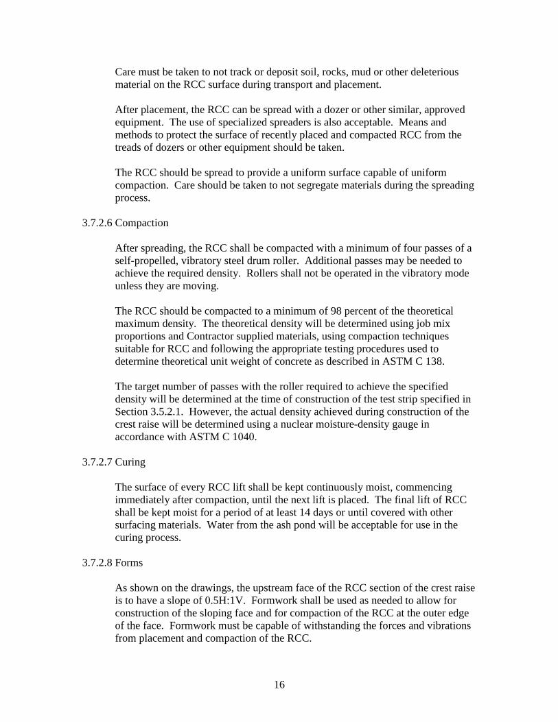
3.7.2.6 Compaction
After spreading, the RCC shall be compacted with a minimum of four passes of a self-propelled, vibratory steel drum roller. Additional passes may be needed to achieve the required density. Rollers shall not be operated in the vibratory mode unless they are moving. The RCC should be compacted to a minimum of 98 percent of the theoretical maximum density. The theoretical density will be determined using job mix proportions and Contractor supplied materials, using compaction techniques suitable for RCC and following the appropriate testing procedures used to determine theoretical unit weight of concrete as described in ASTM C 138. The target number of passes with the roller required to achieve the specified density will be determined at the time of construction of the test strip specified in Section 3.5.2.1. However, the actual density achieved during construction of the crest raise will be determined using a nuclear moisture-density gauge in accordance with ASTM C 1040.
3.7.2.7 Curing
The surface of every RCC lift shall be kept continuously moist, commencing immediately after compaction, until the next lift is placed. The final lift of RCC shall be kept moist for a period of at least 14 days or until covered with other surfacing materials. Water from the ash pond will be acceptable for use in the curing process.
3.7.2.8 Forms
As shown on the drawings, the upstream face of the RCC section of the crest raise is to have a slope of 0.5H:1V. Formwork shall be used as needed to allow for construction of the sloping face and for compaction of the RCC at the outer edge of the face. Formwork must be capable of withstanding the forces and vibrations from placement and compaction of the RCC.

17
Formwork to be used in the construction of the crest raise shall be included in the construction of the required test strip for evaluation.
3.8 TESTING The Contractor shall employ and pay for the services of an independent testing laboratory to perform specified earthwork testing. The Contractor shall cooperate with the laboratory to facilitate the execution of its required services. Employment of the laboratory shall in no way relieve the Contractor of his obligations to perform the work and supply the materials in accordance with the Specifications. The Contractor shall have the following responsibilities: A. Cooperation with laboratory personnel and provision of access to the work
area and to the Contractor’s operations;
B. Securing for the laboratory personnel adequate quantities of representative samples of materials proposed to be used and which require testing;
C. Furnishing copies of the product test reports as required;
3.8.1 Core Material
A. Field density and moisture content testing shall be performed to verify that
compaction requirements have been achieved. In-place field density testing of the compacted core material shall be performed in accordance with the procedure, ASTM D 1556-82, the sand cone method. Test results reported should include both the moisture content and dry density, along with other data such as location, elevation, and Proctor curve used for comparison, etc.
B. Testing of in-place density and moisture content by nuclear methods ASTM
D 2922-81 and ASTM D 3017-88, respectively, describe these testing procedures and may be used provided: 1) acceptable correlation with sand cone density test results can be obtained according to the guidelines of Section 7, “Calibration”, of ASTM D-2922, and 2) the initial correlation results are reviewed and use of the nuclear device is approved by the Purchaser’s Engineer. In addition, it shall be required that the PCM or his testing agency or representative have the necessary licenses to operate a nuclear energy source, and to take all safety precautions per Section 6 of ASTM D-2922.
C. In the event of repeated failures, or water content and density test values
plotting far from the Proctor curves used for comparison in computing percent compaction, it shall be the option of the PCM to require one or two-point Proctor checks (on the dry side of optimum) to verify that the proper Proctor curve is being referenced. If not, a new Proctor curve determined by a five-

18
point test shall be required. The Contractor shall sample and perform the five-point testing, all at the Contractor’s expense.
D. If the compaction requirements for a lift have not been achieved, the PCM
shall direct the Contractor to either rework the lift to obtain the compaction requirements or remove and replace with a new lift for compaction, all at the Contractor’s expense.
E. The in-place density testing frequency for the core material shall be one test
for each 10,000 square feet of lift area or portion thereof for each lift, with a minimum of three tests per lift.
3.8.2 RCC
A. Field density testing shall be performed to verify that compaction requirements have been achieved. In-place field density testing of the compacted core material shall be performed in accordance with the procedures of ASTM C 1040. Test results reported should include test method used (direct transmission or backscatter), density values, and other requirements of the ASTM standard. The testing equipment shall be calibrated as per the standard.
B. The in-place density testing frequency for the RCC shall be one test for each
2,500 square feet of lift area or portion thereof for each lift, with a minimum of five tests per lift.
4.0 RIGHT OF FIELD INSPECTION The Purchaser shall have the right to inspect the Contractor’s work as deemed necessary. The Purchaser shall have the right to inspect the Contractor’s work locations, the materials in use, and to follow the progress of the work and the manner in which it is being done. The Purchaser shall have the authority to reject materials or suspend any work not being properly performed or that is not in accordance with these Specifications. The Contractor has the responsibility for his work being performed properly and in accordance with these Specifications and the presence of an inspection shall not relieve the Contractor or his responsible agents of that responsibility.
5.0 QUALITY CONTROL AND QUALITY ASSURANCE
The Contractor shall implement approved quality control plans, programs, or practices, and shall institute any additional controls or procedures in accordance with proven industry practice to assure compliance with the Special Conditions, Scope of Work, Technical Specifications, and Drawings.
6.0 EQUIPMENT

19
The Earthwork Contractor shall be responsible for providing all equipment necessary to perform the work set forth in these Specifications. The Contractor shall be responsible for maintaining the equipment during the contract period. Any delays in work activities due to equipment maintenance must be reported to the PCM for determination of impacts on the schedule. The Contractor shall be responsible for the cleaning of haul and other vehicles. The Contractor shall wash down the wheels, outside body, cab, undercarriage, etc., of all haul vehicles to prevent spreading of material during transit of the equipment out of the boundary of the working area or onto the RCC surface. All the Contractor’s equipment shall be operated in a safe, careful manner in accordance with these Specifications.
7.0 VEGETATIVE COVER
A. Establishment of vegetative cover shall be performed on all slopes and disturbed top surfaces of the abutments adjoining the crest raise. Establishment of vegetation shall also be performed in the disturbed areas of the borrow pit, where exposed soils are present in the rock borrow area, and along any haul roads used and/or constructed by the Contractor.
B. The PCM may direct the Contractor to establish vegetation in other areas of
the site at an additional cost decided upon by the PCM and Contractor.
C. The Contractor shall produce a satisfactory stand of perennial vegetation. If it is necessary to repeat any or all the work, including plowing, fertilizing, watering, mulching and seeding, the Contractor shall repeat these operations until a satisfactory stand is obtained at no additional cost to the Purchaser.
D. All disturbed areas shall be established with vegetation as indicated by the
Purchaser. Hydroseeding methods may be used upon approval of the mix by the PCM.
E. A satisfactory stand of vegetation is defined as a full cover of perennial plants
that are alive and growing during the first growing season following seed application that is acceptable to the PCM.
F. Measures shall be taken to prevent erosion of the topsoil layer and vegetation
until a full vegetative growth has been obtained.
G. Water required to promote a satisfactory growth shall be furnished and applied by the Contractor.
H. Coordinate seeding with other work.

20
I. Contractor must comply with regulatory agencies for fertilizer and herbicide
composition. 8.0 ENVIRONMENTAL CONTROL MEASURES
8.1 ENVIRONMENTAL OPERATING PARAMETERS
The Contractor shall comply with and abide by all environmental laws, regulations, and permit stipulations which govern the operation of Plant Gorgas and its ash pond. These include but are not limited to the following permits:
• NPDES Permit No. AL-0002909 • Construction Stormwater Permit (to be obtained by Alabama Power
Company for this project)
The rules and regulations include but are not limited to the following:
• The Clean Air Act of 1990, as amended
• The Federal Water Pollution Control Act
• Alabama Solid Waste Regulations
The Contractor shall be solely responsible for any penalties and restoration costs associated with the failure to comply with the above stipulations. Failure of the Contractor to conform to the Environmental Operation Parameters, as determined by the PCM shall constitute a breach of contract. The Contractor shall provide equipment and personnel to perform emergency measures required to contain any spillages and to remove contaminated soils or liquids and shall excavate and dispose of any soil contaminated by the construction operations off-site, and replace such soil with suitable compacted fill and topsoil as directed by the PCM. The Contractor shall take special measures to prevent harmful substances from entering public waters and shall prevent disposal of wastes, effluents, chemicals, sediments, or other such substances adjacent to streams, or in sanitary or storm sewers.
8.2 CLEANING The Contractor shall conduct cleaning and disposal operations to comply with all codes, ordinances, regulations, and anti-pollution laws. Disposal of acceptable materials shall be to the ash pond, as determined by the PCM. Only those cleaning materials which will not create hazards to health or property and which

21
will not damage surfaces shall be used. Only those cleaning materials and methods recommended by the manufacturer of the surface material to be cleaned shall be used and cleaning materials shall be used only on those surfaces recommended by the material manufacturer. The Contractor shall perform periodic cleaning to keep the work, the site, and adjacent properties free from accumulation of waste materials, rubbish, and windblown debris resulting from construction operations. The Contractor shall provide on-site containers for the collection of waste and shall periodically remove waste materials from the site and dispose of such materials in legal disposal areas away from the site.
8.3 DUST CONTROL The Contractor shall continually take steps necessary to minimize dust created by all equipment, vehicles, work activities, or storage areas. These steps shall include, but not be limited to, watering roads and work areas. Open-bodied trucks handling sand, stone, gravel, or earth shall be covered if the truck is traveling off site. The Contractor shall not deposit mud or debris on public road, plant roads, or adjacent properties.
8.4 POLLUTION CONTROL The Contractor shall provide methods, means, and facilities to prevent contamination of soil, water, and atmosphere from discharge of noxious and/or toxic substances, fueling stations, and pollutants produced by construction operations. Toxic liquids, chemicals, fuels, lubricants, etc., shall be deposited into properly labeled containers for subsequent removal offsite in accordance with all applicable Federal, State, and local codes and standards.
8.5 EROSION AND SEDIMENT CONTROL The Contractor shall provide, implement, and maintain the sediment and erosion control measures described in the plan submitted with the bid. The plan and associated measures will be approved by the PCM prior to the start of construction. The Contractor shall provide the measures for the entire contract period.
9.0 HAUL ROADS It shall be the responsibility of the Contractor to maintain the existing haul roads, ramps, and associated culverts and ditching, and, with the express approval of the PCM, to design and construct any additional necessary ramps and/or haul roads, as required for his use and mode of operation. The ramps and haul roads shall be

22
maintained in good condition throughout the contract period. The PCM must approve the source of materials required to construct and maintain the haul roads and ramps. The Contractor shall be responsible for preventing dust problems, equipment tracking mud and soil clods onto County or State roads and highways, and the cleaning of the road surface from equipment usage as per the direction and to the satisfaction of the PCM. The Contractor shall maintain all access roads used by the Contractor’s hauling and vehicular equipment. The Contractor shall grade and repair roads daily to remove potholes, ruts, irregularities and slumps which develop in the road surface.
10.0 FINAL INSPECTION AND CERTIFICATION The work in this inquiry shall be considered complete after the following: A. All newly constructed improvements have been turned over to the Purchaser’s
representative for final inspection and acceptance.
B. A stand of vegetation shall be established such that there is a live, healthy covering of plants acceptable to the PCM 6 months from the time of planting. Furthermore, a stand of vegetation is established by “end of project plus eight weeks” per ALDOT specifications.
C. The survival rate for installed vegetation is at least 80% one year from the
time of planting.
D. Contractor’s work area is orderly and properly restored.
E. Contractor’s equipment and materials have been removed from site.
F. The Contractor shall submit to the Purchaser a Project Completion Report including the following:
• Summary of slope stabilization work by area, along with progress and
finish photos. • QA/QC documentation • Markups for as-built construction drawings. • RCC, core soils and filter/transition zone material testing results. • Applicable permits. • Other documents as considered applicable and as notified to the
Contractor by Purchaser at least 2 weeks prior to the estimated completion date.

