co2 storage capacity estimation: issues and development of standards
TRANSCRIPT

i n t e r n a t i o n a l j o u r n a l o f g r e e n h o u s e g a s c o n t r o l 1 ( 2 0 0 7 ) 6 2 – 6 8
CO2 storage capacity estimation: Issues and developmentof standards
John Bradshaw a,*, Stefan Bachu b, Didier Bonijoly c, Robert Burruss d,Sam Holloway e, Niels Peter Christensen f, Odd Magne Mathiassen g
aGeoscience Australia, GPO Box 378, Canberra, ACT 2601, AustraliabAlberta Energy and Utilities Board, 4999-98th Avenue, Edmonton, AB T6B 2X3, CanadacBRGM-CDG/DIR 3, avenue Claude Guillemin BP 6009 45060 Orleans cedex 2, FrancedUS Geological Survey, National Center MS 956, 12201 Sunrise Valley Drive, Reston, VA 20192, USAeBritish Geological Survey, Keyworth Nottingham NG12 5GG, UKfGeological Survey of Denmark & Greenland (GEUS), Vester Voldgade 10, DK-1250 Copenhagen K, DenmarkgNorwegian Petroleum Directorate, P.O. Box 600, N-4003 Stavanger, Norway
a r t i c l e i n f o
Article history:
Received 1 August 2006
Received in revised form
5 February 2007
Accepted 6 February 2007
Published on line 26 March 2007
Keywords:
CO2
Storage capacity
Trapping efficiency
a b s t r a c t
Associated with the endeavours of geoscientists to pursue the promise that geological
storage of CO2 has of potentially making deep cuts into greenhouse gas emissions, Govern-
ments around the world are dependent on reliable estimates of CO2 storage capacity and
insightful indications of the viability of geological storage in their respective jurisdictions.
Similarly, industry needs reliable estimates for business decisions regarding site selection
and development. If such estimates are unreliable, and decisions are made based on poor
advice, then valuable resources and time could be wasted. Policies that have been put in
place to address CO2 emissions could be jeopardised. Estimates need to clearly state the
limitations that existed (data, time, knowledge) at the time of making the assessment and
indicate the purpose and future use to which the estimates should be applied. A set of
guidelines for estimation of storage capacity will greatly assist future deliberations by
government and industry on the appropriateness of geological storage of CO2 in different
geological settings and political jurisdictions. This work has been initiated under the
auspices of the Carbon Sequestration Leadership Forum (www.cslforum.org), and it is
intended that it will be an ongoing taskforce to further examine issues associated with
storage capacity estimation.
Crown Copyright # 2007 Published by Elsevier Ltd. All rights reserved.
avai lable at www.sc iencedi rec t .com
journal homepage: www.e lsev ier .com/ locate / i jggc
1. Introduction
Estimation of the capacity of a geological reservoir to store CO2
is not a straightforward or simple process. Some authors have
tried to make simplistic estimates at the regional or global
level, but have largely been unsuccessful, as shown by widely
conflicting results (Fig. 1). At the worldwide level, estimates of
* Corresponding author at: Cnr Jerrabomberra Avenue, And Hindmarsfax: +61 2 6249 9920.
E-mail address: [email protected] (J. Bradshaw).
1750-5836/$ – see front matter. Crown Copyright # 2007 Published bdoi:10.1016/S1750-5836(07)00027-8
the CO2 storage potential are often quoted as ‘‘very large’’ with
ranges for the estimates in the order of 100 to 10,000 s Gt CO2.
Although in principle storage capacity estimation relies on a
simple series of algorithms that depend on the storage
mechanism under consideration to calculate the available
capacity in a certain volume of sedimentary rock at a given
depth, temperature and pressure, applying them to a specific
h Drive, Symonston, ACT 2609, Australia. Tel.: +61 2 6249 9659;
y Elsevier Ltd. All rights reserved.

Fig. 1 – A listing of various estimates for CO2 storage capacity for the world and regions of the world. Estimates are listed by
region, and ordered internally by date of completion of the estimates. Note there are world estimates (a) that are smaller
than some more ‘‘robust’’ regional estimates (b).
i n t e r n a t i o n a l j o u r n a l o f g r e e n h o u s e g a s c o n t r o l 1 ( 2 0 0 7 ) 6 2 – 6 8 63
region or site is complex. It is particularly difficult due to the
various trap types and trapping mechanisms that can occur,
the different time frames over which trapping becomes
effective, and the different physical states in which the CO2
might occur (Table 1). All these parameters affect the
effectiveness of geological storage of CO2, often in different
directions. The highly variable nature of geological settings,
rock characteristics, and reservoir performance combine to
make some estimates unreliable when they are made with
methodologies that generalise the inputs for evaluating
potential storage capacity.
There are many levels of uncertainty within assessments
of storage capacity. The different levels of assessment require
extensive datasets from multiple disciplines that must be
integrated to develop meaningful assessments. The most
accurate way to estimate storage capacity at the local scale is
through construction of a geological model and use of that
information in reservoir simulations. Such analyses are
resource, time and data intensive. Given the significant
variability that exists in many estimates and in their under-
lying criteria, it is necessary to document the limitations of
many of the assumptions used, and to make suggestions and
give examples of how better and more reliable estimates can
be determined. At the same time, a series of definitions needs
to be established to provide consistency between capacity
estimates and in understanding and comparing various
capacity figures. This paper provides preliminary guidance
on a number of issues associated with storage capacity
estimation, and is being followed by further more detailed
work looking at practical implementation of the concepts and
guidelines described in this paper.
2. Existing capacity estimates
A large proportion of existing capacity estimates are highly
variable and in many instances are contradictory. Although
geoscience professionals are able to examine the details and
underlying assumptions of each report (if documented) to see
if they have used appropriate and consistent methodologies,
non-geoscientists will often only look at the final ‘‘bottom
line’’ number and can be misled or subsequently mislead
others if they use the values in a way for which they were
never intended. This phenomenon is not uncommon in
resource assessments of mineral and fossil fuel resources.
Additional problems with the estimates of storage capacity
relate to whether the assessments were conducted at the
reserve or resource level, and the assumptions that were made

Table 1 – Characteristics of physical and chemical trapping mechanisms
Trappingmechanism
Characteristics
Nature oftrapping
Effective timeframe
Areal size Occurrencein basin
Issues Capacitylimitation/benefits
Potentialsize
Capacityestimationmethod/
requirements
Structural and
stratigraphic
Bouyancy trapping
within anticline,
fold, fault block,
pinch-out. CO2
remains as a fluid
below physical
trap (seal)
Immediate 10 to
100 s km
Dependent on basins
tectonic evolution.
Hundreds of small
traps to single large
traps per basin
Faults may be sealed or
open on stress regime,
fault orientation and
faults could be leak/
spill points or
compartmentalize trap
If closed hydraulic
system then limited
by compression of
fluid (few %) in
reservoir. If open
hydraulic system
will displace
formation fluid.
Significant Simple volume
calculation of
available pore
space in trap,
allowing for
factors that
inhibit access
to all the trap,
e.g. sweep
efficiency,
residual
water saturation
Residual gas CO2 fills interestices
between pores of
the grains of the
rocks
Immediate to
thousands of years
Basin
scale, e.g.
1000 s km
Along migration
pathway of CO2
Will have to displace
water in pores.
Dependent on CO2
sweeping through
reservoir to trap
large volumes
Can equal 15–20%
of reservoir volume.
Eventually dissolves
into formation water
Very large Requires rock
property data
and reservoir
simulation
Dissolution CO2 migrates
through reservoir
beneath seal
and eventually
dissolves into
formation fluid
100 to 1000 s of years
if migrating more
than 1000 s of years if
gas cap in structural
trap and longer if
reservoir is thin and
has low permeability
Basin
scale, e.g.
10,000 s km
Along migration
pathway of CO2
both up dip and
down dip
Dependent on rate
of migration (faster
better) and contact
with unsaturated
water and pre-existing
water chemistry (less
saline water better).
Rate of migrations
depends on dip,
pressure, injection
rate, permeability,
fractures, etc.
Once dissolved, CO2
saturated water may
migrate towards the
basin center thus
giving the very large
capacity. The
limitation is contact
between CO2 and
water and
having highly
permeable (vertical)
and thick reservoirs
Very large Requires reservoir
simulation and
need to know
CO2 supply ratio
and injection rate
Mineral
precipitation
CO2 reacts with
existing rock to
form new stable
minerals
10 to 1000 s of years Basin
scale, e.g.
10,000 s km
Along migration
pathway of CO2
Dependent on
presence of reactive
minerals and
formation water
chemistry. Could
precipitate or dissolve
Rate of reaction slow.
Precipitation could ‘
clog’ up pore throats
readucing injectivity.
Approaches
‘permanent’
trapping
Significant Requires rock
mineralogy
in
te
rn
at
io
na
ljo
ur
na
lo
fg
re
en
ho
us
eg
as
co
nt
ro
l1
(2
00
7)
62
–6
86
4
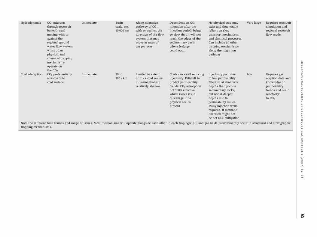
Hydrodynamic CO2 migrates
through reservoir
beneath seal,
moving with or
against the
regional ground
water flow system
whist other
physical and
chemical trapping
mechanisms
operate on
the CO2
Immediate Basin
scale, e.g.
10,000 km
Along migration
pathway of CO2
with or against the
direction of the flow
system that may
move at rates of
cm per year
Dependent on CO2
migration after the
injection period, being
so slow that it will not
reach the edges of the
sedimentary basin
where leakage
could occur
No physical trap may
exist and thus totally
reliant on slow
transport mechanism
and chemical processes.
Can include all other
trapping mechanisms
along the migration
pathway
Very large Requires reservoir
simulation and
regional reservoir
flow model
Coal adsorption CO2 preferentially
adsorbs onto
coal surface
Immediate 10 to
100 s km
Limited to extent
of thick coal seams
in basins that are
relatively shallow
Coals can swell reducing
injectivity. Difficult to
predict permeability
trends. CO2 adsorption
not 100% effective
which raises issue
of leakage if no
physical seal is
present
Injectivity poor due
to low permeability.
Effective at shallower
depths than porous
sedimentary rocks,
but not at deeper
depths due to
permeability issues.
Many injection wells
required. If methane
liberated might not
be net GHG mitigation
Low Requires gas
sorption data and
knowledge of
permeability
trends and coal ‘
reactivity’
to CO2
Note the different time frames and range of issues. Most mechanisms will operate alongside each other in each trap type. Oil and gas fields predominantly occur in structural and stratigraphic
trapping mechanisms.
in
te
rn
at
io
na
ljo
ur
na
lo
fg
re
en
ho
us
eg
as
co
nt
ro
l1
(2
00
7)
62
–6
86
5

i n t e r n a t i o n a l j o u r n a l o f g r e e n h o u s e g a s c o n t r o l 1 ( 2 0 0 7 ) 6 2 – 6 866
to discriminate between these two tiers of assessment. (Note:
Resources are those quantities of a commodity that are
estimated at a given time to exist within a jurisdiction or a
geographic area. Resources are of two types: discovered, or in-
place (i.e., existing commodity whose location and character-
istics are known, being assessed on the basis of scarce data),
and undiscovered, or inferred (i.e., not found yet but assumed to
exist based on inferences from geological knowledge and/or
various analyses). Reserves are those quantities of a com-
modity that are known to exist and that are commercially
recoverable. Their assessment integrates technical, economic,
environmental, societal and regulatory factors available at the
time of the assessment. Reserves are a subset of resources,
and usually accessibility, technology and economic cutoffs are
used to define and delineate reserves.)
Some of the contradictory estimates which are evident in
Fig. 1 are the result of using inappropriate methodology to
derive rough estimates. Many estimates use the surface area
of a sedimentary basin to serve as a guide as to the storage
potential of the basin. There is no reliable way to estimate or
provide a guide as to the resources contained within a basin
(including CO2 storage capacity) by using surface area, as is
documented for estimation of hydrocarbon resources around
the world (Bradshaw et al., 2005).
3. Trapping efficiency and timing
The efficiency of trapping for many of the mechanisms
described in Table 1 depends upon the migration rate of the
CO2, which itself is highly dependent on the rock and fluid
properties and geological characteristics of each site. The
conceptual geological settings that constitute the largest
potential storage volumes are (in decreasing potential
capacity) deep saline reservoirs, depleted gas reservoirs, oil
reservoirs (with and without enhanced oil recovery), and coal
beds. Trapping of CO2 in geological formations in the
subsurface can occur through various mechanisms. Esti-
mates of storage capacity must take into account the range of
trapping mechanisms that are possible at each site, the
different geological constraints on each mechanism, and the
fact that different trapping mechanisms operate on different
time scales that range from instantaneous to tens of
thousands of years. The complexity of these trapping
mechanisms and the variations that occur within them
individually and collectively demonstrate why simple capa-
city estimation methods will always have a range of
uncertainties. Furthermore, estimates of storage capacity
at specific sites may be highly sensitive to geological
parameters that are poorly known or even unknown (such
as relative permeability), requiring clear descriptions of
surrogate values used in calculations.
4. Resource pyramids
The concept of resource pyramids was advanced by McCabe
(McCabe, 1988) as a method to describe the accumulation
around the world of hydrocarbons in different categories. This
concept is proposed here to represent the similar issue of
capacity for CO2 storage in geological media. Because of the
multi-faceted aspects of this issue, three resource pyramids
have been proposed, representing (a) high level, (b) techno-
economic and (c) trap type and effectiveness aspects (Brad-
shaw et al., 2005).
4.1. High level resource pyramid
At the top of the high level resource pyramid (Bradshaw et al.,
2005) are all the storage sites with good geological character-
istics and that individually have large storage capacities,
which are located close by to emission sites with low costs of
capture. At the base of the pyramid are the extremely difficult
sites, with problematic geological conditions, small storage
capacity and that are located a great distance from sources
with large capture costs. However, the total potential storage
capacity of the sites at the base of the pyramid is very much
greater than those at the top. Contradictory capacity estimate
results have occurred when assessments do not adequately
define the boundary conditions and assumptions that have
been used, and so fail to describe their position on the resource
pyramid.
4.2. Techno-economic resource pyramid
Fig. 2 shows an example of a techno-economic resource
pyramid. When calculating capacity, several types of esti-
mates can and often are made, depending on the nature and
purpose of the assessment, and they all lie across different
regions of the resource pyramid. The following nomenclature
and definitions are a preliminary guide that should form the
basis of further work. This pyramid considers three technical
and economic categories, being theoretical, realistic and viable
capacity.
Theoretical capacity—assumes that the whole of a reservoir
formation is accessible to store free-phase CO2 in its pore
volume, or the whole of the formation water in a reservoir
formation is available to have CO2 dissolved into it at
maximum saturation, or the whole mass of coal is available
to adsorb and store CO2 at maximum adsorption capacity. This
provides a maximum upper limit to a capacity estimate,
however, it is an unrealistic number as in practice there
always will be technical and economic limitations across a
region that prevent parts of the reservoir formation from being
accessed and/or fully utilized. This represents the theoretical
limit of the whole geological system. It occupies the whole of
the resource pyramid.
Realistic capacity—applies a range of technical (geological
and engineering) cut-off limits to elements of an assessment
such as quality of the reservoir (e.g. permeability and porosity)
and seal, depth of burial, pressure and stress regimes, size of
the pore volume of the reservoir and trap, and whether there
may be other competing interests that could be compromised
by injection of CO2 (e.g. existing resources such as oil, gas, coal,
water, geothermal energy, minerals, national parks). This is a
much more pragmatic estimate that can be done with some
degree of precision, and gives important indications of
technical viability of CO2 storage. These estimates are within
the main body of the resource pyramid, but exclude the basal
parts of the resource pyramid.

Fig. 2 – Techno-economic resource pyramid for capacity for CO2 geological storage, showing the three levels of theoretical,
realistic and viable estimates. Theoretical includes the entire pyramid, realistic the top two portions and viable only the top
portion.
i n t e r n a t i o n a l j o u r n a l o f g r e e n h o u s e g a s c o n t r o l 1 ( 2 0 0 7 ) 6 2 – 6 8 67
Viable capacity—is the capacity arrived at by also consider-
ing economic, legal and regulatory barriers to CO2 geological
storage, and thus builds upon the realistic capacity assess-
ment. Detailed source/sink matching is performed at this
stage to match the best and nearest storage sites to large
emission sources. The source–sink matching should extend
beyond just geoscience and engineering aspects, and include
social and environmental aspects of locating storage sites.
Cost curves may also be derived and Monte Carlo simulations
performed to help estimate the level of uncertainty and upper
and lower ranges in the known and derived data versus the
actual data that become available once a project is imple-
mented. Once this level of assessment has been reached, it
may be possible at a regional level to express the capacity as an
annual sustainable rate of injection, not just as a total volume
(Bradshaw et al., 2004). These capacity estimates are at the top
of the resource pyramid.
4.3. Trap type and effectiveness resource pyramid
This version of the resource pyramid (Fig. 3) attempts to
represent the relationships between the reservoir quality and
trap types (left vertical axis), trapping mechanisms (bottom
axis) and the time that it takes until the trapping mechanism is
effective (right horizontal axis). The characteristics of the
trapping mechanisms are described in detail in Table 1. At
least three qualifiers need to be documented in this resource
pyramid to explain which storage capacity estimate method
has been used. At any time at a particular storage site, some of
these trapping mechanisms might be mutually exclusive (e.g.
dissolution into the fluids and displacement of fluids), whilst
others may partially act simultaneously (e.g. residual gas
saturation and compression of fluids and the rock matrix with
increasing pressure), and others will compete against each
other (e.g. simple compression of fluids such as occurs in a
closed system versus displacement of pore fluids in an open
system). Over the long term ‘‘geological’’ life of a storage site,
many of the trapping mechanisms may actually participate in
the eventual trapping process.
5. Effect of supply volume and injectivity onstorage capacity
As described for the techno-economic resource pyramid, there
is a need to clearly document whether storage capacity
estimates are based upon source to sink matching (viable
capacity), or whether injection sites are being considered in
isolation from economics and in isolation from the likely supply
volume (theoretical and realistic capacity). If the storage site is
not a clearly defined structural trap that is immediately
effective, and relies upon dissolution and residual trapping,
then the trap type and effectiveness resource pyramid needs to
be considered to conceptualise what capacity estimate method
is being described. If a site is of poor quality in terms of
permeability (and thus can only accept small rates of injection),
but has a lot of pore space and potential storage volume, then
there will be a limit to the rate at which the CO2 can be injected
for each well. This may limit its utility as a storage site because it
will require large capital costs for many wells and compressors,

Fig. 3 – Trap/reservoir quality (as a proportion of all reservoir volume), and effectiveness resource pyramid showing the
relationships between different trap and reservoir quality, trapping mechanisms and their effectiveness in terms of time
(years). The highlighted inset pyramid corresponds to the proportion of the total resource pyramid that relates to
dissolution trapping (see Table 1) that occurs along migration pathways over an effective time frame of up to 10,000 years.
i n t e r n a t i o n a l j o u r n a l o f g r e e n h o u s e g a s c o n t r o l 1 ( 2 0 0 7 ) 6 2 – 6 868
and, hence, quoting such a site as having large storage capacity
may be extremely misleading. As such, describing this capacity
by expressing it in terms similar to the documentation of
unconventional resources could help indicate that it might not
be an economically or technically efficient option, but future
changes in economics and technological advances could make
it viable.
6. Conclusions
Many of the contradictory assessments and errors in
calculated storage capacity are due to the desire or need to
make quick assessments with limited or no data. Such
assessments might have a place, but they should not be used
in setting forward looking strategy or for making investment
decisions, nor should they be released in the public domain
where they can be misunderstood and misused. Estimates
need to clearly state the limitations that existed (data, time,
knowledge) at the time of making the assessment and indicate
the purpose and future use to which the estimates should be
applied. Assessments that lack documentation of constraints
(or justification for their use) cannot be easily compared with
other assessments. A set of guidelines for estimation of
storage capacity will greatly assist future deliberations by
government and industry on the appropriateness of geological
storage of CO2 in different geological settings and political
jurisdictions.
r e f e r e n c e s
Bradshaw, J., Allinson, G., Bradshaw, B.E., Nguyen, V., Rigg, A.J.,Spencer, L., Wilson, P., 2004. Australia’s CO2 geologicalstorage potential and matching of emissions sources topotential sinks. Energy 29, 1623–1631.
Bradshaw, J., Bachu, S., Bonijoly, D., Burruss, R., Christensen,N.P., Mathiassen, O.M., 2005. Discussion paper on CO2
storage capacity estimation (Phase 1); a taskforce for reviewand development of standards with regards to storagecapacity measurement; CSLF-T-2005-9 15, August 2005, p.16. http://www.cslforum.org/documents/Taskforce_Storage_Capacity_Estimation_Version_2.pdf.
McCabe, P.J., 1988. Energy resources; cornucopia or emptybarrel? AAPG Bull. 82, 2110–2134.