co-axial connectors cambridge connectors
TRANSCRIPT

Co-axial Connectors Cambridge Connectors Page 1 Tel: +44 (0)1223 860041 Fax: +44 (0)1223 863625 Email: [email protected]
© Cambridge Electronic Industries Ltd. 2007

Co-axial Connectors Cambridge Connectors Page 2 Tel: +44 (0)1223 860041 Fax: +44 (0)1223 863625 Email: [email protected]
© Cambridge Electronic Industries Ltd. 2007
The Operation of Electrical Transmission Lines at High Frequency. It is important to understand that real 75 ohm connectors form only one component of a transmission line; other components to be considered include: wires, connectors, coaxial cables, dielectric slabs, PCB striplines and waveguides. At high frequency, such as in HD/SDI applications, it is critical that all of the components employed in the transmission line are impedance matched. Use of real 75 ohm connectors will not “convert” existing non impedance matched systems. The following guide gives an insight into parameters that must be considered when designing systems to operate at high frequency in an HD/SDI environment. Characteristics of transmission lines. Impedance is the resistance to the propagation of an alternating signal and is defined as the ratio of the complex voltage of a given wave to the complex current of the same wave at any point on the transmission line. Typical values for TV broadcast are 75 ohms. In HDTV/SDI applications, the approximations useful for calculations at lower frequencies are no longer accurate. Return Loss, is measured at the junction of a transmission line and a terminating impedance or other discontinuity, and is the ratio of the amplitude of the reflected wave to the amplitude of the incident wave. The return loss value describes the reduction in the amplitude of the reflected energy, as compared to the forward energy and is normally expressed -db. For all devices that are not perfect transmission lines, the return loss value varies with frequency. Insertion Loss is the decrease in transmitted signal power resulting from the insertion of a device in a transmission line. It is usually expressed relative to the signal power delivered to that same part before insertion. Insertion loss is usually expressed in decibels (dB). The insertion loss of a device may also be referred to as attenuation. Voltage standing wave ratio (VSWR) is the ratio of the voltage amplitude of a partial standing wave at an anti-node (max) to the voltage amplitude at an adjacent node (min) in an electrical transmission line. For example, the VSWR value 1.2:1 (often quoted as just 1.2) denotes maximum standing wave amplitude that is 1.2 times greater than the minimum standing wave value. Every discontinuity in the transmission line can have a negative effect on the integrity and final energy of the transmitted signal. It is therefore essential to ensure changes in impedance and geometry are reduced to a minimum. Connectors must be selected with consideration to a) the real connector impedance and b) the PCB termination method to avoid significant discontinuities. Connectors should have the same characteristic impedance as the system transmission line and have a VSWR as near to 1 as possible (or a return loss better than -20db) across the required frequency of operation. They should provide the necessary physical interface to the real world and should terminate to the PCB in a way that least disrupts the transmission path, (for instance PCB edge mounting connectors ensure the connector signal path is in the same plane as the PCB stripline). Cambridge Connectors real 75 ohm BNC connectors are designed to provide the physical and electrical characteristics that are essential for successful operation in HD/SDI environments. For a copy of our White Paper on selecting suitable components and optimising track layout and board geometry in HD/SDI applications please contact our application engineers on: Tel: 01223 860041 Fax: 01223 863625 Email: [email protected] Web site www.cambridgeconnectors.com

Co-axial Connectors Cambridge Connectors Page 3 Tel: +44 (0)1223 860041 Fax: +44 (0)1223 863625 Email: [email protected]
© Cambridge Electronic Industries Ltd. 2007
Real 75 ohm BNC Connectors for HDTV Serial Video Applications Introduction
High definition broadcast applications are pushing the operating parameters of interconnection products to the limit. To help meet these demands, Cambridge Connectors has designed a new range of Real 75 ohm BNC connectors which operate at the increased bandwidth and frequencies now required for HD Serial Digital Video environments. All are RoHS compliant. These Real 75 ohm connectors, which incorporate advanced geometry designs and specialised materials, include the following styles: edge card mounting; 2 part range for rapid board swap; low profile right angle version for high board densities; hybrid press fit for reduced production costs; top entry solder PCB mounting style. As a specialist supplier to the broadcast industry, Cambridge Connectors works in close partnership with its customers to produce interconnection solutions. In addition to standard product, Cambridge Connectors can also provide custom products to meet the specialised needs of its customers. For more details contact our applications engineers on. Tel: 01223 860041 Fax: 01223 863625 Email: [email protected] Web site www.cambridgeconnectors.com
Contents Introduction
Page 3
Two part design Page 4
Edge card mounting
Page 5
Slim line slotted nuts Page 5
Low profile Page 6 Press fit hybrid
Page 7
Top entry PCB mounting Page 8
Cable terminating BNC
Page 9
Return loss measurements Page 10
Cable terminated Real 75 ohm BNC connectors and patch leads. To complement these new products, Cambridge Connectors also produces Real 75 ohm BNC connectors and patch leads in either standard length or built to customer specification.

Co-axial Connectors Cambridge Connectors Page 4 Tel: +44 (0)1223 860041 Fax: +44 (0)1223 863625 Email: [email protected]
© Cambridge Electronic Industries Ltd. 2007
Real 75 Ohm BNC connectors for HDTV Broadcast Applications Two part design for rapid board swap Features • Real 75 Ohm BNC Connector • Designed for HD SDV applications • Two part construction for rapid board swap • PCB or front and rear bulkhead mounting • Circlip or threaded versions • RoHS Compliant • Real 75 ohm BNC patch leads also available General Description Two piece BNC female bulkhead, Real 75 ohm connectors, available in the following parts: -
Applications This two part 75 ohm BNC female connector range is specifically designed for the broadcast industry. It allows daughter boards in switch-ing and routing equipment to be swapped out without the necessity of removing attached patch cables; this greatly reduces downtime. The range includes: - PCB mounting; Rear and Front mounting bulkhead versions, secured by threaded nuts; and also a circlip bulkhead version. The PCB mounting “inner” is edge mounting to ensure Real 75 ohm performance. * Other materials such as Gold Plating are available to customer requirement. High definition broadcast applications - this Real 75 ohm BNC connector range, incorporates an innovative PCB edge mounting style. This provides a straight signal path along the connector, through the point of interface and onto the PCB track with minimal loss of transmission characteristics. For more details contact our applications engineers on. Tel: 01223 860041 Fax: 01223 863625 Email: [email protected] Web site www.cambridgeconnectors.com
Inner for 1.6 mm PCBs. XBT-1058-NGAY Outer for Circlip Bulkhead Mount 71X-0037-33 Inner for 2.4 mm PCBs XBT-1059-NGAY Outer for Threaded Rear Bulkhead Mount 71X-0038-33
Inner for 3.2 mm PCBs XBT-1060-NGAY Outer for Threaded Front Bulkhead Mount 71X-0039-33
Inner for top entry XBT-1061-NGAY Outer for PCB Mount 71X-0040-33 12 mm Circlip 71X-0036-00
Specification Electrical Impedance 75 Ohm Frequency Range 0 – 3.0 GHz Working Voltage 500 Vrms Dielectric Withstanding Voltage 1500 Vrms Reflection Factor (VSWR) 1.08 (Max) DC-1.5GHz
1.16 (Max) 1.5GHz-3.0GHz Contact Resistance Centre contact 1.5 m ohm
Outer contact 1.0 m ohm Insulation Resistance > 5000 Meg Ohm *Materials Centre Pin Phosphor Bronze / 10μ " Au Metal Parts Brass / Nickel Insulators Teflon®
Co-axial Connectors Cambridge Connectors Page 5 Tel: +44 (0)1223 860041 Fax: +44 (0)1223 863625 Email: [email protected]
© Cambridge Electronic Industries Ltd. 2007
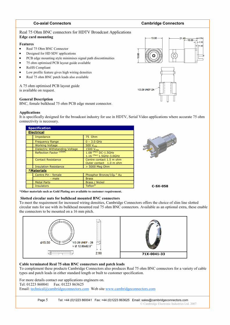
Real 75 Ohm BNC connectors for HDTV Broadcast Applications Edge card mounting
Features • Real 75 Ohm BNC Connector • Designed for HD SDV applications • PCB edge mounting style minimises signal path discontinuities • 75 ohm optimised PCB layout guide available • RoHS Compliant • Low profile feature gives high wiring densities • Real 75 ohm BNC patch leads also available A 75 ohm optimised PCB layout guide is available on request. General Description BNC, female bulkhead 75 ohm PCB edge mount connector. Applications It is specifically designed for the broadcast industry for use in HDTV, Serial Video applications where accurate 75 ohm connectivity is necessary. *Other materials such as Gold Plating are available to customer requirement.
Slotted circular nuts for bulkhead mounted BNC connectors To meet the requirement for increased wiring densities, Cambridge Connectors offers the choice of slim line slotted circular nuts for use with its bulkhead mounted real 75 ohm BNC connectors. Available as an optional extra, these enable the connectors to be mounted on a 16 mm pitch.
Cable terminated Real 75 ohm BNC connectors and patch leads To complement these products Cambridge Connectors also produces Real 75 ohm BNC connectors for a variety of cable types and patch leads in either standard length or built to customer specification.
For more details contact our applications engineers on. Tel: 01223 860041 Fax: 01223 863625 Email: [email protected] Web site www.cambridgeconnectors.com
Specification
Electrical Impedance 75 Ohm Frequency Range 0 – 3.0 GHz Working Voltage 500 Vrms Dielectric Withstanding Voltage 1500 Vrms Reflection Factor (VSWR) 1.08 (Max) DC-1.5GHz
1.16 (Max) 1.5GHz-3.0GHz Contact Resistance Centre contact 1.5 m ohm
Outer contact 1.0 m ohm Insulation Resistance > 5000 Meg Ohm *Materials Centre Pin - female Phosphor Bronze/10μ " Au
- male Brass Metal Parts Brass / Nickel Insulators Teflon® C-SX-058
71X-0041-33

Co-axial Connectors Cambridge Connectors Page 6 Tel: +44 (0)1223 860041 Fax: +44 (0)1223 863625 Email: [email protected]
© Cambridge Electronic Industries Ltd. 2007
Real 75 Ohm BNC connectors for HDTV Broadcast Applications Low profile (4mm centre) right angle PCB mounting Features • Real 75 Ohm BNC Connector • Designed for HD SDV applications • Low profile allows higher wiring densities • RoHS Compliant • Real 75 ohm BNC patch leads also available General Description BNC, female, low profile, right angle PCB mounting 75 ohm connector. Tailored geometry design coupled with judicious use of appropriate raw materials ensures that Real 75 ohm performance is achieved. Applications It is particularly suitable for the broadcast industry for use in HDTV, Serial Video applications where Real 75 ohm con-nectivity is essential. With a centre line of 4mm above the board, its low profile permits closer packing densities of daughter boards, which allows reduction in the bulk of routing and switching equipment.
Specification Electrical Impedance 75 Ohm Frequency Range 0 – 3.0 GHz Working Voltage 500 Vrms Dielectric Withstanding Voltage 1500 Vrms Reflection Factor (VSWR) 1.06 (Max) DC-1.5GHz
1.33 (Max) 1.5 GHz—3.0 GHz Contact Resistance Centre contact 1.5 m ohm
Outer contact 1.0 m ohm Insulation Resistance > 5000 Meg Ohm *Materials Centre Pin Phosphor Bronze / 10μ " Au Metal Parts Brass / Nickel Insulators TPX C-SX-069
* Other materials such as Gold Plating are available to customer requirement.
Return Loss Graph (measurements include PCB mounting)
Return loss @ 3.0 GHz -17.0 db max Return loss @ 1.5 GHz -31.0 db max For more details contact our applications engineers on: Tel: 01223 860041 Fax: 01223 863625

Co-axial Connectors Cambridge Connectors Page 7 Tel: +44 (0)1223 860041 Fax: +44 (0)1223 863625 Email: [email protected]
© Cambridge Electronic Industries Ltd. 2007
Real 75 Ohm BNC connectors for HDTV Broadcast Applications Top Entry PCB Mounting Press Fit Hybrid
Features • Real 75 Ohm BNC Connector • Designed for HD SDV applications • Hybrid design combines advantages of press fit and solder • Press fit techniques offer unequalled manufacturing economies • Solder centre contact ensures Real 75 ohm performance • RoHS Compliant Press fit manufacturing techniques allow large numbers of connectors to be pressed simultaneously into a PCB to form a secure electrical and physical bond. This offers considerable economies over traditional solder methods. To ex-ploit the advantages of press fit production methods in HD SDV applications Cambridge Connectors has, using radical internal geometry and specialised materials, developed a hybrid BNC product. This unique Real 75 ohm BNC connector can be pressed into the PCB in one operation to secure the outer contacts; a further solder operation then provides the Real 75 ohm bond with the centre contact. General Description Straight PCB mounting Real 75 ohm female press fit BNC connector. Applications It is specifically designed for the broadcast industry for use in HDTV, Serial Video applications where accurate 75 ohm connectivity is necessary and where press fit manufacturing processes are adopted. * Other materials such as Gold Plating are available to customer requirement. Cable terminated Real 75 ohm BNC connectors and patch leads To complement these products Cambridge Connectors also produces Real 75 ohm BNC connectors for a variety of cable types and patch leads in either standard length or built to customer specification. For more details contact our applications engineers on. Tel: 01223 860041 Fax: 01223 863625 Email: [email protected] Web site www.cambridgeconnectors.com
Specification
Electrical Impedance 75 Ohm Frequency Range 0 – 3.0 GHz Working Voltage 500 Vrms Dielectric Withstanding Voltage 1500 Vrms Reflection Factor (VSWR) 1.08 (Max) DC-1.5GHz
1.16 (Max) 1.5GHz-3.0GHz Contact Resistance Centre contact 1.5 m ohm
Outer contact 1.0 m ohm Insulation Resistance > 5000 Meg Ohm *Materials Centre Pin - female Phosphor Bronze/10μ " Au
Centre Pin - male Brass Metal Parts Brass / Nickel Insulators Teflon® C-SX-061

Co-axial Connectors Cambridge Connectors Page 8 Tel: +44 (0)1223 860041 Fax: +44 (0)1223 863625 Email: [email protected]
© Cambridge Electronic Industries Ltd. 2007
Specification
Electrical Impedance 75 Ohm Frequency Range 0 – 3.0 GHz Working Voltage 500 Vrms Dielectric Withstanding Voltage 1500 Vrms Reflection Factor (VSWR) 1.08 (Max) DC-1.5GHz
1.16 (Max) 1.5GHz-3.0GHz Contact Resistance Centre contact 1.5 m ohm
Outer contact 1.0 m ohm Insulation Resistance > 5000 Meg Ohm *Materials Centre Pin - female Phosphor Bronze/10μ " Au
Centre Pin - male Brass Metal Parts Brass / Nickel Insulators Teflon® C-SX-063
Real 75 Ohm BNC connectors for HDTV Broadcast Applications Top Entry PCB Mounting Features • Real 75 Ohm BNC Connector • Designed for HD SDV applications • RoHS Compliant • Real 75 ohm BNC patch leads also available General Description Straight PCB mounting Real 75 ohm female BNC connector. Although superficially similar to standard 75 ohm BNC products, enhanced internal geometry and the use of specialised materials produces a product with Real 75 ohm performance. Applications It is specifically designed for the broadcast industry for use in HDTV, Serial Video applications where accurate 75 ohm connectivity is necessary. * Other materials such as Gold Plating are available to customer requirement.. Cable terminated Real 75 ohm BNC connectors and patch leads To complement these products Cambridge Connectors also produces Real 75 ohm BNC connectors for a variety of cable types and patch leads in either standard length or built to customer specification. For more details contact our applications engineers on. Tel: 01223 860041 Fax: 01223 863625 Email: [email protected] Web site www.cambridgeconnectors.com

Co-axial Connectors Cambridge Connectors Page 9 Tel: +44 (0)1223 860041 Fax: +44 (0)1223 863625 Email: [email protected]
© Cambridge Electronic Industries Ltd. 2007
Real 75 ohm BNC Connectors for HDTV Serial Video Applications Crimp Cable Terminating Connector Features • Real 75 Ohm BNC Connector • Designed for HD SDV applications • Suitable for wide range of cable styles • RoHS Compliant • Real 75 ohm BNC patch leads also available General Description Straight crimp cable terminating Real 75 ohm BNC connector. Although superficially similar to standard 75 ohm BNC products, enhanced internal geometry and the use of specialised materials produces a product with Real 75 ohm per-formance. Applications It is specifically designed for the broadcast industry for use in HDTV, Serial Video applications where accurate 75 ohm connectivity is necessary *A wide range of 75 ohm cable types can be used including the following: Real 75 ohm BNC patch leads To complement these products Cambridge Connectors also produces Real 75 ohm BNC patch leads in either standard length or built to customer specification. For more details contact our applications engineers on. Tel: 01223 860041 Fax: 01223 863625 Email: [email protected] Web www.cambridgeconnectors.com
Specification
Electrical Impedance 75 Ohm Frequency Range 0 – 3.0 GHz Working Voltage 500 Vrms Dielectric Withstanding Voltage 1500 Vrms Reflection Factor (VSWR) 1.08 (Max) DC-1.5GHz
1.16 (Max) 1.5GHz-3.0GHz Contact Resistance Centre contact 1.5 m ohm
Outer contact 0.2 m ohm Insulation Resistance > 5000 Meg Ohm *Materials Centre Pin - male Brass
Metal Parts Brass / Nickel Insulators Teflon® Gasket Silicone Rubber Crimp Sleeve Annealed Copper XBT-1062-NGxx*
Cable type
*xx Cable Group
BT2002 AG BT2003 AR BT3002 AL PSF 1/2 AM PSF 1/3M AH RG59B/U AB RG140/U AB RG179B/U AF RG210/U AC S-02YCCY0.51/2.3 AP URM90 AB URM96 AC RG6 AS 2YCY AX

Co-axial Connectors Cambridge Connectors Page 10 Tel: +44 (0)1223 860041 Fax: +44 (0)1223 863625 Email: [email protected]
© Cambridge Electronic Industries Ltd. 2007
Real 75 ohm BNC Connectors for HDTV Serial Video Applications Return loss measurements. The following graphs demonstrate return losses throughout a 0.2 GHz to 4GHz frequency sweep.
Test Method The connector was reverse engineered using a 3D parametric modelling system. Reverse engineering the finished connectors ensured that the CAD models closely represented the manufactured product, (original design models assume perfect manufacturing techniques and processors).The models were then analysed within a state of the art high frequency electromagnetic field simulation system. In Real world applications both the PCB interface and the quality of the mating connector / cable can have a significant effect on the overall performance of the system. In order to provide meaningful engineering data, the simulation was set up with the source and load ports (near perfect 75 Ohm coaxial transmission lines) orientated longitudinally along the centre axis of the connector body, ensuring that the data generated was relevant to the DUT (Device under test) only. For more details contact our applications engineers on. Tel: 01223 860041 Fax: 01223 863625 Email: [email protected] Web site www.cambridgeconnectors.com
PCB mounting Real 75 ohm BNC connectors Edge card mounting BNC Two part BNC Top entry PCB mounting Press fit / solder hybrid PCB mounting BNC connector
Straight cable terminated Real 75 ohm BNC connector Unattached Terminated to cable and mating BNC connector