cng fuel system inspector study guide · cng fuel system inspector . study guide . sponsored by:...
TRANSCRIPT

CNG Fuel System Inspector
Study Guide
Sponsored by National Energy Technology LaboratoryUS Department of Energy DE-FC26-05NT42608
Contract Manager
Clean Vehicle Education Foundation
Point of Contact Doug Horne President 770-424-8575
FAX 770-424-8575 dbhornecleanvehicleorg
Submitted by
Acknowledgments It is a privilege to work on such a relevant and exciting effort as this Energy independence environmental and technology transfer issues are at the heart of a dynamic and mobile society and were at the heart of the project
Safety issues associated with the health and quality of the natural gas vehicle industry were the initial goals of the project But a slightly different perhaps more profound spirit emerged as we began our work We soon came to recognize a higher purpose to support and encourage a lsquomovementrsquo to participate in a larger mission improving an industry that can significantly impact our world This movement comprised individuals and companies loosely organized advocates officials technical experts and practitioners ndash each contributing a positive energy to help place alternative fuels higher on Americarsquos agenda
The material presented in this study guide could not have been collected without the cooperation of numerous alternative fuel industry representatives committees and individuals From these sources technical details and graphic examples were always forthcoming Time was freely given to review text or participate in development sessions
The funding to develop this material came from a grant from the US Department of Energy under the leadership of Mr Hank Seiff Technical Director for the Clean Vehicle Education Foundation
Additional support came from the United States standards development organization CSA America Inc Spearheading this effort was Mr Mike Dickerson Product Manager Personnel Certification With his patient guidance throughout the process we were able to complete a rigorous series of meetings and numerous conference calls culminating in a well developed examination and certification program for the CNG Fuel System Inspector
The following individuals and institutions contributed significantly to this text Clean Vehicle Education Foundation Mr Hank Seiff Long Beach Community College Mr Cal Macy Advanced Technology Training Centers Mr Peter Davis
To these and all of those who participated in this project thank you for your efforts and we hope you will find the result a contribution to your good work
William H lsquoBillrsquo McGlinchey AFV International Llc Lancaster OH (740) 205-2107 wmcglincheyattnet
2
About CSA America CSA America Inc is well known as the standards writing body in the United States for gas appliances and accessories and alternative energy products It had its origins in this country as the American Gas Association Labs Now they are part of CSA-International with laboratories all over the country The offices for this program are in Cleveland OH
CSA America Inc 8501 East Pleasant Valley Road
Cleveland OH 44131-5575 Tel (216) 524-4990 Fax (216) 520-8979
httpcsa-americaorg
In 2006 CSA America assumed the administration of the CNG Cylinder Inspector Certification program from CSA International with the goal of strengthening the content administration systems and procedures Since then CSA America has been working to update and improve the CNG Cylinder Inspector Certification program The new program was made available August 1 2008 as the CNG Fuel System Inspector Certification program and follows the International Organization for Standardization (ISO) 17024 Conformity Assessment standard the global benchmark for personnel certification programs
3
About the Exam The exam represents the conclusion of two years of development several workshops convened across the country and many more conference calls among a group of dedicated industry professionals The CNG Fuel System Inspector Certification is on a three year re-examination cycle Those CNG Cylinder Inspectors certified under the older version (prior to 812008) of the test will have to retest at the expiration of their CNG Cylinder Certification to re-certify in the expanded certification program In non-examination years there will be an annual administration fee to maintain your certification Unlike the previous program there will be no minimum cylinder or vehicle inspection requirements to meet in order to renew your CNG Fuel System Inspector Certification
The CSA test contains approximately sixty multiple choice questions There may be additional test questions included that are for evaluation purposes only and will not be part of the final scoring The questions are based on expert opinions from a cross section of the CNG industry after consideration of the skills and knowledge that a minimally qualified applicant should have They are taken in proportion to their importance from a carefully constructed set of objectives or tasks that inspectors would be expected to perform
In preparation for taking the exam you should first evaluate yourself against these objectives Honestly consider if you are confident that you know each specific task listed in the following Task List Note the percentage of questions you can expect in each category and check Yes (Y) or No (N) as you grade yourself This will form the basis for any additional study you need prior to taking the test
You can learn more about registration requirements fees qualifications and training resources from the CSA America website
httpcsa-americaorgpersonnel_certificationcng_certificationdefaultaspload=getcert
Appendix D has more about taking the test and a sampling of test questions for your review
Good luck and study hard
Bill
090129
4
2008 CSA Exam Objectives
SECTION 1 PREPARATION FOR INSPECTION 13 Y N
Objective 11 Assess Vehicle History
Knowledge 1 Know types of incidents that may cause damage that may not be detectable by inspection
Skills 1 Question the ownerfleet manager about the vehicle 2 Know how to search service records 3 Know how to check vehicle for collision damage fire etc 4 Search VIN number for accident related incidents
Objective 12 Identify potential high-pressure gas safety hazards
Knowledge
1 Know the dangers of cylinder rupture and component failure 2 Know how to assemble and disassemble system 3 Know the consequences of improperly secured PRD vent lines Skills 1 Listen for leaks 2 How to operate different types of valves Objective13 Employ proper cleaning and handling methods to prevent damage to the fuel system Knowledge 1 Know which types of cleaning solutions are appropriate for different materials
Skills 1 Demonstrate proper method for lifting and moving cylinders 2 Know which types and when to use certain cleaning tools Objective 14 Given a scenario identify the appropriate sequence of inspection steps Knowledge 1 Know what is required for an inspection 2 How to look up cylinder specifications 3 Know which steps are critical in sequence Skills
1 Organize a work plan and use a checklist
Objective 15 Demonstrate a familiarity with natural gas and its characteristics Knowledge 1 Know properties of Natural Gas (NG) Skills 1 Recognize NG odorant 2 Recognize when un-odorized NG is used
SECTION 2 DETERMINE INSPECTION REQUIREMENTS 9
Objective 21 Identify the cylinder manufacturer and the standard under which the cylinder was manufactured by looking at the label or serial number Knowledge 1 Know past and present cylinder manufacturing companies 2 Know the standard under which the cylinder was manufactured Skills 1 Familiarity with label layout difference between part numbers and serial numbers
6
Objective 22 Select the proper inspection standard andor the manufacturers inspection recommendations based on the label Knowledge 1 Familiarity with inspection standards
2 Know if there is a manufacturersrsquo standard thats applicable to the vehicle
3 Know that the manufacturersrsquo standard always goes first Skills 1 Ability to interpret the standards Objective 23 Determine which NFPA 52 requirements apply to the vehicle being inspected Knowledge 1 Know the dates of the past NFPA 52 revisions 2 Know how to recognize the labeling of an OEM certified vehicle vs an aftermarket conversion Skills 1 How to correlate the vehicle with NFPA 52 Objective 24 Verify that the cylinder inspection documents are appropriate to the vehicle Knowledge 1 Know the dates of the past inspection document revisions 2 Know how to recognize the labeling of an Original Equipment Manufacturer (OEM) certified vehicle vs an aftermarket conversion Skills
1 How to correlate your vehicle with the inspection documents
Objective 25 Know the sources of additional inspection information and explain where to find them Knowledge
1 Know the cylinder component system vehicle manufacturers Skills 1 Accessing contact information
7
SECTION 3 PRESSURE RELIEF DEVICE (PRD) INSPECTION 7
Objective 31 Given a scenario inspect PRD piping for damage obstructions restrictions and verify that it is properly seated to prevent foreign material from entering Knowledge 1 Know what a venting system looks like 2 Know function and appearance of venting systems 3 Know the different types of PRD channel configurations Skills 1 Recognize different types of damage 2 Recognize probable modifications Objective 32 Identify visible damage and assess serviceability of PRDrsquos and verify that the PRD has not been recalled Knowledge 1 Know how to recognize a PRD 2 Know the location of PRDs 3 Know lists of manufacturers Skills
1 Know how to find the list of recalled PRDrsquos
Objective 33 Recognize if the PRD vent line is properly routed supported and adequate for venting pressure Knowledge 1 Know what a good PRD looks like Skills
1 Be able to differentiate between original manufacturer versus later extrusion of the eutectic trigger
8
SECTION 40 PHYSICAL INSPECTION OF BRACKETS AND HIGH-PRESSURE COMPONENTS 18 Objective 41 Identify missing components or damage to guards and covers that could affect cylinder or system integrity Knowledge 1 Know in which situations guard covers are required 2 Know different designs of guards and covers Skills 1 Rubber gaskets and clearance requirements Objective 42 Assess the condition of CNG cylinder mounting systems
Knowledge
NA
Skills 1 Know how to identify systems that have been degraded 2 How to identify missing or out of place rubber isolation gaskets 3 How to identify over tightened brackets 3 How to identify misaligned brackets Objective 43 Identify CNG fuel system components and describe their functions Knowledge 1 Know the major components 2 Know the function of each component based on its appearance and location in the system Skills
1 Recognize defective damaged or missing components Objective 44 Recognize system defects that would require a partial or full system defueling
9
Knowledge 1 Know defects associated with system components 2 Know functions of system components
Skills 1 Recognize different degrees of component damage Objective 45 Verify that the CNG fuel system is free of natural gas leaks Knowledge 1 Know how to identify leaks by sound smell and sight 2 Know which leak-detection fluids are safe for use 3 Know that C-64 gives basic guidance of leak detection Skills 1 Proper use of leak-detection fluids equipment and methods
SECTION 5 PHYSICAL ASSESSMENT OF CYLINDERS 38
Objective 51 Classify the type of cylinder damage assess the level of cylinder damage and then determine the appropriate action Knowledge 1 Know types of damage 2 Know the three levels of damage 3 Know where to find the criteria to determine the level of damage Skills 1 Determine levels of damage
2 How to use a depth guage and tape measure Objective 52 List the cylinder label information
10
Knowledge
1 Know different types of labels
2 Know what is required on labels 3 Know different formats of labels Skills 1 Verify that the cylinder label is present and visible 2 Verify that the cylinder is marked for CNG use 3 Verify that the cylinder service life has not expired Objective 53 Recognize Level II or Level III damage that requires defueling for safety measures Knowledge
1 Know types of damage
2 Know Level II or III damage 3 Know where to find the criteria to determine the level of damage Skills 1 Determine levels of damage 2 How to use a depth gage and tape measure Objective 54 Select the proper measuring tool to assess the level of cylinder damage Knowledge 1 Know appropriate tools for appropriate uses Skills 1 How to read and calibrate the tools Objective 55 Determine when you need to consult the cylinder manufacturer to determine the level of damage Knowledge
NA
11
Skills 1 Applying standards to actual situations
Objective 56 Demonstrate familiarity with the concept of pressures and temperature relationships as applied to cylinder operating requirements Knowledge 1 Know temperaturepressure relationship 2 Know the service pressure may not be the fill pressure 3 Know maximum permissible fill pressure Skills 1 How to read pressure gages and thermometers Objective 57 Given a scenario recognize the different types of CNG cylinder materials and construction Knowledge 1 Know different types of cylinder materials 2 Know construction methods 3 Know how different materials respond to damage mechanisms Skills 1 Be able to recognize different cylinder materials and construction methods
SECTION 6 ORIGINAL CNG FUEL SYSTEM INSTALLATION 10
Objective 61 Determine that cylinders brackets components and shielding are installed to prevent damage and safety hazards
Knowledge 1 Know components applicable to NG systems 2 Know which components can be supported by piping 3 Know ground clearance requirements 4 Know acceptable locations for cylinders
12
5 Know acceptable mounting and bracketing 6 Know heat shielding requirements Skills
1 Recognize different types of components and their applications
Objective 62 Verify that the pressure ratings of the cylinder and all other labeled system components are equal to or greater than the vehicle pressure rating
Knowledge 1 Know how to determine the system pressure rating from the vehicle label 2 Know where to find and how to read pressure ratings on components Skills 1 How to determine if pressure reading from label matches component pressure ratings
Objective 63 Verify the existence location and operation of shut off valves as per NFPA 52 or the manufacturers specifications Knowledge 1 Know when shut off valves are required 2 Know where shut off valves are likely to be found Skills 1 Know appropriate way to test shut off valves 2 How hard to you twist the shut off valve handle before you stop Objective 64 Verify all required labels are installed and legible
Knowledge 1 Know which labels are required under the various codes 2 Know which parts of labels are required to be legible 3 Know where labels are to be mounted Skills 1 Understand the marking of the labels
13
SECTION 7 INSPECTION REPORTING 5 Objective 71 Know how and when to fill out all areas of applicable inspection forms Knowledge 1 Know which inspection form you need to use 2 Know to use the checklist during inspection Skills
1 Operate a digital camera
2 Know how to write a comprehensive description and recommendation Objective 72 Given an inspection scenario explain which actions you recommend Knowledge 1 Know the consequences of various defect levels 2 Know how to communicate to non-technical customers 3 Know sources for appropriate repair or replacement Skills 1 Communication with public vendors manufacturers
14
Table of Contents
Section 1 Preparation for Inspection Page 16
Section 2 Determine Inspection Requirements Page 18
Section 3 Pressure Relief Device (PRD) Inspection Page 23
Section 4 Physical Inspection of Brackets and High-Pressure Components Page 25
Section 5 Physical Assessment of Cylinders Page 27
Section 6 Original CNG Fuel System Installation Page 35
Section 7 Inspection Reporting Page 37
Appendix A Contact Information Page 38
Appendix B Sample Checklists Page 40
Appendix C Reference Resources Page 44
Appendix D Test TakingSample Questions Page 49
15
Section 1 Preparation for Inspection
Natural gas is arguably the safest cleanest and most economical transportation fuel available today While that is a rather bold statement it can be backed up by the facts As a CNG Fuel System Inspector you will be part of this growing movement toward alternative fuels whether your goal is contributing to a cleaner environment helping alleviate our dependence on foreign petroleum or reducing our national debt In order for this industry to flourish it must maintain the enviable safety history it has to date By joining the ranks of certified inspectors you can play a vital role in its development
Before any CNG fuel system inspection begins the inspector has quite a bit of work to do He or she must gather as much information about the vehicle history previous inspections any accidents etc as is available This can be done by interviewing the owner andor operators searching the existing service records and looking for any obvious signs of collision damage from accidents or more importantly vehicle fires
Inspection forms will require information on the vehicle VIN number as well as any additional identifiers the owner or agency may use eg license plate number Now is the time to obtain and record these (see Appendix B)
Just as with a pre-flight check of an airplane itrsquos prudent to do a General Inspection of the fuel system and cylinder installation A General Inspection is defined as an inspection for any signs of obvious or gross external damage sounds or smells of possible natural gas leaks or any other potential problems that might require immediate attention These inspections should also be included in any regular preventive maintenance programs or during any vehicle service or repair
Figure 11 Leak Testing
In the rare event that there would be an urgent safety concern the inspector should immediately decide on the appropriate action If leaks are found or more serious levels of damage are suspected stop and determine how to resolve the issue This can be something as simple as turning off a cylinder or fuel line shut off valve to recommending CNG defueling and contacting emergency responders before any further inspection is considered
More commonly the next step in preparing for an inspection is gaining access and cleaning all of the CNG fuel system components This can be done either by the owner or designated staff personnel or by the inspector Generally time and money can be saved if the owner of the vehicle performs this operation Regardless some care needs to be exercised Specifically cylinder coatings and components may be susceptible to caustic cleaning solvents Avoid soap solutions that contain ammonia as an example Often questions regarding the use of high pressure washing equipment arise Even if the cleaning solutions are appropriate care should be taken to avoid water intrusion into the PRD vent lines The cylinder manufacturer should be consulted first especially in the case of Type 4 composites Regular sponges wash rags etc are generally sufficient
16
Figure 12 Cleaning and Recording
Properties of Natural Gas
Natural gas as provided by Local Distribution Companies (LDCrsquos) or gas utilities has a distinctive odor Generally Ethyl Mercaptan is added to give a sulphur smell that allows detection at an early warning level since pure methane the major constituent of natural gas is odorless colorless and tasteless Any fuel has specific Upper and Lower Flammability Limits In the case of natural gas the lower limit is 5 by volume and the upper limit is 15 fuel to air The Mercaptan concentration is designed to be detectable at 20 of the lower flammability limit or at a 1 level fuel-to-air ratio well short of the point of possible combustion
It should be noted that Liquefied Natural Gas will not include the odorant and either on-board methane detectors will be added or a separate operation to reintroduce Mercaptan into the gas stream will be used
Other properties that make this fuel safer are
Natural gas is lighter than air The specific gravity of natural gas is 06 compared to air at 10 SG It will rise into the atmosphere if there is a leak and dissipate quickly
By comparison the flammability range for gasoline is 1 to 8 but remember that leaks from gasoline can accumulate and still be dangerous hours later while natural gas will have dissipated
To ignite natural gas the ignition source must be at least 1200deg F The ignition temperature of gasoline is 540deg - 800deg F or about half of what is required for natural gas
Below is a table of some of the important fuel characteristics
Table 11 (Courtesy General Motors)
17
Section 20 Determine Inspection Requirements
The United States has led the world in NGV technology particularly in the area of cylinder design and construction From their beginnings in the space industry lighter composite cylinders have become the lsquogold standardrsquo Several manufacturers have come and gone and as an inspector you should be familiar with them all Appendix A contains a list of most of the major companies past and present that have been a part of that history
There are four types of construction that are designated appropriately Type 1 thru Type 4
Types of CNG cylinders
Type Description load contained by metal
load contained by composite
NGV2-1 (Type 1) All metal cylinders either steel or aluminum
100 na
NGV2-2 (Type 2) Cylinders with metal liner and a hoop (center) wrapped composite
55 45
NGV2-3 (Type 3) Cylinders with thin metal liner and a fully wrapped composite
20 80
NGV2-4 (Type 4) Cylinders with a plastic liner and a fully wrapped composite
na 100
Beginning with Type 1 all steel or aluminum each subsequent type reflects efforts to reduce weight by replacing metal with lighter weight composite (fiberglass or carbon fibers in a plastic resin) materials The relative roles of metal and composites in the four designs can be understood by comparing the portion of the pressures retained by the liner and by the overwrap
In Type 1 all of the internal force is contained by the metal In Type 2 and 3 the metal and composite share the pressures The difference between the two is the coverage of the fiberglass overwrap Type 2 covers the center of the cylinder only while Type 3 wraps the entire cylinder Type 3 will have a significant decrease in the metal liner thickness
Figure 21 (Courtesy L DaShiell)
18
Figure 22 Type 2 Hoop Wrapped Figure 23 Type 3 Fully Wrapped
Type 4 is a full composite cylinder with no metal except for the end boss for the valve NOTE that without information from the manufacturerrsquos label you canrsquot easily tell the difference between a Type 3 and Type 4 cylinder
Not only must inspectors be knowledgeable about the cylinder companies in the industry (see Appendix A) but they must be intimately familiar with the various standards those companies manufactured to or under There is a priority to those standards as well
The first and foremost resource for any inspection is always the manufacturersrsquo guidelines In the absence of specific manufacturer specification the next two standards cover in a generic overview cylinder inspection and fuel system installation Those are the Compressed Gas Associationrsquos (CGA) document C-64 Methods for External Visual Inspection of Natural Gas Vehicle (NGV) Fuel Containers and Their Installations and the National Fire Protection Association (NFPA) 52 Vehicular Fuel Systems Code
Before any Detailed Inspection can begin the inspector must identify which of these standards applies There are currently two for CNG cylinders 1 ANSICSA NGV2 Compressed Natural Gas Vehicle Fuel Containers 2 DOTNHTSA FMVSS 304 Compressed Natural Gas Fuel Container Integrity (NOTE this is a US government standard referenced in 49 CFR 571304 Code of Federal Regulations)
These contain design qualification requirements that apply to manufacturers during production They outline the allowable materials along with manufacturing and quality control tests They are interesting to the inspector only for their rigor and as references
NGV2 is a voluntary industry driven standard that has been incorporated into the International ISO standard 11439 It details elaborate cycling burst impact environmental bonfire and rupture tests FMVSS 304 is a US government (DOT ndash National highway Traffic Safety Administration) Federal Motor Vehicle Safety Standard and as such does have the force of law They can be obtained on-line at ANSICSA NGV2 httpwebstoreansiorg or
wwwcsa-americaorg FMVSS 304 httpedocketaccessgpogovcfr_2003octqtrpdf49cfr571304pdf
They both specify periodic visual inspection of cylinders either every three years andor 36000 miles and after an accident or fire They are the basis for the visual inspection protocols used in the United States today
There were earlier standards from the Compressed Gas Association known as FRP-1 and FRPshy2 They were used by several cylinder manufacturers on a limited exemption basis by the Department of Transportation (see lsquoDOT-Ersquo in Fig 24) before the current standards were developed However these cylinders are generally beyond their useful life (15 yrs from the date [Mo-Yr] on the cylinder) and rarely seen
19
Cylinder labels can help determine the standards for a particular cylinder Note the NGV2 DOT or DOT-E designations in the following examples
Figure 24 (Courtesy GTI)
Labels are also required to give critical information regarding the cylinder manufacturer the service pressure serial andor model numbers and the container build date and expiration date
CGA C-64 deals primarily with cylinder inspection whereas NFPA 52 deals with the rest of the fuel system installation There are overlaps in both but this is generally the distinction between the two As with any standard they are dated and undergo periodic revisions Each edition will generally have a history of the previous revisions or indication of the changes listed in the introductions Inspectors should be aware of the changes and keep current on the standards
This raises a common question when dealing with older vehicles Which version should I use the latest edition or the one that was in effect when the vehicle was produced The best advice is to always follow the most current guidelines and if there are discrepancies use good judgment on whether they create a serious safety concern and finally err on the side of caution Where a system is built to an earlier standard and not required to be updated to a later version it should not be faulted for not meeting the later standard unless there is an obvious safety issue
20
This issue comes up more with revisions to NFPA 52 and the installations of downstream components Inspectors should be familiar with these as well The major components of any NGV fuel system will consist of most if not all of the following
bull Fill receptacle bull One-way check valve(s) bull Fuel storage cylinder(s) bull Cylinder shut-off valve bull Pressure relief device (PRD) bull Manual lsquoQuarter-Turnrsquo shut-off valve
bull Annealed stainless steel fuel tubing bull Shut-off valves (Lock-offs) bull Pressure regulator(s) bull Mixer assemblies (older vehicles) bull Gas injectors
Figure 25 Typical Fuel System Components (Courtesy LBCC)
21
In conclusion these standards the manufacturersrsquo specifications CGA C-64 and NFPA 52 (in that order) form the basis of the Detailed Visual Inspection protocol A Detailed Visual Inspection performed by trained certified personnel is the subject of this study guide
The Clean Vehicle Education Foundation (CVEF) has made available a CD containing all of the manufacturersrsquo specifications they were able to obtain A copy can be obtained from CSA or CVEFrsquos John Lapetz at jlapetzcleanvehicleorg)
22
Section 30 Pressure Relief Device (PRD) Inspection
Safety factors on NGV fuel systems are stringent Cylinders are designed to withstand at least 225 times the working pressure All of the downstream components are safe at three times their working pressures (The battery of tests that cylinders have to pass in order to be certified can be found in the NGV2 standard) The device that assures cylinders will lsquorelieversquo pressure in a fire is the Pressure Relief Device (PRD)
Pressure Relief Devices have a checkered history Early versions had high failure rates and several were subject to recall Today new designs and improved manufacturing have all but eliminated these problems The job of these devices is to relieve pressure from NGV cylinders in the event of a fire that could lead to a cylinder rupture Standards do not require PRDrsquos to vent during overpressurization of a cylinder (CNG fuel dispensers are relied on to control pressure) but they are required to vent during a vehicle fire
There are many combinations of temperature and pressure mechanisms used in PRDs but two basic types are in wide use for compressed natural gas today
Thermally Activated This design is built to protect gas-containing vessels from rupture in case of fire One style uses an alloy called a eutectic with a specific melting point as an integral part of the PRD seal and a newer type that relies on the eutectic material only as a thermal triggering method
Figure 31 (Courtesy Circle Seal Controls) Figure 32 (Mirada- Courtesy L DaShiell)
Series Combination
This type has a thin steel lsquorupturersquo or lsquoburst discrsquo designed to burst at a predetermined pressure backed by a lead eutectic as a plug or thru a series of channels within a brass body It requires excessive pressure and temperature to cause it to operate It cannot prevent an improperly filled (overfilled) cylinder from rupturing due to hydrostatic pressure at room temperature or any temperature below the melting point of the fusible material Both the burst pressure and temperature are generally stamped on the PRD body
Figure 33 Series PRD
23
There are two conditions aside from mechanical damage with PRDrsquos that an inspector must look for namely leakage and premature extrusion of the eutectic The first requires some form of leak testing and in the case of attached vent lines may present some challenges to access or assure that the PRD is OK
By the same token evaluating an extruded eutectic can be difficult Consider these three Pressure Relief Devices It would appear that the lead plug on the right has begun to extrude but the center and right PRDrsquos are both new So the difference between a manufacturing anomaly and an actual extruded eutectic might not be obvious You must see evidence of damage or leaking of the fusible material before condemning it
Figure 34 PRD
Mechanical damage can occur when moisture is allowed to collect at the PRD During freezing weather cases have been reported where the PRD released even though there was no indication of fire NFPA 52 requires the venting system prevent water dirt or any foreign objects from collecting in the vent lines or PRD (see Section 64 NFPA 52 2006)
This is the biggest cause of PRD failure and many designs overlook this Check for evidence of water intrusion bull Loose or stretched PRDrsquos bull Loose fittings on the outlet side bull Leaks bull Water marks (soap scum lime etc) in the vent tube or the PRD bull Evidence of reverse pressure on the PRD (more pressure in the outlet than in the tank)
[Ice can generate over 10000 psi] NOTE Rubber caps that have been knocked off particularly by cleaning brushes or tree branches can cause this bull Rubber caps that break down in UV bull Lack of caps or drain holes bull Vent tubes that run straight up They should have a bend so that any water that does accumulate
doesnrsquot fill the PRD bull Caps that are to tight that allow the inevitable permeation of gas through the PRD causes a
pressure build-up that blows off the cap Caps should have the ability to vent the tiny flow may come through the PRD
24
Section 40 Inspection of Brackets and High-Pressure Components
Inspection of cylinder mounting assemblies is the second largest portion of the certification exam This section along with Section 6 dealing with the rest of the system components comprises 28 of the questions
NFPA 52 is the primary resource for requirements on the installation of NGV Fuel Systems The current edition (2006) devotes the entire Chapter 6 to Installation of cylinders venting systems piping and valves pressure gauges fill receptacles and regulators The inspector should be familiar with all of them What follows is a summary (not intended to be complete) of the major points
Beginning with cylinders
bull May be located within below or above the passenger compartment bull No portion can be located ahead of the front axle or behind the point of attachment of
the rear bumper bull Must have the label visible bull Cannot be within eight inches of the exhaust system without proper shielding bull Must be mounted at least nine inches above the ground for vehicles over 127rdquo wheel
base or at least seven inches for vehicles with 127rdquo or less measured with the tires deflated
bull Be capable of restraining the cylinder when subjected to a force of eight times the weight of the cylinder in six principle directions without moving over one half inch
Figure 41 Six principle directions
bull Incorporate manufacturerrsquos recommended brackets with rubber gaskets and torque to specification
bull Be properly shielded from sunlight cargo or road debris
Figure 42a Bad Mounting Figure 42b No Shielding
25
bull Cylinder valves and fittings mounted in the passenger compartment must be properly vented to the outside using tubing or a vapor barrier
bull Rubber gaskets shall be installed under the clamping bands to provide insulation between the bands and the containers
bull Must not adversely affect the driving characteristics of the vehicle
Venting systems included here can refer either to high pressure PRD vent lines or low pressure lsquovent bagsrsquo for the neck of the cylinder and all fittings within the passenger compartment (The trunk is considered part of the passenger compartment)
bull All potential leak points must be protected (cylinder valves and fittings) bull High pressure PRD vent line must be metallic and electrically conductive bull Cannot vent into a wheel well bull Must prevent water dirt or other contaminants from collecting in the lines or PRD bull The PRD and cylinder must be in the same vehicle compartment bull Low pressure enclosures must be gastight made of low-density polyethylene or
equivalent free of tears bull Vent lines must be adequately secured have a burst pressure at least 1 frac12 times the
pressure of an activated PRD and capable of withstanding 1120degF for 20 minutes
Figure 43 Polyethylene vent bag (L DaShiell) Figure 44 Formed vent cover (L DaShiell)
26
Section 50 Physical Assessment of Cylinders
This section provides the inspector with a description of some types of damage that can occur with CNG cylinders As it is not possible to address every possible damage scenario these are the most common These guidelines are defined in specific detail in the Compressed Gas Associationsrsquo C-64 document This is also the largest portion of the exam ndash 38
The cylinder manufacturerrsquos recommendations (if available) always take precedence and are the primary source for information
CGA C-64 lists general guidelines CNG cylinder damage is classified in three levels The levels are as follows
Level 1 mdash any scratch gouge or abrasion with a damage depth of less than or equal to 010 inch Level 1 damage is acceptable and does not need to be repaired Refer to CGA C-64 as a guideline for each type of damage and the allowable limits Some manufacturers allow different limits over 010 inch for newer tanks Always consult the manufacturer of the cylinder if damage exceeds 010 inch for their exact requirements
Level 2 mdash any scratch gouge or abrasion with a damage depth of 011 to 050 inch Level 2 damage requires rework (either in the field or by the manufacturer) a more thorough evaluation or destruction of the cylinder depending on severity
Level 3 mdash any scratch gouge or abrasion with a damage depth greater than 050 inch Level 3 damage is severe enough that the cylinder cannot be repaired and must be destroyed All fire and chemical damage is Level 3 if it does not wash off
Level 1 cut or abrasion damage is generally 010 inch or less according to CGA C-64 However the manufacturer is the final authority having jurisdiction over damage levels Some Level 2 damage may be repaired in the field depending upon manufacturerrsquos guidelines and procedures Between Level 2 and Level 3 there are acceptable field repairs available to resolve some conditions to a level where they can be resolved to Level 1 and returned to service There is also Level 2 damage criteria where the manufacturer has to complete the repair but the cylinder can be re-certified and returned to service Depending upon the type of cylinder and the manufacturer the point at which damage becomes Level 3 varies Some like Dynetek Type 3 cylinders allow rework by the manufacturer for cuts from 030 to 050 inch damage Some Type 4 cylinders such as the Tuffshell by Lincoln Composites allow rework by the factory for scratch gouge or abrasion damage from 036 to 050 inch and condemn the cylinder after 050 inch The area where the damage occurs can alter the allowances eg the radius of the dome When in doubt check the manufacturerrsquos specific tolerances
NOTE Although Level 1 damage does not require rework all damage must be recorded
27
Damage Types
1 Surface Corrosion or Pitting This is most prominent on Type 1 and 2 cylinders due to exposed metals Many newer cylinders have epoxy painted coatings to help prevent this damage Corrosion should be cleaned off evaluated and resealed to prevent further damage Corrosion or pitting over 030 inch in depth can be Level 3 damage if it covers considerable surface areas of the cylinder (see sect7614 of CGA C-64) Type 1 cylinders must be evaluated for loss of wall thickness This will require specifics on the original cylinder CGA C-6 provides additional guidance and lists wall thicknesses for certain steel cylinders
Figure 51 Corrosion
2 Fatigue or Stress Corrosion Cracking This occurs when the cylinder is cycled repeatedly causing expansion and contraction of the cylinder which is usually a sign of age or over pressurization The fiber wrap cracks longitudinally causing loss of the cylinder pressure safety factor Any identified stress or fatigue cracking is Level 3 damage A contributing factor can be chemical attack eg battery acid
Figure 52 Stress Corrosion Cracking (SCC)
3 Scuffing or Abrasion Damage This is very common on cylinders that are mounted underneath the vehicle if shielding is inadequate or the cylinder is exposed Type 2 3 and 4 cylinders with less than 0 010 in have Level 1 damage
28
Figure 53 Abrasion Damage
4 Surface Cuts and Scratches These are caused by a foreign object coming in contact with the cylinder Brackets and other items rubbing against the cylinder can also cause this damage Cuts or gouges less than 0010 in deep are defined as Level 1 damage regardless of length number or direction Cuts or scratches greater than or equal to 0010 in deep are defined as Level 2 or Level 3 damage and may require the use of manufacturerrsquos guidelines (see sect752 of C-64)
Figure 54 Cuts
5 Blunt or Sharp Object Impact Damage Minor dents up to 116rdquo inch and greater than 2 in diameter on Type 1 cylinders can be tolerated However blunt impact damage on Type 2 3 and 4 cylinders is very hard to evaluate and can be dangerous especially on Type 4 cylinders Extreme care must be taken to determine if any deformation of the cylinder is present indicting fiber damage This is a sign that the cylinder may not be structurally sound and is considered Level 2 or 3 damage
29
Figure 55 Impact damage
6 Collision Fire or Heat Damage Any indication that the vehicle has been involved in an accident or fire requires careful examination of the cylinders Follow the manufacturerrsquos guidelines for such damage Generally if Type 2 3 or 4 cylinders are exposed to excessive heat or any discoloration occurs that does not wash off it is considered Level 3 damage
Figure 56 Heat damage
7 Chemical Attack Acids and other chemicals can severely damage the cylinder wrap and possibly the metal itself Extreme care should be taken to identify and neutralize any chemicals spilled on the cylinder Only minor discoloration is allowed after neutralization and a very careful inspection should be performed to make sure the chemical did not get between the wrap and the cylinder where unseen damage could progress Chemical attack can also lead to Stress Corrosion Cracking (see No2 above) Comdyne cylinders suspected of being exposed to acid should be depressurized as soon as possible to prevent rupture The cylinders should then be removed from service rendered unusable and disposed of Any other CNG cylinder that has been exposed to acid should be examined in accordance with either the vehicle or cylinder manufacturerrsquos recommendations Ref CVEF Safety Advisory
30
Figure 57 Chemical damage
8 Bulging Bowing of Cylinder Wall All visible outward bulges indicate a problem with the cylinder material and should be considered Level 3 damage (sect762 CGA C-64) This is most prominent on Type 1 and the exposed surfaces of Type 2 cylinders
9 WeatheringUV Damage Ultraviolet light can cause damage to the wrap which must be addressed In most cases the manufacturers have coatings on the cylinder to prevent this damage Excessive weathering results in Level 3 damage as the fibers are damaged
Figure 58 UV damage
10 Over-Pressurization Leaks Any cylinder that leaks or has been exposed to over 125 times its service pressure is to be considered to have Level 3 damage Bubbles on the surface of Type 4 cylinders may be indications of leaking of the liner and could be Level 3 damage Further tests to determine if it is trapped air between the liner and the overwrap or is in fact leaking gas should be performed
31
11 Labeling
A label that cannot be seen requires repair and if it is missing or illegible it becomes Level 3 damage
It should be noted that in addition to the cylinder label OEM manufacturers or after-market conversions must also have a label (usually located in the engine compartment) that identifies the vehicle as being CNG-fueled and includes service pressure the installers name or company the cylinder retest or expiration date and the total container(s) water volume in gallons or liters
According to NFPA 52 another label is required at the fill connection receptacle that specifies CNG the system working pressure and the cylinder retest or expiration date Most OEMrsquos also follow this recommendation
All the following are to be considered Level 3 damage bull A missing cylinder label bull All fire damage if it leaves discoloration bull All chemical damage if it leaves discoloration bull Any noticeable discoloration that cannot be washed off bull Stress corrosion cracking bull Impact damage on Type 4 cylinders
32
The following table reprinted from CGA-64 by permission gives a detailed breakdown of generic cylinder damage limits
Condition Level 1 Level 2 Level 3 C-64 ref
Composite and metal containers (All container types)
Labeling Legible and clean Required information all legible Information correlates with vehicle service
Only manufacturer and serial number is clear Other required information is illegible 1
Serial number illegible or untraceable or unidentified manufacturer or modelpart number Beyond service life
79
Cutsscratchesgouges lt001 in (025 mm) 2 ge001 (025mm) deep2 752
Charringsooting None Washes off2 Permanent marking 753
Gas leakage None Bubble test negative Bubble test confirms leak 754
Chemical attack Cleans off No residue or affect Chemical is know not to affect container type
Discoloration is minor after cleaning no material loss2
Permanent discoloration lossdisruption of material1
755
Weathering (UV effects) None Coating disruption andor loss2
Excessive Look for other condition effects
756
Involved in a collision accident or fire Container subjected to high or unknown heat
No indications and vehicle owner know of no accident fire or heat exposure
Owner reports vehicle was in a fire accident or exposed to heat1
Indications of vehicle anor container impact or heat damage1
7
72
753
Overpressurization No indication or knowledge by inspector
Cylinder reported to have been pressurized above the applicable design standard
75
Composite containers (Type 23 and 4)
Impact None Dents fiber breaking cuts etc1
Permanent deformation of container1
772
Stress corrosion cracking None Questionable or unsure1 Any identified SCC 75
Abrasion lt0010 in (025 mm) deep 2 3 ge001 in (025 mm) deep 771
Metal containers (Type 1 and the exposed metallic portions of Type 2)
Bulgingbowing None or shape can be identified as lsquobananarsquo or bower (Type 1 containers only)
All visible bulges are Level 3 damage See 1 for questionable bow
Visible bulge or bowed shape interferes with proper mounting
762
Corrosion pits lt0035 in (0889 mm) deep 1 ge0035 in (0889 mm) deep 7611
Corrosion line pits lt003 in (076 mm) deep 1 ge003 in (076 mm) deep Any depth over 6 in long (152 cm)
7614
Dents None Minor dent(s)1 lein (51 mm) diameter or ge00625 in (1588 mm) deep
763
Abrasions None Minor Depths that reduces wall thickness below minimum allowable
764
1 Contact container manufacturer for criteria and procedure(s) or get the needed information from product literature instruction manual(s) written recommendations advertisements etc
2 Specified by manufacturer Repair may be possible if directed by container manufacturer
3 Exposed fibers may be coated Contact manufacturer 33
Measuring Damage Measuring damage is very difficult with the normal differences in the cylinder wrap thickness Cuts tend to have a flared edge to them which makes them also stick up on the edges A depth gauge or dial caliper that has been sharpened to a point is needed to accurately measure the damage while bridging the gap accurately
Sometimes it is necessary to use a straight edge across a gouge to seek a level from which to measure With this method you must subtract the thickness of the straight edge from your reading
Figure 510
34
Section 60 Original Fuel System Installation
This section deals with the rest of the fuel system components It includes fuel lines valves fittings pressure regulators and filling receptacles Beyond the first stage or high-pressure regulator systems diverge in their approach and technologies As such there will not be any questions on underhood fuel mixing strategies either mechanical or computer controlled
Again NFPA 52 is the primary resource for the installation of NGV Fuel Systems What follows is a summary (not intended to be complete) of the major points The latest edition should always be consulted for more detail NOTE NFPA 52 is designed as a minimum guideline for aftermarket conversions The OEMrsquos however build to a different set of standards that may go beyond the requirements of aftermarket converters
Fuel lines (piping) considerations bull When passing through a panel shall be protected by grommets or the equivalent bull Shall be mounted or supported to minimize vibrations and breakage due to strain or
wear (This suggests stress loops or vibration loops between moving parts)
bull Fittings or joints should be located in accessible positions
Installation of valves bull Every cylinder must have a manual or normally closed automatically-actuated (eg
electric) shutoff valve bull Every cylinder on an on-road vehicle must have a second valve either manual or
automatically actuated that allows isolation of the cylinders from the rest of the fuel system
Figure 61 Manual and Electric Shut off Valves
bull If a manual shutoff valve is used it must not require more that 90 degrees rotation (quarter turn valve) to close4
bull Access to the manual shutoff valve shall not require the use of any tool or key bull The lsquoquarter turnrsquo valve must be indicated with a label or decal bull A final valve that automatically prevents the flow of gas to the engine when the engine
is not running even with the key on is also required NOTE electronic fuel injectors meet this requirement
bull Valves must be securely mounted and protected bull The fuel system must have a backflow check valve between the cylinders and the fill
receptacle This is incorporated into the NGV1 fill receptacle
4 In the case of shutoff valves this has caused confusion in that most OEM Natural Gas Vehicles do NOT require an additional manual or quarter turn shutoff valve beyond the cylinders The OEMrsquos however build to a different set of standards that go well beyond the requirements of aftermarket converters
35
bull The check valve mounting must be able to withstand the breakaway force (150 lbs) of the fill hose
bull There must be an additional check valve located between the cylinders and the fill point
Pressure gauges
While pressure gauges are optional they do serve to give technicians the best information on system status before any service is performed If used they
bull Cannot allow gas into the passenger compartment bull Must be equipped with shatterproof lens and an internal pressure relief bull Must have a limiting orifice (that reduces dial fluctuation) bull Shall be securely mounted and shielded
Pressure Regulators bull Must have a means to prevent refrigeration effects bull Must be installed so that their weight is not placed on the attached gas lines
Fueling Connections bull Fueling receptacles must be mounted to withstand a breakaway force beyond that
specified for the dispenser hose (currently 150 lbs) bull Must have clearance around the fueling connection to prevent interference with the
fueling nozzle
Early in the development of the NGV industry several different fill connection profiles were used Adapters were used to switch between them These are no longer allowed Today they have all been replaced by the current industry standard known as NGV1 This applies to fill nozzles on dispenser hoses and receptacles on vehicles The design allows for three different fill pressures still found around the country 2400 psi 3000 psi and 3600 psi The connector on the fill hose is usually color coded to reflect these pressures Green 2400
Blue 3000 Yellow 3600 The unique feature is that you can always connect a lower pressure hose to a higher pressure fuel system but you canrsquot hook a higher pressure hose to a lower pressure system
36
Section 70 Inspection Reporting
Proper documentation communication and reporting are the final steps in the process The ability to convey your findings to both owners and agencies will impact both them and the industry
Several checklists are available as guidelines for a complete inspection (See Appendix B) These are primarily for the benefit of the owner of the vehicle not to report findings to the certifying agency or any other entity However the inspector should retain a copy for his or her records as a matter of due diligence They all include details of the vehicle an itemized list of inspection criteria and areas to record your results
At the present time CSA America is NOT requiring that copies of the inspection form be sent to them at the completion of the inspection But customers will want a copy as evidence of your work Beyond the written form and results many owners appreciate a photo attachment of the system condition This can aid in the description of any damage and serve as a benchmark at the time of the examination Digital photographs and electronic files can easily be added to the reports
The last question that may arise is how to handle disposition of cylinders or systems that have potentially serious damage that would require immediate action There are two situations where cylinders would need to be defueled or depressurized - scheduled or intended defueling such as removal or return of a out-of-date cylinder and emergency defueling in the case of confirmed or suspected Level 3 cylinder damage
The use of atmospheric venting must be done with care A static electrical charge can build up when releasing gas that can cause a spontaneous ignition There are several documents that cover the necessary precautions to prevent this including CGA C-64 Appendix C NFPA 52 Section 614 (2006) and the GTI Cylinder Care and Maintenance Handbook All indicate that this should be done only by trained personnel Atmospheric defueling should only be done with approval of local authorities as natural gas (methane) is a potent greenhouse gas
Figure 71 Intended defueling
Cylinder defueling is not the responsibility of the fuel system inspector however your advice may be helpful in guiding the authorities having jurisdiction in the proper procedures CGA P-22 details the disposition of compressed gases and their containers It recommends necessary training handling decommissioning (including removing all identifying marks) purging and rendering the cylinder unusable by drilling or cutting one or two half inch diameter holes Also see CGA C-64 Appendix C for an additional sample procedure
CAUTION Certain Type 4 plastic-lined cylinders may be sensitive to rapid defueling Consult the cylinder manufacturer for guidance PARTICULAR ATTENTION should be paid to defueling cylinders with internal electronic solenoid valves Always follow the manufacturersrsquo instructions
37
Appendix A
Cylinder Manufacturers
CNG Cylinder Corp In a letter dated September 14 2006 CNG Cylinder Corp DOT-Exemptions have been granted to SCI Pomona CA See SCI below for contact information
Comdyne Comdyne Cylinder Co is no longer in business See CVEF Safety Warning dated Nov 6 2007 (httpwwwcleanvehicleorgtechnologyComdyne_Warningpdf)
Dynetex Industries 4410 46th Ave SE Calgary Alberta Canada T2B 3N7 Tel 888-396-3835 httpwwwdynetekcomcngphp
Faber Industrie SpA Zona Industriale 33043 Cividale del Friuli (Udine) - Italy httpwwwfaber-italycomcnghtm
Lincoln Composites 4300 Industrial Avenue Lincoln NE 68504 Tel 800-279-8265 httpwwwlincolncompositescom
Lucas Aerospace Power Equipment Co is no longer in the CNG cylinder business That division has changed hands several times including TRW and AeroVantix Some information can be obtained from the Clean Vehicle Education Foundation
Luxfer Gas Cylinders USA 3016 Kansas Avenue Riverside California 92507 USA Tel +1 951 684 5110 or 1-800-764-0366 httpwwwluxfercylinderscomproductscng
NGV Systems Inc is no longer in business however information can be obtained from SCI
PST (Pressed Steel Tank Company Inc) Tel 414-476-0500 httpwwwpressedsteelcomindexhtml No longer producing CNG cylinders but information is still available
Quantum Fuel Systems Technologies 17872 Cartwright Road Irvine CA 92614 Tel 949-399-4500 httpwwwqtwwcom
SCI (Structural Composites Industries) 325 Enterprise Place Pomona CA 91769 Tel 909-594-7777 httpwwwscicompositescom
38
Taylor-Wharton-Cylinders 521 Green Cove Road Huntsville AL 35803-3033 Tel +1-256-650-9100 or 800-898-2657 httpwwwtaylorwhartoncom
OEM Manufacturers Blue Bird Tel 912-822-2091 httpwwwblue-birdcom Daimler Chrysler Tel 248-576-4117 httpwwwdcbusnacom El Dorado National Tel 909-591-9557 httpwwwenconlinecom Ford Tel 313-322-4771 httpwwwfordcom Freightliner Tel 503-745-5219 httpwwwfreightlinertruckscom GM Tel 905-644-5020 httpwwwgmcom Honda Tel 310-781-5718 httpwwwhondacom NABI Tel 256-831-6155 httpwwwnabiusacom New Flyer Tel 402-464-6611 httpwwwnewflyercom Orion Tel 905-403-1111 httpwwworionbuscom Thomas Built Buses Tel 336-881-7243 httpwwwthomasbuscom
Equipment ManufacturesConverters BAF Tel 2142311450 httpwwwBAFtechnologiescom Baytech Tel 415-949-1976 httpwwwbaytechcorpcom Campbell-Parnell USA Tel 623-581-8335 httpwwwusealtfuelscom ECO Fuel Systems Tel 604-888-8384 httpwwwecofuelcom FAB Industries Tel 2568316155 httpwwwfabindcom TeleflexGFI Tel 519-576-4270 httpwwwteleflexgficom ITT Conoflow Tel 843-563-9281 httpwwwconoflowcom NaturalDrive Tel 801-768-2986 httpwwwnaturaldrivecom Parker Tel 256-881-2040 http wwwparkercom Sherwood Valves Tel 724-225-8000 httpwwwsherwoodvalvecom SSP Fittings Tel 330-425-4250 httpwwwsspfitingscom TransEco Energy Tel 828-654-8300 httpwwwtransecoenergycom
This list is not all inclusive Any entities wishing to be added should contact AFV International at (740) 205-2107
39
Appendix B Sample Checklists 1 CSA America CNG Cylinder Inspection Form
40
2 CGA Sample Inspection Form
41
CGA Sample Inspection Form (conrsquot)
42
Cylinder No 1 2 3 4 5 6 7
NFPA 52
sect CNG CYLINDER EXAMINATION Pass
_____________________________________________________________________________________________________________
_____________________________________________________________________________________________________________
_____________________________________________________________________________________________________________
_____________________________________________________________________________________________________________
3 ATT Sample CNG Cylinder Inspection Form
Date ______________
CNG CYLINDER INSPECTION FORM Bus _______ Model _______ Mileage _______ Year _______ VIN ___________________________
8 Manufacturer
Serial
Location
PassFail Visual Inspection PassFail PassFail PassFail PassFail PassFail PassFail PassFail PassFail
Fail
3-3 Cylinder and mounting bracket are clean 3-3 Minimum frac12 inch clearance around cylinder and 38 inch from shields 3-3 Rubber mounting pads in place and in good condition 3-3 Cylinder firmly restrained by the brackets (no rocking looseness or cracks) 3-3 All the bracket securing bolts present and tight 3-3 Bracket and strap bolts torqued to proper specifications 3-3 Mounting brackets in good condition (not bent no deformation) 3-3 Mounting bracket area free of damage 3-3 Check bracket-to-vehicle mounting for signs of stress 3-3 Brackets and straps corrosion free
- Cuts gouges and abrasions on the cylinder are less than 0010 inch in depth - No signs of cylinder exposure to fire or extreme heat - No signs of cylinder involvement in as accident - Cylinder is free of impact damage (surface discoloration cracked resin chipping loose fibers)
3-3 Cylinder service pressure markings not greater than vehicle service pressure 2-5 Cylinder has not exceeded the market service life 3-4 Cylinder is properly externally vented and vent caps in place and functional
- Cylinder is free of rust corrosion or etching of outer surface 3-3 Cylinder installation currently compliant with NFPA-52
- External paint composite layer or metal surface is free of bubbles or bulges 2-9 Valves lines andor Pressure Relief Device (PRD) assemblies are damage free 2-5 PRD is in good condition (with no visible extrusion of eutectic material) 3-5 Fuel and vent lines are properly attached to the vehicle
Vehicle history (No incidents possible damaging the cylinders)
Summary of examination and description of damage andor adverse findings _______________________________________________
Repair or replaced brackets or other components as follows ____________________________________________________________
Cylinder Inspection Results (check one) Return Cylinder(s) to Service Repair Cylinder (s) as follows _________________________________________________________________________________
Send Cylinder (s) to Mfr For further inspection as follows ___________________________________________________________
REMOVE CYINDER (S) FROM SERVICE AND DESTROY __________________________________________________________ InspectorTech ____________________________________ _________________________________________________________
Inspector Signature JANUARY 2004
43
Appendix C
6812 Haycock Road Falls Church VA 22043 USA 1-703-534-6151 wwwcleanvehicleorg
Codes Standards and Advisories Applicable to Natural Gas Vehicles and Infrastructure (NB This list is not all-inclusive)
Document
Applicability
Comments NFPA 52 ndash Vehicular Fuel Systems Code - 2006
CNG vehicles (incl marine) and fueling facilities
Probably single best source of guidance for CNG vehicles and fueling facilities
NFPA 57 ndash Liquefied Natural Gas Vehicular Fuel System Code - 2002
LNG and LCNG vehicles (incl marine) and fueling facilities
Single best source of guidance for LNG vehicles and fueling facilities
NFPA 88A ndash Standard for Parking Structures ndash 2007
Open enclosed basement and underground parking structures
No special requirements for NGVs other than reference to NFPA 52 and 57
NFPA 30A ndash Code for Motor Fuel Dispensing Facilities and Repair Garages - 2007
Facilities dispensing both gaseous and liquid fuels at the same facility
Includes requirements of old 88B on repair garages
NFPA 59A ndash Standard for the Production Storage and Handling of Liquefied Natural Gas - 2009
Site selection design construction and fire protection for LNG facilities
SAE J1616 ndash Recommended Practice for Compressed Natural Gas Vehicle Fuel - 1994
CNG motor vehicle fuel Recommendations on vehicular fuel composition
SAE J2343 ndash Recommended Practices for LNG Powered Heavy-Duty Trucks- 2007
LNG powered heavy duty trucks Primarily heavy truck recommendations but some maintenance facility equipment and procedures
SAE J2406 ndash Recommended Practices for CNG Powered Medium and Heavy- Duty Trucks - 2002
CNG powered medium and heavy duty trucks (gt14000 GVWR)
Published in 2002
44
Document
Applicability
Comments
SAE J2645 - Liquefied Natural Gas (LNG) Vehicle Metering and Dispensing Systems
LNG Vehicular Fuel Metering and Dispensing
Published in 2008
Design Guidelines for Bus Transit Systems Using Liquefied Natural Gas (LNG) as an Alternative Fuel (397)
Transit Facilities but useful reference for other fleets
FTA Report - Not only references required codes (eg NFPA) but also suggests additional precautions and provides general information
Design Guidelines for Bus Transit Systems Using Compressed Natural Gas as an Alternative Fuel (696)
ditto ditto
Compressed Natural Gas Safety in Transit Operations (1095)
ditto ditto
Liquefied Natural Gas Safety in Transit Operations (396)
ditto ditto
NFPA 1 ndash Fire Code - 2009 ldquoAdopted in jurisdictions throughout North Americardquo
May be the fire code used in your area Check with local fire marshal
International Fire Code - 2006 ldquoregulations governing the safeguarding of life and property from all types of fire and explosions hazardsrdquo
Check with local fire marshal on applicability
CSA B108-99 (R2006) Natural Gas Fuelling Stations Installation Code
Canadian Std applicable to fleet and public stations
CSA B109-01 ndash Natural Gas for Vehicles Installation Code
Canadian Std Applies to ldquoinstallation servicing and repair of NG fuel systems on self-propelled vehiclesrdquo
ANSI NGV1-2006 ndash Compressed Natural Gas Vehicle (NGV) Fueling Connection Devices
CNG vehicular fueling connection devices
Assures standardized nozzles and receptacles
ANSI NGV 2-2007 ndash Compressed Natural Gas Vehicle Fuel Containers
CNG fuel containers Container requirements in addition to FMVSS 304
ANSI NGV31-1995 ndash Fuel System Components for Natural Gas Powered Vehicles
Fuel system components for NGVs (excludes LNG components upstream of vaporizer)
Primarily for converted vehicles
ANSI NGV41 CSA 125 -1999 ndash NGV Dispensing Systems
CNG vehicular fuel dispensing systems
45
Document
Applicability
Comments ANSI NGV42CSA 1252 -1999 ndash Hoses for NGVs and Dispensing Systems
CNG dispenser and vehicular hose assemblies
ANSI NGV44CSA 1254 -1999 ndash Breakaway Devices for Natural Gas Dispensing Hoses and Systems
CNG dispenser shear valves and fueling hose emergency breakaway shutoff devices
ANSI NGV46CSA 1256 -1999 ndash Manually Operated Valves for Natural Gas Dispensing Systems
Manually operated CNG valves excluding cylinder shut-off valves
ANSI NGV48CSA 128 -2002 ndash Natural Gas Vehicle Fueling Station Reciprocating Compressor Guidelines
Compressor packages containing reciprocating compressors used in CNG fueling station service
ANSI PRD1-1998 (with 1999 amp 2007 addenda) ndash Basic Requirements for Pressure Relief Devices for Natural Gas Vehicle Fuel Containers
Pressure Relief Devices for CNG Fuel Containers
CGA C-64-2007 ndash Methods for External Visual Inspection of Natural Gas Vehicle Fuel Containers and Their Installations
CNG vehicular fuel containers Referenced in ANSI NGV2
49 CFR 17856 ndash Specification 4AA welded steel cylinders
CNG cylinders for fueling stations Generally not used for new CNG fueling stations ASME vessels now generally used
49 CFR 17857 ndash Specification 4L welded insulated cylinders
LNG vehicular fuel tank requirement called out in NFPA 57
Option is meeting ASME Boiler and Pressure Vessel Code
49 CFR 571304 FMVSS 304 ndash Compressed Natural Gas Fuel Container Integrity
CNG motor vehicle fuel containers DOT Federal Motor Vehicle Safety Standard for CNG motor vehicles
49 CFR 571303 FMVSS 303 ndash Fuel System Integrity of Compressed Natural Gas Vehicles
CNG vehicles le10000 lbs GVWR and school buses
DOT Federal Motor Vehicle Safety Standard for crash test of light duty vehicle and school bus CNG fuel systems
49 CFR 39365 FMCSR ndash All Fuel Systems Commercial vehicles in interstate commerce
DOT Federal Motor Carrier Safety Regulations May have been adopted by states for intrastate application Wasnrsquot written w NGVs in mind but may be legally applicable
46
Document
Applicability
Comments 40 CFR 8033 - Controls applicable to natural gas retailers and wholesale purchaser-consumers
Retailer and wholesale purchaser-consumers of NG
EPA 12 gm limit on atmospheric venting per refueling
40 CFR 86098-8 - Emission standards for 1998 and later model year light-duty vehicles
Light-Duty Vehicles Requires NGV1 receptacles
ASME Boiler and Pressure Vessel Code Section VIII (Pressure Vessels)
Sections applicable to LNG containers used on vehicles and in fueling stations Sections applicable to containers used in CNG fueling stations
CA Code of Regulations Title 13 Div 2 Ch 4 Article 2
Fuel systems using LNG in 13 CCR 935 CNG in 13 CCR 934
CA vehicle requirements
CA Code of Regulations Title 8 Div 1 Ch 4 Subchapter 1
CNG and LNG Storage Tanks CA fuel storage requirements
CA Code of Regulations Title 13 Div 3 Ch 5 Article 3 Sec 22925
CNG sold in CA CA CNG composition requirements
TX Administrative Code Title 16 Part 1 CNG regulations in Chapter 13 LNG regulations in Chapter 14
TX requirements
Availability
National Fire Protection Association (NFPA) documents ndash contact NFPA at 1-800-344-3555 or httpcatalognfpaorg
Society of Automotive Engineers (SAE) documents ndash contact SAE at 774-726-0790 or wwwsaeorgproducts
Federal Transit Administration (FTA) documents ndash contact William Hathaway at 617-494-2081 or the National Technical Information Service at 703-605-6050 or wwwntisgov
Uniform Fire Code ndash Contact Western Fire Chiefs AssociationUniform Fire Code Association at 760-723-6911 or wwwwfcacomufca or buy from a bookstore such as AmazonCom
International Fire Code ndash Contact International Codes Council at 703-931-4533 or wwwintlcodeorg
Canadian Standards Association (CSA) documents ndash Contact CSA at 1-800-463-6727 or wwwcsaca
ANSI NGV documents ndash May be purchased from CSA at httpwwwcsa-intlorgonlinestoregetcatalogdrilldownaspParent=0ampk=3ampl=1 or ANSI at httpwebstoreansiorgansidocstoredefaultasp
47
Compressed Gas Association (CGA) documents ndash Contact CGA at 703-788-2700 or wwwcganetcom
Code of Federal Regulations (CFR) ndash Can be obtained on the web at wwwaccessgpogov
California Code of Regulations (CCR) ndash Can be obtained on the web at httpccroalcagov
Texas Administrative Code ndash Can be obtained on the web at httpinfososstatetxus80pubplsqlreadtac$ext ViewTAC
ASME Boiler and Pressure Vessel Code ndash Contact ASME at 800-843-2763 or wwwasmeorg updated 91108
48
Appendix D
There are 60 questions on the test that are graded toward certification although there may be additional sample questions inserted for evaluation but not graded They are proportioned according to the Objectives as follows
Percentage Number of Of Coverage Questions
Section 1 Preparation for Inspection 13 8
Section 2 Determine Inspection Requirements 9 5
Section 3 Pressure Relief Device Inspection 7 4
Section 4 Physical Inspection of Brackets 18 11 and HP Components
Section 5 Physical Assessment of Cylinders 38 23
Section 6 CNG Fuel System Installation 10 6
Section 7 Inspection Reporting 5 3 100 60
The test is offered throughout the year as a computer-based exam offered at designated centers all across the country and as a paper and pencil exam offered during scheduled semi-annual exam sessions Candidates for certification may download the personnel certification guide and application form from CSA Americarsquos website at httpwwwcsa-americaorgpersonnel_certificationcng_certification
Completed application forms can be submitted via email to personnelcertificationcsashyamericaorg or by faxing to (216) 520-8979 Once the application and payment are received and processed CSA will send the candidate information to the test vendor The test vendor will email the candidate the ldquoNotice to Schedulerdquo or NTS which includes instructions on scheduling their exam session Once the candidate receives their NTS they will be able to register for the exam at the test sitedate they choose Candidates must submit the scheduling request at least 10 business days prior to the requested examination date Testing sites are located throughout the United States and are normally within a short driving distance from most potential inspectors
49
Taking the Test
All of the questions are direct multiple choice or of the type rdquogiven a scenariohellipwhat would you recommendrdquo Unlike the ASE tests there are no ldquoTrueFalserdquo questions no ldquoTechnician A or Technician Brdquo questions no rdquofill in the blankrdquo and no negative questions ( eg ldquoAll of the following are true EXCEPTrdquo or rdquonone of the aboverdquo) Each question will have only one correct answer
You will have more than enough time and there is no need to feel rushed but as with all test taking keep track of the time and monitor your progress Read each question thoroughly and carefully Answer all of the questions you are confident of quickly and then go back and concentrate on those that you need more time to think about Make sure you attempt an answer on all of the questions
Sample Questions
1 The cylinder service pressure is the pressure measured at a 70 deg F b 140 deg F c 180 deg F d Ambient Temperature
2 The primary purpose of the liner in a Type 4 all composite cylinder is to a prevent the absorption of water vapor b absorb the gas c prevent gas leakage d contain gas pressure
3 An undamaged CNG cylinder with a service pressure of 3600 psig is designed with a safety factor so as not to rupture a in excess of 4500 psig b in excess of 8000 psig c in excess of 15000 psig d will not rupture at any pressure
4 In a Type 4 all-composite cylinder the portion of pressure load due to internal pressure taken up by the plastic liner is a 100 b 10 c 5 d 0
5 A composite wrap consists of a fibers embedded in a resin b a resin system c a hoop wrapped resin system d metal cords in a rubber base
50
6 The pipe or tubing attached to the pressure relief device is commonly known as a the pressure overflow line b the high pressure line c the vent line d none of the above
7 The agency having jurisdiction over the FMVSS 304 standard is a the National Highway Traffic Safety Administration (NHTSA) b the Federal Transit Administration (FTA) c the US Department of Energy (DOE) d the Clean Cities network
8 What is the useful life of cylinders made to the 1992 version of the NGV 2 standard a 5 years b 15 years c 30 years d indefinite
9 NGV 2 recommends that as a minimum cylinders should be subject to a detailed visual inspection a every year b every two years c during every refueling d every three years
10 In addition to setting forth cylinder inspection requirements the CGA C-64 standard also addresses the following topic a cylinder installation b fueling connectors c fueling station ground storage d emission requirements
11 A cylinder mounted inside a vehicle must be a protected from road debris b mounted in locations that minimize damage c vented to the outside d NFPA 52 does not allow this type of installation
51
12 During the detailed visual inspection a cut on the cylinder was found What would you recommend a the cylinder should be condemned b the cylinder manufacturer should be contacted c the level of damage should be determined d the cylinder should be immediately defueled
13 To perform the general visual inspection how much training is required a ASE Certification b two years of hands-on training c understanding and knowledge of cylinder damage d CSA Fuel System Inspection certification
14 The primary inspection method in the NGV 2 and the DOT FMVSS 304 standard is a detailed visual inspection b hydrostatic testing c ultrasonic testing d acoustic emission testing
15 One of the major safety concerns with venting natural gas from a cylinder is a overheating the vent pipe b static build-up c pollution of the environment d cuts due to high pressure
16 You are inspecting a school bus with cylinders mounted in the undercarriage and notice the road clearance is just above the 9 inch minimum Itrsquos obvious that if the bus had a flat tire the clearance would be below that What would you recommend
a As long as the clearance is about 9 inches this is not a defect b Level 1 defect record the finding and return the bus to service c Level 2 defect this must be repaired d Level 3 defect defuel and condemn the cylinder
17 An older Type 4 fiberglass wrapped cylinder is mounted under the bed of a cargo van used to transport car batteries for recycling During inspection there is evidence of chemical attack on the cylinder
Based on this information what action would you recommend a Clean any residue from the cylinder after the inspection is completed b Remove the cylinder for visual inspection c Contact the container manufacturer for guidance d Defuel the cylinder immediately and condemn it
52
18 Refer to the illustration
The driver of a converted passenger van states that he drove over a large curb and heard a loud sound The abrasion is inspected and found to have a depth of 0060 inches
What is the level of damage and recommended action
a Level 1 no action required b Level 2 contact the cylinder manufacturer for its recommend action c Level 3 contact the vehicle manufacturer for a recommend repair procedure d Level 3 condemn the cylinder
19 A surface cut in a cylinder is 2 inches long and 0040 inches deep What should be done a condemn the cylinder b consult the cylinder manufacturers guidelines to determine the damage level c remove the cylinder and consult the cylinder manufacturers guidelines d approve the cylinder for service
20 Refer to the illustration
Identify the type of cylinder a Type 1 b Type 2 c Type 3 d Type 4
ANSWER KEY 1a 2c 3b 4d 5a 6c 7a 8b 9d 10a 11c 12c 13c 14a 15b 16c 17d 18d 19b 20b
53
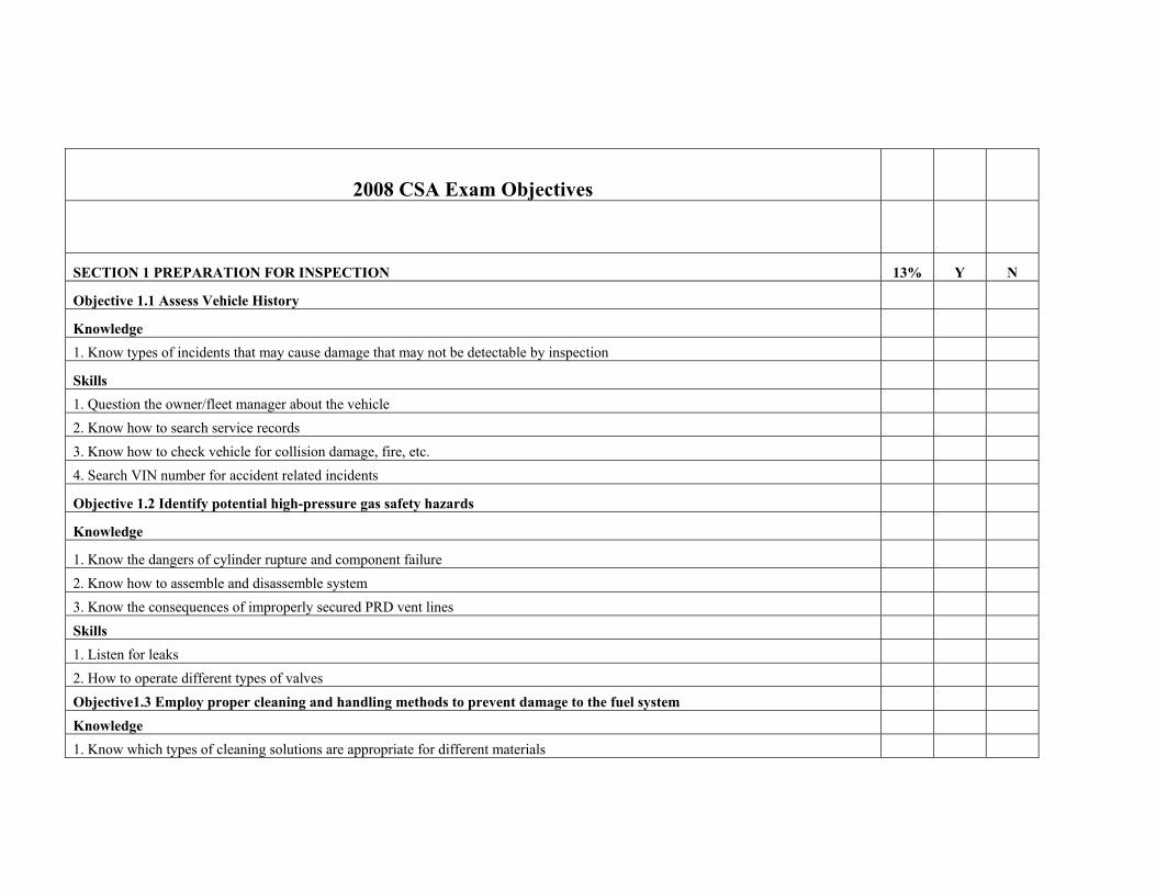
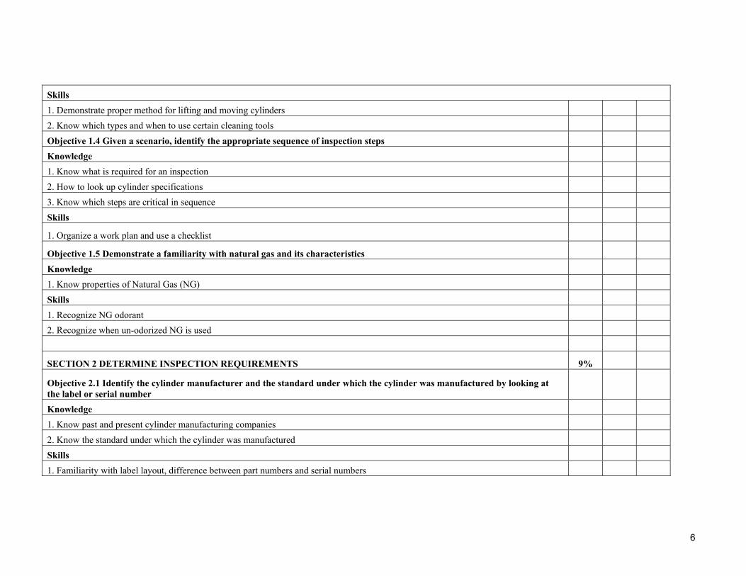
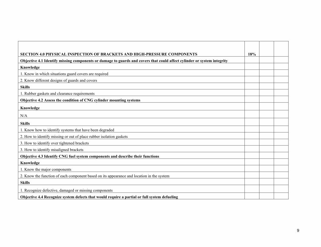
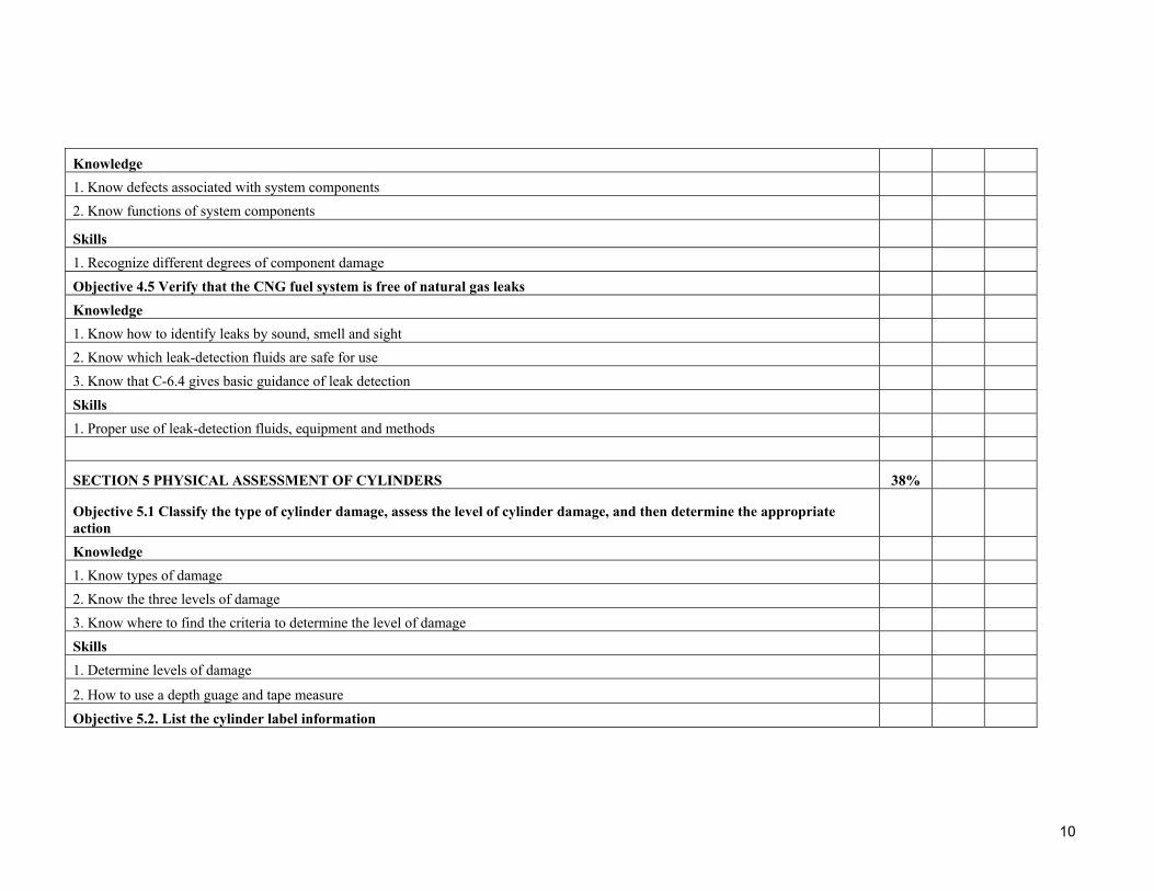
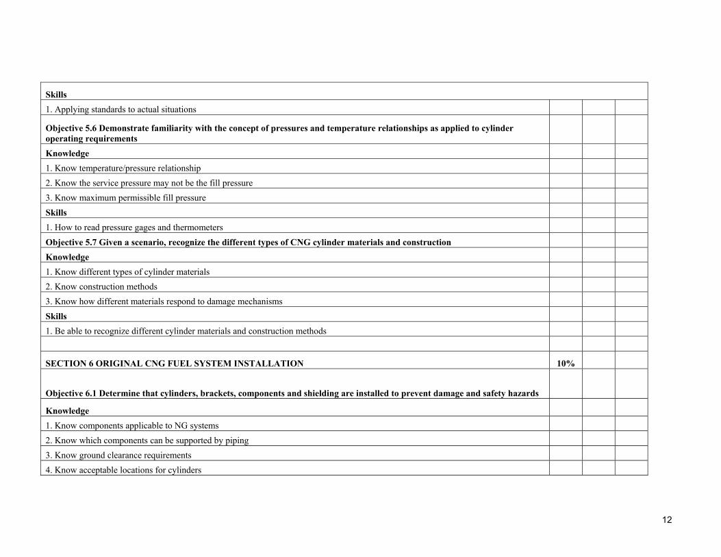
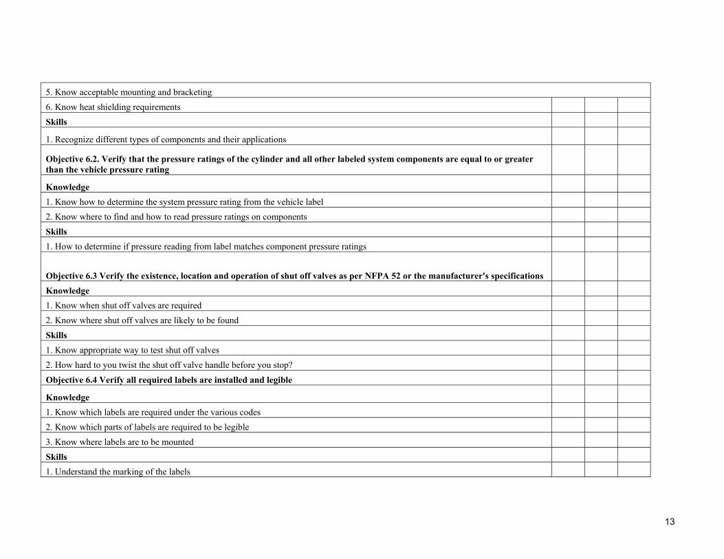
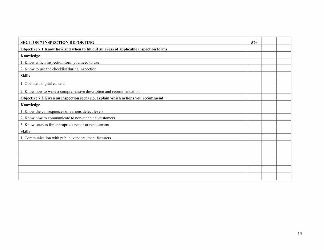
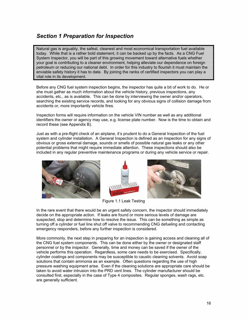
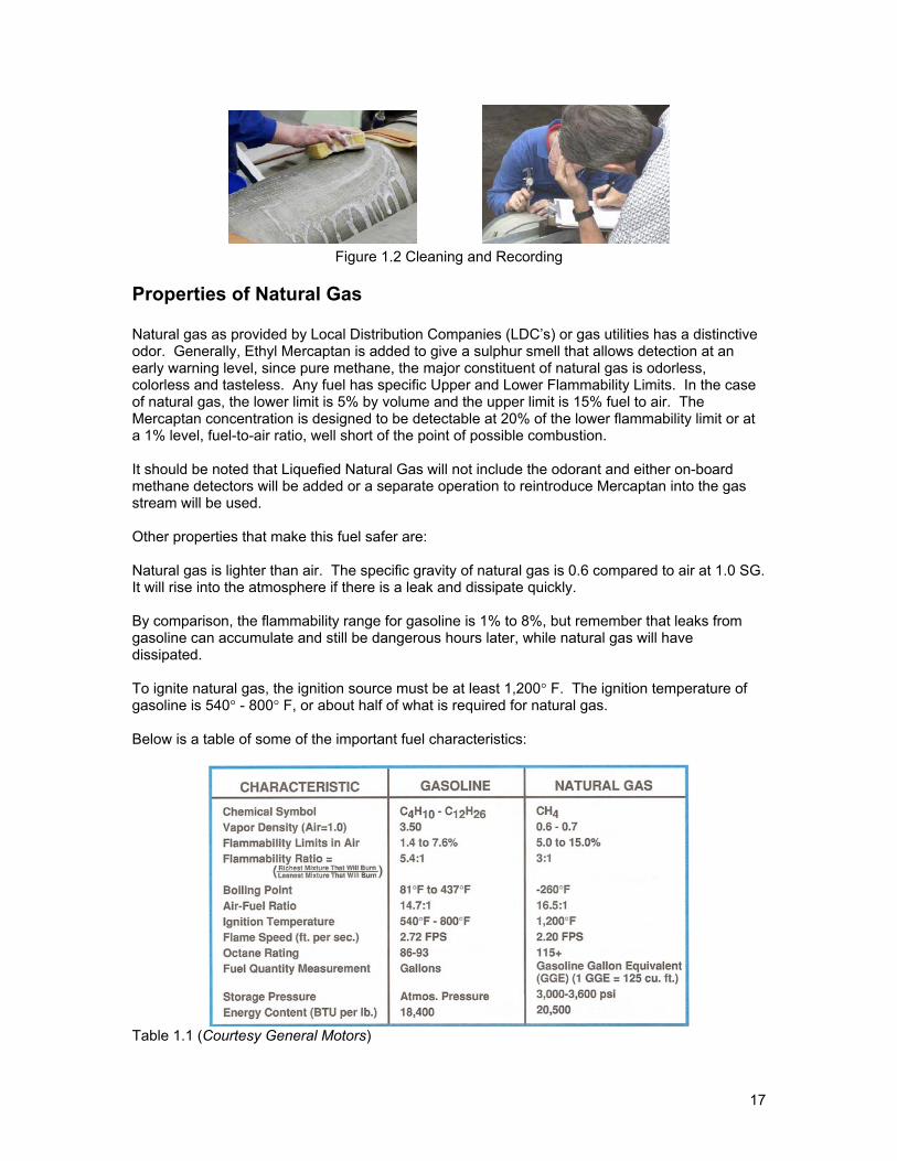
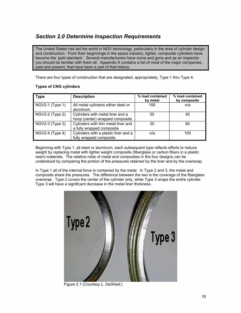
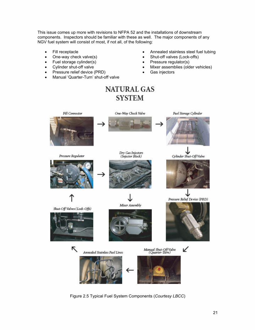
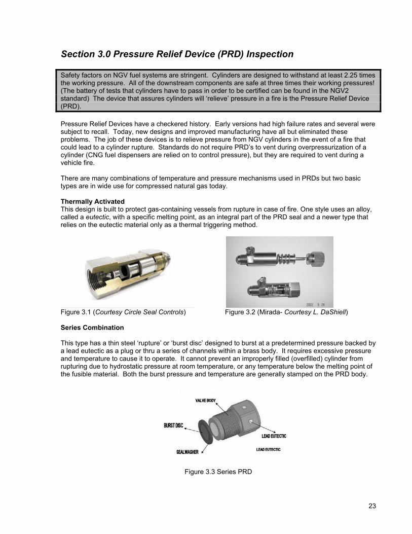
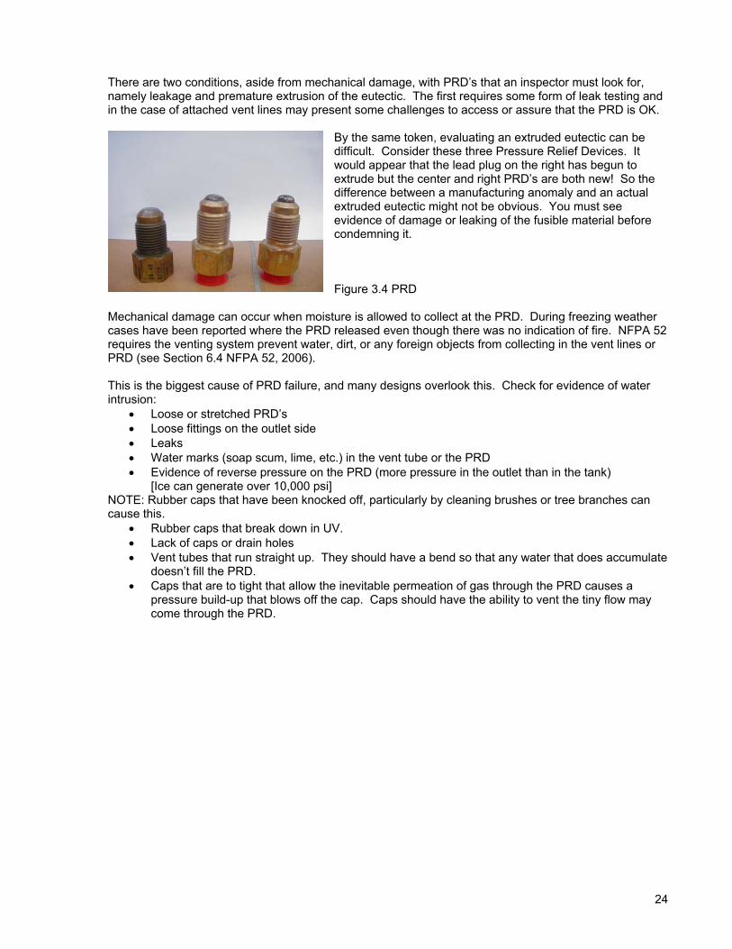
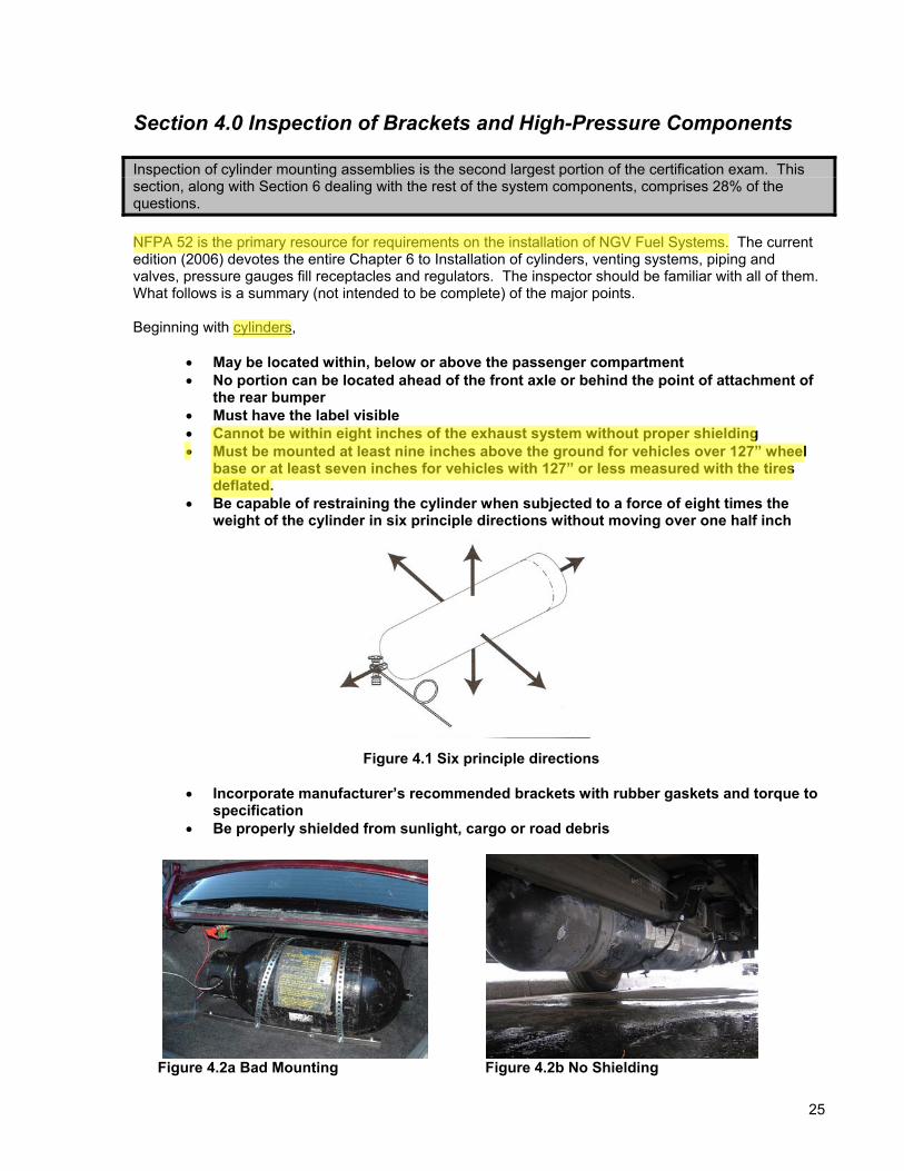
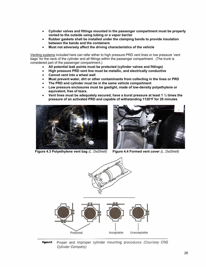
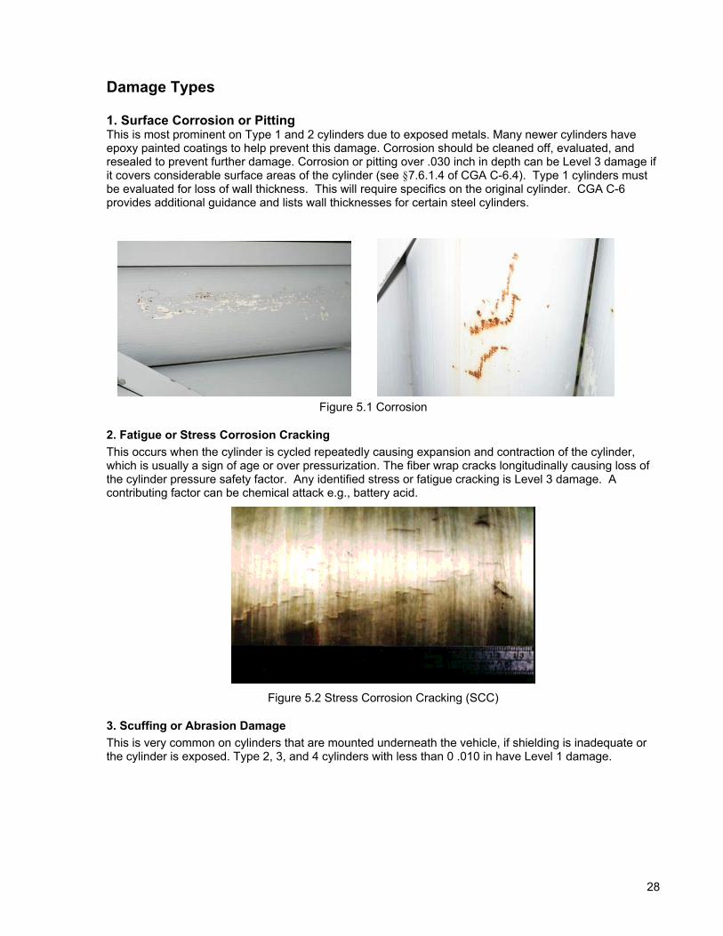
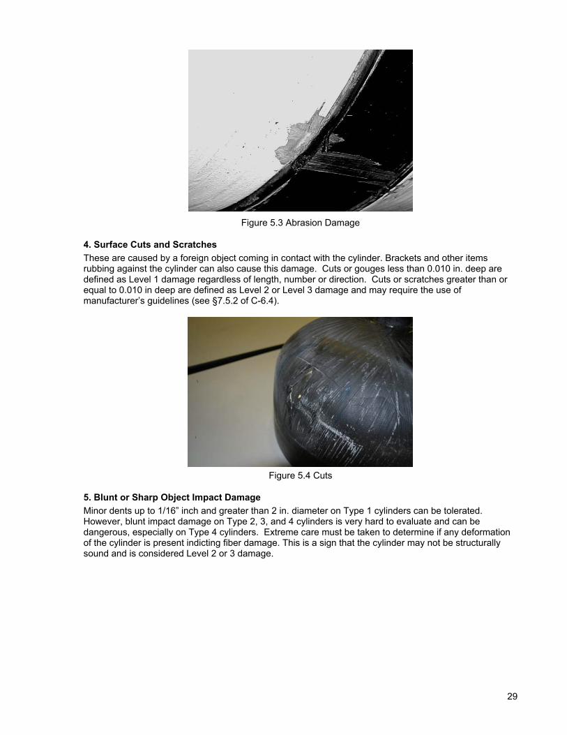
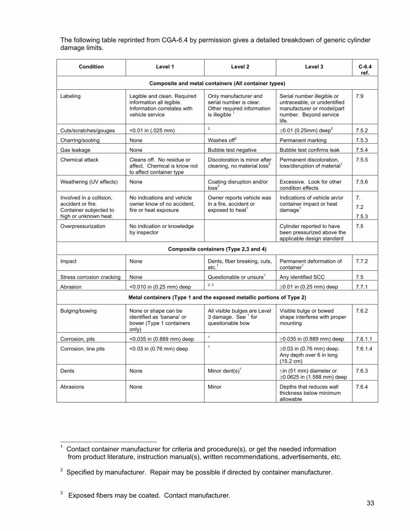
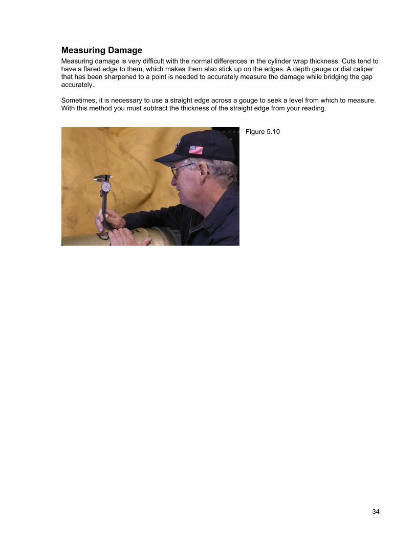
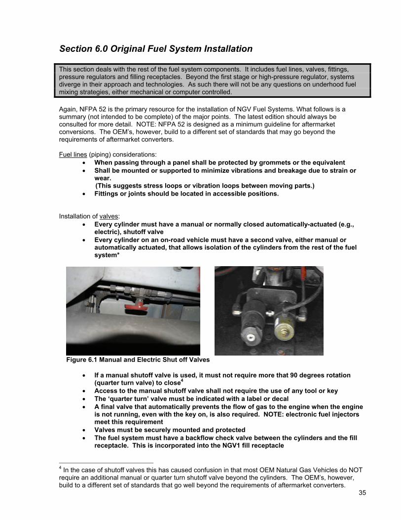
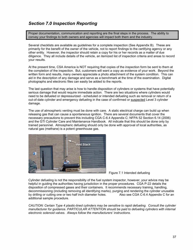
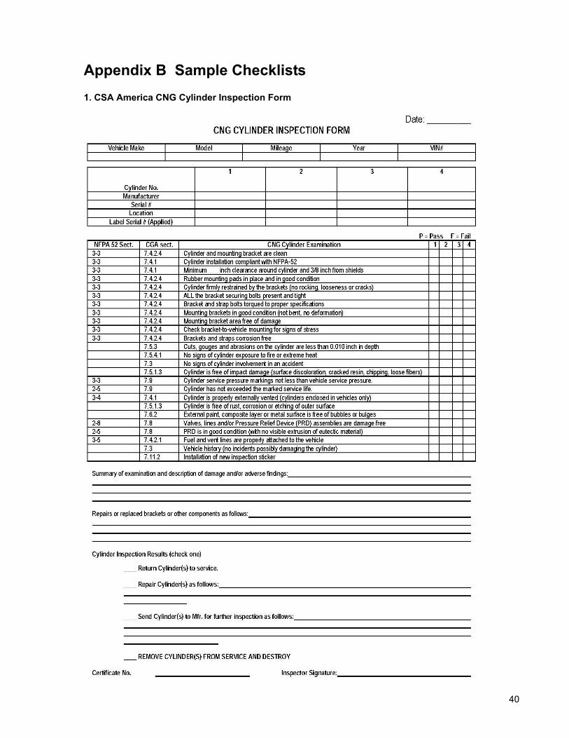
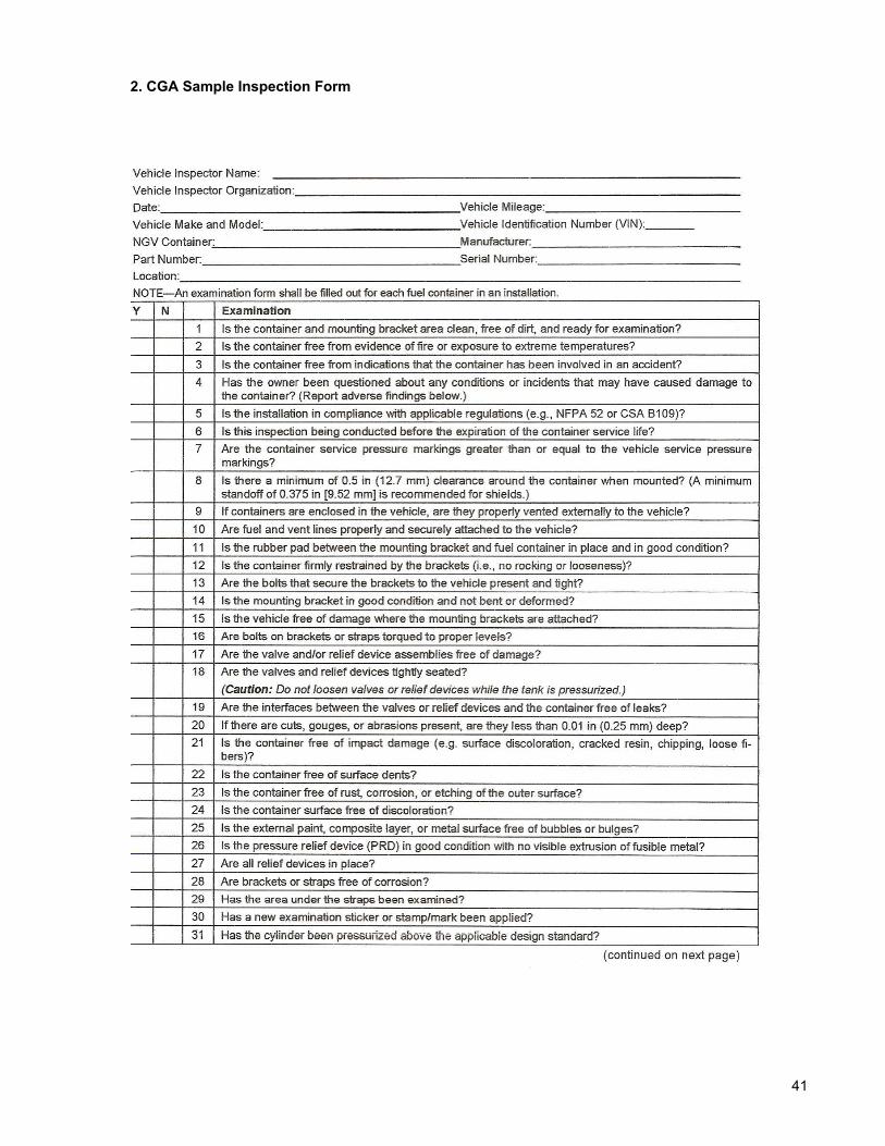
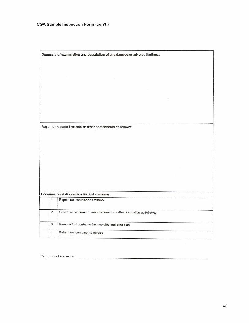
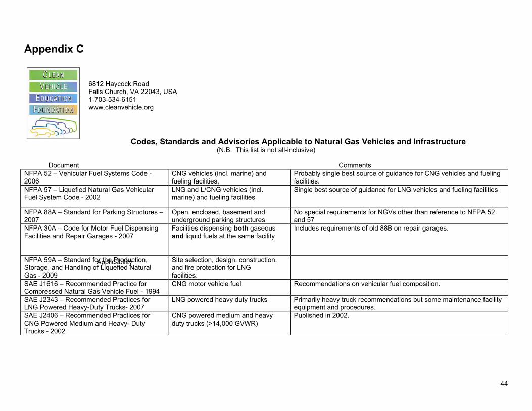
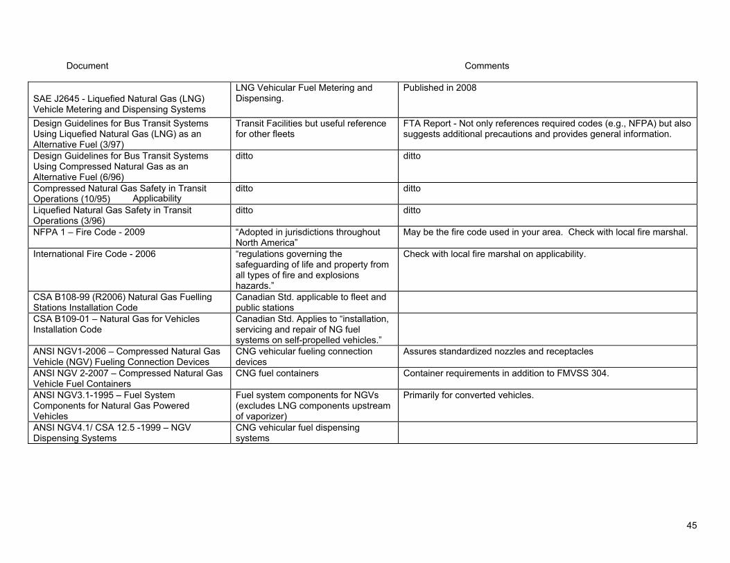
Document
Applicability
Comments
SAE J2645 - Liquefied Natural Gas (LNG) Vehicle Metering and Dispensing Systems
LNG Vehicular Fuel Metering and Dispensing
Published in 2008
Design Guidelines for Bus Transit Systems Using Liquefied Natural Gas (LNG) as an Alternative Fuel (397)
Transit Facilities but useful reference for other fleets
FTA Report - Not only references required codes (eg NFPA) but also suggests additional precautions and provides general information
Design Guidelines for Bus Transit Systems Using Compressed Natural Gas as an Alternative Fuel (696)
ditto ditto
Compressed Natural Gas Safety in Transit Operations (1095)
ditto ditto
Liquefied Natural Gas Safety in Transit Operations (396)
ditto ditto
NFPA 1 ndash Fire Code - 2009 ldquoAdopted in jurisdictions throughout North Americardquo
May be the fire code used in your area Check with local fire marshal
International Fire Code - 2006 ldquoregulations governing the safeguarding of life and property from all types of fire and explosions hazardsrdquo
Check with local fire marshal on applicability
CSA B108-99 (R2006) Natural Gas Fuelling Stations Installation Code
Canadian Std applicable to fleet and public stations
CSA B109-01 ndash Natural Gas for Vehicles Installation Code
Canadian Std Applies to ldquoinstallation servicing and repair of NG fuel systems on self-propelled vehiclesrdquo
ANSI NGV1-2006 ndash Compressed Natural Gas Vehicle (NGV) Fueling Connection Devices
CNG vehicular fueling connection devices
Assures standardized nozzles and receptacles
ANSI NGV 2-2007 ndash Compressed Natural Gas Vehicle Fuel Containers
CNG fuel containers Container requirements in addition to FMVSS 304
ANSI NGV31-1995 ndash Fuel System Components for Natural Gas Powered Vehicles
Fuel system components for NGVs (excludes LNG components upstream of vaporizer)
Primarily for converted vehicles
ANSI NGV41 CSA 125 -1999 ndash NGV Dispensing Systems
CNG vehicular fuel dispensing systems
45
Document
Applicability
Comments ANSI NGV42CSA 1252 -1999 ndash Hoses for NGVs and Dispensing Systems
CNG dispenser and vehicular hose assemblies
ANSI NGV44CSA 1254 -1999 ndash Breakaway Devices for Natural Gas Dispensing Hoses and Systems
CNG dispenser shear valves and fueling hose emergency breakaway shutoff devices
ANSI NGV46CSA 1256 -1999 ndash Manually Operated Valves for Natural Gas Dispensing Systems
Manually operated CNG valves excluding cylinder shut-off valves
ANSI NGV48CSA 128 -2002 ndash Natural Gas Vehicle Fueling Station Reciprocating Compressor Guidelines
Compressor packages containing reciprocating compressors used in CNG fueling station service
ANSI PRD1-1998 (with 1999 amp 2007 addenda) ndash Basic Requirements for Pressure Relief Devices for Natural Gas Vehicle Fuel Containers
Pressure Relief Devices for CNG Fuel Containers
CGA C-64-2007 ndash Methods for External Visual Inspection of Natural Gas Vehicle Fuel Containers and Their Installations
CNG vehicular fuel containers Referenced in ANSI NGV2
49 CFR 17856 ndash Specification 4AA welded steel cylinders
CNG cylinders for fueling stations Generally not used for new CNG fueling stations ASME vessels now generally used
49 CFR 17857 ndash Specification 4L welded insulated cylinders
LNG vehicular fuel tank requirement called out in NFPA 57
Option is meeting ASME Boiler and Pressure Vessel Code
49 CFR 571304 FMVSS 304 ndash Compressed Natural Gas Fuel Container Integrity
CNG motor vehicle fuel containers DOT Federal Motor Vehicle Safety Standard for CNG motor vehicles
49 CFR 571303 FMVSS 303 ndash Fuel System Integrity of Compressed Natural Gas Vehicles
CNG vehicles le10000 lbs GVWR and school buses
DOT Federal Motor Vehicle Safety Standard for crash test of light duty vehicle and school bus CNG fuel systems
49 CFR 39365 FMCSR ndash All Fuel Systems Commercial vehicles in interstate commerce
DOT Federal Motor Carrier Safety Regulations May have been adopted by states for intrastate application Wasnrsquot written w NGVs in mind but may be legally applicable
46
Document
Applicability
Comments 40 CFR 8033 - Controls applicable to natural gas retailers and wholesale purchaser-consumers
Retailer and wholesale purchaser-consumers of NG
EPA 12 gm limit on atmospheric venting per refueling
40 CFR 86098-8 - Emission standards for 1998 and later model year light-duty vehicles
Light-Duty Vehicles Requires NGV1 receptacles
ASME Boiler and Pressure Vessel Code Section VIII (Pressure Vessels)
Sections applicable to LNG containers used on vehicles and in fueling stations Sections applicable to containers used in CNG fueling stations
CA Code of Regulations Title 13 Div 2 Ch 4 Article 2
Fuel systems using LNG in 13 CCR 935 CNG in 13 CCR 934
CA vehicle requirements
CA Code of Regulations Title 8 Div 1 Ch 4 Subchapter 1
CNG and LNG Storage Tanks CA fuel storage requirements
CA Code of Regulations Title 13 Div 3 Ch 5 Article 3 Sec 22925
CNG sold in CA CA CNG composition requirements
TX Administrative Code Title 16 Part 1 CNG regulations in Chapter 13 LNG regulations in Chapter 14
TX requirements
Availability
National Fire Protection Association (NFPA) documents ndash contact NFPA at 1-800-344-3555 or httpcatalognfpaorg
Society of Automotive Engineers (SAE) documents ndash contact SAE at 774-726-0790 or wwwsaeorgproducts
Federal Transit Administration (FTA) documents ndash contact William Hathaway at 617-494-2081 or the National Technical Information Service at 703-605-6050 or wwwntisgov
Uniform Fire Code ndash Contact Western Fire Chiefs AssociationUniform Fire Code Association at 760-723-6911 or wwwwfcacomufca or buy from a bookstore such as AmazonCom
International Fire Code ndash Contact International Codes Council at 703-931-4533 or wwwintlcodeorg
Canadian Standards Association (CSA) documents ndash Contact CSA at 1-800-463-6727 or wwwcsaca
ANSI NGV documents ndash May be purchased from CSA at httpwwwcsa-intlorgonlinestoregetcatalogdrilldownaspParent=0ampk=3ampl=1 or ANSI at httpwebstoreansiorgansidocstoredefaultasp
47
Compressed Gas Association (CGA) documents ndash Contact CGA at 703-788-2700 or wwwcganetcom
Code of Federal Regulations (CFR) ndash Can be obtained on the web at wwwaccessgpogov
California Code of Regulations (CCR) ndash Can be obtained on the web at httpccroalcagov
Texas Administrative Code ndash Can be obtained on the web at httpinfososstatetxus80pubplsqlreadtac$ext ViewTAC
ASME Boiler and Pressure Vessel Code ndash Contact ASME at 800-843-2763 or wwwasmeorg updated 91108
48
Appendix D
There are 60 questions on the test that are graded toward certification although there may be additional sample questions inserted for evaluation but not graded They are proportioned according to the Objectives as follows
Percentage Number of Of Coverage Questions
Section 1 Preparation for Inspection 13 8
Section 2 Determine Inspection Requirements 9 5
Section 3 Pressure Relief Device Inspection 7 4
Section 4 Physical Inspection of Brackets 18 11 and HP Components
Section 5 Physical Assessment of Cylinders 38 23
Section 6 CNG Fuel System Installation 10 6
Section 7 Inspection Reporting 5 3 100 60
The test is offered throughout the year as a computer-based exam offered at designated centers all across the country and as a paper and pencil exam offered during scheduled semi-annual exam sessions Candidates for certification may download the personnel certification guide and application form from CSA Americarsquos website at httpwwwcsa-americaorgpersonnel_certificationcng_certification
Completed application forms can be submitted via email to personnelcertificationcsashyamericaorg or by faxing to (216) 520-8979 Once the application and payment are received and processed CSA will send the candidate information to the test vendor The test vendor will email the candidate the ldquoNotice to Schedulerdquo or NTS which includes instructions on scheduling their exam session Once the candidate receives their NTS they will be able to register for the exam at the test sitedate they choose Candidates must submit the scheduling request at least 10 business days prior to the requested examination date Testing sites are located throughout the United States and are normally within a short driving distance from most potential inspectors
49
Taking the Test
All of the questions are direct multiple choice or of the type rdquogiven a scenariohellipwhat would you recommendrdquo Unlike the ASE tests there are no ldquoTrueFalserdquo questions no ldquoTechnician A or Technician Brdquo questions no rdquofill in the blankrdquo and no negative questions ( eg ldquoAll of the following are true EXCEPTrdquo or rdquonone of the aboverdquo) Each question will have only one correct answer
You will have more than enough time and there is no need to feel rushed but as with all test taking keep track of the time and monitor your progress Read each question thoroughly and carefully Answer all of the questions you are confident of quickly and then go back and concentrate on those that you need more time to think about Make sure you attempt an answer on all of the questions
Sample Questions
1 The cylinder service pressure is the pressure measured at a 70 deg F b 140 deg F c 180 deg F d Ambient Temperature
2 The primary purpose of the liner in a Type 4 all composite cylinder is to a prevent the absorption of water vapor b absorb the gas c prevent gas leakage d contain gas pressure
3 An undamaged CNG cylinder with a service pressure of 3600 psig is designed with a safety factor so as not to rupture a in excess of 4500 psig b in excess of 8000 psig c in excess of 15000 psig d will not rupture at any pressure
4 In a Type 4 all-composite cylinder the portion of pressure load due to internal pressure taken up by the plastic liner is a 100 b 10 c 5 d 0
5 A composite wrap consists of a fibers embedded in a resin b a resin system c a hoop wrapped resin system d metal cords in a rubber base
50
6 The pipe or tubing attached to the pressure relief device is commonly known as a the pressure overflow line b the high pressure line c the vent line d none of the above
7 The agency having jurisdiction over the FMVSS 304 standard is a the National Highway Traffic Safety Administration (NHTSA) b the Federal Transit Administration (FTA) c the US Department of Energy (DOE) d the Clean Cities network
8 What is the useful life of cylinders made to the 1992 version of the NGV 2 standard a 5 years b 15 years c 30 years d indefinite
9 NGV 2 recommends that as a minimum cylinders should be subject to a detailed visual inspection a every year b every two years c during every refueling d every three years
10 In addition to setting forth cylinder inspection requirements the CGA C-64 standard also addresses the following topic a cylinder installation b fueling connectors c fueling station ground storage d emission requirements
11 A cylinder mounted inside a vehicle must be a protected from road debris b mounted in locations that minimize damage c vented to the outside d NFPA 52 does not allow this type of installation
51
12 During the detailed visual inspection a cut on the cylinder was found What would you recommend a the cylinder should be condemned b the cylinder manufacturer should be contacted c the level of damage should be determined d the cylinder should be immediately defueled
13 To perform the general visual inspection how much training is required a ASE Certification b two years of hands-on training c understanding and knowledge of cylinder damage d CSA Fuel System Inspection certification
14 The primary inspection method in the NGV 2 and the DOT FMVSS 304 standard is a detailed visual inspection b hydrostatic testing c ultrasonic testing d acoustic emission testing
15 One of the major safety concerns with venting natural gas from a cylinder is a overheating the vent pipe b static build-up c pollution of the environment d cuts due to high pressure
16 You are inspecting a school bus with cylinders mounted in the undercarriage and notice the road clearance is just above the 9 inch minimum Itrsquos obvious that if the bus had a flat tire the clearance would be below that What would you recommend
a As long as the clearance is about 9 inches this is not a defect b Level 1 defect record the finding and return the bus to service c Level 2 defect this must be repaired d Level 3 defect defuel and condemn the cylinder
17 An older Type 4 fiberglass wrapped cylinder is mounted under the bed of a cargo van used to transport car batteries for recycling During inspection there is evidence of chemical attack on the cylinder
Based on this information what action would you recommend a Clean any residue from the cylinder after the inspection is completed b Remove the cylinder for visual inspection c Contact the container manufacturer for guidance d Defuel the cylinder immediately and condemn it
52
18 Refer to the illustration
The driver of a converted passenger van states that he drove over a large curb and heard a loud sound The abrasion is inspected and found to have a depth of 0060 inches
What is the level of damage and recommended action
a Level 1 no action required b Level 2 contact the cylinder manufacturer for its recommend action c Level 3 contact the vehicle manufacturer for a recommend repair procedure d Level 3 condemn the cylinder
19 A surface cut in a cylinder is 2 inches long and 0040 inches deep What should be done a condemn the cylinder b consult the cylinder manufacturers guidelines to determine the damage level c remove the cylinder and consult the cylinder manufacturers guidelines d approve the cylinder for service
20 Refer to the illustration
Identify the type of cylinder a Type 1 b Type 2 c Type 3 d Type 4
ANSWER KEY 1a 2c 3b 4d 5a 6c 7a 8b 9d 10a 11c 12c 13c 14a 15b 16c 17d 18d 19b 20b
53
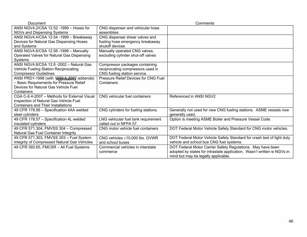
Document
Applicability
Comments ANSI NGV42CSA 1252 -1999 ndash Hoses for NGVs and Dispensing Systems
CNG dispenser and vehicular hose assemblies
ANSI NGV44CSA 1254 -1999 ndash Breakaway Devices for Natural Gas Dispensing Hoses and Systems
CNG dispenser shear valves and fueling hose emergency breakaway shutoff devices
ANSI NGV46CSA 1256 -1999 ndash Manually Operated Valves for Natural Gas Dispensing Systems
Manually operated CNG valves excluding cylinder shut-off valves
ANSI NGV48CSA 128 -2002 ndash Natural Gas Vehicle Fueling Station Reciprocating Compressor Guidelines
Compressor packages containing reciprocating compressors used in CNG fueling station service
ANSI PRD1-1998 (with 1999 amp 2007 addenda) ndash Basic Requirements for Pressure Relief Devices for Natural Gas Vehicle Fuel Containers
Pressure Relief Devices for CNG Fuel Containers
CGA C-64-2007 ndash Methods for External Visual Inspection of Natural Gas Vehicle Fuel Containers and Their Installations
CNG vehicular fuel containers Referenced in ANSI NGV2
49 CFR 17856 ndash Specification 4AA welded steel cylinders
CNG cylinders for fueling stations Generally not used for new CNG fueling stations ASME vessels now generally used
49 CFR 17857 ndash Specification 4L welded insulated cylinders
LNG vehicular fuel tank requirement called out in NFPA 57
Option is meeting ASME Boiler and Pressure Vessel Code
49 CFR 571304 FMVSS 304 ndash Compressed Natural Gas Fuel Container Integrity
CNG motor vehicle fuel containers DOT Federal Motor Vehicle Safety Standard for CNG motor vehicles
49 CFR 571303 FMVSS 303 ndash Fuel System Integrity of Compressed Natural Gas Vehicles
CNG vehicles le10000 lbs GVWR and school buses
DOT Federal Motor Vehicle Safety Standard for crash test of light duty vehicle and school bus CNG fuel systems
49 CFR 39365 FMCSR ndash All Fuel Systems Commercial vehicles in interstate commerce
DOT Federal Motor Carrier Safety Regulations May have been adopted by states for intrastate application Wasnrsquot written w NGVs in mind but may be legally applicable
46
Document
Applicability
Comments 40 CFR 8033 - Controls applicable to natural gas retailers and wholesale purchaser-consumers
Retailer and wholesale purchaser-consumers of NG
EPA 12 gm limit on atmospheric venting per refueling
40 CFR 86098-8 - Emission standards for 1998 and later model year light-duty vehicles
Light-Duty Vehicles Requires NGV1 receptacles
ASME Boiler and Pressure Vessel Code Section VIII (Pressure Vessels)
Sections applicable to LNG containers used on vehicles and in fueling stations Sections applicable to containers used in CNG fueling stations
CA Code of Regulations Title 13 Div 2 Ch 4 Article 2
Fuel systems using LNG in 13 CCR 935 CNG in 13 CCR 934
CA vehicle requirements
CA Code of Regulations Title 8 Div 1 Ch 4 Subchapter 1
CNG and LNG Storage Tanks CA fuel storage requirements
CA Code of Regulations Title 13 Div 3 Ch 5 Article 3 Sec 22925
CNG sold in CA CA CNG composition requirements
TX Administrative Code Title 16 Part 1 CNG regulations in Chapter 13 LNG regulations in Chapter 14
TX requirements
Availability
National Fire Protection Association (NFPA) documents ndash contact NFPA at 1-800-344-3555 or httpcatalognfpaorg
Society of Automotive Engineers (SAE) documents ndash contact SAE at 774-726-0790 or wwwsaeorgproducts
Federal Transit Administration (FTA) documents ndash contact William Hathaway at 617-494-2081 or the National Technical Information Service at 703-605-6050 or wwwntisgov
Uniform Fire Code ndash Contact Western Fire Chiefs AssociationUniform Fire Code Association at 760-723-6911 or wwwwfcacomufca or buy from a bookstore such as AmazonCom
International Fire Code ndash Contact International Codes Council at 703-931-4533 or wwwintlcodeorg
Canadian Standards Association (CSA) documents ndash Contact CSA at 1-800-463-6727 or wwwcsaca
ANSI NGV documents ndash May be purchased from CSA at httpwwwcsa-intlorgonlinestoregetcatalogdrilldownaspParent=0ampk=3ampl=1 or ANSI at httpwebstoreansiorgansidocstoredefaultasp
47
Compressed Gas Association (CGA) documents ndash Contact CGA at 703-788-2700 or wwwcganetcom
Code of Federal Regulations (CFR) ndash Can be obtained on the web at wwwaccessgpogov
California Code of Regulations (CCR) ndash Can be obtained on the web at httpccroalcagov
Texas Administrative Code ndash Can be obtained on the web at httpinfososstatetxus80pubplsqlreadtac$ext ViewTAC
ASME Boiler and Pressure Vessel Code ndash Contact ASME at 800-843-2763 or wwwasmeorg updated 91108
48
Appendix D
There are 60 questions on the test that are graded toward certification although there may be additional sample questions inserted for evaluation but not graded They are proportioned according to the Objectives as follows
Percentage Number of Of Coverage Questions
Section 1 Preparation for Inspection 13 8
Section 2 Determine Inspection Requirements 9 5
Section 3 Pressure Relief Device Inspection 7 4
Section 4 Physical Inspection of Brackets 18 11 and HP Components
Section 5 Physical Assessment of Cylinders 38 23
Section 6 CNG Fuel System Installation 10 6
Section 7 Inspection Reporting 5 3 100 60
The test is offered throughout the year as a computer-based exam offered at designated centers all across the country and as a paper and pencil exam offered during scheduled semi-annual exam sessions Candidates for certification may download the personnel certification guide and application form from CSA Americarsquos website at httpwwwcsa-americaorgpersonnel_certificationcng_certification
Completed application forms can be submitted via email to personnelcertificationcsashyamericaorg or by faxing to (216) 520-8979 Once the application and payment are received and processed CSA will send the candidate information to the test vendor The test vendor will email the candidate the ldquoNotice to Schedulerdquo or NTS which includes instructions on scheduling their exam session Once the candidate receives their NTS they will be able to register for the exam at the test sitedate they choose Candidates must submit the scheduling request at least 10 business days prior to the requested examination date Testing sites are located throughout the United States and are normally within a short driving distance from most potential inspectors
49
Taking the Test
All of the questions are direct multiple choice or of the type rdquogiven a scenariohellipwhat would you recommendrdquo Unlike the ASE tests there are no ldquoTrueFalserdquo questions no ldquoTechnician A or Technician Brdquo questions no rdquofill in the blankrdquo and no negative questions ( eg ldquoAll of the following are true EXCEPTrdquo or rdquonone of the aboverdquo) Each question will have only one correct answer
You will have more than enough time and there is no need to feel rushed but as with all test taking keep track of the time and monitor your progress Read each question thoroughly and carefully Answer all of the questions you are confident of quickly and then go back and concentrate on those that you need more time to think about Make sure you attempt an answer on all of the questions
Sample Questions
1 The cylinder service pressure is the pressure measured at a 70 deg F b 140 deg F c 180 deg F d Ambient Temperature
2 The primary purpose of the liner in a Type 4 all composite cylinder is to a prevent the absorption of water vapor b absorb the gas c prevent gas leakage d contain gas pressure
3 An undamaged CNG cylinder with a service pressure of 3600 psig is designed with a safety factor so as not to rupture a in excess of 4500 psig b in excess of 8000 psig c in excess of 15000 psig d will not rupture at any pressure
4 In a Type 4 all-composite cylinder the portion of pressure load due to internal pressure taken up by the plastic liner is a 100 b 10 c 5 d 0
5 A composite wrap consists of a fibers embedded in a resin b a resin system c a hoop wrapped resin system d metal cords in a rubber base
50
6 The pipe or tubing attached to the pressure relief device is commonly known as a the pressure overflow line b the high pressure line c the vent line d none of the above
7 The agency having jurisdiction over the FMVSS 304 standard is a the National Highway Traffic Safety Administration (NHTSA) b the Federal Transit Administration (FTA) c the US Department of Energy (DOE) d the Clean Cities network
8 What is the useful life of cylinders made to the 1992 version of the NGV 2 standard a 5 years b 15 years c 30 years d indefinite
9 NGV 2 recommends that as a minimum cylinders should be subject to a detailed visual inspection a every year b every two years c during every refueling d every three years
10 In addition to setting forth cylinder inspection requirements the CGA C-64 standard also addresses the following topic a cylinder installation b fueling connectors c fueling station ground storage d emission requirements
11 A cylinder mounted inside a vehicle must be a protected from road debris b mounted in locations that minimize damage c vented to the outside d NFPA 52 does not allow this type of installation
51
12 During the detailed visual inspection a cut on the cylinder was found What would you recommend a the cylinder should be condemned b the cylinder manufacturer should be contacted c the level of damage should be determined d the cylinder should be immediately defueled
13 To perform the general visual inspection how much training is required a ASE Certification b two years of hands-on training c understanding and knowledge of cylinder damage d CSA Fuel System Inspection certification
14 The primary inspection method in the NGV 2 and the DOT FMVSS 304 standard is a detailed visual inspection b hydrostatic testing c ultrasonic testing d acoustic emission testing
15 One of the major safety concerns with venting natural gas from a cylinder is a overheating the vent pipe b static build-up c pollution of the environment d cuts due to high pressure
16 You are inspecting a school bus with cylinders mounted in the undercarriage and notice the road clearance is just above the 9 inch minimum Itrsquos obvious that if the bus had a flat tire the clearance would be below that What would you recommend
a As long as the clearance is about 9 inches this is not a defect b Level 1 defect record the finding and return the bus to service c Level 2 defect this must be repaired d Level 3 defect defuel and condemn the cylinder
17 An older Type 4 fiberglass wrapped cylinder is mounted under the bed of a cargo van used to transport car batteries for recycling During inspection there is evidence of chemical attack on the cylinder
Based on this information what action would you recommend a Clean any residue from the cylinder after the inspection is completed b Remove the cylinder for visual inspection c Contact the container manufacturer for guidance d Defuel the cylinder immediately and condemn it
52
18 Refer to the illustration
The driver of a converted passenger van states that he drove over a large curb and heard a loud sound The abrasion is inspected and found to have a depth of 0060 inches
What is the level of damage and recommended action
a Level 1 no action required b Level 2 contact the cylinder manufacturer for its recommend action c Level 3 contact the vehicle manufacturer for a recommend repair procedure d Level 3 condemn the cylinder
19 A surface cut in a cylinder is 2 inches long and 0040 inches deep What should be done a condemn the cylinder b consult the cylinder manufacturers guidelines to determine the damage level c remove the cylinder and consult the cylinder manufacturers guidelines d approve the cylinder for service
20 Refer to the illustration
Identify the type of cylinder a Type 1 b Type 2 c Type 3 d Type 4
ANSWER KEY 1a 2c 3b 4d 5a 6c 7a 8b 9d 10a 11c 12c 13c 14a 15b 16c 17d 18d 19b 20b
53
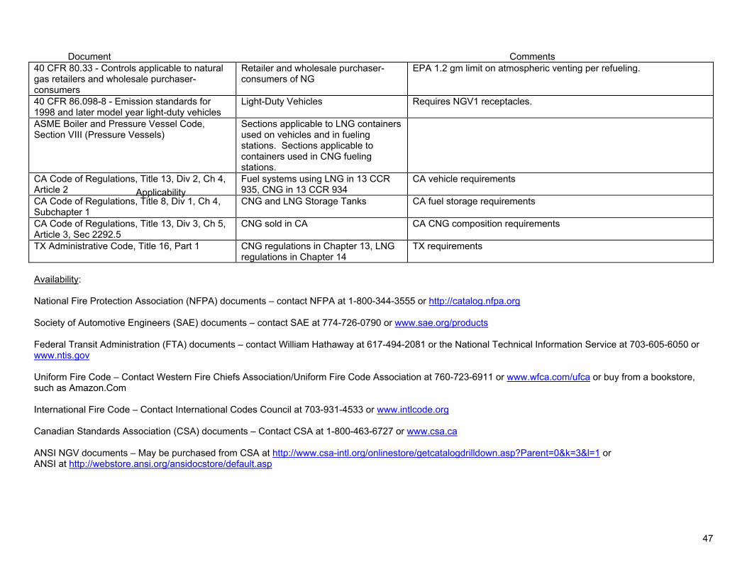
Document
Applicability
Comments 40 CFR 8033 - Controls applicable to natural gas retailers and wholesale purchaser-consumers
Retailer and wholesale purchaser-consumers of NG
EPA 12 gm limit on atmospheric venting per refueling
40 CFR 86098-8 - Emission standards for 1998 and later model year light-duty vehicles
Light-Duty Vehicles Requires NGV1 receptacles
ASME Boiler and Pressure Vessel Code Section VIII (Pressure Vessels)
Sections applicable to LNG containers used on vehicles and in fueling stations Sections applicable to containers used in CNG fueling stations
CA Code of Regulations Title 13 Div 2 Ch 4 Article 2
Fuel systems using LNG in 13 CCR 935 CNG in 13 CCR 934
CA vehicle requirements
CA Code of Regulations Title 8 Div 1 Ch 4 Subchapter 1
CNG and LNG Storage Tanks CA fuel storage requirements
CA Code of Regulations Title 13 Div 3 Ch 5 Article 3 Sec 22925
CNG sold in CA CA CNG composition requirements
TX Administrative Code Title 16 Part 1 CNG regulations in Chapter 13 LNG regulations in Chapter 14
TX requirements
Availability
National Fire Protection Association (NFPA) documents ndash contact NFPA at 1-800-344-3555 or httpcatalognfpaorg
Society of Automotive Engineers (SAE) documents ndash contact SAE at 774-726-0790 or wwwsaeorgproducts
Federal Transit Administration (FTA) documents ndash contact William Hathaway at 617-494-2081 or the National Technical Information Service at 703-605-6050 or wwwntisgov
Uniform Fire Code ndash Contact Western Fire Chiefs AssociationUniform Fire Code Association at 760-723-6911 or wwwwfcacomufca or buy from a bookstore such as AmazonCom
International Fire Code ndash Contact International Codes Council at 703-931-4533 or wwwintlcodeorg
Canadian Standards Association (CSA) documents ndash Contact CSA at 1-800-463-6727 or wwwcsaca
ANSI NGV documents ndash May be purchased from CSA at httpwwwcsa-intlorgonlinestoregetcatalogdrilldownaspParent=0ampk=3ampl=1 or ANSI at httpwebstoreansiorgansidocstoredefaultasp
47
Compressed Gas Association (CGA) documents ndash Contact CGA at 703-788-2700 or wwwcganetcom
Code of Federal Regulations (CFR) ndash Can be obtained on the web at wwwaccessgpogov
California Code of Regulations (CCR) ndash Can be obtained on the web at httpccroalcagov
Texas Administrative Code ndash Can be obtained on the web at httpinfososstatetxus80pubplsqlreadtac$ext ViewTAC
ASME Boiler and Pressure Vessel Code ndash Contact ASME at 800-843-2763 or wwwasmeorg updated 91108
48
Appendix D
There are 60 questions on the test that are graded toward certification although there may be additional sample questions inserted for evaluation but not graded They are proportioned according to the Objectives as follows
Percentage Number of Of Coverage Questions
Section 1 Preparation for Inspection 13 8
Section 2 Determine Inspection Requirements 9 5
Section 3 Pressure Relief Device Inspection 7 4
Section 4 Physical Inspection of Brackets 18 11 and HP Components
Section 5 Physical Assessment of Cylinders 38 23
Section 6 CNG Fuel System Installation 10 6
Section 7 Inspection Reporting 5 3 100 60
The test is offered throughout the year as a computer-based exam offered at designated centers all across the country and as a paper and pencil exam offered during scheduled semi-annual exam sessions Candidates for certification may download the personnel certification guide and application form from CSA Americarsquos website at httpwwwcsa-americaorgpersonnel_certificationcng_certification
Completed application forms can be submitted via email to personnelcertificationcsashyamericaorg or by faxing to (216) 520-8979 Once the application and payment are received and processed CSA will send the candidate information to the test vendor The test vendor will email the candidate the ldquoNotice to Schedulerdquo or NTS which includes instructions on scheduling their exam session Once the candidate receives their NTS they will be able to register for the exam at the test sitedate they choose Candidates must submit the scheduling request at least 10 business days prior to the requested examination date Testing sites are located throughout the United States and are normally within a short driving distance from most potential inspectors
49
Taking the Test
All of the questions are direct multiple choice or of the type rdquogiven a scenariohellipwhat would you recommendrdquo Unlike the ASE tests there are no ldquoTrueFalserdquo questions no ldquoTechnician A or Technician Brdquo questions no rdquofill in the blankrdquo and no negative questions ( eg ldquoAll of the following are true EXCEPTrdquo or rdquonone of the aboverdquo) Each question will have only one correct answer
You will have more than enough time and there is no need to feel rushed but as with all test taking keep track of the time and monitor your progress Read each question thoroughly and carefully Answer all of the questions you are confident of quickly and then go back and concentrate on those that you need more time to think about Make sure you attempt an answer on all of the questions
Sample Questions
1 The cylinder service pressure is the pressure measured at a 70 deg F b 140 deg F c 180 deg F d Ambient Temperature
2 The primary purpose of the liner in a Type 4 all composite cylinder is to a prevent the absorption of water vapor b absorb the gas c prevent gas leakage d contain gas pressure
3 An undamaged CNG cylinder with a service pressure of 3600 psig is designed with a safety factor so as not to rupture a in excess of 4500 psig b in excess of 8000 psig c in excess of 15000 psig d will not rupture at any pressure
4 In a Type 4 all-composite cylinder the portion of pressure load due to internal pressure taken up by the plastic liner is a 100 b 10 c 5 d 0
5 A composite wrap consists of a fibers embedded in a resin b a resin system c a hoop wrapped resin system d metal cords in a rubber base
50
6 The pipe or tubing attached to the pressure relief device is commonly known as a the pressure overflow line b the high pressure line c the vent line d none of the above
7 The agency having jurisdiction over the FMVSS 304 standard is a the National Highway Traffic Safety Administration (NHTSA) b the Federal Transit Administration (FTA) c the US Department of Energy (DOE) d the Clean Cities network
8 What is the useful life of cylinders made to the 1992 version of the NGV 2 standard a 5 years b 15 years c 30 years d indefinite
9 NGV 2 recommends that as a minimum cylinders should be subject to a detailed visual inspection a every year b every two years c during every refueling d every three years
10 In addition to setting forth cylinder inspection requirements the CGA C-64 standard also addresses the following topic a cylinder installation b fueling connectors c fueling station ground storage d emission requirements
11 A cylinder mounted inside a vehicle must be a protected from road debris b mounted in locations that minimize damage c vented to the outside d NFPA 52 does not allow this type of installation
51
12 During the detailed visual inspection a cut on the cylinder was found What would you recommend a the cylinder should be condemned b the cylinder manufacturer should be contacted c the level of damage should be determined d the cylinder should be immediately defueled
13 To perform the general visual inspection how much training is required a ASE Certification b two years of hands-on training c understanding and knowledge of cylinder damage d CSA Fuel System Inspection certification
14 The primary inspection method in the NGV 2 and the DOT FMVSS 304 standard is a detailed visual inspection b hydrostatic testing c ultrasonic testing d acoustic emission testing
15 One of the major safety concerns with venting natural gas from a cylinder is a overheating the vent pipe b static build-up c pollution of the environment d cuts due to high pressure
16 You are inspecting a school bus with cylinders mounted in the undercarriage and notice the road clearance is just above the 9 inch minimum Itrsquos obvious that if the bus had a flat tire the clearance would be below that What would you recommend
a As long as the clearance is about 9 inches this is not a defect b Level 1 defect record the finding and return the bus to service c Level 2 defect this must be repaired d Level 3 defect defuel and condemn the cylinder
17 An older Type 4 fiberglass wrapped cylinder is mounted under the bed of a cargo van used to transport car batteries for recycling During inspection there is evidence of chemical attack on the cylinder
Based on this information what action would you recommend a Clean any residue from the cylinder after the inspection is completed b Remove the cylinder for visual inspection c Contact the container manufacturer for guidance d Defuel the cylinder immediately and condemn it
52
18 Refer to the illustration
The driver of a converted passenger van states that he drove over a large curb and heard a loud sound The abrasion is inspected and found to have a depth of 0060 inches
What is the level of damage and recommended action
a Level 1 no action required b Level 2 contact the cylinder manufacturer for its recommend action c Level 3 contact the vehicle manufacturer for a recommend repair procedure d Level 3 condemn the cylinder
19 A surface cut in a cylinder is 2 inches long and 0040 inches deep What should be done a condemn the cylinder b consult the cylinder manufacturers guidelines to determine the damage level c remove the cylinder and consult the cylinder manufacturers guidelines d approve the cylinder for service
20 Refer to the illustration
Identify the type of cylinder a Type 1 b Type 2 c Type 3 d Type 4
ANSWER KEY 1a 2c 3b 4d 5a 6c 7a 8b 9d 10a 11c 12c 13c 14a 15b 16c 17d 18d 19b 20b
53
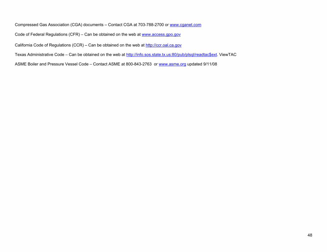
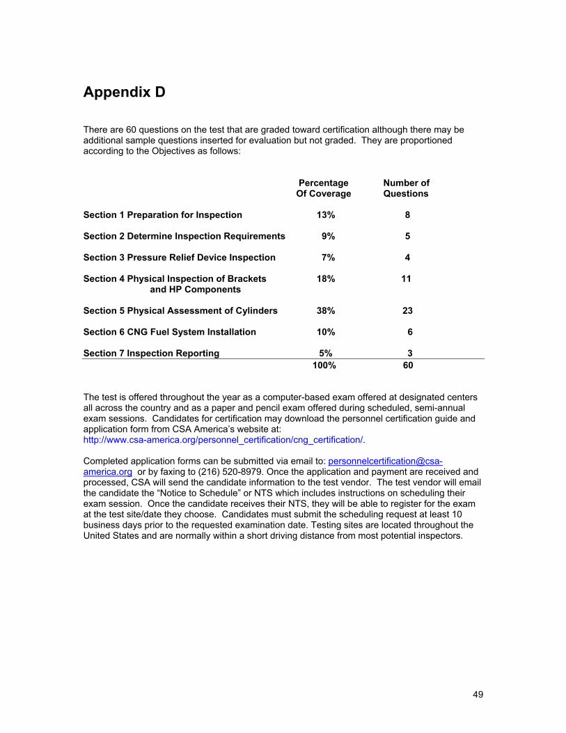
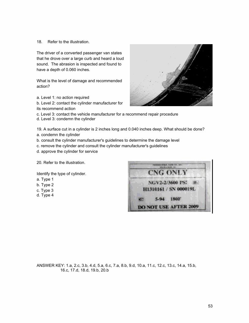