users’ manual - · pdf filecompressed natural gas fuel system ... cng vehicles and...
TRANSCRIPT

Compressed Natural Gas Fuel System
Users’ Manual
ENP-314
Rev. B: July 2017

ENP-314: CNG System Users’ Manual (Printed Copy is Not Controlled) 2 of 17
Table of Contents
1. Natural Gas Facts ................................................................................................................... 5
2. CNG Vehicles and Fuel System Configurations ................................................................. 5
3. System Configurations ........................................................................................................... 6
4. System Components and Fuel Flow .................................................................................... 6
5. Vehicle Accidents and Incidents ......................................................................................... 10
6. Fueling the CNG System ..................................................................................................... 11
7. Daily System (Pre-Drive) Checks ....................................................................................... 13
8. Maintenance Intervals .......................................................................................................... 14
9. Troubleshooting ..................................................................................................................... 14
10. CNG Fuel Cylinder and System Inspections .................................................................. 16
11. Agility Fuel Solutions Product Support ............................................................................ 17

ENP-314: CNG System Users’ Manual (Printed Copy is Not Controlled) 3 of 17
I. Proprietary Statement
The information provided in this manual is proprietary and confidential. All prior versions of this manual, including updates and revisions forwarded separately, are proprietary. The information provided by Agility Fuel Solutions to its customers and clients is solely for the use of those customers and clients. No portion of this manual may be reproduced or distributed without express written consent from Agility Fuel Solutions. Agility Fuel Solutions reserves the right to utilize the intellectual property contained within this publication as content for any other Agility publication.
Portions of this manual were drawn from information provided by suppliers of Agility Fuel Solutions and used with permission.
Agility Fuel Solutions gives express consent to authorized dealers to utilize portions of this manual, or the manual in its entirety for the purposes of providing customers and clients of Agility with information pertaining to the Agility Fuel Solutions compressed natural gas (CNG) fuel storage system with appropriate acknowledgement of copyright.
II. Preface
This manual is a basic guide for understanding and safely operating compressed natural gas (CNG) vehicle fuel systems made by Agility Fuel Solutions. If an OEM fuel system manual exists, it shall take precedence over this manual. Your system or specific components may vary from this text, but the operating principles and functions are the same.
This manual does not include details for maintaining or repairing the fuel system or the replacement of components. Refer to the Agility Fuel Solutions publication, “Truck and Tractor CNG Fuel System Operation, Maintenance & Inspection Manual,” ENP-516 for detailed maintenance and technical information.
Refer to the OEM vehicle operation or service manual for non-fuel system information.
No attempt shall be made to fill or operate the system until this manual and supporting documents have been read and fully understood.
III. Warning Statements Used in this Manual
Personal injury or death will occur if procedures are not followed.
Personal injury or death may occur if procedures are not followed.

ENP-314: CNG System Users’ Manual (Printed Copy is Not Controlled) 4 of 17
Damage to equipment, fuel system or vehicle is possible if instructions are not followed.
Best practices or hints to help an operation or procedure go smoothly.
IV. Obtaining Product Support, Service or Parts
Fuel system in- or out- of warranty product support can be obtained by calling the Agility Fuel Solutions Customer Care Hotline at 949-267-7745. Toll free: 855-500-2445.
Customer Care: [email protected]
Parts: [email protected]
Visit our website for more information, including CNG and LNG fuel system videos. Go to www.agilityfuelsolutions.com
Agility Fuel Solutions | 3335 Susan St Suite 100 | Costa Mesa, CA 92677
Revision Description Author Approved
By Date
-- Initial Release Staff Y. Coy 1/27/15
A Revised fire information, p. 5; HP filter drain interval, p. 9
W. Yoshida C. Forsberg 8/27/15
B
Deleted HP filter draining, changed cover photo, updated company name, address, logo, added ANSI Z535 signal words, removed index, general edits
W. Yoshida M. Meyer 7/26/17
ENP-314: CNG System Users’ Manual (Printed Copy is Not Controlled) 5 of 17
1. Natural Gas Facts
This manual is intended as a supplement to training in operation and maintenance of CNG fuel systems. Attempting to operate or maintain any CNG fuel system without proper training is dangerous.
Never smoke or use an open flame near a CNG vehicle.
Don’t allow sparks, flames, or heated particles to come within six feet (2m) of the vehicle.
Never attempt to depressurize or vent a system by loosening a fitting.
Never adjust, remove or tighten a fitting or connector on a fuel system that is under pressure.
Natural gas is flammable; however, it only burns within a narrow range when mixed with air in a ratio of between 5 and 15 percent. CNG will not burn in the highly concentrated form found inside the cylinders.
Natural gas is odorless, tasteless and non-toxic. That is why Mercaptan is injected into the gas – to give it that “rotten egg” odor, which helps leak detection.
Natural gas is lighter than air so it rises and diffuses into the atmosphere when released.
2. CNG Vehicles and Fuel System Configurations
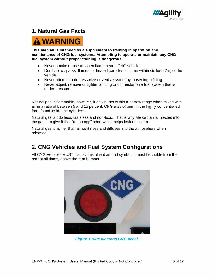
All CNG Vehicles MUST display this blue diamond symbol. It must be visible from the rear at all times, above the rear bumper.
Figure 1 Blue diamond CNG decal.

ENP-314: CNG System Users’ Manual (Printed Copy is Not Controlled) 6 of 17
3. System Configurations
Agility fuel systems are optimized to meet specific end-user applications. Fully customizable system configurations include side mount, behind the cab, front of body, roof mount for refuse, roof mount for bus and others.
Figure 2 Typical CNG system configurations. Far left: Behind the cab (BTC). Upper center: Side mount. Upper right: Refuse tail gate. Lower right: Front of
body. Lower center: Refuse roof mount.
4. System Components and Fuel Flow
4.1. CNG Storage
Fuel is stored in one or more CNG cylinders. Gas is stored in these cylinders at a nominal pressure of 3,600 pounds per square inch (psi). Every Agility system is housed in a protective structure, and can be found on the roof, at the sides, or behind the cab.
Each cylinder is protected by one or more pressure relief devices, or PRDs.

ENP-314: CNG System Users’ Manual (Printed Copy is Not Controlled) 7 of 17
Figure 3 High pressure CNG fuel flows from the cylinders to the FMM and then to the engine. The fuel system is limited to the cylinders, high pressure components
and lines to the low pressure filter.
Starting from the fuel cylinder(s), high-pressure gas flows through the cylinder shut-off valves to the Fuel Management Module (FMM). The FMM houses control valves, a filter and a pressure regulator to condition the fuel for use by the engine.
The high-pressure regulator reduces gas pressure from 3,600 psi to approximately 125 psi. Gas at 125 psi leaves the regulator and flows to the low-pressure filter, and finally to the engine. An internal regulator further reduces the gas pressure for engine consumption.
Note: The CNG fuel system ends at the input side of the low pressure fuel filter usually located in the engine bay.
4.2. Fuel Management Module (FMM)
The FMM (Figures 4 and 5) is the interface between the vehicle fuel storage and delivery system and the vehicle engine and operator. There are several FMM configurations, depending on the fuel storage system and vehicle. The FMM cabinet can be mounted on either the driver or passenger side of the vehicle.
1. The 1/4-turn manual valve has a red handle. This valve shuts off the fuel from the FMM to the engine. It is “on” or open for normal operation.
2. The standard NGV1 fuel receptacle is found across North America. Some systems also have a fast or “high-volume” fill receptacle. You can use this receptacle to fill your vehicle with a high volume nozzle.
3. The defuel receptacle permits the fuel in the cylinders to be removed when necessary.
4. The high pressure gauge indicates pressure in the cylinders and plumbing components flowing to the regulator.
CNG CYLINDERS FMM
VENT LINES NATURAL GAS ENGINE

ENP-314: CNG System Users’ Manual (Printed Copy is Not Controlled) 8 of 17
5. The low pressure gauge shows the gas pressure coming out of the regulator and going to the engine. Nominal pressure is 125 psi.
Inside the FMM
1. The manifold bleed valve and manifold – the manifold is a “hub” where the gas is distributed to various places in the system.
2. The defuel valve is used with the appropriate hose to defuel the system cylinders.
3. Safety codes require a solenoid shut-off valve that is activated by the vehicle ignition key.
Figure 4 Typical integrated FMM used in side mount systems.

ENP-314: CNG System Users’ Manual (Printed Copy is Not Controlled) 9 of 17
Figure 5 Typical standalone FMM front panel with cover removed

ENP-314: CNG System Users’ Manual (Printed Copy is Not Controlled) 10 of 17
5. Vehicle Accidents and Incidents
If the vehicle has been in an accident or fire, cylinders and system must be examined by a qualified inspector.
Refer to Agility Fuel Solutions “First Responder Guide,” ENP-084, for CNG and LNG firefighter information.
5.1. If the Vehicle is Damaged or a Gas Leak Is Detected
1. Do not approach the vehicle if any sources of ignition are present, including but not limited to: fire, sparks, electrostatic charges, power lines, lights or electronic devices.
2. Do NOT smoke or allow anyone to smoke in the vicinity of the vehicle.
3. Do NOT set out road flares.
4. Turn the ignition switch off, set the parking brake and turn off the battery at the main disconnect.
5. Close the red-handled 1/4-turn main shutoff valve on the FMM. If it is safe to do so, close all cylinder valves.
6. Check the fuel system near the damaged area for leaks by smell, sight and sound. Never use a flame to detect natural gas. CNG is odorized. A leak may cause ice or frost to form.
7. Make sure traffic and pedestrians stay clear.
8. Keep the vehicle doors open for air circulation.
9. If the vehicle is indoors, open building windows and doors to allow ventilation. Avoid turning on any lights or electronics that may spark. Pay special attention to overhead sources of ignition since natural gas is lighter than air.
10. Be aware that gas may continue to leak once the ignition is turned off and the cylinder valves are closed.
11. Check the fuel system again for leaks.
5.2. In the Event of a CNG Fire
The vehicle operator must act quickly by taking the following steps:
1. Call 9-1-1 2. Get any passengers out of the vehicle as quickly as possible. 3. Evacuate the area.
ENP-314: CNG System Users’ Manual (Printed Copy is Not Controlled) 11 of 17
The CNG cylinder pressure relief devices (PRDs) protect the system from rupturing in a fire. The PRDs MUST NOT be allowed to cool in order to activate and relieve excess pressure. PRDs typically activate between 212°F and 220°F (100°C and 104°C) and will cause high pressure CNG to vent. The CNG may ignite and add to the fire.
5.3. Emergency Shut Down Procedure
1. Turn off the battery disconnect switch. Lock and tag the switch.
2. Shut off fuel at the red 1/4-turn FMM valve.
3. Close all cylinder shut-off valves if accessible.
4. Inform emergency personnel.
Make sure you know where the manual shutoff valves are located, and what normal pressure ranges are for your system. If something does not look right, notify your fleet maintenance personnel immediately. Turn the ignition switch to “OFF” and set the parking brake.
• Normal high pressure: 500 psi minimum to 4,000 psi maximum.
• Normal low pressure: 115 psi minimum to 135 psi maximum.
6. Fueling the CNG System
6.1. Fueling Procedure
These are general guidelines. Always check with your fuel station for specific pump operating instructions and procedures.
Fueling vehicles with CNG is a relatively simple procedure
1. Open the FMM door (if applicable) and remove the dust cap from the fueling receptacle.
ENP-314: CNG System Users’ Manual (Printed Copy is Not Controlled) 12 of 17
2. Wipe the receptacle and nozzle. Check the O-ring, and then connect the nozzle from the fueling station to the fuel panel receptacle.
3. Turn the nozzle valve to the "fill" position and fuel will start to flow.
4. Continue filling until the fuel station pump shuts off automatically.
5. Remove the fueling nozzle by turning the nozzle valve to the "vent" position and release it from the receptacle. The receptacles are designed so that the nozzle will not come off if it is still under pressure.
6. Once fueling is complete, replace the cap and close the FMM door. When Agility fuel systems are equipped with optional safety interlocks (Drive Away Protection), the FMM doors or the receptacle caps must be in place in order for the engine to start.
A. When adding fuel to your vehicle, swab the station fill nozzle. Look for any
signs of oil or other contaminants. An oily or dusty condition may be an indication of poor fuel quality or a station that is not well maintained. Report this condition to the station operator.
B. Do you smell gas when filling the system? Turn off the station pump and check the O-ring inside the fill receptacle. If it is worn or damaged, clean the receptacle and replace the O-ring with a new one. If the O-ring is OK, contact your station provider.
6.2. Fast Fill/Slow Fill and Pressure/Temperature
Typically, stations fill to a service pressure of 3,600 psi. During fast filling, gas heats up as it compresses inside the cylinders, which is normal. On a hot day, pressure from the filling station will indicate full system pressure, but the fuel cylinders may not be filled completely.
For example, suppose the ambient temperature at the filling station is 120°F (50°C) in the afternoon, and the CNG dispenser stops at 3,600 psi as expected.
Later that evening, ambient temperature drops to 70°F (20°C). As the gas cools, pressure in the cylinders decrease. So instead of having a complete fill of 3,600 psi at 120°F, you have about 3,000 psi at 70°F.
Fueling stations can partially compensate for the heat generated during fast filling, but generally cannot achieve more than 70% to 80% full. Slow filling on the other hand results in nearly 100% full, because the gas is able to cool during the filling process.
When adding fuel in freezing weather, the fill receptacle, O-rings or station nozzle may freeze. This can cause the check valve inside the fill receptacle to stick open.
ENP-314: CNG System Users’ Manual (Printed Copy is Not Controlled) 13 of 17
Pushing the fill nozzle in and out of the receptacle a few times should clear the ice.
7. Daily System (Pre-Drive) Checks
1. Examine the following items each day before vehicle operation:
2. Make sure all cylinder valves and the red-handled emergency shutoff valve on the FMM are in the ON or OPEN position.
3. Check the high pressure gauge to make sure enough fuel is on-board and re-fuel if necessary.
4. Drain the low pressure filters per the engine manufacturers’ recommendation.
5. Turn the ignition key to the on position. The low pressure gauge should show about 125 psi.
6. Check the dashboard fuel gauge to make sure it is functioning.
7. Check the entire fuel system for any signs of damage or wear.
8. Check for gas leaks by smell, frost or ice and listen for hissing noises.
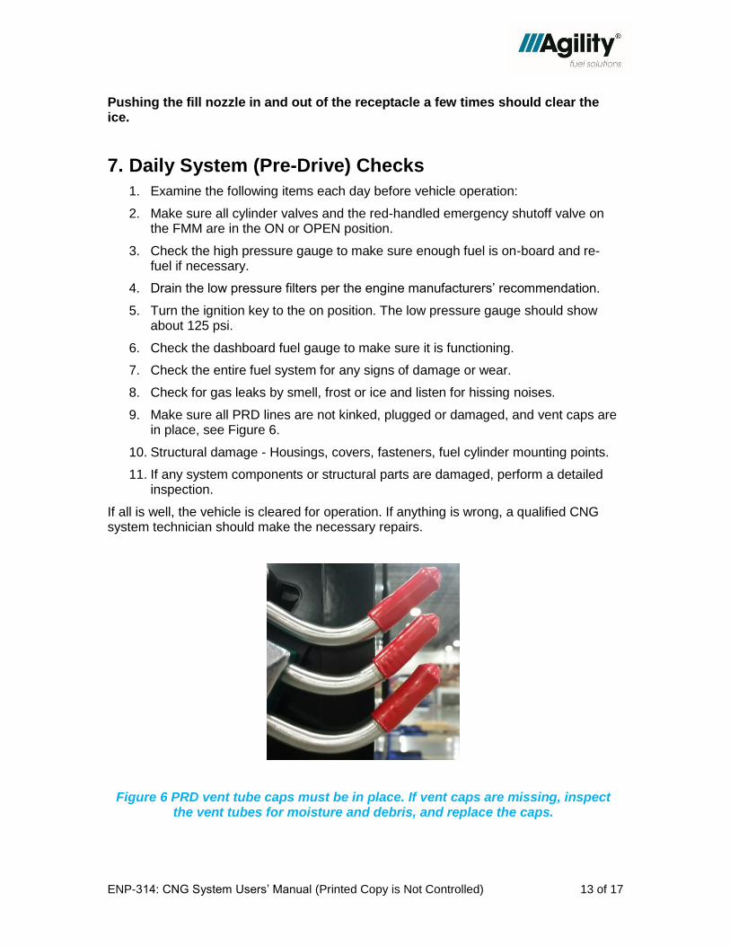
9. Make sure all PRD lines are not kinked, plugged or damaged, and vent caps are in place, see Figure 6.
10. Structural damage - Housings, covers, fasteners, fuel cylinder mounting points.
11. If any system components or structural parts are damaged, perform a detailed inspection.
If all is well, the vehicle is cleared for operation. If anything is wrong, a qualified CNG system technician should make the necessary repairs.
Figure 6 PRD vent tube caps must be in place. If vent caps are missing, inspect the vent tubes for moisture and debris, and replace the caps.

ENP-314: CNG System Users’ Manual (Printed Copy is Not Controlled) 14 of 17
The above steps are recommended each day. Information on detailed, formal CNG system inspections are in Section 10.
8. Maintenance Intervals
CNG Cylinders and System Components
Leak Test with Methane Detector Every month
Component Inspection Every month
Replace High Pressure Filter Element
Severe Duty* Every 15,000 miles/1,000 hrs./9 months
Replace High Pressure Filter Element
Normal Duty*
Every 30,000 miles**/1,000 hrs./9 months
Check PRD Vent Lines and Caps Every month (or immediately if vent cap is missing)
Inspect compressed gas cylinders See cylinder manufacturer’s label for guidelines
* Recommended change follows Cummins engine fuel filter maintenance intervals for ISL-G
**For ISX-G, interval is 50,000 mi.
9. Troubleshooting
9.1. Problem: The Engine Cranks But Won’t Start
1. Make sure the red-handled 1/4-turn shut-off valve and all cylinder valves are open.
2. See if the fuel system is providing proper fuel pressure to the engine by checking the high- and low-pressure gauges at the FMM. Normal ranges are: high pressure greater than 500 psi and low pressure 125 ± 10 psi.
3. Note: High pressure less than 500 psi may operate but the engine may not run at full power.
4. Check the condition of the chassis fuse for the FMM.

ENP-314: CNG System Users’ Manual (Printed Copy is Not Controlled) 15 of 17
9.2. Problem: The Engine Will Not Crank
1. Make sure all of the receptacle caps and FMM doors are properly closed.
2. The vehicle starting battery must be good and fully charged. Low voltage while engine is cranking may cause the solenoid valve to remain closed, preventing fuel from flowing to the system.
If the engine does not crank, check to make sure all CNG fuel system doors and fill caps are securely attached, including any remote fill receptacles at the front or rear bumper. The Drive Away Protection feature may be preventing engine start due to a fuel door ajar or loose cap.
9.3. Problem: Engine (Driver) Warning Light(s) On
If you see the amber Check Engine driver warning light, engine performance may be affected. Contact your fleet or service manager.
The red Stop Engine driver warning light means the engine may shut down automatically within 30 seconds. Immediately stop where safe, shut down the engine and contact your fleet or service manager.

ENP-314: CNG System Users’ Manual (Printed Copy is Not Controlled) 16 of 17
10. CNG Fuel Cylinder and System Inspections
Based on cylinder manufacturer recommendations and industry standard practices, visual CNG cylinder inspections should be performed at a frequency of 3 years or 36,000 miles, whichever occurs first. This is based on common passenger car or light-duty applications, where lower mileage per year is common. This inspection frequency is applied to all CNG vehicles regardless of final use application, which results in greatly varying actual frequency from a time-based perspective. The following information is accurate as of July 2014.
NOTE
According to the Canadian Natural Gas Vehicle Alliance, and the CSA Group, which offer certifications on CNG cylinder inspections, some states have specific requirements for CNG fuel cylinder inspections.
a) Arizona: Inspection is required when the vehicle is placed into service and then annually. Inspection must be performed by an individual trained by the system manufacturer.
b) Kentucky: Inspection is required every 36 months or 36,000 miles, whichever comes first, and after collision. Does not state who performs the inspection.
c) Oklahoma: Inspection is required every 36 months or 36,000 miles, whichever comes first. Inspection is performed by a certified technician.
d) Texas: The owner of the vehicle must prove that the container meets the inspection criteria of FMVSS 304. (Every 36 months or 36,000 miles, whichever occurs first.)
e) Utah: Inspection is required every 36 months or 36,000 miles, whichever occurs first. Inspection must be performed by a CSA certified technician.
f) West Virginia: Does not state the frequency of inspection, however, all CNG activity must be overseen by a CSA certified technician. Note, this legislation is not signed into law yet.
g) Ohio – coming soon
Where possible, Agility Fuel Solutions recommends a practical alternative schedule for detailed fuel system inspections – selected by the fleet manager or vehicle owner.
Use either:
1. The common recommendation of every 3 years or 36,000 miles, whichever occurs first, OR
2. after every 1 year or 100,000 miles, whichever occurs first
In addition, Agility recommends a daily walk-around or pre- and post-trip visual inspection be performed, regardless of which detailed fuel system inspection schedule is followed.
NOTE: Inspections must be performed by qualified inspectors using guidelines from the fuel cylinder manufacturer in addition to the guidelines listed in this manual.

ENP-314: CNG System Users’ Manual (Printed Copy is Not Controlled) 17 of 17
If a CNG-fueled vehicle has been involved in an accident or fire, the system and cylinders must be inspected by a certified (CGA C-6.4) or other qualified CNG fuel system inspector.
11. Agility Fuel Solutions Customer Care
If you are experiencing a problem with your vehicle or are uncertain about any process or procedure, you can contact your local Agility Fuel Solutions service provider or contact the Agility Fuel Solutions Customer Care group directly at 949-267-7745 or e-mail us at [email protected].
When you e-mail or call, we will need your name, phone number, e-mail address, and the vehicle information: VIN, unit number, year, make, model, the name of the vehicle owner and its current location. We will assign a service advisor who will contact you and make arrangements to have your vehicle fixed or a part shipped.
For more details, consult additional Agility resources such as Operation Manuals, Parts Manuals or fuel system videos. These are available on our website, www.agilityfuelsolutions.com