class c - fusetek.com · n provides type 2 protection for iec and nema control. n fully plated...
TRANSCRIPT
3
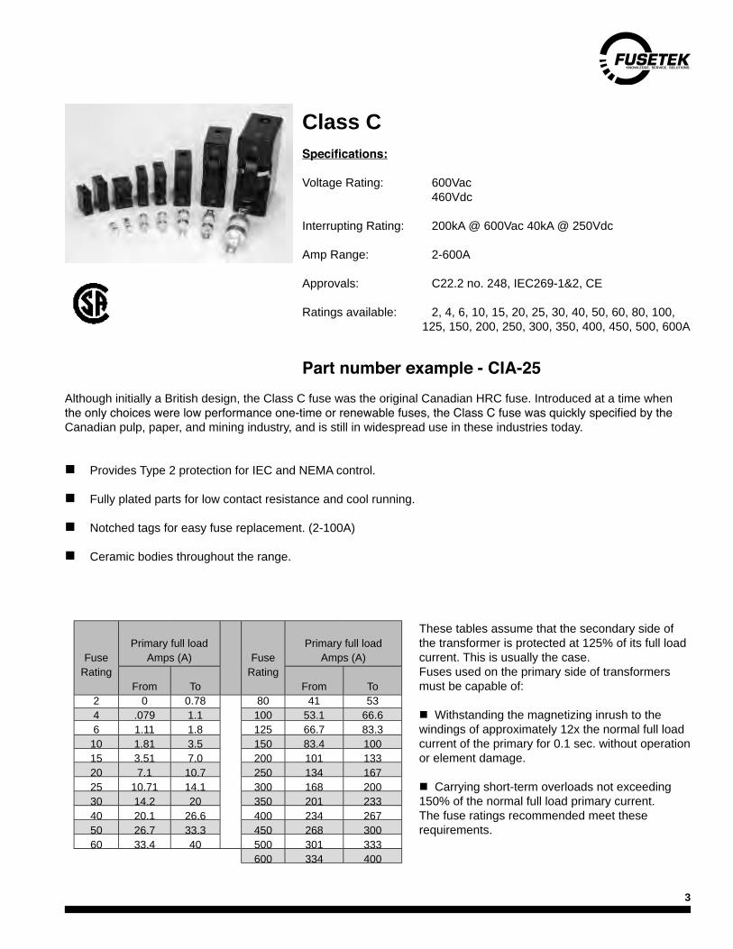
Class CSpecifications:
Voltage Rating: 600Vac 460Vdc
Interrupting Rating: 200kA @ 600Vac 40kA @ 250Vdc
Amp Range: 2-600A
Approvals: C22.2 no. 248, IEC269-1&2, CE
Ratings available: 2, 4, 6, 10, 15, 20, 25, 30, 40, 50, 60, 80, 100, 125, 150, 200, 250, 300, 350, 400, 450, 500, 600A
Although initially a British design, the Class C fuse was the original Canadian HRC fuse. Introduced at a time when the only choices were low performance one-time or renewable fuses, the Class C fuse was quickly specified by the Canadian pulp, paper, and mining industry, and is still in widespread use in these industries today.
Part number example - CIA-25
n Provides Type 2 protection for IEC and NEMA control.
n Fully plated parts for low contact resistance and cool running.
n Notched tags for easy fuse replacement. (2-100A)
n Ceramic bodies throughout the range.
Fuse Rating
Primary full loadAmps (A) Fuse
Rating
Primary full loadAmps (A)
From To From To2 0 0.78 80 41 534 .079 1.1 100 53.1 66.66 1.11 1.8 125 66.7 83.310 1.81 3.5 150 83.4 10015 3.51 7.0 200 101 13320 7.1 10.7 250 134 16725 10.71 14.1 300 168 20030 14.2 20 350 201 23340 20.1 26.6 400 234 26750 26.7 33.3 450 268 30060 33.4 40 500 301 333
600 334 400
These tables assume that the secondary side of the transformer is protected at 125% of its full load current. This is usually the case.Fuses used on the primary side of transformers must be capable of:
n Withstanding the magnetizing inrush to the windings of approximately 12x the normal full load current of the primary for 0.1 sec. without operation or element damage.
n Carrying short-term overloads not exceeding 150% of the normal full load primary current.The fuse ratings recommended meet these requirements.

4
Motor Application
Standard motor starting duty is defined as motors having 6 x nominal FLA starting current, maximum 10 second acceleration time and 4 evenly spaced starts per hour in a maximum 32 degree C ambient. If any of these conditions are exceeded, use the Heavy duty column.
The motor data and fuse ratings presented are based on 1800 rpm high efficiency motors. For operating conditions ormotor types outside the scope of these tables, please request a copy of our Fusesoft v4.0 fuse selection software orcontact our offices with application details.
How to use motor tables
� Select voltage range.� Select standard (STD) or heavy duty column column.� Read off amp rating of fuse opposite appropriate motor HP size and under appropriate column.
Motor Selection table for Class C fuses575/600Vac 460/480Vac 230/240Vac
Motor data Fuse rating Motor data Fuse rating Motor data Fuse rating
HP FLAOverload type
HP FLAOverload type
HP FLAOverload type
STD HEAVY STD HEAVY STD HEAVY3/4 1.1 4 4 3/4 1.4 6 6 3/4 2.8 10 101 1.4 6 6 1 1.8 6 6 1 3.6 15 15
1.5 2.1 6 6 1.5 2.6 10 10 1.5 5.2 15 152 2.7 10 10 2 3.4 10 15 2 6.8 20 203 3.9 15 15 3 4.8 15 15 3 9.6 25 255 6.1 15 20 5 7.6 20 20 5 15.2 30 40
7.5 9 20 25 7.5 11 25 30 7.5 22 40 5010 11 25 30 10 14 30 30 10 28 60 6015 17 30 40 15 21 40 50 15 42 80 8020 22 40 50 20 27 50 60 20 54 100 10025 27 50 60 25 34 80 80 25 68 125 12530 32 60 80 30 40 80 80 30 80 125 15040 41 80 80 40 52 100 100 40 104 150 20050 52 80 100 50 65 100 125 50 130 200 25060 62 100 125 60 77 125 125 60 154 250 25075 77 125 125 75 96 150 150 75 192 250 300100 99 150 150 100 124 200 200 100 248 300 350125 125 200 200 125 156 250 250 125 312 400 450150 144 200 250 150 180 250 300 150 360 450 500200 192 250 300 200 240 300 350 200 480 500 600250 237 300 350 250 296 350 400 250 - - -300 284 350 400 300 354 400 450 300 - - -350 328 400 450 350 410 450 500 350 - - -400 374 450 500 400 467 500 600 400 - - -
5
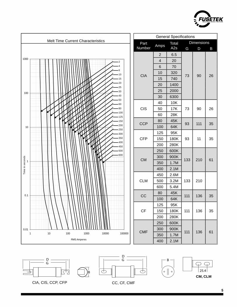
General SpecificationsPart
Number Amps TotalA2s
DimensionsG D B
CIA
2 6.5
73 90 26
4 206 7010 32015 74020 140025 200030 6300
CIS40 10K
73 90 2650 17K60 28K
CCP80 45K
93 111 35100 64K
CFP125 95K
93 11 35150 180K200 280K
CM
250 600K
133 210 61300 900K350 1.7M400 2.1M
CLM450 2.6M
133 210500 3.2M600 5.4M
CC80 45K
111 136 35100 64K
CF125 95K
111 136 35150 180K200 280K
CMF
250 600K
111 136 61300 900K350 1.7M400 2.1M
CC, CF, CMF
CM, CLM
DBG
25.4B
DG
0.01
0.1
1
10
100
1000
1 10 100 1000 10000 100000
RMS Amperes
Tim
e in
sec
onds
246
101520
253040
5060
80100125
150200250
300350400
450500600
Melt Time Current Characteristics
CIA, CIS, CCP, CFP CC, CF, CMF

6
Class CA, CBC series fuses are British dimension current limiting HRC fuse with very compact dimensions. They are used for a wide variety of control appli-cations where excellent current limitation and compact dimensions are required.
CA / CB Series fuses can be used on any 600VAC or less circuit.
SS fuses are used only for replacement purposes in imported equipment.
All metal parts are tin plated for low resistance.• Ceramic bodies.•
General Specifications - Class CA / CBC-N CNS SS
Voltage Rating
600VAC250VDC
600VAC250VDC
240VAC
InterruptingRating
200kA @ 600VAC80kA @ 250VDC
80kA @ 240VAC
Amp Ratings
1, 3, 6, 10, 15, 20A
1, 3, 6, 10, 15, 20, 25, 30A
2, 4, 6, 10, 15,20, 25, 32A
Speed Fast Fast MediumApprovals CSA C22.2 No. 106 IEC269-2CSA Class HRC1-CA HRC1-CB -
Ballast Current
CNS / CN Fuses
From To0 0.15A 1A0.16A 0.47A 3A0.48A 1.42A 6A1.43A 2.16A 10A2.17A 4.50A 15A4.51A 8A 20A8.1A 10.3A 25A10.4A 14.3A 30A
14mm
3.6mm58mm
14mm
51mm
44mm
C-N Series CNS Series
CBCA
GEC C-N & CNS Series
RMS Amperes
7
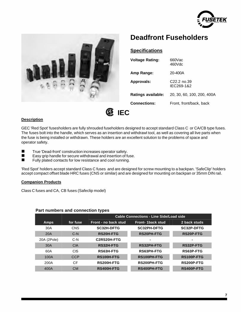
Deadfront Fuseholders
Specifications
Voltage Rating: 660Vac460Vdc
Amp Range: 20-400A
Approvals: C22.2 no.39IEC269-1&2
Ratings available: 20, 30, 60, 100, 200, 400A
Connections: Front, front/back, back
Description
GEC 'Red Spot' fusesholders are fully shrouded fuseholders designed to accept standard Class C or CA/CB type fuses. The fuses bolt into the handle, which serves as an insertion and withdrawl tool, as well as covering all live parts when the fuse is being installed or withdrawn. These holders are an excellent solution to the problems of space and operator safety.
� True 'Dead-front' construction increases operator safety.� Easy grip handle for secure withdrawal and insertion of fuse.� Fully plated contacts for low resistance and cool running.
'Red Spot' holders accept standard Class C fuses and are designed for screw mounting to a backpan. 'SafeClip' holdersaccept compact offset blade HRC fuses (CNS or similar) and are designed for mounting on backpan or 35mm DIN rail.
Companion Products
Class C fuses and CA, CB fuses (Safeclip model)
Part numbers and connection types
Amps for fuseCable Connections - Line Side/Load side
Front - no back stud Front- 1back stud 2 back studs30A CNS SC32H-DFTG SC32PH-DFTG SC32P-DFTG20A C-N RS20H-FTG RS20PH-FTG RS20P-FTG
20A (2Pole) C-N C2RS20H-FTG - -30A CIA RS32H-FTG RS32PH-FTG RS32P-FTG60A CIS RS63H-FTG RS63PH-FTG RS63P-FTG100A CCP RS100H-FTG RS100PH-FTG RS100P-FTG200A CF RS200H-FTG RS200PH-FTG RS200P-FTG400A CM RS400H-FTG RS400PH-FTG RS400P-FTG
IEC
8
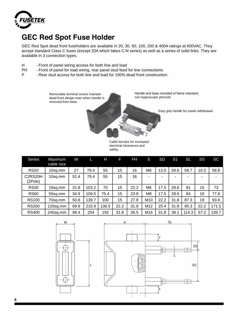
GEC Red Spot Fuse HolderGEC Red Spot dead front fuseholders are available in 20, 30, 60, 100, 200 & 400A ratings at 600VAC. They accept standard Class C fuses (except 20A which takes C-N series) as well as a series of solid links. They are available in 3 connection types.
H - Front of panel wiring access for both line and loadPH - Front of panel for load wiring, rear panel stud feed for line connections.P - Rear stud access for both line and load for 100% dead front construction.
Series Maximumcable size
W L H F FH S SD S1 SL SS SC
RS20 10sq.mm 27 79.4 55 15 16 M6 13.5 28.6 58.7 10.3 58.8C2RS20H
(2Pole)10sq.mm 52.4 79.4 55 15 16 - - - - - -
RS30 16sq.mm 31.8 103.2 70 15 22.2 M6 17.5 28.6 81 15 73RS60 50sq.mm 34.9 109.5 75.4 15 23.8 M8 17.5 28.6 84 16 77.8RS100 70sq.mm 50.8 139.7 100 15 27.8 M10 22.2 31.8 87.3 19 93.6RS200 120sq.mm 69.9 215.9 136.5 22.2 31.8 M12 25.4 31.8 95.3 22.2 171.5RS400 240sq.mm 98.4 254 192 31.8 36.5 M16 31.8 38.1 114.3 57.2 139.7
Handle and base moulded of flame retardant, non-hygroscopic phenolic
Easy grip handle for easier withdrawal.
Removable terminal covers maintain dead-front design even when handle is removed from base.
Cable ferrules for increased electrical clearances and safety.
W
L
H SL
F
S
SS
SC
F

9
Safety lockouts for Red Spot Fuse Holders
DescriptionTo met current safety requirements, a lockable insert is available for all our Red Spot Dead Front fuse holders up to 100A. This insert takes place of the fuse handle, and with a padlock, ensures that inadvertent reconnections of isolated circuits are not made during maintenance work.
• Allows Red Spot holders to meet lockout requirements.• Easy to insert.• Safety yellow for immediate visual identification.
Red SpotHolder series
Lock outP/N
RS20 RS20LOCKRS32 RS32LOCKRS63 RS63LOCKRS100 RS100LOCKSC32 SC32LOCKSC63 SC63LOCK
Specifications.
Hasp Diameter o.25" or less
10
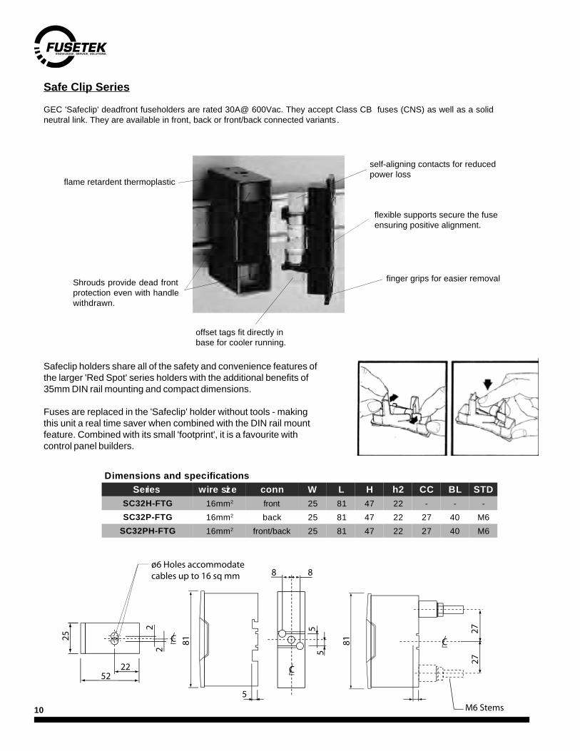
GEC 'Safeclip' deadfront fuseholders are rated 30A@ 600Vac. They accept Class CB fuses (CNS) as well as a solidneutral link. They are available in front, back or front/back connected variants .
Safeclip holders share all of the safety and convenience features ofthe larger 'Red Spot' series holders with the additional benefits of35mm DIN rail mounting and compact dimensions.
Fuses are replaced in the 'Safeclip' holder without tools - makingthis unit a real time saver when combined with the DIN rail mountfeature. Combined with its small 'footprint', it is a favourite withcontrol panel builders.
flame retardent thermoplastic
self-aligning contacts for reducedpower loss
flexible supports secure the fuseensuring positive alignment.
finger grips for easier removalShrouds provide dead frontprotection even with handlewithdrawn.
offset tags fit directly inbase for cooler running.
Dimensions and specificationsSeries wire size conn W L H h2 CC BL STD
SC32H-FTG 16mm2 front 25 81 47 22 - - -SC32P-FTG 16mm2 back 25 81 47 22 27 40 M6
SC32PH-FTG 16mm2 front/back 25 81 47 22 27 40 M6
Safe Clip Series
5222
22
C25 81
55
5
8 8
C
C
2727
M6 Stems
81
o6 Holes accommodatecables up to 16 sq mm

11
SIBA 600V 'ZS' DIN fuseholdersZS modules are DIN rail mountable, dead front fuseholders that accept standard metric ferrule fuses.
ZS modules in 14 x 51mm and 22 x 58mm versions are available with a microswitch option.
n UR recognised. (file E186970)n Available in 1, 2, & 3 pole versions.
Size 10 x 38Part No. 51 063 04.DC for 1000 V Dc
51 063 04 1 pol.51 063 04.2 2 pol51 063 04.3 3 pol
Power acceptance: 4W
A 307" (78 mm) H 3.13" (79.5 mm)B 0.70" (17.8 mm) J 1.69" (43 mm)C 1.40" (35.6 mm) K 0.40" (10 mm)D 2.10" (53.4 mm) M 1.77" (45 mm)E 2.80" (71.2 mm) N 0.65" (16.5 mm)F 2.20" (56 mm) P 0.13" (3.2 mm)G 2.40" (61 mm) W 0.10" (2.5 mm)
Size 14 x 51Part No. 51 058 04 51 058 04.S 1 pol.
51 058 04.2 2 pol51 058 04.3 51 058 04.3S 3 pol
S= Microswitch
Power acceptance: 6W
A 404" (102.5 mm) M 1.77" (45 mm)B 1.04" (26.5 mm) N 1.69" (32.5 mm)C 2.10" (53 mm) P 0.40" (10.5 mm)D 3.13" (79.5 mm) R 1.48" (37.5 mm)E 4.17" (106 mm) S 0.30" (8 mm)F 2.66" (67.5 mm) T 0.80" (20.5 mm)G 3.00" (76 mm) U 0.33" (8.5 mm)H 3.70" (94.2 mm) W 0.1" (2.5 mm)J 2.07" (52.5 mm) X 3.17" (80.5 mm)K 0.30" (8 mm) Z 0.17" (4.4 mm)
Size 22 x 58Part No. 51 060 04 51 063 04.S 1 pol.
51 060 04.2 2 pol51 060 04.3 51 063 04.3S 3 pol
S= Microswitch
Power acceptance: 12W
A 5.50" (140 mm) M 1.77" (45 mm)B 1.40" (35.6 mm) N 2.00" (50.5 mm)C 2.80" (71.2 mm) P 0.30" (7.5 mm)D 4.20" (106.8 mm) R 1.57" (40 mm)E 5.60" (142.4 mm) S 0.30" (8 mm)F 2.97" (75.5 mm) T 1.06" (27 mm)G 3.44" (87.5 mm) W 0.10" (2.5 mm)H 4.35" (110.5 mm) X 4.30" (109.5 mm)J 2.10" (53 mm) Z 0.17" (4.4 mm)K 0.63" (16 mm)
30A
40A
100A

12
Dimensions: Include dotted line for D65U
ElastimoldSpecifications
Voltage Rating: 600Vac dialectric - 2.2kVac / 1 min.Ampere Rating: 30A max.Load Break Rating: 15A - 250VacMaterial: SantopreneWaterproof: Submersible to 12" for 24hr.Wire Size - Std #14 - #6 awg copper LC version #4 - #2 awg copperApprovals CSA c22.2 no. 39
Description
65U and D65U are fully waterproof in-line fuseholders designed to accept standard midget (13/32 x 1-1/2" & 10 x 38mm) fuses. They have integral moulded boots and 'break-away' safety design as standard features. Their primary use is in the fusing of street lighting ballasts, but they could be used for any application requiring weatherproof or waterproof fuseholders.
Features & Benefits
n Will accept any 13/32 x 1-1/2" or 10 x 38mm fuse. (except glass body or indicating types.)n Integral boots and 'Break-away' feature means no costly add-ons.n Fully waterproof to 12" submersion (when installed per mfrs. recommendations)n Flexible 'Santoprene' rubber has excellent environmental withstand.n Load-break capability - (15A at 250Vac)n Standard unit covers #14 through #6 CU awg wire size.
See PowrGard PF101 digest for Littelfuse LEB series 'screw-apart' in-line waterproof fuseholders.
13
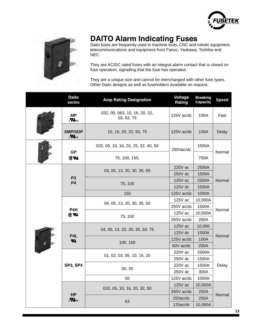
Daito series Amp Rating Designation Voltage
Rating Breaking Capacity Speed
MP 032, 05, 063, 10, 16, 20, 32, 50, 63, 75 125V ac/dc 100A Fast
SMP/SDP 10, 16, 20, 32, 50, 75 125V ac/dc 100A Delay
GP032, 05, 10, 16, 20, 25, 32, 40, 50
250Vac/dc
1500ANormal
75, 100, 150, 750A
P3 P4
03, 05, 13, 20, 30, 35, 50 220V ac 2500A
Normal250V dc 1500A
75, 100125V ac 2500A125V dc 1500A
150 125V ac/dc 1000A
P4H04, 05, 13, 20, 30, 35, 50
125V ac 10,000A
Normal250V ac/dc 1500A
75, 100125V ac 10,000A
250V ac/dc 200A
P4L 04, 05, 13, 20, 30, 35, 50, 75
125V ac 10,000
Normal125V dc 1500A
100, 150125V ac/dc 100A60V ac/dc 200A
SP3, SP4
01, 02, 03, 05, 10, 15, 20220V ac 2500A
Delay250V dc 1500A
30, 35220V ac 1500A250V dc 300A
50 125V ac/dc 1000A
HP032, 05, 10, 16, 20, 32, 50
125V ac 10,000A
Normal250V ac/dc 200A
63250ac/dc 200A125ac/dc 10,000A
DAITO Alarm Indicating FusesDaito fuses are frequently used in machine tools, CNC and robotic equipment, telecommunications and equipment from Fanuc, Yaskawa, Toshiba and NEC.
They are AC/DC rated fuses with an integral alarm contact that is closed on fuse operation, signalling that the fuse has operated.
They are a unique size and cannot be interchanged with other fuse types. Other Daito designs as well as fuseholders available on request.

14
‘R’ Rated Motor FusesMVR fuses are current and energy limiting fuses intended for the backup protection of medium voltage motor control. They are non-venting.
MVR fuses have integral striker/indicators and have standardized dimensions compatible with today’s 5.5kV motor control gear. They are fully interchangeable with other manufacturers’ fuses of the same type and rating.
They feature a ‘field toughened’ element design which makes them less susceptible to mechanical damage during shipping and installation while also providing superior cycling characteristics.
Features• Integral indicating pin • Standard “R” Ratings• Toughened element design• Fully plated parts
Bolt-in
Standard Hook-eye Extended
1B
GE 1B-Bolt-in
1iB
GE 1iB-bolt-inInverted
MVR Series General SpecificationsSeries Vac I.R Clip Diam Clip centers Ratings OptionsMVR2 2.75kV
50kA rms symm 3”
7” (178mm) 25A, 30A, 2R, 3R, 4R, 5R, 6R, 9R, 12R, 18R,
24R, 36R
B,Y,SMVR5 5.5kV 12” (305mm) B,Y,S,X,1B,1iBMVR8 8.3kV 12” (305mm) B,Y,S
Options
Standard fuses are clip-in design with 3” diameter barrels (18R - 36R are double barrel designs) and have an integral striker/ indicator pin. Several options are available to make them compatible with other manufacturers’ specialized designs. Add suf-fixes to the part number as required. More than one option can be specified.
All options are not available in some voltages.
MVR fuses are current and energy limiting fuses intended for the backup
dimensions compatible with today’s 5.5kV motor control gear. They are fully interchangeable with other manufacturers’ fuses of the same type
They feature a ‘field toughened’ element design which makes them less susceptible to mechanical damage during shipping and installation while

15
Part Number System
MV R 5 / 09R - D I XYS
Installation Notes:
1. When replacing ‘R’ fuses, always replace with the same ‘R’ rating to maintain coordination and motor starting capability.
2. These fuses can replace any manufacturers’ fuse of same ‘R’ rating.
3. Ensure that fuse clips have good tension. (if you can spin the fuse in the clips easily, clips should be replaced.)
4. Clean all contact surfaces before installation.
5. Install with striker pin facing up.
6. Unless the cause of fuse failure is known to have been confined to 1 phase, fuses should be replaced in sets of 3 to ensure ‘As new’ performance.
R Rating Defined
The ‘R’ rating of a fuse is established by dividing the 20-35s melt current of the fuse by 100.
Fuses of the same ‘R’ rating will have the same time current characteristics and ensure identical motor starting performance and coordination with the overload relays.
Technical data presented.
Amp Rating
Each fuse has both an assigned ‘R’ and amp rating. It is the ‘R’ rating of the fuse that governs the motor starting capability and coordination with the overload relays. To maintain the same capabilities, fuses should be replaced with matching ‘R’ ratings.
On direct across the line starts, the necessity of passing the motor starting current results in a fuse selection with an assigned amp rating well above the nominal motor full load amps.
However, applications using reduced voltage starts, variable frequency drives or other methods to reduce the motor starting current, can result in a fuse rating with an amp rating too close to the motor F.L.A. As a check, the fuse’s assigned full load amp rating should be a minimum of 140% of the nominal full load amps of the motor.
MV Series 5 09R D I XYSMedium Voltage R Motor Fuse Voltage Class Rating Body Size I = Indicator Option Modifier
2 = 2.75kV 25A, 30A2R, 3R4R, 5R6R, 9R
12R, 18R24R, 36R
D = Single 3” I = Striker (standard)X = 2” extensionB = Bolt-inS = Div. 1, class llY = Hookeye1B = GE Tags1iB = GE inverted tags
5 = 5.5kV DD = Double 3”8 = 8.3kV
9R200A

16
Peak Let-thru Characteristics
Use these characteristics to evaluate busbar bracing requirements and withstand capability of down-the-line components.
Read RMS fault value on lower scale and read up to where it intersects the line for the fuse you are evaluating. From this intersection point, read across to the left hand scale to obtain the peak current let-thru. Note: this value is in peak asymmetrical amperes. To convert to RMS symmetrical, divide by 2.3. Peak let-thru graph is valid for all voltage classes.
Time current Characteristic curves.
Time current curves shown on pages 4-6 are minimum melting curves. For total clearing, please refer to the curves on pages 7-9.
Characteristic curves are generated with the fuse at an ambient temperature of 24-26 C. Ambient temperatures higher than 30 C may require fuse de-rating. Please contact Fusetek in this instance.
24R (450A)
18R (390A)12R (230A)
9R (200A)
6R (170A)5R (150A)4R (130A)3R (100A)
2R (700A)
25A/30A
RMS Symmetrical Amperes
Peak
Let
-Thr
u - A
ssym
met
rical
Am
pere
s X
1000
5 6 7 8 9 10 20.01
.02
.03
.04
.05
.06
.07
.08
.09
1
2
3
4
56789
1
.2
.3
.4
.5
.6
.7
.8
.9
10
20
30
40
5060708090
100
30 40 50 60 70 80 90 100
200
300
400
500
600
700
800
900
1000
2000
3000
4000
5000
6000
8000
9000
1000
0
2000
0
3000
0
4000
0
5000
060
000
7000
080
000
9000
010
0000
7000
Motor Application Tables.
Standard duty is defined as: 2 evenly spaced starts per hour, 25o C ambient temperature, 10 second run-up time and a starting current of no more than 6X the nominal full load amp of the motor.
If any of these parameters are exceeded - use the heavy duty (HD) column.
Select the appropriate HP rating in the left column•
• Read across to the appropriate voltage and duty column (Std or HD)
Use the ‘R’ rating of fuse specified•
5.5kV fuses may be used on 2.3kV control.•
The graphic on the right is a screen shot from our free Fusesoft 5.0 fuse selection software and shows the ideal coordination between the fuse, overload relay and motor starting current. The motor starting tables were generated using this software. Fusesoft 5.0 can be downloaded at no charge by visiting www.fusetek.com
o o

17
2.75kV Peak Current Let-through
Available Current in Amperes
Peak
inst
anta
neou
s Le
t Thr
ough
cur
rent
in K
ilo A
mpe
res
24R
25A
18R
9R/12R6R5R4R3R2R
.2
.3
.4
.5
.6
.7
.8
.91
2
345678910
20
30
405060708090
100
100
200
300
400
500
600
700
800
900
1000
2000
3000
4000
5000
6000
7000
8000
9000
1000
0
3000
0
2000
0
4000
050
000
6000
070
000
8000
090
000
1000
00
2.75kV Motor Fuses - 7” clip center
General SpecificationsPart
Number A F.L.A. D x L(inches)
I.RkA
Avail.Options
MVR2/025A-DI 25A 25A 3 10.8
50kArms B,Y,S
MVR2/02R-DI 2R 70 3 10.8MVR2/03R-DI 3R 100 3 10.8MVR2/04R-DI 4R 130 3 10.8MVR2/05R-DI 5R 150 3 10.8MVR2/06R-DI 6R 170 3 10.8MVR2/09R-DI 9R 200 3 10.8MVR2/12R-DI 12R 230 3 10.8
MVR2/18R-DDI 18R 390 2X3 10.8MVR2/24R-DDI 24R 450 2X3 10.8
2.75kV Minimum Melt Time Current Characteristics
Fuse selection for Motors rated at 2.75kV or less
Motor HPFuse ‘R’ rating
Standard Duty Heavy Duty100 2R 2R150 3R 3R200 4R 5R250 4R 5R300 5R 6R350 6R 6R400 9R 9R450 9R 9R500 9R 12R600 12R 12R700 12R 18R800 18R 18R900 18R 18R1000 18R 24R1250 24R 24R
25A2R3R4R5R6R9R12R18R24R
RMS Amperes
Tim
e in
sec
onds
100 1000 10000 1000000.01
0.1
1
10
100
2.75 kVPeak Current Let-through
10.88”276.35mm
10.88”276.35mm
3”76.2mm
3”76.2mm
.63” max16mm
3”76.2mm
.63” max16mm
6.31” 160mm
3”76.2mm
D
DD

18
5.5kV Motor Fuses - 12” clip center
General SpecificationsPart
Number A F.L.A. D x L(inches)
I.RkA
Avail.Options
MVR5/030A-DI 30A 30A 3 15.8
50kArms
B,Y,S,X
MVR5/02R-DI 2R 70 3 15.8MVR5/03R-DI 3R 100 3 15.8MVR5/04R-DI 4R 130 3 15.8MVR5/05R-DI 5R 150 3 15.8MVR5/06R-DI 6R 170 3 15.8MVR5/09R-DI 9R 200 3 15.8MVR5/12R-DI 12R 230 3 15.8
MVR5/18R-DDI 18R 390 2X3 15.8MVR5/24R-DDI 24R 450 2X3 15.8MVR5/36R-DDI 36R 650 2X3 15.8
Fuse selection for Motors rated at 5.5kV or less
Motor HPFuse ‘R’ rating
Standard Duty Heavy Duty
100 30A 30A
150 2R 2R200 2R 2R250 3R 3R300 3R 3R350 3R 4R400 4R 5R450 5R 6R500 5R 6R600 6R 9R700 9R 9R800 9R 9R900 9R 12R1000 9R 12R1250 12R 18R1500 18R 18R
30A2R3R4R5R6R9R12R18R24R36R
100 1000 10000 1000000.01
0.1
1
10
100
RMS Amperes
Tim
e in
sec
on
ds
5.5kV Minimum Melt Time Current Characteristics
5.5 kV Peak Current Let-through
15.88”403mm
15.88”403mm
3”76.2mm
3”76.2mm
.63” max16mm
3”76.2mm
.63” max16mm
6.31” 160mm
3”76.2mm
D
DD
2.75kV Peak Current Let-through
Available Current in Amperes
Peak
inst
anta
neou
s Le
t Thr
ough
cur
rent
in K
ilo A
mpe
res 36R
24R
30A
18R
9R/12R6R5R4R3R2R
.2
.3
.4
.5
.6
.7
.8
.91
2
345678910
20
30
405060708090
100
100
200
300
400
500
600
700
800
900
1000
2000
3000
4000
5000
6000
7000
8000
9000
1000
0
3000
0
2000
0
4000
050
000
6000
070
000
8000
090
000
1000
00
19
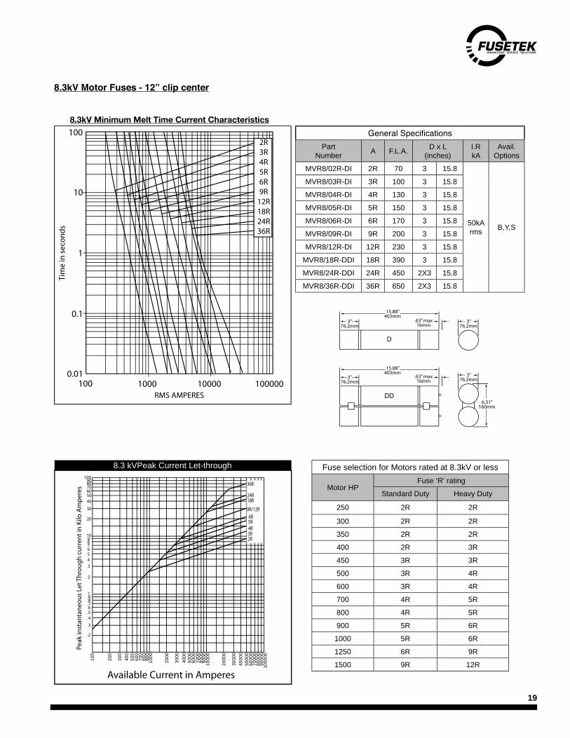
8.3kV Motor Fuses - 12” clip center
General SpecificationsPart
Number A F.L.A. D x L(inches)
I.RkA
Avail.Options
MVR8/02R-DI 2R 70 3 15.8
50kArms B,Y,S
MVR8/03R-DI 3R 100 3 15.8MVR8/04R-DI 4R 130 3 15.8MVR8/05R-DI 5R 150 3 15.8MVR8/06R-DI 6R 170 3 15.8MVR8/09R-DI 9R 200 3 15.8MVR8/12R-DI 12R 230 3 15.8
MVR8/18R-DDI 18R 390 3 15.8MVR8/24R-DDI 24R 450 2X3 15.8MVR8/36R-DDI 36R 650 2X3 15.8
Fuse selection for Motors rated at 8.3kV or less
Motor HPFuse ‘R’ rating
Standard Duty Heavy Duty
250 2R 2R
300 2R 2R350 2R 2R400 2R 3R450 3R 3R500 3R 4R600 3R 4R700 4R 5R800 4R 5R900 5R 6R1000 5R 6R1250 6R 9R1500 9R 12R
1000.01
0.1
1
10
100
1000 10000 100000
2R3R4R5R6R9R
12R18R24R36R
RMS AMPERES
Tim
e in
sec
on
ds
8.3 kVPeak Current Let-through
8.3kV Minimum Melt Time Current Characteristics
8.3kV Peak Current Let-through
Available Current in Amperes
Peak
inst
anta
neou
s Le
t Thr
ough
cur
rent
in K
ilo A
mpe
res 36R
24R18R
9R/12R6R5R4R3R2R
.2
.3
.4
.5
.6
.7
.8
.91
2
345678910
20
30
405060708090
100
100
200
300
400
500
600
700
800
900
1000
2000
3000
4000
5000
6000
7000
8000
9000
1000
0
3000
0
2000
0
4000
050
000
6000
070
000
8000
090
000
1000
00
15.88”403mm
15.88”403mm
3”76.2mm
3”76.2mm
.63” max16mm
3”76.2mm
.63” max16mm
6.31” 160mm
3”76.2mm
D
DD

20
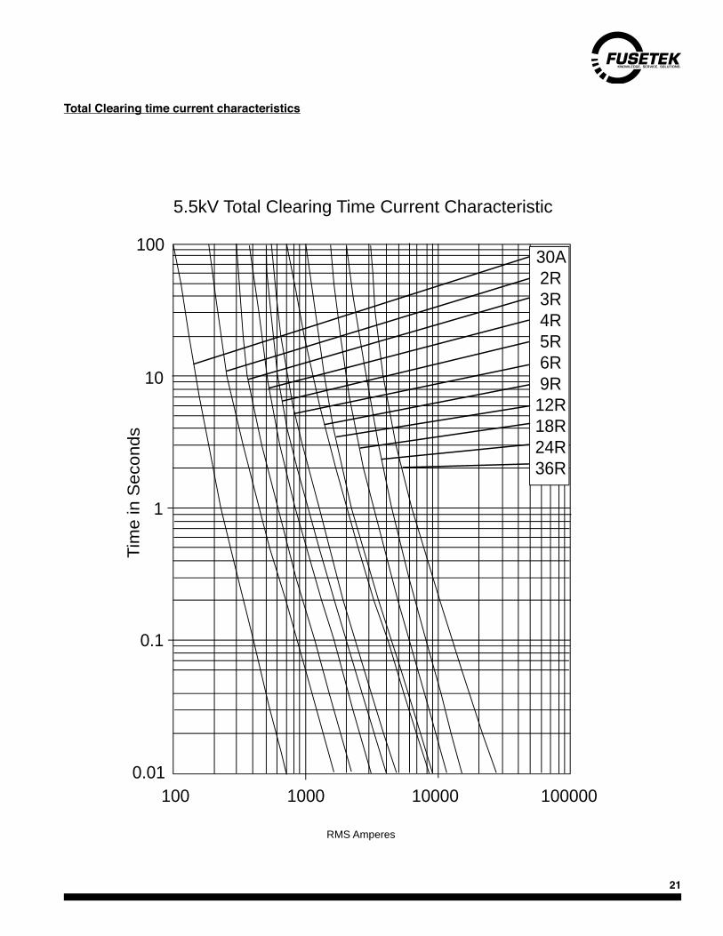
Total Clearing time current characteristics
These time current curves have been plotted to maximum test points so any variations should be negative. Curves are based on tests at an ambient of 25 C with fuses starting from cold with no initial load.
Tim
e in
Sec
onds
25A2R3R4R5R6R9R
12R18R24R
2.75kV Total Clearing Time Current Characteristics
0.01
0.1
10
100
1
100 1000 10000 100000RMS Amperes
2.75kV Total Clearing Time Current Characteristic
o
21
Total Clearing time current characteristics
0.01
0.1
10
100
1
Tim
e in
Sec
onds
100 1000 10000 100000
30A2R3R4R5R6R9R
12R18R24R36R
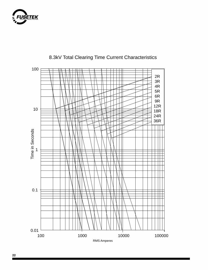
5.5kV Total Clearing Time Current Characteristics
RMS Amperes
5.5kV Total Clearing Time Current Characteristic
RMS Amperes
22
RMS Amperes100
0.01
0.1
10
100
1
1000 10000 100000
8.3kV Total Clearing Time Current Characteristics
2R3R4R5R6R9R
12R18R24R36R
Tim
e in
Sec
onds

23
MVR Dimensions - Standard
15.88”403mm
17.8”457mm
19.3”490mm
3”76.2mm
3”76.2mm
.44” X .91” Slots(1.53” c.t.c.)
3”76.2mm
.63” max16mm
.63” max16mm
3”76.2mm
3.6”91.4mm
7.6”193mm
Front view
MVR Dimensions - ‘B’ bolt-in
Dimensions - GE TagsDimensions for GE tags are dictated by the GE starters they fit into.
15.88”403mm
15.88”403mm
3”76.2mm
3”76.2mm
.63” max16mm
3”76.2mm
.63” max16mm
6.31” 160mm
3”76.2mm
D
DD

24
Features
n General purpose 'E' rated characteristics.n Pure silver elementsn Fully plated metal parts for cool running.n Excellent current limitation for substantial reduction of short circuit stresses.n Blown fuse indicator pin for visual indication or mechanical actuation (except 2" body)n All D Case 3" Diameter fuses can be hermetically sealed and supplied without indicator for use in hazardous location application.
Companion Products
Standoff insulators, fuse clips and bases. Please see accessories section in rear of this section. For other ratings and designs, please contact Fusetek.
Retrofitting
Fusetek power fuses are dimensionally compatible with and interchangeable with other manufacturers' fuses having the same dimensions and ratings. Standard 'E' rated characteristics ensure electrical equivalency.
Fuses should be replaced in sets of three to avoid nuisance blowing caused by element damage.
Tag Variations
3" diameter E rated fuses are available with the following options. Add the suffixes shown to the end of the part number - example;
X - 2" longer tube to line up with some manufacturers' longer bodies.Bi - Offset mounting brackets for bolt mounting.W - Hookeye disconnect feature.CL - ITE/Gould style clip-lock mounting.
E Rating Defined
100E or less:Fuse must open in 300sec at 200-240% of its rated current over 100E: Fuse must open in 600sec. at 220-264% of its rated current.
Thus, fuses with identical E ratings will provide similar overload protection and co-ordination with transformer and other protective devices.
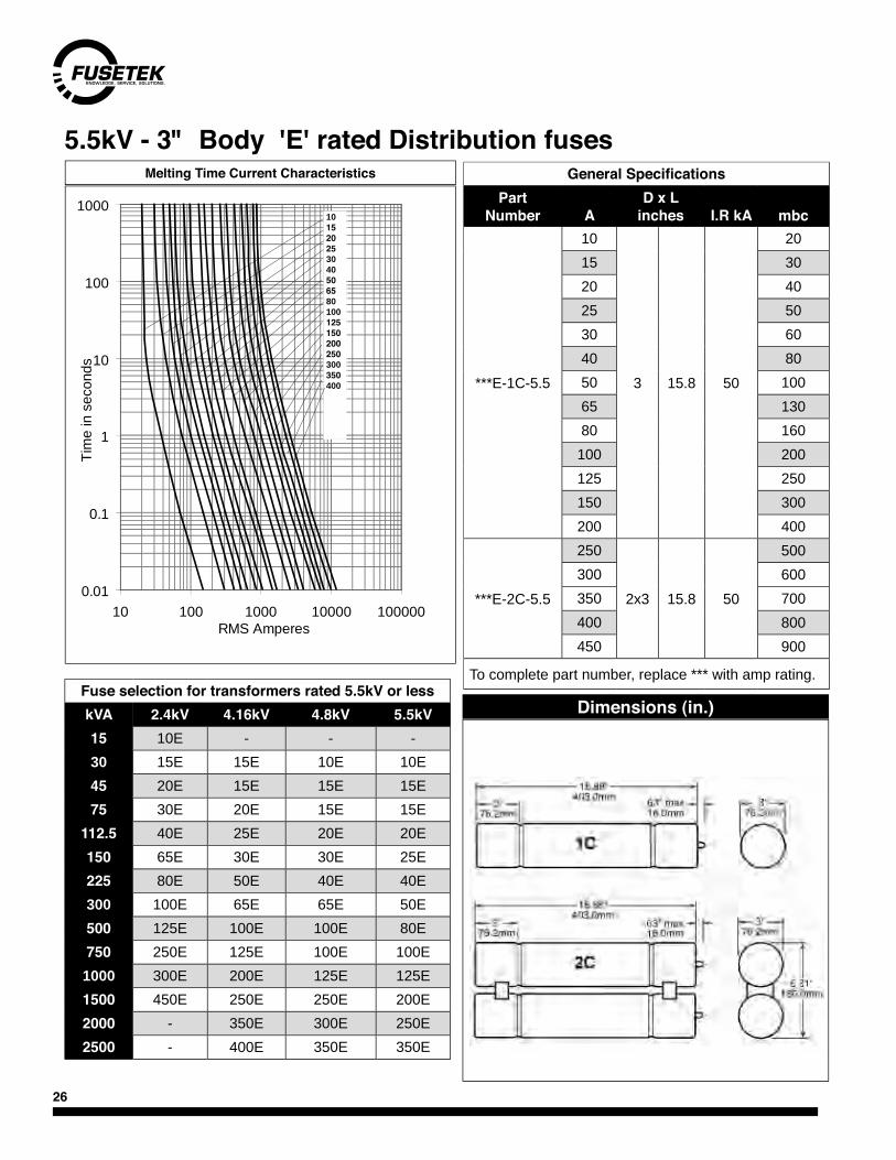
E Rated Distribution fusesE rated power fuses are current limiting partial-range fuses usually used for fusing the primary windings of medium voltage distribution transformers and associated distribution circuits.
Their high degree of current limitation greatly reduces the thermal and mechanical stresses imposed on system components during a short circuit. They can be used indoors or outdoors in a suitable enclosure and conform to standard N. American dimensions.

25
“3" Format (D diam.) Dimensions
Ratings AvailableI.R
Vac Type L CC Fig. Part Number rms sym.
2.4/2.75kVD 10.8 7.0 1 ***E-1C-2.75 10, 15, 20, 25, 30, 40, 50, 65, 80, 100,
125, 150, 175, 200E50kA
DD 10.8 7.0 2 ***-2C-2.75 125, 150, 175, 200, 225, 250, 300, 350, 400, 450E
4.8/5.5kV
D15.8 12.0
1***-1C-5.5
10, 15, 20, 25, 30, 40, 50, 65, 80, 100, 125, 150, 175, 200E
50kA
17.8 14.0 5NLE-***D-ITE 4 ***-1CL-5.5
DD15.8 12.0
2***-2C-5.5 150, 200, 225, 250, 300, 350, 400,
450E17.8 14.0 5NLE2-***
7.2/8.3kVD
15.8 12.01
***-1C-8.310, 15, 20, 25, 30, 40, 50, 65, 80, 100E 50kA
17.8 14.0 8NLE-***
DD15.8 12.0
2***-2C-8.3
125, 150, 175 200, 250, 300E 50kA17.8 14.0 8NLE2-***
13.8/15.5kV
D18.8 15.0
1***-1C-15.5
10, 15, 20, 25, 30, 40, 50, 65, 80, 100E
37.5kA
21.8 18.0 15GSE-***23.8 20.0 15NLE-***
D-ITE 4 ***-1CL-15.5
DD18.8 15.0
2***-2C-15.5
65, 80, 100, 125, 150, 175, 200E21.8 18.0 15GSE2-***23.8 20.0 15NLE-***
23/25.8kVD 24.5 21.0 1 ***-1C-25.8 15, 20, 25, 30, 40, 50E
25kADD 2 ***-2C-25.8 65, 80, 100E
30/38kVD 30.8 27.0 1 ***-1C-38 15, 20, 25, 30, 40E
12.5kADD 2 ***-2C-38 50, 65, 80E
Fig. 1 Fig. 2 Fig. 3 Fig. 4
3" Dia. 6.38" 9.75"
DCC
26
Dimensions (in.)Fuse selection for transformers rated 5.5kV or lesskVA 2.4kV 4.16kV 4.8kV 5.5kV15 10E - - -30 15E 15E 10E 10E45 20E 15E 15E 15E75 30E 20E 15E 15E
112.5 40E 25E 20E 20E150 65E 30E 30E 25E225 80E 50E 40E 40E300 100E 65E 65E 50E500 125E 100E 100E 80E750 250E 125E 100E 100E1000 300E 200E 125E 125E1500 450E 250E 250E 200E2000 - 350E 300E 250E2500 - 400E 350E 350E
General SpecificationsPart
Number
AD x L
inches I.R kA mbc
***E-1C-5.5
10
3 15.8 50
2015 3020 4025 5030 6040 8050 10065 13080 160100 200125 250150 300200 400
***E-2C-5.5
250
2x3 15.8 50
500300 600350 700400 800450 900
To complete part number, replace *** with amp rating.
5.5kV - 3" Body 'E' rated Distribution fusesMelting Time Current Characteristics
0.01
0.1
1
10
100
1000
10 100 1000 10000 100000RMS Amperes
Tim
e in
sec
onds
101520253040506580100125150200250300350400

27
8.3kV - 3" Body 'E' rated Distribution fuses
General SpecificationsPart
Number A D x L (inch)
I.R kA mbc A
total I2t
x1000
***E-1C-8.25
10
3 15.8 50
22.5 .2515 35 .4020 50 .6525 60 .9030 70 1.340 90 2.050 125 3.065 150 4.080 190 6.0100 240 8.5
***E-2C-8.3
125
2x3 15.8 50
300 12.5150 360 18.0200 480 28.0250 600 37.0300 720 50.0
***E-3C-8.3 350 3x3 15.8 50 840 65.0400 960 80.0
kVA 5.5kV 6.9kV 7.2kV 8.3kV45 10E 10E 10E -75 15E 15E 15E -
112.5 20E 15E 15E 10E150 25E 20E 20E 15E225 40E 30E 30E 20E300 40E 40E 40E 30E500 80E 65E 65E 50E750 100E 100E 100E 80E1000 125E 100E 100E 100E1500 200E 150E 150E 150E2000 250E 200E 200E 200E2500 350E 250E 250E 250E3000 400E 350E 350E 300E3500 - 350E 350E 350E4000 - - 400E 350E
Dimensions (in.)Fuse selection for transformers rated 8.3kV or less
0.01
0.1
1
10
100
1000
10 100 1000 10000 100000RMS Amperes
Tim
e in
sec
onds
101520253040506580100125150200250300350400
Melting Time Current Characteristics
To complete part number, replace *** with amp rating.
28
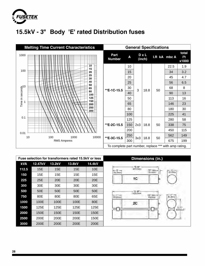
15.5kV - 3" Body 'E' rated Distribution fuses
General Specifications
Part Number A D x L
(inch) I.R kA mbc Atotal
I2t x1000
**E-1C-15.5
10
3 18.8 50
22.5 1.915 34 3.220 45 4.725 56 6.530 68 840 90 1350 113 1665 146 2380 180 30100 225 41
**E-2C-15.5125
2x3 18.8 50280 58
150 338 75200 450 115
**E-3C-15.5250
3x3 18.8 50562 149
300 675 199To complete part number, replace *** with amp rating.
Melting Time Current Characteristics
Fuse selection for transformers rated 15.5kV or lesskVA 12.47kV 13.2kV 13.8kV 14.4kV
112.5 15E 15E 15E 10E150 15E 15E 15E 15E225 25E 20E 20E 20E300 30E 30E 30E 30E500 50E 50E 50E 50E750 80E 80E 80E 65E
1000 100E 100E 100E 80E1500 125E 125E 125E 125E2000 150E 150E 150E 150E2500 200E 200E 200E 150E3000 200E 200E 200E 200E
Dimensions (in.)
0.01
0.1
1
10
100
1000
10 100 1000 10000RMS Amperes
Tim
e in
sec
onds
101520253040506580100125150200250300
29
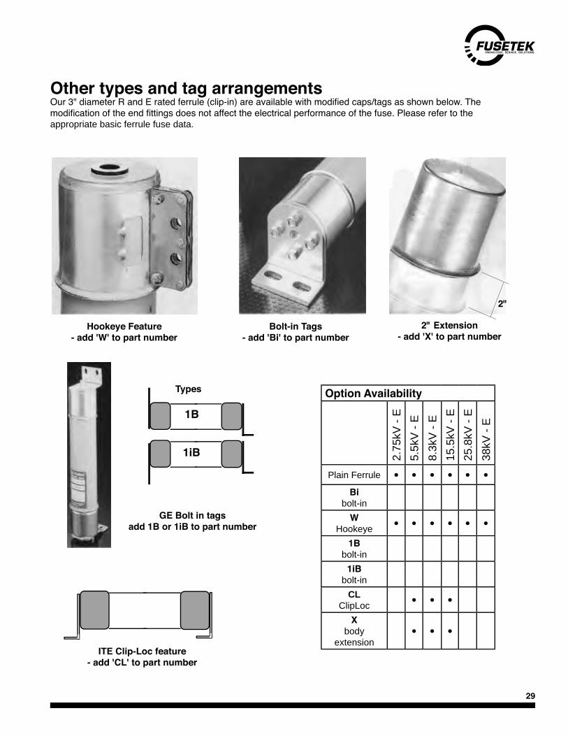
Other types and tag arrangementsOur 3" diameter R and E rated ferrule (clip-in) are available with modified caps/tags as shown below. The modification of the end fittings does not affect the electrical performance of the fuse. Please refer to the appropriate basic ferrule fuse data.
Hookeye Feature - add 'W' to part number
2" Extension - add 'X' to part number
Bolt-in Tags - add 'Bi' to part number
GE Bolt in tagsadd 1B or 1iB to part number
1B
1iB
2"
ITE Clip-Loc feature - add 'CL' to part number
Types Option Availability2.
75kV
- E
5.5k
V - E
8.3k
V - E
15.5
kV -
E25
.8kV
- E
38kV
- E
Plain Ferrule • • • • • •Bi
bolt-inW
Hookeye • • • • • •1B
bolt-in1iB
bolt-inCL
ClipLoc • • •X
body extension
• • •
30
Retrofitting
Fusetek PT fuses can replace any other manufacturers' PT fuse with same dimensions and voltage/amp rating. When replacing fuses, ensure that fuse clips still have good spring tension. Adjust or replace if necessary. Make sure contact surfaces are clean and free of corrosion.
Companion Products
Insulators, fuse clips and bases. Please see the end of this section for these items.
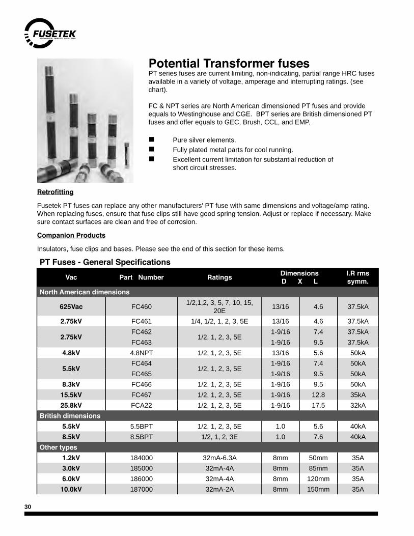
Potential Transformer fusesPT series fuses are current limiting, non-indicating, partial range HRC fuses available in a variety of voltage, amperage and interrupting ratings. (see chart).
FC & NPT series are North American dimensioned PT fuses and provide equals to Westinghouse and CGE. BPT series are British dimensioned PT fuses and offer equals to GEC, Brush, CCL, and EMP.
n Pure silver elements.n Fully plated metal parts for cool running.n Excellent current limitation for substantial reduction of short circuit stresses.
PT Fuses - General Specifications
Vac Part Number Ratings DimensionsD X L
I.R rms symm.
North American dimensions
625Vac FC460 1/2,1,2, 3, 5, 7, 10, 15, 20E 13/16 4.6 37.5kA
2.75kV FC461 1/4, 1/2, 1, 2, 3, 5E 13/16 4.6 37.5kA
2.75kVFC462
1/2, 1, 2, 3, 5E1-9/16 7.4 37.5kA
FC463 1-9/16 9.5 37.5kA4.8kV 4.8NPT 1/2, 1, 2, 3, 5E 13/16 5.6 50kA
5.5kVFC464
1/2, 1, 2, 3, 5E1-9/16 7.4 50kA
FC465 1-9/16 9.5 50kA8.3kV FC466 1/2, 1, 2, 3, 5E 1-9/16 9.5 50kA
15.5kV FC467 1/2, 1, 2, 3, 5E 1-9/16 12.8 35kA25.8kV FCA22 1/2, 1, 2, 3, 5E 1-9/16 17.5 32kA
British dimensions5.5kV 5.5BPT 1/2, 1, 2, 3, 5E 1.0 5.6 40kA8.5kV 8.5BPT 1/2, 1, 2, 3E 1.0 7.6 40kA
Other types1.2kV 184000 32mA-6.3A 8mm 50mm 35A3.0kV 185000 32mA-4A 8mm 85mm 35A6.0kV 186000 32mA-4A 8mm 120mm 35A
10.0kV 187000 32mA-2A 8mm 150mm 35A
31
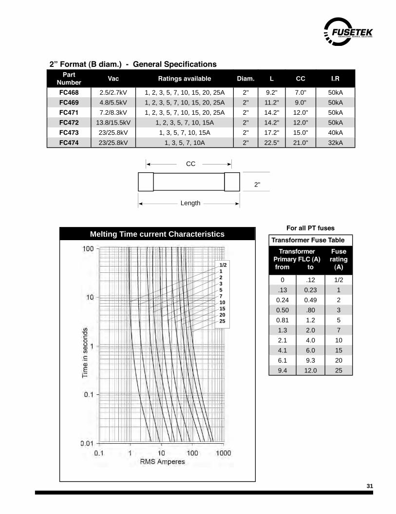
Transformer Fuse TableTransformer
Primary FLC (A) from to
Fuse rating
(A)
0 .12 1/2.13 0.23 1
0.24 0.49 20.50 .80 30.81 1.2 51.3 2.0 72.1 4.0 104.1 6.0 156.1 9.3 209.4 12.0 25
2” Format (B diam.) - General SpecificationsPart
Number Vac Ratings available Diam. L CC I.R
FC468 2.5/2.7kV 1, 2, 3, 5, 7, 10, 15, 20, 25A 2" 9.2" 7.0" 50kAFC469 4.8/5.5kV 1, 2, 3, 5, 7, 10, 15, 20, 25A 2" 11.2" 9.0" 50kAFC471 7.2/8.3kV 1, 2, 3, 5, 7, 10, 15, 20, 25A 2" 14.2" 12.0" 50kAFC472 13.8/15.5kV 1, 2, 3, 5, 7, 10, 15A 2" 14.2" 12.0" 50kAFC473 23/25.8kV 1, 3, 5, 7, 10, 15A 2" 17.2" 15.0" 40kAFC474 23/25.8kV 1, 3, 5, 7, 10A 2" 22.5" 21.0" 32kA
Length
CC
For all PT fuses
2"
Melting Time current Characteristics
1/21235710152025
Melting Time current Characteristics
32
DIN HV DistributionDIN HV fuses are partial-range high voltage current-limiting fuses for use in distribution circuits from 2.3 - 38kV.
Their compact dimensions and non-venting characteristics make them ideal for restricted enclosures. DIN HV fuses have excellent short circuit performance and good low overcurrent clearing capability. When used in combination with fusible switches with fuse-activated trip feature, full range clearing capability is achieved.
True full-range fuses are available in certain voltage and amp ranges. Please contact Fusetek for more information.
Features
n Highly standardised DIN 43 625 dimensions.n Excellent short circuit performance. Ceramic bodies, pure silver elements.n '30' series fuses have a temperature sensitive striker to protect against extended overload conditions, or
external overheating. n Sealed for indoor or outdoor use. n Striker pin can be used for visual indication or mechanical actuation of other devices. (Std-80N, HD - 120N)n High amp ratings available for larger installations. n Fully plated parts for cool running.
Installation Notes
1. DIN fuses are partial range devices with a minimum interrupting rating. Care must be taken to ensure thatanticipated currents below the fuse's minimum breaking current (m.b.c) are cleared by other devices. In thisregard, DIN fuses are similar to ANSI - 'E' rated fuses. Full range DIN fuses are available in limited voltageand amp ranges. Please contact Fusetek for information.
2. When DIN fuses are used in conjunction with a trip-all-phase-device, the minimum breaking capacity of the switch or contactor must be equal to or greater than the m.b.c of the fuse.
3. Maximum voltages listed are absolute maximums for safe operation. Utility system tolerances on voltagemust be considered when selecting a voltage range.
4. When replacing fuses in the field, ensure that contact clips are clean and free of corrosion, dirt, grease etc. Ensure that the fuse clips still have good tension. (if the fuse will spin easily in the fuse clips, the clips havelost their tension and should be replaced)
5. Fuses should be replaced in sets of three to avoid nuisance blowing caused by element damage.

33
Dimensions
All DIN fuse share common end fittings which fit into 45mm fuse clips. The only dimensional variables are the body length (L) and body diameter (D). As this varies depending on voltage, amperage and other factors, please refer to the tables in this section for D and L dimensions. Striker pins meet industry and DIN requirements for force/travel and can be used for mechanical actuation or visual indication.
Transformer application
The fuse ratings recommended in the following tables have been chosen with the following conditions in mind:
n Fuses must pass normal primary winding magnetising inrush currents: These are taken as 12x the normal full load current (FLC) at .1 sec, and 25x FLC at .01 sec. Certain applications may require the use of a higher fuse rating. Please contact FUSETEK with application details.n After a sustained power outage, the fuse must be able to withstand an overload of approximately 6 x FLC for 1 sec. and 3 x FLC for 10 sec.n The maximum voltage rating of the fuse must be equal to, or greater than the maximum line-to-line system voltage.
Capacitor application
Refer to capacitor selection chart on page 27. Be sure to consider the switching options and proximity of other banks when establishing a base FLC to apply. Fuses used on Capacitor fuses should be rated at 150% of system voltage.
Companion Products
Insulators, clips, single pole bases
Note: I2t and interrupting ratings shown in following tables are at maximum system voltage.
Current cut-off characteristics (all voltage classes)
160A125A100A80A
63A50A
40A31.5A
25A20A
16A
10A6.3A
Prospective Short Circuit Current x 100010¯¹ 10 ⁰ 10 ² 10 ³10 ¹
10 ⁰
10 ¹
10 ²
10 ³
îc(kA)
Cut
Off
Cur
rent
Pea
k
500A355A400A
315A200A
250A
Prospective Short Circuit Current x 1000)10¯¹ 10 ⁰ 10 ² 10 ³10 ¹
10 ⁰
10 ¹
10 ²
10 ³
îc(kA)
Cut
Off
Cur
rent
Pea
k
34
3.0/7.2kVGeneral Specifications
Part Number A D x L
(mm)I.R kA mbc A
total I2t
x 1000
30 098 13
6.3
53 292 63kA rms
22 0.3710 34 0.5716 56 2.020 70 4.925 90 7.8
31.5 110 10.340 140 19.550 170 34
30 099 13
63
67 292 63kA rms
210 6980 280 145100 320 210125 390 399
30 100 13 160 85 292 63kA 600 580
30 100 14
200
85 292 50kA rms
800 740250 1000 1200315 1260 1800355 1420 2300
30 110 14400
85 442 50kA rms
1600 2900500 2000 4800
Other body lengths and configurations available. Please contact Fusetek.
Melting Time Current Characteristics
Dimensions (mm)
RMS Amperes
Minimum fuse for transformers rated 7.2kV or lesskVA 2.4kV 4.16kV 4.8kV 6.9kV15 10A 6.3A 6.3A 6.3A30 20A 16A 10A 10A45 20A 16A 16A 16A75 40A 20A 20A 16A
112.5 50A 31.5A 25A 20A150 63A 40A 40A 25A225 80A 63A 50A 40A300 125A 80A 63A 50A500 200A 125A 100A 80A750 250A 160A 160A 100A1000 315A 200A 200A 125A1500 500A 315A 250A 200A2000 - 355A 315A 200A2500 - 500A 355A 250A3000 - - 400A 315A4000 - - - 500A
1000
1000
6.31016202531.540506380100125160200250315355400
100
100
10
1
0.1
0.0110 10,000 100,000
Tim
e in
sec
onds

35
Melting Time Current Characteristics General SpecificationsPart
Number A D x L (mm) I.R kA mbc
Atotal I2t x 1000
30 004 13
6.3
53 292 63kA rms
22 0.3710 34 0.5716 56 2.020 70 4.925 90 7.8
31.5 110 10.340 140 19.550 170 34
30 012 13
63
67 292 63kA rm
210 6980 280 145100 320 210125 390 399
30 020 13 160 85 292 63kA 600 58030 020 14 200 85 292 50kA 800 74030 211 14 250 85 537 50kA
rms1000 1100
30 211 14 315 85 537 1260 1800
Other body lengths and configurations available. Please contact Fusetek.
0.01
0.1
1
10
100
1000
10 100 1000 10000RMS Amperes
Tim
e in
sec
onds
6/12kV
Minimum fuse for transformers rated 12kV or lesskVA 6.9kV 7.2kV 8.3kV 12kV15 6.3A 6.3A 6.3A 6.3A30 10A 6.3A 6.3A 6.3A45 16A 10A 10A 6.3A75 16A 16A 16A 10A
112.5 20A 20A 20A 16A150 25A 25A 25A 20A225 40A 40A 25A 20A300 50A 50A 31.5A 25A500 80A 80A 63A 50A750 100A 100A 80A 63A
1000 125A 125A 100A 80A1500 200A 200A 160A 125A2000 200A 200A 160A 160A2500 250A 250A 250A 200A3000 315A 315A 315A 200A4000 see 7.2kV class - 250A
Dimensions (mm)
6.31016202531.540506380100125160200250315

36
Melting Time Current Characteristics General SpecificationsPart
Number A D x L (mm)
I.R kA
mbc A
total I2t x 1000
30 231 13
6.3
53 442 63kA rms
22 0.3710 34 0.5716 56 2.020 70 4.925 90 7.8
31.5 110 10.340 140 19.5
30 232 1350
67 442 63kA rms
170 3463 210 6980 280 145
30 233 13100
85 442 63kA rms
320 210125 390 399160 600 300
30 233 14 200 85 442 40kA 800 590DRS15/250B8 250
2x 85
442 40kA rms
375 1000DRS15/315B8 315 442 480 2000DRS15/400B8 400 442 20kA 800 4000
Other body lengths and configurations available. Please contact Fusetek.
0.01
0.1
1
10
100
1000
10 100 1000 10000 100000RMS Amperes
Tim
e in
sec
onds
10/17.5kV
Minimum fuse for transformers rated 17.5kV or lesskVA 12.47kV 13.2kV 13.8kV 14.4kV45 6.3A 6.3A 6.3A 6.3A75 10A 10A 10A 6.3A
112.5 16A 16A 16A 10A150 20A 16A 16A 16A225 20A 20A 20A 20A300 25A 25A 25A 20A500 50A 50A 40A 31.5A750 63A 63A 63A 50A1000 80A 80A 80A 63A1500 125A 100A 100A 80A2000 160A 160A 125A 100A2500 200A 160A 160A 125A3000 200A 200A 200A 200A4000 250A 250A 200A 250A5000 315A 315A 315A 315A6000 400A 400A 400A 315A7000 - 400A 400A -
Dimensions (mm)
6.31016202531.540506380100125160200250315400

37
20/27.6kV
6.31016202531.540506380100125
Melting Time Current Characteristics General SpecificationsPart
Number A D x L (mm)
I.R kA
mbc A
total I2t x 1000
30 289 13 6.3 53 44240kA rms
22 .2630 289 13 10 53 442 34 .5630 289 13 16 53 442 56 2.0
30 288 13
20
67 442 40kA rms
70 5.025 90 7.8
31.5 110 12.040 140 20.050 170 33.563 210 69
30 287 1380
85 442 40kA rms
280 145100 320 210125 390 399
Other body lengths and configurations available. Please contact Fusetek.
Fuse selection for transformers rated 25.8kV or lesskVA 17kV 23kV 24kV 25.8kV
112.5 16A 10A 10A 10A150 16A 10A 10A 10A225 20A 16A 16A 16A300 20A 20A 20A 16A500 31.5A 25A 25A 25A750 50A 40A 40A 31.5A
1000 63A 50A 50A 50A1500 80A 63A 63A 63A2000 100A 80A 80A 80A2500 125A 100A 100A 100A3000 160A 125A 125A 100A
Dimensions (mm)
RMS Amperes
Tim
e in
sec
onds
38
Melting Time Current Characteristics General SpecificationsPart
Number A D x L (mm)
I.R kA
mbc A
total I2t x 1000
30 008 13
6.3
53 537 40kA rms
22 0.3710 34 0.5716 56 2.020 70 4.925 90 7.8
30 016 1331.5
67 537 40kA rms
110 10.340 140 19.5
30 024 13
5085 537 40kA
rms170 34
63 210 6980
85 537 40ka rms
280 145100 320 210
DRS30/125A9 125 2x 66 537 16kA 158 140
DRS30/150B9 150 2x 85 537 20kA
rms225 200
DRS30/200B9 200 300 580
Other body lengths and configurations available.
0.01
0.1
1
10
100
1000
10 100 1000 10000
RMS Amperes
Tim
e in
sec
onds
20/36kV
Dimensions (in.)Fuse selection for transformers rated 36kV or lesskVA 25.8kV 27.6kV 34.5kV 36kV
112.5 10A 6.3A 6.3A 6.3A150 10A 10A 10A 6.3A225 16A 16A 10A 10A300 16A 16A 16A 16A500 25A 20A 16A 20A750 31.5A 31.5A 25A 25A1000 50A 40A 31.5A 31.5A1500 63A 63A 50A 50A2000 80A 80A 63A 63A2500 100A 80A 80A 80A3000 100A 100A 80A 80A4000 160A 125A 100A 100A5000 200A 160A 125A 125A6000 200A 200A 125A 160A7000 - 200A 160A 160A10000 - - - -
6.31016202531.540506380100125150200
39
Fuse selection for transformers rated 38kV or lesskVA 27.6kV 34.5kV 36kV 38kV
112.5 6.3A 6.3A 6.3A 4A150 10A 10A 6.3A 6.3A225 16A 10A 10A 10A300 16A 16A 16A 16A500 20A 16A 20A 20A750 31.5A 25A 25A 25A1000 40A 31.5A 31.5A 31.5A1500 63A 50A 50A 50A2000 - 63A 63A 63A2500 - - - 63A
38.5kVMelting Time Current Characteristics General Specifications
Part Number A D x L
(mm)I.R kA
mbc A
total I2t x 1000
6.353 537 40kA
22 36010 34 560
30 338 13
1667
537
40kA
56 200020 70 480025 90 7500
31.5 110 12000
30 339 1340
85 537 40kA140 19000
50 170 3300063 210 66000
0.01
0.1
1
10
100
1000
1 10 100 1000 10000RMS Amperes
Tim
e in
sec
onds
6.31016202531.5405063
Dimensions (mm)
40
HV - 200A DIN fuse basesSIBA single pole fuse bases are designed for indoor use and will accept standard DIN 43625 fuses.
Channel base is heavy duty zinc plated steel with epoxy resin standoff insulators and grounding provision.
Standard 200A clips are nickel plated with backup spring. 400A clips are optional.
These bases are available in outdoor versions also. Please contact Fusetek.
p/n 31 001 02 p/n 31 003 02 p/n 31 005 02 p/n 31 007 02max Voltage 7.2kV 12kV 24kV 36kVClip rating 200A 200A 200A 200A
DIN fuse length 192mm 292mm 442mm 537mmDimensions - in. (mm)
BL 12.20 (310mm) 16.14 (410mm) 22.60 (574mm) 26.60 (676mm)
CC 2.17 (55mm) 7.10 (180mm) 11.80 (300mm) 14.96 (380mm)
H 0.60’ (15mm) 0.60’ (15mm) 0.60’ (15mm) 0.60’ (15mm)FC 13.78 (350mm) 17.72 (450mm) 23.62 (600mm) 27.36 (695mm)FL 7.60 (193mm) 11.54 (293mm) 17.44 (443mm) 21.18 (538mm)HT 9.53 (242mm) 9.63 (242mm) 12.68 (322mm) 16.22 (412mm)HC 6.14 (156mm) 6.14 (156mm) 9.30 (236mm) 12.83 (326mm)TL 14.96 (380mm) 18.9 (480mm) 24.8 (630mm) 28.54 (725mm)W 3.35 (85mm) 3.35 (85mm) 3.35 (85mm) 3.35 (85mm)W2 1.38 (35mm) 1.38 (35mm) 1.38 (35mm) 1.38 (35mm)
41
Application
Please refer to the fuse selection chart on page 27 of this publication.
Ratings: 25, 50, 75, 100, 125 Vac: 25 - 75A 4.8kV 100 - 125A 2.4kVI.R: 50kA rms symm m.b.c 200% of ratingApprovals: designed in accordance with ANSI 47.40
TCCF 2.4/4.8kV Capacitor fusesTCCF fuses are current-limiting, partial range fuses designed for the individual unit fusing of three phase capacitors in metal enclosed equipment. They are non-indicating and non-disconnecting.
n Direct stud-mounting on 1/2-13 capacitor studs eliminates separate holder.n replaces Westinghouse, GE and some McGraw fuses n Adapters are available to convert to other stud threadsn Add "B" suffix for M12 boss at one end and 1/2-13 boss at other end.
185
20
20
50
Stud1/2-13unc
25hex
Boss1/2-13uncinternal
p/n example TCCF- 50B
Dimensions (mm)
225
Note:Add "B" suffix for M12 Boss at one end &1/2-13 boss at other end.
p/n example TCCF- 50
TCCF Average melt time current curves
25A50A75A
100A125A
1000
1000
100
100
10
1
0.1
0.0110 10,000
RMS Amperes
Tim
e in
sec
onds

42
SIBA 600V Capacitor fusesSIBA capacitor fuses offer increased voltage and amp ratings for larger capacitor applications. They feature ceramic bodies and higher interrupting ratings. Imperial UNC thread pattern is standard. Metric styles also available.
Rated VoltageAC 4.8kV
ClassBack up
Thread1/2” UNC
Standard IEC 60 282-1 - IEC 60 549
RatedCurrent
Part No. D= Diameterinch mm
Rated BreakingCapacity kA
Weight(kg/1)
Pack
6.3A 30 349 21.6.3 2.5 63.5 63 1.8 110A 30 349 21.10 2.5 63.5 63 1.8 116A 30 349 21.16 2.5 63.5 63 1.8 120A 30 349 21.20 2.5 63.5 63 1.8 125A 30 349 21.25 2.5 63.5 63 1.8 1
31.5A 30 349 21.31.5 2.5 63.5 63 1.8 140A 30 349 21.40 2.5 63.5 63 1.8 150A 30 349 21.50 2.5 63.5 63 1.8 163A 30 349 21.63 2.5 63.5 63 1.8 180A 30 349 21.80 2.5 63.5 63 1.8 1
100A 30 349 21.100 2.5 63.5 63 1.8 1125A 30 350 21.125 2.99 76 63 2.5 1160A 30 350 21.160 2.99 76 63 2.5 1200A 30 351 21.200 2.99 76 63 3.6 1250A 30 351 21.250 2.99 76 63 3.6 1
Rated VoltageAC 7.2kV
ClassBack up
Thread1/2” UNC
Standard IEC 60 282-1 - IEC 60 549
RatedCurrent
Part No. D= Diameterinch mm
Rated BreakingCapacity kA
Weight(kg/1)
Pack
6.3A 30 352 21.6.3 2.5 63.5 63 1.8 110A 30 352 21.10 2.5 63.5 63 1.8 116A 30 352 21.16 2.5 63.5 63 1.8 120A 30 352 21.20 2.5 63.5 63 1.8 125A 30 352 21.25 2.5 63.5 63 1.8 1
31.5A 30 352 21.31.5 2.5 63.5 63 1.8 140A 30 352 21.40 2.5 63.5 63 1.8 150A 30 352 21.50 2.5 63.5 63 1.8 163A 30 352 21.63 2.5 63.5 63 1.8 180A 30 352 21.80 2.5 63.5 63 1.8 1
100A 30 352 21.100 2.5 63.5 63 1.8 1125A 30 353 21.125 2.99 76 63 2.5 1160A 30 353 21.160 2.99 76 63 2.5 1200A 30 353 21.200 2.99 76 63 3.6 1
Rated VoltageAC 15.5kV
ClassBack up
Thread1/2” UNC
Standard IEC 60 282-1 - IEC 60 549
RatedCurrent
Part No. D= Diameterinch mm
Rated BreakingCapacity kA
Weight(kg/1)
Pack
6.3A 30 354 21.63 2.5 63.5 63 1.8 110A 30 354 21.10 2.5 63.5 63 1.8 116A 30 354 21.16 2.5 63.5 63 1.8 120A 30 354 21.20 2.5 63.5 63 1.8 125A 30 354 21.25 2.5 63.5 63 1.8 1
31.5A 30 354 21.31.5 2.5 63.5 63 1.8 140A 30 354 21.40 2.5 63.5 63 1.8 150A 30 354 21.50 2.5 63.5 63 1.8 163A 30 354 21.63 2.5 63.5 63 1.8 180A 30 354 21.80 2.5 63.5 63 1.8 1
100A 30 354 21.100 2.5 63.5 63 1.8 1
43
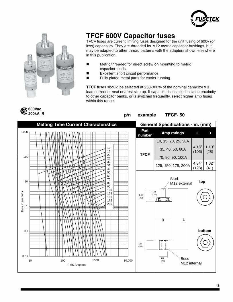
TFCF 600V Capacitor fusesTFCF fuses are current limiting fuses designed for the unit fusing of 600v (or less) capacitors. They are threaded for M12 metric capacitor bushings, but may be adapted to other thread patterns with the adapters shown elsewhere in this publication.
n Metric threaded for direct screw on mounting to metric capacitor studs.n Excellent short circuit performance.n Fully plated metal parts for cooler running.
TFCF fuses should be selected at 250-300% of the nominal capacitor full load current or next nearest size up. If capacitor is installed in close proximity to other capacitor banks, or is switched frequently, select higher amp fuses within this range.
600Vac200kA IR p/n example TFCF- 50
D L
top
bottom
1.18(30)
.78(20)
.85(22)
.78(20)
Stud M12 external
Boss M12 internal
Melting Time Current Characteristics General Specifications - in. (mm)Part
number Amp ratings L D
TFCF
10, 15, 20, 25, 30A
35, 40, 50, 60A 4.13” (105)
1.10”(28)
70, 80, 90, 100A
125, 150, 175, 200A 4.84” (123)
1.62”(41)
101520253035405060708090100125150175200
1000
1000
100
100
10
1
0.1
0.0110 10,000
RMS Amperes
Tim
e in
sec
onds
44
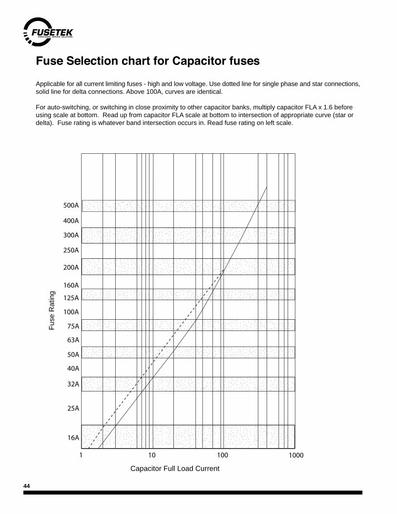
Fuse Selection chart for Capacitor fuses
Applicable for all current limiting fuses - high and low voltage. Use dotted line for single phase and star connections, solid line for delta connections. Above 100A, curves are identical.
For auto-switching, or switching in close proximity to other capacitor banks, multiply capacitor FLA x 1.6 before using scale at bottom. Read up from capacitor FLA scale at bottom to intersection of appropriate curve (star or delta). Fuse rating is whatever band intersection occurs in. Read fuse rating on left scale.
500A
300A
250A
200A
160A
125A
100A
75A
63A
50A
40A
32A
25A
16A
1
400A
10 100 1000
Capacitor Full Load Current
Fuse
Rat
ing

45
>< 23"
Description
Fusetek expulsion links are universal semi-enclosed buttonhead pattern fuse-links for use in standard expulsion distribution cut-outs.
They are available in 'K' (fast) or 'T' (slow) speed and have industry standard, removable button heads. Their braided leads are tin-plated copper and of sufficient length for all standard voltage ratings encountered in the field.
HV Expulsion cut-outfuselinksSpecifications
Voltage Rating: 7.2-34.5kVSpeeds K - fast T - slow
O/L Capacity 150% for both speedsAmp Range: 1-200AApprovals: complies with ANSI/NEMA Ratings: 1, 2, 3, 6, 8, 10, 12, 15, 20, 25, 30, 40, 50, 65, 70, 80, 100, 140, 200A
Part NumbersAmps K Speed T Speed
1 M1KA23 M1TA232 M2KA23 M2TA233 M3KA23 M3TA236 M6KA23 M6TA238 M8KA23 M8TA2310 M10KA23 M10TA2312 M12KA23 M12TA2315 M15KA23 M15TA2320 M20KA23 M20TA2325 M25KA23 M25TA2330 M30KA23 M30TA2340 M40KA23 M40TA2350 M50KA23 M50TA2365 M65KA23 M65TA2380 M80KA23 M80TA23100 M100KA23 M100TA23140 M140KA23 M140TA23200 M200KA23 M200TA23

46
Delle Fuse adapter kitsDelle fuses are now obsolete, but there is a large installed base of fuses that need replacing. Our adapter kits replace the existing Delle live parts and convert the Delle fixing centers to accept a modern, easily obtainable DIN HV fuse.
n Direct bolt-on replacement.n SIBA DIN fuse provide superior protection.n High pressure clips, hardware and conversion plates
Note: Adapter kits consist of 1 pair of 45mm fuse clips, transition plates and hardware. Fuses sold separately. See table above for fuse and adapter kit part numbers. If complete bases are required, please contact Fusetek.
Delle Fuse kV Amp
rangeAdapter
Kit Siba part number Standard DIN Body Comments
**Note: Delle body is 537mm. Ours is 442mm. Clips must be moved to accommodate
shorter body.
FD3 7.2kV6.3 - 50A
Not Required
3009813 - 6.3A to 50A292mm
63 - 125A 3009913 - 63A to 125A
FD4 12kV
6.3 - 50A 3000413 - 6.3A to 50A292mm
63A 3001213 - 63A
80 - 125A 3010213 - 80A to 125A442mm
160A 3010313 - 160A
FD5 17.5kV
6.3 - 40A 3023113 - 6.3A to 40A442mm
50 - 80A 3023213 - 50A to 80A
100 - 125A 3023313 - 100 to 160A 537mm **
FD6 24kV
6.3 - 16A 3028913 - 6.3A to16A442mm
20 - 63A 3028813 - 20A to 63A
80A 3020413 - 80A 537mm
FD7 36kV
6.3 - 25A 3000813 - 6.3A to 25A
537mm32 - 40A 3001613 - 31.5 to 40A
50A 3002413 - 50A

47
DelleFuse kV Amp
rangeAdapter
kit Siba part number Standard DIN body
FLR3 6.6kV 63 - 125A FK101 3009913
292mm5.5kV 160A FK101 3010013
FLR4 10KV 160A FK107 3010313 442mm
FLR5 15kV63 - 80A FK107 3023213
442mm100 - 125A FK107 3023313
FLR7 25kV 63 - 100A FK107 3002413 537mm
FLP25.5kV
160A FK111 3010013
292mm200A FK111 3011014
3.2kV 250A FK111 3010014
FLP3
6.6kV 160A FK105 3011013
442mm6.6kV 200A FK105 3011014
5.5kV 250A FK105 3011014
FLP6 20kV63A FK107 3028813
442mm80 - 100A FK107 3028713
FTR3 6.6kV2 - 10A FK105 3009813
442mm16 - 50A FK101 3009813
FTR4 10kV 40 - 50A FK107 3000413 442mm
FTR5 15kV
2 - 10A FK105 3023113
442mm16 - 32A FK111 3023113
40A FK107 3023113
50A FK107 3023213
FTR6 20kV
2 - 10A FK111 3028913
442mm
16A FK107 3028913
20 - 50A FK107 3028813
16A FK107 3028913
20 - 50A FK107 3028813
FTR7 30kV
2 - 10A FK111 3000813
537mm16 - 25A FK107 3000813
32 - 40A FK107 3001613
50A FK107 3002413
Delle Fuse adapter kits
Obsolete Delle fuses
48
Microswitch Boden Insulated Cable
60
42
12
2.8
37 37590
37 12
10
10.5
4.5
35
8.5
8.4
22
Insulation rating 36kVMax cable length 590mm
Part Number 31 001 10
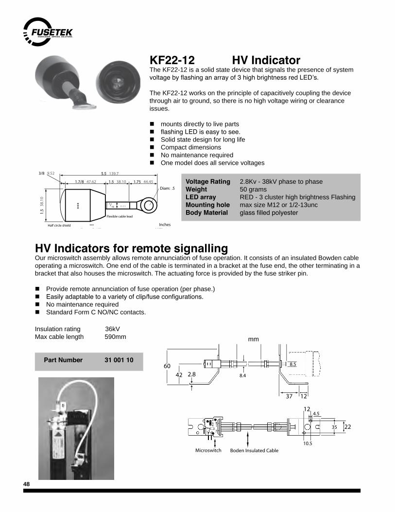
KF22-12 HV IndicatorThe KF22-12 is a solid state device that signals the presence of system voltage by flashing an array of 3 high brightness red LED’s.
The KF22-12 works on the principle of capacitively coupling the device through air to ground, so there is no high voltage wiring or clearance issues.
n mounts directly to live partsn flashing LED is easy to see.n Solid state design for long lifen Compact dimensionsn No maintenance requiredn One model does all service voltages
HV Indicators for remote signallingOur microswitch assembly allows remote annunciation of fuse operation. It consists of an insulated Bowden cable operating a microswitch. One end of the cable is terminated in a bracket at the fuse end, the other terminating in a bracket that also houses the microswitch. The actuating force is provided by the fuse striker pin.
n Provide remote annunciation of fuse operation (per phase.)n Easily adaptable to a variety of clip/fuse configurations.n No maintenance requiredn Standard Form C NO/NC contacts.
***
5.5 139.7
1.75 44.45 1.5 38.10 1.7/8 47.62
1.5
38.
10
InchesMillimeters
3/8 9.52
Half circle shield
Flexible cable lead
***Cluster of 3 LEDsrecessed by 5/8”
Diam: .5 12.7
7/16 11.11
Voltage Rating 2.8Kv - 38kV phase to phaseWeight 50 gramsLED array RED - 3 cluster high brightness FlashingMounting hole max size M12 or 1/2-13uncBody Material glass filled polyester
mm

49
Epoxy resin insulatorsUse our epoxy resin insulators for supporting busbar, mounting hardware or as mechanical standoffs. Rated for indoor use. Cover all popular voltage classes. Bolt pattern is directly compatible with our fuseclips listed at the end of this section.
45mm DIN fuse clipsThe DIN fuse system's best feature is its guaranteed interchangeability. Our 45mm fuse clips will fit any DIN 43 625 HV DIN fuse regardless of origin. In addition, our clips deliver high pressure contacts, a safety backup spring, and bolt directly to our epoxy insulators listed elsewhere. They are available in 200 and 400A variants. The 400A version has a 'hot stick' operable bailing spring.
Bolt pattern for both31 003 02.20 (200A) 3400101.20
Part No. Max kV Cantilever Strength N
Dimensions - mmA B C D E F G
DWA-07A 7.2 4000 100 60 60 1/2 3/8 1/4 115DWA-15A 17.5 4000 165 75 57 5/8 3/8 1/4 230DWA-20A 25.8 4000 210 82 57 5/8 3/8 1/4 290DWA-30A 38.0 4000 300 100 71 5/8 3/8 1/4 430
Part No.31 003 02.20
B 1.26" 32mmG 2.80" 71.5mmH 3.74" 95mm
Part No.34 001 01.20
B 1.26" 32mmG 2.90" 73.5mmH 4.92" 125mm
Bottom & TangA 1.26" 32mmB 1.38" 35mmC 0.24" 6mmD 0.40" 18mmE 0.20" 5mmF 0.70" 18mmG 0.26" 6.5mm
50
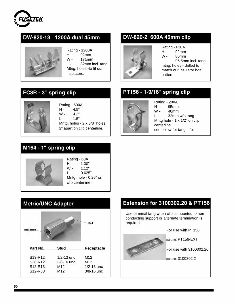
PT156 - 1-9/16" spring clip
Metric/UNC Adapter
Part No. Stud Receptacle
S13-R12 1/2-13 unc M12S38-R12 3/8-16 unc M12S12-R13 M12 1/2-13 uncS12-R38 M12 3/8-16 unc
Rating - 60AH - 1.30"W - 1.12"L - 0.625" Mntg. hole - 0.26" on clip centerline.
DW-820-2 600A 45mm clip
FC3R - 3" spring clip
Rating - 600AH - 4.5"W - 4.3"L - 1.5" Mntg. holes - 2 x 3/8" holes, 2" apart on clip centerline.
DW-820-13 1200A dual 45mm
Rating - 1200AH - 92mmW - 171mmL - 82mm incl. tangMtng. holes -to fit our insulators.
Rating - 630AH - 92mmW - 80mmL - 96.5mm incl. tang mtng. holes - drilled to match our insulator bolt pattern.
Rating - 200AH - 95mmW - 40mmL - 32mm w/o tang Mntg hole - 1 x 1/2" on clip centerline.see below for tang info.
Extension for 3100302.20 & PT156
Use terminal tang when clip is mounted to non conducting support or alternate termination is required.
For use with PT156
part no. PT156-EXT
For use with 3100302.20
part no. 3100302.2
M164 - 1" spring clip
stud
Receptacle

51
British semiconductor fuses (BS88)These fuses are British dimension, ultra fast acting types for the protection of semiconductor devices such as diodes, rectifiers, SCR's, thyristors, etc.
They are used in electronic speed control devices such as soft-starts or inverters, in power conversion equipment, or anywhere where sensitive elec-tronic components need protection.
SIBA UR fuses have excellent energy let-thru characteristics under short circuit conditions.
240Vac
Companion products
LSCR001 and LSCR002 stud mount fuseholders. Refer to Littelfuse PowrGard catalogue.
Part Number Amps
Watts Loss (W)
I2t (A2s) melting total
I.R(rms
symm)
5007606
5 1.5 1.7 9.5
100kA
6 1.7 2.9 1610 3.3 4.2 2412 2.0 8.0 4116 2.4 18 9220 3.3 25 130
5005306
25 3.6 39 260
100kA
32 4.5 40 27035 5.0 63 43040 5.3 100 70050 6.7 130 90063 7.7 250 170075 9.4 330 230080 9.7 420 2900100 12.7 620 4300125 16 1000 6800160 22 1500 10200180 24 2300 15700
5005406
160 23 1300 8000
100kA
200 27 2500 15300250 34 4600 28000315 36 7800 48000355 38 11800 72000400 40 18500 113000450 46 26600 163000
5007106
400 55 10000 61000
100kA
450 56 19000 116000500 59 27000 165000630 62 50000 305000710 72 70000 427000800 74 106000 647000900 90 150000 915000
46mm
38mm27mm
8.4m
m
55mm
40mm26mm
35m
m
84mm
59mm31mm
84mm
59mm31mm
35m
m
78mm
17.5
mm

52
80mm
61mm Part Number Amps
Watts Loss (W)
I2t (A2s)Total
I.R (rms
symm)
NAK
75 9 2300
100kA100 10 4300125 14 6800140 18 7200160 20 10200
690Vac
250Vac (Kyosan equals)
PartNumber
Watts Loss (W)
I2t (A2s) I.R (rms
symm)melting total
5007706
6 3.2 3 20
100kA10 3.7 8 5312 3.9 11 7716 5.5 18 12020 7.5 32 215
5007306
25 7 25 110
100kA
32 9 50 21035 10 60 26040 11 80 33050 12 190 78063 15 290 120080 18 420 1700100 23 740 3100
5007406
100 22 1000 6500
100kA
125 29 1700 11000160 30 4000 26000200 31 9000 58000250 40 18000 116000315 44 27000 173000355 56 36000 231000
5007506
315 48 18500 119000
100kA
355 55 22300 143000400 58 26100 167000450 63 52300 335000500 68 70100 449000630 87 106000 679000710 104 145000 928000
2055920
32 8 52 290
600V300kA
700V200kA
35 9 66 36040 10 90 50050 12 140 77063 14 250 140080 18 470 2600100 22 730 4000125 26 1300 7200160 21 2800 15400180 35 3700 20400200 39 4500 25000250 47 8000 44000315 58 14000 77000
35m
m
105mm
80mm52mm
17m
m
29mm
73mm
64mm54mm
8.4m
m
77mm
63mm48mm
17.5
mm
78mm
105mm
80mm52mm
35m
m
23.5mm
94mm70mm
32mm
54mm

53
Type D Bottle fuses General SpecificationsSize Part
NumberAmp
Range D x L (mm) Speed Vac I.R kA
D01 1002704 2-16A 11 36 gL 380V
100
D02 1002804 20-63A 15 36 gL 380VD03 1002904 80-100A 22 43 gL 380VND 1000204 2-25A 13 50 gT 500V
DIID27-50 2-30A 22 50 gT 500V
GD27-50 2-30A 22 50 gR 500V
DIIID27-50 35-63A 28 50 gT 500V
GD33-50 35-63A 28 50 gR 500V
DIII 1001101 2 - 63A 28 70 gG 750V
Ratings Available: 2, 4, 6, 10, 16, 20, 25, 35, 50, 63A
EurofusesEuropean fuses are used in imported equipment, or in projects destined overseas. Eurofuses are available in two broad categories - bottle fuses and square body fuses. Both categories have many different types within the group. See the individual tables. All European fuses are current and energy limiting.
n Higher voltage rating insures compatible with Canadian voltage levels.n Interchangeable with all imported makes.n Built in blown fuse indicator.n Current and energy limiting.
The following operating classifications are used for these fuses;
gL, gG, General purpose characteristic for distributionaM Back up characteristic for motor circuitsgR Ultrafast characteristic for semiconductor circuits.
L
D
Accessories for bottle fuses Part Numbers
Size Thread pattern
Amp Rat-ing Base Cap Adapter
ScrewInsulating
RingND E13 25 - - - -DII E17 25 30DB27 30DT27 DP27 30DA27DIII E33 63 63DB33 63DT33 DP33 63DA33
Cap
Base Adapter Screw
Cap
Base
Ring (supplied with base)

54
‘NH’ Eurofuses Size Taille
speed vitesse
Part number Amperes Vac kA
DIN 43 620
‘000’ gG 2045213 2, 4, 6, 10, 16, 20, 25, 32, 35, 40, 50A 690 120
‘000’ gG 2043813 63, 80, 100, 125A 500 100‘000’ gRL 2047734 16, 20, 25, 32 40, 50, 63, 80A 690 100‘00’ gRL 2020934 100, 125, 160, 200A 690 100
‘0’
gG 2021013 6, 10, 16, 20, 25A 690 120
gG 2021013 32, 35, 50, 63A80, 100, 125A 690 100
gR NH0gR 25, 32, 35, 50, 63A80, 100, 125, 160A 660 100
gR 2038404 16, 20, 25, 32, 40, 50A1000 100
aR 2038404 63, 80, 100, 125, 160A
‘1’
gG 202111316, 20, 25, 32, 35, 50, 63A80, 100, 125, 160, 200A
250A690 120
gR 2021120 16, 20, 25, 32, 35, 40, 50, 690 100
gRL 2021134 63, 80, 100, 125, 160, 200, 250, 315A
‘2’gG 2021213 35, 40, 50, 63, 80, 100, 125A
160, 224, 250, 315, 350, 400A690
120600
gRL 2021234 160, 200, 250, 315, 400, 450, 500A 690 100
‘3’gG 2021313 300, 315, 355, 400A
425, 450, 500A
690120600
gRL 2021334 315, 400, 500, 630A 690 100
size taille
‘A’ mm
‘B’ mm
‘C’ mm
‘000’ 78 15 20‘00’ 78 15 29‘0’ 125 15 29‘1’ 135 20 46‘2’ 150 26 56‘3’ 150 32 66
‘NH’ Fuseholders Porte Fusibles ‘NH’ Part
numberFuse Size
Taille # Poles Max Amps Voltage690 Vac
2100101NH000/00
1160A 690
2100103 32118901 NH000 1 400A 10002100204 NH0 1 160A 6902138401 NH0 1 10002100301
NH11
250A 6902100303 32100401
NH21
400A 6902100403 32100501 NH3 1 630A 690
Dividers, external walls and insulating covers available. Please contact Fusetek.
*
*
*
** UL Recognized

55
DIN 43 625 UltrafastSquare body rectifier fuses are used in large drives and power conversion equipment where larger amp ratings and superior short circuit performance are required. SIBA UR fuses are fully compatible with other manufacturers' fuses.
n Integral blown fuse indicator and microswitch bracketn extremely low levels of energy let-thrun N. American and European pattern dimensionsn approved
DIN 43625 fuses come in 5 case sizes - 000, 00, 1, 2, & 3. Within these case sizes - UR fuses come in two voltage ratings (700 & 1300Vac) and two fixing centers (80 and 110mm). These fuses can easily be fitted with a microswitch for remote annunciation, or may be used without this option.
DC Application
URS series fuses can be used on DC circuits with voltage levels dictated by the time constant of the circuit (l/r). Shorter time constants are easier duty on the fuse and so higher DC voltages can be toler-ated. Usually, time constants are 20ms or less.
Refer to the chart at right to get the equivalent working DC voltage once the time constant is known.
000 & 00 SBQ1 SBQ2 SBQ3Dotted Curve <=250A <=250A <=400A <=630ASolid Curve >250A >250A >400A >630A
DC de-rating factors
% of AC Voltage rating as DC
56
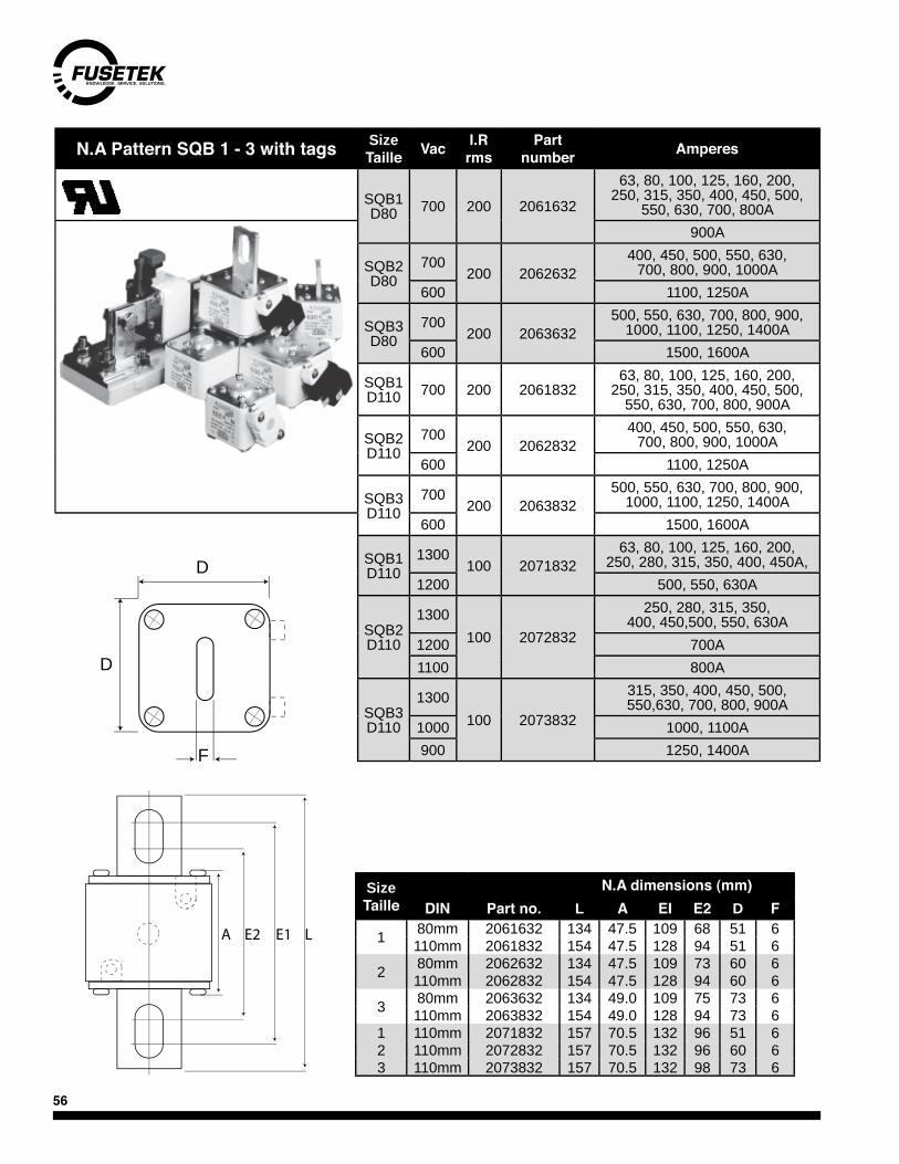
N.A Pattern SQB 1 - 3 with tags Size Taille Vac I.R
rmsPart
number Amperes
SQB1 D80 700 200 2061632
63, 80, 100, 125, 160, 200, 250, 315, 350, 400, 450, 500,
550, 630, 700, 800A900A
SQB2 D80
700200 2062632
400, 450, 500, 550, 630, 700, 800, 900, 1000A
600 1100, 1250A
SQB3 D80
700200 2063632
500, 550, 630, 700, 800, 900, 1000, 1100, 1250, 1400A
600 1500, 1600A
SQB1 D110 700 200 2061832
63, 80, 100, 125, 160, 200, 250, 315, 350, 400, 450, 500,
550, 630, 700, 800, 900A
SQB2 D110
700200 2062832
400, 450, 500, 550, 630, 700, 800, 900, 1000A
600 1100, 1250A
SQB3 D110
700200 2063832
500, 550, 630, 700, 800, 900, 1000, 1100, 1250, 1400A
600 1500, 1600A
SQB1 D110
1300100 2071832
63, 80, 100, 125, 160, 200,250, 280, 315, 350, 400, 450A,
1200 500, 550, 630A
SQB2 D110
1300100 2072832
250, 280, 315, 350, 400, 450,500, 550, 630A
1200 700A1100 800A
SQB3 D110
1300100 2073832
315, 350, 400, 450, 500, 550,630, 700, 800, 900A
1000 1000, 1100A900 1250, 1400A
SizeTaille
N.A dimensions (mm)DIN Part no. L A EI E2 D F
1 80mm 2061632 134 47.5 109 68 51 6110mm 2061832 154 47.5 128 94 51 6
2 80mm 2062632 134 47.5 109 73 60 6110mm 2062832 154 47.5 128 94 60 6
3 80mm 2063632 134 49.0 109 75 73 6110mm 2063832 154 49.0 128 94 73 6
1 110mm 2071832 157 70.5 132 96 51 62 110mm 2072832 157 70.5 132 96 60 63 110mm 2073832 157 70.5 132 98 73 6
E2 E1 LA
D
D
F

57
EURO Pattern SQB 1 - 3 with tags
Size Taille Vac I.R
rmsPart
number Amperes
SQB1 D80 700 200 2061232
63, 80, 100, 125, 160, 200, 250, 315, 350, 400, 450, 500, 550,
630, 700, 800, 900A
SQB2 D80
700200 2062232
400, 450, 500, 550, 630, 700, 800, 900, 1000A
600 1100, 1250A
SQB3 D80
700200 2063232
500, 550, 630, 700, 800, 900, 1000, 1100, 1250, 1400A,
600 1500, 1600A
SQB1 D110
700 200 206153263, 80, 100, 125, 160, 200, 250, 315, 350, 400, 450, 500, 550,
630, 700, 800A600 200 2061532 900A
SQB2 D110
700 200 2062532 400, 450, 500, 550, 630, 700, 800, 900, 1000A
600 200 2062532 1100, 1250A
SQB3 D110
700 200 2063532 500, 550, 630, 700, 800, 900, 1000, 1100, 1250, 1400A
600 200 2063532 1500, 1600A
SQB1 D110
1300
100
207153250, 63, 80, 100, 125, 160, 200,250, 280, 315, 350, 400, 450A
1200 500, 550, 630
SQB2 D110
13002072532
250, 280, 315, 350, 400, 450, 500, 550, 630A
1200 700A, (800A @1100V)
SQB3 D110
13002073532
315, 350, 400, 450, 500, 550,630, 700, 800, 900A
1000 1000,1100A900 1000, 1250, 1400A
SizeTailleSQB
Dimensions (mm)
DIN Part no. L A E D F
SQB1 80mm 2061232 110 47.5 76 51 6110mm 2061532 134 47.5 106 51 6
SQB2 80mm 2062232 110 47.5 76 60 6110mm 2062532 134 47.5 106 60 6
SQB3 80mm 2063232 110 49 76 73 6110mm 2063532 134 49 106 73 6
SQB1 110mm 2071532 138 70.5 106 73 6SQB2 110mm 2072532 138 70.5 106 73 6SQB3 110mm 2073532 138 70.5 106 73 6
LEA
11
25
11
D
D
F
14
40

58
N.A & Euro SQB 1-3 UR Size Taille Vac I.R
rmsPart
number AmperesNorth American Pattern - UNC threads
SQB1 700 200 2066432 63, 80, 100, 125, 160, 200A
250, 315, 350, 400, 450, 500A550, 630, 700, 800A
900A
SQB2 700 200 2067432400, 450, 500, 550, 630,
700, 800, 900, 1000A600 1100, 1250A
SQB3 700 200 2068432 500, 550, 630, 700, 800, 900A
1000,1100, 1250, 1400A600 1500, 1600A
SQB1 1300 100 2076432 50, 63, 80, 100, 125, 160, 200A
250, 315, 350, 400, 450A1200 500, 550, 630A
SQB2 1300
100 2077432 250, 280, 315, 350, 400,
550, 500, 550, 630A1200 700A1100 800A
SQB3 1300
1002078432
315, 350, 400, 450, 500, 550, 630, 700, 800, 900A
1000 1000, 1100A900 100 1250, 1400A
European Pattern - Metric threads
SQB1 700 200 2066132 63, 80, 100, 125, 160, 200A
250, 315, 350, 400, 450, 500A550, 630, 700, 800A
900A
SQB2 700 200 2067132 400, 450, 500, 550, 630,
700, 800, 900, 1000A600 1100, 1250,
SQB3 700 200 2068132 500, 550, 630, 700, 800, 900A
1000,1100, 1250, 1400A600 1500, 1600A
SQB1 1300 100 2076132 50, 63, 80, 100, 125, 160, 200A250, 280, 315, 350, 400, 450A
1200 500, 550, 630A
SQB2 1300
100 2077132 250, 280, 315, 350, 400, 450A
500, 550, 630A1200 700A1100 800A
SQB3 1300
100 2078132 315, 350, 400, 450, 500, 550, 630A
700, 800, 900A1000 1000, 1100A900 1250, 1400A
SizeTailleSQB
Vac Part no.
Dimensions (mm)
D L Thread
1
700
2066432 51 50.5 5/16-18unc2066132 51 50.5 M8
2 2067432 60 50.5 3/8-16 unc2067132 60 50.5 M10
3 2068432 73 50.5 1/2-13unc2068132 73 50.5 M12)
1
1300
2076432 51 73.5 5/16-18unc2076132 51 73.5 M8
2 2077432 60 73.5 3/8-16unc2077132 60 73.5 M10
3 2078432 73 73.5 1/2-13unc2078132 73 73.5 M12
L
D
D

59
Electrical Characteristics 600-690/700V SQB 1 - 3 Operating class "aR"Body Size Amp
ratingIEC voltage
(Vac)UL voltage
(Vac)Power Loss
(W)Pre-arcing
12t (A2s)Total I2t
600V A2s
SQB1
63 690 700 19 160 85080 690 700 24 260 1400100 690 700 30 420 2300125 690 700 35 600 3100160 690 700 40 1400 7500200 690 700 44 2400 13000250 690 700 51 3700 21000315 690 700 59 6600 39000350 690 700 61 9900 55000400 690 700 65 17000 96000450 690 700 70 22000 130000500 690 700 72 31000 180000550 690 700 75 41000 250000630 690 700 80 61000 370000700 690 700 85 86000 490000800 690 700 99 120000 750000900 690 700 105 170000 990000
* TESTED AT 1.05 X UN
Amp rating
IEC voltage (Vac)
UL voltage (Vac)
Power Loss (W)
Pre-arcing 12t (A2s)
Total I2t 600V A2s
SQB2
400 690 700 65 13000 75000450 690 700 75 18000 110000500 690 700 80 26000 150000550 690 700 85 36000 195000630 690 700 94 55000 300000700 690 700 99 74000 410000800 690 700 108 100000 580000900 690 700 111 170000 9500001000 690 700 115 230000 12600001100 600 600 130 290000 16000001250 600 600 140 370000 2140000
* TESTED AT 1.05 X UN
Amp rating
IEC voltage (Vac)
UL voltage (Vac)
Power Loss (W)
Pre-arcing 12t (A2s)
Total I2t 600V A2s
SQB3
500 690 700 90 18000 100000550 690 700 100 22000 130000630 690 700 108 31000 190000700 690 700 113 50000 300000800 690 700 118 85000 480000900 690 700 120 115000 6600001000 690 700 131 140000 8600001100 690 700 136 210000 12000001250 690 700 147 290000 17500001400 690 700 161 380000 22000001500 600 600 170 490000 30000001600 600 600 190 590000 3700000
TESTED AT 1.05 X UN
***
****
*****
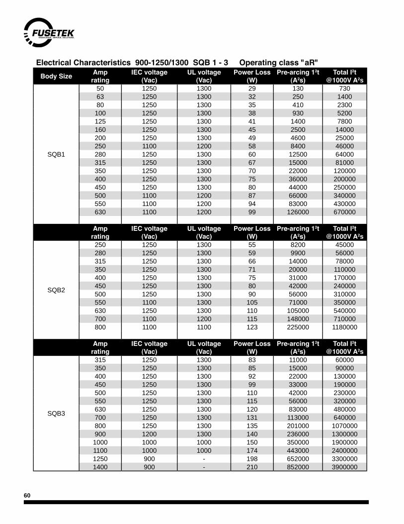
60
Electrical Characteristics 900-1250/1300 SQB 1 - 3 Operating class "aR" Body Size Amp
ratingIEC voltage
(Vac)UL voltage
(Vac)Power Loss
(W)Pre-arcing 12t
(A2s)Total I2t
@1000V A2s
SQB1
50 1250 1300 29 130 73063 1250 1300 32 250 140080 1250 1300 35 410 2300
100 1250 1300 38 930 5200125 1250 1300 41 1400 7800160 1250 1300 45 2500 14000200 1250 1300 49 4600 25000250 1100 1200 58 8400 46000280 1250 1300 60 12500 64000315 1250 1300 67 15000 81000350 1250 1300 70 22000 120000400 1250 1300 75 36000 200000450 1250 1300 80 44000 250000500 1100 1200 87 66000 340000550 1100 1200 94 83000 430000630 1100 1200 99 126000 670000
Amp rating
IEC voltage (Vac)
UL voltage (Vac)
Power Loss (W)
Pre-arcing 12t (A2s)
Total I2t @1000V A2s
SQB2
250 1250 1300 55 8200 45000280 1250 1300 59 9900 56000315 1250 1300 66 14000 78000350 1250 1300 71 20000 110000400 1250 1300 75 31000 170000450 1250 1300 80 42000 240000500 1250 1300 90 56000 310000550 1100 1300 105 71000 350000630 1250 1300 110 105000 540000700 1100 1200 115 148000 710000800 1100 1100 123 225000 1180000
Amp rating
IEC voltage (Vac)
UL voltage (Vac)
Power Loss (W)
Pre-arcing 12t (A2s)
Total I2t @1000V A2s
SQB3
315 1250 1300 83 11000 60000350 1250 1300 85 15000 90000400 1250 1300 92 22000 130000450 1250 1300 99 33000 190000500 1250 1300 110 42000 230000550 1250 1300 115 56000 320000630 1250 1300 120 83000 480000700 1250 1300 131 113000 640000800 1250 1300 135 201000 1070000900 1200 1300 140 236000 13000001000 1000 1000 150 350000 19000001100 1000 1000 174 443000 24000001250 900 - 198 652000 33000001400 900 - 210 852000 3900000

61
Time Current Curves for 600-690/700VSQB 1-3
Time Current CharacteristicsTime Current Characteristics
SQB2
SQB3
SBQ1
Time Current Characteristics
SQB1

62
Time Current Curves for 900-1250/1300VSQB 1-3
Time Current Characteristics
SQB2
Time Current Characteristics
SQB3
Time Current Characteristics
SQB1

63
SIZE 000 & 00 - D80 Size Taille
I.R kA rms Vac Part
number Amperes
000
200 690 *2055834 16, 20, 25, 32 ,40, 50, 63, 80A200 700 *2055820 100, 125,160, 200, 250, 315A
200 700 2028220 32, 35, 40, 50, 63, 80, 100, 125, 160, 200, 250, 315A
00
200 700 2018920 32, 35, 40, 50, 63, 80, 100, 125, 160, 200, 250, 315, 350, 400A
200 700 *2041204 16, 20, 25A
200 700 *2041220 32, 35, 40, 50, 63, 80, 100, 125A160, 200, 250, 315, 350, 400A
00 200 1000 *2056220 32, 35, 40, 50, 63, 80, 100, 125, 160, 200, 250, 315A
* With bracket for micro switch
Dimensions (mm)00 000
A 105 100B 29.5 20.4C 47 38
CC 80 80D 10.3 8.5E 28.8 20
Electrical Characteristics 690/700V Operating class "gRL"
BC
CC
E
D
B
A
Accessories/Accessories for/pour
Adaptor for SQB80mm fuses 2800102
Adapter for SQB110mm fuses 2800103
GL-Microswitch 250V / 10A 2800104
GL-Microswitch for NH00 DIN 80 SBQ 1-3 250V / 5A one change over
contact
2800201
GL-Microswitch for NH00 DIN 80 NH000-4 250V / 5A one change over
contact
2800202
microswitch
adapter
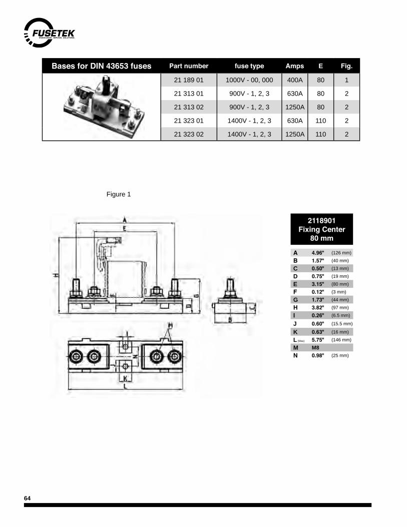
64
Bases for DIN 43653 fuses Part number fuse type Amps E Fig.
21 189 01 1000V - 00, 000 400A 80 1
21 313 01 900V - 1, 2, 3 630A 80 2
21 313 02 900V - 1, 2, 3 1250A 80 2
21 323 01 1400V - 1, 2, 3 630A 110 2
21 323 02 1400V - 1, 2, 3 1250A 110 2
2118901Fixing Center
80 mm
A 4.96" (126 mm)B 1.57" (40 mm)C 0.50" (13 mm)D 0.75" (19 mm)E 3.15" (80 mm)F 0.12" (3 mm)G 1.73" (44 mm)H 3.82" (97 mm)I 0.26" (6.5 mm)
J 0.60" (15.5 mm)
K 0.63" (16 mm)L (Max) 5.75" (146 mm)M M8N 0.98" (25 mm)
Figure 1

65
SQB 1-3 Bases
630A 1250A2131301 2132301
Fixing Center80 mm
Fixing Center110 mm
A 5.90" (150 mm) A 7.10" (180 mm)B 3.35" (85 mm) B 3.35" (85 mm)C 0.63" (16 mm) C 0.63" (16 mm)D 0.83" (21 mm) D 0.83" (21 mm)E 3.15" (90 mm) E 4.33" (110 mm)F 0.30" (8 mm) F 0.30" (8 mm)G 1.80" (46 mm) G 1.80" (46 mm)H (Size 1) 5.00" (127 mm) H (Size 1) 5.00" (127 mm)H (Size 2) 5.12" (130 mm) H (Size 2) 5.12" (130 mm)H (Size 3) 5.40" (137 mm) H (Size 3) 5.40" (137 mm)I 0.35" (9 mm) I 0.35" (9 mm)
J (Size 1) 4.10" (104 mm) J (Size 1) 4.10" (104 mm)
J (Size 2) 4.25" (108 mm) J (Size 2) 4.25" (108 mm)J (Size 3) 4.53" (115 mm) J (Size 3) 4.53" (115 mm)K 0.98" (25 mm) K 0.98" (25 mm)L (Max) 8.07" (205 mm) L (Max) 8.07" (205 mm)M M10 M M10N 2.36" (60 mm) N 2.36" (60 mm)O 1.57" (40 mm) O 1.57" (40 mm)
2131302 2132302Fixing Center
80 mmFixing Center
110 mm
A 5.90" (150 mm) A 7.10" (180 mm)B 3.35" (85 mm) B 3.35" (85 mm)C 0.63" (16 mm) C 0.63" (16 mm)D 0.83" (21 mm) D 0.83" (21 mm)E 3.15" (90 mm) E 4.33" (110 mm)F 0.30" (8 mm) F 0.30" (8 mm)G 1.80" (46 mm) G 1.80" (46 mm)H (Size 1) 5.00" (127 mm) H (Size 1) 5.00" (127 mm)H (Size 2) 5.12" (130 mm) H (Size 2) 5.12" (130 mm)H (Size 3) 5.40" (137 mm) H (Size 3) 5.40" (137 mm)I 0.35" (9 mm) I 0.35" (9 mm)
J (Size 1) 4.10" (104 mm) J (Size 1) 4.10" (104 mm)
J (Size 2) 4.25" (108 mm) J (Size 2) 4.25" (108 mm)J (Size 3) 4.53" (115 mm) J (Size 3) 4.53" (115 mm)K 0.98" (25 mm) K 0.98" (25 mm)L (Max) 8.07" (205 mm) L (Max) 8.07" (205 mm)M M10 M M10N 2.36" (60 mm) N 2.36" (60 mm)O 1.57" (40 mm) O 1.57" (40 mm)
Figure 2

66
Ferrule fusesUsually found in imported equipment. Available in the following characteristics;
F = Fast - overload and short circuit. M = medium - overload and short circuit. FF = Ultrafast - short circuit only.gL = General purpose-overload and short circuit.aM = Motor circuit - short circuit only.gR = Ultrafast-overload and short circuit.
Metric Diam x Length (mm) Vac Speed Part
number Ratings available
Ferrule and Electronic fuses - General Specifications5 x 20 250 FF 7000140 100ma - 12.5A5 x 20 380 FF 7000740 100mA - 4A5 x 25 250 M 172525 32mA - 10A
5 x 25 w. ind. 250 M 172526 50mA - 10A5 x 25 w/ind. 450 F 7008913 250mA - 10A
5 x 30 500 M 172530 32mA - 10A6 x 32 700 FF 7012540 100mA - 20A (2.5-20A - 500V)6 x 32 600 F 7009463 160mA - 25A (20&25A - 440V)6 x 32 500 T 189140 100mA - 32A (20&25A - 440V, 32A - 250V)6 x 32 1000 FF 7017240 315, 500mA, 1, 1.6, 2A8 x 32 380 gL 5006608 2 - 20A
10 x 38 700 gR 5017906 1 - 30A10 x 38 1000 gR 5019906 4, 6, 8, 10, 12, 16A10x51 60 7001908 500mA - 6.3A14x 51 660 gL 5005808 1 - 25A (32&40A - 500V only)14x 51 660 aM 5005807 1/4 - 40A (32&40A - 500V only)
14 x 51 w. ind. 690 gL 5005908 2 - 40A (32-40A - 500V)14x 51 700 gR 5012406 2, 4, 6, 8, 10, 12, 16, 20, 25, 32, 40, 50A
14 x 51 ind. 700 gR 5012606 2, 4, 6, 8, 10, 12, 16, 20, 25, 32, 40, 50A22 x 58 660 gL 5006008 (1-30A - use Class J) 40, 50, 63, 80, 100A
22 x 58 w. ind. 660 gL 5006108 2 - 100A (63 to 100A - 500V)22 x 58 660 aM 5006007 (1-30A - use Class J) 40, 50, 63, 80, 100A
22 x 58 w. ind. 660 aM 5006107 2 - 100A (63 to 100A - 500V)22 x 58 700 gR 5014006 12, 16, 20, 25, 32, 40, 50, 63, 80, 100A
22 x 58 ind. 700 gR 5014206 12, 16, 20, 25, 32, 40, 50, 63, 80, 100A
L
D
ind = indicator
Standard ratings available: mA 32, 40, 50, 63, 80, 100, 125, 160, 200, 250, 315, 400, 500, 630, 800mA, 1, 1.25, 1.6, 2, 2.5, 3.15, 4, 5, 6.3, 8, 10, 12, 16, 20, 25, 32, 40, 50, 63, 80, 100A
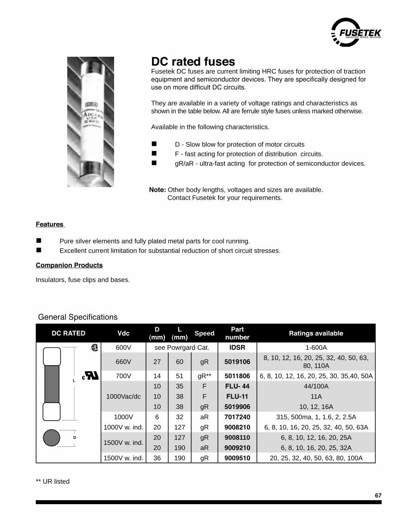
67
DC RATED Vdc D (mm)
L (mm) Speed Part
number Ratings available
600V see Powrgard Cat. IDSR 1-600A
660V 27 60 gR 5019106 8, 10, 12, 16, 20, 25, 32, 40, 50, 63, 80, 110A
700V 14 51 gR** 5011806 6, 8, 10, 12, 16, 20, 25, 30, 35,40, 50A
1000Vac/dc10 35 F FLU- 44 44/100A10 38 F FLU-11 11A10 38 gR 5019906 10, 12, 16A
1000V 6 32 aR 7017240 315, 500ma, 1, 1.6, 2, 2.5A1000V w. ind. 20 127 gR 9008210 6, 8, 10, 16, 20, 25, 32, 40, 50, 63A
1500V w. ind.20 127 gR 9008110 6, 8, 10, 12, 16, 20, 25A20 190 aR 9009210 6, 8, 10, 16, 20, 25, 32A
1500V w. ind. 36 190 gR 9009510 20, 25, 32, 40, 50, 63, 80, 100A
DC rated fusesFusetek DC fuses are current limiting HRC fuses for protection of traction equipment and semiconductor devices. They are specifically designed for use on more difficult DC circuits.
They are available in a variety of voltage ratings and characteristics as shown in the table below. All are ferrule style fuses unless marked otherwise.
Available in the following characteristics.
n D - Slow blow for protection of motor circuitsn F - fast acting for protection of distribution circuits.n gR/aR - ultra-fast acting for protection of semiconductor devices.
Features
n Pure silver elements and fully plated metal parts for cool running.n Excellent current limitation for substantial reduction of short circuit stresses.
Companion Products
Insulators, fuse clips and bases.
L
D
General Specifications
** UR listed
Note: Other body lengths, voltages and sizes are available. Contact Fusetek for your requirements.

68
EPJ Pedestal fusesSpecifications
Voltage Rating: 440VacInterrupting Rating: 200kA rms Amp Range: 100-200ARatings available: 100, 125, 150, 200A
part number example EPJ-125
These fuses are typically used in lighting pedestal distribution enclosures. Edmonton Power drawing E-80-A
They will fit Burndy SPB-1 terminal blocks or equal.
EPD Distribution fusesSpecifications
Voltage Rating: 600Vac
Interrupting Rating: 200kA rms Ratings available: 125, 150, 200A
part number example EPD-200
These fuses are typically used in residential distribution applications as a bus mounted splitter fuse.
Edmonton Power drawing: 2E-74-A
dimensions (mm)
25
42
80105
5
78
110
138
405
25
dimensions (mm)

69
Solar Products
Specifications
Voltage Rating: 1000 VDCAmperage Ratings: 2, 3, 4, 5, 6, 8, 10, 12, 15, 20, 25, 30Max. Interrupt Rating: 20,000 amperes; L/R < 2mSMin. Interrupt Rating: 1-12 amperes, 2 X Irating 15-30 amperes, 1.35 X IratingApproval: CSA & UL Rec. File No. E10480
SPF Series 1000VDC Solar FuseThe SPF Solar Protection Fuse series has been specifically designed for photovoltaic (PV) systems. This family of midget fuses (10x38mm) can safely protect PV modules and their conductors from reverse overcur-rent conditions despite the associated challenges of DC power.
Product Features• UL Recognized 1000VDC maximum• 13 ampere ratings for flexible design• 20,000 kA interrupting rating• High performance in compact midget size• RoHS compliant and lead free• Touch safe DIN rail holder available• PCB leaded version available
LPHV Touch-Safe Fuse HolderSome applications include combiner boxes and inverters in utility-scale photovoltaic systems. LPHV is ideal for isolating photovoltaic module strings during maintenance, but is not designed for load break.
SpecificationsVoltage Rating: 1000 VDCAmperage Rating: 30 amperes Approval: Self-certified with SPF & FLU fusesWire Range: #6 - #14 CU 75 ̊CTerminal Type: Pressure Plate Terminal Torque: 17.7 in-lbs Fuse Type: SPF & FLU midget (10X38mm)Material: Thermo-PlasticFlammability Rating: UL - 94VO SCCR Rating: 20,000 amperesPart Numbers: LPHV001 (1 pole) LPHV002 (2 pole) LPHV003 (3 pole) LPHV004 (4 pole)Multi-pole Assembly Kit: CHYP001 Kit allows up to 10 holders to be connected
Product Features• 1000VDC rating when used with Littelfuse SPF or FLU midget fuse series• 30 amperes rated • Mountable on 35mm Din Rail • Safe and easy installation and removal of fuses. No special fuse pullers or tools required. • Compact design • RoHS compliant and Pb free

70
The SPFR series was designed to meet the growing needs of the solar industry with higher amperage and voltage requirements.
SpecificationsVoltage Rating: 1000 VdcAmpere Rating: 250, 300, 350 and 400 AInterrupting Rating: 10,000 A at 1ms Time ConstantFuse Type: Fast-acting Approvals: CSA & UL Recognized 1000 Vdc UL 248
Ordering InformationCatalog number – SPFR250 System number – SPFR250.X
Applications• Solar Inverters • High amperage combiner boxes
Features/Benefits• DC Voltage rating meets European system requirements and North American utility scale requirements• Multiple amperage ratings • RoHS compliant • Class H Dimensions • Full Range Protection
Wohner 1000VDC Midget fuseholders are compact DIN rail mountable fuseholders intended for use in the solar industry with matching 1000VDC midget fuses.
Technical SpecificationsFuse Types: Class CC & MidgetVoltage Rating: 1000VDC - Solar - Midget onlyAmpere Rating: 30A.Terminal Style: Box ConnectorWire size: 1 wire #18-#4 AWG or 2 wires #18-#6 AWG (must be stranded and same size)Tightening Torque: 18-22 lb/in (2.0 -2.5Nm)Flammability rating: UL94Approvals: Pending
Features and Benefits
Accepts all standard Midget fuses• Larger wire capacity• Non-Indicating and Indicating versions available• Easy installation and removal of fuses• Mounts on standard 35mm DIN rail• Smooth Cam action• Ventilated for cooler operation • Insensitive to DC polarity• Ganging kits available to assemble 2 and 3P• Wide range of accessories•
WOHNER 1000VDC Midget Fuse holder
LITTELFUSE 1000VDC Solar Fuse
Ordering InformationPart No. Non-Indicating - 31971.000Part No. Indicating - 31973.000
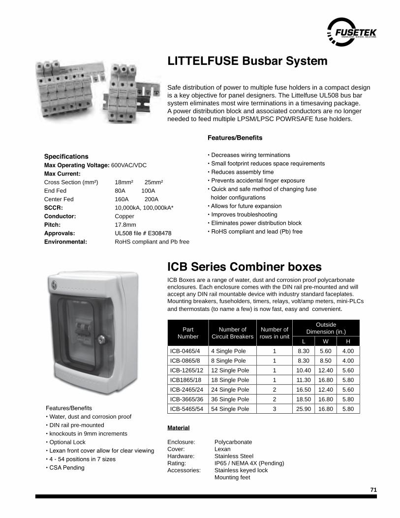
71
Safe distribution of power to multiple fuse holders in a compact design is a key objective for panel designers. The Littelfuse UL508 bus bar system eliminates most wire terminations in a timesaving package. A power distribution block and associated conductors are no longer needed to feed multiple LPSM/LPSC POWRSAFE fuse holders.
SpecificationsMax Operating Voltage: 600VAC/VDCMax Current:Cross Section (mm²) 18mm² 25mm²End Fed 80A 100ACenter Fed 160A 200ASCCR: 10,000kA, 100,000kA*Conductor: CopperPitch: 17.8mmApprovals: UL508 file # E308478Environmental: RoHS compliant and Pb free
LITTELFUSE Busbar System
Features/Benefits
• Decreases wiring terminations• Small footprint reduces space requirements• Reduces assembly time• Prevents accidental finger exposure• Quick and safe method of changing fuse holder configurations• Allows for future expansion• Improves troubleshooting• Eliminates power distribution block• RoHS compliant and lead (Pb) free
ICB Series Combiner boxes
Material
Enclosure: PolycarbonateCover: LexanHardware: Stainless SteelRating: IP65 / NEMA 4X (Pending)Accessories: Stainless keyed lock Mounting feet
ICB Boxes are a range of water, dust and corrosion proof polycarbonate enclosures. Each enclosure comes with the DIN rail pre-mounted and will accept any DIN rail mountable device with industry standard faceplates. Mounting breakers, fuseholders, timers, relays, volt/amp meters, mini-PLCs and thermostats (to name a few) is now fast, easy and convenient.
Part Number
Number ofCircuit Breakers
Number of rows in unit
OutsideDimension (in.)
L W HICB-0465/4 4 Single Pole 1 8.30 5.60 4.00ICB-0865/8 8 Single Pole 1 8.30 8.50 4.00ICB-1265/12 12 Single Pole 1 10.40 12.40 5.60ICB1865/18 18 Single Pole 1 11.30 16.80 5.80ICB-2465/24 24 Single Pole 2 16.50 12.40 5.60ICB-3665/36 36 Single Pole 2 18.50 16.80 5.80ICB-5465/54 54 Single Pole 3 25.90 16.80 5.80Features/Benefits
• Water, dust and corrosion proof• DIN rail pre-mounted• knockouts in 9mm increments• Optional Lock• Lexan front cover allow for clear viewing• 4 - 54 positions in 7 sizes• CSA Pending
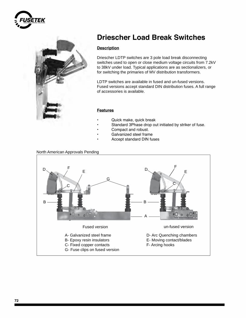
72
Driescher Load Break SwitchesDescription
Driescher LDTP switches are 3 pole load break disconnecting switches used to open or close medium voltage circuits from 7.2kV to 38kV under load. Typical applications are as sectionalizers, or for switching the primaries of MV distribution transformers.
LDTP switches are available in fused and un-fused versions. Fused versions accept standard DIN distribution fuses. A full range of accessories is available.
Features
• Quick make, quick break• Standard 3Phase drop out initiated by striker of fuse.• Compact and robust.• Galvanized steel frame• Accept standard DIN fuses
D- Arc Quenching chambersE- Moving contact/bladesF- Arcing hooks
A- Galvanized steel frameB- Epoxy resin insulatorsC- Fixed copper contactsG- Fuse clips on fused version
Fused version un-fused version
North American Approvals Pending
FD
B
FE
CG
A
B
D E
C

73
General specifications
Amp rating 400A, 630A and 1200AVoltage rating 7.2kV (BIL-60kv) 17.5kV (BIL-95kV) 25.8kV (BIL-125kV) 38kV (BIL-150kV)
Asymmetrical peak current 65kA3s. withstand 25kAOptions available Shunt trip, auxiliary contacts, integral ground switch, motor driven operator, dual fuse clips (fused version only)
Dimensions
Dimensions shown are for general overall reference. For detailed dimensions technical data, please contact Fusetek.
Dimensional drawing and table of dimensions
LDPT Dimensions (mm) kV Fused Version kV Un-Fused Version
E M A R T M A R T7.2kV 292 570 943 745 960 7.2kV 570 940 455 5257.2kV 442 570 943 895 1110 7.2kV 570 940 455 52517.5kV 442 635 943 895 1110 17.5kV 635 940 455 52525.8kV 442 730 1093 965 1160 25.8kV 730 1093 485 57538kV 537 910 1093 1180 1355 38kV 910 1093 500 675

74
IndexPart Page Part Page Part Page
..E-1C15.5 24-28
..E-1C15.5 24-28
..E-1C2.75 24-28
..E-1C25.8 24-28
..E-1C38 24-28
..E-1C5.5 24-28
..E-1C5.5 24-28
..E-1C8.25 24-28
..E-1C8.3 24-28
..E-1CL15.5 24-28
..E-1CL5.5 24-28
..E-2C15.5 24-28
..E-2C15.5 24-28
..E-2C2.75 24-28
..E-2C25.8 24-28
..E-2C38 24-28
..E-2C5.5 24-28
..E-2C5.5 24-28
..E-2C8.3 24-28
..E-2C8.3 24-28
..E-3C15.5 24-28
..E-3C8.3 24-280038 530039 530040 530041 530042 531000204.. 531001101.. 531002704.. 531002804.. 531002904.. 5315GSE-.. 24-2815GSE2-.. 24-2815NLE-.. 24-2815NLE-.. 24-28172525-.. 66172526-.. 66172530-.. 66184000.. 30-31185000.. 30-31186000.. 30-31187000.. 30-31189140-.. 662018920-.. 632021013-.. 542021113-.. 542021120-.. 542021213-.. 542021220-.. 542021313-.. 542021320-.. 542028220-.. 632038404-.. 54
2041204-.. 632041220-.. 632045213-.. 542047734-.. 542055820-.. 632055834-.. 632055920-.. 522056220-.. 632061232-.. 572061532-.. 572061632-.. 562061832-.. 562062232-.. 572062532-.. 572062632-.. 562062832-.. 562063232-.. 572063532-.. 572063632-.. 562063832-.. 562066132-.. 582066432-.. 582067132-.. 582067432-.. 582068132-.. 582068432-.. 582071532-.. 572071832-.. 562072532-.. 572072832-.. 562073532-.. 572073832-.. 562076132-.. 572076432-.. 582077132-.. 582077432-.. 582078132-.. 582078432-.. 582100101 542100103 542100204 542100301 542100303 542100401 542100403 542100501 542118901 642131301 642131302 642132301 642132302 642138401 542800102 632800103 63
2800104 632800201 632800202 633000413-.. 353000813-.. 383001213-.. 353001613-.. 383002013-.. 353002014-.. 353002413-.. 383009813-.. 343009913-.. 343010013-.. 343010014-.. 343011014-.. 343021114-.. 353023113-.. 363023213-.. 363023313-.. 363023314-.. 363028713-.. 373028813-.. 373028913-.. 373033713-.. 393033813-.. 393033913-.. 393034921.. 423035021.. 423035121.. 423035221.. 423035321.. 423100102 403100110 483100110 473100302 403100502 403100702 403100302.20 4931548 6931549 6931971.000 6831973.000 683400101.20 494.8NPT-.. 30-315005306-.. 515005406-.. 515005807-.. 665005808-.. 665005908-.. 665006007-.. 665006008-.. 665006107-.. 665006108-.. 665006608-.. 66