class 8903 ·1981 . com . elec · pdf file · 2011-09-12class 8903...
TRANSCRIPT

Class 8903 JAMUAFt'l, ·1981
Lighting Contactors CONTENTS
Description Class Pages
Introduction . . . . . . . . . . . . . . . . . . . . . . 8903 . . . . . . . . 2 Ratings . . . . . . . . . . . . . . . . . . . . . . . . . 8903 . . . . . . . . 3 Types L & S Electrically Held
Lighting Contactors . . . . . . . . . . . . . 8903 . . . . . . . . 4 Types LL & S Met::hanically Held
Lighting Contactors . . . . . . . . . . . . . 8903 . . . . . . . . 5 Type S Combination
Lighting Contactors . . . . . . . . . . . . . 8903 . . . . . . . . 6 NIGHT-MASTER Outdoor
Lighting Controllers . . . . . . . . . . . . . 8903. . . . . . . . 7 Application Data . . . . . . . . . . . . . . . . . . 8903 ..... 8-10 Dimensions . . . . . . . . . . . . . . . . . . . . . . 8903 . . . . 1 1 -15
II•ISQUARE D COMPANY 1 www .
Elec
tricalP
artM
anua
ls . c
om
www . El
ectric
alPar
tMan
uals
. com

II LIGHTING CONTACTORS JANUARY, 1981
APPLICATION OF LIGHTING CONTACTORS
Lighting contactors have evolved from the need for more than just simple on-off manual control of lights. Today's requirements call for the development of new and varied types of control . Often , the application will call for remote control of lighting from some distant location. This control may or may not be in addition to a master control station at a central location. Or certain applications include the use of automatic control by time clocks or photoelectric cells . Whatever the need may be, applications are increasing , and lighting contactors are designed to meet the ever-changing requirements.
Square D lighting contactors offer a time proven design for better electrical and mechanical performance. They are used wherever reliable, convenient and economical control of indoor and outdoor lighting is required. Typical installations include:
o parking lots o shopping centers o industrial plants o stadiums o office buildings o airports o theaters and auditoriums o hospitals and institutions
LIGH TING CONTACTORS FOR ENERGY M ANAGEMENT
Lighting contactors should be an integral part of any Energy Management System. They help conserve energy consumption and reduce utility bills by providing three types of control.
Lighting contactors offer both centralized and remote control of lighting. Circuits can be turned on and off from a number of remote locations in addition to a master control station.
They also offer selective switching of l ights. Selective switchi ng is the control of one or more individual lighting circuits, independent of the other circuits. This design allows the potential for turning on only the amount of l ighting that is actually needed .
L ighting contactors can provide automatic control to insure that lights will be turned off when not needed . There are a number of devices that, when used with lighting contactors, offer a convenient and reliable method of automatically controlling lighting loads: program time clock, photoelectric cell, programmable controller and demand controller.
ELECTRICALLY HELD VS. MECHANICALLY HELD
ELECTRICALLY HELD Electrically held lighting contactors require voltage to be continuously applied to the coil to maintain the contacts in the closed position (or open position in the case of normally closed contacts). Electrically held devices are used:
o wherever a high rate of operation is encountered (such as heating elements or electric furnaces).
0 in areas where the ac hum of a continuously energized coil would not be annoying, such as factories , machine shops or outdoors.
o with three-wire control schemes to provide low voltage protec tion, thus preventing the load from being automatically energized after restoration of power following a failure.
OFF
2 WIRE PILOT
DEVICE I -----1 f------------------_J
TO COMMON OR SEPARATE CONTROL SUPPLY
Electrically Held
MECHANICALLY HELD
Mechanically held lighting contactors require only momentary application of voltage to be latched (turned on) or unlatched (turned off) . Since the contacts are mechanically held closed (open if normally closed contacts) , the latch and unlatch coils need only be momentarily energized , thus eliminating ac hum . This feature allows for quiet application of the mechanically held lighting contactor and makes it the perfect choice for quiet l ocations . As standard , Square D lighting contactors are provided with coil clearing contacts , assuring that the coils will be de-energized even if the control device is held closed. Mechanically held lighting contactors are used wherever:
o quiet operation is required (offices , hospitals, schools).
o circuits are required to remain closed (or open in the case of normally closed contacts) during a power failure.
o excessive control line distances are required .
r=: _ _ j �. roj'�J WL
CLEARING CONTACTS
2 POLE
) PILOT j DEVICE
TO COMMON OR SEPARATE CONTROL SUPPLY
Mechanically Held
INSTALLATION OF LIGHTING CONTACTORS
For new installations , lighting contactors can either be installed right in the lighting panelboard , or in their own enclosure next to or remote from the panelboard .
In existing applications where the l ighting control system is being updated, lighting contactors can be installed in their own enclosure next to a lighting panelboard .
�:-'--------------------------------------------------------------------------- � D CDMPRNY IIJ I © Square D Company 1981 www .
Elec
tricalP
artM
anua
ls . c
om
www . El
ectric
alPar
tMan
uals
. com

JANUARY, 1981
Type of Load
Tungsten
Ballast
Resistance
DC with 2 Poles in Series*
DC with 3 Poles in Series*
Control Circuit (Coil) Voltage
LIGHTING CONTACTORS APPLICATION DATA MAXIMUM VOLTAGE RATINGS
Types L & L L Type SM 20 Amperes 30 Amperes
When Connected When Connected When 2 Poles to Load When 2 Poles to Load
Connected on 1 q, and 3 Poles Connected on 1 <P and 3 Poles 1 Pole to Load to Load on 3</> 1 Pole to Load to Load on 3</>
277AC 480AC 277AC 480AC
277ACi>. 480ACi>. 347AC 600AC
600AC 600AC 600AC 600AC
. .. . 1 25DC . .. . . . . .
. .. . 250DC . .. . 250DC
1 2-600AC Type L, 24-277AC Type LL 24, 32, 1 1 5/125, and 230/250DC 6-600AC
Type L (6 poles max.)
Types SP, SQ, SV & SX 60-300 Amperes
When Connected
1 Pole to Load
277AC
347AC
600AC
. . . .
. . . .
When Connected 2 Poles to Load
on 1</> and 3 Po les to Load on 3</>
480AC
600AC
600AC
250DC
250DC
6-600AC Type SP 24-600AC Types SO & SV
120-600AC Type SX
Ill Types SY, SZ & SJ 400-800 Amperes
When Connected When 2 Poles to Load
Connected on 1 <P and 3 Poles 1 Pole to Load to Load on 3</>
. . . . .. . .
347AC 600AC
600AC 600AC
. .. . . ...
.. .. . ...
1 20-600AC
"'Types L and LL contactors also have a ballast lamp rating of 15 amperes 347VAC when connected 1 Pole to Load and 600VAC when connected 2 Poles to Load on 1¢ and 3 Poles to Load on 3¢.
* For tungsten lamp or resistance loads only. TABLE 1 - KILOWATT RATINGS*
TUNGSTEN LAMP LOADS Tungsten lamps have a positive resistance characteristic (resistance to the flow of electric current increases as its operating temperature increases), thus exhibiting an increase in resistance when the lamp is energized. Therefore, these lamps have a high inrush current of up to 18 times normal current resulting from the low cold resistance of the tungsten. Examples of tungsten lamps include incandescent lamps, iodine lamps, quartz-iodine lamps and infrared lamps.
BALLAST LIGHTING LOADS A ballast lighting load consists of electric discharge (vapor) lamps. All types of vapor lamps possess a negative resistant characteristic . The resistance within the lamp decreases with an increase in current, and vice versa. Without some form of current limiting device in the electric circuit, the current would rise quickly until lamp failure occurred. This current l imiting element is known as the ballast . A ballast is an impedance used to stabilize the current in a vapor lamp. It has the property of increasing in resistance as current through it increases and decreasing in resistance as current decreases. Thus it tends to m aintain a constant current through it. Types of ballast lighting include high intensity discharge (HID) lamps - mercury vapor, metal halide and high pressure sodium -and fluorescent lamps.
RESISTANCE LOADS Square D lighting contactors are fully rated for resistance loads up to 600 volts, Table I. They can be used on resistance-type boilers, electric furnaces, electric water heaters and snow melting cables and panels.
MOTOR LOADS This load consists of motors having an inrush current, or lockedrotor current, of approximately 6 times the full-load current. Square D Type S lighting contactors are fully rated for motor loads and have a horsepower rating equal to the equivalent NEMA-Size motor contactor, Table 2.
MIXED LOADS All Type S lighting contactors are rated to handle mixed loads, consisting of a combination of lighting, resistance and motor loads. Table 3 was developed to make selection of lighting contactors for mixed loads easier. Simply follow these steps: I. Determine the total load by summing the l ighting, resistance and
motor (full load currents of each motor) loads. 2. Calculate the lighting and resistance (total non-motor) load as a
percentage of the total load. 3. From that percent column in Table 3, determine the size lighting
contactor required at the specified motor voltage.
Lighting Contactor Size
Voltage 30 60 100 200 300 400 600 BOO
3 Phase Amp. Amp. Amp. Amp. Amp. Amp. Amp. Amp.
200 v. 10.3 20.7 34.6 69.2 103.9 13B.5 207.8 277.1
230 v. 11.9 23.9 39.B 79.6 119.5 159.3 239.0 31B.7
3BO v. 1 9.7 39.4 65.B 131.6 197.4 263.2 394.9 526.5
460 v. 23.9 47.B 79.6 159.3 239.0 318.6 47B.O 637.4
575 v. 30.0 60.0 99.0 199.0 299.0 39B.4 597.6 796.7
*Resistance heatmg only (three phase system)
TABLE 2- MOTOR LOAD RATINGS
Lighting Contactor Has Same HP Ratings
As Equivalent Size NEMA Size Contactor
30 Ampere NEMA Size 1 60 Ampere NEMA Size 2
1 00 Ampere NEMA Size 3 200 Ampere NEMA Size 4 300 Ampere NEMA Size 5 400 Ampere -600 Ampere NEMA Size 6 800 Ampere NEMA Size 7
TABLE 3- MIXED LOAD RATINGS
Percent Lighting (and/or Resistive) Load Motor Con- 0% 25% 50% 75% Volt-age
tact or Max. Max. Max. Max. Max. Max. Max. Max.
and Ampere Non- Mo- Non- Mo- Non- Mo- Non- Mo-
Phase Rating Motor tor Motor tor Motor tor Motor tor • Amp . HP Amp. HP Amp. HP Amp. H P
30 0 7Yz 7.5 5 15. 3 22.5 1Vz 60 0 10 15. 10 30. 7V2 45. 3
200 V. 100 0 25 25. 20 50. 15 75. 5 200 0 40 50. 40 100. 30 150. 1 5
3 300 0 75 75. 75 150. 50 225. 20
Phase 400 0 125 100. 100 200. 60 300. 30 600 0 150 150. 150 300. 100 450. 50 BOO 0 250 200. 200 400. 125 600. 60
30 0 7Vz 7.5 7Yz 15. 3 22.5 2 60 0 15 1 5. 10 30. 10 45. 3
230 v. 100 0 30 25. 25 50. 15 75. 7Vz 200 0 50 50. 50 100. 30 150. 1 5
3 300 0 100 75. 75 150. 50 225. 25
Phase 400 0 150 100. 100 200. 75 300. 30 600 0 200 1 50. 150 300. 100 450. 50 800 0 300 200. 200 400. 150 600. 75
30 0 10 7.5 7'/z 15. 7Y, 22.5 3 60 0 25 15. 20 30. 15 45. 7Vz
380 v. 100 0 50 25. 40 50. 30 75. 10 200 0 75 50. 75 100. 60 150. 30
3 300 0 150 75. 150 150. 1 00 225. 40
Phase 400 0 250 100. 200 200. 125 300. 60 600 0 300 150. 250 300. 150 450. 75 800 0 450 200. 350 400. 250 600. 125
30 0 10 7.5 7Vz 15. 7Vz 22.5 3 60 0 25 15. 20 30. 20 45. 10
460- 100 0 50 25. 40 50. 30 75. 15 575 v. 200 0 100 50. 100 100. 75 150. 30
3 300 0 200 75. 150 150. 100 225. 50 Phase 400 0 300 100. 200 200. 150 300. 75
600 0 400 150. 350 300. 200 450. 100 BOO 0 600 200. 500 400. 300 600. 150
115 V. 30 0 2 7.5 1'/z 15. '14 22.5 y, S ingle 60 0 3 15. 3 30. 2 45. '14 Phase 100 0 7'h 25. 5 50. 3 75. 2
230 V. 30 0 3 7.5 2 15. 2 22.5 % Single 60 0 7Vz 15. 5 30. 5 45. 2
Phase 100 0 15 25. 15 50. 10 75. 3
�>. Select hghtmg contactor on bas1s of rated motor voltage, whether non-motor load 1s connected line-to-line or line-to-neutral.
IDisquARED���------------------------------------1 www . El
ectric
alPar
tMan
uals
. com
www . El
ectric
alPar
tMan
uals
. com

E LECTRICA L LY HELD LIGHTING CONTACTORS JANuARY, 1981
FOR TUNGSTEN & BALLAST LIGH T ING AND RESISTANCE HEATING LOADS Electrically held lighting contactors are used in areas where the ac hum of a continuously energized coil would not be annoying (factories, outdoors, etc . ) or wherever a high rate of operation is encountered. They are normally operated from a 2 wire, maintained contact input device.
TYPE L TYPE S
• 2-12 Poles • Proven Type S Design • No Arcing Contacts Required • Convertible Contacts with N.O.
and N.C. Indicators • Silver Alloy Double Break Con-
• Enclosed Silver Alloy Double Break Contacts
tacts • Industria I Duty • Adder Pole Kits Available
• Lugs Suitable for Use with Copper or Aluminum Wire (60-800 Amperes Only)
• DC Coils are Available (6 Poles Max.)
• Combination Lighting Contactors Available (pages 6 and 7)
50-60 HERTZ ORDERING INFORMATION- Page 6 MAXIMUM VOLTAGE RATINGS- Page 3
Watertight, Dusttight Flush Mounting and Corrosion- Watertight and Dusttight and
General Purpose General Purpose Resistant Glass- Dusttight Enclosure Driptight I ndustrial Enclosure Enclosure w ith Polyester Enclosure Stainless Steel Use E nclosure
No. Ampere of NEMA Type 1 Plaster Adjustmeot NEMA Type 4X NEMA Type 4 NEMA Type 1 2:j: Open Type Ratings Poles Type Price* Type
2 LG-20 $ 124. LF-20• 3 LG-30 136. LF-30• 4 LG-40 172. LF-40•
20() 6 LG-60 248. LF-60• B LG-BO 324. LF-BQe
1 0 LG-1000 372. LF-1 000•
1 2 LG-1 200 428. LF-1 200•
2 SMG-1 132. SMF-te
30 3 SMG-2 144. SMF-2• 4 SMG-3 176. SMF-3• 5 SMG-4 232. SMF-4•
2 SPG-1 272. SPF-1•
60 3 SPG-2 288. SPF-2• 4 SPG-3 360. SPF-3• 5 SPG-4 520. SPF-4•
2 SQG-1 448. SQF-te
1 00 3 SQG-2 480. SQF-2• 4 SQG-3 592. .. . . 5 SQG-4 848. . . .. 2 SVG-1 1056. SVF-te
200 3 SVG-2 1 1 28. SVF-2• 4 SVG-3 1504. . . . .
300 2 SXG-1 2232. . . . . 3 SXG-2 2400. . . . .
400& 2 SYG-1 5844. . .. . 3 SYG-2 6608. . . . .
600& 2 SZG-1 7174. . . . . 3 SZG-2 8060. . . . .
BOO& 2 SJG-1 8504. .. . . 3 SJG-2 9512. . . . .
* Pnce does not 1nclude holdmg CirCUli mterlock.
$
I
Price*
192. 204. 240.
288. 364. 412.
468.
184. 1 96. 228. 284.
340. 356. 428. 588.
564. 596.
. . ..
. . . . 1136. 1208. . . . .
. . . .
.. . .
. . . . . . . . . . . . . . . .
. . . .
. . . .
Type I Price*
Use 30 Ampere Type S
Consult local Square D
Field Office
SMW-21 e SMW-22• SMW-23e SMW-24•
SPW-21• SPW-22• SPW-23• SPW-24•
SQW-21 SQW-22 . . . . . . . . SVW-21 SVW-22 .. . .
. . . .
. . . .
. . . .
. .. .
. . . .
. . . .
. . . .
. . ..
$ 276. 288. 320. 376.
560. 576. 760. 920.
1 070. 1110.
. . . .
. . .. 2190. 2280. . . . . . . . . ... . . .. . . . . .
. . . . . . .
. . . . . . . .
() Factory conversion of N . O . contacts to any combination of N.C., add $ 1 2 to list price. :j: NEMA Type 1 2 enclosures may be field modified for outdoor applications . For details, see Class 999 1 .
Type Price* Type Price* Type
LW-20• $ 256. LA-20• $ 240. L0-20 LW-30• 268. LA-30• 252. L0-30 LW-40• 304. LA-40• 288. L0-40
LW-60• 352. LA-60• 336. L0-60 LW-Bo• 428. LA-BO• 412. LO-BO LW- 1 000• 476. LA-1000• 460. L0- 1 000
LW-1200e 532. LA-1 200• 516. L0- 1 200
SMW- 1 • 276. SMA-1• 180. SM0-1 SMW-2• 288. SMA-2• 192. SM0-2 SMW-3• 320. SMA-3• 224. SM0-3 SMW-4• 376. SMA-4• 280. SM0-4
SPW- 1 • 560. SPA-te 360. SP0-1 SPW-2• 576. SPA-2• 376. SP0-2 SPW-3• 760. SPA-3• 448. SP0-3 SPW-4• 920. SPA-4• 608. SP0-4
SQW-te 856. SQA-te 552. SQ0-1 SQW-2• 888. SQA-2• 584. SQ0-2 SQW-3 1 1 1 2. SQA-3 696. SQ0-3 SQW-4 1368. SQA-4 952. SQ0-4
SVW-1 1 752. SVA-1 1400. SV0-1 SVW-2 1 824. SVA-2 1472. SV0-2 SVW-3 2488. SVA-3 1968. SV0-3
SXW-1 3112. SXA-1 3112. SX0-1 SXW-2 3280. SXA-2 3280. SX0-2
SYW-1 7844. SYA-1 6924. SY0-1 SYW-2 8608. SYA-2 7688. SY0-2
SZW-1 91 74. SZA-1 8254. SZ0-1 SZW-2 10060. SZA-2 9140. SZ0-2
SJW-1 I 10540. SJA-1 9504. SJ0-1 SJW-2 1 1 512. SJA-2 10592. SJ0-2
• Separate enclosures are available for these devices. Order open ty pe contactor and separate Class 9991 enclosure f rom page 9. & Form FT is provided as standard; include line voltage when ordering. Control voltage is 1 20V/60HZ. For separate control , add Form S to Type Number.
FACTORY MODIFICATIONS FOR ELECTRICALLY HELD LIGH TING CONTACTORS (For additional modifications refer to Factory Modifications and Forms )
Description
"On-Off." push button includes holding circuit interlock . .. . . .. . . . . . .
"On-Off" sel ector switch . . . . . . . · · · · · . . .
"Hand-Off-Auto" selector switch . . . . . . . . . . . . . . . . . . . . . . . . . . . . . .
Pilot Lights: one light only · · · · · . . . .. . . . . . . . . . . two or more lights . . . . . . . . . . . . . . . . . . . . . Each push-to-test . . . . . . . . . . . . . . . . . . . . . . . .. . . . . . .. . . .
Operating interlock tor pilot lights: Add to price of each pilot light . . . . . . . .Each
. . . . .. . Each Fused control circuit (1 fuse) . .. . . . . . .. . . . . . . . . . ..... . . . . . Control circuit transformer with fused secondary (50 or 60 Hz)
. . . . . . . . . · · · · · · .. . .
Electrical interlocks (specify number of N.O. and N.C.) . . . . . .. . . . . . . . . . . .
. . . . . . . . . Addition of 24 hour time clock ( 1 20-277 V. only) . . . . . . . .... . . . . . . . . . . . . . .
.Each
Add1t1on of 24 hour t1me clock with day omission (1 20-277 V only) Addition of 7 day time clock (120-277 V. only)
. . . . . . . . . . . . . . . . . . . . . . . . . . . . . .
Add1t1on of termmal block tor solid neutral . . . . . . . . . . . . . . . . . . . . . . . Addition of DC coil to Type L -max. of 6 poles (specify voltage - see ·pg.· :3) ·
Auxiliary i nterlock installed on combination lighting contactor disconnect switch or circuit breaker operating mechanism (1 N.0.-1 N.C. Contact) .. . . .
Addition of photoelectric receptacle . . . . . . . . . . . . . . . . . . With photoelectric cell installed ( 1 20-277 V. only)
Subsitute Class R rejection type fuse clips tor . . . . . . . .
. . . . . .
. . . . . . . . .
standard fuse clips on combination lighting contactor ......
. . . .
. . ' . . . . . . . .
En-closure Form 20 30 60 1 00
Type Letter Amp. Amp. Amp. Amp. -· 1 A 1 2 $132 .• $ 76. $ 76. $ 76.
4, 1 2 A 1 2 132 .• 132. 132. 132. 1 C6 88. 32. 32. 32.
4, 1 2 C6 88. 88. 88. 88. 1 c 88. 32. 32. 32.
4, 1 2 c 88. 88. 88. 88. Any P& 60. 60. 60. 60. Any P& 108. 108. 108. 108. Any P& 120. 120. 1 20. 120. Any * 48. 48. 48. 48. Any F 88. 88. 88. 88. Any FT 108. 108. 152. 224. Any X i" 44. 44. 44.
1 , 4, 1 2 K 1 4 336. 336. 336. 336. 1 , 4, 1 2 K 1 4-1 336. 336. 336. 336. 1, 4, 1 2 K1 4-2 384. 384. 384. 384.
Any N 32. 32. 32. 48. Any Y4B 68. N/A N/A N/A
Any Y74 N/A 44. 44. 44. 4, 1 2 G 1 0 52. 52. 52. 52. 4 , 1 2 G 1 0-1 1 1 2. 112. 1 1 2. 112.
1 , 4, 1 2 Y 1 07-1 N/A 6. 6. 12.
200 300 Amp. Amp.
$ 76. $ 76. 132. 132.
32. 32. 88. 88. 32. 32 . 88. 88. 60. 60.
108. 108 . 120. 1 20.
48. 48 . 88. 88 .
272. 308 . 44. 44 .
336. 336. 336. 336 . 384. 384.
96. 200. N/A N/A
44. 1 1 6. 52. 52.
1 1 2. 112.
1 2. 28 . " & I ndicate p1lot light color as Form P (Red) or Form P (Green), etc., and how pilot l1ght 1s to be w�red 1nto the c�rcu1t. I nsert Push-To-Test' before color 11 applicable.
* DO NOT use Form X for any interlock which is wired in series with pilot light, but DO specify how pilot light and interlock are to be wired into the circuit. T O rder device with additional poles- interlocks not available. • Not available on 12 pole device; use "On-Off" selector switch (Form C6).
Price*
$ 1 1 2. 1 24. 160.
208. 284. 332.
388.
124. 136. 168. 224.
232. 248. 320. 480.
368. 400. 512. 768.
888. 960.
1336.
1924. 2092.
4576. 5340.
5862. 6746.
7148. 8152.
400, 600 &
BOO Amp.
$132. 132.
88 . 88. 88. 88. 60 .
108. 1 20 .
48. Std. Std. 44.
336 . 336. 384 . 240.
N/A
1 1 6 . 52 .
1 1 2 .
N/A
·:¥:"
4.-----------------D1A DISCOUNT'---------- SQUARE D COMPANY IDI www . El
ectric
alPar
tMan
uals
. com
www . El
ectric
alPar
tMan
uals
. com

JANU ARY, 1981 MECHANICA L LY HELD LIGHTING CONTACTORS FOR TUNGSTEN & BALLAST LIGH TING AND RESISTANCE HEATING LOADS
Mechanically held lighting contactors are used wherever quiet operation is required (offices, hospitals, theatres, etc . ) or where excessive control distances are encountered. As standard, SquareD mechanically held lighting contactors are provided with coil clearing contacts, assuring that the coils will be de-energized even if the control device is held closed.
TYPE LL
• 2-10 Poles • Convertible Contacts with N.O.
and N . C. Indicators • Silver Alloy Double Break Con
TYPE S
• Proven Type S Design • No Arcing Contacts Required • Enclosed Silver Alloy Double Break
Contacts. tacts
• Industrial Duty • Lugs Suitable for Use with Copper or
Aluminum Wire (60-800 Amperes Only) • Adder Pole Kits Available • Coil Clearing Contacts Standard
• Combination Lighting Contactors Available ( Page 6)
• Coil Clearing Contacts Standard
50-60 HERTZ ORDERING INFORMATION- Page 6 MAXIMUM VOLTAGE RATINGS- Page 3
Watertight, Dusttight Flush Mounting and Corrosion- Watertight ;md Dusttight and
General Purpose General Purpose Resistant Glass- Dusttight Enclosure D;fst�g���7g����al Enclosure Enclosure with Polyester Enclosure Stainless Steel No.
Ampere of NEMA Type 1 Plaster Adjustment NEMA Type 4X NEMA Type 4 NEMA Type 12:1= Open Type
Ratings Poles Type Price Type
2 LLG-20 $ 172. LLF-20• 3 LLG-30 184. LLF-30• 4 LLG-40 192. LLF-40•
20 () 6 LLG-60 � 332. LLF-60• 8 L LG-80 368. L LF-80•
1 0 LLG-1000 408. LLF-1 000•
2 SMG- 1 0 176. SMF- 1 0•
30 3 SMG- 1 1 188. SMF-1 1 • 4 SMG-12 200. SMF-12• 5 SMG- 1 3 256. SMF- 1 3•
2 SPG- 1 0 416. SPF-10•
60 3 SPG- 1 1 432. SPF- 1 1 • 4 SPG-12 512. SPF-12• 5 SPG-13 672. SPF-13•
2 SQG-10 584. SQF-10•
1 00 3 SQG-1 1 616. SQF-1 1 • 4 SQG-12 736. . . . . 5 SQG-13 992. .. . . 2 SVG-1 0 1496. SVF-10•
200 3 SVG-1 1 1688. SVF- 1 1 • 4 SVG-12 2064. ... .
300 2 SXG- 1 3 2616. . . . . 3 SXG-14 2872. . . . .
400 2 SYG-16 6344. . . .. 3 SYG- 1 7 7108. . .. .
600 2 SZG-1 8 7674. . . . . 3 SZG-1 9 8560. . ...
800 2 SJG-10 9004. . . . . 3 SJG- 1 1 10012. . . . .
Price
$ 240. 252. 260.
372. 408. 448.
228. 240. 252. 308.
492. 508. 588. 748.
628. 660.
. . . .
. . . . 1512. 1704. . . . .
. . . .
. . . .
. . . .
. . . .
. . .. . . . . .. . . . . . .
Type I Price
Use 30 Ampere Type S
Consult local Square D
Field Office
SMW-31 • SMW-32• SMW-33• SMW-34•
SPW-31• SPW-32• SPW-33• SPW-34•
SQW-31 SQW-32 .... . . ..
SVW-31 SVW-32 . . . . . . . . . . . . . . . . . . . . . . . . . . . .
. . . .
. . . .
$ 320. 332. 344. 400.
704. 720. 912.
1072.
1240. 1280. . ... . . . .
2740. 2980. . ... . . . . . . .. . . . . . . . . . . . . . . .. . . . .
. . .
Type
LLW-20• L LW-30• L LW-40•
LLW-60• LLW-80• LLW-1 000•
SMW-10• SMW-1 1 • SMW-12• SMW-13•
SPW-10• SPW- 1 1 • SPW-12• SPW- 1 3•
SQW- 1 0• SQW- 1 1 • SQW- 1 2 SQW- 1 3
SVW- 1 0 SVW-1 1 SVW-12
SXW- 1 3 SXW- 1 4
SYW- 1 6 SYW- 1 7
SZW- 1 8 SZW- 1 9
SJW- 1 0 SJW-1 1
() Factory conversion of N.O . contacts to any combination of N.C., add $12 to list price. :j: NEMA Type 12 enclosures may be field modified for outdoor applications . For details, see Class 9991 .
Price Type Price Type
$ 304. LLA·20e $ 288. LL0-20 316. LLA-3oe 300. LL0-30 324. LLA-40• 308. L L0-40
436. LLA-60• 420. LL0-60 472. LLA-80• 456. L L0-80 512. LLA-1 0QOe 496. LL0-1000
320. SMA-10• 224. SM0-1 0 332. SMA-1 1 • 236. SM0- 1 1 344. SMA-12• 248. SM0-1 2 400. SMA- 1 3• 304. SM0-1 3
704. SPA- 1 0• 504. SP0-10 720. SPA- 1 1 • 520. SP0-1 1 912. SPA-12• 600. SP0- 1 2
1072. SPA- 1 3• 760. SP0- 1 3
992. SQA-10• 688. SQ0-10 1024. SQA- 1 1 • 720. SQ0-1 1 1256. SQA- 1 2 840. SQ0-12 1512. SQA- 1 3 1096. SQ0-13
2192. SVA-10 1840. SV0-1 0 2384. SVA- 1 1 2032. SV0-1 1 3048. SVA-12 2528. SV0-12
3496. SXA- 1 3 3496. SX0-1 3 3752. SXA- 1 4 3752. SX0-14
8344. SYA- 1 6 7424. SY0-16 9108. SYA- 1 7 8188. SY0-1 7
9674. SZA- 1 8 8754. SZ0-1 8 10560. SZA-1 9 9640. SZ0-1 9
11040. SJA- 1 0 10084. SJ0-1 0 12012. SJA- 1 1 11092. SJ0-1 1
• Separate enclosures are available for these devices. Order open type contactor and separate Class 9991 enclosure from page 9.
FACTORY MODIFICATIONS FOR MECHANICALLY HELD LIGHTING CONTACTORS (For additional modifications refer to Factory Modifications and Forms )
Description
"On-Off" (momentary contact) push button "On-Off" selector switch . . . . . . . . .. . . . . . . . . "Hand-Off-Auto" selector switch .. . . . Pilot Lights: one light only with operating i nterlock .. . . .. .
two or more lights with operating interlock . . . push-to-test with operating interlock .. . . . . . .. . . .
. . . . .
. . . .
. . . .. .
. . . . .
.. Each .Each
Fused control circuit (1 fuse) . . . . . . . . . . . . . . . . Control circuit transformer with fused secondary (50 or 60 Hz) Electrical interlocks (specify number of N.O. and N.C.) . . . . . . Addition of 24 hour time clock ( 1 20-277 V. only) . . . . . . . Addition of 24 hour time clock with day omission ( 1 20-277 V. only) Addition of 7 day time clock ( 1 20-277 V. only) . .. . . . .. . . Sound proof enclosure and shock mounted panel . . . . . Addition of terminal block for solid neutral
.. . . .
.Each . . . . .
.. . . . . . . .
Auxiliary interlock installed on combination lighting contactor disconnect switch or circuit breaker operating mechanism (1 N.0.-1 N.C. Contact)
Addition of 2 pole relay for use with 1 pole pilot device . .. . . Addition of photoelectric receptacle (includes Form R6) .
. . . . . . . . . .
With photoelectric cell installed ( 1 20-277 V. only) Substitute Class R rejection type fuse clips for
standard fuse clips on combination lighting contactor .. . . . .. .
En-closure Form 20 30
Type Letter Amp. Amp.
Any A3 $ 88. $ 88. Any C6 88. 88. Any c 88. 88. Any P.6.* 108. 108. Any P.6.* 156. 156. Any P.6.* 168. 168. Any F 88. 88. Any FT 108. 108. Any X i' 44.
1 , 4, 1 2 K 1 4 336. 336. 1 , 4, 12 K 1 4-1 336. 336. 1 , 4, 1 2 K1 4-2 384. 384.
Any G4 390. 390. Any N 32. 32.
Any Y74 N/A 44. 1 , 4, 1 2 R6 204. 204.
4, 1 2 G 1 0R6 256. 256. 4, 1 2 G 1 0-1 R6 316. 316.
1 , 4, 1 2 Y 1 07-1 N/A 6.
60 1 00 Amp. Amp.
$ 88. $ 88. 88. 88. 88. 88.
108. 108. 156. 156. 168. 168.
88. 88. 152. 224.
44. 44. 336. 336. 336. 336. 384. 384. 448. 470.
32. 48.
44. 44. 204. 204. 256. 256. 316. 316.
6. 12.
200 300 Amp. Amp.
$ 88. $ 88. 88. 88. 88. 88.
108. 108. 156. 156. 168. 168.
88. 88. 272. 308.
44. 44. 336. 336. 336. 336. 384. 384. 648. 820.
96. 200.
44. 116. 320. 360 .• 372. 412. 432. 472.
12. 28.
.6. lnd1cate pilot light color as Form P (Red) or Form P (Green), etc., and how pilOt light 1s to be Wired mto the CirCUit. Insert "Push-To-Test' before color 1f applicable. * DO NOT use Form X for any interlock which is wired in series with pilot light, but DO specify how pilot light and interlock are to be wired into the circuit. T Order device with additional poles - interlocks not available. • Not required if Form FT is also specified.
Price
$ 160. 172. 180.
292. 328. 368.
168. 180. 192. 248.
384. 400. 480. 640.
512. 544. 664. 920.
1264. 1368. 1744 .
2120. 2192.
5076. 5840.
6362. 7246.
7648. 8652.
400, 600 &
800 Amp.
$ 88. 88. 88.
108. 156. 168.
88. 308.
44. 336. 336. 384.
1060. 240.
116. 360 .• 412. 472.
N/A
��::o
IDI SQUARE D C:DMPRNY ----------D1A DISCOUNT-----------------5 www . El
ectric
alPar
tMan
uals
. com
www . El
ectric
alPar
tMan
uals
. com

Ill COMBINATION LIGHTING CONTACTORS JANUARY, 1981
FOR TUNGSTEN & BALLAST LIGH T ING AND RESISTANCE HEAT ING LOADS
FUSIBLE OR NON-FUSIBLE DISCONNECT SWITCH
MAX. VOLT RATINGS- Page 3 3 POLE 50-60 HERTZ
General Watertight and Dusttight, Oiltight Purpose Dusttight Enclosure Driptight, Industrial
Con- Fuse Fuse Enclosure Stainless Steel Use Enclosure tact or Clip Clip NEMA Type 1 NEMA Type4t NEMA Type 12
Ampere Size Spacing I Price* I Price* Rating (Amps.) (Volts) Type I Price* Type Type
ELECTRICALLY HELD
None . . . . SMG-60 $ 364. SMW-60 $ 748 . SMA-60 $ 460. 30 30 600 SMG-61 384. SMW-61 768. SMA-61 480.
30 250 SMG-62 376. SMW-62 760. SMA-62 472.
None .... SPG-60 572. SPW-60 1164 . SPA-60 708. 60 60 600 SPG-61 600. SPW-61 1192. SPA-61 736.
60 250 SPG-62 588. SPW-62 1180. SPA-62 724.
None .. . . SQG-60 952. SQW-60 1984 . SQA-60 1128. 100 100 600 SQG-61 1012. S8W-61 2044. SQA-61 1188.
100 250 SQG-62 992. S W-62 2024. SQA-62 1168.
None .. . . SVG-60 1860. SVW-60 3180. SVA-60 2348 . 200 200 600 SVG-61 1944. SVW-61 3264. SVA-61 2432.
200 250 SVG-62 1928. SVW-62 3248. SVA-62 2416.
None SXG-60 3904. SXW-60 7272. SXA-60 5088. 300 400 600 SXG-61 4048. SXW-61 7416. SXA-61 5232.
400 250 SXG-62 4048. SXW-62 7416. SXA-62 5232.
MECHANICALLY HELD
None .... SMG-70 408. SMW-70 792 . SMA-70 504. 30 30 600 SMG-71 428. SMW-71 812. SMA-71 524.
30 250 SMG-72 420. SMW-72 804. SMA-72 516.
None . ... SPG-70 724 . SPW-70 1316. SPA-70 860. 60 60 600 SPG-71 752. SPW-71 1344. SPA-71 888.
60 250 SPG-72 740. SPW-72 1332. SPA-72 876.
None .... SQG-70 1096 . SQW-70 2128. SQA-70 1272. 100 100 600 SQG-71 1156. SQW-71 2188. SQA-71 1332.
100 250 SQG-72 1136. SQW-72 2168. SQA-72 1312.
None .... SVG-70 2268. SVW-70 3588. SVA-70 2756. 200 200 600 SVG-71 2352. SVW-71 3672. SVA-71 2840.
200 250 SVG-72 2336. SVW-72 3656. SVA-72 2824.
None .... SXG-70 4004 . SXW-70 7372. SXA-70 5188. 300 400 600 SXG-71 4148. SXW-71 7516. SXA-71 5332.
400 250 SXG-72 4148. SXW-72 7516. SXA-72 5332.
CIRCUIT BREAKER
MAX. VOLT RATINGS- Page 4 3 POLE 50-60 HERTZ
Circuit Breaker General Watertight and
Dusttight, Oiltight, Dusttight Enclosure
Con-
I Purpose Stainless Steel Driptight, Industrial
Enclosure (30-300 Amp.) Use Enclosure tactor Maxi- NEMA Typel NEMA Type4t NEMA Type12
Ampere Ampere mum I Price* I Price* I Price* Rating Rating Volts Type Type Type
ELECTRICALLY HELD
30 30 600 SMG-81 $ 508. SMW-81 $ 892. SMA-81 $ 604. 30 240 SMG-82 392. SMW-82 776. SMA-82 488.
60 60 600 SPG-81 712. SPW-81 1304. SPA-81 848. 60 240 SPG-82 596. SPW-82 1188. SPA-82 732.
100 100 600 SQG-81 1028. SQW-81 2060. SQA-81 1204.
200 200 600 SVG-81 2296. SVW-81 3616. SVA-81 2784. ------300 300 600 SXG-81 5060. SXW-81 8428. SXA-81 5940.
400+ 400 600 SYG-81 11256. SYW-81 13256. SYA-81 12336. r---
600+ 600 600 SZG-81 12662. SZW-81 14662. SZA-81 13742.
MECHANICALLY HELD 30 30 600 SMG-91 552. SMW-91 936. SMA-91 648.
30 240 SMG-92 436. SMW-92 820. SMA-92 532.
60 60 600 SPG-91 864. SPW-91 1456. SPA-91 "10iil[" 60 240 SPG-92 748. SPW-92 1340. SPA-92 884.
100 100 600 SQG-91 1172. SQW-91 2204. SQA-91 1348.
200 200 600 SVG-91 2704. SVW-91 4024. SVA-91 3192.
300 300 600 SXG-91 5160. ---sx.w-91 8528. SXA-91 6040.
400 400 600 SYG-91 11756. SYW-91 13756. SYA-91 12836.
600 600 600 SZG-91 13122. SZW-91 15162. SZA-91 14242.
*Price does not include holding circuit i nterlock.
+Form FT is standard; include li ne voltage when ordering . Control voltage is 120V/60 Hz. For separate control order "Forms:·
i'For NEMA Type 4X Watertight, Dusttight, and Corrosion-Resistant Glass-Polyester enclosure, consult field office.
Type SMA-62
It is often desirable to install the branchcircuit protective device and l ighting contactor, combining switching and over-current protection, in one enclosure. Combination lighting contactors are particularly well suited for industrial, highway and area lighting applications , or where a lighting circuit may have to be disconnected for periodic maintenance. They may also be used for resistance heating loads .
Combination lighting contactors provide many advantages over a separate branchcircuit device and contactor. The single unit occupies less space, makes a neater installation, is quicker to install, and provides added protection for operating personnel.
• Disconnect Switch and Circuit Breaker Types
• Rugged Flange Operator
• Industria I Duty
• Room to Spare for Modifications
FACT ORY MODIFICATIONS - Pages 4 and 5
APPLICATION DATA- Pages 3 and 10 REPAIR PARTS KITS - Class 9998 MODIFICATION KITS - Class 9999
ORDERING INFORMATION REQUIRED
1. Class and type number.
2. Line voltage, frequency and phase.
3. Control voltage and frequency, if different from line voltage.
4. Any special features required.
·:��" 6----------------- D1A DISCOUNT'---------- sQURRE D tDMPRNv fDI www .
Elec
tricalP
artM
anua
ls . c
om
www . El
ectric
alPar
tMan
uals
. com

JANU ARY, 1981
I� I (!3: i I MASTER I'" II OUTDOOR LIGHTING CONTROL LER
NIGHT-MASTER'M Outdoor Lighting Controllers offe r disconnecting means, overcurrent protection and a lighting contactor in one NEMA Type 3R Rainproof enclosure. These combination units satisfy requirements of the National E lectrical Code and UL 508 for service entrance equipment.
NIGHT-MASTER Outdoor Lighting Controllers offer an advantage over enclosed safety switches or circuit breakers. The electrically held lighting contactor provides the opportunity for automatic or remote control of all types of lighting. When used with photoelectric cells , time clocks or other control devices, they offer an economical means of controlling outdoor lighting. Typical installations include lighting of streets, parking lots and billboards, and recreational lighting such as tennis courts, stadiums, UL APPROVED FOR country clubs and parks. SERVICE ENTRANCE
Many standard and special modifications, either factory or field addable , are available with the NIGHT-MASTER Outdoor Lighting Controller. All factory installed modifications shown below are UL listed. The short version is suitable for most applications. The long version is used for certain factory installed acce ssories, or for adding your own special modifications in the field. It has a lower panel that is removable for easy field addition of acce ssorie s.
MAX. VOLTAGE RATINGS- Page 3 DISCONNECT SWITCH TYPE 3 POLE
Short Version Long Version Contact o r Fuse Clip Fuse Clip
Ampere Size Spacing Class 8903 Class 8903 Rating (Amperes) (Volts) Type P rice Type P rice
30 30 600 SMC-61 $ 510. SMC-63 $ 586. 30 250 SMC-62 502. SMC-64 578.
60 60 600 SPC-61 694. SPC-63 770. 60 250 SPC-62 686. SPC-64 762.
100 100 600 SQC-61 1130. SQC-63 1206. 100 250 SQC-62 1106. SQC-64 1182.
200 200 600 SVC-61 2094. SVC-63 2394. 200 250 SVC-62 2078. SVC-64 2378.
MAX. VOLTAGE RATINGS- Page 3 CIRCUIT BREAKER TYPE 3 POLE
Circuit Breaker Short Version Long Version Contact o r
Ampere Ampere Maximum Class 8903 Class 8903 Rating Rating Volts Type P rice Type P rice
30 30 600 SMC-81 $ 646. SMC-83 $ 722.
60 60 600 SPC-81 806. SPC-83 882.
100 100 600 SQC-81 1146. SQC-83 1222.
200 200 600 SVC-81 2446. SVC-83 2746.
FACTORY MODIFICATIONS .A. (ALL FACTORY INSTALLED MODIFICATIONS SHOWN BELOW ARE UL LISTED)
Form Description Letter
''Hand-Off-Auto'' Selector Switch Flange Mounted c Internally Mounted CG53
··o n-Off" Selector Switch Flange Mounted C6 Internally Mounted C6G53
P ilot Light (Specify Color) p
Fused Co ntrol Circuit F
Control Circuit Transformer With Fused Secondary FT
30 Ampere (Type SMC) 60 Ampere (Type SPC)
100 Ampere (�pe SQC) 200 Ampere ( ype SVC)
Pro gram T ime Clock* (1 20-277V. o nly) 24 Hour K 1 4* 24 Hour With Day Omission K 1 4-1* 7 Day K1 4-2*
Auxiliary Interlocks - Specify number of N.O. and N.C. (Each) X
Lightning Arrester Y1 53-2
Auxiliary Interlocks Installed On Disconnect Switch Or Circuit Breaker Y74 Operating Mechanism (1 N.O. - 1 N.C.)
•some combinations of facto ry modifications may require long versio n. Consult local Square D Field Office. *Available in long version only.
Price
$ 88. 88.
88. 88.
60.
88.
108. 152. 224. 272.
220. 220. 268.
44.
160.
44.
REPAIR PARTS KITS - Class 9998 MODIFICATION KITS - Class 9999
ORDERING INFORMATION REQUIRED
1. Class and type number.
2. Line voltage, frequency and phase.
3. Control voltage and frequency, if different from line voltage .
4. Any special features required.
NIGHT-MASTER is a Trademark of Square D Company
•:�':o IDisQUAAE D COMPANY ---------D1A DISCOUNT'----------------7 www .
Elec
tricalP
artM
anua
ls . c
om
www . El
ectric
alPar
tMan
uals
. com

Ill LIGHTING CONTACTORS APPLICATION DATA
JANUARY, 1981
POWER POLE ADDER KITS
FOR TYPE L
T he kits below are used to add 20 ampere power poles to existing Type L contactors when additional circuits are required. Type L lighting contactors are supplied with mounting brackets, so that adder poles may be mounted from the f ront by a single captive screw. Adder poles are supplied as standard with N.O. contacts which are convertible to N.C.
Note: One power pole kit, either single· or dou· ble·pole, must be added to both the left and right hand side of the contacto r.
I I Type L1 L Type L0-60 Type L1 R
I Type L3L Type L3R
May be Added to
Contactor Type
L0-60
L0-80
LL0-30
LL0-40
LL0-60
L0-80
L0-1000*
LL0-60
LL0-80*
Power Pole Adder Kit
Class 8903 Type Price
Single Pole
L1L $24.
L1R 24.
Double Pole
L3L 48.
L3R 48.
*Single pole power pole must be removed before double pole power pole can be installed. I D1A DISCOUNT I
ELECTRICAL INTERLOCKS
Additional electrical interlocks can be added to Type S lighting contactors. The interlocks mount on either side of the basic contactor. T he contacts of the electrical interlocks can be changed from N.O. to N. C. or vice versa in the field.
E lectrical Inter lock Kit Description
External Electrical Interlock with 1 N.O. contact, L .H. or R .H . mounting . . . ... . . . . . External E lectrical Interlock with 1 N.C. contact, L.H . or R . H . mounting ........... External E l ectrical I nterlock with 1 N.O. and 1 N.C. iso-lated contacts. L.H. or R.H . mounting . . . . . .. . . .. . .. .
External Electrical Interlock with 1 N.O. overlapping con-tact , L . H. or R.H . mounting* External E lectrical Interlock with 1 N.C. overlapping con-tact, L.H. or R.H. mounting*
Class 9999
Type P rice
SX·6 $24.
SX-7 24.
SX-8 32.
SX-9 24.
SX-10 24.
Class 9999 Type SX-8
*Types SX-9 and SX-1 0 must be used together and are suitable for applications where it is necessary for a normally open interlock contact to overlap a normally closed interlock contact.
CONTROL CIRCUIT FUSE HOLDER
FOR TYPE S
A single-pole or double-pole kit can be added to any 2 or 3 pole 30 or 60 ampere Type S lighting contactor to make a 4 or 5 pole device. Factory assembled 4 and 5 pole contactors utilize the basic 3 pole device with a single or double-pole kit installed. Only one power pole can be added per contactor. Suf ficient room is provided in all enclosure styles for the addition of a power pole kit.
To add the power pole to a 60 ampere contactor, it is necessary to replace the coil. Select a 4-5 pole coil f rom the coil table in Class 9998.
The 30 or 60 ampere power pole can be added to 100-800 ampere contactors by using the special adapter bracket.
Class 9999 Type SB-6 One N.O.
Power Pole Adder
Ampere Rating
30
60
Description
One N.O. One N.C. One N.O. and
One N.C. Two N.O. Two N.C.
One N.O. One N.C. One N.O. and
One N.C. Two N.O. Two N.C.
Adapter Bracket for mountin� 30 or 60 ampere it above on 100, 200, 300, 400, 600 or 800 ampere contactor.
Class 9999 Type Price
SB-6 $ 44. SB-7 44.
SB-8 88. SB-9 88. SB-10 88.
SB-21 * 80. SB-22* 80.
SB-23* 160. SB-24* 160. SB-25* 160.
SBT-1 6.
*When power pole is added to 60 ampere contactor. a 4 pole coil is also required. Order from Coil Table in Class 9998. 60 ampere power poles are suitable for use with copper or aluminum wire.
SOLID NEUTRAL
The Class 9999 Type SN kit can be used on Type S lighting contactors and other controllers where field addition of a solid neutral is required. Each kit has lugs suitable for both copper and aluminum wire, and mounts with two screws.
Class 9999 Type SN-4
Class 9999 No. of Wire Capacity Lugs Per Lug (Cu/AI) Type Price
4 #14-2/0 SN-1 $32.
3 (1) #4-600 MCM or (2) #1/0-250 MCM SN-2 96.
3 (Dual) (2) #2-600 MCM SN-3 152.
2 (Dual) (2) #6-350 MCM SN-4 96.
The control circuit fuse holder is designed to be used on Type S lighting contactors when either one or two control circuit fuse s ct%z"xl Vz"), 6 ampere s maximum, are required. The fuse holder is supplied mounted to the same bracket used on the external interlocks on the 30 and 60 ampere sizes and is mounted directly to the baseplate on the lighting contactor on the 100-800 ampere size s.
Class 9999
Description Type Price
Single Fuse Unit* . . SF-3 $16.
Two Fuse Unit* . SF-4 24.
*Fuses not included. Class 9999 Type SF-4
·H::;_:· -----------------D1B DISCOUNT ---------- sQUARED cOMPANY IDI www . El
ectric
alPar
tMan
uals
. com
www . El
ectric
alPar
tMan
uals
. com

JANUARY, 1981 LIGHTING CONTACTORS APPLICATION DATA
CLASS 9991 SEPARATE ENCLOSURES FOR NON-CO MBINATION LIGHTING CONTACTORS
Class 9991 Type SCA- 1 1 Class 9991 Type SEF- 1 1 Class 9991 Type SDG-3
Enclosure Classification
Watertight and Watertight Dusttight and
Dusttight Dusttight and Driptight
For Use With Stainless Steel Industrial Use Class 8903 NEMA Type 4 Corrosion- NEMA Type 12=1= Flush Mounting General Purpose (Components) Resistant
With Two Glass- With Two Flush Plates
Types Cover Mtd. Polyester Cover Mtd. Mounting Pull
(Al l Standard Closing Plates NEMA Type 4X Standard Closing Plates Standard Stainless Steel Strap Box
Pole Class Class Arrange- 9991 9991 ments) Size Type Price Type
L & LL() 20 Amp. LW-1 $144. .. . .
SM* 30 Amp. SCW-1 152. SCW-11
SP* 60 Amp. SDW-1 328. SOW-1 1
sa* 1 00 Amp. SEW-1 488. SEW- 1 1
sv 200 Amp . . . . . . . . . . .
Price
. . .
$160.
336.
496.
. . .
Class 9991 Type
. . . .
SCW-20
SDW-20
. . . .
. . . .
Price
.. .
$152.
328.
. . .
. . .
Class 9991 Type Price
LA-1 $128.
SCA-1 56.
SDA-1 128.
SEA-1 184.
. . . . . . .
Class 9991 Type
. . . .
SCA- 1 1
SDA- 1 1
SEA- 1 1
. . . .
Price
. . .
$ 64.
136.
192.
. . .
Class 9991 Type Price
LF-1 $80.
Electrically Held SCF-1 1 16.
SCF-13 Mechanically Held
Electrically Held SDF- 1 1 48.
Mechanically Held SDF-13
SEF- 1 1 248.
SEF- 1 1 248 .
Class Class Class 9991 9991 9991 Type Price Type Price Type Price
Enclosure Complete (Std. Flush & Pu l l Box)
SCF-12+ $ 56. SCF-2 $20. SCF-1 $24. . . . . . . .
SDF-12+ 108. SDF-2 28. SDF-1 32. . . . . . . .
(Enclosure Com plete)
(Enclosure Com plete)
* Replace reset assembly with proper closing plate. For NEMA 4 use Class 9001 Type K52, for NEMA 12 use Class 9001 Type K51 and for Flush Mounting (except Types LF-1 and ·sEF- 1 1 ) use Class 9999 Type SG-2. :j: NEMA Type 12 enclosures may be field modified for outdoor applications. For details refer to Class 999 1 .
+ For Type S electrically held lighting contactors only. Consult field office for Type S mechanically held. () Separate NEMA Type 1 surface mounted enclosure available. Specify Class 9991 Type LG- 1 , $40.
OVERSIZE ENCLOSURES
The enclosures listed below are for use with electrically and mechanically held open type Class 8903 Type L 20 ampere and Type S 30 and 60 ampere lighting contactors. T hese enclosures include a panel with space and drilling for an open type contactor and f used control circuit transformer (Form FT) and/or an auxiliary relay for
For Use With Enclosure
Watertight and Dusttight and General Dusttight Driptight Purpose Enclosure Industrial
Enclosure Stainless Steel Use Enclosure NEMA Type 1 NEMA Type 4 NEMA Type 12*
Class Class Class 9991 � 9991
Ampere - r-------Class Type Rating Type Price Type Price Type Price
LO, LLO 20 Amp. ** 8903 SMO 30 Amp. SDG-3 $112. SDW-3 $328. SDA-3 $192.
SPO 60 Amp.
*Suitable for NEMA 3 raintight and sleet resistant and 3R rainproof and sleet resistant applications. For details refer to Class 9991 .
**Class 9991 Type SCG-1 separate enclosure can also be used for Class 8903 Type SMO 30 ampere electrically held lighting contactor if Form FT (control transformer) with or without cover control units is required. (See Class 999 1 ) .
use with single pole pilot devices (Form R6) . In addition , three closing plates are provided as standard for easy installation of Class 900 1 Type K oiltight control units. Select transformer f rom selection table . When auxiliary relay is required, use either a Class 8501 Type D0-22 or Type LO- l l relay.
TRANSFORMER AND RELAY SELECTION
Standard Fuse Auxiliary For Use With Transformer Block Relay
No. Class Class Class Ampere of 9070 V.A. 9080 8501
Class Type Rating Poles Type* Type Type
LO LLO 20 Al l E0-1 50
D0-22 8903 SMO 30 2-3 E0-1 50 PF-1 or
4-5 E0-2 1 00 L0- 1 1
SPO 60 2-5 E0-2 1 00
*Class 9080 Type PF-1 fuse block is utilized to provide fusing of the transformer secondary.
IDI SQUARE D I:D MPANY ----------01 8 DISCOUNT-----------------
·9· www .
Elec
tricalP
artM
anua
ls . c
om
www . El
ectric
alPar
tMan
uals
. com

II LIGHTING CONTACTORS APPLICATION DATA
JANUARY, 1981
WIRING TERMINALS
In general, all Square D lighting contactors, 60-800 amperes, manufactured after February, 1978, are provi<;led with lugs suitable for both copper and aluminum wire. Type L 20 ampere multi-pole and Type S 30 ampere devices have lugs suitable for copper wire only. All devices have control terminals suitable for copper wire only. If lugs suitable for copper wire only are required on the 60-800 ampere devices , order lighting contactor with Form Y- 157, no additional charge.
Ampere Type of Rating Type Lug
20 L & LL . . . .
30 SM Screw Lug
60 SP Screw Lug
100 so Screw Lug
200 sv Screw Lug
300 SX Screw Lug
400 SY Screw Lug
600 sz Screw Lug
800 SJ . . . .
Line Terminals On Disconnect of Combination Lighting Contactor
Wire Size Min.-Max.
Switch
. . . .
# 1 4--#2 Copper #1 0-#2 Aluminum
#1 4--#2 Copper #1 0-#2 Aluminum
#4--#1/0 Copper or Aluminum
#6-300 MCM Copper or Aluminum
#3/0-750 MCM Copper or Aluminum
. . . .
. . . .
. . . .
Circuit Breaker
. . . .
# 1 4--#4 Copper or Aluminum
#1 0-# 1/0 Copper or Aluminum
# 1 0-#1/0 Copper or Aluminum (FA Breaker)
#4--300 MCM Copper or Aluminum (KA Breaker)
#4--300 MCM Copper or Aluminum
One 600 MCM Copper or Aluminum
or Two #1-250 MCM Copper
or Aluminum
One #1 -600 MCM or
Two #1 -250 MCM Copper or Aluminum
One, Two or Three #3/0-500 MCM
Copper or Aluminum
. . . .
i"Line and load electrically and mechanically held. Load side only Dn combination.
Power Terminals Control Terminals On Lighting Contactori" On All Lighting Contactors
Type of Wire Size Type of Wire Size Lug Min.-Max. Lug Min.-Max.
Clamp # 1 8-#1 2 Copper Clamp # 1 8-# 1 2 Copper
Clamp #1 4--#8 Copper Clamp #1 6-# 1 2 Copper
Screw Lug # 1 4--#2 Copper or Clamp # 1 6-#1 2 Copper Aluminum
Screw Lug # 1 4--#00 Copper or Clamp # 1 6-# 1 2 Copper Aluminum
Screw Lug #6-350 MCM Clamp # 1 6-# 1 2 Copper Copper or Aluminum
Screw Lug One #4--600 MCM Clamp #1 6-# 1 2 Copper or
Two #0-250 MCM Copper or Aluminum
Screw Lug One or Two Clamp Elec. Held # 1 6-#1 4 #6-350 MCM Copper
Copper or Aluminum Mech. Held # 1 6-# 1 2 Copper
Screw Lug One or Two Clamp Elec. Held #1 6-#1 4 #2-600 MCM Copper
Copper or Aluminum Mech. Held # 1 6-#1 2 Copper
Screw Lug One, Two or Three Clamp Elec. Held # 1 6-#14 #3/0-750 MCM Copper
Copper or Aluminum Mech. Held # 1 6-# 1 2 Copper
COMPRESSION LUGS
Square D Versa-Crimp® compression lugs for Type S lighting contactors, 100-800 amperes, are available factory installed (Form Yl57-4) or as a field modification kit (see table at right) . They are suitable for both copper and aluminum wire.
One VCEL lug (one or two on the 400 & 600 ampere devices) is required for each line or load terminal. Each Class 9999 Type AL hardware kit includes mounting hardware for 3 terminals, line or load side.
EXAMPLE: To install compression lugs on a 300 ampere 3 pole device, line and load sides, order six (6) VCEL-060- 12Hl lugs and two (2) Class 9999 Type AL-11 hardware kits.
*:�":o
Hardware For Use With Versa-Crimp Kit
Catalog Wire Range Class 9999 Ampere Number Min.-Max. Rating Type Type Price
1 00 so VCEL-021 - 1 4S1 #8-1/0 AUCU "' . . . .
VCEL-022-51 6H1 #1 -2/0 AUCU
200 sv VCEL-024-51 6H 1 2/0-4/0 AUCU "' . . . .
VCEL-030-516H1 #4--300 MCM AUCU
VCEL-050-1 2H1 2/0-500 MCM AUCU
300 SX VCEL-060-1 2H1 400-600 MCM AL 400-500 MCM CU AL-1 1 $15.
VCEL-075-1 2H 1 500-750 MCM AL 500 MCM CU
VCEL-060-1 2H2* 400-600 MCM AL 400 SY 400-500 MCM CU
& & AL- 1 2 30. 600 sz VCEL-075- 1 2H2* 500-750 MCM AL
500 MCM CU
800 SJ
Compression lugs for 800 ampere lighting contactors are available only as factory installed modification . Order Form Y1 57-4. Price is $60. list () per lug. Specify wire size up to maximum of 750 MCM AL and 500 MCM CU, and number of terminals.
"' Not required. Use hardware from standard lugs supplied with contactor. * One or two lugs may be mounted on each terminal. () 01 A Discount.
1 0----------------- D1 B DISCOUNT ---------- S Q U ARE D I:DMPRNY IDI www . El
ectric
alPar
tMan
uals
. com
www . El
ectric
alPar
tMan
uals
. com

JANUARY, 1981
TYPE L
LIGHTING CONTACTORS APPROXIMATE DIMENSIONS
OPEN TYPE
Ampere Figure Number Ratmg Type No. ol Poles
2-4 20 LO 1 6
8-12 2-3
ELECTRICALLY HELD Dimensions
A B c D E F
2.88 73 4.25 1 08 . . . . . . . . . . . . . . . 5.63 143 4.34 3.22 4.22 1.63 .22 3.94
II G
. . .
1.63
H
. . .
. . .
J
. . .
#10 �------ A ------� 30 SMO 2 1 10 82 1 07 41 6 1 00 41
MTG SCREW
J
MTG SCREW
J
Figure 2
Figure 3
Electrical ly Held
Mechanically Held
Figure 1
TYPE S
C30Q54-4IO·A
Electrically Held
Mechanical ly Held
30-100 & 300 Amperes
F A
Electrical ly Held
200 Ampere
Mechanically Held
60
1 00
200
300 400 600 800
Ampere Rating
20
30
60
1 00
200
300 400 600 BOO
4-5 2-3
SPO 2 4-5 2-3
SQO 2 4-5 2-3 svo 3 4
sxo 2 2-3 SYO 4 2-3 szo SJO 4 2-3
Figure Number Type No. ot Poles
2 LLO 1 3-4
6-10 2-3
SMO 2 4-5 2-3
SPO 2 4-5 2-3 sao 2 4-5 2-3
svo 3 4
sxo 2 2-3 SYO 4 2-3 szo SJO 4 2-3
4.34 4.25 4.22 2.63 .22 3.94 2.63 #10 1 1 0 1 08 1 07 67 6 1 00 41 . . . 5.13 4.31 4.94 2.16 .22 4.59 1.63 1 .06 # 1 0 1 30 1 1 0 1 25 55 6 1 17 41 27 5.13 5.63 4.94 3.47 .22 4.59 2.92 1 .06 #10 1 30 1 43 1 25 88 6 1 1 7 74 27 7.09 5.47 6.50 3.59 .31 6.03 .34 4.75 1 14 1 80 1 39 1 65 91 8 1 53 9 12 1 7.88 9.75 6.50 5.81 31 7.00 .34 9.06 5/16 1 99 248 1 65 148 8 1 78 9 230
13.12 8.00 6.50 4.94 2.74 7.00 1.34 5.31 511 6 333 203 1 65 1 25 70 1 78 34 1 35 13.12 1 1 .81 6.50 6.84 2.74 7.00 1.38 9.06 5/1 6 333 300 1 65 1 74 70 1 78 35 230 12.31 8.66 8.75 5.41 .63 11.10 .66 7.25 1 /2 3 13 220 222 1 37 1 6 283 1 7 1 84 27.78 9.30 9.00 1.03 2.50 4.94 18.56 7.25 1/2 706 236 229 26 64 1 25 471 1 84 42.70 9.30 11 .94 .67 2.50 9.30 22.38 7.25 1/2 1 085 236 303 1 7 64 236 568 1 84
MECHANICALLY HELD
Dimensions
A B c D
2.88 73 4.25 1 08 . . . . . . . . . 5.63 1 43 7.15 3.79 4.68 1.90 1 82 96 1 1 9 48 7.15 4.54 4.68 1 .90 1 82 1 1 6 1 1 9 48 8.00 4.61 5.23 2.45 203 1 1 7 1 33 62 8.00 5.90 5.23 2.45 203 1 50 1 33 62
10.13 5.94 6.72 3.59 257 1 51 17 1 91 10.56 9.75 6.72 5.82 268 248 171 1 48 13.12 8.00 6.72 5.44 333 203 171 1 38 13.62 11.81 6.72 6.85 346 300 171 1 74 12.31 9.16 5.99 3 13 233 . . . 1 52 21.00 8.66 10.50 .67 533 220 267 1 7 35.35 8.66 1 1 .94 .67 898 220 303 1 7
E
. . .
.22 6
.22 6
.22 6
.22 6
.31 8
.31 8 2.74 70 2.74 70 .63 1 6 2.50 64 2.50 64
F
. . .
6.25 1 59 6.25 1 59 7.34 1 87 7.34 1 87 6.03 1 53 7.03 1 79 7.03 1 79 7.03 1 79 1.13 283
4.94 1 25 9.94 252
G
. . .
1.40 36 1.40 36 1.95 50 1.95 50 .31 8 .35 9
1.85 47 1.38 35 1.24 31
11.12 282 1 5.47 393
H
. . .
1 .00 25 1.00 25 1 .00 25 1.00 25 4.75 1 21 9.06 230 5.31 1 35 9.06 230 7.25 1 84 7.25 1 84 7.25 1 84
I
. . .
. . . .
. . .
. . .
. . .
. . .
. . .
. . .
. . . 10.50 267
. . .
. . . .
J
. . .
#10 # 1 0 # 10 # 10 1/4
5/16 5/16 5/16 1/2
1/2
1 / 2
Dual Dimensions: INCHES Millimeters
F igure 4
400-800 Amperes Electrical ly
and Mechanical ly Held
·:�•:o IIJi sQURRE D CDMPRNY------------------------------------------------------------------------ 11 www .
Elec
tricalP
artM
anua
ls . c
om
www . El
ectric
alPar
tMan
uals
. com

Ill LIGHTING CONTACTORS APPROXIMATE DIMENSIONS
JANUARY, 1981
Ampere Rating
20
30
60
100
200
300
400
600
800
NEMA TYPE 1
Number Figure Type of Poles Form(s) Number A
Standard, Y48 5 7.53
LG, LLG Any 1 91
A3, A 1 2 , C, C6, F, FT, P, R6 7 11.88 302
Electrically Held Std. , A 1 2 , C, C6, P, X 6 6.00
Mechanically Held Std . , X 1 52
SMG 2·5 FT 6.34
Electrically Held 5 1 6 1
N 7 14.88
Mechanically Held A3, C, C6, FT, P, R6 378
Electrically Held Std. , A 1 2 , C, C6, P, X 6 7.81
SPG 2·5 Mechanically Held Std., X 1 98
Electrically Held FT, N 7 14.88
Mechanically Held A3, C, C6, FT, N, P, R6 378
Electrically Held Std. , A 1 2 , C, C6, FT, P, X 6 11.44
2·3 Mechanically Held Std . , X
SQG Electrically Held N
Mechanically Held A3, C, C6, FT, N, R6
4-5 With or without any forms
2-3 With or without any forms SVG
4 With or without any forms
SXG 2-3 With or without any forms
SYG 2-3 With or without any forms SZG 2-3
SJG 2-3 With or without any forms
\F
t--='� i I ·=· 0 \.
0 8
I ·=· 0 0:• l
Figure 5
r-- - - A --- -v- (4)J O I A . MTG. H O L ES t
+ � T H •. 1!- !
8
_j E L -- --- D - -- ----ool F
Figure 7
I I--- - c --830054-183-F
G
291
7 16.13
4 1 0
7 22.38 568
7 16.13 4 1 0
8 22.38 568
8 17.63 448
8 20.22
514
8 34.50 876
8 9.78 248
11.88 302
10.00
254
15.88 403
14.12
359
12.69
322
14.12
359
21.81
554
24.13
6 1 3
32.50 826
24.13 6 1 3
32.50 826
35.69 906
63.75
1 61 9
93.00 2362
c D
5.91 8.38 1 50 2 1 3
7.44 9.75 1 89 248
5.28 3.00
1 34 76
5.19 14.38 1 32 365
7.56 12.75
1 92 324
6.03 . . . 1 53
7.56 12.75
1 92 324
7.75 . . .
1 97
8.50 13.50
2 1 6 343
10.00 19.50 254 495
8.50 13.50 2 1 6 343
10.00 19.50 254 495
10.91 13.00 277 330
13.13 11.00
333 279
23.50 597
,----, I I L ___ ..J
� A
E
6.13 1 56
1.06 27
.88
22
4.66 1 1 8
1.06
27
1.09
28
1.06
27
1.44
37
1.31
33
29.50 749
1.31 33
29.50 749
31.00 784
62.50
1 588
Dimensions
F G H
.28 .75 .69 7 1 9 1 7
1.06 9.75 1.06 27 248 27
8.13 1.00 .94
206 25 24
.28 .75 .84 7 1 9 2 1
1.06 12.00 1.06
27 305 27
10.50 1.09 1.09
267 28 28
1.06 12.00 1.06
27 305 27
18.75 1.44 1.44
476 37 37
1.31 21.50 1.31
33 546 33
.44 1 1 . . . . . .
1.31 21.50 1.31 33 546 33
.44 1 1 . . . . . .
.56 1 4 . . . . . .
.69 . . . . . .
1 7
I J
. . . . . .
1.06 .31 27 8
4.13 5.00
1 05 1 2 7
. . . . . .
1.06 .31
27 8
5.63 5.75
1 43 1 46
1.06 .31
27 8
1.38 7.50
2 1 3 1 9 1
. 44 .44
1 1 1 1
. . . . . .
.44 .44 1 1 1 1
. . . . . .
. . . . . .
. . . . . .
K
. . .
. . .
. . .
. . .
. . .
1.09
28
. . .
1.44
37
. . .
. . .
. . .
. . .
. . .
. . .
L
. . .
. . .
. . .
. . .
. . .
5.63
1 43
. . .
8.38
2 1 3
. . .
. . .
. . .
. . .
. . .
. . .
Floor Mounting
P I LOT L I G H T
B
830054·142C
Figure 6
Dual Dimensions: INCHES Millimeters
0 -- (3)CLOS I N G PLATES
ISVG & SXG O N L Y )
8
E C30064-805-A
(4)F O I A. MTG. H O L E S
.38
10 c
Figure 8
12----------------------------------------------- SQUARE D CDMPANY IDI I
www . El
ectric
alPar
tMan
uals
. com
www . El
ectric
alPar
tMan
uals
. com
JANUARY, 1981 LIGHTING CONTACTORS APPROXIMATE DIMENSIONS
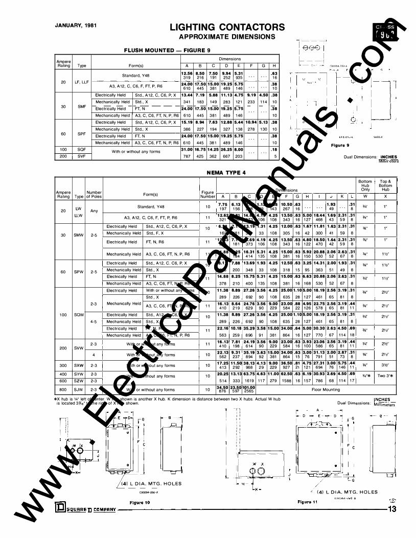
FLUSH MOU NTED - FIGURE 9
Ampere Dimensions
Rating Type Form(s) A B c D E F G H
Standard, Y48 1 2.56 8.50 7.50 9.94 5.31 .63 319 21 6 1 9 1 252 935 . . . . . . 1 6
20 LF, LLF 24.00 17.50 15.00 19.25 5.75 .38 A3, A12, C, C6, F, FT, P, R6 6 1 0 445 381 489 1 46 . . . . . . 1 0
Electrically Held Std., A 1 2, C, C6, P, X 13.44 7.19 5.88 1 1 .13 4.75 9.19 4.50 .38 Mechanically Held Std. , X 341 1 83 1 49 283 1 2 1 233 1 1 4 1 0
30 SMF Electrically Held FT, N 24.00 17.50 15.00 19.25 5.75 .38 . . . . . .
1 e��T L _ _ j � - c- __.:
I
• C30054-33J A
Mechanically Held A3, C, C6, FT, N , P, R6 6 1 0 445 381 489 1 46 1 0
Electrically Held Std., A 1 2, C, C6, P, X 15.19 8.94 7.63 12.88 5.44 10.94 5.13 .38 Mechanically Held Std., X 386 227 194 327 1 38 278 1 30 1 0 � _L_®
60 SPF Electrically Held FT, N 24.00 17.50 Mechanically Held A3, C, C6, Fe N, � R6 6 1 0 445
1 00 SQF With or without any forms 31 .00 16.75 200 SVF 787 425
1 5.00 19.25 5.75 . . .
38 1 489 1 46
14.25 26.25 8.00 . . .
362 667 203
NEMA TYPE 4
.38 . . .
1 0
.18 . . . 5
SADDLE
Figure 9
Dual Dimensions: INCHES M1lhmeters
Bottom Top & Hub Bottom
Ampere Number Figure Dimensions Only Hub
Rating Type of Poles Form(s) Number A B c D E
Standard, Y 48 1 0 7.75 6.13 1 1 .75 1 .13 5.38
LW 1 9 7 1 56 298 29 143 20 Any LLW A3, A12, C, C6, F, FT, P, R6 1 1 1 2.62 7.81 14.69 4.19 4.25
321 198 373 1 06 1 08
Electrically Held Std., A1 2, C, C6, P, X 1 0 6.38 7.1 1 1 3.19 1 .31 4.25
30 SMW 2-5 Mechanically Held Std., F, X 1 62 1 8 1 351 33 1 08
Electrically Held FT, N, R6 1 1 1 2.63 7.1 1 14.69 4.19 4.25 321 1 8 1 373 1 06 1 08
Mechanically Held A3, C, C6, FT, N, P, R6 1 1 14.88 7.25 16.31 5.31 4.25 378 1 84 4 1 4 1 35 1 08
Electrically Held Std., A 1 2, C, C6, P, X 1 0 8.1 3 7.88 13.69 1 .93 4.25
60 SPW 2-5 Mechanically Held Std. , X 206 200 348 33 1 08
Electrically Held FT, N 1 1 14.88 8.25 15.75 5.31 4.25 Mechanically Held A3, C, C6, Fe N, � R6 378 2 1 0 400 1 35 1 08
Electrically Held With or without any forms 1 0 1 1 .38 8.89 27.26 3.56 4.25 Std , X 289 226 692 9 0 1 08
2-3 Mechanically Held A3, C, C6, FT, N, P, R6 1 1 16.13 8.64 24.76 3.56 9.00
4 1 0 2 1 9 629 9 0 229
1 00 saw Electrically Held Std., A 1 2, C, C6, P, X 1 0 1 1 .38 8.89 27.26 3.56 4.25 4-5 Mechanically Held Std., X 289 226 692 90 1 08
Electrically Held FT, N, R6 1 1 22.16 10.18 35.29 3.58 15.00 Mechanically Held A3, C, C6, F e N. � R6 563 259 896 9 1 381
2-3 With or without any forms 1 1 16.13 7.81 24.19 3.56 9.00 200 svw 4 1 0 198 6 1 4 9 0 229
4 With or without any forms 1 0 22.13 9.31 35.19 3.63 15.00
562 237 894 9 2 381
300 sxw 2-3 With or without any forms 1 0 17.25 1 1 .50 38.13 4.1 3 9.00 4 1 3 292 968 29 229
400 SYW 2-3 With or without any forms 1 0 20.25 13.13 63.75 4.63 1 1 .00 600 szw 2-3 5 1 4 333 1 619 1 1 7 279
800 SJW 2-3 With or without any forms 1 0 34.50 23.50 101.00 876 597 2565
*X hub is W' left of center. W hub shown is another X hub. K dimension is distance between two X hubs. Actual W hub is located 3Ylo" to the right of X hub shown.
rr• I ' I I I I I I
I I I I I
1 I
-T l I I I I I I I I I I I I : I I I I I I I I I
F
10.50 267
1 3.50 343
1 2.00 305
1 3.50 343
1 5.00 381
1 2.50 3 1 8
1 5.00 381
25.00 635
23.00 584
25.00 635
34.00 864
23.00 584
34.00 864
36.50 927
62.50 1 588
j tftJJ
�-�I=======J, 1- K-< h) L D I A. MTG . H O LES
C30054-256- F
G H
.63 1 6 . . . .63 5.00 1 6 1 27
.63 1 .67 1 6 42
.63 4.80 1 6 1 22
.63 5.92 1 6 1 50
.63 3.25 1 5 95
.63 6.63 1 6 1 68
1 .10 5.00 28 1 27
.88 4.95 22 1 26
1 .10 5.00 28 1 27
.64 5.00 1 6 1 27
.63 3.93 1 6 1 00
.63 3.00 1 5 76
.81 4.75 21 1 2 1
.63 6.19 1 6 1 57
I J
1 .93 . . . 49
1 8.44 1.69 468 43
1 1 .81 1 .63 300 41
1 8.50 1 .64 470 42
20.88 2.06 530 52
14.31 2.00 363 51
20.88 2.06 530 52
18.19 2.56 461 65
22.75 2.56 578 65
18.19 2.56 461 65
30.30 2.63 770 67
23.06 2.56 586 65
31.13 2.00 79 1 51
27.31 3.00 694 76
30.93 2.69 786 68
K
. . .
2.31 59
2.31 59
2.31 59
2.63 67
1.93 49
2.63 67
3.19 81
3.1 9 81
3.19 81
4.50 1 1 4
3.19 81
2.87 73
5.75 1 46
4.50 1 1 4
Floor Mounting
L w X
.31 3/4" 1" 8
.31 3/4" 1 " 8
.31 3f.." 1"
8
.31 3/4" 1 " 8
.31 3J4'' 1 1/2'' 8
.31 '14" 1 1/211
8
.31 3/4" 1 1/2" 8
.31 '14" 2Yz" 8
.44 '14'' 21/z" 1 1
.31 3/4" 21/2'' 8
.69 '14' 21/2'' 1 8
.44 3/4" 2Vi' 1 1
.31 3/4'' 21/2'' 8
.44 3/4" 3Y2" 1 1
.69 '14"* Two 3''* 1 7
. . INCHES Dual Otmenstons : Mi l l imeters
j A --1 ..--- 0 E - �- D "j I .{:� --:-T J G
T I •
F C
I �/� . Jd
/ " ( 4) L D I A. MTG. H O L ES
��5QUARE D tDM�� ---F-�_u_r_e_10----------------------------�-�_u_r_
e_1_1 ____
,_�_._"_-·_·_�_· ______ � www .
Elec
tricalP
artM
anua
ls . c
om
www . El
ectric
alPar
tMan
uals
. com

Ill LIGHTING CONTACTORS APPROXIMATE DIMENSIONS
NEMA TYPE 1 2
JANU ARY, 1981
Ampere Number Rating Type of Poles
20 LA Any
LLA
30 SMA 2-5
60 SPA 2-5
2-3
1 00 SQA
4-5
2-3 200 SVA
4
300 SXA 2-3
400 SYA 2-3
600 SZA 2-3
800 SJA 2-3
Figure Form(s) Number
Standard, Y48 1 2
A3, A 1 2 , C, C 6 , F, FT. P, R6 1 3
Electrically Held Std., A12, C, C6, P, X 1 2 Mechanically Held Std., F, X
Electrically Held FT, N, R6 1 3
Mechanically Held A3, C, C6, FT. N, P, R6 1 3
Electrically Held Std., A 1 2 , C, C6, P, X
Mechanically Held Std., X 1 2
Electrically Held FT, N Mechanically Held A3, C, C6, FT, N, P, R6 1 3
Electrically Held With or without any forms 1 2 Std., X
Mechanically Held A3, C, C6, FT, N, R R6 1 3
Electrically Held Std., A 1 2 , C, C6, P, X 1 2
Mechanically Held Std., X 1 2
Electrically Held FT, N, R6 1 3
Mechanically Held A3, C , C6, FT. N, P, R6 1 3
With o r without any forms 1 3
With o r without any forms 1 2
With o r without any forms 1 2
With o r without any forms 1 2
With o r without any forms 1 4
' (4} J D I A . MTG. HOLES I i f==1 L� Figure 1 3
A 8 7.75 7.06 1 97 1 79
11.68 7.75 302 1 97
6.38 8.54
1 62 2 1 7
11.88 8.13 302 207
14.88 8.67 378 220
8.13 8.50
206 2 1 6
14.88 7.88
378 200
11.38 9.75
289 222
16.13 8.38 4 1 0 2 1 3
11.38 9.29 289 236
11.38 8.74 289 222
22.15 10.26 563 261
22.15 10.81 563 275
16.13 8.38 4 1 0 2 1 3
22.25 9.87 565 251
17.25 12.13 478 307
20.25 13.13
5 1 4 333
93.00 34.50 2362 876
c D
11.25 1.75 286 44
13.50 3.81 343 97
12.75 1.06
324 27
13.50 3.82 343 97
15.75 5.31 400 1 35
13.25 1.93
337 49 15.75 5.31
400 1 35
20.50 3.56 521 90
26.50 3.56 673 90
25.75 3.56 654 90
25.75 3.56 654 90
35.00 3.58 889 9 1
35.00 3.58 889 91
26.50 3.56 673 90
35.00 3.63 889 92
38.25 4.13 972 1 05
63.75 4.63
1 6 1 9 1 1 7
23.50 597
r-- - 8
I A
I I L
"'
Dimensions
E F G H I
4.25 10.50 .36 2.13 13.13 1 08 267 1 0 54 333
4.25 12.75 .38 4.94 18.12 1 08 324 1 0 1 25 460
4.25 12.00 .38 4.94 18.40
1 08 305 1 0 1 25 467
4.25 12.75 .38 4.44 18.05 1 08 324 1 0 1 1 3 458
4.25 15.00 .38 6.46 21.75 1 08 38 1 1 0 1 64 540
4.25 12.50 .38 3.06 14.75
1 08 3 1 8 1 0 77 375
4.25 15.00 .38 6.41 21.75
1 08 38 1 1 0 1 63 540
4.25 19.75 .38 4.81 18.00
1 08 502 1 0 1 2 1 457
9.00 25.50 .50 3.75 23.44 229 648 1 3 95 595
4.25 25.00 .38 4.69 18.95 1 08 635 1 0 1 1 9 48 1
4.25 25.00 .38 4.25 18.95 1 08 635 1 0 1 08 481
15.00 34.00 .50 4.31 30.88 381 864 1 3 1 09 784
15.00 34.00 .50 4.75 30.88 381 864 1 3 1 2 1 784
9.00 25.50 .50 3.75 23.44 229 648 1 3 95 597
15.00 34.00 .50 3.00 31.00 381 864 1 3 76 787
9.00 36.50 .50 4.87 26.31 229 927 1 3 1 23 668
11.00 62.50 .63 6.81 30.93
279 1 588 1 6 1 73 786
Floor Mounting
- - c � !
� 0 0
Figure 14
1 � 1 '!3: 1 I MASTER r· OUTDOOR LIGHTING CONTROLLER SHORT VERSION
Ampere Rating Description Type Number A B c D E F 30 Disconnect Switch &
Circuit Breaker Types SMC-6 1 , -62 & -81 23.50 15.88 8.42 10.42 20.31 22.38
60 Disconnect Switch & 597 403 2 1 4 265 5 1 6 568 Circuit Breaker Types SPC-61 , -62 & -81
1 00 Disconnect Switch & Circuit Breaker Types saC-61 , -62 & -81 34.53 20.88 8.42 10.42 31.33 33.41
Circuit Breaker Type SVC-81 877 530 2 1 4 265 796 849
200 Disconnect Switch Type SVC-61 & -62
44.37 1 9.88 9.12 11 .10 41.78 43.25 1 1 28 506 232 282 1062 1 1 00
LONG VERSION
Ampere Rating Description Type Number A B c D E F 30 Disconnect Switch &
Circuit Breaker Types SMC-63, -64 & -83 38.88 15.88 8.42 10.42 35.68 37.75
60 Disconnect Switch & 998 403 2 1 4 265 906 959 Circuit Breaker Types SPC-63, -64 & -83
100 Disconnect Switch & Circuit Breaker Types SaC-63, -64 & -83 42.53 20.88 8.42 10.42 39.33 41.41
Circuit Breaker Type SVC-83 1 080 530 2 1 4 265 999 1052
Cond.
G H � K L
7.00 2.18 2.13 2.13
1 78 55 11fz 54 54
7.00 2.18 2 2.68 2.68
1 78 55 � 68 68
7.00 2.18 21fz
2.68 2.68 1 78 55 68 68
Con d .
G H � K L
7.00 2.18 2.13 2.13
1 78 55 11fz 54 54
7.00 2.18 2 2.68 2.68
1 78 55 � 68 68
Knockouts
M N p
2.13 1 - I Y•-
54 Yz-3/4 1 Yz
3.44 Y,-:Y.
1-1 '14-
87 2-2Y,
3.44 Vz-3/4
1 -1 '14-87 2-21/z
Knockouts
M N p
2.13 y,.:y, 1 - 1 V4-
54 1 Vz
3.44 Yz-3/4 1 - 1 V4-
87 2-2Vz
a
Y2-3f4
1 - 1 '14-
1 Vz-2
1 - I Y•-1 '/z-2
a
Y2-3f4
1-1 v.-1 Vz-2
\!_1_DIA MTG HOLES ,..._ , __,
·1 ;:m;::li1n 1 u l ; I
I I I I ; I
I I 4
1 _ . J" l l .L L
. 1 � � 1..-e- ----i
Figure 15
J
.31 8
.31 8
.31
8
.31 8
.31 8
.31
8
.31
8 .31
8
.44 1 1
.31 8
.31 8
.56 1 4
.56 1 4
.44 1 1
.56 1 4
.43 1 1
.69
1 7
200 Disconnect Switch Type SVC-63 & -64
54.37 19.88 9.12 11.10 51.78 53.25 7.00 2.18 21fz
2.68 2.68 3.44 Vz-'1•
1 - 1 '14- 1 - 1 '14-1 383 506 232 282 1 3 1 7 1354 1 78 55 68 68 87 2-2Vz 1Vz-2 Dual Dimensions:
INCHES
Millimeters ��:::0
14------------------------------------ SQUARE D t:DMPRNY IDI www . El
ectric
alPar
tMan
uals
. com
www . El
ectric
alPar
tMan
uals
. com

JANUARY, 1981 LIGHTING CONTACTORS APPROXIMATE DIMENSIONS II
COMBINATION LIGHTING CONTACTORS - ELECTRICALLY AND MECHANICALLY HELD
NEMA TYPE 1 ENCLOSURE - FIGURE 1 6
Ampere Type Rating A
SMG-6_ & !L 9%
244 30
SMG-7 _ & !L 15Y,o 386
SPG-IL& 8_ 10% 270
60
SPG-7_ & 9_ 15Y,. 386
1 00 SQG-6_ & 7_ 15Yis SOG-81 & 91 392
200 SVG-6_ & 7_ 16Y,. SVG-81 & 91 4 1 1
SXG-6_ & 7_ 20'14 5 1 4
300
SXG-81 & 91 20'14 514
400 SYG-81 & 91 36
600 SZG-81 & 91 914
Ampere Type Rating A
SMW-6_ & 8_ 9% 244
30
SMW-7_ & 9_ 15111 384
SPW-6_ & IL 10% 270
60
SPW-7_ & 9_ 15Yo 384
1 00 SQW-6_ & 7_ 15'1a SOW-81 & 91 391
200 SVW-6_ & 7_ 161/o SVW-81 & 91 410
SXW-6_ & 7_ 20'14 514
300
SXW-81 & 91 20'14 514
400 SYW-81 & 91 36
600 SZW-81 & 91 914
Ampere Type Rating
SMA-6_ & IL 30
SMA-7_ & 9_
SPA-6_ & 8_
60
SPA-7_ & !L
1 00 SQA-6_ & 7_ SOA-81 & 91
200 SVA-6_ & 7_ SVA-81 & 91
SXA-6_ & 7_
300
SXA-81 & 91
400 SYA-81 & 91
600 SZA-81 & 91
B c 0 E F
21% 8'1a 63fo 19112 14'71 s 549 2 1 3 1 6 2 495 373
271Y,s 9% 11% 251/4 21112 710 244 295 641 546
251/s 9% 7'1a 23 17 638 244 1 87 584 430
27'r;, 9% 11% 25'14 21112 7 1 0 244 295 641 546
33')1,, 10'}'1s 11'/o 31 22'Y,s 856 271 302 787 576
43Y,. 10% 12% 40Vz 23'Y,s 1 097 270 321 1 029 602
67 15'1z 15 66 zgy,s 1 702 394 381 1676 748
55 1 1 ' Y, s 15 54 27Yls 1 397 303 1 27 1 372 697
80 21y .. 2032 535
Dimensions*
G H I J K
1 1 ;1 s 1 1Y, s 3'1a 2Yts 1)'1s 46 43 86 55 27
2;-1s 2 4 2Y,, 1Y,. 56 51 1 02 66 33
2Vo 2 4 2Y,s l Y1s 54 51 1 02 55 27
zr,s 2 4 zr,s 1Y,s 56 51 1 02 66 33
21Y,s 21Yis 5'1a 3V. 1'1a 75 68 1 37 83 35
2'Y,s 2'Y,s 5'1a 2% 1'1a 75 68 137 67 35
JY,, JY1s 6r .. Yz 90 81 . . . 1 60 1 3
3Y,. JY1s &r,s Yz 90 81 . . . 1 60 1 3
Floor Mounting Enclosure
L
3'/s 98
37/o 98
37/o 98
37/o 98
4'Y,s 1 2 5
47/o 1 24
9'14 235
9'14 235
M
2f,. 56
ZY1s 56
zr,s 56
2Y16 56
2'14 57
2'14 57
2% 67
2o/o 67
N
1'14 32
1112 38
1'14 32
1Vz 38
1Y,. 33
l,o/\s 33
. . .
. . .
NEMA TYPE 4 ENCLOSURE - FIGURE 17 Dimensions*
B c 0 E F G H I J K L
8'1a 233fo 37/o 21)'1s 4'14 22Yz .,. 4 1% 2'1a 14Y,. 2 1 4 594 98 68 108 572 1 6 1 02 4 1 60 364
9% 29'Y, 3% 5Y,s 4'14 28'14 o/o 6'14 2 2% 21Y,. 244 760 98 1 38 1 08 654 1 6 1 7 1 5 1 67 535
9% 27Y,. 3% JY,s 4'/4 26 .,. 41fz 2 2% 16Y,. 244 691 98 81 108 660 16 1 1 4 51 67 421
9o/o 29'Y, 3'/s SY,s 4'14 28'14 o/o 6'4 2 2% 21Y,. 244 760 98 1 38 1 08 654 16 171 51 67 535
10Y,. 36Y,. 41Y,s 3Y,. 9 35 .,. 5Y,. 2Y,. 3Y,s 22Y,. 268 919 1 25 81 229 889 1 6 1 32 65 81 564
10Y,. 45'}'1s 4'/s 3Y16 9 44Vz o/o 4'/s 2Y,s 3Y,. 23 268 1 1 60 1 24 90 229 1 1 30 1 6 1 24 65 81 584
1 5112 67Vo 9'14 2% 15 66 y,, &,o/16 3 3Vz 29Y,s 394 1 705 235 67 381 1 676 1 4 1 60 76 89 748
1 1 ' ;1 s 551/s 4'Y1s 2% 15 54 y,, &Y,s 3 3Vz 27Y,s 303 1400 1 25 67 381 1 372 14 1 60 76 89 697
21Y,. 88 535 2235
Floor Mounting Enclosure
NEMA TYPE 12 ENCLOSURE - FIGURE 18 Dimensions*
A 8 c 0 E F G
9% 8'1a 23'14 3'/s Z'Y1s 4'14 221fz 244 2 1 3 591 98 68 1 08 572
15Y,. 11 29112 37/a 5}'1s 41J4 28'14 386 279 749 98 1 38 1 08 730
10% 9Y,. 26'14 3% 3Y,. 41/4 26 270 243 679 98 81 1 08 660
15Y,. 11 29'!2 3% SY,s 4'14 28'14 386 279 749 98 1 38 1 08 730
1 5Y,s 10'Y,s 36 41 7"16 3'14 9 35 392 278 914 1 25 83 229 889
16Y,. 10Y,. 45Yz 4'/s 3o/a 9 44'12 4 1 1 268 1 1 56 1 24 92 229 1 1 30
20'14 15112 67 9V. 2% 15 66 5 1 4 394 1 702 235 67 381 1 676
201/4 1 1 1Y,s 55 4'Y,s 2% 15 54 5 1 4 303 1 397 1 25 67 381 1 372
0
'I• 22
,r,s 24
'Is 22
'Y,s 24
' Y.. s 24
'l'ls 24
. . .
. . .
w
%''Hub
%" Hub
%" Hub
%" Hub
3f4''Hub
%" Hub
%" Hub
3/4" Hub
. . .
H
'Ia 1 0
'Ia 1 0
'Ia 1 0
'Ia 1 0
v. 1 3
y, 1 3
v. 1 3
'12 1 3
36 21Y,. 80 Floor Mounting Enclosure 914 535 2032
Top & Bot. Sides
w
112-%
1 - 1 %
1 - 1 %
1 - 1 %
1 - 1 % 2-2Yz
2112
'14
'14
. . .
I
4Yis 1 1 3
77'1s 183
X
1f2-%
Yz-3/4
1f2-%
1f2-:Y4
Vz-¥4
Yz-3/4
3
3
. . .
X
1 " Hub
1 W' Hub
1 Yz" Hub
1 Yz"Hub
2Vz'' Hub
2Vz" Hub
3Yz''Hub
3Yz" Hub
. . .
J
y
y,
y,
y,
y,
y,
y,
. . .
. . .
. . .
14Y,, 1 1 0
23Y16 595
417'16 16Y,. 1 25 421
7Y16 2JY,s 1 83 595
sru; 22Y,, 1 32 567
5Y,. 23 1 35 584
6Y,. 29Y,s 1 60 748
6Y,. 27Y,s 1 60 697
*Dimensions are the same for Form FT (standard control transformer), Form FT-1 1 (100 VA extra capacity) and Form FT-12 (200 VA extra capacity).
r,-.-li t' �+ 1 1 --
Figure 16 NEMA Type 1 Enclosure
�Hr�·-:l h---�-"'"--I \ ,,_
Figure 17 NEMA Type4 Enclosure
�'tl;-� c
G
I
\,,.__
Figure 18 NEMA Type 12 Enclosure
Dual Dimensions: INCHES
Millimeters
IIJI S Q U A R E D CDMPANY----------------------------------------------------------------------- 15 www . El
ectric
alPar
tMan
uals
. com
www . El
ectric
alPar
tMan
uals
. com

I • • I S Q U A R E D CO M PA NY
1/81 TP Printed in U.S.A. www . El
ectric
alPar
tMan
uals
. com
www . El
ectric
alPar
tMan
uals
. com

JUNE, 1966 Supersedes Price Sheet 8903 Page 1, dated October, 1964
CLASS 8 9 0 3 Price Sheet PAGE 1
AC LIGHTING CONY ACTORS FOR TUNGSTEN, FLUORESCENT, and MERCURY ARC LAMPS
A C 4aO VOLTS MAXIMUM LINE VOLTAGE DC 250 VOLTS MAXIMUM LINE VOLTAGE
COI L - 24-4aO VOLTS AC
General Purpose Enclosure
Ampere No. of NEMA Type 1 Ratings Poles
Type Price
2 MG-1 $ 33. 30 3 MG-2 36.
4 MG-3 44.
2 PG-1 6a. 60 3 PG-2 72.
4 PG-3 90. ELEC. H E LD 2 QG-1 U2.
(Without 100 3 QG-2 120. Interlock) 4 QG-3 148.
2 VG-1 264. 200 3 VG-2 2a2.
4 VG-3 376.
2 XG-1 ssa. 300 3 XG-2 600.
4 XG-3 1U5.
2 MG-10 44. 30 3 MG-11 47.
4 MG-12 50.
2 PG-10 104. 60 3 PG-11 10a.
MEC H. 4 PG-12 12a. H E LD (With 2 QG-10 146. Coil 100 3 QG-11 154.
Clearing 4 QG-12 1a4. Contacts)
2 VG-10 374. 200 3 VG-11 422.
4 VG-12 516.
2 XG-13 654. 300 3 XG-14 71a.
4 XG-15 1165.
Flush Mounting General Purpose
Enclosure with Plaster Adjustment
Type
MF-1 MF-2 MF-3
PF-1 PF-2 PF-3
QF-1 QF-2 QF-3
VF-1 VF-2 VF-3
. . . . . .
. . . . . .
. . . . . .
MF-10 MF-11 MF-12
PF-10 PF-11 PF-12
QF-10 QF-11 QF-12
VF-10 VF-11 VF-12
. . . . . . · · · · · · . . . . . .
Price
$ 45. 48. 56.
a3. a7.
105.
131. 139. 167.
294. 312. 406.
. . . . .
. . . . .
. . . . .
62. 65. 6a.
124. 12a. 14a.
1ao. 18a. 21a.
424. 472. 556.
. . . . .
. . . . .
. . . . .
Prices do not include push button stations. Prices do not include holding circuit interlock.
ORDERING INFORMATION REQUIRED 1 -Ciass and Type number.
2-Voltage and frequency of coil.
3-Additions or special features required.
Additions and Special Features-Refer to Tab " Additions and Special Features11
MAXIMUM WIRE SIZE
Contactors will accept copper wire of the maximum sizes indicated below :
C O NTACT O R RATI NG
30 A. 60 A. 100 A. 200 A. 300 A.
1-#8 1-#4 1-#1/0 1-350 2-350 MCM MCM
Dust-tight Water-tig ht Enclosure Enclosure Open Type
NEMA Type 12 NEMA Type 4
Type
MA-1 MA-2 MA-3
PA-1 PA-2 PA-3
QA-1 QA-2 QA-3
VA-1 VA-2 VA-3
XA-1 XA-2 XA-3
MA-10 MA-11 MA-12
PA-10 PA-11 PA-12
QA-10 QA-11 QA-12
VA-10 VA-11 VA-12
XA-13 XA-14 XA-15
Price Type Price Type
$ 45. MW-1 $ 69. M0-1 4a. MW-2 72. M0-2 56. MW-3 80. M0-3
---�-
90. PW-1 140. P 0-1 94. PW-2 144. P 0-2
112. PW-3 190. P 0-3 -----
138. QW-1 214. Q 0-1 146. QW-2 222. Q0-2 174. QW-3 278. Q0-3
350. VW-1 438. V0-1 36a. VW-2 456. V0-2 492. VW-3 622. V0-3
----
77a. XW-1 77a. X 0-1 a20. XW-2 a20. X0-2
1357. XW-3 1357. X0-3
a2. MW-10 ao. M0-10 as. MW-11 a3. M0-11 a a. MW-12 a6. M0-12
152. PW-10 156. P0-10 156. PW-11 1ao. P 0-11 1a4. PW-12 22a. P 0-12
204. QW-10 24a. Q 0-10 212. QW-11 256. Q 0-11 266. QW-12 314. Q0-12
460. VW-10 54a. V0-10 soa. VW-11 596. V 0-11 594. VW-12 690. V0-12
827. XW-13 a74. X0-13 a45. XW-14 93a. X 0-14
1406. XW-15 140S. X0-15
200 Ampere electrically held lighting contactor
Price
$ 31. 34. 42.
sa. 62. ao.
92. 100. 12a.
222. 240. 334,
4a1. 523. 961.
42. 45. 4a.
96. 100. 120.
12a. 136. 166.
316. 342. 436.
530. 54a.
1010.
---------------------------;S�Q�U�A�RE D CD M PANY ---------------------------Prices Subject to Change without Notice. ·::;:· SCHEDULE DS-1 DISCOUNTS www .
Elec
tricalP
artM
anua
ls . c
om
www . El
ectric
alPar
tMan
uals
. com

www . El
ectric
alPar
tMan
uals
. com
www . El
ectric
alPar
tMan
uals
. com
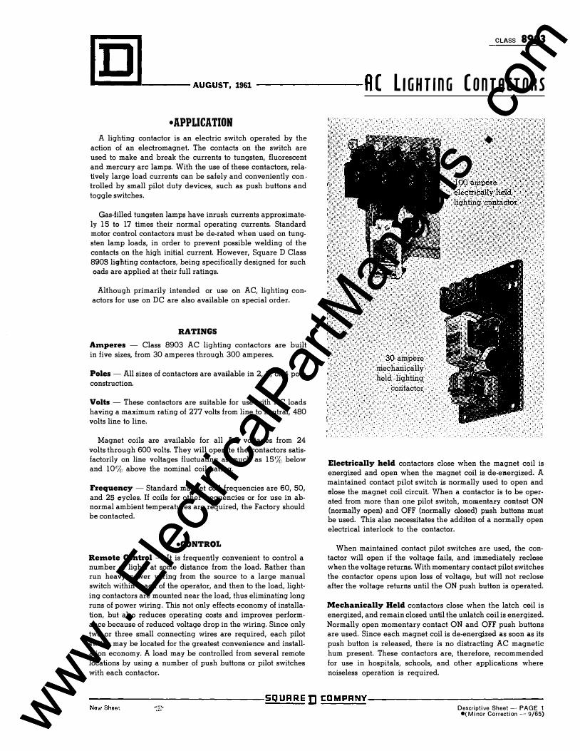
C LASS 8903
�� ��----AUGUST, 1961 ----R ( L I G H T i n G ( O n T A C T O R S
• APPLICATION A lighting contactor is an electric switch operated by the
action of an electromagnet. The contacts on the switch are used to make and break the currents to tungsten, fluorescent and mercury arc lamps. With the use of these contactors, relatively large load currents can be safely and conveniently con · trolled by small pilot duty devices, such as push buttons and toggle switches.
Gas-filled tungsten lamps have inrush currents approximately 1 5 to 17 times their normal operating currents. Standard motor control contactors must be de-rated when used on tungsten lamp loads, in order to prevent possible welding of the contacts on the high initial current. However, Square D Class 8903 lighting contactors, being specifically designed for such oads are applied at their full ratings.
Although primarily intended or use on AC, lighting conactors for use on DC are also available on special order.
RATINGS
Amperes - Class 8903 AC lighting contactors are built in five sizes, from 30 amperes through 300 amperes.
Poles - All sizes of contactors are available in 2, 3, or 4 pole construction.
Volts - These contactors are suitable for use with AC loads having a maximum rating of 277 volts from line to neutral, 480 volts line to line.
Magnet coils are available for all AC voltages from 24 volts through 600 volts. They will operate the contactors satisfactorily on line voltages fluctuating as much as 1 5 % below and 10% above the nominal coil rating.
Frequency - Standard magnet coil frequencies are 60, 50, and 25 cycles. If coils for other frequencies or for use in abnormal ambient temperatures are required, the Factory should he contacted.
•CONTROL
Remote Control - It is frequently convenient to control a number of lights at some distance from the load. Rather than run heavy power wiring from the source to a large manual switch within reach of the operator, and then to the load, lighting contactors are mounted near the load, thus eliminating long runs of power wiring. This not only effects economy of installation, but also reduces operating costs and improves performance because of reduced voltage drop in the wiring. Since only two or three small connecting wires are required, each pilot switch may be located for the greatest convenience and installation economy. A load may be controlled from several remote locations by using a number of push buttons or pilot switches with each contactor.
30 ampere mechanically held lighting
contactor
100 ampere electrically held lighting contactor
Electrically held contactors close when the magnet coil is energized and open when the magnet coil is de-energized. A maintained contact pilot switch is normally used to open and slose the magnet coil circuit. When a contactor is to be operated from more than one pilot switch, momentary contact ON (normally open) and OFF (normally closed) push buttons must be used. This also necessitates the additon of a normally open electrical interlock to the contactor.
When maintained contact pilot switches are used, the contactor will open if the voltage fails, and immediately reclose when the voltage returns. With momentary contact pilot switches the contactor opens upon loss of voltage, but will not reclose after the voltage returns until the ON push button is operated.
Mechanically Held contactors close when the latch coil is energized, and remain closed until the unlatch coil is energized. Normally open momentary contact ON and OFF push buttons are used. Since each magnet coil is de-energized as soon as its push button is released, there is no distracting AC magnetic hum present. These contactors are, therefore, recommended for use in hospitals, schools, and other applications where noiseless operation is required.
��-----------------------;S�Q�U�A�R�E D CD M PANY---------------------------
New Sheet ·:�:· Descriptive Sheet - PAGE 1 •(Minor Correction - 9/65) www .
Elec
tricalP
artM
anua
ls . c
om
www . El
ectric
alPar
tMan
uals
. com

8903 CLASS
� R C L I G H T i n G C o n r R c r o R s----- AUGUST, 1961 --·
60 ampere mechanically held lighting contactor
with coil clearing contacts
General purpose enclosure for 30 ampere electrically held lighting contactor
Coil cleadng contacts should be added to mechanically held contactors controlled by maintained contact pilot switches. These contacts de-energize the magnet coils after operation of the contactor has been completed. The desirable feature of complete absence of AC magnetic hum is thus retained.
CONSTRUCTION Class 8903 contactors in all sizes are the vertical action type,
employing double break silver contacts which do not corrode and never need cleaning or dressing.
All contactors are provided with shading coils, embedded in the magnet frame, to reduce the AC hum to a minimum.
FEATURES Accessibility-One of the foremost features of Square D lighting contactors is accessibility for maintenance or repair.
All electrical equipment needs maintenance and replacement attention at regular intervals. That equipment which is easy to inspect and maintain receives more maintenance service and enjoys longer life. Thus, double economy is realized. All renewable parts of Square D lighting contactors can be inspected with a minimum of time and labor, using only a screwdriver and pliers.
Some of the outstanding features of Class 8903 contactors are:
I . Contacts replaceable without disturbing line and load wiring.
2. All parts front-mounted. It is unnecessary to remove the contactor from its enclosure for maintenance or replacement of any part.
3. Molded coils. Coils are less subject to mechanical injury. Coils operate cooler because of better heat transfer, thus last longer.
Class 8903 contactors are available with many special features, some of which are:
Push button in cover-Class 8903 contactors in all sizes are available with ON-OFF momentary contact push buttons mounted in the cover of the enclosure for external operation. (Electrically held contactors require the addition of a normally open electrical interlock) . Where this arrangement is convenient from the operating standpoint, installation economies are obtained through the elimination of a separate push bntton station and its wiring. Separately mounted push buttons may also be connected in parallel with the one included with the contactor.
Electrical Interlocks-are available in arrangement and number to satisfy every practical need. They will be installed at the Factory if specified on the order, but can be easily installed in the field on all contactors. Interlocks for installation by users are listed in Catalog Section Class 9999. For 30 ampere lighting contactors, use the same interlocks as listed for Size I starters; for 60 ampere contactors, use Size 2 interlocks; for 1 00 ampere contactors, use Size 3 interlocks; for 200 ampere contactors, use Size 4 interlocks and for 300 ampere contactors use Size 5 interlocks.
ENCLOSURES General Purpose Enclosures-NEMA 1-are intended to prevent accidental contact with live parts are suitable for general indoor use where normal atmospheric conditions prevail.
These surface mounting enclosures are constructed of heavy sheet steel, finished in gray enamel. All covers have latches with provisions for padlocking. ON-OFF momentary contact push buttons may be easily mounted in the covers of 30 through 200 ampere contactor enclosures, by removing either a cover knockout or cover plate.
���----�---------------:S�Q�U�A�RE D CD M P A NY--------------------------
PAGE 2 - Descriptive Sheet ·:�:· New Sheet www . El
ectric
alPar
tMan
uals
. com
www . El
ectric
alPar
tMan
uals
. com

AUGUST, 1961 New Sheet ( Minor Revision - 11 /65)
AC LIGHTING CONY ACTORS Approximate Dimensions - Not for Construction
Figure 1 Figure 2
Figure 4
mr==�� tcJ �A}l �Cj
�___:____,� . .. +. F "� I� D � _lf " "" " Figure 7 Figure 8
APPROXI MATE DI MENSIONS
Figure 5
CLASS 8 9 0 3 Dimension Sheet PAGE 1
Figure 3
F
Figure 9
CLASS 8903
i i ELECTRICALLY HELD MECHANICALLY HELD
i I
Enclosure I Di-men-sion
A B c
Open D Type E
F
I G H
I 30 60 100
Amp. I Ampere Ampere
Fig. 1 I Figure 2 Figure 3
2 to 4 I 2 or 3 1 4 2 or 3 1 4 Poles Pole Pole Pole Pole --- --- ---· --- ---
5� G 7%: 6Ys 93.16 7 Y. 10>4 10>4 l l Ys l l Ys 31\.{, 4 %; 4%: 5 % 5 % 6_Y. 9_Y. 9_Y. 10>4 10>4 1 1 .V. 1 _Y. 2 2
l{, � � Vsz 9/32 . . . . 'Yt6 % 1 u, 1 l.{o . . . . . . . . . . 3 3
200 Ampere
Figure 4
2 or 3 4 Pole Pole
7 9% 12% 12%
6Ysz 6%', 1 1 1 1
2 2 � 7,{6 29-11 ��
. . . ------- ---- --- ---
Fig. 7 Di- ---
NEMA Type 1 men- 2 to 4 Surface sion Poles
Mounting 1-General A 6'\{, Purpose B 9 %
Enclosure c 4_Y. D 4% E 6 %
I F >4
NOTE - Dimensions are in inches.
Figure 7 Figure 7 Fig. 7
2 or 3 1 4 2 or 3 Pole Pole Pole --- --- ---8% 10%; 10Ys
14%: 14%; 1 9Y. 5 %; 5%; 7 6Ys 6Ys 8%:
1 1 15/if; 1 ! 1% 16>4 �6 %; 13/:(z
---4 2 or 3
Pole I Pole --- ---12% 14>4 19Ys 25 %
7 Ys 7 % 10 12 1 6 2211�6
9 / /32 1�2
Fig. 7
4 Pole
14>4 25 %
7 % 1 2 2211�6 17,£2
300 Ampere
Figure 9
2 Pole
3 I 4 Pole Pole
7>4 10>4 23_Y. 23 _Y.
9"11; 9C{, 20% 20%
2 2%; � 9,16
l l.{o 1 \.{, . . . . . . . .
Figure 8 2 I 3
Pole Pole
1 1 % 17% 39 39 13Ys 13 Ys s.v. 13 37 37 ll/{f, 111r, I
13_Y. 23_Y.
9% 20�16
2 %; %
1l.{o
4 Pole
17% 39 1 3 Ys 13 37 11{1,
30 ' GO Ampere Amp. I Fig. 5 ��
2 to 4 1 2 or 3 4 Poles Pole Pole
5_Y. 10>4
3 Y s 9_Y. 4� �2
% . .
Fig. 8
2 to 4 Poles
7 % 13 %
5 Ys 5_Y.
l l _Y. 9/{�
6>4 7'�' 12%; 12%;
4Ys 4Ys 12 12
5_Y. 7% � � % %
. . . . . . .
Figure 8 2 or 3 ' 4 Pole Pole --- ---9% l l _Y.
1 8 Y. 18Y. 6Ys 6Ys 7:Y:! 9
1 6 1G �2 �
100 Ampere
Figure 5
2 or 3 1 4 Pole Pole --- ---
7y,ij 1411/il;
513,16 13 Ys
6 % 9/gz � . . . .
9%; 14ll_{o
51% 13 Ys
81% � U6
. . . .
Figure 8
2 or 3 4 Pole Pole
10 Ys 12Y. 20%; 20%;
7 Ys 7 Ys 8%; 10
18% 18% 9A2 5/['6
200 •Ampere
Figure 5
2 or 3 4 Pole Pole
7.V. 9 %; 177/tl; 1 7 7�,
6 %; 6%; 1 1 1 1
�{o I
�{(;
Figure 8 2, :1 or 4
J>oJe
14_Y. 25 % 81.�{2 12 2211/l'u li/{2
• Rev ised.
----------------------------S Q U A RE D CDMPANY----------------------------·:;':· Dimensions Subject to C hange without Notice. www .
Elec
tricalP
artM
anua
ls . c
om
www . El
ectric
alPar
tMan
uals
. com

www . El
ectric
alPar
tMan
uals
. com
www . El
ectric
alPar
tMan
uals
. com