class µ7: project update: toys in the...
TRANSCRIPT

Chapter 25N
Class µ7: Project Update: Toys in the
Attic
REV 11; April 29, 2013.
1Revisions: add E-ink mention to displays (4/13).
1
2 Class µ7: Project Update: Toys in the Attic
Contents
25NClass µ7: Project Update: Toys in the Attic 1
25N.1One More Microcontroller that may interest you . . . . . . . . . . . . . . . . . . . . . . . . . . . . . . . . . . . . . . . . 225N.2Projects: An Invitation and a Caution . . . . . . . . . . . . . . . . . . . . . . . . . . . . . . . . . . . . . . . . . . . . . . 425N.3Some Pretty Projects . . . . . . . . . . . . . . . . . . . . . . . . . . . . . . . . . . . . . . . . . . . . . . . . . . . . . . 5
25N.3.1Laser character display . . . . . . . . . . . . . . . . . . . . . . . . . . . . . . . . . . . . . . . . . . . . . . . . . 525N.3.2Sound Source Detector . . . . . . . . . . . . . . . . . . . . . . . . . . . . . . . . . . . . . . . . . . . . . . . . . 6
25N.3.3Computer-driven Etch-a-Sketch . . . . . . . . . . . . . . . . . . . . . . . . . . . . . . . . . . . . . . . . . . . . 725N.3.4A Giant Etch-a-Sketch . . . . . . . . . . . . . . . . . . . . . . . . . . . . . . . . . . . . . . . . . . . . . . . . . 8
25N.3.5An Attempted Insect . . . . . . . . . . . . . . . . . . . . . . . . . . . . . . . . . . . . . . . . . . . . . . . . . . 925N.4Some Other Memorable Projects . . . . . . . . . . . . . . . . . . . . . . . . . . . . . . . . . . . . . . . . . . . . . . . . 1025N.5X-Y Scope Displays . . . . . . . . . . . . . . . . . . . . . . . . . . . . . . . . . . . . . . . . . . . . . . . . . . . . . . 10
25N.5.1Hardware . . . . . . . . . . . . . . . . . . . . . . . . . . . . . . . . . . . . . . . . . . . . . . . . . . . . . . . . 1025N.5.216 X 16 Dot Array Hardware . . . . . . . . . . . . . . . . . . . . . . . . . . . . . . . . . . . . . . . . . . . . . . 10
25N.5.3Connect the Dots . . . . . . . . . . . . . . . . . . . . . . . . . . . . . . . . . . . . . . . . . . . . . . . . . . . . 1125N.5.4256 X 256 Dot Array . . . . . . . . . . . . . . . . . . . . . . . . . . . . . . . . . . . . . . . . . . . . . . . . . . 11
25N.5.5Size Control; Zoom . . . . . . . . . . . . . . . . . . . . . . . . . . . . . . . . . . . . . . . . . . . . . . . . . . 1225N.5.6True Vector Drawing: Position-Relative . . . . . . . . . . . . . . . . . . . . . . . . . . . . . . . . . . . . . . . . 14
25N.5.7Animation . . . . . . . . . . . . . . . . . . . . . . . . . . . . . . . . . . . . . . . . . . . . . . . . . . . . . . . 1525N.6Computed Drawing . . . . . . . . . . . . . . . . . . . . . . . . . . . . . . . . . . . . . . . . . . . . . . . . . . . . . . . 1525N.7Laser XY Display . . . . . . . . . . . . . . . . . . . . . . . . . . . . . . . . . . . . . . . . . . . . . . . . . . . . . . . 16
25N.8Charmingly Simple LED Display . . . . . . . . . . . . . . . . . . . . . . . . . . . . . . . . . . . . . . . . . . . . . . . 1625N.9Vehicles . . . . . . . . . . . . . . . . . . . . . . . . . . . . . . . . . . . . . . . . . . . . . . . . . . . . . . . . . . . . 17
25N.9.1Tractors with Independent Drive for Two Wheels . . . . . . . . . . . . . . . . . . . . . . . . . . . . . . . . . . . 1725N.9.2A Computer-Steered Toy Car . . . . . . . . . . . . . . . . . . . . . . . . . . . . . . . . . . . . . . . . . . . . . . 18
25N.10A Perennial Heartbreaker: Inverted Pendulum . . . . . . . . . . . . . . . . . . . . . . . . . . . . . . . . . . . . . . . . . 1925N.10.1Fearless Pioneer Tried 2-dimensions . . . . . . . . . . . . . . . . . . . . . . . . . . . . . . . . . . . . . . . . . . 1925N.10.2One-dimensional Inverted Pendulum . . . . . . . . . . . . . . . . . . . . . . . . . . . . . . . . . . . . . . . . . . 20
25N.11Games . . . . . . . . . . . . . . . . . . . . . . . . . . . . . . . . . . . . . . . . . . . . . . . . . . . . . . . . . . . . . 2225N.11.1Pacman on scope screen . . . . . . . . . . . . . . . . . . . . . . . . . . . . . . . . . . . . . . . . . . . . . . . . 22
25N.11.2Asteroids on a Scope Screen . . . . . . . . . . . . . . . . . . . . . . . . . . . . . . . . . . . . . . . . . . . . . . 2225N.11.3Other Great Games . . . . . . . . . . . . . . . . . . . . . . . . . . . . . . . . . . . . . . . . . . . . . . . . . . . 23
25N.12Devices, Gadgets . . . . . . . . . . . . . . . . . . . . . . . . . . . . . . . . . . . . . . . . . . . . . . . . . . . . . . . . 2325N.12.1Mechanical: motors, etc. . . . . . . . . . . . . . . . . . . . . . . . . . . . . . . . . . . . . . . . . . . . . . . . . 23
25N.12.2Transducers . . . . . . . . . . . . . . . . . . . . . . . . . . . . . . . . . . . . . . . . . . . . . . . . . . . . . . 2425N.12.3Displays . . . . . . . . . . . . . . . . . . . . . . . . . . . . . . . . . . . . . . . . . . . . . . . . . . . . . . . . 2725N.12.4Interface Devices . . . . . . . . . . . . . . . . . . . . . . . . . . . . . . . . . . . . . . . . . . . . . . . . . . . . 27
25N.13Stepper Motor Drive . . . . . . . . . . . . . . . . . . . . . . . . . . . . . . . . . . . . . . . . . . . . . . . . . . . . . . 2825N.13.1Generally . . . . . . . . . . . . . . . . . . . . . . . . . . . . . . . . . . . . . . . . . . . . . . . . . . . . . . . 28
25N.13.2Using the stepper motor . . . . . . . . . . . . . . . . . . . . . . . . . . . . . . . . . . . . . . . . . . . . . . . . 2925N.14Project Ideas . . . . . . . . . . . . . . . . . . . . . . . . . . . . . . . . . . . . . . . . . . . . . . . . . . . . . . . . . . 30
25N.14.1Nifty Recent Projects, for your inspiration . . . . . . . . . . . . . . . . . . . . . . . . . . . . . . . . . . . . . . . 3025N.14.2New & Untested . . . . . . . . . . . . . . . . . . . . . . . . . . . . . . . . . . . . . . . . . . . . . . . . . . . . 30
25N.15Two Programs that Could be Useful: LCD, Keypad . . . . . . . . . . . . . . . . . . . . . . . . . . . . . . . . . . . . . . 31
25N.15.1LCD driver; Keypad scanner . . . . . . . . . . . . . . . . . . . . . . . . . . . . . . . . . . . . . . . . . . . . . . 31
25N.1 One More Microcontroller that may interest you
We’ll not have time to try these “PSOC” devices, but you may at some later time want to try them These
integrate a microcontroller (an 8051, in the instance shown below) with analog parts that can be configured

Class µ7: Project Update: Toys in the Attic 3
by downloaded code. These parts, which Cypress Semiconductor calls, a bit grandiosely, “Pogrammable
System on a Chip,” begin to permit an analog equivalent of the programmability you are accustomed to see
in PALs.
We include, below, a few pages from a PSOC data sheet, describing their integration of a rather standard
controller with the novelty of a couple of operational amplifiers, as well as comparators (a feature that is
not new; the SiLabs ’410 includes one). It is not only the operational amplifier that is integrated; that would
hardly be much of an achievement. It is also the configuration of the op amp circuit that is to some extent pro-grammable: the op amp can be configured for various gains, to form an I-to-V (“transimpedance”) converter,
and even a sample-and-hold.
We expect that this is just a modest beginning to a richer set of programmable analog functions. Already,
these parts have enjoyed commercial success.
Figure 1: PSOC Block Diagram: 8051 plus standard digital parts and converters—plus Op Amps

4 Class µ7: Project Update: Toys in the Attic
The analog parts are shown in a little more detail in the block diagram of fig. 2:
Figure 2: PSOC Block Diagram showing Analog Parts
25N.2 Projects: An Invitation and a Caution
Projects are optional. Don’t feel obliged to undertake one. But they can be heaps of fun. To help youconceive a project, here is some information on gadgets and ideas that might inspire a project builder, along
with sketches of some great projects of yester-term.
General Advice:
• Try your ideas on one of us, early in the process. We can steer you away from the impossibly grandiose;
less often, we can tell you that your invention is too modest to be called a “project.”
• Choose a project appropriate to the little computer, not a project that’s better done on a full-scale
computer. That means, among other points, keep the programming modest. It also may mean ‘make a
motor spin; don’t do computations and then display a number,’ for example.
• Try to include some hardware additions along with your invented software. This point is partly a
corollary of the preceding point, but also reflects a second aim: the project often works to help you
firm up your grip on ideas, by letting you do some designing. It can serve as a sort of review. A broader
review is better than a pure exercise in programming.
• Make your project incremental rather than all-or-nothing. For example, the people who built the
computer-controlled RC car started out proposing a game in which the computer would make one
car chase a second car that was controlled by a human. We persuaded them to try this in stages...
– first, see if the computer could control the car (pretty easy);
– second, see if their ultrasonic ears could get significant information from the delay times between
the car’s ultrasonic squeak and the reception at the computer’s three ’ears.’
– third, build the link between the little computer and the PC
Class µ7: Project Update: Toys in the Attic 5
• You get the idea. In fact, these students were able to get most of their original scheme to work. But
tasks nearly always take longer than one expects, and we want you to feel satisfied with a modest
project, rather than frustrated by a grand one.
25N.3 Some Pretty Projects
Later in these notes, beginning at § 25N.4 on page 10, we mention some memorable past projects. Beginning
at § 25N.12 on page 23 we list some hardware that we can offer to a builder. In this preliminary section,
in hopes of exciting ambitions, we offer a glimpse of some of the more photogenic gizmos produced by theenergetic minority who find time for a project.
25N.3.1 Laser character display
This student persevered despite our advice to try something less ambitious. What he proposed seemed much
too complicated: to spin a set of differently-inclined mirrors, letting a laser switch On and Off appropriately,
so as to produce a projection of characters on a screen.
We gasped when he brought the thing in. We also felt uneasy for his beautiful machine, noting that it was
mounted with plasticene. Even the aiming of the laser was accomplished by pushing the plasticene blob this
way or that.
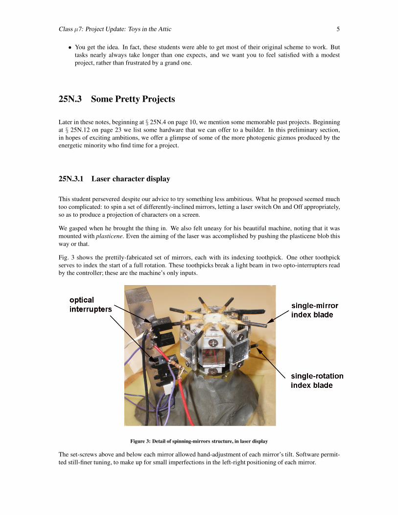
Fig. 3 shows the prettily-fabricated set of mirrors, each with its indexing toothpick. One other toothpick
serves to index the start of a full rotation. These toothpicks break a light beam in two opto-interrupters readby the controller; these are the machine’s only inputs.
Figure 3: Detail of spinning-mirrors structure, in laser display
The set-screws above and below each mirror allowed hand-adjustment of each mirror’s tilt. Software permit-
ted still-finer tuning, to make up for small imperfections in the left-right positioning of each mirror.

6 Class µ7: Project Update: Toys in the Attic
Fig. 4 shows the machine in action.
Figure 4: Detail of spinning-mirrors structure, in laser display
The text is illegible in this photo—but was perfectly legible in life. It spelled out a long message, beginning with the name
of the course and finishing with the name of the author, Mr. Uscinski. He deserves to be remembered for this machine!
25N.3.2 Sound Source Detector
This project, done with the ‘Big Board’ version of the computer rather than with a single-chip implementation
as in the other cases, came together with surprising speed: in one long afternoon. It survives partly becauseits builders took the trouble to mount it on a big piece of foamcore.2
It displays the compass heading of a loud sound (usually a handclap). The computer is fed three binary sig-nals, taken from three microphone amplifiers and comparators. The microphones are separated by a handful
of centimeters. The computer gets an approximate direction by noting simply the order in which the com-
parators fire. It gets a more detailed reading in one 60-degree pie-slice—just one quadrant because the student
designers decided they should call it a day and moved on to reviewing for exams. It gets that detailed reading
by noting time delay among the three microphones.
Fig. 5 shows the three microphone boards, and the computer board reading “320,” the compass heading of a
recent handclap.
2The builders: Sian Kleindienst and *.

Class µ7: Project Update: Toys in the Attic 7
Figure 5: Sound source detector project
Fig. 6 shows the circuit with a scope displaying the staggered arrival of the handclap that produced a particular
compass reading.
Figure 6: Sound source detector showing scope display of microphone-comparator inputs
25N.3.3 Computer-driven Etch-a-Sketch
This project implemented a notion less original than the ones above: let two stepper motors turn the knobs
of a child’s Etch-a-Sketch display. The mechanical part of the task was a pesky challenge, because the toy’s
knobs’ resistance to turning is considerable, and the shafts wobble a bit. The gadget did, however, laboriously
spell out “P 1 2 3.”

8 Class µ7: Project Update: Toys in the Attic
Figure 7: Etch-a-sketch driven by two stepper motors
That doesn’t sound like much of an achievement, perhaps. But having witnessed the struggles that came
before, as the designers implemented the stepper driver in software, including the refinement of half-step, we
were thoroughly impressed when we saw our course number emerge on the screen (not shown in fig. 7 on theprevious page, unfortunately).
25N.3.4 A Giant Etch-a-Sketch
A somewhat similar drawing machine was fashioned, again using two stepper motors, from a massive X-Y
table that we rescued from the trash. The resolution of this machine is fantastically fine—but this projectapplied it to writing a short message, in the manner of the toy etch-a-sketch.
Figure 8: Big X-Y table driven in the manner of the etch-a-sketch

Class µ7: Project Update: Toys in the Attic 9
A later student added a solenoid that permitted the pen to lift. It would be nice to see this excellent X-Y table
used to rout copper so as to lay out a printed circuit board. But the software for such a thing would be way
out of line for the purposes of our students’ projects.
25N.3.5 An Attempted Insect
Not all projects succeed, as you might guess. But failures after intelligent effort please us, too. Here is one:
a nicely-fabricated 6-legged insect:
Figure 9: A 6-servo insect, in need of further evolution
Each leg is driven by a servo-motor (the sort that takes an angular position determined by the width of a
pulse). This insect carries its battery, a flat Polaroid 6-volt type, in its belly. The tin can on top regulates that
to 5 Volts.
The designers discovered, when they set their machine to walking, that insects need knees—or some other
scheme that lets a foot rise and fall from the ground. The creature of fig. 9 was unable to walk, as designed;
it could only raise and lower its body, in the manner of a person salaaming. It could not proceed forward or
backward.
The designers of the Radio Shack insect of fig. 10 understood that the creature needed to be able to lift some
of its feet while they moved forward, then to lower them to the ground as they moved back.
Figure 10: Insect legs better designed: these can lift from the ground as they reach forward
The middle leg is an eccentric rod that periodically lifts the fore and rear legs from the ground. While lifted,
these legs move forward, then they regain contact as they move backward relative to the insect’s body.
But if the creature of fig. 9 was not a successful insect, still it was a handsome one, and nicely constructed.
Next time, no doubt, it will acquire knees.
10 Class µ7: Project Update: Toys in the Attic
25N.4 Some Other Memorable Projects
Most of the memorable projects that we have seen do not look like much, so we will rely on descriptionsmore than on photographs, in this section of these notes.
25N.5 X-Y Scope Displays
This is the quickest and easiest way to draw a picture on a scope screen. The projects described used analog
CRT’s, not digital scopes with their LCD screens.
Using a CRT, if you use a capacitor to join the points that your program puts out, you achieve a quick and
easy ’vector’ display, good at drawing lines, including diagonals, whereas the more usual raster-scan (TV-
like) display does lines laboriously with a succession of dots–and incidentally makes ugly lines whenever
the slope approaches vertical or horizontal (an effect called ”aliasing”). More generally, since most TV and
monitor displays are coarse enough to show you the individual pixels, a raster scan display usually is prettyugly.
25N.5.1 Hardware
You will need to give your computer a second DAC (two more if you implement the hardware “Zoom”:
see § 25N.5.5 on page 12). The complicating wrinkles suggested in the later subsections require a bit more
hardware. Most of the work, however, lies in the programming, and in building the data tables your program
is to send out. The payoff comes when you get to put whatever you choose on the scope screen.
Preliminary note: Two DAC Types
In the lab we have two sorts of DAC:
“microprocessor compatible,” single supply: the AD7569 (A/D, DAC in one package) and the AD558, an 8-bit single-supply part(you used this DAC in Lab 17, where it provided feedback for the successive-approximation A/D). Avoid the AD558 in any
application where it is fed directly from the data bus, because of its unacceptably-long setup time.
“multiplying:” this type offers an output that is the product of its digital input and an (analog-) input current. We exploit that charac-
teristic in the Zoom feature described more fully in § 25N.5.5 on page 12.
If the hardware method appeals to you, you should decide at the outset whether you mean to Zoom, so as to
choose the appropriate DAC.
25N.5.2 16 X 16 Dot Array Hardware
For a 16 X 16 array of dots, two 4-bit DAC’s are sufficient. It is convenient to drive these from a single
(8-bit-) port, and to take advantage of the DAC’s internal register. Here is the laziest scheme, which does not
require disconnecting lines from your DAC-A/D. If you can tolerate an error of about 1 LSB in one of the
outputs, this lazy scheme is good enough:

Class µ7: Project Update: Toys in the Attic 11
Figure 11: Simple X-Y Scope Display; scope screen map
The program should fetch a byte at a time from successive locations in a table of x-y display values, and put
out those bytes. If you include a call to your delay subroutine, you will be able to tinker with the drawing
rate.
Complications/Improvements
25N.5.3 Connect the Dots
As you learned in elementary school, connecting a few dots can give a coherent picture. So, with relatively
little programming effort (few coordinates to list in your data table), you can draw straight-line pictures. To
connect the dots, add a low-pass filter at the output of each DAC. Try RC of a few microseconds (e.g., R
= 2.2k, C = 0.01 µF). But you will have to experiment; the visual effect will vary with the drawing-update
frequency, as well as with the filter’s RC. The filter slows the movement of the output voltages, of course, so
that the movement of the scope trace becomes visible. You will notice that this new scheme obliges you to
pay attention to the sequence in which your program puts out these dots.
25N.5.4 256 X 256 Dot Array
You can use two output ports, of course, to feed the full 8 bits to each DAC. If you do this, you should
arrange things so that the new information reaches the two DAC’s simultaneously. That requires use of an
8-bit register of D flip-flops. Here a 558, fed by the output of the D register, may be easier to wire than the
7569. We will leave to you the details of this hardware. (Use a 74HCT574 8-bit D register; enable the ’5743-states continuously.) In order to provide the same full-scale voltage from the ’558 that you get from the
’7569 (0 to 2.55V) you will need to adjust the ’558’s output gain. (See Lab D5, and the ’558’ full data sheet.)
Figure 12: 256 X 256 X-Y display hardware: register added for simultaneous updates

12 Class µ7: Project Update: Toys in the Attic
If you enter a large number of data points, you will begin to see flicker in the display, even if your program
includes no delay routine. The screen needs to be refreshed about 30 times/second in order not to flicker
annoyingly. You can calculate the number of dots you can get away with—or you can just try a big table and
examine the resulting display for flicker.
25N.5.5 Size Control; Zoom
As we have suggested already, you can zoom in software. But if you want to make your programming task
a little easier, and like the neat feature of a picture symmetrical about zero as its size changes, then consider
the zoom hardware described just below:
Zooming, you will recall, is the operation that can exploit the multiplying capability of certain DACs. The
notion is to use one DAC to scale the outputs of two others, the ones that determine X and Y values.
• Analog Devices’ DAC8229, a voltage-out device with a voltage-reference IN terminal that does the
scaling. Well-suited to zooming X-Y, because it offers two DACs in a package. Its X and Y outputs are
the product of that voltage reference and the 8-bit digital input. This part requires split supplies, since
its Vout is negative for a positive Vref input.
• LTC7545A: similar: dual MDAC using single-supply—but again requiring split supply to provide theVref input, because once again Vout is negative for a positive Vref input. This is a 12-bit part, but one
can use it as an 8-bit part, driving only the 8 MSB’s.
’1408 Details
Here are wiring details for the ’1408:
You may prefer a newer single-supply multiplying DAC such as the AD7524; if you use one, you will needto modify the circuits we have shown below, which assume a ’1408.
Incidentally, in case you choose to modify your circuit, the ’1408’s reference current flows into the summingjunction of an internal op amp; therefore, you can provide a voltage rather than current reference, if you
prefer. In that case you simply feed the ’1408’s pin 14 through an appropriate series resistor (for example,
7.5k from a +15V supply).
One more output port (4 to 8 D flops) and DAC, plus a current mirror, will allow you to control the size of
the X-Y pattern put out by your first two DAC’s if you used multiplying DAC’s for the X-Y output.
In the circuit below, we feed a constant current into just one of the three DAC’s–the “Size” DAC. The other
two DAC’s are fed not a constant Iref but, instead, the Size DAC’s output current (mirrored by duplicate
mirrors). Thus the computer can use the Size DAC to scale the X-Y outputs.

Class µ7: Project Update: Toys in the Attic 13
Figure 13: Multiplying DAC can scale X Y image
The mirror provides twin scaling drives for the two MDAC’s, “bouncing” the scaling DAC’s sunk current
from the positive supply, so as to source current into the two current-reference inputs of the X and Y DAC’s.
Below is a surprisingly-subtle image drawn with this hardware. This pyramid appears to show cleverly-
gradated shading. In fact, the image shows nothing fancier than a diminishing square. The square was drawn
as usual by defining four points, then ‘connecting the dots’ by slowing each DAC output with an RC.
Figure 14: Receding square, drawn with scaled X Y DAC’s
The apparent shading in fig. 14 results from the CRT beam’s gradual slowing as it moves from source to
destination. Since the movement of the dot’s position slows exponentially (the rate approaching zero as the
dot approaches its target), the trace grows progressively brighter.

14 Class µ7: Project Update: Toys in the Attic
25N.5.5.1 Centering the Zoomed Image
A circuit refinement is proposed below to center the image on the CRT regardless of size. Without this circuit
addition, a change of size also moves or translates the image: since X and Y are always negative, the visual
effect will be as if a figure that grows were moving down and to the left on the screen, as well as toward you.
If you prefer to make your figures “approach” straight-on, then you should make the modification shown
below: an op-amp is added to the output of each of the DAC’s (X and Y); the op-amp allows you to center the
coordinate output at zero volts.
In the circuit below, half the DAC input current is applied to the output op amp’s summing junction,3 and
thus is subtracted from the output, centering that voltage as the scaling current varies.4
Figure 15: Op amp added to DAC to give Vout symmetrical about zero volts
25N.5.6 True Vector Drawing: Position-Relative
Your drawing table need not store absolute screen locations. Instead, it can store vectors: direction and
length relative to present screen location.5 The relative vectors suggested below are listed in the manner of
compass headings: ESE = East-South East. This scheme would work with a 4-bit direction specification (16
directions). The remaining four bits could define magnitude; that magnitude could be used with the multiply
instruction to stretch the unit-length direction vector (approximate unit lengths will do!).
Figure 16: Drawing with true vectors: relative movement
3The 1k resistors are included to equalize the sharing of current between the two DAC’s even in the presence of differing VOffset
values that could put their two summing junctions at slightly different voltages.4Thanks to Extension student D. Durlach for this nifty amendment (1985).5Thanks to Summer School student Scott Lee for proposing and demonstrating this arrangement (1985).

Class µ7: Project Update: Toys in the Attic 15
This way of defining a figure allows one to rotate the figure without much difficulty. Some rotations are
shown in § 25N.6. The programming is a good deal harder than for an absolute X-Y figure.
25N.5.7 Animation
If you enter the coordinates for two or more similar but different pictures in memory, and then draw these
pictures in quick succession (changing the picture, say, every 10th of a second) then you can ‘animate’ a
drawing. Evidently, you will need a large table to animate even a simple figure, so start modestly. You
will want to use the follow-the-dots scheme to minimize the number of data points required to draw a single
image. Here’s a crude example, showing first a hand-drawn sketch of a creature with two leg positions, thena scope image showing an implementation that was a little more ambitious.
Figure 17: Animation, using vector drawing: a sketch and an implementation
The creature of fig. 17 seems to have morphed from perhaps horse to terrier, and the implementation appar-
ently allowed the dog’s head to bob, and its tail to wag.
25N.6 Computed Drawing
The tedious loading of values into memory demanded by the table-reading schemes we have suggested prob-
ably has made you yearn to to turn over to the machine the job of determining what points it should draw.
This you can do, of course. You could write a program that would draw a rectangle, say, by incrementing the
X register for some steps while holding Y fixed, then incrementing the Y register while holding X fixed, then
decrementing the X register..., and so on.
Two excessively-experienced programmers have used the X-Y hardware to draw cubes, which they then could
rotate about any of three axes.6
6Grant Shumaker did this first (1986), and did it entirely in assembly-language, entered by hand. This is a feat roughly comparable toclimbing one of the middle-sized Himalayas without oxygen. David Gingold did it again, this time putting shapes within cubes; David
used oxygen (in the form of a C compiler), as noted below in § 27 on page 22 in a discussion of David’s remarkable asteroids game.

16 Class µ7: Project Update: Toys in the Attic
Figure 18: Computed drawing: two versions of cube that can be rotated about its axes: Shumaker/Gingold
The photo showing multiple cubes is a multiple exposure showing the cube rotating over time. This sort oftask requires too much programming sophistication—and too much code—for ordinary mortals.
25N.7 Laser XY Display
A mirror that can be tilted on both of two orthogonal axes can steer a laser beam so as to project an image
on a screen (or ceiling). The first students to try this built an admirable structure, using two audio speakers,
shown in fig. 19.
Figure 19: XY laser mirror assembly—sadly oversized
The massive mechanism of fig. 19 worked, sort of: the mirror did tilt in response to signals from two DAC’s;
the projected laser beam thus could be placed here or there on the ceiling under program control. But as a
way to draw an image it was a sad failure. The mechanism was much too massive, and therefore much too
slow.
A later student made the scheme work by radically reducing the scale of the mechanism. Instead of eight-inch
woofers he used the tiny speakers in a set of headphones, and to these he attached a tiny shard of mirror.
25N.8 Charmingly Simple LED Display
You’ve seen displays made by spinning or oscillating sticks of LED’s, perhaps: some can be attached to
a bicycle wheel; others attach to fan blades, or to an oscillating rod. A student wanted to make such a
thing—and at first was stalled by the difficulty of getting electrical signals to a thing that was spinning.

Class µ7: Project Update: Toys in the Attic 17
Rigging brushes for a sliding contact—one for each LED—seemed problematic. He wisely shied away from
committing much effort to fabrication.
Figure 20: Spinning display: computer and battery spin, along with display
His solution was to spin everything: not just the display LED’s but also the computer and its power supply (a
battery). His display didn’t have much to say: it counted out the digits zero through nine. But it worked, and
that was gratifying to see.
25N.9 Vehicles
25N.9.1 Tractors with Independent Drive for Two Wheels
Two motors mounted end to end, and each with a rubber-tired wheel on its shaft form a tractor that can besteered, in the manner of a bulldozer or tank, by driving the two wheels independently. It shows the useful
ability to pivot in place.
Figure 21: Tractor/tanks: steered by independent drive of the two rear wheels
The version on the right, in fig. 21, is a commercial base. Students have used it to make a line tracer and
an odd sort of dancing machine that would learn what steps to dance by scanning a nearby radio-frequency
“tag.”
The home-built version on the left, in fig. 21, was applied by a couple of ambitious students to blunder its

18 Class µ7: Project Update: Toys in the Attic
way through a maze. Its only sensor was its nose-bump switch, but this was enough to allow the tractor,
after laboriously finding its way to the far side of a maze built with boxes and books, to make the return trip
without going down any blind alleys. It cruised calmly out, avoiding all the dead-ends it had found on the
way in.7 When the tractor had completed its graceful exit from the maze it then did a victory dance in the
manner of a football player who has just scored a touchdown. We thought it was entitled to feel pleased withitself.
That was a challenging project, and putting together the tractor itself requires some machine-shop skills.Because the motors draw a lot of current, the tractor was fed through an umbilical cable, which carried logic
signals as well as power for the motors.
The commercial tractor, in contrast, uses low-power model servo motors that have been modified for con-
tinuous rotation. These run happily from a flat polaroid battery carried by the little vehicle. But lacking the
stepper-motor drive, which allows easy repeatability of a travel path, this tractor would need some feedback
and recording scheme to mimic the stepper-tractor’s feat of maze mapping.
25N.9.2 A Computer-Steered Toy Car
tTwo students8 proposed a project that we thought wildly excessive: their little computer was to steer a RC-controlled car, chasing a car steered by a human. “Please,” we pleaded with them, “couldn’t you start by
seeing if the computer can just steer a car?” Reluctantly, they consented—looking as if they considered this
a dull and trivial task. We had ruined their game.
Many days later, they demonstrated such a design, and it had turned out to be a very challenging task. The
‘chase me’ game never arrived. Their design entailed several substantial tasks:
• The hardest part of their project lay in letting the computer locate the little car. Their solution was to
put ultrasonic “squeakers” on the car, then to listen for the squeak with three ultrasonic detectors. Theircomputer would command a squeak;9 the time delays to the three squeak detectors would, in principle,
indicate the car’s position, through triangulation.
• Triangulation?! Trigonometry on the little computer, in assembly language? They recognized that thissounded painful, and decided to turn this computation-heavy work over to a desktop PC. To that end,
they built a little-computer-to-PC interface (a job that would have been a respectable project in itself).
Little computer shipped the raw numbers—time delays; PC responded by shipping back coordinates of
the car’s location.
• Given these coordinates, the little computer now figured out how to get the car from where it was to
where it ought to be.
• Finally, the little computer ‘drove’ the car to its destination. To do this, it controlled switches that weredesigned to be controlled by a human pressing pushbuttons. Implementing such switches was not hard.
But steering the car was hard. They had bought the cheapest car offered by Radio Shack, and this car
could not be told simply ’turn left.’ In order to turn left, it would have to turn the front wheels right,
and then back up. Only then could it drive forward so as to ‘go left.’
Remarkably, they made all this work. Fig. 22 shows the little car, now much battered, and also a snapshot of
the two designers looking at their project with odd detachment. (Shouldn’t they be dancing with excitement?)
7Mike Pahre and Danny Vanderryn performed this feat (1988).8Jonathan Wolff and George Marcus9Sad to say, under pressure of time, they sneaked a wire to the little car, rather than command the squeak through a radio signal.

Class µ7: Project Update: Toys in the Attic 19
Figure 22: Little RC car. Triangulation located its ultrasonic squeak
In the figure, one can make out two of the three ultrasonic detectors, attached to breadboards placed on twostools.
25N.10 A Perennial Heartbreaker: Inverted Pendulum
This is a problem routinely assigned in controls courses. It is also very difficult, done seat-of-the-pants in the
style of this course.10 People have come close to success, but real success has eluded everyone, so far.
25N.10.1 Fearless Pioneer Tried 2-dimensions
The first person to try attacked the problem in a style that made success extra-unlikely, and yet made animpressive approach to doing the job. He had not studied controls and probably didn’t know how hard a task
he had set himself. If he had, would he have undertaken it in two rather than the usual one dimension?
He used simple and entirely analog methods to attempt to keep a pencil balanced on its point. The choice of a
pencil rather than the more usual long rod made his job harder still. Nevertheless, his primitive machine was
able to keep a pencil balanced on its point for a few seconds, by moving a little platform about on a smooth
base.
The analog design shone an LED on the upright pencil while a pair of photodetectors watched to see if the
pencil leaned away from the vertical. The photodetectors fed a differential amplifier, which drove a DC motor
whose response tended to force the pencil upright. The motor did this by spinning a pulley on which a stringwas wound, and the string would draw the balancing-block one way or the other on the base platform.
10Two good examples of success appear on Youtube; if these are gone when you look, you’ll find many moreby searching for “inverted pendulum.” See http://www.youtube.com/watch?v=MWJHcI7UcuE (stick on printer-like base);
http://www.youtube.com/watch?v=d 8RYpHfRK4&feature=related (Lego Mindstorm car balances on its two wheels).

20 Class µ7: Project Update: Toys in the Attic
Figure 23: A wonderful partial success: pencil balancer
Two such LED-photodetector-pair units took care of watching for X and Y lean. The negative feedbackin this arrangement made the mechanism work quite well even though the construction was crude in the
extreme: sewing thread, wooden pulleys, a composition-board base, and odds and ends of adhesive tape were
its materials.11
The mechanism worked pretty well until the little platform reached one of the edges of the base. There, the
pencil would fall. What the whole design lacked was any awareness of the position of the moving block upon
the base—and the slowness of its response sets it up as vulnerable to instabilities like those you saw with the
PID motor control. Later efforts were more sophisticated, but not more charming than Paul Titcomb’s.
25N.10.2 One-dimensional Inverted Pendulum
After this initial attempt, everyone tried the task in the more-manageable form using the guts of an old printer
to move the base of a long stick in just one dimension. We began to collect discarded printers, and fitted one
with a second potentiometer that indicated the position of the moving base, in addition to the tilt information
given by a first pot. This information provided a warning when adjustment range was close to finished.
11This balancer was the work of the inspired tinkerer extraordinaire, Paul Titcomb (ca. 1986). Another of Paul’s amazing projectsdeserves mention here; it may inspire someone to a similar effort. Paul made a drawing-mimicker using his lab computer. Paul rigged a
2-jointed arm that held a pen. He placed a potentiometer at each joint, and as he guided the arm, drawing a picture by hand, he had thecomputer read the joint-potentiometers at regular time-intervals. Then, when he had finished a drawing, Paul would ask the computer to
’play back’ the motions it had sensed, by driving a pair of stepper motors on the joints of a similar arm also holding a pencil. The machinenever quite worked: its drawings showed a rather severe palsy–probably an effect of its mechanical crudity and the fact that (unlike thepencil balancer) it operated open loop–without the error-forgiving magic of feedback. It was an impressive gadget, nevertheless, and the
arm and its last, shaky drawings languish at the back of our lab. They await someone who will perfect the scheme.
Class µ7: Project Update: Toys in the Attic 21
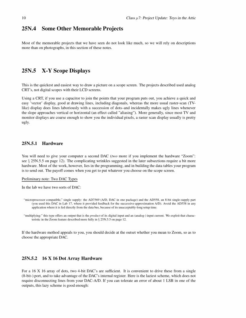
Figure 24: Inverted pendulum hardware: the guts of an old dot-matrix printer drive
The results have been mixed. One student whose computer control of this setup failed wrote a thorough and
somewhat formula-rich report concluding that he had failed because the motor’s response was too slow to
allow it to catch the falling stick.12 He proposed that the job could not be done till we got a heftier motor.
A term or so later, two students came closer to success, using purely analog methods.13 These students were
sophisticated enough to be well aware of the inherent stability problems, and tried summing various sorts of
error signal, making a PID loop that resembled the one you built in Lab 10. Their circuit worked well enoughso that we asked them to show it off to the new crop of students on opening day. In September, they pulled
out the machine that had worked in May—and were unable to get it to work again. This is a sad tale. Is it an
argument against analog circuits trimmed with multiple potentiometers, in favor of digital?
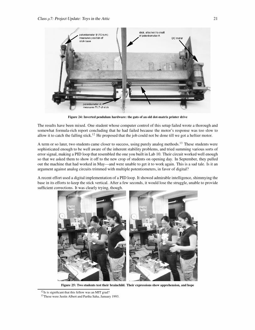
A recent effort used a digital implementation of a PID loop. It showed admirable intelligence, shimmying the
base in its efforts to keep the stick vertical. After a few seconds, it would lose the struggle, unable to provide
sufficient corrections. It was clearly trying, though.
Figure 25: Two students test their brainchild. Their expressions show apprehension, and hope
12Is is significant that this fellow was an MIT grad?13These were Justin Albert and Partha Saha, January 1993.
22 Class µ7: Project Update: Toys in the Attic
The tantalizing near success of the machine is visible in the photos of fig. 25 on the preceding page: first, with
anxiety and apprehension, the designers14 launch the thing; then they show their delight as the machine makes
its frantic small adjustments, keeping the ruler upright for several seconds. We omit the sadder conclusion,
in which the ruler falls.
25N.11 Games
25N.11.1 Pacman on scope screen
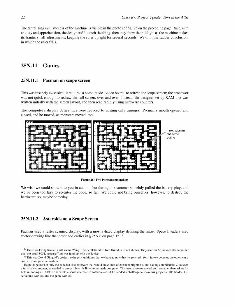
This was insanely excessive: it required a home-made “video board” to refresh the scope screen; the processor
was not quick enough to redraw the full screen, over and over. Instead, the designer set up RAM that waswritten initially with the screen layout, and then read rapidly using hardware counters.
The computer’s display duties thus were reduced to writing only changes: Pacman’s mouth opened andclosed, and he moved, as monsters moved, too.
Figure 26: Two Pacman screenshots
We wish we could show it to you in action—but during one summer somebdy pulled the battery plug, and
we’ve been too lazy to re-enter the code, so far. We could not bring ourselves, however, to destroy the
hardware; so, maybe someday. . . .
25N.11.2 Asteroids on a Scope Screen
Pacman used a raster scanned display, with a mostly-fixed display defining the maze. Space Invaders used
vector drawing like that described earlier in § 25N.6 on page 15.15
14These are Emily Russell and Lusann Wang. Their collaborator, Tom Dimiduk, is not shown. They used an Arduino controller ratherthan the usual 8051, because Tom was familiar with the device.
15This was David Gingold’s project, so hugely ambitious that we have to note that he got credit for it in two courses; the other was acourse in computer animation.
He put together not only the code but also hardware that would draw lines of constant brightness, and having compiled the C code ona full-scale computer, he needed to pump it into his little home-made computer. This need arose on a weekend, so rather than ask us forhelp in finding a UART IC he wrote a serial interface in software—as if he needed a challenge to make his project a little harder. His
serial link worked, and the game worked.

Class µ7: Project Update: Toys in the Attic 23
Figure 27: Asteroids on a scope screen
The game included the gravitational field of the “real” asteroids game. It was a marvel to watch (and this is
another of those pieces of hardware that we keep around, unable to stand tearing it apart).
25N.11.3 Other Great Games
Other wonderful games have appeared, but we lack photos of these; we’ll have to settle for words.
Stephane’s virtual-bubble game Stephane figured out how to decode the signals from a Nintendo Power-
Glove—a neat toy that can detect position and orientation of a glove, and also finger closings.16 He
used these signals to let his computer implement a game. The computer would issue beeps at a rate that
increased as the glove came nearer to the 3-D coordinates of a “virtual-object”—just some arbitrary
X,Y,Z point in the air. When the glove was at the target point, one could close the hand and then move
the target point, depositing it wherever one opened the hand. Dazzling!
Nomeer & Clay’s punch-out interface These students replaced the keypad of a Nintendo boxing game withan array of photosensors set in a square that looks like an empty picture frame.17 Behind the frame
they put a TV set showing the boxers. To punch the adversary the user punches air in the picture frame.
The nine segments of the frame defined functions earlier assigned to keys on the keypad: uppercut,
body-blow, etc. It was not a complicated project—but fun.
LED maze game Computer handled scope display, but the patterns displayed were stored as state machines
in PALs. So, one could change the maze (a set of rooms: rectangles with passages to other rectangles)
by swapping PALs. (Meredith Trauner & Robby Klein)
Tetris on an LED array (Kurt Shelton, 2009): 8051 running from flash. An awful lot of coding—but it did
work.
25N.12 Devices, Gadgets
25N.12.1 Mechanical: motors, etc.
25N.12.1.1 DC Motors
1. ...with tach A DC generator on the shaft gives rotation-rate feedback
...with slotted disc Optical sensor gives a few tens of pulse outputs per revolution of motor shaft: gives
rotation-rate feedback, or relative position feedback. (Taken from printer mechanism.)
2. ...with pot on shaft You could use the one-turn pot-on-shaft you used in the PID lab.
16Stephane Ryder, later a T.A. in our course.17Noah Helman, Sameer Bhalotra (both later TA’s for us) and Clay *.

24 Class µ7: Project Update: Toys in the Attic
25N.12.1.2 Stepper Motors
1. big, fine-resolution We have a lot of 200-steps-per-revolution motors. They need quite a lot of current(≈ 1 amp at 5V to 10V), sunk through power transistors, as described in § 29 on page 28.
2. small, coarse resolution We have fewer small motors; these show only perhaps 10 steps/revolution.
3. We have one really tiny model—less than a cm in diameter
25N.12.1.3 “Servo” Motors
1. radio-control model type These are sold as actuators for use in RC models. They rotate through about
270◦, holding a rotation position that is determined by the width (duration) of a logic pulse sent to the
motor repeatedly. They are quite small, use little power and provide substantial torque (the small motoris geared way down).
Applications: useful to steer a car, e.g.; but strong enough for, say, positioning a small robotic arm.
25N.12.1.4 Muscle Wires
1. muscle wires: tiny pullers
Yes, one manufacturer, at least, really calls them “muscle wires.” They shorten with considerable force
when heated, if they’ve been stretched while in their cool, soft state. They can contract by about 5% of
their length.
They call for very large currents, since the current’s job is to heat the wire with I2R power; but thepower needn’t be applied for long, if a brief contraction is required. So, a small battery can do the job,
keeping the whole setup small.
2. Applications: tiny robots
A couple of students made a 6-legged bug using muscle-wire—and concluded that they would never
touch muscle wire again: it gobbles current, doesn’t pull very hard, and is pesky to build with (requiring
tensioning adjustments).
Still, you can’t find a smaller, lighter actuator.
25N.12.2 Transducers
25N.12.2.1 Sound
1. ultrasonic send, receive “speaker”/microphone These are small diaphragms tied to a piece of piezo-
electric stuff, and are resonant at about 40kHz. Transmitter and receiver are either identical or very
similar to one another. Applications: ranging (send a burst; listen for echo); communication (send data
as sequence of bursts).
2. integrated ultrasonic transducer & amp
This was the method Polaroid used in its cameras. It is mimicked in SparkFun’s ranger.
The circuit (a little circuit board including a custom IC) does some neat tricks for us: generates thehigh-voltage drive for the transmitter; sends a “chirp” of several different frequencies, because some
materials reflect one frequency better than another; gradually cranks up the gain of the receive amplifier,
so as to take account of the attenuation of the reflected signal with distance (large if time is large).
Range is said to be 6 inches to 33 feet. Resolution is very good (1%).

Class µ7: Project Update: Toys in the Attic 25
25N.12.2.2 Infrared
1. IR remote-to-logic signal translator
This was described in Class micro 5 notes. The translator converts each the 40kHz burst put out by a
typical IR remote into a single logic level. (In the example shown in Class µ5 notes, a burst producesa logic Low; silence produces High.)
Applications: a circuit with brains (your computer) can translate the serial stream of logic levels that
an IR remote provides. A properly-synchronized 8-bit shift-register, done with computer or with hard-ware, could give you 256 options, in principle.
2. passive differential IR motion detector We have this in two forms:
(a) conventional detector: output is a logic level or the closing/opening of a switch.
(b) just the guts of passive motion detectors: when focused IR from a warm body moves across the
detector pair, a differential output appears.
25N.12.2.3 Color Discriminator
An IC array of detectors, each with a color filter. Two ingenious people paired this device with optical
fibers in an effort to read resistor color codes. The resistor colors were badly-defined and defeated them—
but the machine was able to read the colors of a ribbon cable, much of the time. Pretty good. We’ll be
pleased if you can improve on their machine, so as to automate resistor sorting!18 For specifications, see
www.parallax.com/detail.asp?product id=30054 (part is TAOS TCS230AMLN).
25N.12.2.4 Acceleration; Rotation Rate
25N.12.2.5 Accelerometers
Many are offered by re-sellers Parallax and Sparkfun. You should check their sites for new models even
niftier than the ones we have noticed. These companies typically offer what they call a “breakout board,” a
small printed-circuit that holds the tiny surface-mount part and sometimes a few passive parts such as pullups
or RC filters. You want this rather than the bare part.
You probably want a range of just a few g.19 With two axes, you can sense tilt. [ADD IMAGE]
Sparkfun offers a helpful discussion, on their site, of many alternative accelerometers.20
• analog output, 3-axis (±3g, 3V supply): ADXL335 Sometimes analog output is nice, letting you see,on a scope screen, a live image of the device outputs. The controller’s ADC can read these values—but
to read three axes with a single ADC requires use of an analog multiplexer. The SiLabs ’410 includes
such a multiplexer, allowing the single ADC to read all three axes in succession.
• digital output: SPI or I-squared-C: ADXL 345 (selectable range, ±2 to 16g, 3V supply). SPI interfaceis not hard to handle, especially with SiLabs hardware implementation of SPI (see Lab µ 5). The
accelerometer outputs are not viewable on a scope screen, but their values can be displayed on a laptop’s
screen through the SiLabs IDE. And taking the inputs in digital form is tidier and easier than what’s
required if the accelerometer speaks analog. SPI obviates need for successive ADC operations that
include swapping ADC input pins.
18Before you do this hard work, should we remind you that there is an easier way to determine the value of a resistor? Probably not.19One g, as you know, is acceleration due to gravity, here on the surface of earth.20Sparkfun’s “Accelerometer Buying Guide,” http://www.sparkfun.com/tutorials/167.

26 Class µ7: Project Update: Toys in the Attic
25N.12.2.6 Gyro
A small solid-state gyro gives an analog output proportional to angular acceleration. Here, one axis may be
enough, and analog output is more common than digital.
• 1 axis, analog output (3V supply): LY530AL
• 1 axis, both analog and SPI output (5V supply): MLX90609 - 300 (expensive! $60 in 2011).
25N.12.2.7 . . . Accel and Gyro combined
You can get accel and gyro on one board, to make things more compact. For example, IDG500/ADXL335(Sparkfun).
Surely lots of neat improved models will be coming along, so treat our list of devices as only a snapshot ofwhat was available back in 2013.
25N.12.2.8 Magnetic Field
We have two: plain and fancy:
1. Plain: Just Hall-effect sensors.
2. Fancy: a digital compassA circuit board that uses two orthogonal coils to sense variations in the orientation of the earth’s mag-
netic field relative to each of the two coils. An onboard microcontroller converts this information to an
easily-read serial output.
25N.12.2.9 Force
Small flexible sheets that put out a small voltage when flexed.
For specifications, see www.parallax.com/detail.asp?product id=30056.
25N.12.2.10 Speech
Speech Generation We have a board that takes ASCII characters in serial form (UART) and does its best
to pronounce the text phonetically.
Speech Recognition This is a very hard task—rendered utterly easy, by someone’s IC & little printed-
circuit board: the Sensory “Voice Direct” Speech Recognition Kit. One “trains” this board to recognize upto 15 words or phrases. When it recognizes one of these, it pulses one of its 15 output pins with a logic high
(duration about 1 second). You make whatever use you like, out of this feat of recognition. No one has yet
tried it.
Just getting it to work is nowhere near a ‘project.’ The challenge is to think up an interesting application. The
thing is small (3” X 3”), so it could, in principle, be mounted on a little vehicle (controlled by a microcon-
troller, probably—but not necessarily), permitting control of the vehicle by voice.
Class µ7: Project Update: Toys in the Attic 27
25N.12.3 Displays
1. liquid crystal (LCD) Most are 16-characters by 2 lines. One is back-lit. These look like a single I/Olocation; the computer feeds the display successive ASCII codes (7 or 8 bits), and the display takes
care of placing the characters properly.
Applications: talkative output for many sorts of gadget. (These may not be very exciting, since they
only carry our little computer a little way toward the very-talkative LCD’s that you’re accustomed to
on big computers.)
2. fluorescent multi-character display
3. Very similar to the LCD, but prettier and of course brighter.
4. “intelligent” LED display: 2-character or 4-character alphanumeric These are small. Each character
occupies a single I/O address, and wants to be fed ASCII.
Good for small, brief, bright verbal output.
5. bar-graph• LED:
An array of LEDs. You’ve seen similar displays used as VU meters on tape decks.• electrostatic: “E-Ink”
The appeal of E-Ink displays is zero-power consumption after a level is written. The difficulty is
their peculiar drive requirements: a brief pulse a ± 15 volts to turn a segement On or Off. But you
might enjoy showing off your skill, in making your own driver. The company takes the annoy-
ing line that their parts drive demands are confidential (they ask a user to sign a non-disclosure
agreement!). It’s no secret, though, and drive for a few segments is not hard to implement.
25N.12.4 Interface Devices
25N.12.4.1 Output
• solid-state relay These will turn On/Off a heavy AC load (motor, lamp, appliance) using a logic-level
as input. We have a giant and a midget version.
25N.12.4.2 In & Out
1. Radio serial link
A simple radio link could carry digital data: the simplest scheme would be to turn a transmitter ON,
then OFF, then ON.... The simplest transmitting device would be a fast logic-level oscillator gated ONor OFF (you could use a MOSFET to apply power or not). The simplest receiver would be an amplifier
driving an ’envelope detector’—a simple 1-diode AM detector like the one you met in Lab 3. You
mighty build the amplifier from scratch; or we may have an IC version available to you. A comparator
could then determine whether the envelope-detector showed that a burst of signal was coming in (“1”)
or not (“O”).
At its simplest, this burst/no-signal waveform could generate the logic-level pulse that controls the
position of a servo motor (see above), steering a little car, say. If you were more ambitious, you could
use this simple radio link to send serial data in one of the standard conventions—using conventionalRS-232 (to a UART on the receiving end) or perhaps I2C , mentioned just above.
The easier way to proceed is to buy ready-made Send and Receive modules. See, for example, Spark-
Fun’s many “RF link” boards, some simple, others integrating UART serial I/O.

28 Class µ7: Project Update: Toys in the Attic
25N.13 Stepper Motor Drive
25N.13.1 Generally
A stepper motor contains two coils surrounding a permanent-magnet rotor; the rotor looks like a gear, and its
’teeth’ like to line up with one or the other of the slightly-offset coils, depending on how the current flows in
the coils. A DC current through these coils holds the rotor fixed. A reversal of current in either coil moves
the rotor one ‘step’ clockwise or counter-clockwise (a coarse stepper may move tens of degrees in a step; amoderately fine stepper may move 1.875 degrees: 200 steps/revolution). The sequence in which the currents
are reversed (a gray code) determines the direction of rotation.
For example:
Figure 28: Sample waveforms to drive stepper motor’s two coils
25N.13.1.1 Integrated Stepper Driver
Integrated stepper-motor driver chips can make driving a stepper extremely easy: the chip usually is just
a bidirectional counter/shift-register, capable of sinking and sourcing more current than an ordinary logic
gate. Fancier IC’s, like the Allegro A3967SLB21 can provide finer control: so-called “microstepping.” The
A3967SLB permits one-eighth steps. This part also includes driver transistors capable of more than onewould expect in a modest 20-pin DIP: 750mA at up to 30V. This is not enough for a large stepper motor, but
is impressive, indeed.
Such drivers reduce the controller’s job to determining direction of rotation and rate of stepping (an edge on
the IC pin initiates a single step).
25N.13.1.2 The controller can drive the stepper
If you don’t want to be so fancy, and so lazy, you can use a few pins of the controller to drive power transistors
wired to the motor. Power MOSFETs will do the job: the IRLZ34 used in Lab 12 (55V, 30A max) could do
the job easily.
Here is the scheme:
Figure 29: Stepper driver hardware
One way to generate such successive patterns is to load a value into a register and rotate that value, feeding
two adjacent bits to the motor’s two coil-drivers:
21This surface mount part is available in a handy breakout board from Sparkfun: ROB-10267, “Easy Driver. . . .”

Class µ7: Project Update: Toys in the Attic 29
Figure 30: Rotated register can produce the 2-bit drive pattern for stepper
25N.13.2 Using the stepper motor
You will dream up your own ways to use a motor, but here are a few uses students have tried.
Crane
Two motors, each with a spool on its shaft to wind cord, can rest on a tabletop, with the load suspended fromboth cords. The two motors can work together to lift, move, then lower the load. This is easy to do crudely,
but would be challenging if one wanted to let the load move vertically, then horizontally, then vertically again.
A small electromagnet could let the machine pick up and drop an iron load (a washer, perhaps). (A small
spool of wire-wrap wire is handy for an instant home-made coil; put an iron bolt through its core). (One
student built such an electromagnet, hung it from a stepper-driven ‘winch,’ and mounted the whole thing onthe tractor described below.22)
Drawing machine
Two motors can drive the X and Y knobs of a child’s sketching toy (the kind with a glass cover, coated with
aluminum dust on its sealed underside; a sharp stylus etches a dark trace in this material). This machine wasdescribed in Class notes µ 5.
Such a machine makes a curious form of semi-permanent drawing. The scheme resembles ‘turtle graphics’:any new vector begins where the last one terminated. This application requires motors of exceptionally high
torque, and a little machine-shop skill in order to link the motors to the two shafts.
Figure 31: two stepper motors can drive an X-Y drawing toy
22This was Dylan Jones’ ingenious work. (1987)

30 Class µ7: Project Update: Toys in the Attic
25N.14 Project Ideas
25N.14.1 Nifty Recent Projects, for your inspiration
25N.14.2 New & Untested
25N.14.2.1 Speech Recognition
You certainly don’t want to try it the conventional, full-scale way: transforming to the frequency domain and
then comparing against Lab µ7: Project Update: Toys in the Attics. (But see the cheap trick suggested above
under 1.6: use someone’s IC that does the hard work for you.) We want a rough-and-ready method.
One strategy—used, for example, on an old Radio Shack chip that could distinguish “Stop” from “Go” for
toys—is to look at just zero-crossings—in other words, find the dominant frequency (this method mightdetect the “Sssss” in “Stop”). Count zero-crossings in hardware or software, and check against a few range
definitions: ‘≥ 5kHz =⇒ Sssss,’ and so on.
A little more refined: use a pair of steep filters, high-pass, low-pass, with little overlap; then compare ampli-
tudes (time-averaged, we suppose) above and below this frequency boundary. Bell Labs experimented with
this method in the early ’50’s, placing the boundary around 900Hz, and found they could distinguish the 10
digits pretty well.
25N.14.2.2 Audio Encryption
Here’s an idea we saw proposed in a trade magazine: simple encryption of audio—say, for a cordless phone—by inverting the frequency spectrum of the speech.
Do this by exploiting a violation of Nyquist’s rule: multiply the speech data (in digital form) by a large squarewave at a frequency just slightly above the top signal frequency. The result is an inverted frequency spectrum
(because of “aliasing” or “folding”).
De-crypt by multiplying by the same frequency. The “multiplication” is simpler than it sounds: just flip the
MSB of the data, at the multiplication rate (apply a 1, then a zero, then a 1... to an XOR with the MSB of
data).
25N.14.2.3 Music effects: chorus, etc.?
You may dimly recall a phase-shifter, back in the second op amp lab, that could vary phase by varying a
resistance to ground.23 If you use a digipot like the one you met in Lab µ5 you can make a computer-controlled phase shifter.
An alternative way to get the same result might use a multiplying DAC—which can be described as a digitally-controlled attenuator; output is the product of the analog and digital inputs.
Combined with a summing circuit, in principle either shifter can make interesting rock-&-roll sounds—likethose vaguely mentioned in Lab Op Amps 2. To hear a repertoire of such sounds, try http://www.harmony-
central.com/Effects This web page also includes circuits and helpful links.
23This was the second of two phase-shifter designs.

Class µ7: Project Update: Toys in the Attic 31
25N.15 Two Programs that Could be Useful: LCD, Keypad
25N.15.1 LCD driver; Keypad scanner
These hardware interfaces are describd in Class notes µ 5. The code to implement these is posted on our
course website, in case you want to use one of these devices in a project.
class notes projects july12.tex; April 29, 2013

Index
project
examplesetch-a-sketch, 7
game: asteroids on scope, 22
game: pacman on scope, 22
inverted pendulum, 19
laser character display, 5–6
sound source detector, 6spinning LED display, 16
vehicles, 17–19
X-Y table, 8
inverted pendulum, 22
projectshardware
displays, 27
motors, 23–24
muscle wire, 24
stepper motor drive, 27–30software
LCD drive, keypad scan, 31
transducers
accelerometer, 25
color discriminator, 25
force, 26gyro, 26
infrared, 25
magnetic field, 26
speech recognition, 26
ultrasonic, 24projects (general advice), 4
PSOC (Cypress), 3–4
32

Physics 123: Final Project Evaluation F rmo
Olympic Scoring
W try to judge projects the way people judge divers’ achievements: degree of difficulty timeseperfection of execution.
Whose: _______________________________________________________________________
Description: ___________________________________________________________________
Degree of difficulty (0..1) : ___ P rfection (%): ___eprelim. SCORE (= product): ____
…then we correct for hardship & suffering, and time invested:
Loneliness Multiplierbonus for working alone (hard to keep going without help,consultation or comfort) X1.1 __
…producing a preliminary product: ____
…then we correct for what amounts to time invested (time that might havebeen invested in reviewing):
T il & Suffering additionobonus for long hours in lab and persistence in the face ofdaunting difficulties + ____
…and thus we get a boosted total:
TOT L, after boost (0..1): _____A
X 5% (Max P ssible Boost for Project) = BOOST = ______o
(ProjEval.597; 5/12/100 10:37am)