civil 3d introduction · civil 3d introduction • points are data collected by surveyors which...
TRANSCRIPT
Civil 3D Introduction
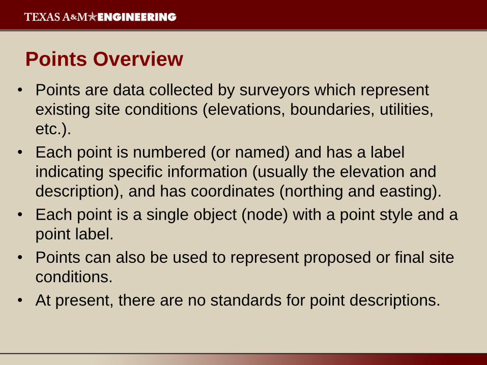
• Points are data collected by surveyors which represent
existing site conditions (elevations, boundaries, utilities,
etc.).
• Each point is numbered (or named) and has a label
indicating specific information (usually the elevation and
description), and has coordinates (northing and easting).
• Each point is a single object (node) with a point style and a
point label.
• Points can also be used to represent proposed or final site
conditions.
• At present, there are no standards for point descriptions.
Points Overview
Points Overview
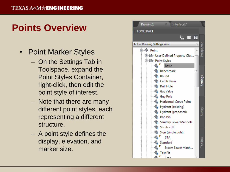
• Point Marker Styles
– On the Settings Tab in
Toolspace, expand the
Point Styles Container,
right-click, then edit the
point style of interest.
– Note that there are many
different point styles, each
representing a different
structure.
– A point style defines the
display, elevation, and
marker size.
Points Overview
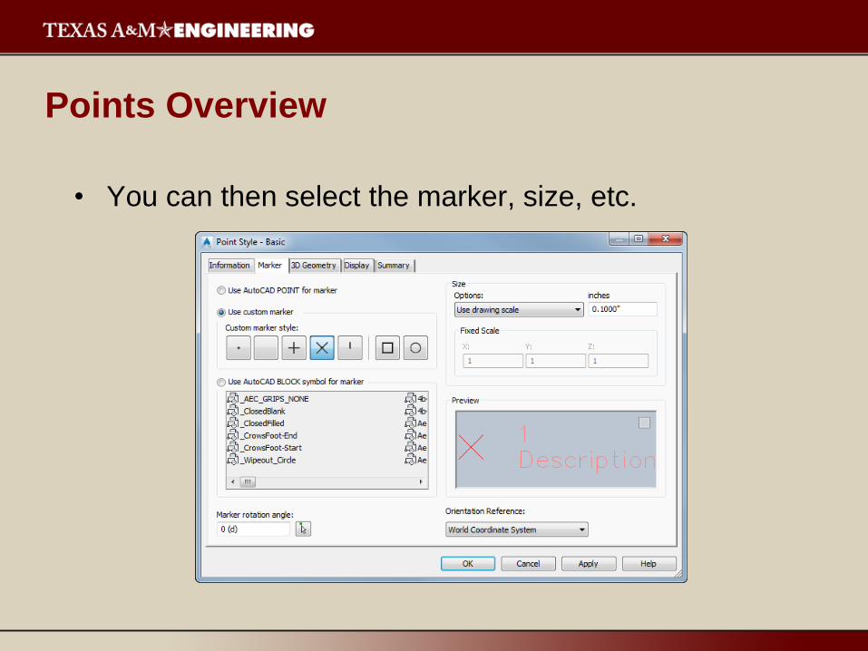
• You can then select the marker, size, etc.
Points Overview
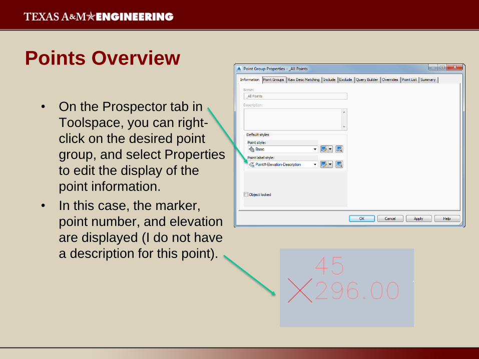
• On the Prospector tab in
Toolspace, you can right-
click on the desired point
group, and select Properties
to edit the display of the
point information.
• In this case, the marker,
point number, and elevation
are displayed (I do not have
a description for this point).

Points Overview
• You can also subdivide your
points into specific groups
for further display and
analysis (such as existing
ground, utilities, boundaries,
trees, etc.).
• Description keys and point
groups help to automate
point layers and allow you to
manage points with similar
purposes.

Creating Points
• A common way to bring elevation data into C3D is to import the
points from a data file.
• This data file must have the point number, northing, easting,
elevation, and description (if needed).
• These files can be comma or space delimited, and arranged in
various manners.
• As an example, if the file format is listed as PENZD, the first
number is the point number, the second number is the easting,
the third number is the northing, the fourth number is the
elevation, and the fifth number is the description.
• You must be informed of the format used (ENZ, NEZ, PENZ,
PNEZ, etc.).
Creating Points
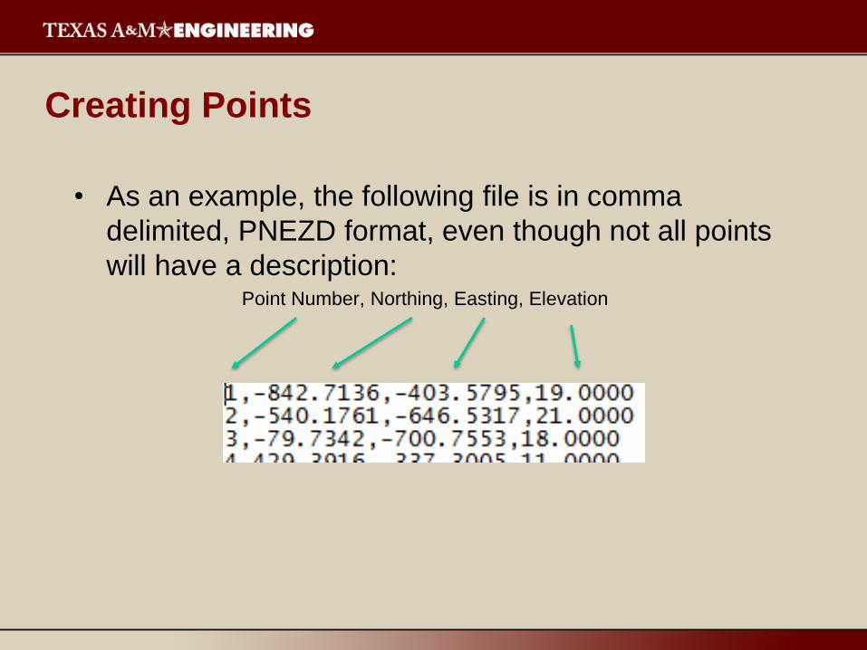
• As an example, the following file is in comma
delimited, PNEZD format, even though not all points
will have a description:Point Number, Northing, Easting, Elevation

Points Creation
Points Creation
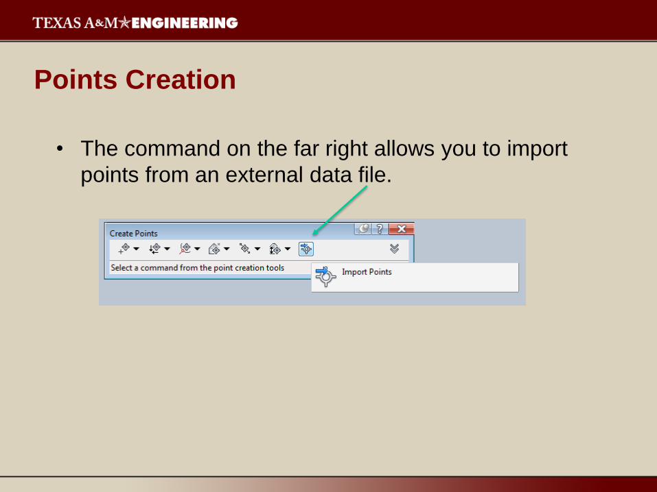
• The command on the far right allows you to import
points from an external data file.

Points Creation
• Click the “Plus” sign
to browse for you
point file:
• Scroll down to select
the proper file
format:
• Click on the box to
“Add Points to Point
Group”

Points Creation
• Then click on the
“Plus” sign and give
the point group a
unique name.
• Notice that the point
group name is now
populated in your
window.
• Click OK.
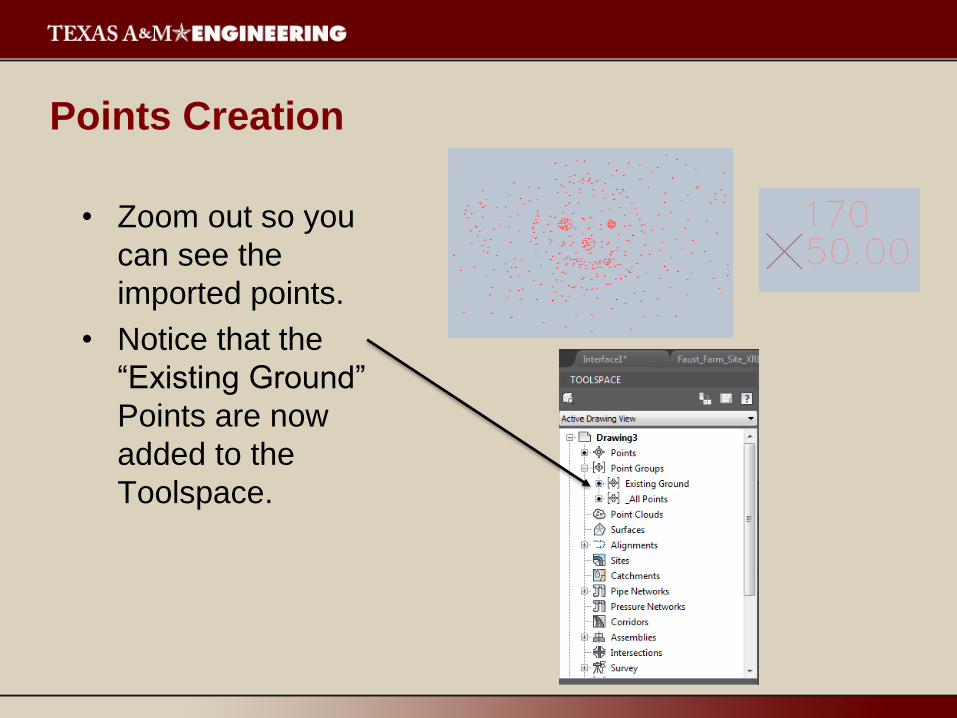
• Zoom out so you
can see the
imported points.
• Notice that the
“Existing Ground”
Points are now
added to the
Toolspace.
Points Creation
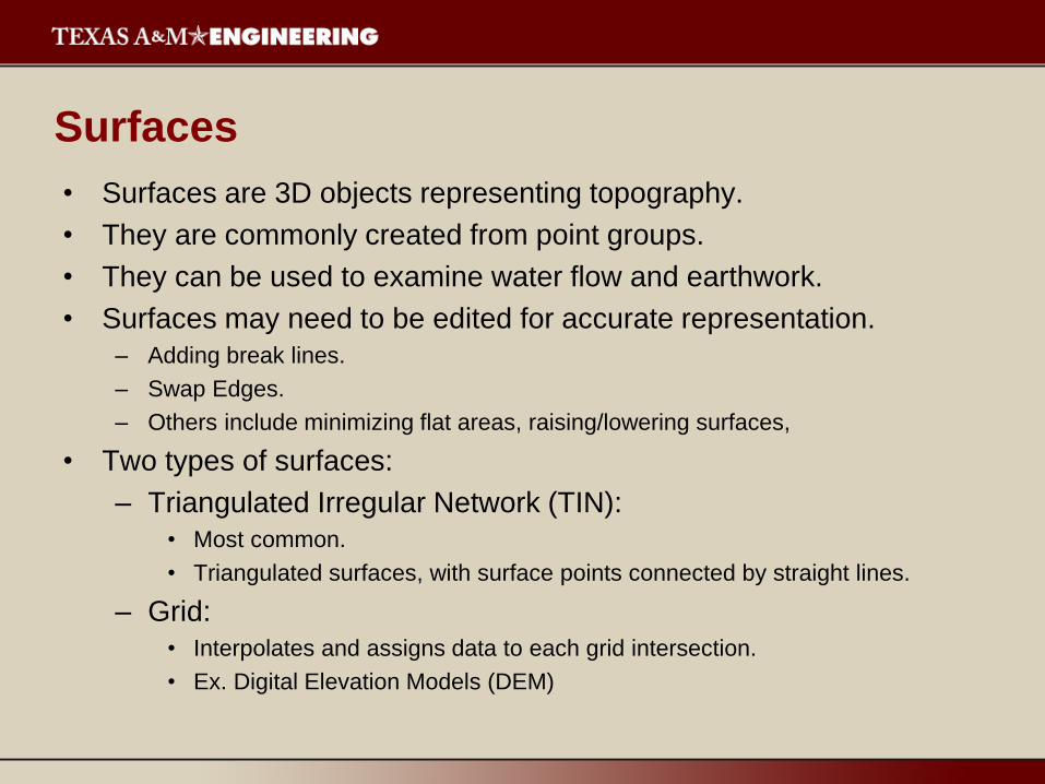
• Surfaces are 3D objects representing topography.
• They are commonly created from point groups.
• They can be used to examine water flow and earthwork.
• Surfaces may need to be edited for accurate representation.
– Adding break lines.
– Swap Edges.
– Others include minimizing flat areas, raising/lowering surfaces,
• Two types of surfaces:
– Triangulated Irregular Network (TIN):
• Most common.
• Triangulated surfaces, with surface points connected by straight lines.
– Grid:
• Interpolates and assigns data to each grid intersection.
• Ex. Digital Elevation Models (DEM)
Surfaces
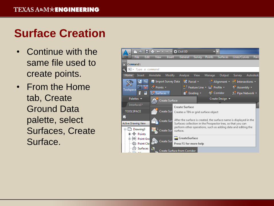
• Continue with the
same file used to
create points.
• From the Home
tab, Create
Ground Data
palette, select
Surfaces, Create
Surface.
Surface Creation
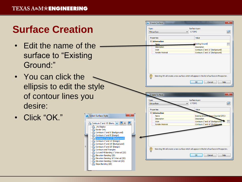
• Edit the name of the
surface to “Existing
Ground:”
• You can click the
ellipsis to edit the style
of contour lines you
desire:
• Click “OK.”
Surface Creation
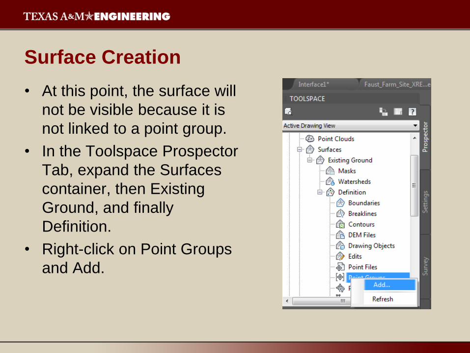
• At this point, the surface will
not be visible because it is
not linked to a point group.
• In the Toolspace Prospector
Tab, expand the Surfaces
container, then Existing
Ground, and finally
Definition.
• Right-click on Point Groups
and Add.
Surface Creation
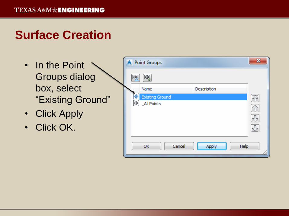
• In the Point
Groups dialog
box, select
“Existing Ground”
• Click Apply
• Click OK.
Surface Creation

• The surface
representing
the existing
ground will be
created and
should be
displayed.
Surface Creation
Surface Creation
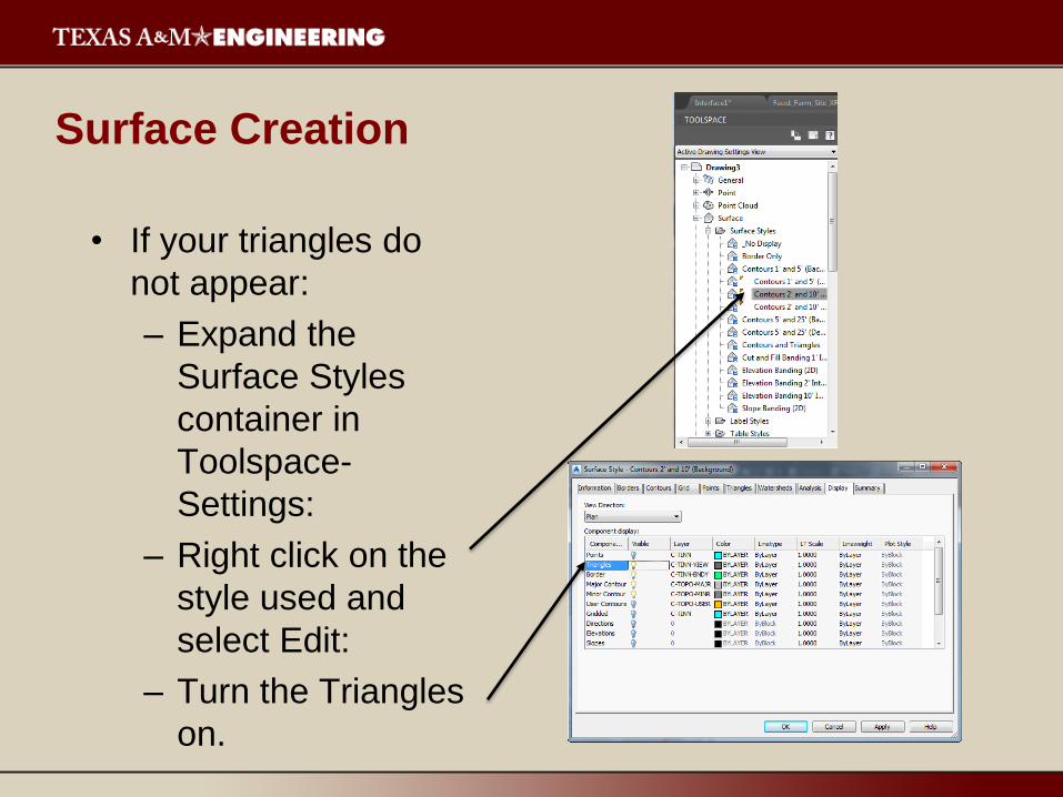
• If your triangles do
not appear:
– Expand the
Surface Styles
container in
Toolspace-
Settings:
– Right click on the
style used and
select Edit:
– Turn the Triangles
on.
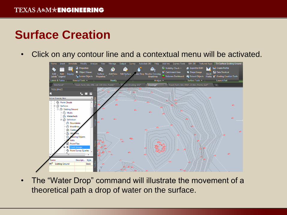
• Click on any contour line and a contextual menu will be activated.
• The “Water Drop” command will illustrate the movement of a
theoretical path a drop of water on the surface.
Surface Creation

• The path of the water
is represented by a
2D polyline.
Surface Creation
Alignments
• Alignments are used in most civil engineering
projects to assist with laying out:
– Roads, railways, runways, and bike trails.
– Swales, waterways, utilities, levees, dams, and landfills.
• Alignments are used to represent center lines, lane
boundaries, shoulders, right-of-ways, etc.
• Alignments are custom objects that are similar to
polylines.
– Can contain tangents (line segments), curves, and spirals.
Alignments
• Alignments, profiles, and cross sections provide for a
complete three-dimensional description of the road.
• When laying out a construction site, oftentimes
parcels, polylines, and arcs are used as base
geometry for interior roads.
– These objects are later converted into alignments.
Five Types of Alignments
• Centerline
– Most common.
– Used when the location and design parameters of the
centerline of the road are known.
• Offset
– Used to create transitions within a corridor design.
• Curb Return
– Used to base the road design from the curb.
– Used to connect edges of intersecting roadways.

Five Types of Alignments
• Rail
– Used to calculate
curves along chords
rather than arcs.
– Used to set track
width and calculate
cants.
• Miscellaneous
– Used when the
alignment you wish
to create does not
fall into any of the
other categories.
Five Types of Alignments
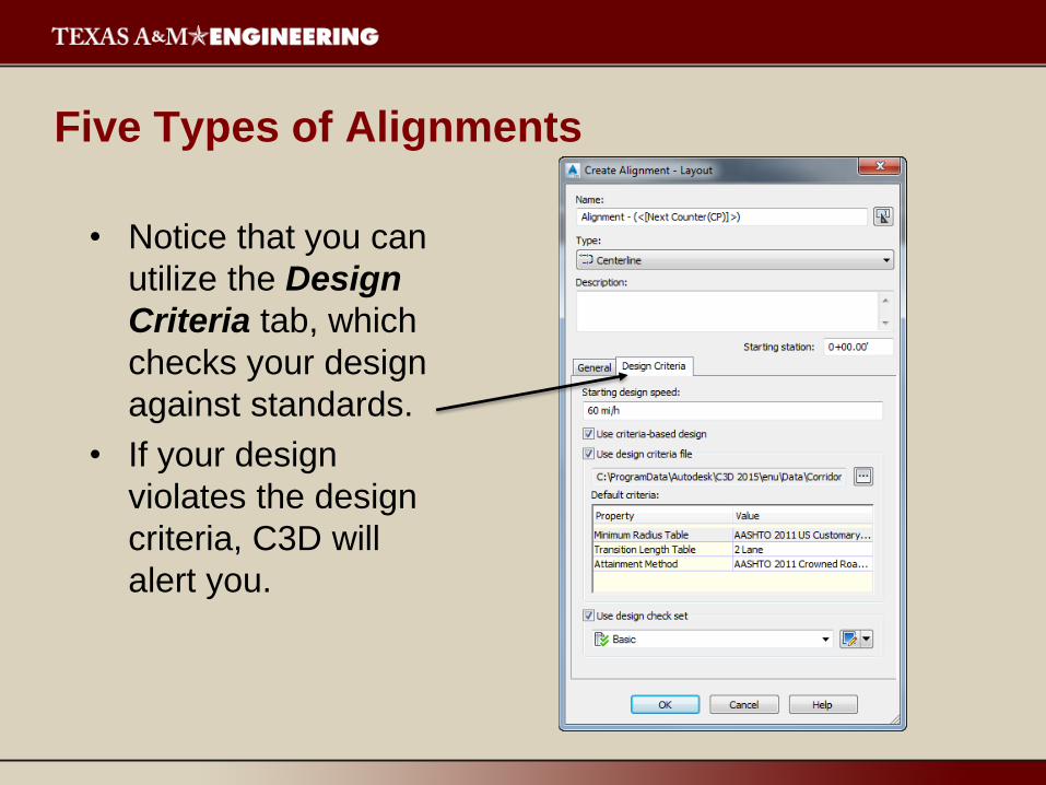
• Notice that you can
utilize the Design
Criteria tab, which
checks your design
against standards.
• If your design
violates the design
criteria, C3D will
alert you.
Creating Alignments in C3D
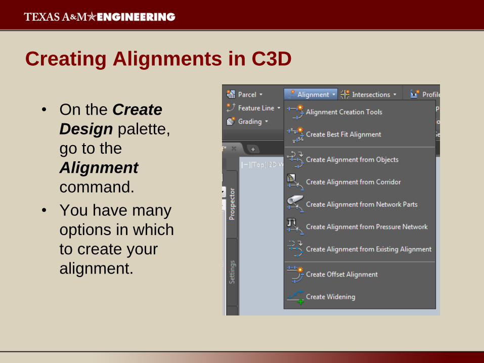
• On the Create
Design palette,
go to the
Alignment
command.
• You have many
options in which
to create your
alignment.
Creating Alignments in C3D
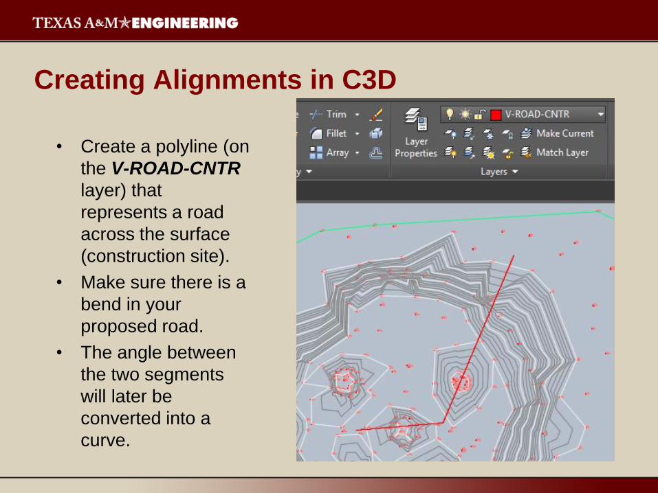
• Create a polyline (on
the V-ROAD-CNTR
layer) that
represents a road
across the surface
(construction site).
• Make sure there is a
bend in your
proposed road.
• The angle between
the two segments
will later be
converted into a
curve.
Creating Alignments in C3D
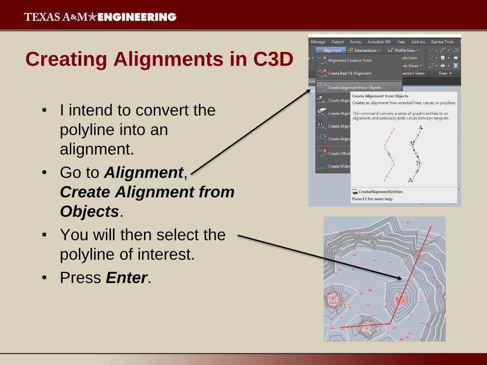
• I intend to convert the
polyline into an
alignment.
• Go to Alignment,
Create Alignment from
Objects.
• You will then select the
polyline of interest.
• Press Enter.
Creating Alignments in C3D
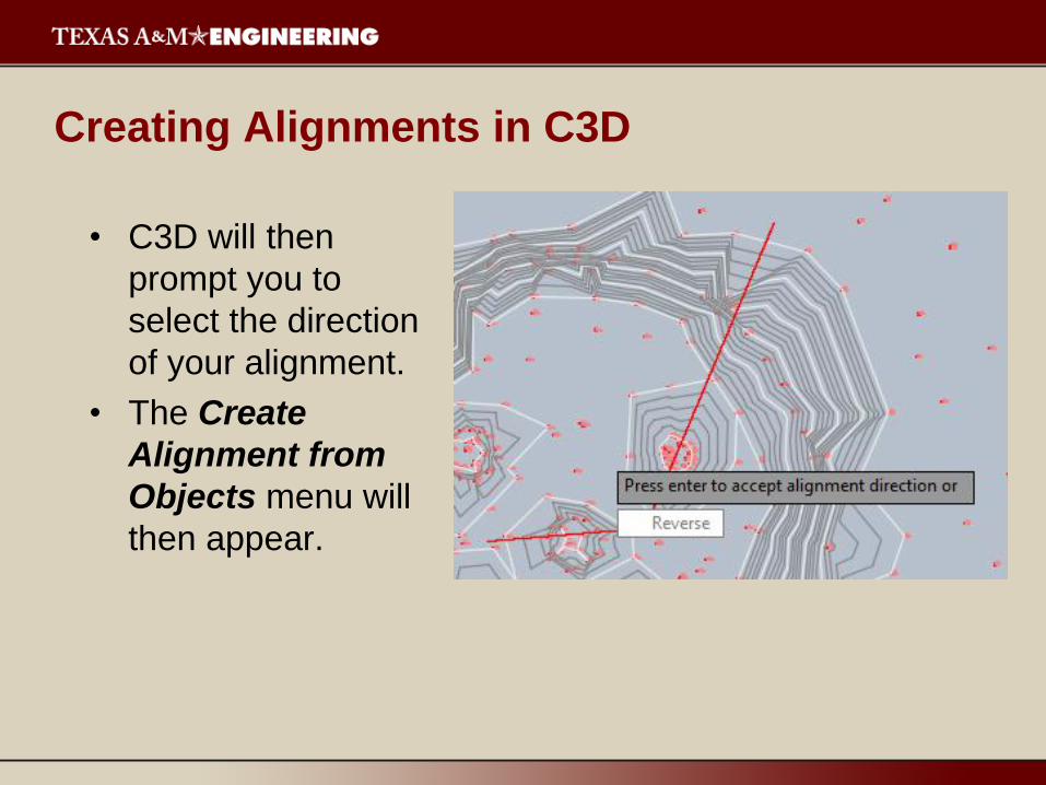
• C3D will then
prompt you to
select the direction
of your alignment.
• The Create
Alignment from
Objects menu will
then appear.
Creating Alignments in C3D
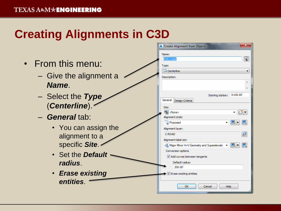
• From this menu:
– Give the alignment a
Name.
– Select the Type
(Centerline).
– General tab:
• You can assign the
alignment to a
specific Site.
• Set the Default
radius.
• Erase existing
entities.
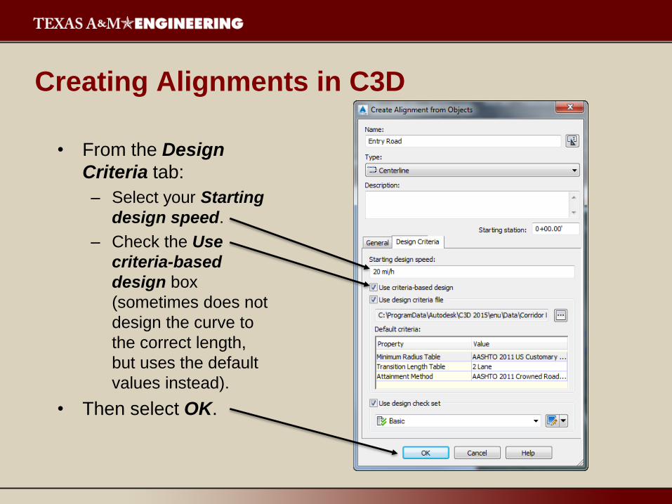
Creating Alignments in C3D
• From the Design
Criteria tab:
– Select your Starting
design speed.
– Check the Use
criteria-based
design box
(sometimes does not
design the curve to
the correct length,
but uses the default
values instead).
• Then select OK.
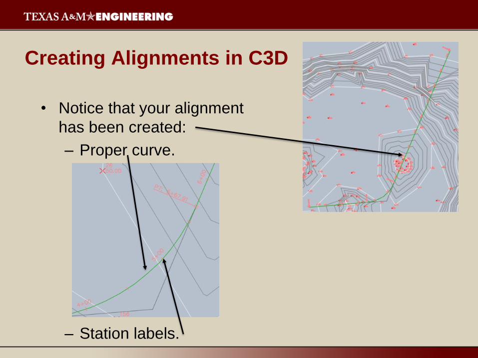
Creating Alignments in C3D
• Notice that your alignment
has been created:
– Proper curve.
– Station labels.
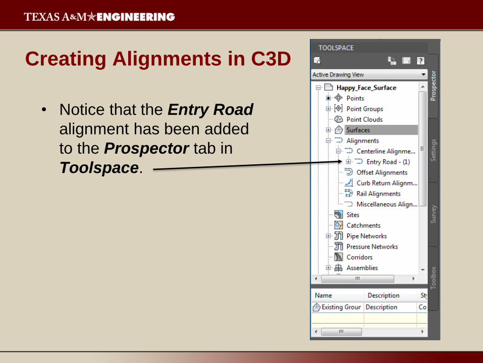
Creating Alignments in C3D
• Notice that the Entry Road
alignment has been added
to the Prospector tab in
Toolspace.

Alignment Hints
• Make sure polylines extend beyond other intersecting
polylines (or come to an exact “T”), as this process
will ensure that intersections are created properly.
• Make sure that at least one intersecting road does
not end at the intersection. Make sure it carries
through.
• While C3D will allow you to create multiple
alignments at once, creating them individually will
allow you to have more control over the design of
each alignment.

Profiles
• A profile is a side view of an alignment, with
elevations shown along the alignment length.
• A profile consists of a profile grid and its annotation.
• In C3D, they are dynamic, geometric objects that
update if either the alignment or surface is altered.
• The next step after creating the alignment is to
produce the profile view.
– This process is significantly easier, and more
intelligent, than doing it in AutoCAD.
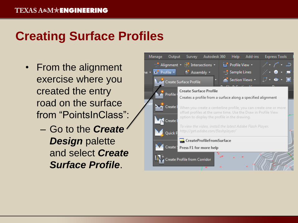
Creating Surface Profiles
• From the alignment
exercise where you
created the entry
road on the surface
from “PointsInClass”:
– Go to the Create
Design palette
and select Create
Surface Profile.
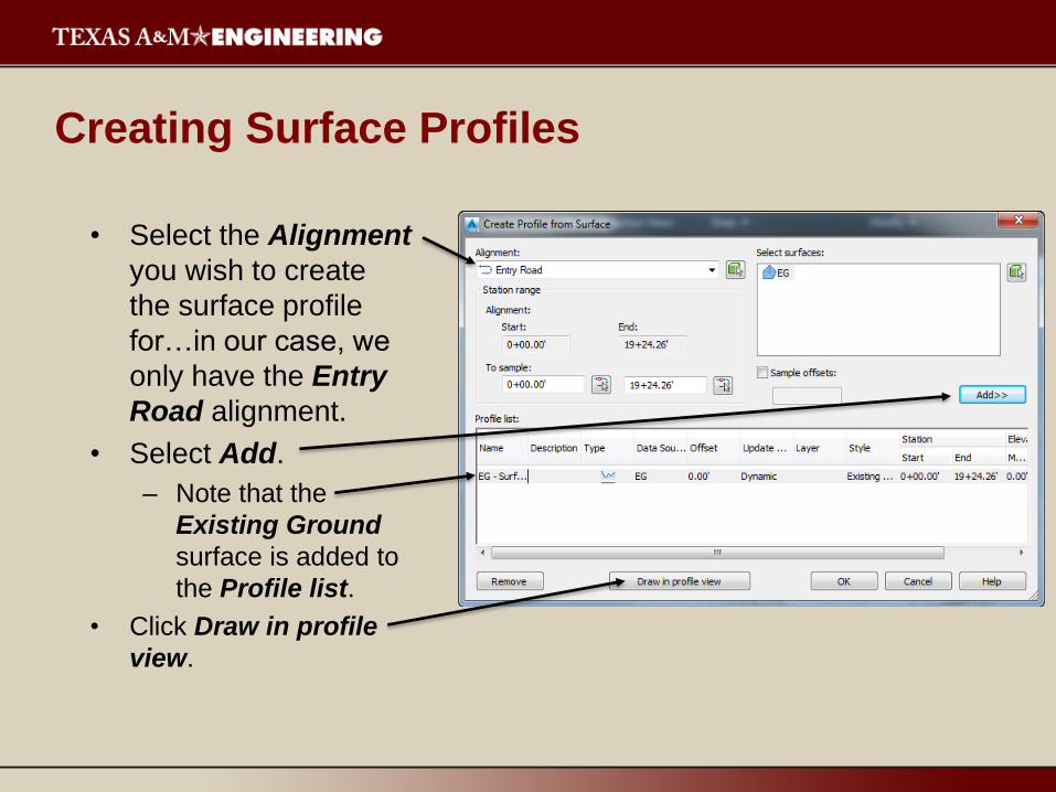
Creating Surface Profiles
• Select the Alignment
you wish to create
the surface profile
for…in our case, we
only have the Entry
Road alignment.
• Select Add.
– Note that the
Existing Ground
surface is added to
the Profile list.
• Click Draw in profile
view.
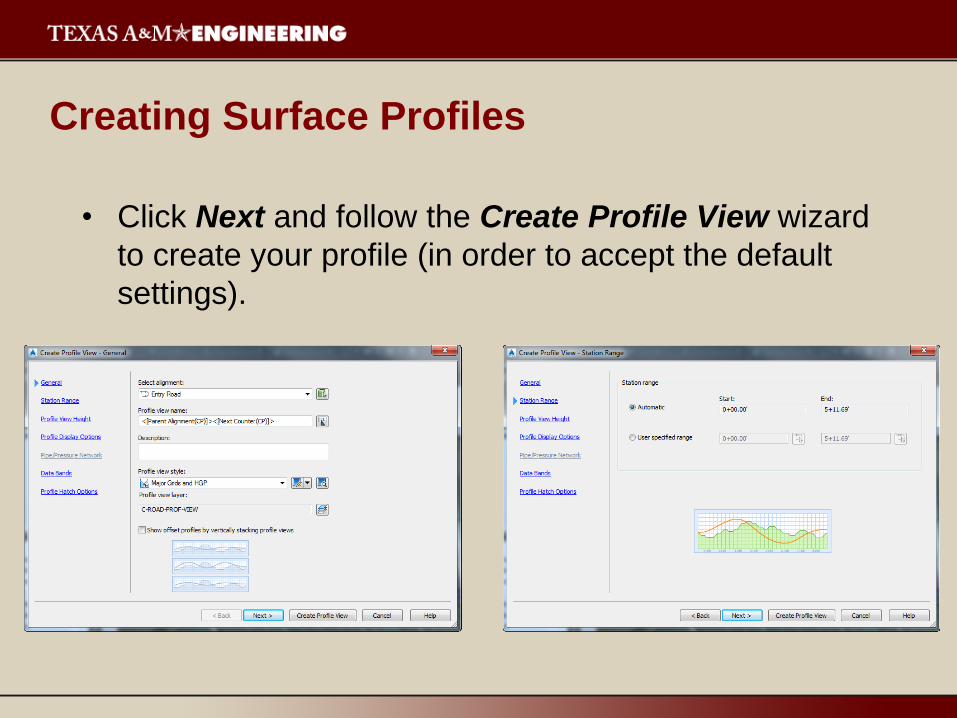
Creating Surface Profiles
• Click Next and follow the Create Profile View wizard
to create your profile (in order to accept the default
settings).

Creating Surface Profiles
Finally, select Create Profile View.
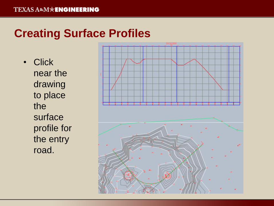
Creating Surface Profiles
• Click
near the
drawing
to place
the
surface
profile for
the entry
road.
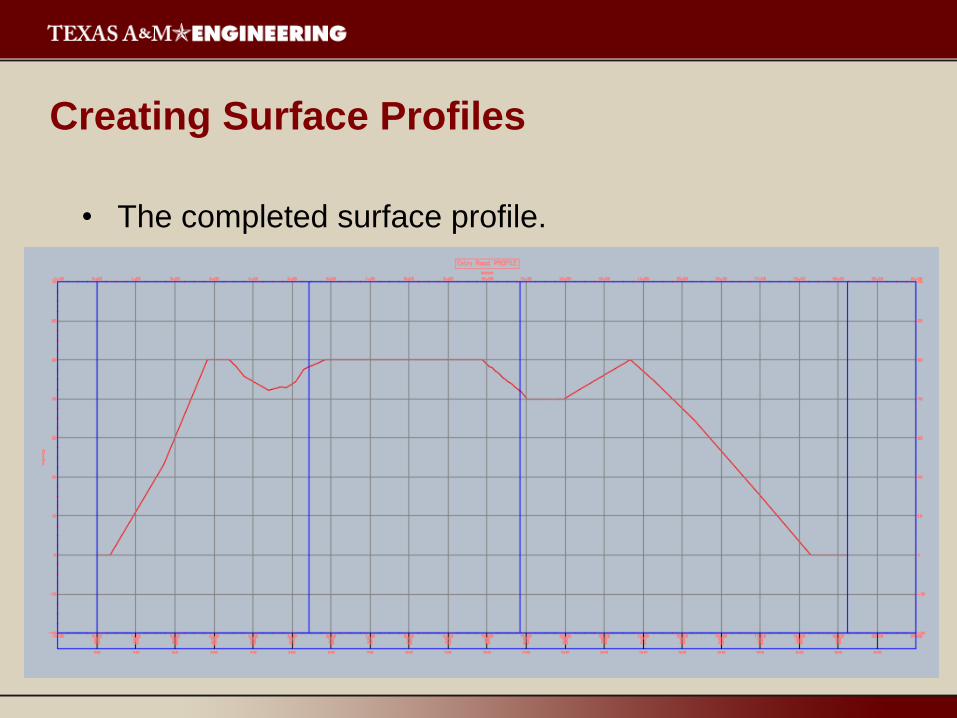
Creating Surface Profiles
• The completed surface profile.
Creating Design Profiles
• To this point, we have created profile views based on
a surface (Existing Ground).
• Now we will construct a design profile, since very
rarely will the road match up perfectly with the natural
topography.
• We will superimpose both profiles on the same
graph.
Creating Design Profiles
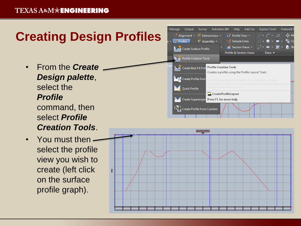
• From the Create
Design palette,
select the
Profile
command, then
select Profile
Creation Tools.
• You must then
select the profile
view you wish to
create (left click
on the surface
profile graph).
Creating Design Profiles
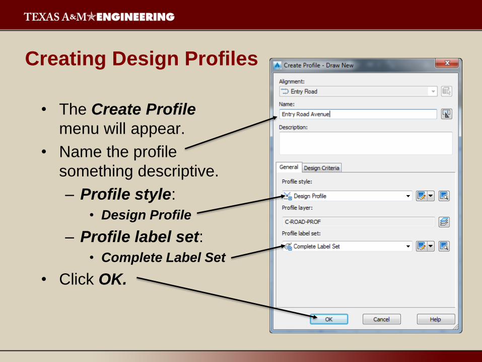
• The Create Profile
menu will appear.
• Name the profile
something descriptive.
– Profile style:
• Design Profile
– Profile label set:
• Complete Label Set
• Click OK.

Creating Design Profiles
• The Profile Layout Tools menu will appear.
• Select the Curve Settings option.
• The Vertical Curve Settings menu will appear (select defaults).
Then click OK.
-The K-Value is the horizontal
distance required to achieve a 1%
change in the slope of the vertical
curve.
-K-Values for various speeds are
provided in AASHTO Green Book
(A Policy on Geometric Design of
Highways and Streets).
-Crest Curves are curves that
convex upwards (ex. curves at hill
crests and when uphill grades
becomes less steep).
-Sag Curves are curves that
concave upwards (ex. curves at
valley bottoms and when uphill
grades become steeper).

Creating Design Profiles
• Then select Draw Tangents With Curves from the Profile
Layout Tools menu.
• Create the design profile by drawing on the surface profile
graph.

Creating Design Profiles
• When you are finished selecting points to create your
design profile, press Enter.
• Your design profile should now appear on your
surface profile graph.
• Close the Profile Layout Tools menu when you are
finished.

Creating Design Profiles
• Finished profile graph.
• Notice that the grade
and stations are
labeled.
Creating Design Profiles
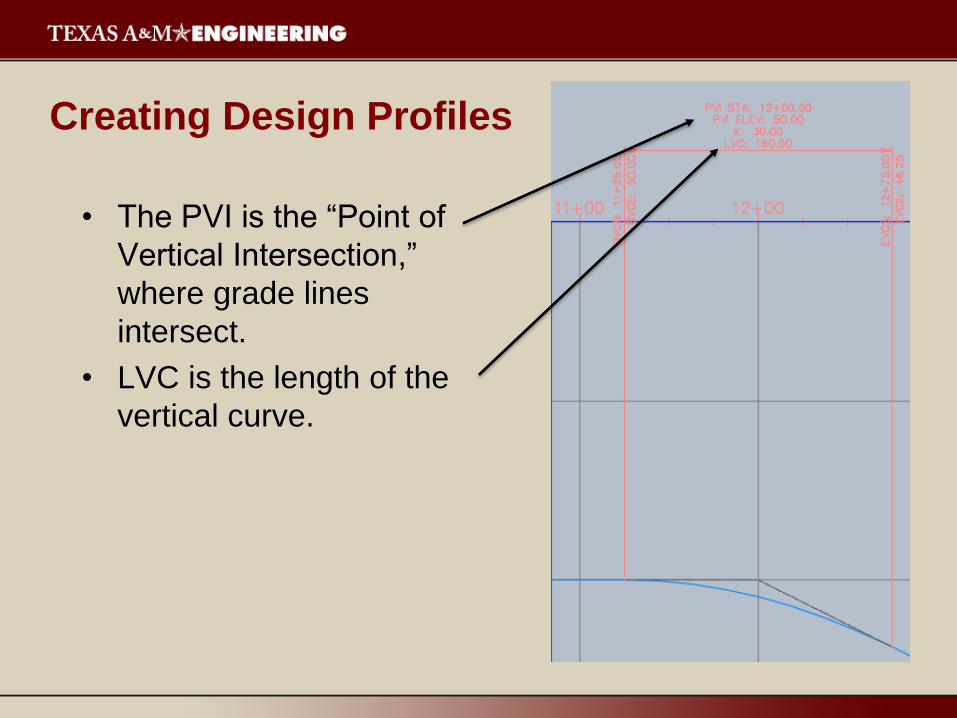
• The PVI is the “Point of
Vertical Intersection,”
where grade lines
intersect.
• LVC is the length of the
vertical curve.
Assemblies
• An assembly defines the attachment point of a
roadway cross-section to the horizontal and vertical
alignments.– Undivided Crowned Road
– Undivided Planar Road
– Divided Crowned Road
– Undivided Planar Road
– Railway
– Other
• Subassemblies represent individual components of
the proposed cross-section (such as a lane or curb).
Corridors
• A corridor is a 3D model of a proposed design based
on alignments, profiles, and assemblies.
• Corridors can be used to represent a single
alignment, profile, and assembly (such as a single
road) or can contain multiples of each.
• When modeling intersections, it is good practice to
have all intersecting roads as part of the same
corridor object.
Intersections
• Intersections are complex corridor models that
automatically create offset and curb return geometry
where two intersecting alignments meet.
• Geometry is automatically updated should the
alignment, profile, assembly, or surface is altered.
• Four intersection objects possible:– Create Intersection
– Create Roundabout
– Add Approach
– Add Turn Slip Lane
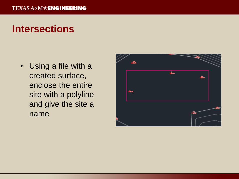
Intersections
• Using a file with a
created surface,
enclose the entire
site with a polyline
and give the site a
name

Intersections
• Create a parcel from
the polyline you just
created.
• Make sure you choose
the label style “Name
Square Foot & Acres,
Automatically add
segment labels, and
erase existing entities.

Intersections
• Create alignments for each of the proposed roads you
drew as polylines.
Intersections
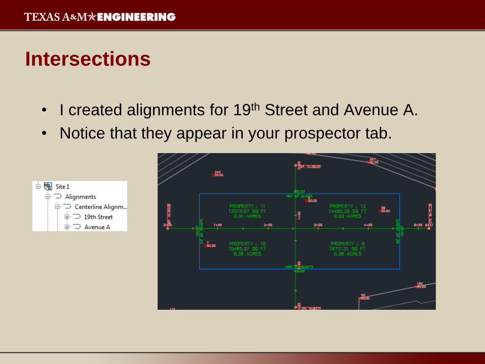
• I created alignments for 19th Street and Avenue A.
• Notice that they appear in your prospector tab.

Intersections
• Create Right of Way Parcels.
• Remember you have to
select the parcel label.
• Use the default values.

Intersections
• Now create
the surface
profile for
each
alignment.
Intersections
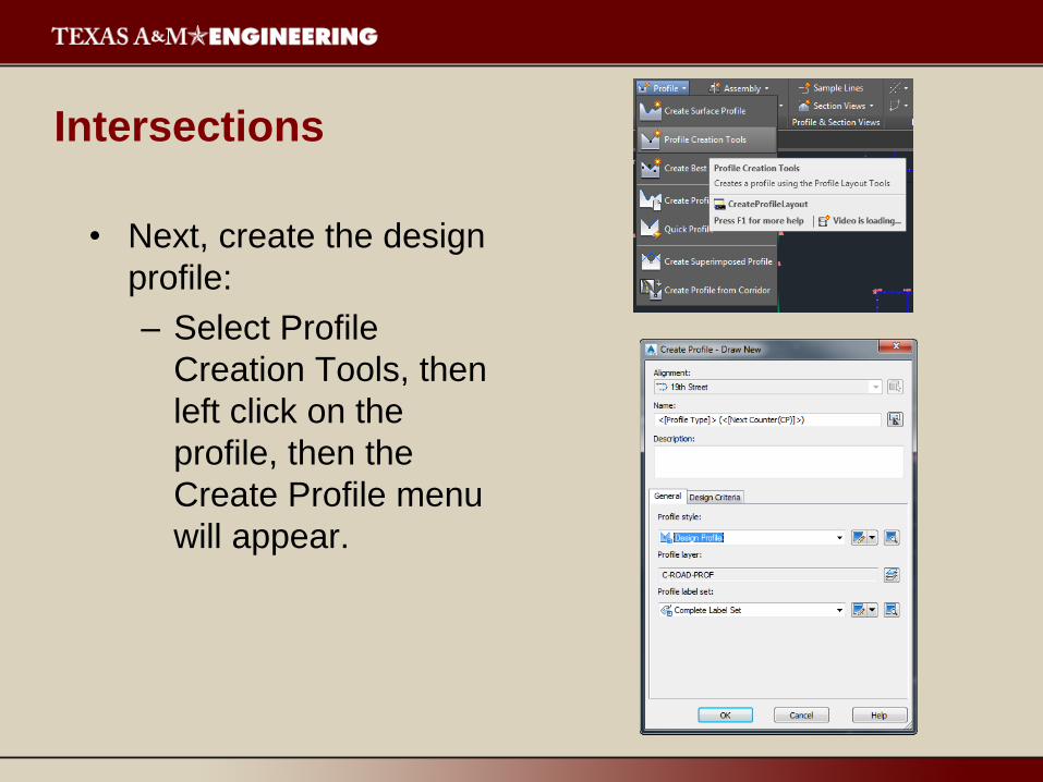
• Next, create the design
profile:
– Select Profile
Creation Tools, then
left click on the
profile, then the
Create Profile menu
will appear.
Intersections
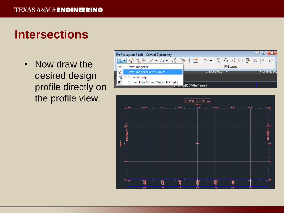
• Now draw the
desired design
profile directly on
the profile view.
Assemblies
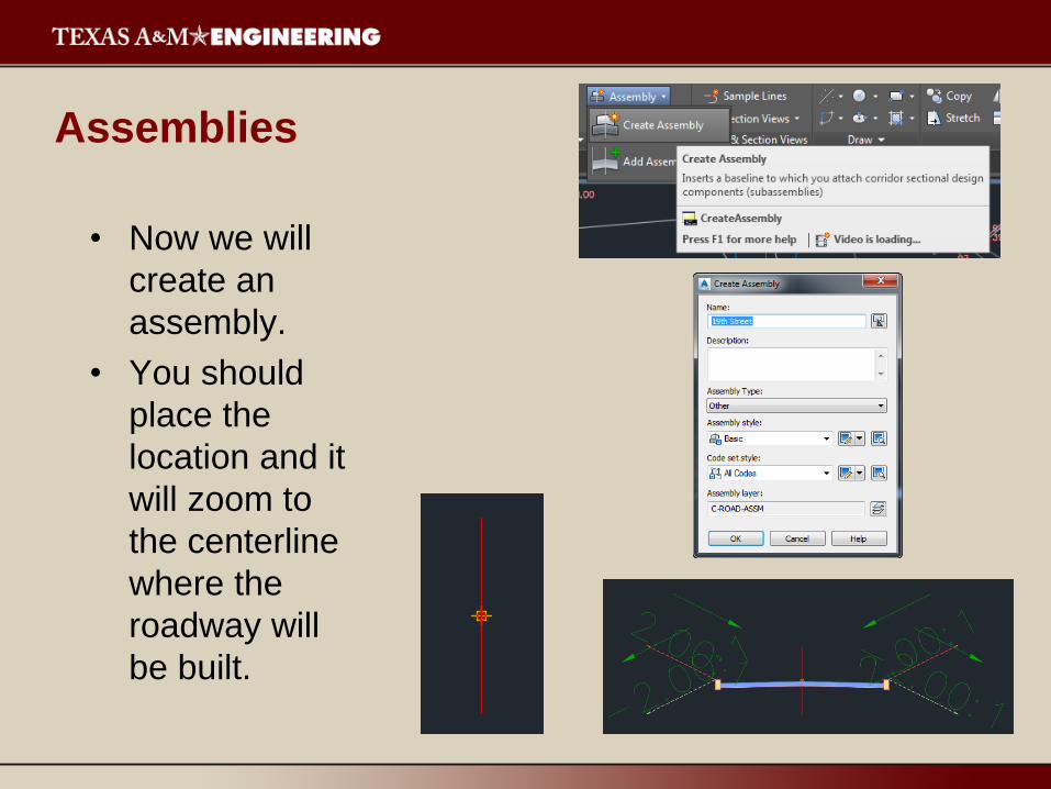
• Now we will
create an
assembly.
• You should
place the
location and it
will zoom to
the centerline
where the
roadway will
be built.
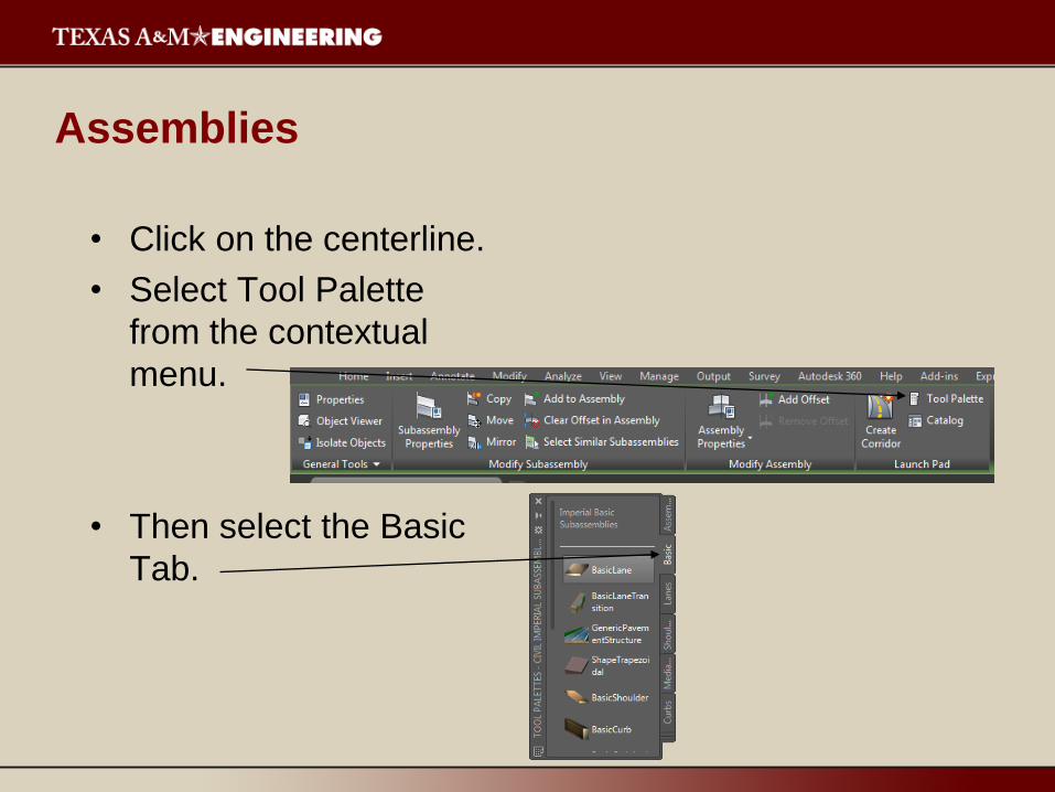
Assemblies
• Click on the centerline.
• Select Tool Palette
from the contextual
menu.
• Then select the Basic
Tab.
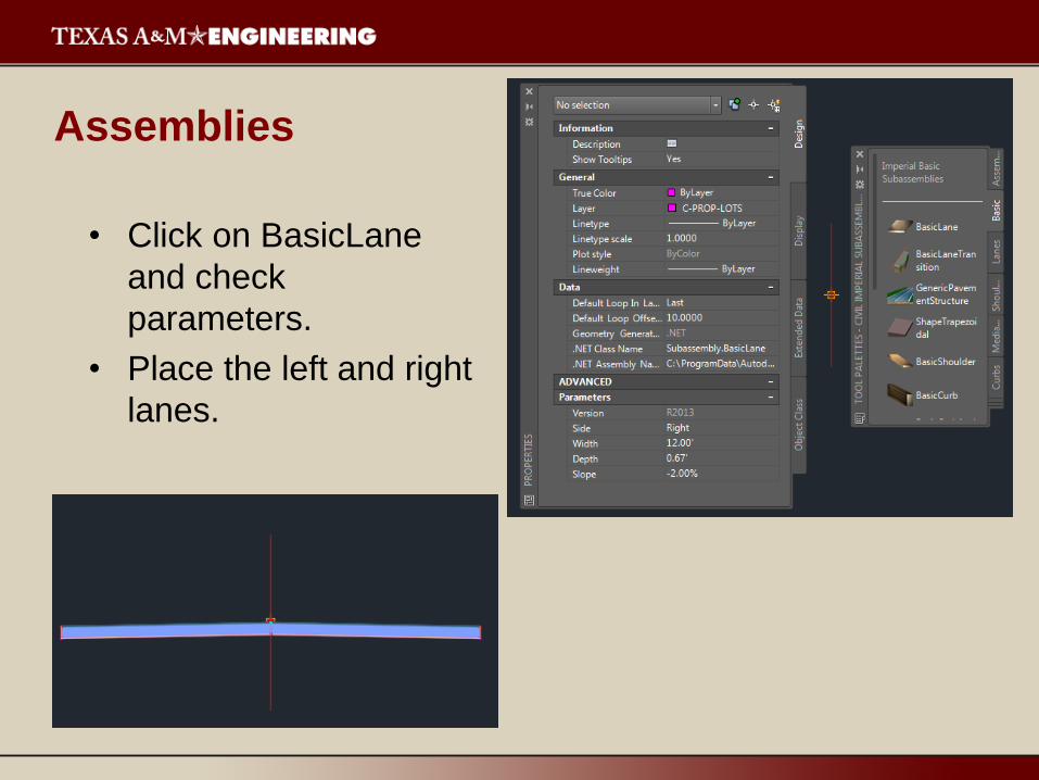
Assemblies
• Click on BasicLane
and check
parameters.
• Place the left and right
lanes.
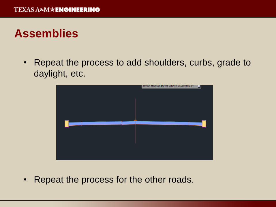
Assemblies
• Repeat the process to add shoulders, curbs, grade to
daylight, etc.
• Repeat the process for the other roads.

Corridors
• Select Corridor.
• Then make sure
alignment, profile, and
assembly correspond.
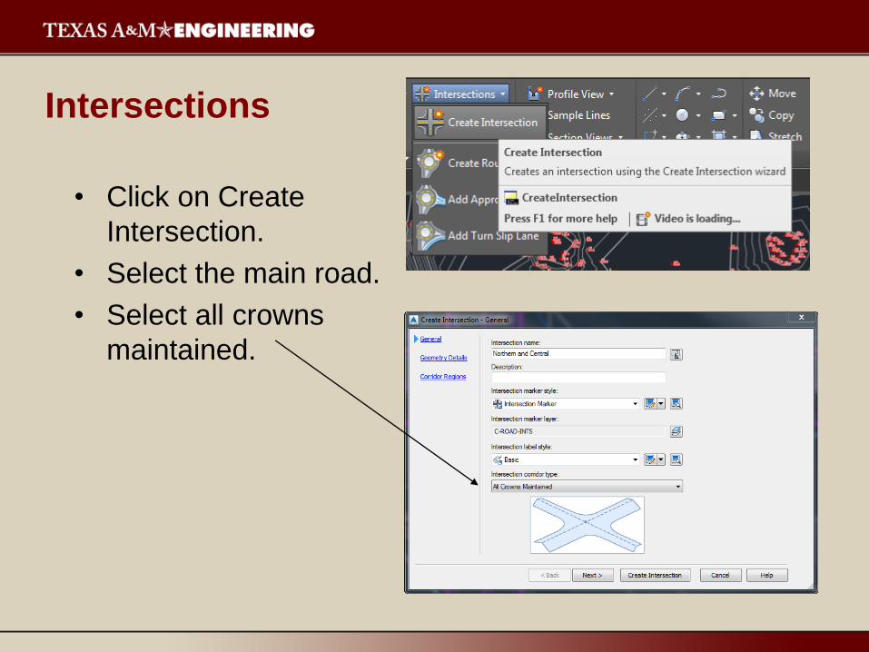
Intersections
• Click on Create
Intersection.
• Select the main road.
• Select all crowns
maintained.
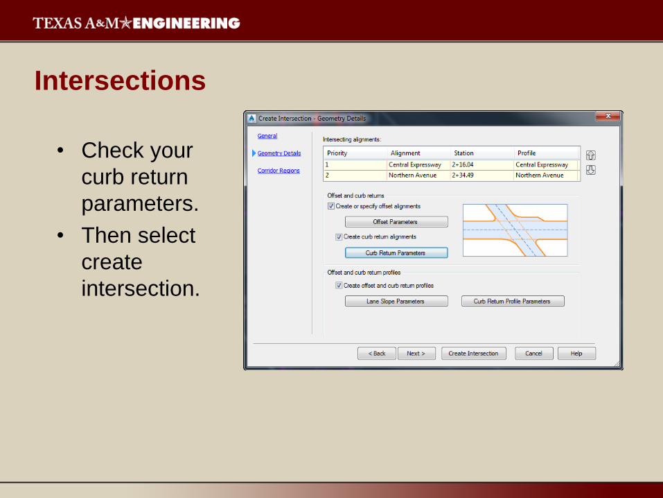
Intersections
• Check your
curb return
parameters.
• Then select
create
intersection.

Intersections
• Intersection
Grading
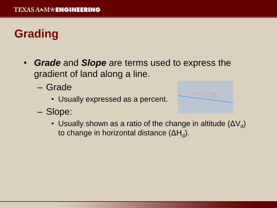
• Grade and Slope are terms used to express the
gradient of land along a line.
– Grade
• Usually expressed as a percent.
– Slope:
• Usually shown as a ratio of the change in altitude (ΔVd)
to change in horizontal distance (ΔHd).
Grading
• Feature Lines
– Complex, linear objects that represent a string of known
elevations, such as the perimeter of your site.
– They can be drawn, or converted from existing objects.
– Store horizontal and elevation location data (similar to 3D
polylines).
– Allow modeling of proposed grading operations.
– Minimize amount of elevation points without compromising
design integrity.
– Stepped Offset command can be used to create new
Feature Line by giving vertical and horizontal offset.
Grading
• Grading Groups
– Collections of Feature Lines that form a contiguous whole.
– Can be used to automatically generate 3D surfaces.
– Surfaces created from Grading Groups will appear in the
Prospector tab.
– Feature Lines and Grading Groups are organized by site.

Grading
• From a previously created
surface:
– Using the Polyline
command, create a border
for your building pad.
• My example was a 200’
square pad located on a point
of interesting topography (not
realistic, but will show grading
more obviously).
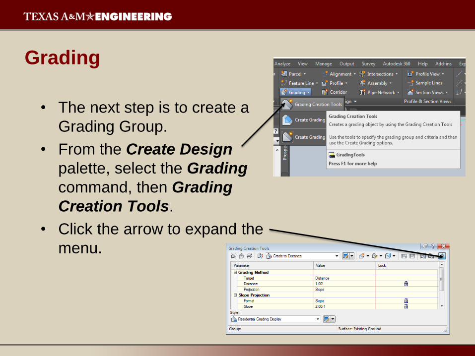
Grading
• The next step is to create a
Grading Group.
• From the Create Design
palette, select the Grading
command, then Grading
Creation Tools.
• Click the arrow to expand the
menu.
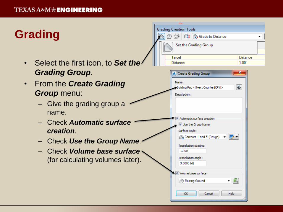
Grading
• Select the first icon, to Set the
Grading Group.
• From the Create Grading
Group menu:
– Give the grading group a
name.
– Check Automatic surface
creation.
– Check Use the Group Name.
– Check Volume base surface
(for calculating volumes later).
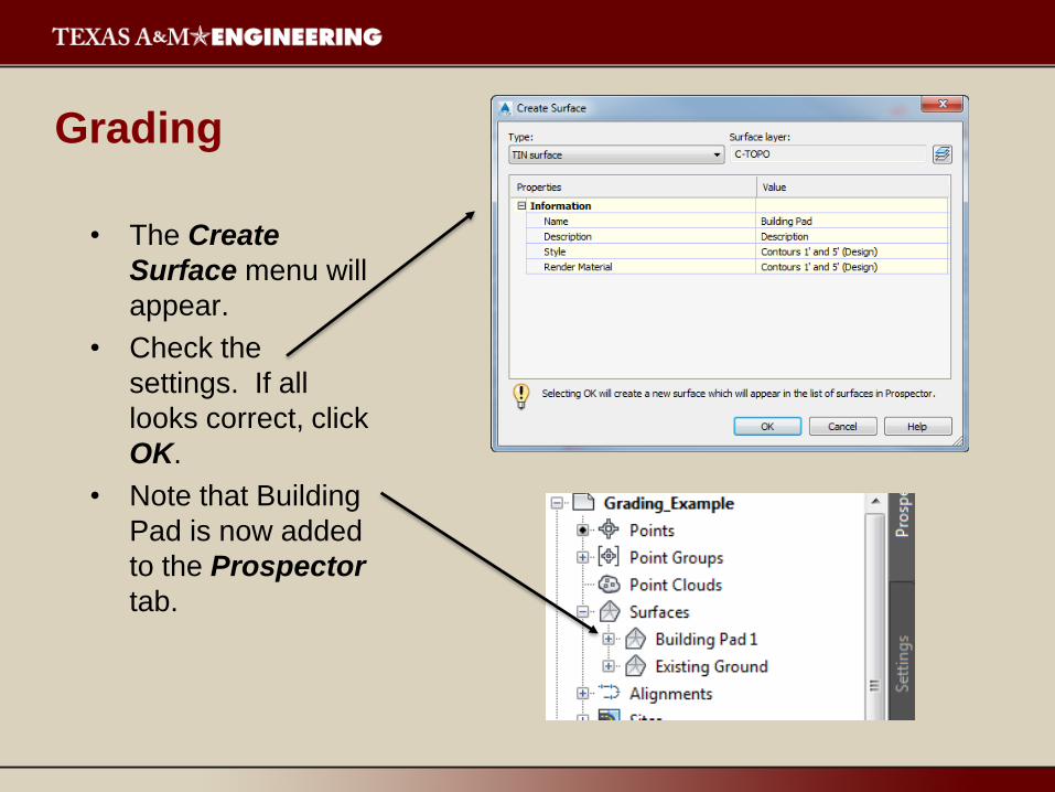
Grading
• The Create
Surface menu will
appear.
• Check the
settings. If all
looks correct, click
OK.
• Note that Building
Pad is now added
to the Prospector
tab.

Grading
• Select the target
surface.
• In our case, we will
grade to the Existing
Ground surface.
• Then, change the
grading criteria to
Grade to Surface.
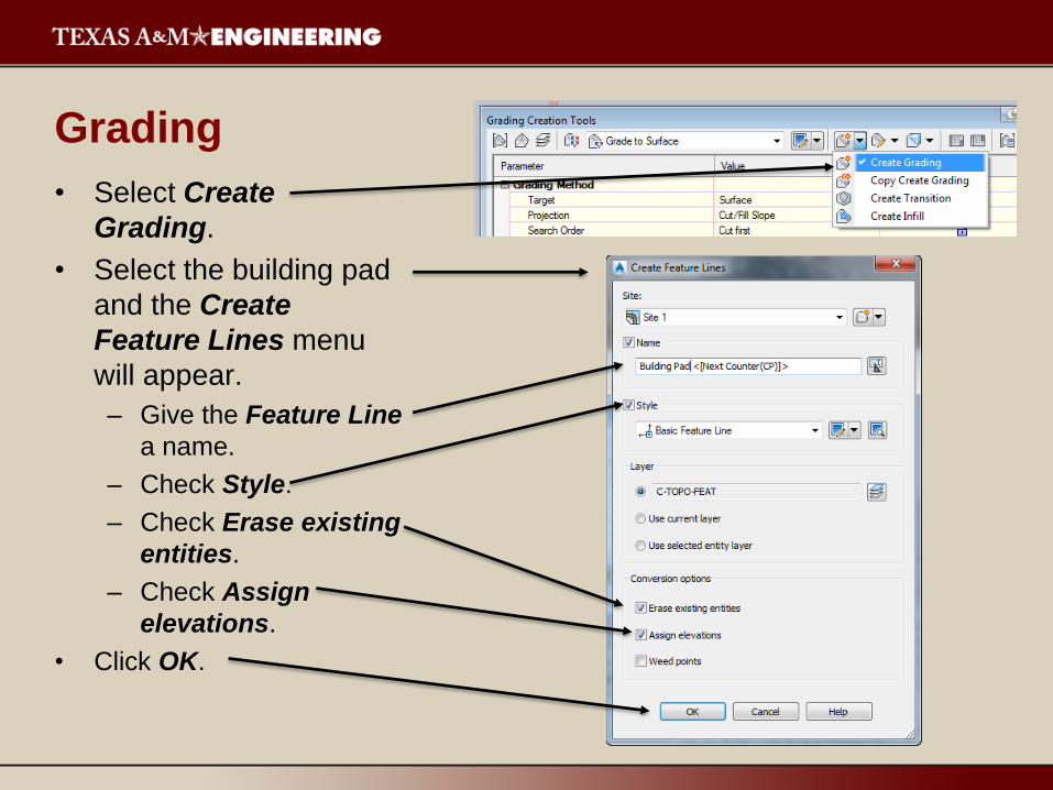
Grading
• Select Create
Grading.
• Select the building pad
and the Create
Feature Lines menu
will appear.
– Give the Feature Line
a name.
– Check Style.
– Check Erase existing
entities.
– Check Assign
elevations.
• Click OK.
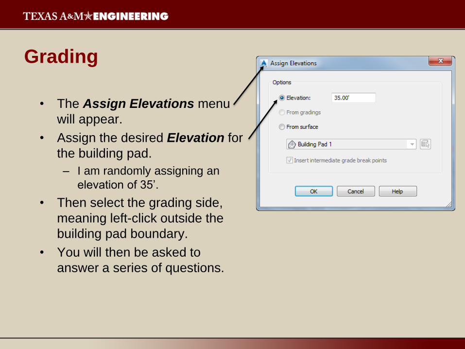
Grading
• The Assign Elevations menu
will appear.
• Assign the desired Elevation for
the building pad.
– I am randomly assigning an
elevation of 35’.
• Then select the grading side,
meaning left-click outside the
building pad boundary.
• You will then be asked to
answer a series of questions.
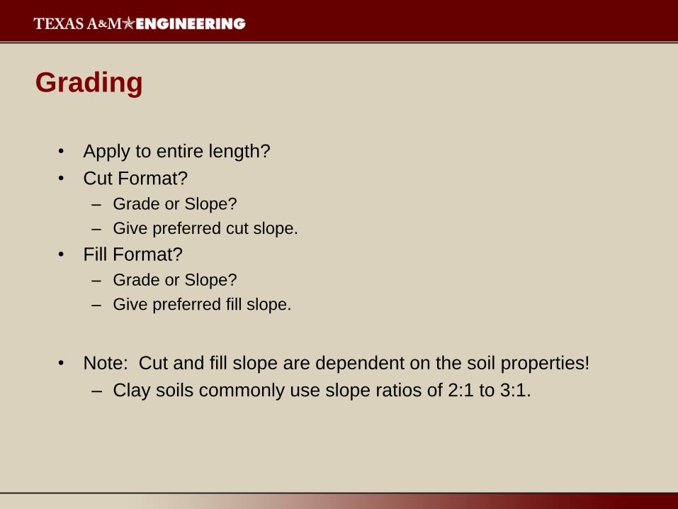
Grading
• Apply to entire length?
• Cut Format?
– Grade or Slope?
– Give preferred cut slope.
• Fill Format?
– Grade or Slope?
– Give preferred fill slope.
• Note: Cut and fill slope are dependent on the soil properties!
– Clay soils commonly use slope ratios of 2:1 to 3:1.
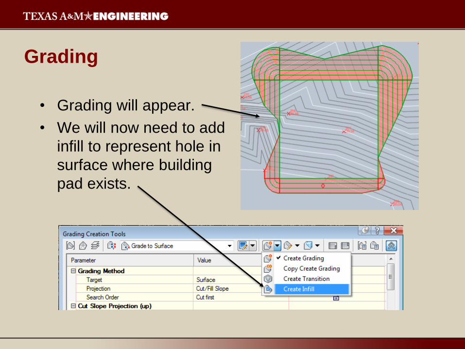
Grading
• Grading will appear.
• We will now need to add
infill to represent hole in
surface where building
pad exists.
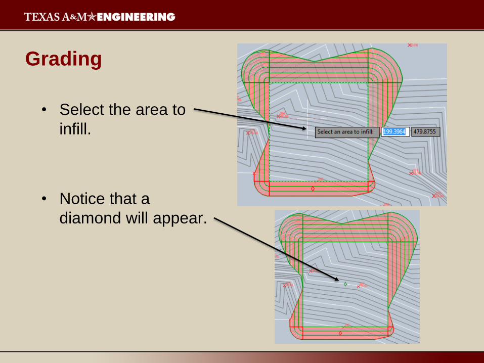
Grading
• Select the area to
infill.
• Notice that a
diamond will appear.
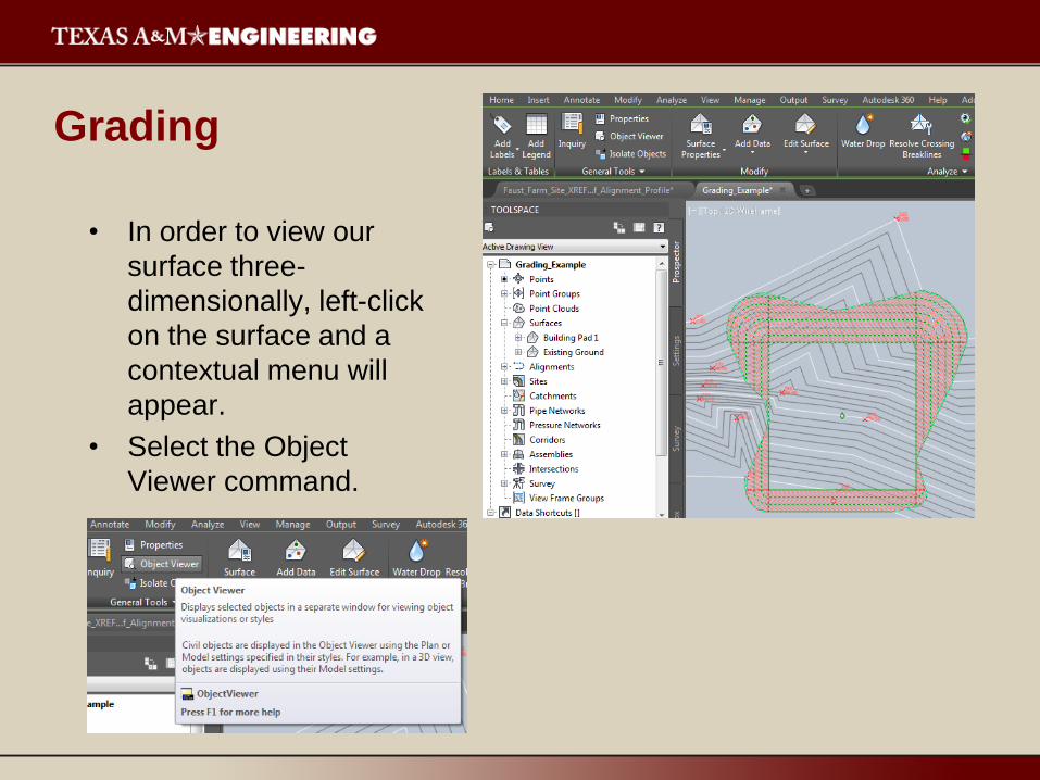
Grading
• In order to view our
surface three-
dimensionally, left-click
on the surface and a
contextual menu will
appear.
• Select the Object
Viewer command.

Grading
• Select Conceptual.
• Using the View Cube,
place the surface in an
orientation that
maximizes your
understanding of the
surface you just
created.
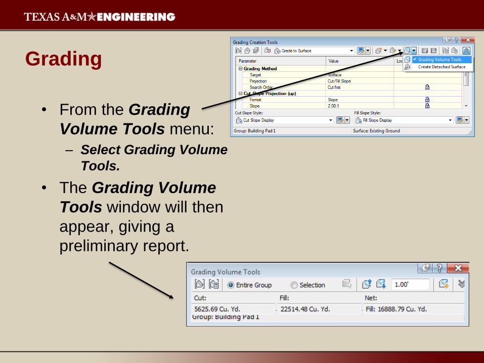
Grading
• From the Grading
Volume Tools menu:
– Select Grading Volume
Tools.
• The Grading Volume
Tools window will then
appear, giving a
preliminary report.

Grading
• Notice that in my
example, the net
amount of earthwork
is 16,888.69 yd3 of fill.
• We can adjust the
building pad level to
balance out the
cut/fill, if design
requirements allow.
– The building pad
may be required to
reside at a set
elevation to remain
above the flood
plain.
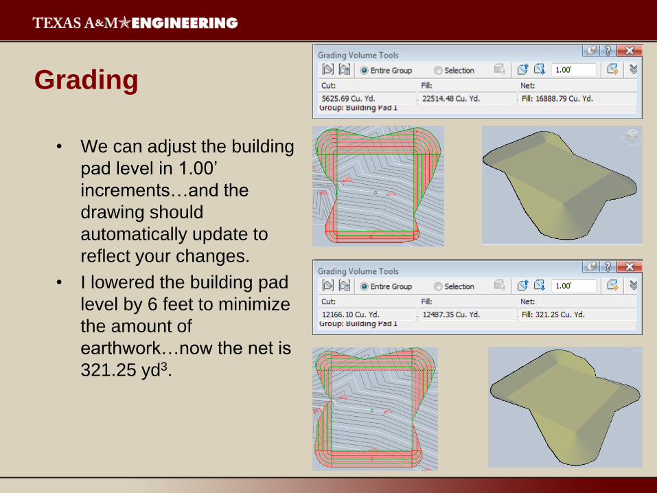
Grading
• We can adjust the building
pad level in 1.00’
increments…and the
drawing should
automatically update to
reflect your changes.
• I lowered the building pad
level by 6 feet to minimize
the amount of
earthwork…now the net is
321.25 yd3.
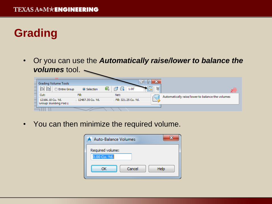
Grading
• Or you can use the Automatically raise/lower to balance the
volumes tool.
• You can then minimize the required volume.
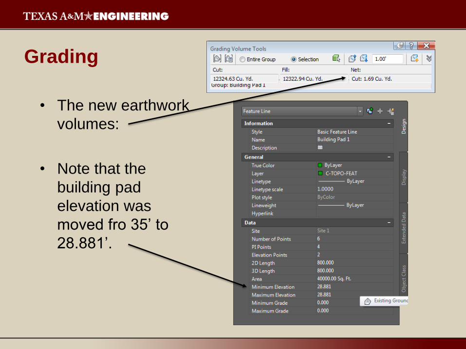
Grading
• The new earthwork
volumes:
• Note that the
building pad
elevation was
moved fro 35’ to
28.881’.
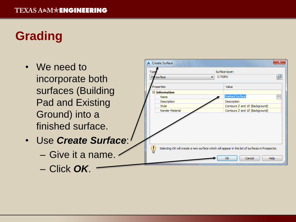
Grading
• We need to
incorporate both
surfaces (Building
Pad and Existing
Ground) into a
finished surface.
• Use Create Surface:
– Give it a name.
– Click OK.
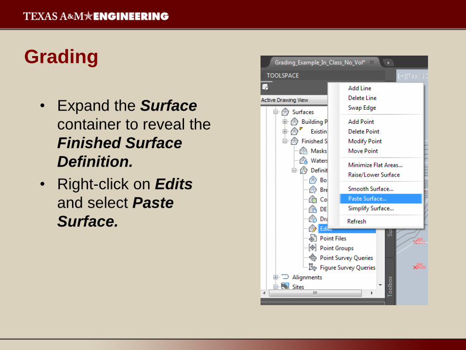
Grading
• Expand the Surface
container to reveal the
Finished Surface
Definition.
• Right-click on Edits
and select Paste
Surface.
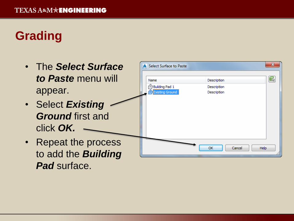
Grading
• The Select Surface
to Paste menu will
appear.
• Select Existing
Ground first and
click OK.
• Repeat the process
to add the Building
Pad surface.

Grading
• At this point, we have
three surfaces, and we
will only display the
finished surface.
• Right-click on the
Existing Ground and
Building Pad surfaces in
Prospector and select
Surface Properties.
• Change the Surface style
to No Display.
• Click Apply and then OK.
Grading
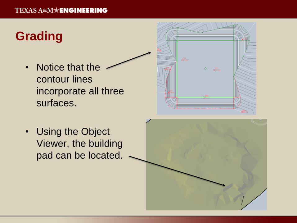
• Notice that the
contour lines
incorporate all three
surfaces.
• Using the Object
Viewer, the building
pad can be located.