city of tampa - dev.tampagov.net · complete wiring diagram and panel elevations for the control...
TRANSCRIPT
CITY OF TAMPA
CONTRACT ADMINISTRATION DEPARTMENT
Michael W. Chucran, Director
306 E. Jackson Street, 4N • Tampa, Florida 33602 • (813) 274-8456 • FAX: (813) 274-8080
Bob Buckhorn, Mayor
ADDENDUM 1
DATE: November 3, 2017
Contract 17-C-00031; Howard F. Curren AWTP Screen and Grit Building 2 Grit Washer Replacement
Bidders on the above referenced project are hereby notified that the following addendum is made to the Contract Documents. BIDS TO BE SUBMITTED SHALL CONFORM TO THIS NOTICE.
Item 1: The Bid Date for the above referenced project is hereby changed to November 21, 2017. Item 2: Update Specification Workmanship and Materials Section 15000 – Piping, General
1. Section 15000-3, 2.02 D. – Replace the paragraph with “Machine bolts shall normally be used on all flanged connections and shall be ASTM A276 Type 316 stainless steel, ASTM A193, Grade B8M passivated bolts with ASTM A194, Grade B8M heavy hex nuts coated to prevent galling, and Type 316 stainless steel washers annealed per ASTM A240. If studs are required, they shall be of the same material as the machine bolts and extend through the nuts a minimum of ¼-inch.”
2. Section 15000-6, 2.06 H. – Delete the words “to the wall of the filter by” in the sentence.
3. Section 15000-6, 2.06 I. – Replace the paragraph with “Manufacturer: Series 2100 MEGAFLANGE Restrained Flange Adapter as produced by EBAA Iron, Inc. or approved equal.”
Item 3: Update Specification Workmanship and Materials Section 32 - Valves
1. Section W-32.09, third paragraph – Replace the words “electric actuators as specified under Section 15106, Actuators, Electric. Electric actuators” with “pneumatic actuators as specified under W-32.12. Pneumatic actuators”.
2. Section W-32.27 Ball Valves for PVC Piping - Manually operated ball valves for PVC piping shall be PVC ball valves having renewable Teflon ball seats and EPDM seals. Ball valves shall block in both seating directions, leaving full pressure on the opposite end of the valve. The PVC ball valves shall be rated at not less than 150 psi working pressure at 75 degrees F, self-lubricating, and shall have socket end connectors. The ball valves shall be of true union design to allow for inspection or removal. PVC ball valves shall be as manufactured by Hayward Industrial Products, Inc., or equal.

Howard F. Curren AWTP Screen and Grit Building 2 Grit Washer Replacement Addendum 1 November 3, 2017 Page 2
3. Section W-32.28 Stainless Steel Ball Valves - Ball valves for use with stainless steel piping systems, including instrument isolation and pneumatic air lines shall be end entry type with type 316 stainless steel body and trim, Teflon seats and seals and end connections as indicated. Valve body shall be either two or three piece design, no internal ring for the ball shall be acceptable. Valves shall be class 150. Valves shall be supplied with stainless steel manual lever or "T" handle. Provide an isolation ball valve on the feed to each pneumatic actuator and for isolation on all instruments. Stainless steel ball valves shall be as manufactured by Janesbury Corporation, Jenkins Bros., Lunkenheimer Flow Control, Wm. Powell Company, Worcester Controls, or equal.
Item 4: Update Specification Workmanship and Materials Section 11412 – Grit Washers
1. Section 11412, 1.02 A. – Insert the word “dual” between the words “include” and “grit” in the second line.
2. Section 11412, 1.03 C. – Replace this paragraph with the following:
C. Submit the following information on the proposed equipment: 1. Complete listing of any deviations, revisions, or exceptions to these specifications or
requirements indicated on the Drawings. 2. Complete catalog information, layout drawings with dimensions and weights, bill of
materials, shipping and handling instructions, and installation instructions for the grit washers.
3. Cut sheets for individual components mounted on the grit washers including valves, solenoids, rotameters, anchor bolts, gear reducer, motor, and proximity switch and other sensors.
4. Complete wiring diagram and panel elevations for the control panel along with cut sheets for all individual panel components including the panel itself, PLC components, breakers, VFDs, OIU, UPS, network switch, louvers and fans, phase and load monitors, control devices, surge devices, terminal blocks, relays, etc.
5. Spare parts list 6. Programming description, sample OIU display showing proposed operator interface
features, and complete PLC address/register listing for interface with the Grit Removal System Main Control Panel.
7. Proposed testing procedures for field and performance tests. 8. As-built drawings and O&M materials upon startup
3. Section 11412, 2.03 B. – replace the words “to a stable base” and the last sentence with the following “to the existing concrete floor. Anchors shall be sized and provided by the manufacturer and shall be epoxy set, Type 316 stainless steel concrete anchor bolts, nuts, and washers set with Type 316 leveling nuts on a minimum of 1” grout below the equipment base plates.”
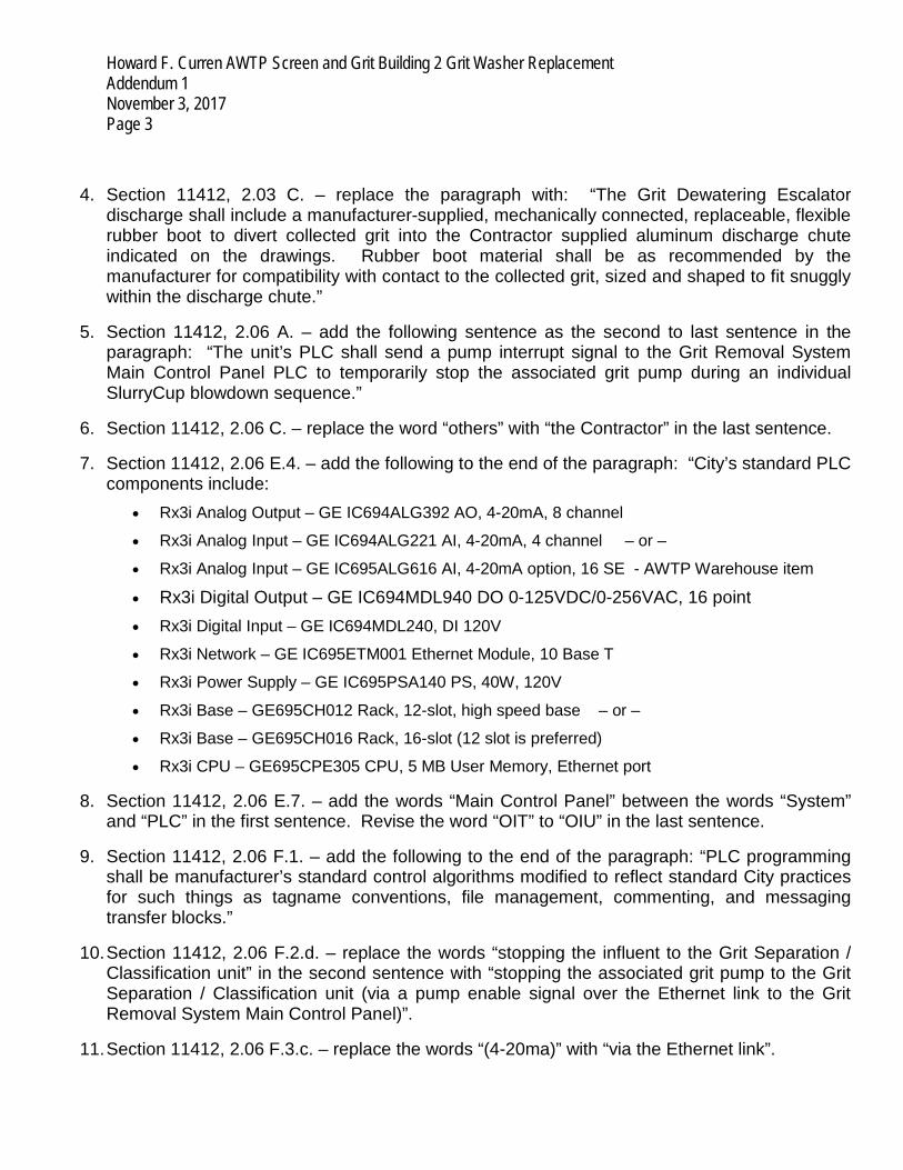
Howard F. Curren AWTP Screen and Grit Building 2 Grit Washer Replacement Addendum 1 November 3, 2017 Page 3
4. Section 11412, 2.03 C. – replace the paragraph with: “The Grit Dewatering Escalator discharge shall include a manufacturer-supplied, mechanically connected, replaceable, flexible rubber boot to divert collected grit into the Contractor supplied aluminum discharge chute indicated on the drawings. Rubber boot material shall be as recommended by the manufacturer for compatibility with contact to the collected grit, sized and shaped to fit snuggly within the discharge chute.”
5. Section 11412, 2.06 A. – add the following sentence as the second to last sentence in the paragraph: “The unit’s PLC shall send a pump interrupt signal to the Grit Removal System Main Control Panel PLC to temporarily stop the associated grit pump during an individual SlurryCup blowdown sequence.”
6. Section 11412, 2.06 C. – replace the word “others” with “the Contractor” in the last sentence.
7. Section 11412, 2.06 E.4. – add the following to the end of the paragraph: “City’s standard PLC components include:
• Rx3i Analog Output – GE IC694ALG392 AO, 4-20mA, 8 channel
• Rx3i Analog Input – GE IC694ALG221 AI, 4-20mA, 4 channel – or –
• Rx3i Analog Input – GE IC695ALG616 AI, 4-20mA option, 16 SE - AWTP Warehouse item
• Rx3i Digital Output – GE IC694MDL940 DO 0-125VDC/0-256VAC, 16 point • Rx3i Digital Input – GE IC694MDL240, DI 120V
• Rx3i Network – GE IC695ETM001 Ethernet Module, 10 Base T
• Rx3i Power Supply – GE IC695PSA140 PS, 40W, 120V
• Rx3i Base – GE695CH012 Rack, 12-slot, high speed base – or –
• Rx3i Base – GE695CH016 Rack, 16-slot (12 slot is preferred)
• Rx3i CPU – GE695CPE305 CPU, 5 MB User Memory, Ethernet port
8. Section 11412, 2.06 E.7. – add the words “Main Control Panel” between the words “System” and “PLC” in the first sentence. Revise the word “OIT” to “OIU” in the last sentence.
9. Section 11412, 2.06 F.1. – add the following to the end of the paragraph: “PLC programming shall be manufacturer’s standard control algorithms modified to reflect standard City practices for such things as tagname conventions, file management, commenting, and messaging transfer blocks.”
10. Section 11412, 2.06 F.2.d. – replace the words “stopping the influent to the Grit Separation / Classification unit” in the second sentence with “stopping the associated grit pump to the Grit Separation / Classification unit (via a pump enable signal over the Ethernet link to the Grit Removal System Main Control Panel)”.
11. Section 11412, 2.06 F.3.c. – replace the words “(4-20ma)” with “via the Ethernet link”.

Howard F. Curren AWTP Screen and Grit Building 2 Grit Washer Replacement Addendum 1 November 3, 2017 Page 4
12. Section 11412, 2.06 H.1. – add the following to the paragraph: “Register/Address signals to/from the Grit Removal System Main Control Panel PLC from each Grit Washer PLC shall include, as a minimum, the following:
• Individual SlurryCup enable/call to run for both units from the main PLC • Individual SlurryCup ready for both units to the main PLC. • SlurryCup running for both units • SlurryCup in blowdown for both units (interlock to stop associated grit pump) • SlurryCup in backwash for both units • UPS status as noted below • VFD status/control as noted below • PLC and network switch faults”
13. Section 11412, 2.06 H.2. - Revise the word “OIT” to “OIU”.
14. Section 11412, 2.07 B. and C. – replace the words “wooden boxes” with “cardboard boxes” in paragraph B. and delete paragraph C.
15. Section 11412, 3.03 A. – revise the number of days/trips for performance testing in the table from “2” to “5”.
Item 5: Update Specification Workmanship and Materials Section 17000 – Instrumentation Requirements
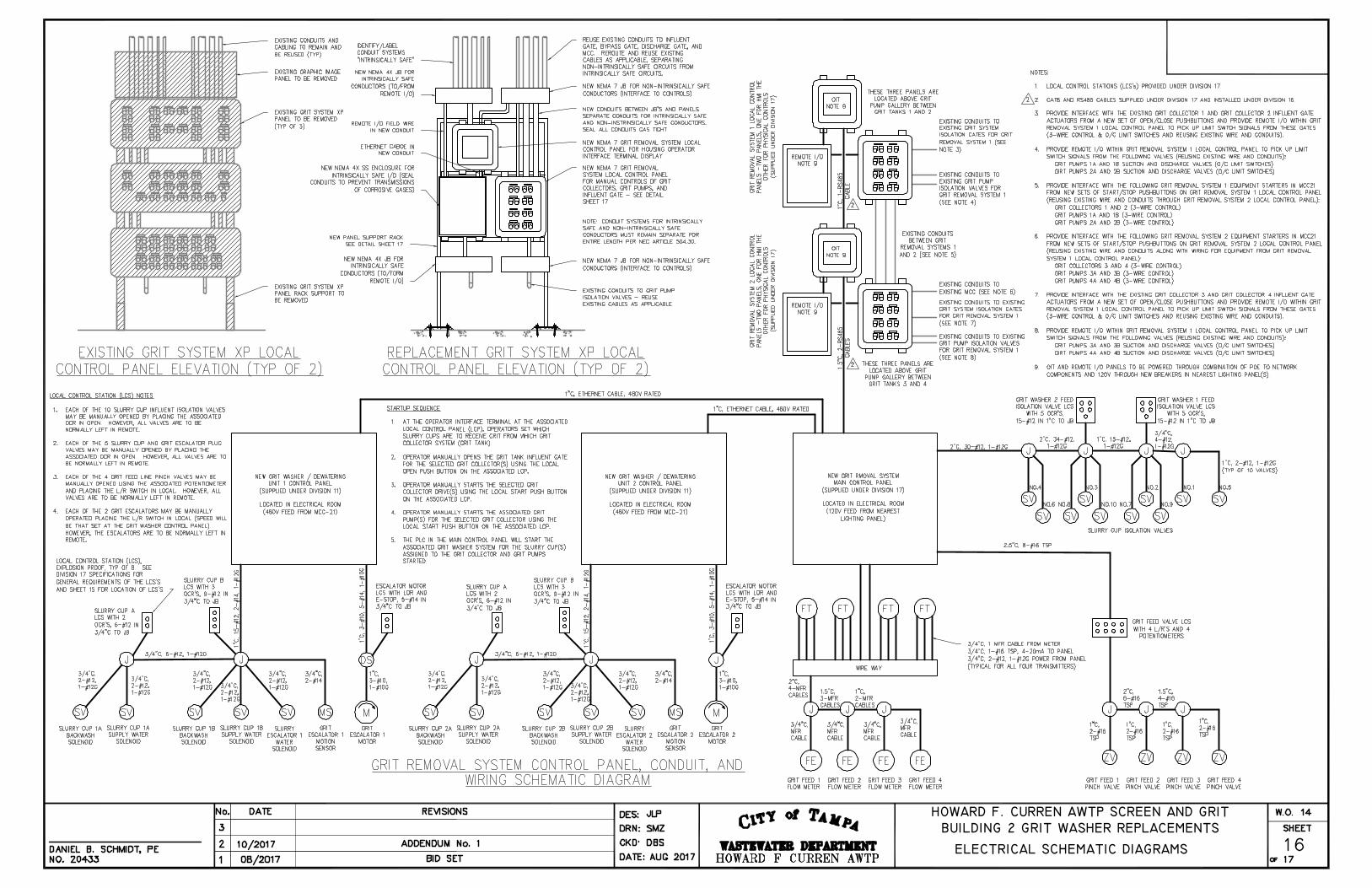
1. Section 17000, 1.05 A. – Add paragraph 16 to read: “Complete network diagram showing all network communications to PLCs, VFDs, UPSs, OIUs, OITs, remote I/O, network switches, and CAT6 and RS485 cables, protocols used, components used, and conduit sizes between panels. Coordinate with the grit washer manufacturer to include components supplied within the vendor panels in the submitted network diagram for a complete network description.”
2. Section 17000, 1.06 A.2. – add the words “– use by the Operator Interface Unit (OIT) –” between the words “(OIS)” and “and”.
3. Section 17000, 2.01 J.3. – Revise the words “grit removal system Human-Machine Interface (HMI)” to read “plant SCADA system”. Add the words “, through the OIT,”. Add the following to the end of the paragraph: “City’s standard PLC components include:
• Rx3i Analog Output – GE IC694ALG392 AO, 4-20mA, 8 channel
• Rx3i Analog Input – GE IC694ALG221 AI, 4-20mA, 4 channel – or –
• Rx3i Analog Input – GE IC695ALG616 AI, 4-20mA option, 16 SE - AWTP Warehouse item
• Rx3i Digital Output – GE IC694MDL940 DO 0-125VDC/0-256VAC, 16 point • Rx3i Digital Input – GE IC694MDL240, DI 120V
• Rx3i Network – GE IC695ETM001 Ethernet Module, 10 Base T
• Rx3i Power Supply – GE IC695PSA140 PS, 40W, 120V
• Rx3i Base – GE695CH012 Rack, 12-slot, high speed base – or –

Howard F. Curren AWTP Screen and Grit Building 2 Grit Washer Replacement Addendum 1 November 3, 2017 Page 5
• Rx3i Base – GE695CH016 Rack, 16-slot (12 slot is preferred)
• Rx3i CPU – GE695CPE305 CPU, 5 MB User Memory, Ethernet port
4. Section 17000, 2.01 J.7. – add the words “and the local area network switch” to the end of the first sentence.
5. Section 17000, 2.01 J.8. – Revise the paragraph to read: “Interface to Grit Removal System Local Panel OIT and I/O: Communication between the Grit Removal System Local intrinsically safe Remote I/O and Operator Interface Terminal (OIT) shall be by Ethernet via high quality, shielded CAT6 cable. Communication between the OIT and Grit Removal System Main Control Panel shall be by RS485 physical layer and Modbus RTU application layer via shielded 1-1/2 pair RS485 cable, Belden 3106A or equal. The conduit between panels shall be furnished and installed under Division 16. A separate RS485 cable and conduit shall be provided and installed between each Local OIT and the Main Control Panel. All cables shall be supplied by the INSTRUMENTATION SUBCONTRACTOR, installed under Division 16.”
6. Section17000, 2.01 J.9. – Revise the paragraph to read: “Local Area Network Switch and SCADA Interface Network Switch: Ethernet interface components within the Grit Removal Main Control Panel shall be through a local area network switch, Stratix 5700 or equal. The minimum 10-port local area network switch shall provide communications with City-assigned IP addresses for the Grit Washer Control Panel PLC interfaces and the Grit Removal System Main Control Panel PLC and UPS. Cable between the network switch and the PLC and UPS within the panel shall be through industrial grade CAT6 cable and ST connectors. Communications between the Grit Removal System Main Control Panel PLC and the existing SCADA RTU shall be by RS485 physical layer and Modbus RTU application layer via shielded 1-1/2 pair RS485 cable, Belden 3106A or equal. Provide a new 4-port serial communication module #GEIC695CMM004 to replace the existing 2-port #GEIC695CMM002 module in the existing SCADA RTU PLC. The proposed RS485 cable from the Main Grit Control Panel shall be connected to this module. Modifications to the existing RTU PLC will be made by City Personnel. City Personnel will assist the Integrator with the required Modbus Register Mapping for the existing SCADA RTU. The conduit between panels shall be furnished and installed under Division 16. All cables shall be supplied by the INSTRUMENTATION SUBCONTRACTOR, installed under Division 16.”
7. Section 17000, 2.02 A.5. – Add the following to the end of the paragraph: “When a blowdown / SlurryCup disabled signal from one of the Grit Washer Control Panel PLCs is received, the associated Grit Pump feeding that SlurryCup shall be stopped.”
8. Section 17000, 2.02 C., on page 18 – Add the following to the end of the paragraph just before paragraph D.: “Grit Washer Ethernet Link I/O: Register/Address signals to/from the Grit Removal System Main Control Panel PLC from each Grit Washer PLC shall include, as a minimum, the following:
• Individual SlurryCup enable/call to run for both units from the main PLC • Individual SlurryCup ready for both units (permissive to operate associated grit pump) to
the main PLC. • SlurryCup running for both units

Howard F. Curren AWTP Screen and Grit Building 2 Grit Washer Replacement Addendum 1 November 3, 2017 Page 6
• SlurryCup in blowdown for both units (interlocked to stop associated grit pump during blowdown sequence)
• SlurryCup in backwash for both units • UPS running on battery, % battery life left value, and fault • VFD running input, speed output, speed input, run command output, and fault • PLC and network switch faults”
9. Section 17000, page 19 – Add paragraph 2.05 to read: “2.05 Plant SCADA Interface: City personnel will program plant work station displays to allow
remote status monitoring and control of the upgraded grit removal system. All data registers / addresses developed under this project shall be made accessible for remote display and interface to allow operators to monitor and control the system from plant work stations.”
Item 6: Replace Plan Sheet 14 Grit Unit Electrical Lower Plan with the attached Plan Sheet 14. Item 7: Replace Plan Sheet 16 Electrical Schematic Diagram with the attached Plan Sheet 16. Item 8: Attached for reference is the pre-bid meeting sign-in sheet
All other provisions of the Contract Documents and Specifications not in conflict with this Addendum shall remain in full force and effect. Questions are to be e-mailed to Contract [email protected]. Jim Greiner Jim Greiner, P.E., Contract Management Supervisor

GRIT UNIT ELECTRICAL LOWER PLAN
HOWARD F. CURREN AWTP SCREEN AND GRITBUILDING 2 GRIT WASHER REPLACEMENTS
HOWARD F. CURREN AWTP SCREEN AND GRITBUILDING 2 GRIT WASHER REPLACEMENTS
ELECTRICAL SCHEMATIC DIAGRAMS
