cisco unified web and e-mail interaction manager ......cisco unified e-mail interaction manager...
TRANSCRIPT
Cisco Unified Web and E-Mail Interaction Manager Deployment and Maintenance GuideFor Unified Contact Center Enterprise
Release 9.0(1)March 2013
Americas HeadquartersCisco Systems, Inc.170 West Tasman DriveSan Jose, CA 95134-1706 USAhttp://www.cisco.comTel: 408 526-4000
800 553-NETS (6387)Fax: 408 527-0883

THE SPECIFICATIONS AND INFORMATION REGARDING THE PRODUCTS IN THIS MANUAL ARE SUBJECT TO CHANGE WITHOUT NOTICE. ALL STATEMENTS, INFORMATION, AND RECOMMENDATIONS IN THIS MANUAL ARE BELIEVED TO BE ACCURATE BUT ARE PRESENTED WITHOUT WARRANTY OF ANY KIND, EXPRESS OR IMPLIED. USERS MUST TAKE FULL RESPONSIBILITY FOR THEIR APPLICATION OF ANY PRODUCTS.
THE SOFTWARE LICENSE AND LIMITED WARRANTY FOR THE ACCOMPANYING PRODUCT ARE SET FORTH IN THE INFORMATION PACKET THAT SHIPPED WITH THE PRODUCT AND ARE INCORPORATED HEREIN BY THIS REFERENCE. IF YOU ARE UNABLE TO LOCATE THE SOFTWARE LICENSE OR LIMITED WARRANTY, CONTACT YOUR CISCO REPRESENTATIVE FOR A COPY.
The Cisco implementation of TCP header compression is an adaptation of a program developed by the University of California, Berkeley (UCB) as part of UCBs public domain version of the UNIX operating system. All rights reserved. Copyright 1981, Regents of the University of California.
NOTWITHSTANDING ANY OTHER WARRANTY HEREIN, ALL DOCUMENT FILES AND SOFTWARE OF THESE SUPPLIERS ARE PROVIDED "AS IS" WITH ALL FAULTS. CISCO AND THE ABOVE-NAMED SUPPLIERS DISCLAIM ALL WARRANTIES, EXPRESSED OR IMPLIED, INCLUDING, WITHOUT LIMITATION, THOSE OF MERCHANTABILITY, FITNESS FOR A PARTICULAR PURPOSE AND NONINFRINGEMENT OR ARISING FROM A COURSE OF DEALING, USAGE, OR TRADE PRACTICE.
IN NO EVENT SHALL CISCO OR ITS SUPPLIERS BE LIABLE FOR ANY INDIRECT, SPECIAL, CONSEQUENTIAL, OR INCIDENTAL DAMAGES, INCLUDING, WITHOUT LIMITATION, LOST PROFITS OR LOSS OR DAMAGE TO DATA ARISING OUT OF THE USE OR INABILITY TO USE THIS MANUAL, EVEN IF CISCO OR ITS SUPPLIERS HAVE BEEN ADVISED OF THE POSSIBILITY OF SUCH DAMAGES.
Cisco and the Cisco logo are trademarks or registered trademarks of Cisco and/or its affiliates in the U.S. and other countries. To view a list of Cisco trademarks, go to http://www.cisco.com/go/trademarks
CCVP, the Cisco logo, and Welcome to the Human Network are trademarks of Cisco Systems, Inc.; Changing the Way We Work, Live, Play, and Learn is a service mark of Cisco Systems, Inc.; and Access Registrar, Aironet, Catalyst, CCDA, CCDP, CCIE, CCIP, CCNA, CCNP, CCSP, Cisco, the Cisco Certified Internetwork Expert logo, Cisco IOS, Cisco Press, Cisco Systems, Cisco Systems Capital, the Cisco Systems logo, Cisco Unity, Enterprise/Solver, EtherChannel, EtherFast, EtherSwitch, Fast Step, Follow Me Browsing, FormShare, GigaDrive, HomeLink, Internet Quotient, IOS, iPhone, IP/TV, iQ Expertise, the iQ logo, iQ Net Readiness Scorecard, iQuick Study, LightStream, Linksys, MeetingPlace, MGX, Networkers, Networking Academy, Network Registrar, PIX, ProConnect, ScriptShare, SMARTnet, StackWise, The Fastest Way to Increase Your Internet Quotient, and TransPath are registered trademarks of Cisco Systems, Inc. and/or its affiliates in the United States and certain other countries. Any Internet Protocol (IP) addresses used in this document are not intended to be actual addresses. Any examples, command display output, and figures included in the document are shown for illustrative purposes only. Any use of actual IP addresses in illustrative content is unintentional and coincidental.
Third-party trademarks mentioned are the property of their respective owners. The use of the word partner does not imply a partnership relationship between Cisco and any other company. (1110R)
Cisco Unified Web and E-Mail Interaction Manager Deployment and Maintenance Guide: For Unified Contact Center Enterprise. March 20, 2013.
Copyright © 2013, Cisco Systems, Inc. All rights reserved.
Contents
Preface .................................................................................................................................................7
About This Guide . . . . . . . . . . . . . . . . . . . . . . . . . . . . . . . . . . . . . . . . . . . . . . . . . . . . . . . . 8
Document Conventions. . . . . . . . . . . . . . . . . . . . . . . . . . . . . . . . . . . . . . . . . . . . . . . . . . . . 8
Other Learning Resources. . . . . . . . . . . . . . . . . . . . . . . . . . . . . . . . . . . . . . . . . . . . . . . . . . 9
Online Help . . . . . . . . . . . . . . . . . . . . . . . . . . . . . . . . . . . . . . . . . . . . . . . . . . . . . . . . . . 9
Documentation . . . . . . . . . . . . . . . . . . . . . . . . . . . . . . . . . . . . . . . . . . . . . . . . . . . . . . . 9
Chapter 1: Preparing Unified CCE for the Integration................................................................11
Relationship Between Objects in Unified CCE and Unified EIM and WIM . . . . . . . . . . 12
Designing Your Installation . . . . . . . . . . . . . . . . . . . . . . . . . . . . . . . . . . . . . . . . . . . . . . . 12
Obtaining Unified EIM and WIM Licenses . . . . . . . . . . . . . . . . . . . . . . . . . . . . . . . . . . . 12
Installing Unified CCE . . . . . . . . . . . . . . . . . . . . . . . . . . . . . . . . . . . . . . . . . . . . . . . . . . . 13
Setting up Agent Desktops for Voice Call Routing . . . . . . . . . . . . . . . . . . . . . . . . . . . . . 13
Configuring Cisco Unified Communication Manager for Routing Voice Calls . . . . . . . 14
Planning Unified CCE Configuration . . . . . . . . . . . . . . . . . . . . . . . . . . . . . . . . . . . . . . . . 18
Configuring Unified CCE . . . . . . . . . . . . . . . . . . . . . . . . . . . . . . . . . . . . . . . . . . . . . . . . . 19
Configuring Application Instance . . . . . . . . . . . . . . . . . . . . . . . . . . . . . . . . . . . . . . . . 19
About Media Classes. . . . . . . . . . . . . . . . . . . . . . . . . . . . . . . . . . . . . . . . . . . . . . . . . . 20
Important Note About Media Classes . . . . . . . . . . . . . . . . . . . . . . . . . . . . . . . . . 21
Configuring Media Classes . . . . . . . . . . . . . . . . . . . . . . . . . . . . . . . . . . . . . . . . . . . . . 21
Configuring Media Routing Domains (MRDs) . . . . . . . . . . . . . . . . . . . . . . . . . . . . . 23
Configuring Network VRU. . . . . . . . . . . . . . . . . . . . . . . . . . . . . . . . . . . . . . . . . . . . . 24
Configuring Network VRU Scripts. . . . . . . . . . . . . . . . . . . . . . . . . . . . . . . . . . . . . . . 25
Configuring Call Types. . . . . . . . . . . . . . . . . . . . . . . . . . . . . . . . . . . . . . . . . . . . . . . . 26
Configuring Media Routing Peripheral Gateways (MR PGs) . . . . . . . . . . . . . . . . . . 27
Configuring Agent Desk Settings . . . . . . . . . . . . . . . . . . . . . . . . . . . . . . . . . . . . . . . . 31
Configuring Agent Peripheral Gateway (Agent PG) . . . . . . . . . . . . . . . . . . . . . . . . . 32
Configuring Network Trunk Group . . . . . . . . . . . . . . . . . . . . . . . . . . . . . . . . . . . . . . 34
Configuring Application Path . . . . . . . . . . . . . . . . . . . . . . . . . . . . . . . . . . . . . . . . . . . 35
Configuring Agents . . . . . . . . . . . . . . . . . . . . . . . . . . . . . . . . . . . . . . . . . . . . . . . . . . . 37
Configuring Skill Groups . . . . . . . . . . . . . . . . . . . . . . . . . . . . . . . . . . . . . . . . . . . . . . 38
Contents 3
Configuring Labels . . . . . . . . . . . . . . . . . . . . . . . . . . . . . . . . . . . . . . . . . . . . . . . . . . . 42
Configuring Script Selectors . . . . . . . . . . . . . . . . . . . . . . . . . . . . . . . . . . . . . . . . . . . . 43
Creating Scripts . . . . . . . . . . . . . . . . . . . . . . . . . . . . . . . . . . . . . . . . . . . . . . . . . . . . . . 45
Configuring Device Targets . . . . . . . . . . . . . . . . . . . . . . . . . . . . . . . . . . . . . . . . . . . . 50
Configuring Expanded Call Context (ECC) Variables . . . . . . . . . . . . . . . . . . . . . . . . 51
Installing Unified EIM and WIM and the Integration . . . . . . . . . . . . . . . . . . . . . . . . . . . 52
Preparing Cisco Media Blender for the Integration . . . . . . . . . . . . . . . . . . . . . . . . . . . . . 53
Installing Cisco Media Blender. . . . . . . . . . . . . . . . . . . . . . . . . . . . . . . . . . . . . . . . . . 53
Configuring Cisco Media Blender . . . . . . . . . . . . . . . . . . . . . . . . . . . . . . . . . . . . . . . 53
Configuring Cisco Media Blender for Unified CCE. . . . . . . . . . . . . . . . . . . . . . 53
Configuring the System for Multiple Agent PGs . . . . . . . . . . . . . . . . . . . . . . . . . . . . . . . 57
Configuring Finesse . . . . . . . . . . . . . . . . . . . . . . . . . . . . . . . . . . . . . . . . . . . . . . . . . . . . . 58
Chapter 2: Setting Up Integrated Objects ....................................................................................61
Configuring Variables in Unified EIM and WIM. . . . . . . . . . . . . . . . . . . . . . . . . . . . . . . 62
Verifying Mapping of Objects in the Administration Console. . . . . . . . . . . . . . . . . . . . . 62
Setting Up Knowledge Base Articles for Unified EIM . . . . . . . . . . . . . . . . . . . . . . . . . . 63
Setting up Business Objects in the Administration Console. . . . . . . . . . . . . . . . . . . . . . . 64
Unified EIM Objects . . . . . . . . . . . . . . . . . . . . . . . . . . . . . . . . . . . . . . . . . . . . . . . . . . 64
Unified WIM Objects . . . . . . . . . . . . . . . . . . . . . . . . . . . . . . . . . . . . . . . . . . . . . . . . . 64
Setting Up Services in the System Console . . . . . . . . . . . . . . . . . . . . . . . . . . . . . . . . . . . 65
Unified EIM Services . . . . . . . . . . . . . . . . . . . . . . . . . . . . . . . . . . . . . . . . . . . . . . . . . 65
Unified WIM Services . . . . . . . . . . . . . . . . . . . . . . . . . . . . . . . . . . . . . . . . . . . . . . . . 66
Setting Up Web Links for Chat and Collaboration. . . . . . . . . . . . . . . . . . . . . . . . . . . . . . 67
Configuring Dynamic Messages for Integrated Chats . . . . . . . . . . . . . . . . . . . . . . . . . . . 67
Handling Email Assignment . . . . . . . . . . . . . . . . . . . . . . . . . . . . . . . . . . . . . . . . . . . . . . . 70
Related Documentation. . . . . . . . . . . . . . . . . . . . . . . . . . . . . . . . . . . . . . . . . . . . . . . . . . . 70
Chapter 3: Managing and Maintaining Servers..........................................................................72
Encrypting SQL Server Database . . . . . . . . . . . . . . . . . . . . . . . . . . . . . . . . . . . . . . . . . . . 73
Best Practices for Configuring Servers. . . . . . . . . . . . . . . . . . . . . . . . . . . . . . . . . . . . . . . 74
For All Servers . . . . . . . . . . . . . . . . . . . . . . . . . . . . . . . . . . . . . . . . . . . . . . . . . . . . . . 74
Allocating Adequate Virtual Memory. . . . . . . . . . . . . . . . . . . . . . . . . . . . . . . . . 74
Setting Up Disk Space. . . . . . . . . . . . . . . . . . . . . . . . . . . . . . . . . . . . . . . . . . . . . 75
4 Cisco Unified Web and E-Mail Interaction Manager Deployment and Maintenance Guide

Configuring Anti-virus Protection. . . . . . . . . . . . . . . . . . . . . . . . . . . . . . . . . . . . 75
Additional Best Practices for Database Servers . . . . . . . . . . . . . . . . . . . . . . . . . . . . . 75
Installation and Settings . . . . . . . . . . . . . . . . . . . . . . . . . . . . . . . . . . . . . . . . . . . 75
Optimal Configuration Settings. . . . . . . . . . . . . . . . . . . . . . . . . . . . . . . . . . . . . . 77
Routine Maintenance Tasks . . . . . . . . . . . . . . . . . . . . . . . . . . . . . . . . . . . . . . . . . . . . . . . 78
For All Servers . . . . . . . . . . . . . . . . . . . . . . . . . . . . . . . . . . . . . . . . . . . . . . . . . . . . . . 78
Monitoring Disk Space . . . . . . . . . . . . . . . . . . . . . . . . . . . . . . . . . . . . . . . . . . . . 78
Applying Microsoft Security Patches . . . . . . . . . . . . . . . . . . . . . . . . . . . . . . . . . 78
Creating Backup Copies . . . . . . . . . . . . . . . . . . . . . . . . . . . . . . . . . . . . . . . . . . . 78
Additional Tasks for Database Servers . . . . . . . . . . . . . . . . . . . . . . . . . . . . . . . . . . . . 79
Performing Disk Defragmentation . . . . . . . . . . . . . . . . . . . . . . . . . . . . . . . . . . . 79
Monitoring Summarization Job Runs . . . . . . . . . . . . . . . . . . . . . . . . . . . . . . . . . 79
Creating Backup Copies . . . . . . . . . . . . . . . . . . . . . . . . . . . . . . . . . . . . . . . . . . . 80
Archiving. . . . . . . . . . . . . . . . . . . . . . . . . . . . . . . . . . . . . . . . . . . . . . . . . . . . . . . 80
Performance Tuning Considerations. . . . . . . . . . . . . . . . . . . . . . . . . . . . . . . . . . . . . . . . . 81
Peak Concurrent Usage . . . . . . . . . . . . . . . . . . . . . . . . . . . . . . . . . . . . . . . . . . . . . . . . 81
Email Volume . . . . . . . . . . . . . . . . . . . . . . . . . . . . . . . . . . . . . . . . . . . . . . . . . . . . . . . 81
Security Requirements . . . . . . . . . . . . . . . . . . . . . . . . . . . . . . . . . . . . . . . . . . . . . . . . 81
Chapter 4: Modifying the Unified EIM and WIM EAR ................................................................82
About the PackIt Utility . . . . . . . . . . . . . . . . . . . . . . . . . . . . . . . . . . . . . . . . . . . . . . . . . . 83
Configuring the Utility . . . . . . . . . . . . . . . . . . . . . . . . . . . . . . . . . . . . . . . . . . . . . . . . . . . 83
How To . . . . . . . . . . . . . . . . . . . . . . . . . . . . . . . . . . . . . . . . . . . . . . . . . . . . . . . . . . . . . . . 84
Add New Custom Rules to be used in WorkFlows?. . . . . . . . . . . . . . . . . . . . . . . . . . 85
Changes on the Service Server . . . . . . . . . . . . . . . . . . . . . . . . . . . . . . . . . . . . . . 85
Changes to the EAR . . . . . . . . . . . . . . . . . . . . . . . . . . . . . . . . . . . . . . . . . . . . . . 85
Add New Custom Conditions to be used in WorkFlow? . . . . . . . . . . . . . . . . . . . . . . 86
Changes on the Service Server . . . . . . . . . . . . . . . . . . . . . . . . . . . . . . . . . . . . . . 86
Changes to the EAR . . . . . . . . . . . . . . . . . . . . . . . . . . . . . . . . . . . . . . . . . . . . . . 86
Add New Connection Pools for SQL JDBC Data Adapters? . . . . . . . . . . . . . . . . . . . 87
Changes to the EAR . . . . . . . . . . . . . . . . . . . . . . . . . . . . . . . . . . . . . . . . . . . . . . 87
Changes on the Service Server . . . . . . . . . . . . . . . . . . . . . . . . . . . . . . . . . . . . . . 87
Update Connection Pools for SQL JDBC Data Adapters? . . . . . . . . . . . . . . . . . . . . . 88
Changes to the EAR . . . . . . . . . . . . . . . . . . . . . . . . . . . . . . . . . . . . . . . . . . . . . . 88
Changes on the Service Server . . . . . . . . . . . . . . . . . . . . . . . . . . . . . . . . . . . . . . 88
Remove a Redundant Connection Pool?. . . . . . . . . . . . . . . . . . . . . . . . . . . . . . . . . . . 89
Changes to the EAR . . . . . . . . . . . . . . . . . . . . . . . . . . . . . . . . . . . . . . . . . . . . . . 89
Changes on the Service Server . . . . . . . . . . . . . . . . . . . . . . . . . . . . . . . . . . . . . . 89
Extract Connection Pool File egpl_ds_connpool_map.xml From the EAR? . . . . . . . 89
Contents 5
Extract a Template From the EAR? . . . . . . . . . . . . . . . . . . . . . . . . . . . . . . . . . . . . . . 90
Remove a Template From the EAR? . . . . . . . . . . . . . . . . . . . . . . . . . . . . . . . . . . . . . 90
Add or Update a Template in the EAR? . . . . . . . . . . . . . . . . . . . . . . . . . . . . . . . . . . . 91
Add Custom JARS Required for Customization?. . . . . . . . . . . . . . . . . . . . . . . . . . . . 91
Changes to the EAR . . . . . . . . . . . . . . . . . . . . . . . . . . . . . . . . . . . . . . . . . . . . . . 91
Changes on the Service Server . . . . . . . . . . . . . . . . . . . . . . . . . . . . . . . . . . . . . . 92
Add New Custom Classes Required for Customization? . . . . . . . . . . . . . . . . . . . . . . 92
Changes to the EAR . . . . . . . . . . . . . . . . . . . . . . . . . . . . . . . . . . . . . . . . . . . . . . 92
Changes on the Service Server . . . . . . . . . . . . . . . . . . . . . . . . . . . . . . . . . . . . . . 93
Add New Java Data Adapter Classes Required for Customization? . . . . . . . . . . . . . 93
Changes to the EAR . . . . . . . . . . . . . . . . . . . . . . . . . . . . . . . . . . . . . . . . . . . . . . 93
Changes on the Service Server . . . . . . . . . . . . . . . . . . . . . . . . . . . . . . . . . . . . . . 93
Add New Query and Schema Files Required for Customization? . . . . . . . . . . . . . . . 94
Changes to the EAR . . . . . . . . . . . . . . . . . . . . . . . . . . . . . . . . . . . . . . . . . . . . . . 94
Changes on the Service Server . . . . . . . . . . . . . . . . . . . . . . . . . . . . . . . . . . . . . . 94
6 Cisco Unified Web and E-Mail Interaction Manager Deployment and Maintenance Guide

Preface
About This Guide
Document Conventions
Other Learning Resources
Welcome to Cisco® Interaction Manager™, multichannel interaction software used by businesses all over the world to build and sustain customer relationships. A unified suite of the industry’s best applications for web and email interaction management, it is the backbone of many innovative contact centers and customer service organizations.
Cisco Interaction Manager includes a common platform and one or both of the following applications:
Cisco Unified Web Interaction Manager (Unified WIM)
Cisco Unified E-Mail Interaction Manager (Unified EIM)
About This Guide
Cisco Unified Web and E-Mail Interaction Manager Deployment and Maintenance Guide discusses best practices for maintaining the Unified EIM and WIM installation. Intended for system and database administrators, this guide will help administrators to keep the installation in good health and to fine tune it to improve its performance.
This version of the guide is for installations that are integrated with Cisco Unified Contact Center Enterprise (Unified CCE).
Document Conventions
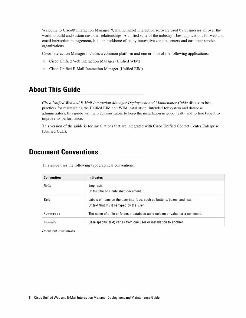
This guide uses the following typographical conventions.
Document conventions
Convention Indicates
Italic Emphasis.
Or the title of a published document.
Bold Labels of items on the user interface, such as buttons, boxes, and lists.
Or text that must be typed by the user.
Monospace The name of a file or folder, a database table column or value, or a command.
Variable User-specific text; varies from one user or installation to another.
8 Cisco Unified Web and E-Mail Interaction Manager Deployment and Maintenance Guide
Other Learning Resources
Various learning tools are available within the product, as well as on the product CD and our web site. You can also request formal end-user or technical training.
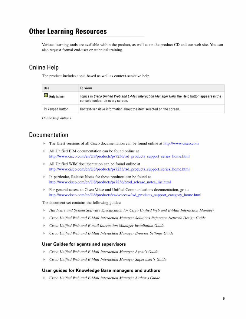
Online HelpThe product includes topic-based as well as context-sensitive help.
Online help options
Documentation The latest versions of all Cisco documentation can be found online at http://www.cisco.com
All Unified EIM documentation can be found online at http://www.cisco.com/en/US/products/ps7236/tsd_products_support_series_home.html
All Unified WIM documentation can be found online at http://www.cisco.com/en/US/products/ps7233/tsd_products_support_series_home.html
In particular, Release Notes for these products can be found at http://www.cisco.com/en/US/products/ps7236/prod_release_notes_list.html
For general access to Cisco Voice and Unified Communications documentation, go to http://www.cisco.com/en/US/products/sw/voicesw/tsd_products_support_category_home.html
The document set contains the following guides:
Hardware and System Software Specification for Cisco Unified Web and E-Mail Interaction Manager
Cisco Unified Web and E-Mail Interaction Manager Solutions Reference Network Design Guide
Cisco Unified Web and E-mail Interaction Manager Installation Guide
Cisco Unified Web and E-Mail Interaction Manager Browser Settings Guide
User Guides for agents and supervisors
Cisco Unified Web and E-Mail Interaction Manager Agent’s Guide
Cisco Unified Web and E-Mail Interaction Manager Supervisor’s Guide
User guides for Knowledge Base managers and authors
Cisco Unified Web and E-Mail Interaction Manager Author’s Guide
Use To view
Help button Topics in Cisco Unified Web and E-Mail Interaction Manager Help; the Help button appears in the console toolbar on every screen.
F1 keypad button Context-sensitive information about the item selected on the screen.
9

User guides for administrators
Cisco Unified Web and E-Mail Interaction Manager Administrator’s Guide to Administration Console
Cisco Unified Web and E-Mail Interaction Manager Administrator’s Guide to Routing and Workflows
Cisco Unified Web and E-Mail Interaction Manager Administrator’s Guide to Chat and Collaboration Resources
Cisco Unified Web and E-Mail Interaction Manager Administrator’s Guide to Email Resources
Cisco Unified Web and E-Mail Interaction Manager Administrator’s Guide to Data Adapter
Cisco Unified Web and E-Mail Interaction Manager Administrator’s Guide to Offers Console
Cisco Unified Web and E-Mail Interaction Manager Administrator’s Guide to Reports Console
Cisco Unified Web and E-Mail Interaction Manager Administrator’s Guide to System Console
Cisco Unified Web and E-Mail Interaction Manager Administrator’s Guide to Tools Console
10 Cisco Unified Web and E-Mail Interaction Manager Deployment and Maintenance Guide
Preparing Unified CCE for the Integration
Relationship Between Objects in Unified CCE and Unified EIM and WIM
Designing Your Installation
Obtaining Unified EIM and WIM Licenses
Installing Unified CCE
Setting up Agent Desktops for Voice Call Routing
Configuring Cisco Unified Communication Manager for Routing Voice Calls
Planning Unified CCE Configuration
Configuring Unified CCE
Installing Unified EIM and WIM and the Integration
Preparing Cisco Media Blender for the Integration
Configuring the System for Multiple Agent PGs
Configuring Finesse

This chapter provides an overview of the process of setting up an integrated Unified EIM and WIM–Unified CCE system. It includes a note about the relationship between objects in the two systems.
Relationship Between Objects in Unified CCE and Unified EIM and WIM
This section provides a brief introduction to the relationship or “mapping” between objects that are used in both Unified CCE and Unified EIM and WIM.
The following table provides a high-level view of the relationship between various objects.
Typically, the mapping between these objects is initially set up by running the Cisco Interaction Manager integration wizard. The integration wizard can be run once for each department. Subsequently, additional objects can be created in Unified CCE and manually mapped to Unified EIM and WIM objects. This is done from the Unified EIM and WIM Administration Console.
Properties of mapped objects are set up in Unified CCE, while permissions are managed through Unified EIM and WIM.
Designing Your Installation
See the Cisco Unified Web and E-Mail Interaction Manager Solutions Reference Network Design Guide (for Unified CCE) to evaluate available deployment models and design the installation.
Obtaining Unified EIM and WIM Licenses
To order licenses for the Unified EIM and WIM deployment, contact the Cisco License team. You will need licenses while setting up the integrated system.
Unified CCE object Mapped in Unified EIM and WIM to Notes
Agent
Supervisor
Administrator
User An agent belongs to a peripheral.
A peripheral belongs to an agent peripheral gateway (PG).
Skill group User group A skill group belongs to a peripheral.
A peripheral belongs to an agent PG.
Media routing domain (MRD)
Queue Multiple queues can belong to a single MRD.
Script selector Queue A script selector can belong to only one queue.
12 Cisco Unified Web and E-Mail Interaction Manager Deployment and Maintenance Guide
Installing Unified CCE
Ensure that Unified CCE is installed and available for use. Verify that the following items are installed:
Unified CCE Instance
Call Router Side A
Call Router Side B (optional)
Logger Side A
Logger Side B (optional)
Primary Admin Workstation
Secondary Admin Workstation (optional)
Historic Data Server
Network Interface Controllers (NIC) (Only required for Pre-routing)
Agent Peripheral Gateway (Agent PG)
Media Routing Peripheral Gateway (MR PG)
CTI Server
CUIC Database
Java Telephony Application Programming Interface (JTAPI)
Cisco Media Blender (CMB) (Only required for callback, delayed callback, and blended collaboration activities.)
Computer Telephony Integration Object Server (CTIOS) (Only required for callback, delayed callback, and blended collaboration activities.)
Cisco Finesse
See the following documents for help with installing and configuring the system:
Getting Started with Cisco Unified Contact Center Enterprise
Cisco Unified Contact Center Enterprise Installation Guide
Setting up Agent Desktops for Voice Call Routing
Install IP Communicator on each agent’s desktop, or configure an IP phone that communicates with Cisco Unified Communication Manager for the agent. Look at the following links for detailed instructions on installing and configuring IP Communicator and IP phones.
IP Communicator: http://www.cisco.com/en/US/products/sw/voicesw/ps5475/index.html
IP Phone: http://www.cisco.com/en/US/products/hw/phones/ps379/index.html
Preparing Unified CCE for the Integration 13
Configuring Cisco Unified Communication Manager for Routing Voice Calls
This section talks about how to configure phones, directory numbers, and end users from the Cisco Unified Communication Manager Administration user interface.
To configure Cisco Unified Communication Manager for routing voice calls:
1. Open a web browser and launch the URL: http://Cisco Unified Communication Manager Server Name.
2. On the page, click the link Cisco Unified Communications Manager Administration.
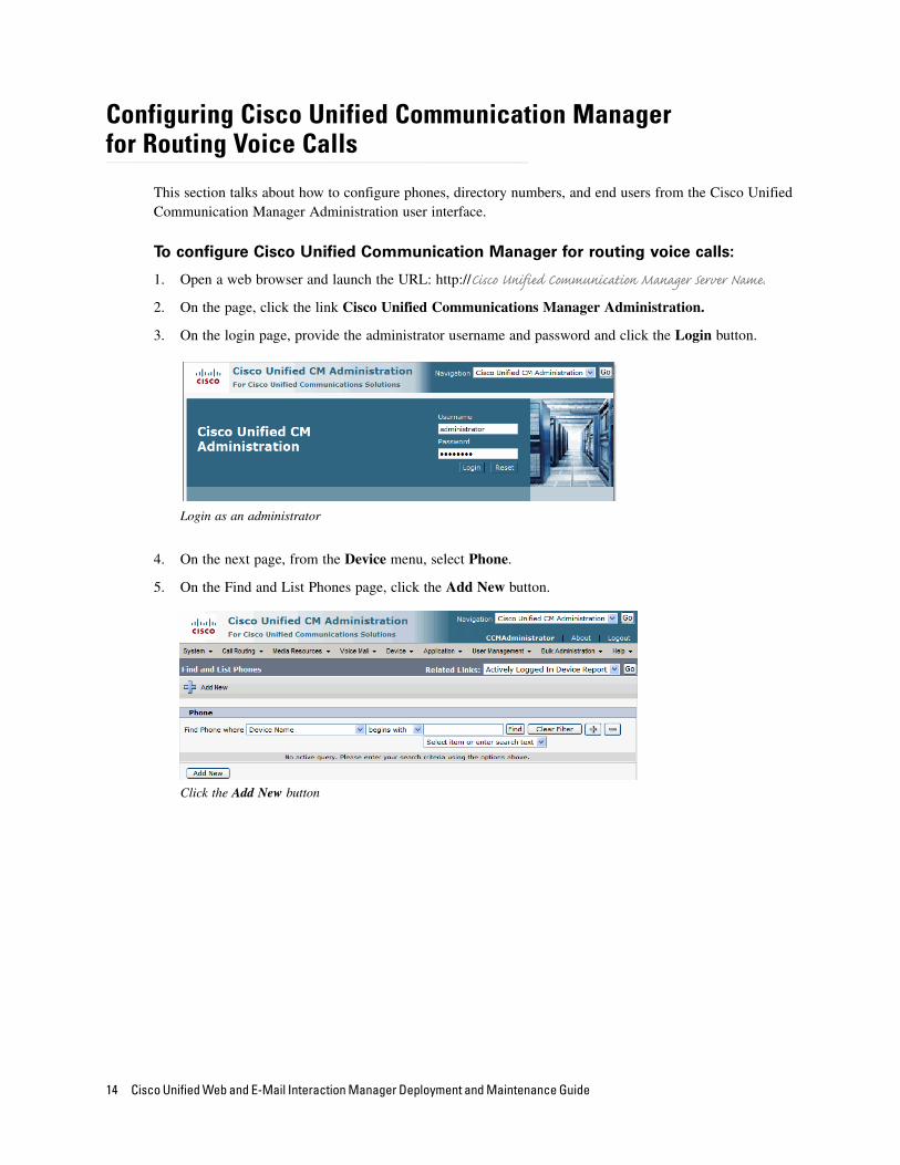
3. On the login page, provide the administrator username and password and click the Login button.
Login as an administrator
4. On the next page, from the Device menu, select Phone.
5. On the Find and List Phones page, click the Add New button.
Click the Add New button
14 Cisco Unified Web and E-Mail Interaction Manager Deployment and Maintenance Guide
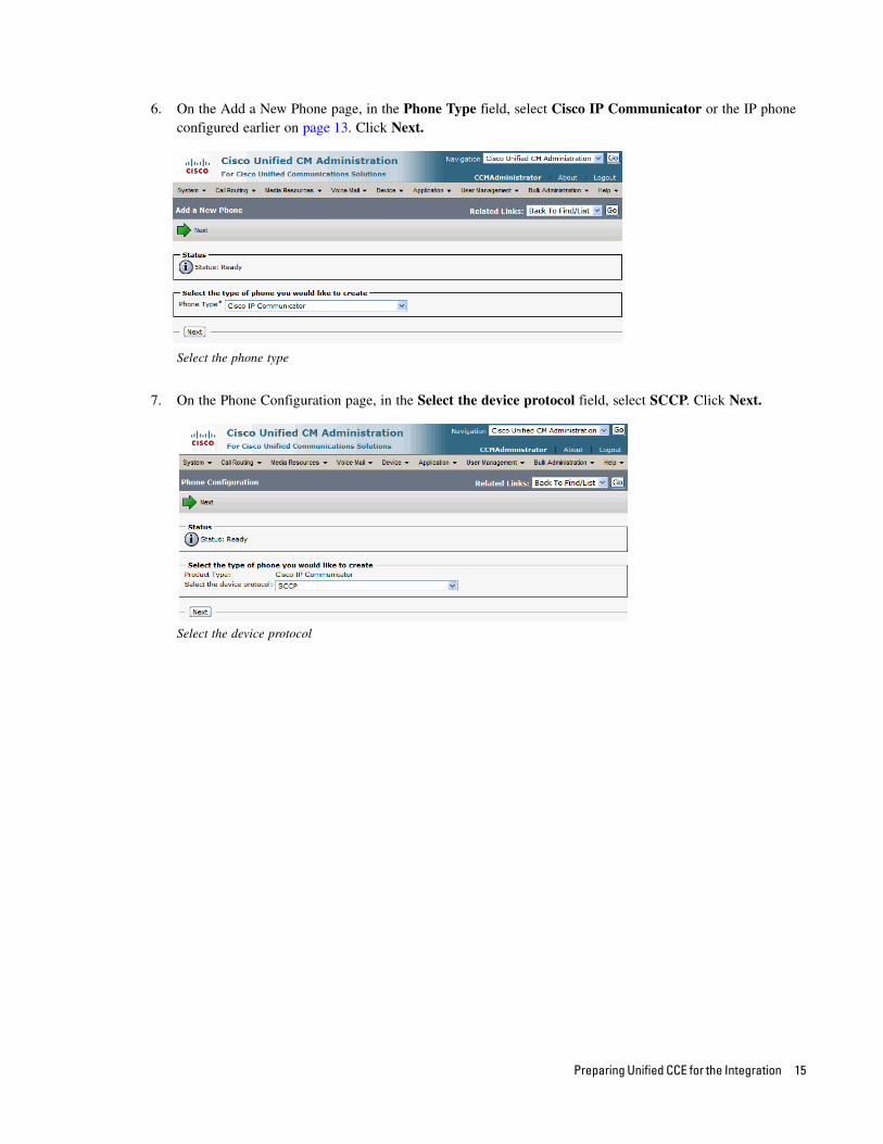
6. On the Add a New Phone page, in the Phone Type field, select Cisco IP Communicator or the IP phone configured earlier on page 13. Click Next.
Select the phone type
7. On the Phone Configuration page, in the Select the device protocol field, select SCCP. Click Next.
Select the device protocol
Preparing Unified CCE for the Integration 15

8. On the Phone Configuration page, provide the details for the new phone. Refer to Help > This Page for details about the fields. After providing all the required information, click the Save button.
Configure the phone properties
9. Next, from the Call Routing menu, select Directory Number.
10. On the Find and List Directory Numbers page, click the Add New button.
Click the Add New button
16 Cisco Unified Web and E-Mail Interaction Manager Deployment and Maintenance Guide
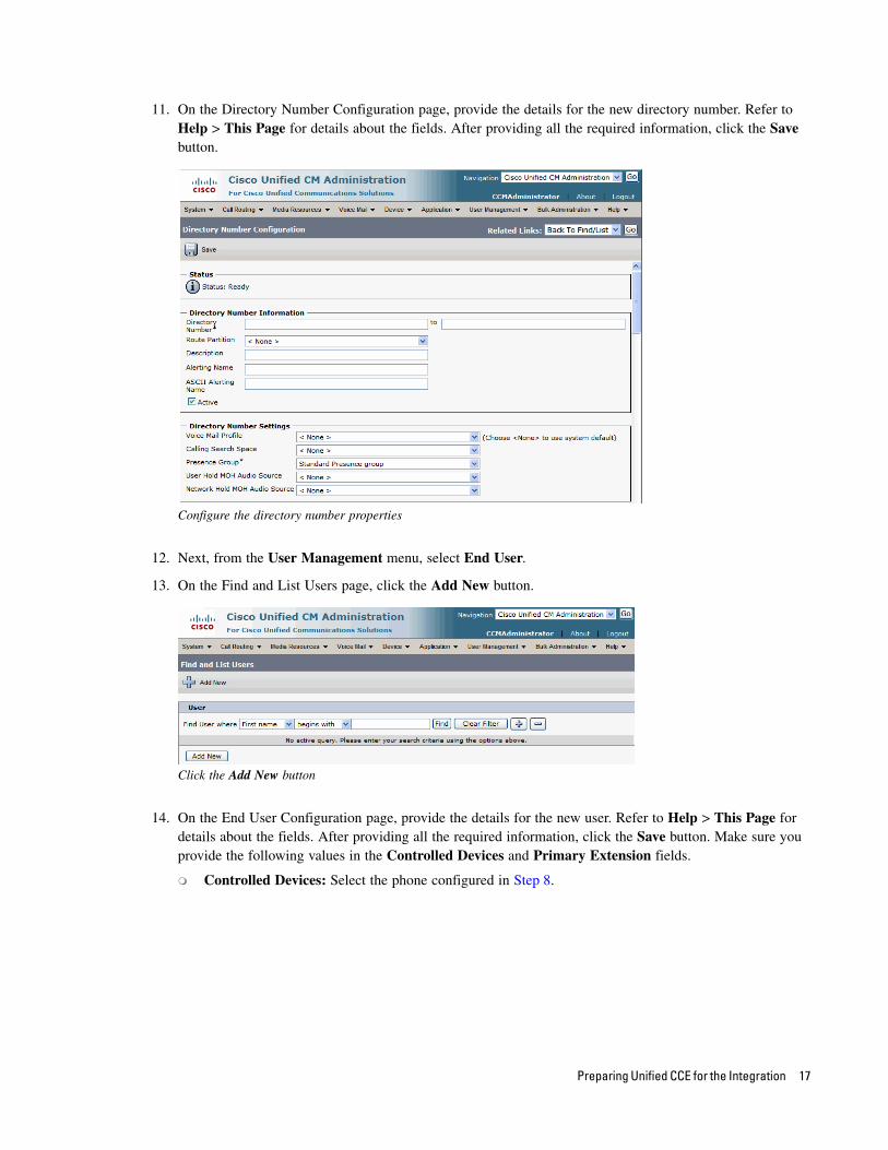
11. On the Directory Number Configuration page, provide the details for the new directory number. Refer to Help > This Page for details about the fields. After providing all the required information, click the Save button.
Configure the directory number properties
12. Next, from the User Management menu, select End User.
13. On the Find and List Users page, click the Add New button.
Click the Add New button
14. On the End User Configuration page, provide the details for the new user. Refer to Help > This Page for details about the fields. After providing all the required information, click the Save button. Make sure you provide the following values in the Controlled Devices and Primary Extension fields.
Controlled Devices: Select the phone configured in Step 8.
Preparing Unified CCE for the Integration 17
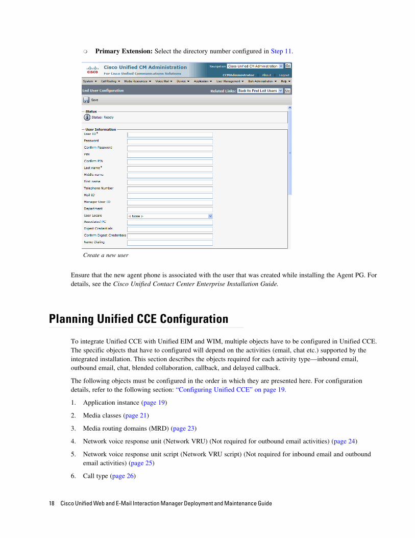
Primary Extension: Select the directory number configured in Step 11.
Create a new user
Ensure that the new agent phone is associated with the user that was created while installing the Agent PG. For details, see the Cisco Unified Contact Center Enterprise Installation Guide.
Planning Unified CCE Configuration
To integrate Unified CCE with Unified EIM and WIM, multiple objects have to be configured in Unified CCE. The specific objects that have to configured will depend on the activities (email, chat etc.) supported by the integrated installation. This section describes the objects required for each activity type—inbound email, outbound email, chat, blended collaboration, callback, and delayed callback.
The following objects must be configured in the order in which they are presented here. For configuration details, refer to the following section: “Configuring Unified CCE” on page 19.
1. Application instance (page 19)
2. Media classes (page 21)
3. Media routing domains (MRD) (page 23)
4. Network voice response unit (Network VRU) (Not required for outbound email activities) (page 24)
5. Network voice response unit script (Network VRU script) (Not required for inbound email and outbound email activities) (page 25)
6. Call type (page 26)
18 Cisco Unified Web and E-Mail Interaction Manager Deployment and Maintenance Guide
7. Media routing peripheral gateway (MR PG) (page 27)
8. Agent desk settings (page 31)
9. Agent peripheral gateway (Agent PG) (page 32)
10. Network trunk group (page 34)
11. Application path (page 35)
12. Agents (page 37)
13. Skill Groups
IPTA skill groups (page 39)
Non-IPTA skill group (Not required for blended collaboration, callback, and delayed callback activities.) (page 40)
14. Labels (Not required for callback and delayed callback activities.) (page 42)
15. Script selector (page 43)
16. Scripts (Not required for outbound email activities) (page 45)
17. Device target (Not required for inbound email, outbound email, and chat activities) (page 50)
18. Expanded Call Context (ECC) variables (page 51)
19. Cisco Finesse (page 58)
Configuring Unified CCE
This section describes the process of configuring Unified CCE objects that are required for the integration with Unified EIM and WIM. These objects must be configured in the order in which they are presented here. For details of these objects refer to the Online Help and printed documentation for Unified CCE.
Configuring Application InstanceApplication instances are configured for each installation of a multi-media feature in the configuration.
Configure a single application instance for integrating with Unified EIM and WIM. This application instance is used for inbound email, outbound email, chat, blended collaboration, callback, and delayed callback activities.
To configure an application instance:
1. Go to Start > All Programs > ICM Admin Workstation > Configuration Manager.
2. In the Configuration Manager window, browse to Tools > List Tools > Application Instance List.
3. Double-click Application Instance List.
4. In the Application Instance List window, in the Select filter data section, click Retrieve. Then, in the Application Instance section, click Add.
A new entry is created in the Application Instance section and the Attributes tab becomes editable.
5. On the Attributes tab, provide the following details:
Preparing Unified CCE for the Integration 19
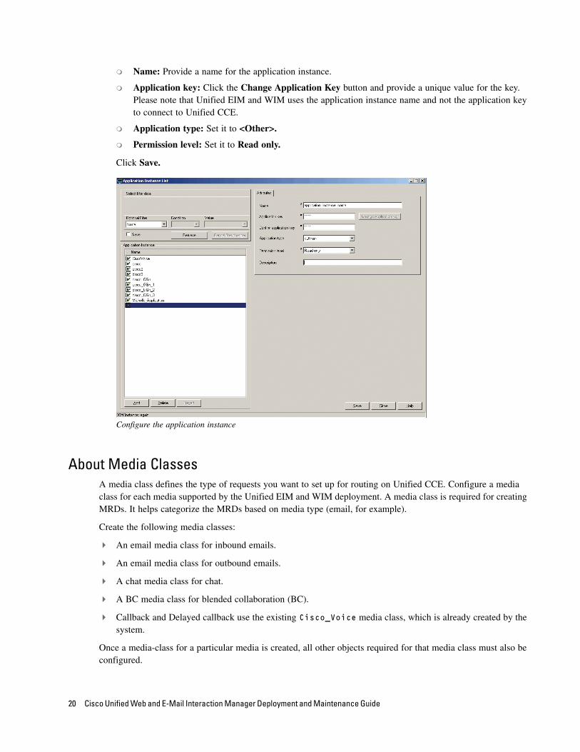
Name: Provide a name for the application instance.
Application key: Click the Change Application Key button and provide a unique value for the key. Please note that Unified EIM and WIM uses the application instance name and not the application key to connect to Unified CCE.
Application type: Set it to <Other>.
Permission level: Set it to Read only.
Click Save.
Configure the application instance
About Media ClassesA media class defines the type of requests you want to set up for routing on Unified CCE. Configure a media class for each media supported by the Unified EIM and WIM deployment. A media class is required for creating MRDs. It helps categorize the MRDs based on media type (email, for example).
Create the following media classes:
An email media class for inbound emails.
An email media class for outbound emails.
A chat media class for chat.
A BC media class for blended collaboration (BC).
Callback and Delayed callback use the existing Cisco_Voice media class, which is already created by the system.
Once a media-class for a particular media is created, all other objects required for that media class must also be configured.
20 Cisco Unified Web and E-Mail Interaction Manager Deployment and Maintenance Guide
Important Note About Media ClassesIf the deployment does not require one or more of these media classes, Blended Collaboration, for example, and the administrator does not wish to create it or its associated objects, complete the following steps before starting the application:
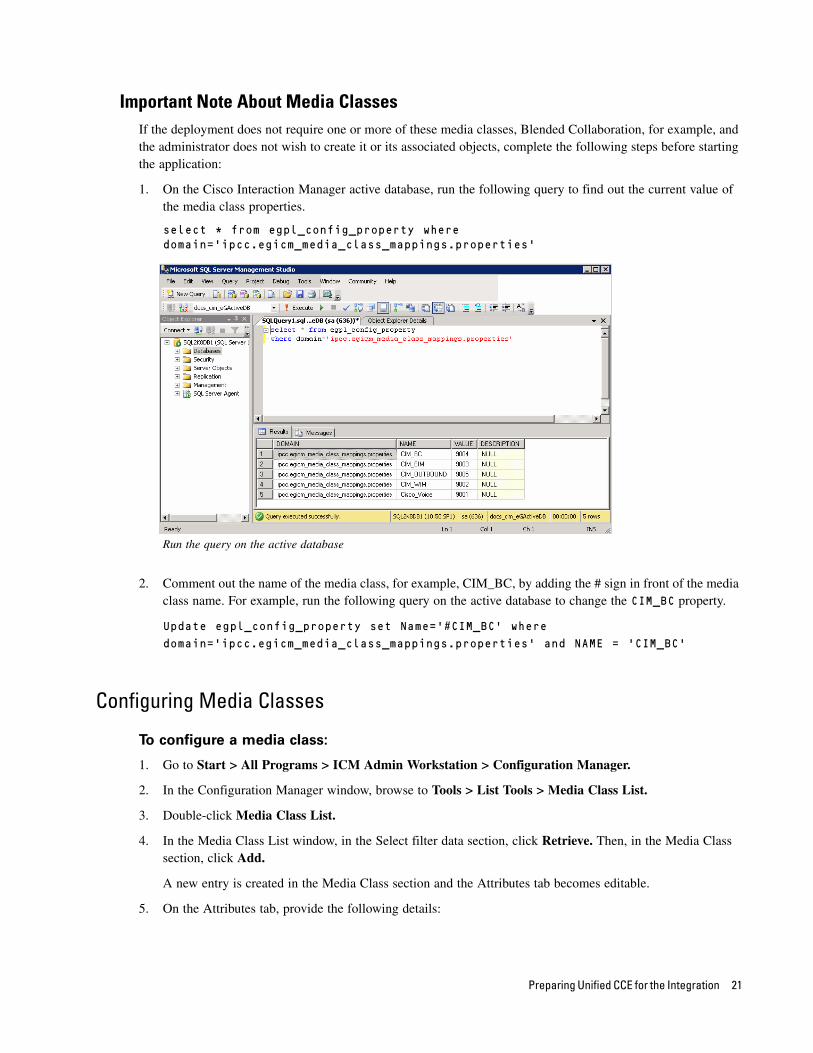
1. On the Cisco Interaction Manager active database, run the following query to find out the current value of the media class properties.
select * from egpl_config_property where domain='ipcc.egicm_media_class_mappings.properties'
Run the query on the active database
2. Comment out the name of the media class, for example, CIM_BC, by adding the # sign in front of the media class name. For example, run the following query on the active database to change the CIM_BC property.
Update egpl_config_property set Name='#CIM_BC' where
domain='ipcc.egicm_media_class_mappings.properties' and NAME = 'CIM_BC'
Configuring Media Classes
To configure a media class:
1. Go to Start > All Programs > ICM Admin Workstation > Configuration Manager.
2. In the Configuration Manager window, browse to Tools > List Tools > Media Class List.
3. Double-click Media Class List.
4. In the Media Class List window, in the Select filter data section, click Retrieve. Then, in the Media Class section, click Add.
A new entry is created in the Media Class section and the Attributes tab becomes editable.
5. On the Attributes tab, provide the following details:
Preparing Unified CCE for the Integration 21

Name: Provide a name for the media class. If the media class is meant to be used in Unified EIM and WIM, use one of the following names. Note that the names of media classes are case sensitive. Make sure that you use the exact names as provided here.
CIM_EIM (for inbound email)
CIM_OUTBOUND (for outbound email)
CIM_WIM (for chat)
CIM_BC (for blended collaboration)
Media classes are set in the active database table egpl_config_property table as CIM_EIM, CIM_OUTBOUND, CIM_WIM, and CIM_BC. If you use names other than these, you must change them in the database and then restart the Cisco Service. Note that the names of media classes are case sensitive.
In the Task section, set the following.
Life: Set the value to 300 seconds.
Start timeout: Set the value to 30 seconds.
Max Duration: Set the value to 28800 seconds.
6. Click Save.
Configure media classes
22 Cisco Unified Web and E-Mail Interaction Manager Deployment and Maintenance Guide

Configuring Media Routing Domains (MRDs)An MRD is a collection of skill groups and services that are associated with a common communication medium. Unified CCE uses an MRD to route tasks to agents who are associated with a skill group and a particular medium. A media routing domain is created in Unified CCE for mapping to queues in Unified EIM and WIM.
Create the following media routing domains:
For inbound email media class, create an email media routing domain.
For outbound email media class, create an email media routing domain.
For chat, create a chat media routing domain.
For blended collaboration, create a BC media routing domain.
For callback and delayed callback, use the existing voice media routing domain (Cisco_Voice) created by the system.
To configure a media routing domain:
1. Go to Start > All Programs > ICM Admin Workstation > Configuration Manager.
2. In the Configuration Manager window, browse to Tools > List Tools > Media Routing Domain List.
3. Double-click Media Routing Domain List.
4. In the Media Routing Domain List window, in the Select filter data section, click Retrieve. Then, in the Media Routing Domain section, click Add.
A new entry is created and the Attributes tab becomes editable.
5. On the Attributes tab, provide the following details:
Name: Provide a name for the media routing domain.
Media class: Select a media class created for Cisco Unified Web and E-Mail Interaction Manager (page 21). Make sure that you select the correct media class for the MRD. For example:
For inbound email MRD, select the CIM_EIM media class.
For outbound email MRD, the CIM_OUTBOUND media class.
For chat MRD, select the CIM_WIM media class.
For blended collaboration MRD, select the CIM_BC media class.
Interruptible: Select this option while creating MRDs for inbound and outbound emails.
In the Calls in Queue section, set the following:
Max: Defines the maximum number of activities to be queued for the MRD. The recommended value for this setting is 5000. However, the maximum value for email activities can be set to 15000. For all other activities, this value should not be set more than 5000. If the field is left blank, Unified EIM and WIM will read the value from the active database table egpl_config_property. By default the value of the DEFAULT_MAX_CALLS_IN_MRD property is set to 5000.
6. Click Save.
Preparing Unified CCE for the Integration 23
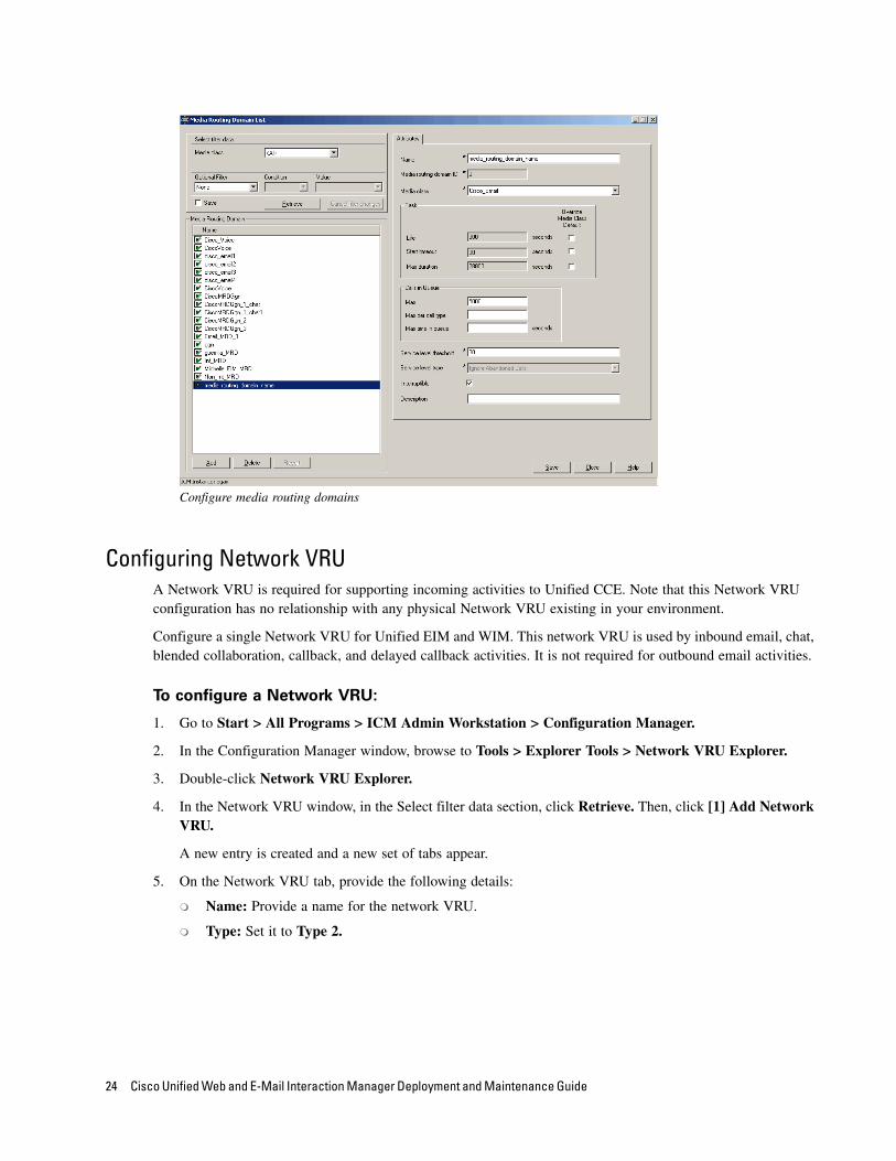
Configure media routing domains
Configuring Network VRUA Network VRU is required for supporting incoming activities to Unified CCE. Note that this Network VRU configuration has no relationship with any physical Network VRU existing in your environment.
Configure a single Network VRU for Unified EIM and WIM. This network VRU is used by inbound email, chat, blended collaboration, callback, and delayed callback activities. It is not required for outbound email activities.
To configure a Network VRU:
1. Go to Start > All Programs > ICM Admin Workstation > Configuration Manager.
2. In the Configuration Manager window, browse to Tools > Explorer Tools > Network VRU Explorer.
3. Double-click Network VRU Explorer.
4. In the Network VRU window, in the Select filter data section, click Retrieve. Then, click [1] Add Network VRU.
A new entry is created and a new set of tabs appear.
5. On the Network VRU tab, provide the following details:
Name: Provide a name for the network VRU.
Type: Set it to Type 2.
24 Cisco Unified Web and E-Mail Interaction Manager Deployment and Maintenance Guide
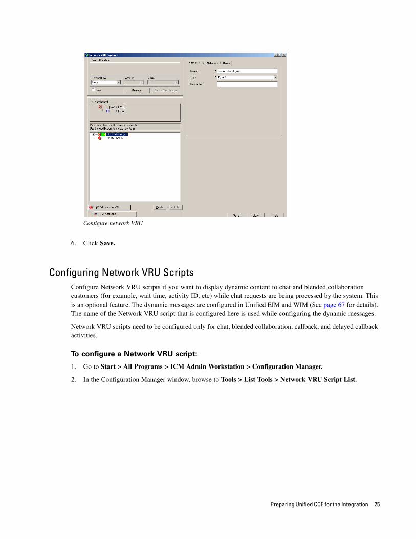
Configure network VRU
6. Click Save.
Configuring Network VRU ScriptsConfigure Network VRU scripts if you want to display dynamic content to chat and blended collaboration customers (for example, wait time, activity ID, etc) while chat requests are being processed by the system. This is an optional feature. The dynamic messages are configured in Unified EIM and WIM (See page 67 for details). The name of the Network VRU script that is configured here is used while configuring the dynamic messages.
Network VRU scripts need to be configured only for chat, blended collaboration, callback, and delayed callback activities.
To configure a Network VRU script:
1. Go to Start > All Programs > ICM Admin Workstation > Configuration Manager.
2. In the Configuration Manager window, browse to Tools > List Tools > Network VRU Script List.
Preparing Unified CCE for the Integration 25

3. In the Network VRU Script List window, create a script and select the Network VRU created for Unified WIM and EIM (page 24).
Create a Network VRU script
4. Click the Save button.
Configuring Call TypesA call type is required to categorize a dialed number (for voice) or a script selector (for email). Call types are used in configuring routing scripts.
Individual call types are required for the following activities: inbound email, outbound email, chat, blended collaboration, callback, and delayed callback activities. Make sure you complete these steps for each type of activity.
To configure a call type:
1. Go to Start > All Programs > ICM Admin Workstation > Configuration Manager.
2. In the Configuration Manager window, browse to Tools > List Tools > Call Type List.
3. Double-click Call Type List.
4. In the Call Type List window, in the Select filter data section, click Retrieve. Then, in the Call Type section, click Add.
A new entry is created and the Attributes tab becomes editable.
5. On the Attributes tab, in the Name field, provide a name for the call type. Click Save.
26 Cisco Unified Web and E-Mail Interaction Manager Deployment and Maintenance Guide
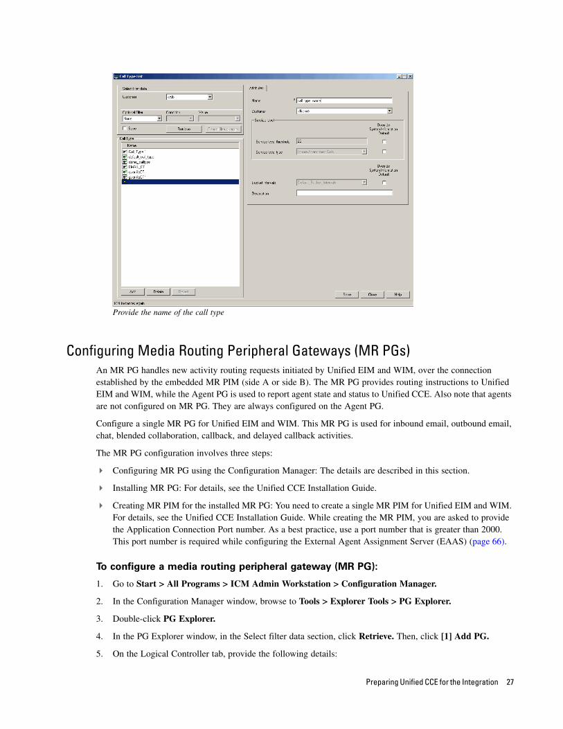
Provide the name of the call type
Configuring Media Routing Peripheral Gateways (MR PGs)An MR PG handles new activity routing requests initiated by Unified EIM and WIM, over the connection established by the embedded MR PIM (side A or side B). The MR PG provides routing instructions to Unified EIM and WIM, while the Agent PG is used to report agent state and status to Unified CCE. Also note that agents are not configured on MR PG. They are always configured on the Agent PG.
Configure a single MR PG for Unified EIM and WIM. This MR PG is used for inbound email, outbound email, chat, blended collaboration, callback, and delayed callback activities.
The MR PG configuration involves three steps:
Configuring MR PG using the Configuration Manager: The details are described in this section.
Installing MR PG: For details, see the Unified CCE Installation Guide.
Creating MR PIM for the installed MR PG: You need to create a single MR PIM for Unified EIM and WIM. For details, see the Unified CCE Installation Guide. While creating the MR PIM, you are asked to provide the Application Connection Port number. As a best practice, use a port number that is greater than 2000. This port number is required while configuring the External Agent Assignment Server (EAAS) (page 66).
To configure a media routing peripheral gateway (MR PG):
1. Go to Start > All Programs > ICM Admin Workstation > Configuration Manager.
2. In the Configuration Manager window, browse to Tools > Explorer Tools > PG Explorer.
3. Double-click PG Explorer.
4. In the PG Explorer window, in the Select filter data section, click Retrieve. Then, click [1] Add PG.
5. On the Logical Controller tab, provide the following details:
Preparing Unified CCE for the Integration 27
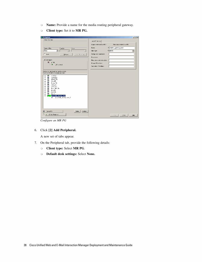
Name: Provide a name for the media routing peripheral gateway.
Client type: Set it to MR PG.
Configure an MR PG
6. Click [2] Add Peripheral.
A new set of tabs appear.
7. On the Peripheral tab, provide the following details:
Client type: Select MR PG.
Default desk settings: Select None.
28 Cisco Unified Web and E-Mail Interaction Manager Deployment and Maintenance Guide
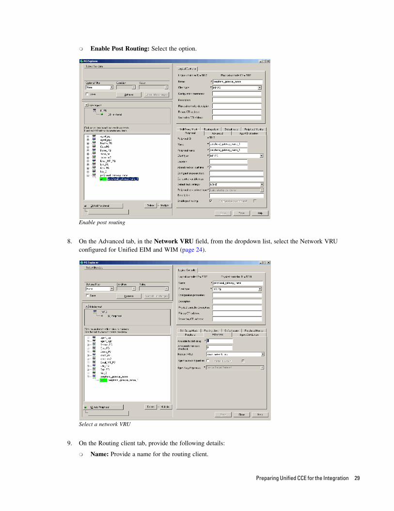
Enable Post Routing: Select the option.
Enable post routing
8. On the Advanced tab, in the Network VRU field, from the dropdown list, select the Network VRU configured for Unified EIM and WIM (page 24).
Select a network VRU
9. On the Routing client tab, provide the following details:
Name: Provide a name for the routing client.
Preparing Unified CCE for the Integration 29
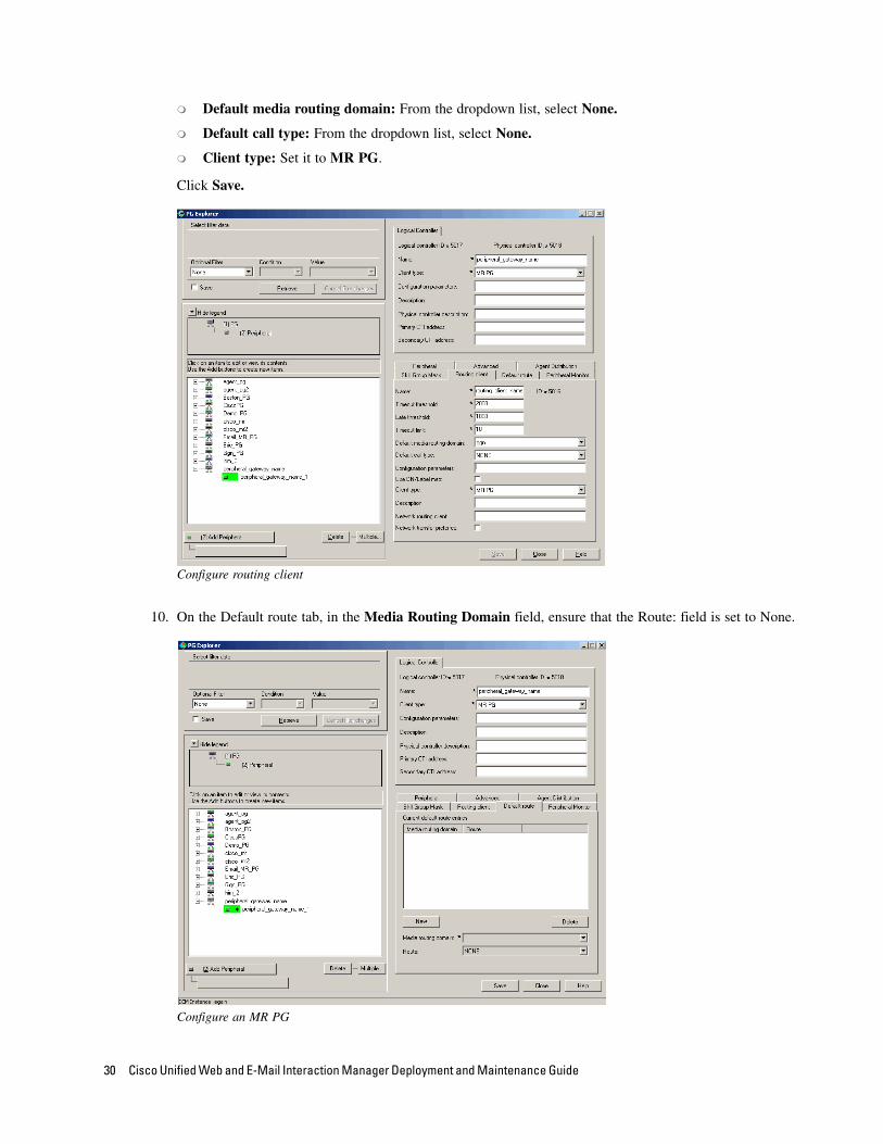
Default media routing domain: From the dropdown list, select None.
Default call type: From the dropdown list, select None.
Client type: Set it to MR PG.
Click Save.
Configure routing client
10. On the Default route tab, in the Media Routing Domain field, ensure that the Route: field is set to None.
Configure an MR PG
30 Cisco Unified Web and E-Mail Interaction Manager Deployment and Maintenance Guide
11. Click Save. Note down the Logical controller ID generated in the Logical Controller tab. It is needed while configuring MR PIM.
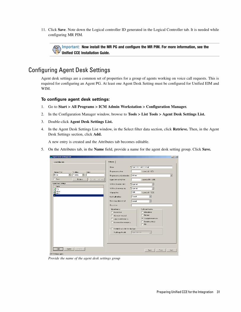
Configuring Agent Desk SettingsAgent desk settings are a common set of properties for a group of agents working on voice call requests. This is required for configuring an Agent PG. At least one Agent Desk Setting must be configured for Unified EIM and WIM.
To configure agent desk settings:
1. Go to Start > All Programs > ICM Admin Workstation > Configuration Manager.
2. In the Configuration Manager window, browse to Tools > List Tools > Agent Desk Settings List.
3. Double-click Agent Desk Settings List.
4. In the Agent Desk Settings List window, in the Select filter data section, click Retrieve. Then, in the Agent Desk Settings section, click Add.
A new entry is created and the Attributes tab becomes editable.
5. On the Attributes tab, in the Name field, provide a name for the agent desk setting group. Click Save.
Provide the name of the agent desk settings group
Important: Now install the MR PG and configure the MR PIM. For more information, see the
Unified CCE Installation Guide.
Preparing Unified CCE for the Integration 31
Configuring Agent Peripheral Gateway (Agent PG)An Agent PG is required for creating one or more peripherals that manage agent distribution within Unified CCE. Configure an Agent PG using the Configuration Manager and then install it on the appropriate machine.
You can configure a maximum of four Agent PGs for Unified EIM and WIM. These Agent PGs are used for inbound email, outbound email, chat, blended collaboration, callback, and delayed callback activities.
Note that you can also use an existing Agent PG if it is of the type Call Manger/Soft ACD.
To configure an agent peripheral gateway:
1. Go to Start > All Programs > ICM Admin Workstation > Configuration Manager.
2. In the Configuration Manager window, browse to Tools > Explorer Tools > PG Explorer.
3. Double-click PG Explorer.
4. In the PG Explorer window, in the Select filter data section, click Retrieve. Then, click [1] Add PG.
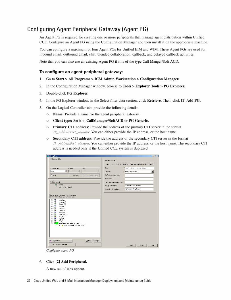
5. On the Logical Controller tab, provide the following details:
Name: Provide a name for the agent peripheral gateway.
Client type: Set it to CallManager/SoftACD or PG Generic.
Primary CTI address: Provide the address of the primary CTI server in the format IP_Address:Port_Number. You can either provide the IP address, or the host name.
Secondary CTI address: Provide the address of the secondary CTI server in the format IP_Address:Port_Number. You can either provide the IP address, or the host name. The secondary CTI address is needed only if the Unified CCE system is duplexed.
Configure agent PG
6. Click [2] Add Peripheral.
A new set of tabs appear.
32 Cisco Unified Web and E-Mail Interaction Manager Deployment and Maintenance Guide

7. On the Peripheral tab, do the following:
Default desk settings: From the dropdown list, select the agent desk settings configured for Unified EIM and WIM (page 31).
Enable post routing: Select the option.
Select agent desk settings
8. On the Routing client tab, in the Name field, provide a name for the routing client.
9. On the Agent Distribution tab, do the following:
a. Click New.
b. Select the Enable agent reporting option.
c. Select the Agent event detail option.
d. In the Currently Selected Site section, set the following:
Distributor site name: Provide the host name of the machine where distributor is installed.
Enable: Select the option.
Preparing Unified CCE for the Integration 33
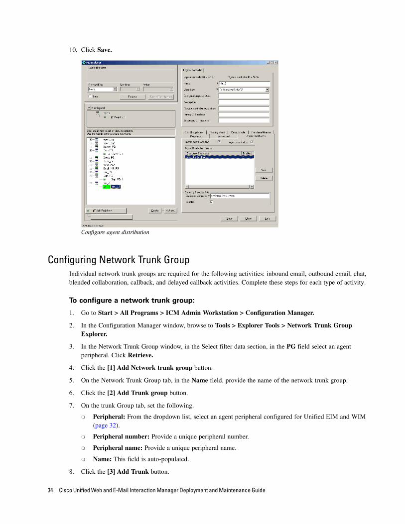
10. Click Save.
Configure agent distribution
Configuring Network Trunk GroupIndividual network trunk groups are required for the following activities: inbound email, outbound email, chat, blended collaboration, callback, and delayed callback activities. Complete these steps for each type of activity.
To configure a network trunk group:
1. Go to Start > All Programs > ICM Admin Workstation > Configuration Manager.
2. In the Configuration Manager window, browse to Tools > Explorer Tools > Network Trunk Group Explorer.
3. In the Network Trunk Group window, in the Select filter data section, in the PG field select an agent peripheral. Click Retrieve.
4. Click the [1] Add Network trunk group button.
5. On the Network Trunk Group tab, in the Name field, provide the name of the network trunk group.
6. Click the [2] Add Trunk group button.
7. On the trunk Group tab, set the following.
Peripheral: From the dropdown list, select an agent peripheral configured for Unified EIM and WIM (page 32).
Peripheral number: Provide a unique peripheral number.
Peripheral name: Provide a unique peripheral name.
Name: This field is auto-populated.
8. Click the [3] Add Trunk button.
34 Cisco Unified Web and E-Mail Interaction Manager Deployment and Maintenance Guide
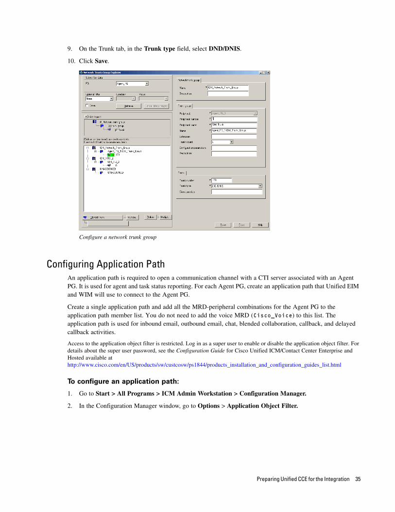
9. On the Trunk tab, in the Trunk type field, select DND/DNIS.
10. Click Save.
Configure a network trunk group
Configuring Application PathAn application path is required to open a communication channel with a CTI server associated with an Agent PG. It is used for agent and task status reporting. For each Agent PG, create an application path that Unified EIM and WIM will use to connect to the Agent PG.
Create a single application path and add all the MRD-peripheral combinations for the Agent PG to the application path member list. You do not need to add the voice MRD (Cisco_Voice) to this list. The application path is used for inbound email, outbound email, chat, blended collaboration, callback, and delayed callback activities.
Access to the application object filter is restricted. Log in as a super user to enable or disable the application object filter. For details about the super user password, see the Configuration Guide for Cisco Unified ICM/Contact Center Enterprise and Hosted available at http://www.cisco.com/en/US/products/sw/custcosw/ps1844/products_installation_and_configuration_guides_list.html
To configure an application path:
1. Go to Start > All Programs > ICM Admin Workstation > Configuration Manager.
2. In the Configuration Manager window, go to Options > Application Object Filter.
Preparing Unified CCE for the Integration 35
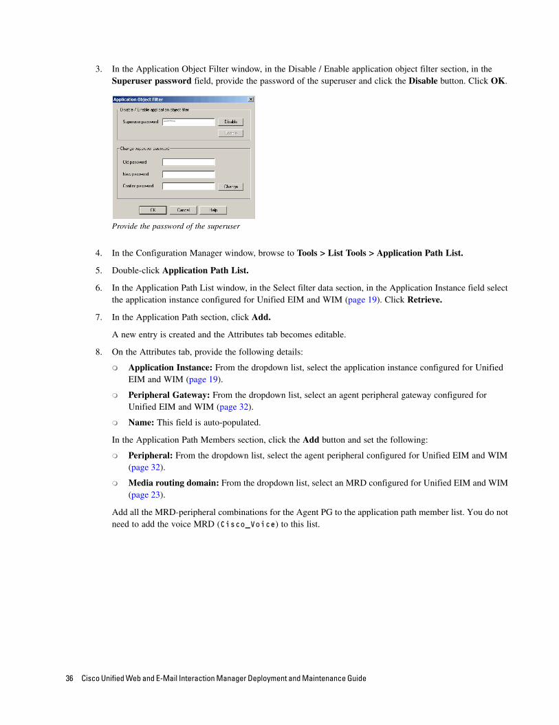
3. In the Application Object Filter window, in the Disable / Enable application object filter section, in the Superuser password field, provide the password of the superuser and click the Disable button. Click OK.
Provide the password of the superuser
4. In the Configuration Manager window, browse to Tools > List Tools > Application Path List.
5. Double-click Application Path List.
6. In the Application Path List window, in the Select filter data section, in the Application Instance field select the application instance configured for Unified EIM and WIM (page 19). Click Retrieve.
7. In the Application Path section, click Add.
A new entry is created and the Attributes tab becomes editable.
8. On the Attributes tab, provide the following details:
Application Instance: From the dropdown list, select the application instance configured for Unified EIM and WIM (page 19).
Peripheral Gateway: From the dropdown list, select an agent peripheral gateway configured for Unified EIM and WIM (page 32).
Name: This field is auto-populated.
In the Application Path Members section, click the Add button and set the following:
Peripheral: From the dropdown list, select the agent peripheral configured for Unified EIM and WIM (page 32).
Media routing domain: From the dropdown list, select an MRD configured for Unified EIM and WIM (page 23).
Add all the MRD-peripheral combinations for the Agent PG to the application path member list. You do not need to add the voice MRD (Cisco_Voice) to this list.
36 Cisco Unified Web and E-Mail Interaction Manager Deployment and Maintenance Guide
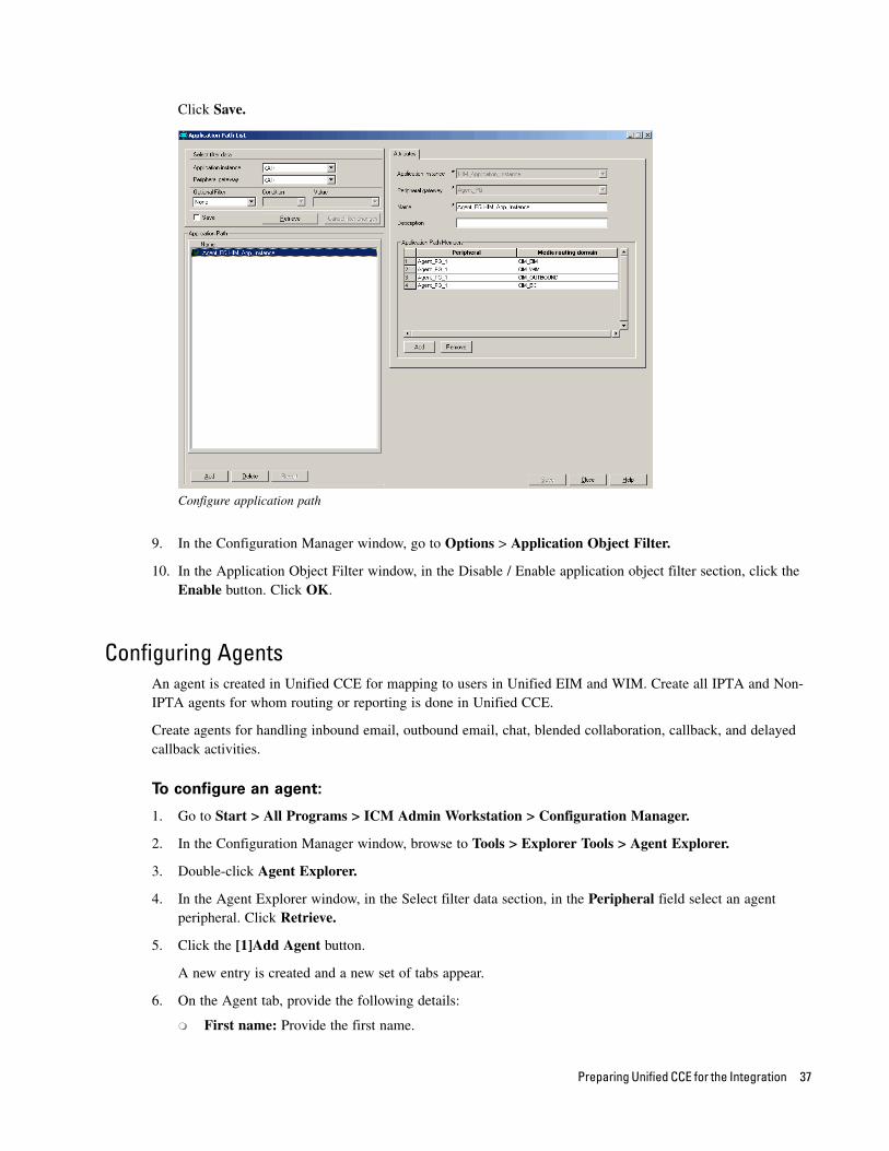
Click Save.
Configure application path
9. In the Configuration Manager window, go to Options > Application Object Filter.
10. In the Application Object Filter window, in the Disable / Enable application object filter section, click the Enable button. Click OK.
Configuring AgentsAn agent is created in Unified CCE for mapping to users in Unified EIM and WIM. Create all IPTA and Non-IPTA agents for whom routing or reporting is done in Unified CCE.
Create agents for handling inbound email, outbound email, chat, blended collaboration, callback, and delayed callback activities.
To configure an agent:
1. Go to Start > All Programs > ICM Admin Workstation > Configuration Manager.
2. In the Configuration Manager window, browse to Tools > Explorer Tools > Agent Explorer.
3. Double-click Agent Explorer.
4. In the Agent Explorer window, in the Select filter data section, in the Peripheral field select an agent peripheral. Click Retrieve.
5. Click the [1]Add Agent button.
A new entry is created and a new set of tabs appear.
6. On the Agent tab, provide the following details:
First name: Provide the first name.
Preparing Unified CCE for the Integration 37
Last name: Provide the last name.
Login name: Provide the login name for the agent. For blended collaboration, callback, and delayed callback agents, the login name should match the User ID provided while configuring End users from the Cisco Unified Communication Manager Administration user interface (page 17).
Login enabled: Select the option.
Password: Provide the password for the agent.
Enterprise name: This field is auto-populated.
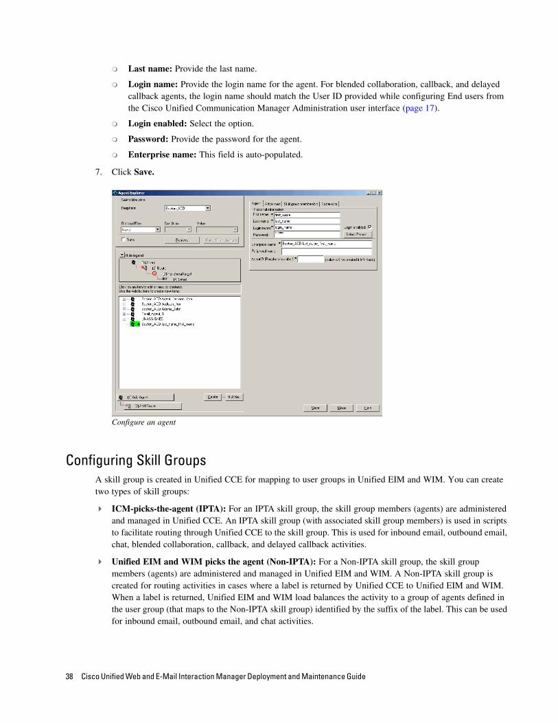
7. Click Save.
Configure an agent
Configuring Skill GroupsA skill group is created in Unified CCE for mapping to user groups in Unified EIM and WIM. You can create two types of skill groups:
ICM-picks-the-agent (IPTA): For an IPTA skill group, the skill group members (agents) are administered and managed in Unified CCE. An IPTA skill group (with associated skill group members) is used in scripts to facilitate routing through Unified CCE to the skill group. This is used for inbound email, outbound email, chat, blended collaboration, callback, and delayed callback activities.
Unified EIM and WIM picks the agent (Non-IPTA): For a Non-IPTA skill group, the skill group members (agents) are administered and managed in Unified EIM and WIM. A Non-IPTA skill group is created for routing activities in cases where a label is returned by Unified CCE to Unified EIM and WIM. When a label is returned, Unified EIM and WIM load balances the activity to a group of agents defined in the user group (that maps to the Non-IPTA skill group) identified by the suffix of the label. This can be used for inbound email, outbound email, and chat activities.
38 Cisco Unified Web and E-Mail Interaction Manager Deployment and Maintenance Guide

To configure an IPTA skill group:
1. Go to Start > All Programs > ICM Admin Workstation > Configuration Manager.
2. In the Configuration Manager window, browse to Tools > Explorer Tools > Skill Group Explorer.
3. Double-click Skill Group Explorer.
4. In the Skill Group Explorer window, in the Select filter data section, select an agent peripheral. Click Retrieve.
5. Click the [1]Add Skill group button.
A new entry is created and a new set of tabs appear.
6. On the Skill Group tab, provide the following details:
Media routing domain: From the dropdown list, select an MRD configured for Unified EIM and WIM (page 23).
Peripheral number: Provide a unique peripheral number.
Peripheral name: Provide a name for the skill group.
Name: This field is auto-populated.
ICM picks the agent: Select the option.
Configure the properties of an IPTA skill group
7. On the Skill Group Members tab, do the following:
a. Click the Add button.
Important: Users can only belong to either IPTA or Non-IPTA skill groups. Ensure that the
same user is not added to an IPTA and a Non-IPTA skill group.
Preparing Unified CCE for the Integration 39
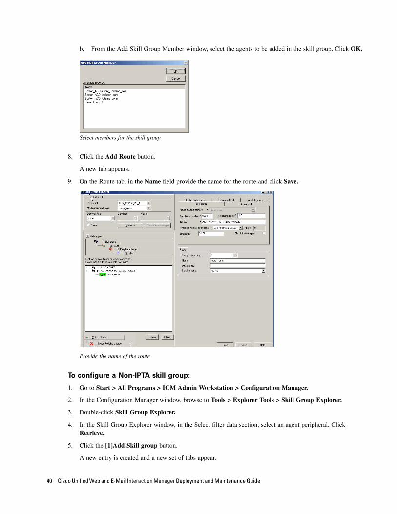
b. From the Add Skill Group Member window, select the agents to be added in the skill group. Click OK.
Select members for the skill group
8. Click the Add Route button.
A new tab appears.
9. On the Route tab, in the Name field provide the name for the route and click Save.
Provide the name of the route
To configure a Non-IPTA skill group:
1. Go to Start > All Programs > ICM Admin Workstation > Configuration Manager.
2. In the Configuration Manager window, browse to Tools > Explorer Tools > Skill Group Explorer.
3. Double-click Skill Group Explorer.
4. In the Skill Group Explorer window, in the Select filter data section, select an agent peripheral. Click Retrieve.
5. Click the [1]Add Skill group button.
A new entry is created and a new set of tabs appear.
40 Cisco Unified Web and E-Mail Interaction Manager Deployment and Maintenance Guide
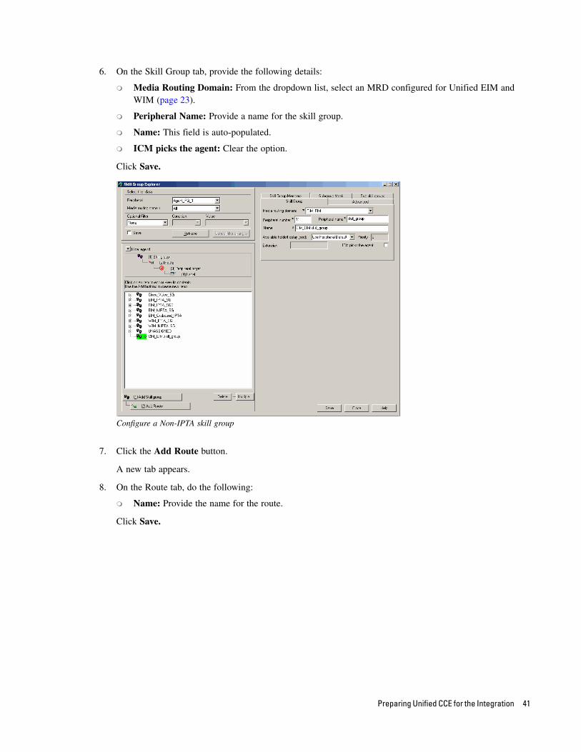
6. On the Skill Group tab, provide the following details:
Media Routing Domain: From the dropdown list, select an MRD configured for Unified EIM and WIM (page 23).
Peripheral Name: Provide a name for the skill group.
Name: This field is auto-populated.
ICM picks the agent: Clear the option.
Click Save.
Configure a Non-IPTA skill group
7. Click the Add Route button.
A new tab appears.
8. On the Route tab, do the following:
Name: Provide the name for the route.
Click Save.
Preparing Unified CCE for the Integration 41

Provide the name of the route
Configuring LabelsLabels are used by Unified EIM and WIM for Non-IPTA routing. When Unified CCE is unable to identify an agent for assigning an activity, it returns a label to Unified EIM and WIM. When a label is returned, Unified EIM and WIM load balances the activity to a group of agents defined in the user group (that maps to the Non-IPTA skill group) identified by the suffix of the label.
Configure labels for inbound email, outbound email, chat, and blended collaboration activities.
To configure a label:
1. Go to Start > All Programs > ICM Admin Workstation > Configuration Manager.
1. In the Configuration Manager window, browse to Tools > List Tools > Label List.
2. Double-click Label List.
3. In the Label List window, in the Select filter data section, in the Routing client field select the routing client configured for MR PG (page 29). Click Retrieve.
4. In the Label section, click Add.
A new entry is created and the Attributes tab becomes editable.
5. On the Attributes tab, provide the following details:
Routing client: From the dropdown list, select the routing client configured for the MR PG in step 9 in “Configuring Media Routing Peripheral Gateways (MR PGs)” on page 27.
Important: The LABEL must be configured in the following format: LBL_Enterprise_Name_of_Non-
IPTA_Skill_Group. The names of labels are case sensitive.
42 Cisco Unified Web and E-Mail Interaction Manager Deployment and Maintenance Guide
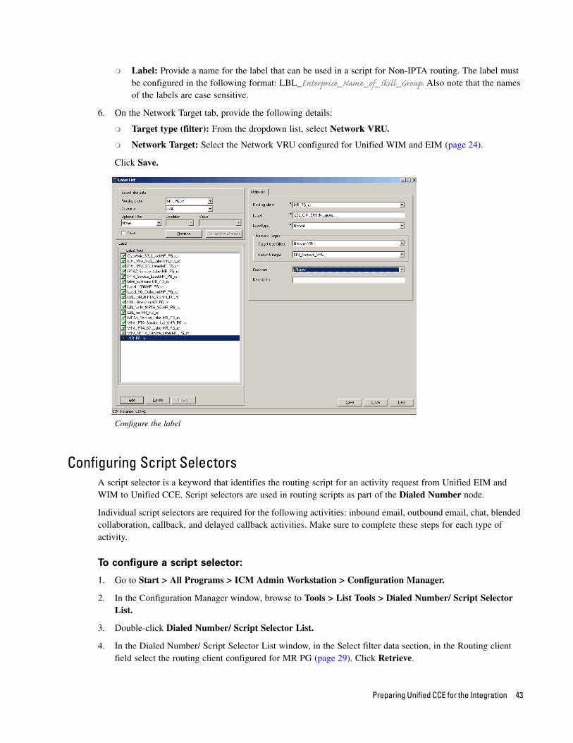
Label: Provide a name for the label that can be used in a script for Non-IPTA routing. The label must be configured in the following format: LBL_Enterprise_Name_of_Skill_Group. Also note that the names of the labels are case sensitive.
6. On the Network Target tab, provide the following details:
Target type (filter): From the dropdown list, select Network VRU.
Network Target: Select the Network VRU configured for Unified WIM and EIM (page 24).
Click Save.
Configure the label
Configuring Script SelectorsA script selector is a keyword that identifies the routing script for an activity request from Unified EIM and WIM to Unified CCE. Script selectors are used in routing scripts as part of the Dialed Number node.
Individual script selectors are required for the following activities: inbound email, outbound email, chat, blended collaboration, callback, and delayed callback activities. Make sure to complete these steps for each type of activity.
To configure a script selector:
1. Go to Start > All Programs > ICM Admin Workstation > Configuration Manager.
2. In the Configuration Manager window, browse to Tools > List Tools > Dialed Number/ Script Selector List.
3. Double-click Dialed Number/ Script Selector List.
4. In the Dialed Number/ Script Selector List window, in the Select filter data section, in the Routing client field select the routing client configured for MR PG (page 29). Click Retrieve.
Preparing Unified CCE for the Integration 43
5. In the Dialed Number/ Script Selector section, click Add.
A new entry is created and the Attributes tab becomes editable.
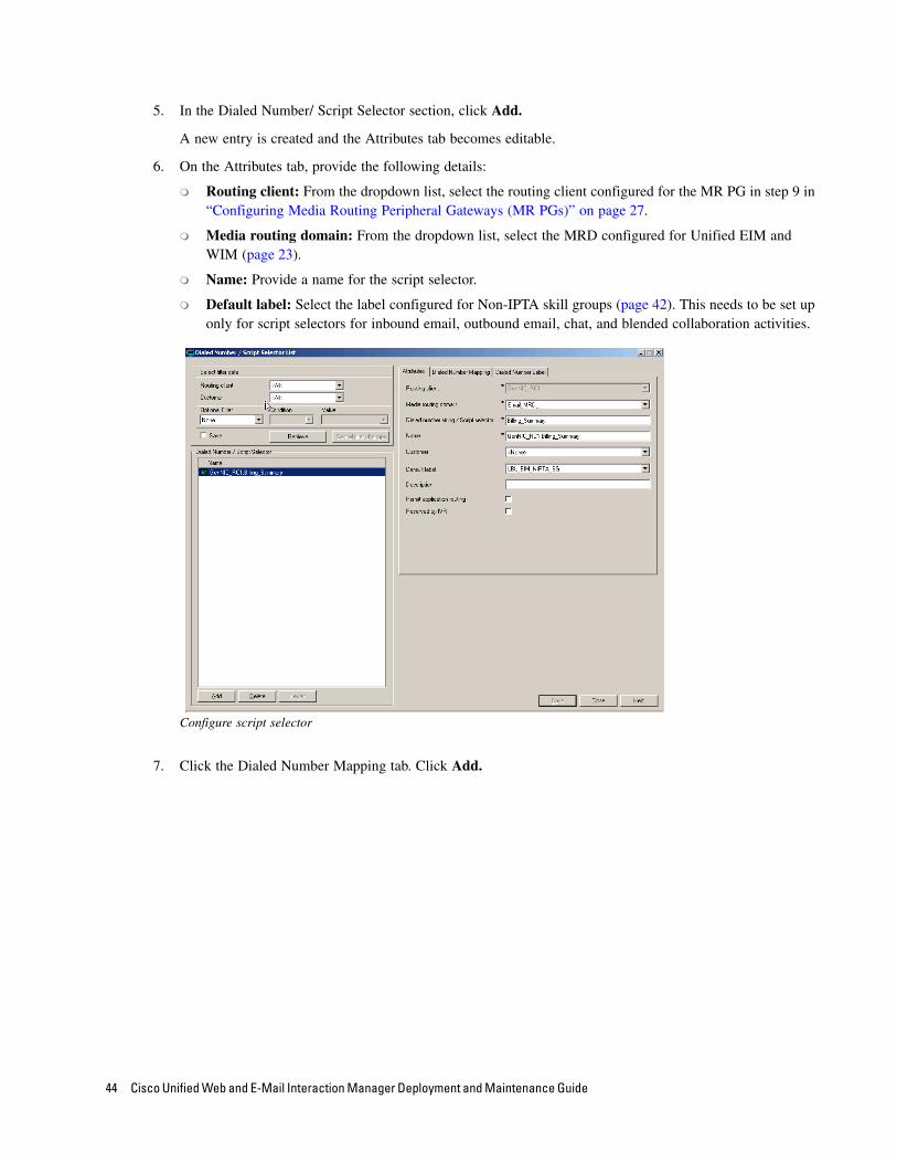
6. On the Attributes tab, provide the following details:
Routing client: From the dropdown list, select the routing client configured for the MR PG in step 9 in “Configuring Media Routing Peripheral Gateways (MR PGs)” on page 27.
Media routing domain: From the dropdown list, select the MRD configured for Unified EIM and WIM (page 23).
Name: Provide a name for the script selector.
Default label: Select the label configured for Non-IPTA skill groups (page 42). This needs to be set up only for script selectors for inbound email, outbound email, chat, and blended collaboration activities.
Configure script selector
7. Click the Dialed Number Mapping tab. Click Add.
44 Cisco Unified Web and E-Mail Interaction Manager Deployment and Maintenance Guide
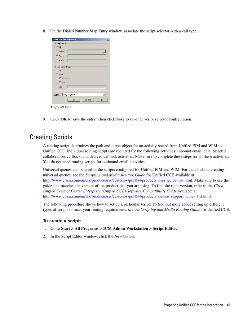
8. On the Dialed Number Map Entry window, associate the script selector with a call type.
Map call type
9. Click OK to save the entry. Then click Save to save the script selector configuration.
Creating ScriptsA routing script determines the path and target object for an activity routed from Unified EIM and WIM to Unified CCE. Individual routing scripts are required for the following activities: inbound email, chat, blended collaboration, callback, and delayed callback activities. Make sure to complete these steps for all these activities. You do not need routing scripts for outbound email activities.
Universal queues can be used in the scripts configured for Unified EIM and WIM. For details about creating universal queues, see the Scripting and Media Routing Guide for Unified CCE available at http://www.cisco.com/en/US/products/sw/custcosw/ps1844/products_user_guide_list.html. Make sure to use the guide that matches the version of the product that you are using. To find the right version, refer to the Cisco Unified Contact Center Enterprise (Unified CCE) Software Compatibility Guide available at http://www.cisco.com/en/US/products/sw/custcosw/ps1844/products_device_support_tables_list.html.
The following procedure shows how to set up a particular script. To find out more about setting up different types of scripts to meet your routing requirements, see the Scripting and Media Routing Guide for Unified CCE.
To create a script:
1. Go to Start > All Programs > ICM Admin Workstation > Script Editor.
2. In the Script Editor window, click the New button.
Preparing Unified CCE for the Integration 45
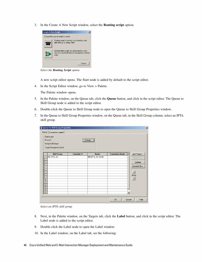
3. In the Create A New Script window, select the Routing script option.
Select the Routing Script option
A new script editor opens. The Start node is added by default to the script editor.
4. In the Script Editor window, go to View > Palette.
The Palette window opens.
5. In the Palette window, on the Queue tab, click the Queue button, and click in the script editor. The Queue to Skill Group node is added to the script editor.
6. Double-click the Queue to Skill Group node to open the Queue to Skill Group Properties window.
7. In the Queue to Skill Group Properties window, on the Queue tab, in the Skill Group column, select an IPTA skill group.
Select an IPTA skill group
8. Next, in the Palette window, on the Targets tab, click the Label button, and click in the script editor. The Label node is added to the script editor.
9. Double-click the Label node to open the Label window.
10. In the Label window, on the Label tab, set the following:
46 Cisco Unified Web and E-Mail Interaction Manager Deployment and Maintenance Guide

a. Select the label type as Configured.
b. From the available labels select a label and click the Add button. Click OK.
Select the label type and a label
11. Next, in the Palette window, on the General tab, click the Line Connector button and configure the success and error paths for each node. This creates the routing path of the script.
12. Click the Validate Script button to check if the script is created properly. If there are any errors, fix them.
13. Click the Save button to save the script.
A sample script
Preparing Unified CCE for the Integration 47
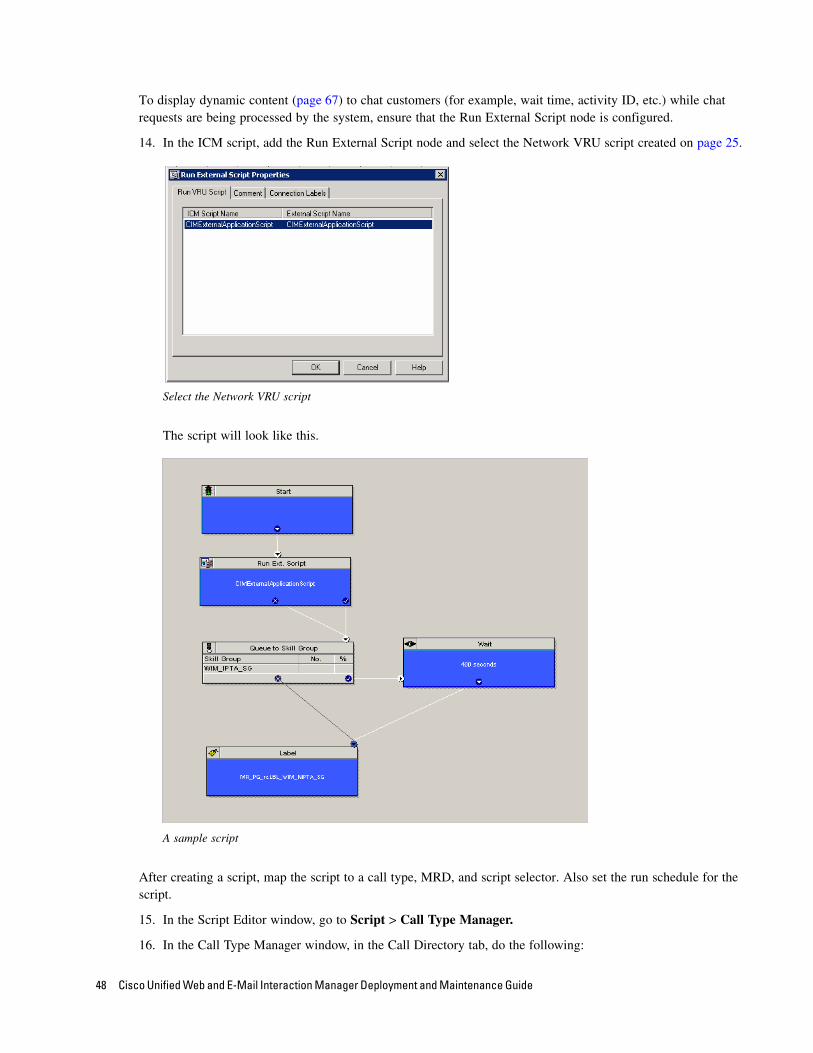
To display dynamic content (page 67) to chat customers (for example, wait time, activity ID, etc.) while chat requests are being processed by the system, ensure that the Run External Script node is configured.
14. In the ICM script, add the Run External Script node and select the Network VRU script created on page 25.
Select the Network VRU script
The script will look like this.
A sample script
After creating a script, map the script to a call type, MRD, and script selector. Also set the run schedule for the script.
15. In the Script Editor window, go to Script > Call Type Manager.
16. In the Call Type Manager window, in the Call Directory tab, do the following:
48 Cisco Unified Web and E-Mail Interaction Manager Deployment and Maintenance Guide

a. In the Media Routing Domain field, from the dropdown list, select the MRD configured for Unified EIM and WIM (page 23).
b. In the Script Type Selector field, from the dropdown list, select the script selector created for the MRD (page 43).
c. Next, click the Add button. The Add Call Type Selector Entry window appears. In the Call type field, select the call type configured for Unified WIM and EIM (page 26). Click OK.
Map the script to a call type, MRD, and script selector
17. In the Call Type Manager window, in the Schedule tab, do the following:
a. In the Call type field, from the dropdown list, select the same call type you selected in Step 16.
b. Next, click the Add button. In the Add Call Type Schedule window that appears, do the following:
i. In the Script tab, select the script configured for Unified WIM and EIM (page 45).
ii. In the Period tab, set a schedule for the script.
iii. Click OK.
Set a schedule for the script
18. Click OK to close the Call Type Manager window.
Preparing Unified CCE for the Integration 49

Configuring Device TargetsIndividual device targets are required for routing voice calls for blended collaboration, callback, and delayed callback activities. Complete these steps for all these activities. Device targets are not needed for inbound email, outbound email, and chat activities.
To configure a device target:
1. Go to Start > All Programs > ICM Admin Workstation > Configuration Manager.
2. In the Configuration Manager window, browse to Tools > Explorer Tools > Device Target Explorer.
3. Double-click Device Target Explorer.
4. In the Device Target Explorer window, click Add Device Target.
5. Provide the name and global address, which is the host name of the Unified CCE server followed by the agent extension, in the following format: Unified_CCE_Server Agent_Extension
6. Provide the configuration parameter in the following format. The string before the agent extension must be exactly as specified: /devtype CiscoPhone /dn Agent_Extension
7. Click the Add Label button.
The Label tab appears.
8. On the Label tab, set the following:
Routing client: From the dropdown list, select the MR PG configured for Unified WIM and EIM (page 27).
Label: Provide the name of the label. The label name must be the Agent_Extension.
9. Click Save.
Configure a device target
50 Cisco Unified Web and E-Mail Interaction Manager Deployment and Maintenance Guide
Configuring Expanded Call Context (ECC) VariablesECC variables are used in Unified CCE scripts to facilitate and influence routing. ECC variables have a maximum length of 256 characters. Both Scalar and Array ECC variables are supported.
ECC variables are required for inbound email, outbound email, chat, blended collaboration, callback, and delayed callback activities. Create the following ECC variables:
For inbound and outbound email activities: user.cim.activity.id
For chat activities: user.cim.activity.id, user.wim.customer.name
For blended collaboration, callback and delayed callback activities: user.cim.activity.id, user.wim.customer.name, user.cisco.cmb, user.cisco.cmb.callclass
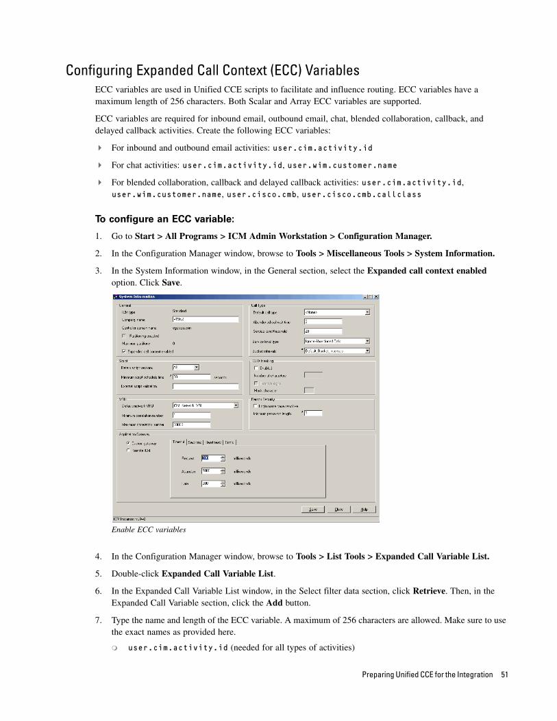
To configure an ECC variable:
1. Go to Start > All Programs > ICM Admin Workstation > Configuration Manager.
2. In the Configuration Manager window, browse to Tools > Miscellaneous Tools > System Information.
3. In the System Information window, in the General section, select the Expanded call context enabled option. Click Save.
Enable ECC variables
4. In the Configuration Manager window, browse to Tools > List Tools > Expanded Call Variable List.
5. Double-click Expanded Call Variable List.
6. In the Expanded Call Variable List window, in the Select filter data section, click Retrieve. Then, in the Expanded Call Variable section, click the Add button.
7. Type the name and length of the ECC variable. A maximum of 256 characters are allowed. Make sure to use the exact names as provided here.
user.cim.activity.id (needed for all types of activities)
Preparing Unified CCE for the Integration 51

user.wim.customer.name (needed for chat, blended collaboration, callback, and delayed callback activities)
user.cisco.cmb (needed for blended collaboration, callback, and delayed callback activities)
user.cisco.cmb.callclass (needed for blended collaboration, callback, and delayed callback activities)
8. Click Save.
Configure ECC variables
Installing Unified EIM and WIM and the Integration
For details about performing the tasks mentioned in this section, see the Cisco Unified Web and E-Mail Interaction Manager Installation Guide.
To install Unified EIM and WIM and the integration with Unified CCE:
1. Ensure that Microsoft SQL Server 2008 R2 is installed and running on the machine on which the Unified EIM and WIM databases will be installed.
2. From the Unified EIM and WIM Environment CD, copy the JBoss folder to a local directory on the Unified EIM and WIM messaging server and all application servers.
3. From the JBoss folder inside the local directory, extract the files from the jboss-as-7.1.2.Final.zip file to the location where JBoss is to be installed.
4. In distributed-server installations, install Install JDK 1.7 Update 2 or higher (64-bit) on all machines where the services server, messaging server, and application servers are to be installed. The installation program for JDK 1.7 Update 7 is included in the Environment folder of the installation package.
5. On the web server machines, install Microsoft IIS.
52 Cisco Unified Web and E-Mail Interaction Manager Deployment and Maintenance Guide
6. Install Unified EIM and WIM. Refer to the Cisco Unified Web and E-Mail Interaction Manager Installation Guide for Unified CCE for a detailed list of deployment options and installation steps corresponding to each deployment. The document also guides you through the procedure of setting up the integration. See the section “Integrating Cisco Interaction Manager with Unified CCE.”
7. Install all the maintenance releases available for 9.0(1). For installation instructions, refer to the release notes available at http://www.cisco.com/en/US/products/ps7233/prod_release_notes_list.html.
8. From the Windows Services panel, start the Cisco service, and wait for 2–3 minutes before launching the URL to allow all the application services to start.
9. On the user desktops, install Sun JRE 1.6.0 (Update 30 or higher). Version 1.6.0_30 is included on the product CD.
10. Configure the browser on user desktops according to the procedures detailed in the Cisco Unified Web and E-Mail Interaction Manager Browser Settings Guide.
Preparing Cisco Media Blender for the Integration
The Cisco Media Blender (CMB) integrates with Unified CCE to blend chat and voice into a blended collaboration session for an agent and a customer. The interface interacts with the Agent PG (Call Manager PG) to facilitate voice call generation and voice monitoring within Unified CCE.
For each Agent PG that is configured for Unified EIM and WIM, you need to install and configure a dedicated instance of CMB.
Installing Cisco Media Blender
To install Cisco Media Blender:
1. Run the Cisco Media Blender Setup.exe. For more details, refer to the Cisco Media Blender Installation Guide.
2. Apply patches, if any.
3. Restart the server after installation is complete.
Configuring Cisco Media BlenderRefer to the Cisco Media Blender Administration Guide for Cisco ICM/IPCC Enterprise & Hosted Editions for more information about configuring Cisco Media Blender.
Configuring Cisco Media Blender for Unified CCE
To configure Cisco Media Blender for Unified CCE:
1. Open a web browser and launch the URL: http://Cisco Media Blender Server Name:8080/cmb
The Cisco Media Blender Administration page appears.
Preparing Unified CCE for the Integration 53

2. In the Cisco Media Blender Administration page, browse to Media Blender > Server > Properties.
3. Go to the CTI tab, and set the following properties.
Peripheral Type: Set the value as IPCC.
CTI Strategy: Set the value as AgentReserved.
Peripheral ID: Provide the peripheral ID of the Agent PG.
Peripheral Host Name: Provide the CTI server hostname.
Peripheral Host Port: Provide the port of the CTI Server.
Peripheral Username: Set the value to be the hostname of the Cisco Media Blender server. The recommended form is cmb-hostname of the Cisco Media Blender machine, but it works by just defining the hostname of the Cisco Media Blender machine.
Auto Answer: The value of this property is automatically set to False and it cannot be changed.
Permitted Phonenum Length: Disable this property by selecting the Disable check box.
Set the CTI properties
4. Go to the Collaboration tab, and set the following properties.
Remote Registry Port: Provide the registry port to be used to communicate with Cisco Interaction Manager. Cisco recommends that this is a different port from the port chosen as the RMI port (15099) when Unified EIM and WIM was installed.
Remote Password: Provide a remote password.
Local Registry Port: Provide the local registry port. The default value is 1099.
54 Cisco Unified Web and E-Mail Interaction Manager Deployment and Maintenance Guide
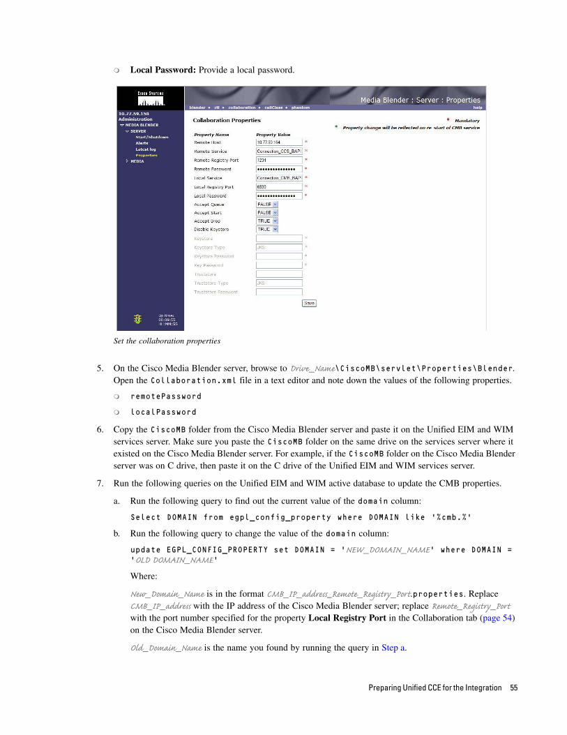
Local Password: Provide a local password.
Set the collaboration properties
5. On the Cisco Media Blender server, browse to Drive_Name\CiscoMB\servlet\Properties\Blender. Open the Collaboration.xml file in a text editor and note down the values of the following properties.
remotePassword
localPassword
6. Copy the CiscoMB folder from the Cisco Media Blender server and paste it on the Unified EIM and WIM services server. Make sure you paste the CiscoMB folder on the same drive on the services server where it existed on the Cisco Media Blender server. For example, if the CiscoMB folder on the Cisco Media Blender server was on C drive, then paste it on the C drive of the Unified EIM and WIM services server.
7. Run the following queries on the Unified EIM and WIM active database to update the CMB properties.
a. Run the following query to find out the current value of the domain column:
Select DOMAIN from egpl_config_property where DOMAIN like '%cmb.%'
b. Run the following query to change the value of the domain column:
update EGPL_CONFIG_PROPERTY set DOMAIN = 'NEW_DOMAIN_NAME' where DOMAIN = 'OLD DOMAIN_NAME'
Where:
New_Domain_Name is in the format CMB_IP_address_Remote_Registry_Port.properties. Replace CMB_IP_address with the IP address of the Cisco Media Blender server; replace Remote_Registry_Port with the port number specified for the property Local Registry Port in the Collaboration tab (page 54) on the Cisco Media Blender server.
Old_Domain_Name is the name you found by running the query in Step a.
Preparing Unified CCE for the Integration 55
c. Run the following query to change the value of the property WLRoot. For example, if the Cisco MB folder has been copied (Step 5) to C:\, then WLRoot should be updated to C:\\CiscoMB by running the following query:
Update egpl_config_property set Value='C:\\CiscoMB' where domain='cmb.CMB_Ip_Address_Remote_Registry_Port.properties' and NAME = 'WLROOT'
Where: cmb.CMB_Ip_Address_Remote_Registry_Port.properties is the domain name configured in Step b.
d. Run the following query to change the value of the property RemoteHost:
update EGPL_CONFIG_PROPERTY set VALUE = 'Remote_Host' where DOMAIN='cmb.CMB_Ip_Address_Remote_Registry_Port.properties' and NAME='RemoteHost'
Where:
Remote_Host is the IP address of the Cisco Media Blender server.
cmb.CMB_Ip_Address_Remote_Registry_Port.properties is the domain name configured in Step b.
e. Run the following query to change the value of the property RemoteRegistryPort:
update EGPL_CONFIG_PROPERTY set VALUE = 'Remote_Registry_Port' where DOMAIN='cmb.CMB_Ip_Address_Remote_Registry_Port.properties' and NAME='RemoteRegistryPort'
Where:
Remote_Registry_Port should be the same as the port specified for the property Local Registry Port in the Collaboration tab on page 54.
cmb.CMB_Ip_Address_Remote_Registry_Port.properties is the domain name configured in Step b.
f. Run the following query to change the value of the property LocalRegistryPort:
update EGPL_CONFIG_PROPERTY set VALUE = 'Local_Registry_Port' where DOMAIN='cmb.CMB_Ip_Address_Remote_Registry_Port.properties' and NAME='LocalRegistryPort'
Where:
Local_Registry_Port should be the same as the port specified for the property Remote Registry Port in the Collaboration tab on page 54.
cmb.CMB_Ip_Address_Remote_Registry_Port.properties is the domain name configured in Step b.
g. Run the following query to change the value of the property LocalPassword:
update EGPL_CONFIG_PROPERTY set VALUE = ‘Password_Value’ where DOMAIN='cmb.CMB_Ip_Address_Remote_Registry_Port.properties' and NAME= ‘LocalPassword’
Where:
Password_Value is the remotePassword you noted down in Step 5.
cmb.CMB_Ip_Address_Remote_Registry_Port.properties is the domain name configured in Step b.
h. Run the following query to change the value of the property RemotePassword:
56 Cisco Unified Web and E-Mail Interaction Manager Deployment and Maintenance Guide
update EGPL_CONFIG_PROPERTY set VALUE = ‘Password_Value’ where DOMAIN='cmb.CMB_Ip_Address_Remote_Registry_Port.properties' and NAME= ‘RemotePassword’
Where:
Password_Value is the localPassword you noted down in Step 5.
cmb.CMB_Ip_Address_Remote_Registry_Port.properties is the domain name configured in Step b.
Configuring the System for Multiple Agent PGs
Multiple Agent PGs can be used for Unified CCE installations. A maximum of four Agent PGs are supported for each deployment of Unified EIM and WIM. Note that a unique application path and associated application path members are needed for each Agent PG. The application path is used by the Listener Service to connect and communicate with the Agent PG.
To configure the system for multiple Agent PGs:
1. Create the Agent PGs. For Unified CCE installations, see page 32.
2. In Unified CCE, configure agents (page 37) and skill groups (page 38).
3. Run the Cisco Interaction Manager Integration Wizard to import the Agent PGs. For each Agent PG that is imported, a Listener instance is created in the System Console. Refer to the Cisco Unified Web and E-Mail Interaction Manager Installation Guide for Unified CCE for details about running the wizard.
4. Log in to the Cisco Integration Manager System Console.
5. Browse to Shared Resource > Services > Listener > Listener. In the List pane, select the Listener process. In the Properties pane, in the Maximum number of instances field set the value as 4.
6. Browse to Partitions > Partition. In the Properties pane, on the Services tab, set the number of instances for the Listener service to 4.
7. Browse to Partitions > Partition > Services > Listener > Listener. For the Listener instances, set the CMB parameters. Start the service instances.
For details about steps 4-7, see the Cisco Unified Web and E-Mail Interaction Manager Administrator's Guide to System Console.
Important: After installing Unified EIM and WIM, you need to configure the CMB parameters in
the Listener service instance from the System Console of Unified EIM and WIM. For details
about completing this task, see the Cisco Unified Web and E-Mail Interaction Manager
Administrator's Guide to System Console.
Preparing Unified CCE for the Integration 57
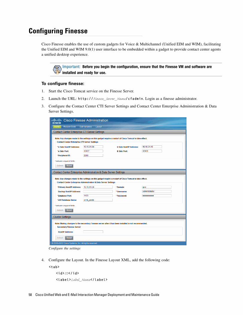
Configuring Finesse
Cisco Finesse enables the use of custom gadgets for Voice & Multichannel (Unified EIM and WIM), facilitating the Unified EIM and WIM 9.0(1) user interface to be embedded within a gadget to provide contact center agents a unified desktop experience.
To configure finesse:
1. Start the Cisco Tomcat service on the Finesse Server.
2. Launch the URL: http://Finesse_Server_Name/cfadmin. Login as a finesse administrator.
3. Configure the Contact Center CTI Server Settings and Contact Center Enterprise Administration & Data Server Settings.
Configure the settings
4. Configure the Layout. In the Finesse Layout XML, add the following code:
<tab>
<id>ID</id>
<label>Label_Name</label>
Important: Before you begin the configuration, ensure that the Finesse VM and software are
installed and ready for use.
58 Cisco Unified Web and E-Mail Interaction Manager Deployment and Maintenance Guide

<gadgets>
<gadget>http://Web_Server_Name/cim.xml</gadget>
</gadgets>
</tab>
Where:
ID: Provide an ID for the new gadget. Make sure that the ID name does not have any spaces. For example, UnifiedEmailandWebInteractionManager.
Label_Name: Provide a label for the gadget. For example, Unified Email and Web Interaction Manager.
Web_Server_Name: Name of the Unified EIM and WIM web server. If you have more than one web servers and you are using a loadbalancer for the web servers, provide the name of the loadbalancer server.
Configure the layout
5. From the Unified EIM and WIM installation package, copy the Finesse folder on the Unified EIM and WIM web servers. Unzip the contents of the cim-gadget.zip file to C:\Inetpub\WWWRoot. Open the cim.xml in a text editor and locate EIM WIM Server Name and replace it with the name of the web server. Next replace “system” with the context root name used for the Unified EIM and WIM installation.
Preparing Unified CCE for the Integration 59
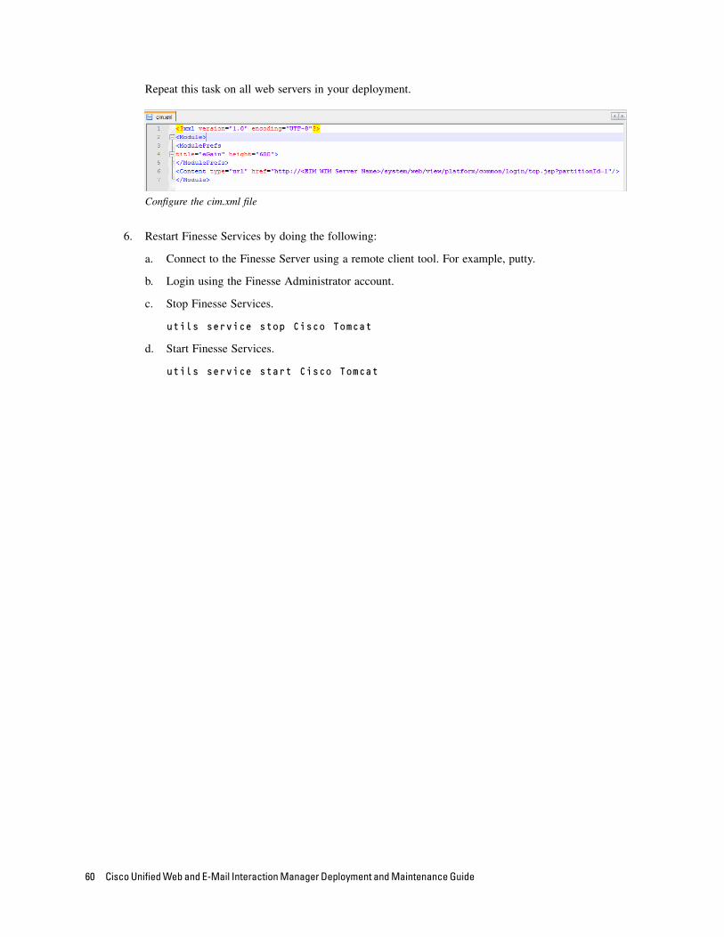
Repeat this task on all web servers in your deployment.
Configure the cim.xml file
6. Restart Finesse Services by doing the following:
a. Connect to the Finesse Server using a remote client tool. For example, putty.
b. Login using the Finesse Administrator account.
c. Stop Finesse Services.
utils service stop Cisco Tomcat
d. Start Finesse Services.
utils service start Cisco Tomcat
60 Cisco Unified Web and E-Mail Interaction Manager Deployment and Maintenance Guide
Setting Up Integrated
Objects
Configuring Variables in Unified EIM and WIM
Verifying Mapping of Objects in the Administration Console
Setting Up Knowledge Base Articles for Unified EIM
Setting up Business Objects in the Administration Console
Setting Up Services in the System Console
Setting Up Web Links for Chat and Collaboration
Configuring Dynamic Messages for Integrated Chats
Handling Email Assignment
Related Documentation

This chapter provides an overview of the process of setting up Unified WIM and EIM–Unified CCE objects.
Configuring Variables in Unified EIM and WIM
While sending new activity requests from a queue to Unified CCE, EAAS sends call variables and ECC variables to Unified CCE as task context. By default, the following activity attributes are sent to Unified CCE as ECC variables.
For inbound and outbound email activities: activity_id
For chat activities: activity_id, customer_name
For callback and delayed callback activities: activity_id, customer_name, cmb_param, cti_strategy
For blended collaboration activities: activity_id, customer_name, cmb_param, cti_strategy
If you need to pass on other attributes of the activity as call variables or ECC variables to Unified CCE, you need to configure them in Unified EIM and WIM. These variables can then be used in Unified CCE scripts to configure conditions. For details, see the Unified CCE scripts documentation. If you plan to configure these variables as ECC variables in Unified EIM and WIM, you need to first create the ECC variables in Unified CCE. For details, see the Unified CCE documentation.
You can also create variables for custom activity attributes. For details about creating variables, see the “Call Variables” chapter in the Cisco Unified Web and E-Mail Interaction Manager Administrator's Guide to Routing and Workflows.
Verifying Mapping of Objects in the Administration Console
To verify that Unified CCE objects have been mapped correctly in the Unified EIM and
WIM Administration Console:
1. Launch the URL: http://Unified EIM and WIM_Server/Default_Partition.
2. Log in as the partition administrator (user name and password that were configured during the installation of Unified EIM and WIM). Go to the Administration Console.
3. Under Partition, browse to Settings. Locate the Application Instance communication setting. Verify that it is set to the value chosen at the time of running the Unified CCE integration wizard. For details, see the Cisco Unified Web and E-Mail Interaction Manager Administrator’s Guide to Administration Console.
4. Under the appropriate department, browse to the User > Users node in the Administration tree, to verify that all users mapping to the administrators, supervisors, and agents, which were selected at the time of running the integration wizard, are displayed. Note that after the integration wizard is run, additional mapped users can be created from the Administration Console. For details, see the Cisco Unified Web and E-Mail Interaction Manager Administrator’s Guide to Administration Console.
62 Cisco Unified Web and E-Mail Interaction Manager Deployment and Maintenance Guide

5. Under the appropriate department, click the User > Groups node in the Administration tree to verify that all user groups mapping to the skill groups, which were selected at the time of running the integration wizard, are displayed. Note that after the integration wizard is run, additional mapped user groups can be created from the Administration Console. For details, see the Cisco Unified Web and E-Mail Interaction Manager Administrator’s Guide to Administration Console.
6. Under the appropriate department, click the Workflow > Queues node in the Administration tree, and verify that all queues mapping to the MRDs, which were selected at the time of running the Unified CCE integration wizard, are displayed. Also verify that for all the non-IPTA skill groups that were imported using the Unified CCE integration wizard, the corresponding queues have been automatically created under the Queues node. Note that after the integration wizard is run, additional mapped queues can be created from the Administration Console. For details, see the Cisco Unified Web and E-Mail Interaction Manager Administrator’s Guide to Routing and Workflows.
Setting Up Knowledge Base Articles for Unified EIM
The knowledge base (KB) consists of articles organized into folders. It includes certain standard folders to hold articles meant for specific use in emails, such as headers, greetings, signatures, and footers. Folders for articles of other types are created by KB managers and authors.
See the Cisco Unified Web and E-Mail Interaction Manager Knowledge Base Author’s Guide for the details of the procedures mentioned in this section.
To set up KB articles for Unified EIM:
1. Launch the URL: http://Unified EIM and WIM_Server/Default_Partition.
2. Log in as the partition administrator.
3. Open the Knowledge Base Console.
4. In the Knowledge Base tree, browse to Departments > Department_Name > Content > Shared > Standard > Email. Create an article in each of the sub-nodes to set up one option each for a header, greeting, signature, and footer that can be used in responses to incoming activities in the department. Set up macros for the articles to make it easy to insert them into other articles or email responses.
5. Browse to the Department > Shared folder. Create a folder for auto-acknowledgements.
6. In the newly created folder, create an article for use in auto-acknowledgement emails. Use macros to insert the header, greeting, signature, and footer created earlier. These macros expand to the actual content at runtime.
This article will be used later in a workflow (see page 64).
Setting Up Integrated Objects 63
Setting up Business Objects in the Administration Console
Unified EIM ObjectsSee the Cisco Unified Web and E-Mail Interaction Manager Administrator’s Guide to Email Resources and the Cisco Unified Web and E-Mail Interaction Manager Administrator’s Guide to Routing and Workflows for the details of the procedures mentioned in this section.
To set up Unified EIM business objects in the Administration Console:
1. Launch the URL: http://Unified EIM and WIM_Server/Default_Partition.
2. Log in as the partition administrator and go to the Administration Console.
3. In the Administration tree, browse to the Administration > Departments > Department_Name > Classifications > Categories node. Create categories.
These categories will be used later in a workflow (see page 64).
4. Now, browse to the Email > Aliases node. Create an alias to serve as the entry point for emails into the system.
5. Next, browse to the Workflow > Queues node to create an email queue. Skip this step if you want to use an auto-configured queue (see page 63).
6. Then, browse to the Workflow > Workflows > Inbound node to create an inbound workflow for this alias. The workflow will route incoming emails. Add the alias created in Step 4 to the Start node. Add the auto-configured queues or use the queues created in Step 5 to the Queue node. Select the auto-acknowledgement KB article created earlier (see page 63) for the Auto-acknowledgement node. Select the categories created in Step 3 for the Classifications node.
Unified WIM ObjectsSee Cisco Unified Web and E-Mail Interaction Manager Administrator’s Guide to Chat and Collaboration Resources for the details of the procedures mentioned in this section.
To set up Unified WIM business objects in the Administration Console:
1. Launch the URL: http://Unified EIM and WIM_Server/Default_Partition.
2. Log in as the partition administrator and go to the Administration Console.
3. Browse to the Workflow > Queues node and create chat, blended collaboration, callback, and delayed callback queues. Skip this step if you want to use auto-configured queues (see page 63).
4. Browse to the Chat > Entry points node. Create new entry points by assigning the appropriate templates. To route chats, blended collaboration, and call back activities that enter from this entry point, use an auto-configured queue or the queue created in Step 3. Make the entry points active. The configuration steps for entry points are different for different types of activities and routing options.
The activity types for which you need to create entry points are: Chat, Blended Collaboration, Callback, Delayed callback.
64 Cisco Unified Web and E-Mail Interaction Manager Deployment and Maintenance Guide
The two routing options available are: Cisco Interaction Manager and Unified CCE.
5. In the Properties pane, click the Show HTML button. The code used to generate a chat hyperlink to that entry point is displayed. Copy this link code into a Notepad file. Edit the code as explained in the Cisco Unified Web and E-Mail Interaction Manager Administrator’s Guide to Chat and Collaboration Resources.
Setting Up Services in the System Console
Service processes are managed at the system level as shared resources across partitions. Service instances are managed within partitions.
See Cisco Unified Web and E-Mail Interaction Manager Administrator's Guide to System Console for the details of the procedures mentioned in this section.
Unified EIM ServicesThis section helps you set up processes and instances for the following services:
Retriever: Gets incoming emails from configured aliases and parses them.
Workflow Cache: Maintains the files that store information about objects used in workflows.
Workflow Engine: Applies workflows on emails to automate their routing and handling.
Dispatcher: Sends outgoing emails out of the system.
External Agent Assignment Service (EAAS): Identifies new activities that arrive into an external assignment queue, and routes requests for each of these activities to Unified CCE for routing to take place through Unified CCE.
Listener: Assigns activities to target agents or user groups (skill groups) identified by Unified CCE, and reports the status of both the activity and the agent to Unified CCE throughout the life cycle of the given activity.
To set up Unified EIM services in the System Console:
See Cisco Unified Web and E-Mail Interaction Manager Administrator's Guide to System Console for the details of the procedures mentioned in this section.
1. Open a new browser window, and launch the URL: http://Unified EIM and WIM_Server/Context_Root. Log in as the system administrator (user name and password that were configured during the installation of Unified EIM and WIM). Go to the System Console.
2. Browse to the Partitions > Partition > Services > Email > Retriever node. Click the Retriever instance to use in the partition, and select the email alias that you had created earlier in the Administration Console (see page 64).
3. Restart the Retriever process and instance based on the notification message that appears. Browse to Shared Resource > Services > Retriever, and stop and start the Retriever process for the system. Also ensure that the start type for the service process is set to automatic.
4. Navigate back to the Partitions > Partition > Services > Retriever node. Ensure that the start type for the service instance is set to automatic. Stop and start the Retriever instance.
Setting Up Integrated Objects 65

5. Browse to Shared Resource > Services > Workflow > Workflow Cache and verify that the Workflow Cache process is running. If the process is in a stopped state, start the process by clicking the Run button. Also ensure that the start type for the service process is set to automatic.
6. Browse to Partitions > Partition > Services > Workflow > Workflow Cache and ensure that the start type for the service instance is set to automatic. Start the Workflow Cache instance.
7. Browse to Shared Resource > Services > Workflow > Workflow Engine and verify that the Workflow Engine process is running. If the process is in a stopped state, start the process by clicking the Run button. Also ensure that the start type for the service process is set to automatic.
8. Browse to Partitions > Partition > Services > Workflow > Workflow Engine and ensure that the start type for the service instance is set to automatic. Start the Workflow Engine instance.
9. Browse to Shared Resource > Services > Email > Dispatcher and verify that the Dispatcher process is running. If the process is in a stopped state, start the process by clicking the Run button. Also ensure that the start type for the service process is set to automatic.
10. Browse to Partitions > Partition > Services > Email > Dispatcher and ensure that the start type for the service instance is set to automatic. Start the Dispatcher instance.
11. Browse to Shared Resource > Services > Listener > Listener and verify that the Listener process is running. If the process is in a stopped state, start the process by clicking the Run button. Also ensure that the start type for the service process is set to automatic.
12. Browse to Partitions > Partition > Services > Listener > Listener. Verify that the Listener instance for the Agent PG is automatically created. Also ensure that the start type for the instance is set to automatic. Then start the Listener instance.
13. Browse to Shared Resource > Services > EAAS > EAAS and verify that the EAAS process is running. If the process is in a stopped state, start the process by clicking the Run button. Also ensure that the start type for the service process is set to automatic.
14. Browse to Partitions > Partition > Services > EAAS > EAAS. Configure the EAAS instance by providing the MR Connection port number you provided while creating the MR PIM (page 27). Also ensure that the start type for the instance is set to automatic. Start the EAAS instance.
Unified EIM is now ready for use. To verify, log in as an agent, supervisor, or administrator and perform basic tasks.
Unified WIM ServicesThis section helps you set up processes and instances for the following services:
External Agent Assignment Service (EAAS): Identifies new activities that arrive into an external assignment queue, and routes requests for each of these activities to Unified CCE for routing to take place through Unified CCE.
Listener: Assigns activities to target agents or user groups (skill groups) identified by Unified CCE, and reports the status of both the activity and the agent to Unified CCE throughout the life cycle of the given activity.
66 Cisco Unified Web and E-Mail Interaction Manager Deployment and Maintenance Guide

To set up Unified WIM services in the System Console:
Follow the instructions in steps 11-14 in “Unified EIM Services” on page 65. In addition to the fields mentioned in Step 12, configure the CMB parameters fields for each listener service instance.
Setting Up Web Links for Chat and Collaboration
To create a chat and collaboration link on your web site:
Open the code view of the host web page and add the edited link code (see page 64) from the entry point properties at the appropriate point. You may need to ask your web master to perform this task.
Unified WIM is now ready for use. To verify, log in as an agent or supervisor, and perform basic tasks.
Configuring Dynamic Messages for Integrated Chats
Dynamic Run Application Script Request (DRASR) allows you to display wait messages with dynamic text (such as expected wait time) to customers while chat and call requests are being processed by the Unified WIM and Unified CCE integrated systems. You can use ECC variables and call variables to display the dynamic content. The dynamic messages are configured in the egicm_message_map.xml file. This file is available in the ipcc folder in the configuration.zip file available on the services server at the following location: Cisco_Home\eService\lib.
Configuring the dynamic messages includes the following steps:
1. Configure the Network VRU scripts in Unified CCE.
2. Identify the queues for which you want to display the dynamic messages.
3. Identify the ECC variables or call variables you want to use in the dynamic message and prepare the macros for the variables. For details about these objects and how they are used in Unified CCE, see the Scripting and Media Routing Guide for Cisco Unified ICM/Contact Center Enterprise & Hosted available here: http://www.cisco.com/en/US/products/sw/custcosw/ps1001/products_user_guide_list.html
4. Configure the dynamic message in the egicm_message_map.xml file.
Dynamic messages can be displayed for integrated chats, blended collaboration, callback, and delayed callback activities.
To configure dynamic messages for integrated chats:
1. From Unified CCE, configure the Network VRU scripts (page 25) and use them in the ICM scripts (page 45) used for chat and blended collaboration activities. You will need the name of the Network VRU script for configuring the dynamic messages.
2. From the Unified EIM and WIM Administration Console, identify the integrated chat queues and blended collaboration queues for which you want to display the dynamic messages.
3. To display the dynamic content using ECC variable macros, prepare your macros by doing the following:
Setting Up Integrated Objects 67
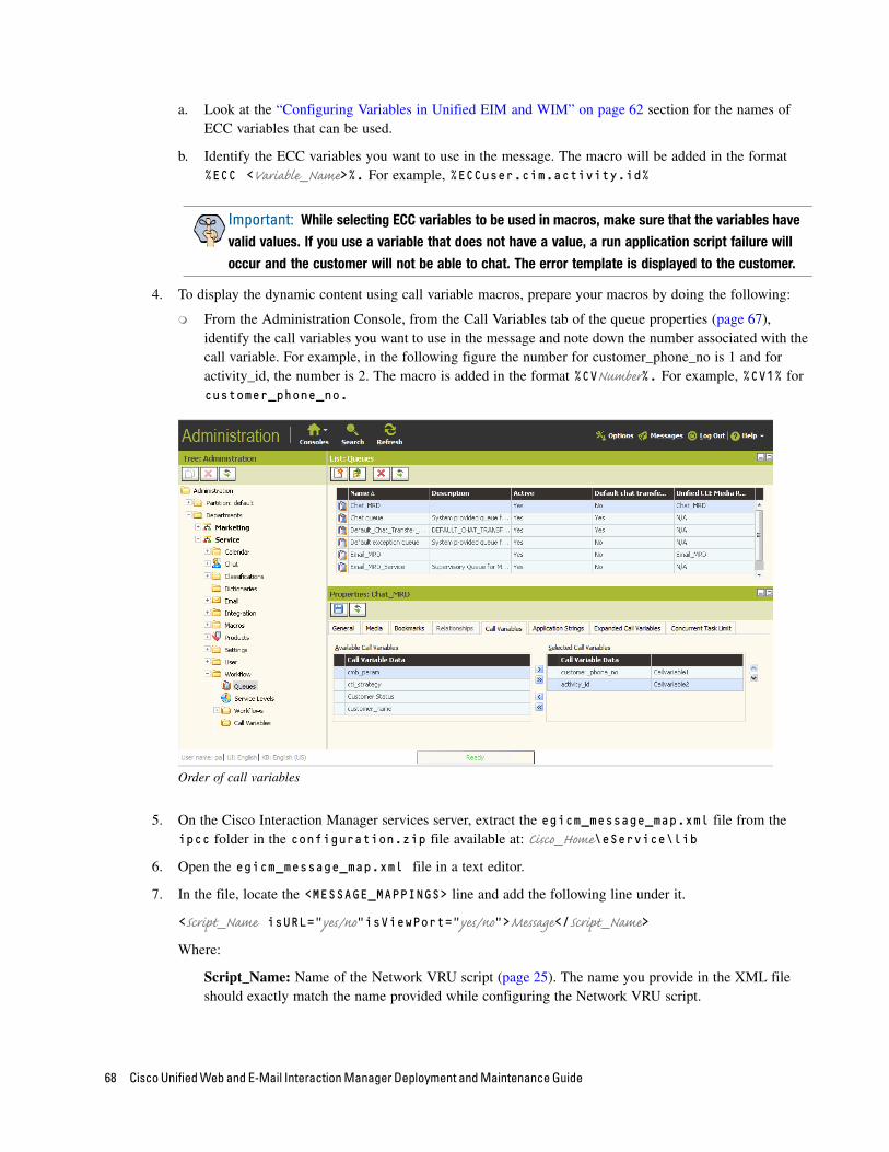
a. Look at the “Configuring Variables in Unified EIM and WIM” on page 62 section for the names of ECC variables that can be used.
b. Identify the ECC variables you want to use in the message. The macro will be added in the format %ECC <Variable_Name>%. For example, %ECCuser.cim.activity.id%
4. To display the dynamic content using call variable macros, prepare your macros by doing the following:
From the Administration Console, from the Call Variables tab of the queue properties (page 67), identify the call variables you want to use in the message and note down the number associated with the call variable. For example, in the following figure the number for customer_phone_no is 1 and for activity_id, the number is 2. The macro is added in the format %CVNumber%. For example, %CV1% for customer_phone_no.
Order of call variables
5. On the Cisco Interaction Manager services server, extract the egicm_message_map.xml file from the ipcc folder in the configuration.zip file available at: Cisco_Home\eService\lib
6. Open the egicm_message_map.xml file in a text editor.
7. In the file, locate the <MESSAGE_MAPPINGS> line and add the following line under it.
<Script_Name isURL=”yes/no”isViewPort="yes/no">Message</Script_Name>
Where:
Script_Name: Name of the Network VRU script (page 25). The name you provide in the XML file should exactly match the name provided while configuring the Network VRU script.
Important: While selecting ECC variables to be used in macros, make sure that the variables have
valid values. If you use a variable that does not have a value, a run application script failure will
occur and the customer will not be able to chat. The error template is displayed to the customer.
68 Cisco Unified Web and E-Mail Interaction Manager Deployment and Maintenance Guide
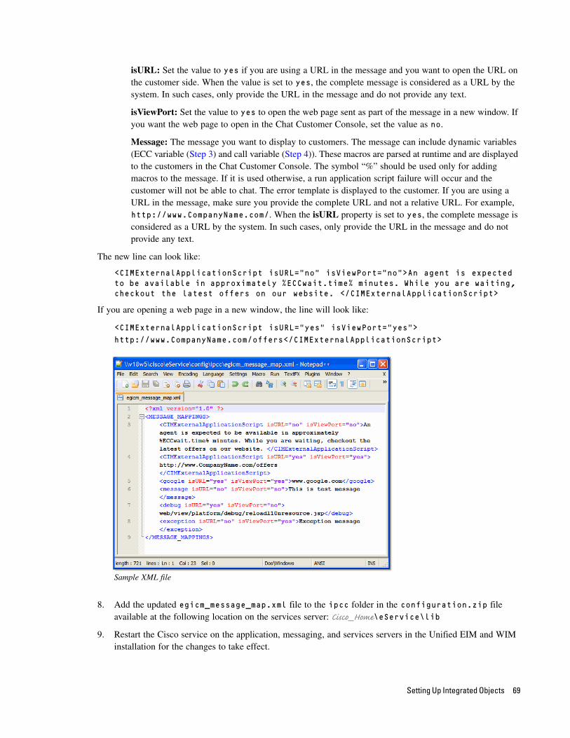
isURL: Set the value to yes if you are using a URL in the message and you want to open the URL on the customer side. When the value is set to yes, the complete message is considered as a URL by the system. In such cases, only provide the URL in the message and do not provide any text.
isViewPort: Set the value to yes to open the web page sent as part of the message in a new window. If you want the web page to open in the Chat Customer Console, set the value as no.
Message: The message you want to display to customers. The message can include dynamic variables (ECC variable (Step 3) and call variable (Step 4)). These macros are parsed at runtime and are displayed to the customers in the Chat Customer Console. The symbol “%” should be used only for adding macros to the message. If it is used otherwise, a run application script failure will occur and the customer will not be able to chat. The error template is displayed to the customer. If you are using a URL in the message, make sure you provide the complete URL and not a relative URL. For example, http://www.CompanyName.com/. When the isURL property is set to yes, the complete message is considered as a URL by the system. In such cases, only provide the URL in the message and do not provide any text.
The new line can look like:
<CIMExternalApplicationScript isURL="no" isViewPort="no">An agent is expected to be available in approximately %ECCwait.time% minutes. While you are waiting, checkout the latest offers on our website. </CIMExternalApplicationScript>
If you are opening a web page in a new window, the line will look like:
<CIMExternalApplicationScript isURL="yes" isViewPort="yes"> http://www.CompanyName.com/offers</CIMExternalApplicationScript>
Sample XML file
8. Add the updated egicm_message_map.xml file to the ipcc folder in the configuration.zip file available at the following location on the services server: Cisco_Home\eService\lib
9. Restart the Cisco service on the application, messaging, and services servers in the Unified EIM and WIM installation for the changes to take effect.
Setting Up Integrated Objects 69
Handling Email Assignment
After activities are processed by Unified EIM, EAAS changes the activity substatus to 4105 (Ready for Unified CCE routing) and sends a request to Unified CCE for further processing. If the same activities continue to remain in this substatus for a delayed period, various options exist to have EAAS retry routing of such activities through Unified CCE. The options available are:
Option 1: A maximum wait time for each mapped queue can be set. When an activity belonging to that queue reaches that time, and it has not been assigned to an agent or to an exception queue, EAAS requeues the activity again and sends a NEW_TASK request for that activity to MR PIM.
Option 2: This option can only be used when Unified CCE scripts are linear in nature. When an activity is picked for assignment, EAAS checks to see if there are any activities older than the currently picked activity that are not yet assigned to an agent or to the exception queue. If any such activities are found, EAAS requeues those activities again and send a NEW_TASK requests for them to MR PIM.
To enable option 1:
1. On the Unified EIM active database, run the following query to get the queue_ID of integrated email queues.
Select queue_ID, queue_name from EGPL_ROUTING_QUEUE
2. For each integrated email queue, run the following query to set the MAX_WAIT_TIME column value in seconds. This should be the maximum time in which you want MR PIM to respond back to a NEW_TASK request.
UPDATE EGICM_QUEUE SET MAX_WAIT_TIME = Value in seconds WHERE QUEUE_ID = Queue_ID of Integrated email queue
To enable option 2:
Run the following query on the Unified EIM active database to change the value of the setting FIFO_ALGO_TO_SAVE_EMAIL_ENABLE to True.
Update egpl_config_property set Value='true' where domain= 'ipcc.egicm_configuration.properties' and NAME = 'FIFO_ALGO_TO_SAVE_EMAIL_ENABLE'
Related Documentation
Refer to the following Unified EIM and WIM User’s Guides (for the Unified CCE integration) for more information about configuring and using Unified EIM and WIM.
Cisco Unified Web and E-Mail Interaction Manager Administrator’s Guide to Administration Console helps administrators set up and manage business objects.
Cisco Unified Web and E-Mail Interaction Manager Administrator’s Guide to Chat and Collaboration Resources helps administrators set up template sets, entry points, business rules, and cobrowse rules.
Cisco Unified Web and E-Mail Interaction Manager Administrator’s Guide to Email Resources helps administrators set up aliases, blocked addresses, delivery exceptions, and blocked file extensions.
Cisco Unified Web and E-Mail Interaction Manager Administrator’s Guide to Routing and Workflows helps administrators set up service levels, queues, and workflows.
70 Cisco Unified Web and E-Mail Interaction Manager Deployment and Maintenance Guide

Cisco Unified Web and E-Mail Interaction Manager Administrator’s Guide to Data Adapters helps administrators set up data links to connect to external sources.
Cisco Unified Web and E-Mail Interaction Manager Administrator’s Guide to System Console helps system administrators set up and manage services, loggers, and system monitors.
Cisco Unified Web and E-Mail Interaction Manager Administrator’s Guide to Tools Console helps business analysts extend the system by adding custom attributes. The Tools Console also enables administrators to configure screens and views for users and groups.
Cisco Unified Web and E-Mail Interaction Manager Supervisor’s Guide helps supervisors set up and use agent and queue monitors.
Cisco Unified Web and E-Mail Interaction Manager Administrator’s Guide to Reports Console helps managers and supervisors to set up and run reports to analyze various aspects of the system.
Cisco Unified Web and E-Mail Interaction Manager Knowledge Base Author’s Guide helps knowledge base (KB) managers and authors to create and publish KB articles.
Cisco Unified Web and E-Mail Interaction Manager Agent’s Guide helps agents handle email and chat interactions.
Setting Up Integrated Objects 71
Managing and Maintaining Servers
Encrypting SQL Server Database
Best Practices for Configuring Servers
Routine Maintenance Tasks
Performance Tuning Considerations
This chapter will assist you in understanding how to configure and maintain the Unified EIM and WIM servers.
Encrypting SQL Server Database
Perform these tasks after the Unified EIM and WIM installation is complete.
1. Create a master key in the master database. This key is then used to create the server certificate that can be used to secure the database encryption key. Connect to the master database and run the following query.
USE master
GO
CREATE MASTER KEY ENCRYPTION BY PASSWORD = 'company@123'
GO
2. Backup the master key. This creates a certificate in the master database
BACKUP MASTER KEY TO FILE = 'c:\temp\masterkey'
ENCRYPTION BY PASSWORD = 'company@123'
GO
3. Now create the server certificate database encryption key ("DEK").
USE master
GO
CREATE CERTIFICATE DEKCert WITH SUBJECT = 'DEK Certificate'
GO
4. Create a backup of the server certificate database encryption key ("DEK").
BACKUP CERTIFICATE DEKCert TO FILE = 'c:\DEKCert'
WITH PRIVATE KEY ( FILE = 'c:\temp\DEKCertPrivKey' ,
ENCRYPTION BY PASSWORD = 'company@123' )
GO
5. Create database encryption key for the database where you wish to configure transparent data encryption. In the following query, eGActiveDB_name is the name of the active database.
USE eGActiveDB_name
GO
CREATE DATABASE ENCRYPTION KEY
WITH ALGORITHM = AES_128
ENCRYPTION BY SERVER CERTIFICATE DEKCert
GO
You now have all the prerequisites for enabling transparent data encryption, so database encryption can be enabled.
6. Enable database encryption. Run the following query where eGActiveDB_name is the name of the active database.
Managing and Maintaining Servers 73

ALTER DATABASE eGActiveDB_name SET ENCRYPTION ON
By setting encryption on, a background task starts encrypting all the data pages and the log file. This can take a considerable amount of time, depending on the size of the database.
Database maintenance operations should not be performed when this encryption scan is running.
7. To query the status of the database encryption and its percentage completion, query the new sys.dm_database_encryption_keys DMV:
SELECT DB_NAME(e.database_id) AS DatabaseName,
e.database_id,
e.encryption_state,
CASE e.encryption_state
WHEN 0 THEN 'No database encryption key present, no encryption'
WHEN 1 THEN 'Unencrypted'
WHEN 2 THEN 'Encryption in progress'
WHEN 3 THEN 'Encrypted'
WHEN 4 THEN 'Key change in progress'
WHEN 5 THEN 'Decryption in progress'
END AS encryption_state_desc,
c.name,
e.percent_complete
FROM sys.dm_database_encryption_keys AS e
LEFT JOIN master.sys.certificates AS c
ON e.encryptor_thumbprint = c.thumbprint
Best Practices for Configuring Servers
For All ServersThis section describes the best practices for configuring all the Unified EIM and WIM servers. For database server, there are some additional best practices that are listed in the section “Additional Best Practices for Database Servers” on page 75.
Allocating Adequate Virtual Memory Virtual memory setting should be set to 1.5 times the physical memory. To ensure that adequate space is
available during run time, distribute the virtual memory across disk volumes.
74 Cisco Unified Web and E-Mail Interaction Manager Deployment and Maintenance Guide

Setting Up Disk Space All the system volumes should have more than 10% of their actual space free for application and other
operating system (OS) related activities at any given time.
Configuring Anti-virus Protection To ensure that virus and malware scanning software on the servers do not interfere with the performance of
the application, certain folders and files must be excluded from continuous virus scanning. Since no files are downloaded to these locations from the internet, it is safe to exclude these directories from virus scanning. For details about doing this task, see the “Post-Installation Tasks” chapter in the Cisco Unified Web and E-Mail Interaction Manager Installation Guide.
Additional Best Practices for Database ServersIn addition to the best practices that apply to all the Unified EIM and WIM servers, there are some special best practices for the database server that are described in this section.
Installation and Settings If you are using RAID configuration, ensure that the RAID strip size is set to 64 kilobytes for SQL Server
data and log file array.
Ensure that the Data and Log drive array is formatted as NTFS with 64 kilobytes in each allocation unit.
Check the values set for fill factor and max degree of parallelism. To reduce I/O (disk input output) on SQL server, the fill factor should be set to 80%. This ensures that 20% free space is available in the data pages of indexes, and it reduces page splitting. The max degree of parallelism should be set to the number of physical processors. For example, if there are two processors, set max degree of parallelism to 2; and if there are five processors, set max degree of parallelism to 5.
a. On the database server, run the following stored procedure.
EXEC sp_configure 'show advanced option', '1'
Reconfigure
exec sp_configure
b. If the fill factor and max degree of parallelism is not configured correctly, run the following stored procedure on the database.
exec sp_configure 'fill factor (%)', 80
exec sp_configure 'max degree of parallelism', Number_Of_Physical_Processors
reconfigure with override
In order to ensure that select queries from the application execute optimally, and with the least possibility of encountering SQL deadlocks with other modification queries, it is required that the Read commit snapshot property is enabled for the Active database. To enable this property:
a. Ensure that Unified EIM and WIM is stopped completely. All distributed components such as the services server, all application servers and messaging server should be stopped. For these commands to succeed, there must not be any database connections to the ActiveDB.
Managing and Maintaining Servers 75
b. Verify the current value of the Read commit snapshot property for the Active database by running the following select query:
select name,snapshot_isolation_state_desc,is_read_committed_snapshot_on from sys.databases
c. If the Read commit snapshot property is disabled, run the following query to enable it:
alter database Active_Database_Name set single_user with rollback immediate;
alter database Active_Database_Name set read_committed_snapshot on;
alter database Active_Database_Name set multi_user;
d. Verify that the Read commit snapshot property has been enabled successfully by running the following query.
select name,snapshot_isolation_state_desc,is_read_committed_snapshot_on from sys.databases
Temp Database
Set the temp database properties as follows:
Data file size should be set to 1.5 GB. Autogrowth should be set to 1 GB.
Transaction log file size should be set to 1 GB. Autogrowth should be set to 1 GB.
Master Database
Set the master database properties as follows:
Data file size should be set to 50 MB. Autogrowth should be set to 50 MB.
Transaction log file size should be set to 50 MB. Autogrowth should be set to 50 MB.
Active Database
While installing the application, ensure that data and log files of the active database reside on a disk volume with a good amount of free disk space. To calculate the required free disk space, see the Cisco Unified Web and E-Mail Interaction Manager Solutions Reference Network Design Guide.
Set the active database properties as follows:
Data file size should be set to 20 GB. Autogrowth should be set to 1 GB.
Transaction log file size should be set to 2 GB. Autogrowth should be set to 1 GB.
Archive Database
Set the archive database properties as follows:
Properties of Datafile: Data file size should be set to 5 GB. Autogrowth should be set to 500 MB.
Transaction log file size should be set to 2 GB. Autogrowth should be set to 2 GB.
Important: The Archive database is available only in installations that use the Standard Edition of
Microsoft SQL.
76 Cisco Unified Web and E-Mail Interaction Manager Deployment and Maintenance Guide
Reports Database
Set the reports database properties as follows:
Data file size should be set to 20 GB. Autogrowth should be set to 1 GB.
Transaction log file size should be set to 2 GB. Autogrowth should be set to 1 GB.
Optimal Configuration SettingsThe following table describes optimal settings for the databases.
To configure the settings:
1. Run the following query on the Cisco Interaction Manager databases to set the values for the auto close, auto create statistics, auto update statistics, auto shrink, torn page detection, and read write properties:
alter database Database_Name
set auto_close on, auto_create_statistics on, auto_update_statistics on, auto_shrink off, torn_page_detection on, read_write
2. Do the following steps to configure the database auto growth and transaction log auto growth settings.
a. In the Microsoft SQL Server Management Studio, browse to Databases > Database_Name.
b. Right-click the database name and from the menu, select Properties. In the Database Properties window select Files, and in the Database files section, in the Autogrowth field click the Assistance button.
Important: The Reports database is available only in installations that use the Enterprise Edition
of Microsoft SQL.
Database configuration setting Recommended value
auto_close off
auto_create_statistics on
auto_update_statistics on
auto_shrink off
read_only off
torn_page_detection on
database auto grow on
transaction log auto grow on
Managing and Maintaining Servers 77
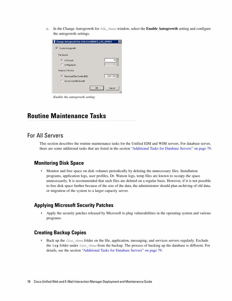
c. In the Change Autogrowth for File_Name window, select the Enable Autogrowth setting and configure the autogrowth settings.
Enable the autogrowth setting
Routine Maintenance Tasks
For All ServersThis section describes the routine maintenance tasks for the Unified EIM and WIM servers. For database server, there are some additional tasks that are listed in the section “Additional Tasks for Database Servers” on page 79.
Monitoring Disk Space Monitor and free space on disk volumes periodically by deleting the unnecessary files. Installation
programs, application logs, user profiles, Dr. Watson logs, temp files are known to occupy the space unnecessarily. It is recommended that such files are deleted on a regular basis. However, if it is not possible to free disk space further because of the size of the data, the administrator should plan archiving of old data, or migration of the system to a larger capacity server.
Applying Microsoft Security Patches Apply the security patches released by Microsoft to plug vulnerabilities in the operating system and various
programs.
Creating Backup Copies Back up the Cisco_Home folder on the file, application, messaging, and services servers regularly. Exclude
the log folder under Cisco_Home from the backup. The process of backing up the database is different. For details, see the section “Additional Tasks for Database Servers” on page 79.
78 Cisco Unified Web and E-Mail Interaction Manager Deployment and Maintenance Guide

Additional Tasks for Database ServersIn addition to the routine maintenance tasks that apply to all the Unified EIM and WIM servers, there are some special tasks for the database server that are described in this section.
Performing Disk Defragmentation Weekly defragmentation is recommended. Note that it requires downtime.
Monitoring Summarization Job RunsOn a weekly basis, verify that all the summarization jobs enabled for Unified EIM and WIM are running successfully at the scheduled times.
To view the summarization job run details:
1. In the Microsoft SQL Server Management Studio, browse to SQL Server Agent > Jobs.
2. In the jobs list, locate the job populatesmy_Database_Name. Where Database_Name is the name of the active database (in SQL Server Standard installations), or the reports database (in SQL Server Enterprise installations).
3. Right-click the populatesmy_Database_Name job and from the menu select View History.
4. In the Log File Viewer window, browse to Job History and check the following:
In the Date column, the date and time should not be very old as jobs run every 30 minutes.
For all successfully run jobs, the date column will show a green check mark.
Managing and Maintaining Servers 79
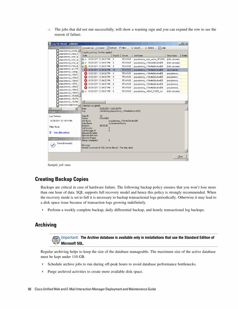
The jobs that did not run successfully, will show a warning sign and you can expand the row to see the reason of failure.
Sample job runs
Creating Backup CopiesBackups are critical in case of hardware failure. The following backup policy ensures that you won’t lose more than one hour of data. SQL supports full recovery model and hence this policy is strongly recommended. When the recovery mode is set to full it is necessary to backup transactional logs periodically. Otherwise it may lead to a disk space issue because of transaction logs growing indefinitely.
Perform a weekly complete backup, daily differential backup, and hourly transactional log backups.
Archiving
Regular archiving helps to keep the size of the database manageable. The maximum size of the active database must be kept under 110 GB.
Schedule archive jobs to run during off-peak hours to avoid database performance bottlenecks.
Purge archived activities to create more available disk space.
Important: The Archive database is available only in installations that use the Standard Edition of
Microsoft SQL.
80 Cisco Unified Web and E-Mail Interaction Manager Deployment and Maintenance Guide
Performance Tuning Considerations
One of the first steps towards tuning an application is to determine evolving requirements, which is not easy as requirements are likely to vary across different types of users. Administrators, typically, want the system to be easily configurable for various user loads, security needs, and application uptime. Business managers tend to care about issues such as security considerations for critical data that is passed between various components within the application, response times, reliability, availability, and scalability. For agents, response time is the most important factor that defines a finely tuned system.
Cisco Unified Web and E-Mail Interaction Manager Solutions Reference Network Design Guide helps to plan the configuration when you first set it up. In this section, we provide a quick overview of some of the factors that should be considered as the system grows.
Peak Concurrent UsageThe application will need to be tuned if there is a need to meet specific concurrent usage requirements. Concurrent usage includes usage by email and chat agents as well as chat sessions. The general guideline is that the greater the number of concurrent users, the likelier it is for the system to be stressed resulting in longer response times.
Email VolumeThe email volume that the application handles determines the amount of disk space used by the database, size of active and master databases, and the capacity of the database engine to provide optimal response times to data requests. Active usage of email attachments and Knowledge Base (KB) articles also affect disk space requirements.
Security RequirementsOften security requirements dictate that the application data should be accessed in a secure way. For this reason secure sockets layer (SSL) mode of access to information is set up. Likewise, sharing and access to critical information such as customer data require that data is stored and retrieved in a secure way by extra access control and beyond.
Additional security requirements do lead to some delay in response times for users accessing the application. This should be clearly understood by administrators setting up SSL mode of access on web servers or trying to access information stored on remote and highly secure resources like remotely mounted file systems or disks.
See Cisco Unified Web and E-Mail Interaction Manager Installation Guide for information about how to set up the SSL mode of communication on the web server.
Managing and Maintaining Servers 81

Modifying the Unified EIM
and WIM EAR
About the PackIt Utility
Configuring the Utility
How To
To make changes to the installation files, you must use the PackIt Utility. This chapter provides an overview on what this utility allows you to do, and how to use it.
About the PackIt Utility
Some of the changes in the product, like creating custom rules and conditions for workflows, require updating the EAR and some configuration and JAR files on the services server. The PackIt utility provides a user interface to make such changes to the files easily. Using this utility you can:
Add third party JARs in EAR for customizations.
Add schema and query files in the configuration_custom.zip file in the EAR.
Add or update custom classes in egpl_custom.jar.
Add new Java Data Adapter implementation classes in the EAR.
Add or update custom rules and conditions for workflows.
Add or update connection pool information for databases.
Configuring the Utility
Utility is available on the services server in the Cisco_Home\Utilities\egainpackit folder.
The ear should always be picked from the file server from the Cisco_Home\eService\installation\ear folder. Customers should make sure that the version on the file server is the latest one.
The utility can be run on any desktop. The desktop needs to have JDK 1.7 Update 2 or higher installed on the machine.
To configure the utility:
1. Copy the contents of the following folder from the services server on the machine where you want to run the utility: Cisco_Home\Utilities\egainpackit
Modifying the Unified EIM and WIM EAR 83
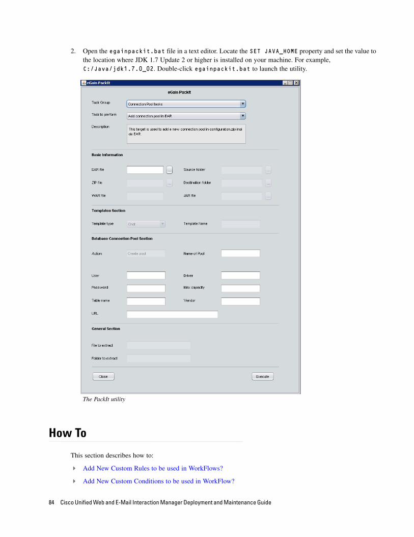
2. Open the egainpackit.bat file in a text editor. Locate the SET JAVA_HOME property and set the value to the location where JDK 1.7 Update 2 or higher is installed on your machine. For example, C:/Java/jdk1.7.0_02. Double-click egainpackit.bat to launch the utility.
The PackIt utility
How To
This section describes how to:
Add New Custom Rules to be used in WorkFlows?
Add New Custom Conditions to be used in WorkFlow?
84 Cisco Unified Web and E-Mail Interaction Manager Deployment and Maintenance Guide
Add New Connection Pools for SQL JDBC Data Adapters?
Update Connection Pools for SQL JDBC Data Adapters?
Remove a Redundant Connection Pool?
Extract Connection Pool File egpl_ds_connpool_map.xml From the EAR?
Extract a Template From the EAR?
Remove a Template From the EAR?
Add or Update a Template in the EAR?
Add Custom JARS Required for Customization?
Add New Custom Classes Required for Customization?
Add New Java Data Adapter Classes Required for Customization?
Add New Query and Schema Files Required for Customization?
Add New Custom Rules to be used in WorkFlows?
Changes on the Service Server
To add a new custom rule to egpl_custom.jar:
1. Copy the custom rules classes into a temporary folder on the machine.
2. Create a backup of Cisco_Home/eservice/lib/custom/egpl_custom.jar on the Services Server.
3. Start the PackIt utility.
4. From the Task Group menu, select WorkFlow tasks.
5. From the Task to perform menu, select Add custom rules for WorkFlow on Services Server.
6. Select the egpl_custom.jar that needs to be updated.
7. Select the source folder where the custom rule classes are located.
8. Click Execute to run PackIt.
9. This adds the new custom rules (with same package structure as in source folder) into the egpl_custom.jar.
10. An entry is be made for all custom rules in the egpl_custom.jar/METAINF/services/com.egain.platform.module.routing.CustomRule file.
Changes to the EARAs a best practice, maintain identical jars on the Services Server and in the EAR.
To add a new custom rule to the EAR:
1. Copy the folder with the custom rule classes to a temporary location.
Modifying the Unified EIM and WIM EAR 85

2. Create a backup of the EAR that is in the installation folder on the File Server.
3. Start the PackIt utility.
4. From the Task Group menu, select WorkFlow tasks.
5. From the Task to perform menu, select Add custom rules for WorkFlow in EAR.
6. Select the eService.ear that needs to be updated.
7. Select the source folder where the custom rule classes are located.
8. Click Execute to start PackIt.
9. This adds the new custom rules (with the same package structure as in the source folder) into egpl_custom.jar inside the EAR.
10. An entry is made for all the custom rules in eService.ear/lib/custom/egpl_custom.jar/META-INF/services/com.egain.platform.module.routing.CustomRule file.
Add New Custom Conditions to be used in WorkFlow?
Changes on the Service ServerTo add a new custom condition to egpl_custom.jar:
1. Copy the custom conditions classes into a temporary folder on the machine.
2. Create a backup of Cisco_Home/eservice/lib/custom/egpl_custom.jar on the Services Server.
3. Start the PackIt utility.
4. From the Task Group menu, select WorkFlow tasks.
5. From the Task to perform menu, select Add custom conditions for WorkFlow on Services Server.
6. Select the egpl_custom.jar that needs to be updated.
7. Select the source folder where the custom condition classes are located.
8. Click Execute to run PackIt.
9. This adds the new custom conditions (with the same package structure as in the source folder) into egpl_custom.jar.
10. An entry is made for all the custom conditions in egpl_custom.jar/META-INF/services/com.egain.platform.module.routing.CustomCondition file.
Changes to the EARAs a best practice, maintain identical jars on the Services Server and in the EAR.
To add a new custom condition to the EAR:
1. Copy the folder with the custom condition classes to a temporary location on the machine.
2. Create a backup of the EAR that is in the installation folder on the File Server.
3. Start the PackIt utility.
86 Cisco Unified Web and E-Mail Interaction Manager Deployment and Maintenance Guide

4. From the Task Group menu, select WorkFlow tasks.
5. From the Task to perform menu, select Add custom conditions for WorkFlow in EAR.
6. Select eServices.ear that needs to be updated.
7. Select the source folder where the custom condition classes are located.
8. Click Execute to run PackIt.
9. This adds the new custom conditions (with the same package structure as in the source folder) into egpl_custom.jar inside EAR.
10. An entry is made for all the custom conditions in eService.ear/lib/custom/egpl_custom.jar/META-
INF/services/com.egain.platform.module.routing.CustomCondition file.
Add New Connection Pools for SQL JDBC Data Adapters?
Changes to the EARTo add a new connection pool:
1. Create a backup of the EAR that is in the installation folder on the File Server.
2. Start the PackIt utility.
3. From the Task Group menu, select Connection Pool tasks.
4. From the Task to perform menu, select Add connection pool in EAR.
5. Select eServices.ear that needs to be updated.
6. Provide entries in the Database Connection Pool Section for each field. Please note only required fields are enabled on GUI so its important to provide correct value for the fields.
7. Click Execute to run PackIt.
8. This will add the new connection pool in egpl_ds_connpool_map.xml file in configurations.zip inside EAR.
Changes on the Service ServerTo add a new connection pool to configurations.zip:
1. Create a backup of Cisco_Home/eservice/lib/configurations.zip on Services Server.
2. Start the PackIt utility.
3. From the Task Group menu, select Connection Pool tasks.
4. From the Task to perform menu, select Add connection pool on Services Server.
5. Select the configurations.zip in the lib folder on the services server that needs to be updated.
6. Provide entries in Database Connection Pool Section for each field. Note that only required fields are enabled in the user interface, so its important to provide the correct values for the fields.
7. Click the Execute button to run PackIt.
Modifying the Unified EIM and WIM EAR 87
8. This adds the new connection pool in egpl_ds_connpool_map.xml file in configurations.zip.
Update Connection Pools for SQL JDBC Data Adapters?
Changes to the EAR
To update the connection pool:
1. Create a backup of the EAR that is in the installation folder on the File Server.
2. Start the PackIt utility.
3. From the Task Group menu, select Connection Pool tasks.
4. From the Task to perform menu, select Update connection pool in EAR.
5. Select the eServices.ear that needs to be updated.
6. Provide entries in the Database Connection Pool Section for each field. Note that only required fields are enabled in the user interface, so its important to provide the correct values for the fields.
7. Click the Execute button to run PackIt.
8. This updates the connection pool in egpl_ds_connpool_map.xml file in configurations.zip inside the EAR. If the pool does not exist in the file, it does not make any change.
Changes on the Service ServerTo update the connection pool in configurations.zip:
1. Create a backup of Cisco_Home/eservice/lib/configurations.zip.
2. Start the PackIt utility.
3. From the Task Group menu, select Connection Pool tasks.
4. From the Task to perform menu, select Update connection pool on Services Server.
5. Select the configurations.zip in the lib folder on the services server that needs to be updated.
6. Provide entries in the Database Connection Pool Section for each field. Note that only required fields are enabled in the user interface, so its important to provide the correct values for the fields.
7. Click the Execute button to run PackIt.
8. This updates the connection pool in egpl_ds_connpool_map.xml file in configurations.zip. If the pool does not exist in the file, it does not make any change.
88 Cisco Unified Web and E-Mail Interaction Manager Deployment and Maintenance Guide

Remove a Redundant Connection Pool?
Changes to the EAR
To remove a connection pool:
1. Create a backup of the EAR that is in the installation folder on the File Server.
2. Start the PackIt utility.
3. From the Task Group menu, select Connection Pool tasks.
4. From the Task to perform menu, select Remove connection pool in EAR.
5. Select the eServices.ear that needs to be updated.
6. Provide entries in Database Connection Pool Section for the name of pool that needs to be removed.
7. Click the Execute button to run PackIt.
8. This removes the connection pool in egpl_ds_connpool_map.xml file in configurations.zip inside the EAR. If the pool does not exist in the file, it does not make any change.
Changes on the Service Server
To remove a connection pool from configurations.zip:
1. Create a backup of Cisco_Home/eservice/lib/configurations.zip.
2. Start the PackIt utility.
3. From the Task Group menu, select Connection Pool tasks.
4. From the Task to perform menu, select Remove connection pool on Services Server.
5. Select the configurations.zip in the lib folder on the services server that needs to be updated.
6. Provide entries in Database Connection Pool Section for the name of the pool that needs to be removed.
7. Click the Execute button to run PackIt.
8. This removes the connection pool in egpl_ds_connpool_map.xml file in configurations.zip. If the pool does not exist in the file, it does not make any change.
Extract Connection Pool File egpl_ds_connpool_map.xml From the EAR?
To extract the egpl_ds_connpool_map.xml file:
1. Create a backup of the EAR that is in the installation folder on the File Server.
2. Start the PackIt utility.
3. From the Task Group menu, select Connection Pool tasks.
4. From the Task to perform menu, select Extract connection pool file from EAR.
5. Select the eServices.ear from where you need to extract the connection pool file.
Modifying the Unified EIM and WIM EAR 89

6. Provide the location of the destination folder to which you wish to extract the file.
7. Click the Execute button to run PackIt.
8. This extracts the egpl_ds_connpool_map.xml file from configuration.zip folder inside the EAR.
Extract a Template From the EAR?All old chat templates upgraded from previous versions of Unified EIM and WIM 9.0(1) are bundled in the chattemplates.WAR WAR file inside the EAR.
To extract a template from the EAR:
1. Create a backup of the EAR that is in the installation folder on the File Server.
2. Start the PackIt utility.
3. From the Task Group menu, select Template tasks.
4. From the Task to perform menu, select one of the following items.
To extract Chat templates, select Extract Chat templates from EAR
5. Select the eServices.ear from where you need to extract the selected templates.
6. Provide the name of the template that needs to be extracted.
7. Provide the location of the destination folder to which you wish to extract the templates.
8. Click the Execute button to run PackIt.
9. This extracts the selected template from inside EAR. If there is no template in the EAR with that name, nothing is extracted.
Remove a Template From the EAR?All old chat templates upgraded from previous versions of Unified EIM and WIM 9.0(1) are bundled in the chattemplates.WAR WAR file inside the EAR.
To remove a template from the EAR:
1. Create a backup of the EAR that is in the installation folder on the File Server.
2. Start the PackIt utility.
3. From the Task Group menu, select Template tasks.
4. From the Task to perform menu, select one of the following items.
To remove Chat templates, select Remove Chat templates from EAR
5. Select the eServices.ear from where you need to remove the selected templates.
6. Provide the name of the template that needs to be removed.
7. Click the Execute button to run PackIt.
8. This removes the selected template from inside the EAR. If there is no template in the EAR with that name, nothing is removed.
90 Cisco Unified Web and E-Mail Interaction Manager Deployment and Maintenance Guide
Add or Update a Template in the EAR?All old chat templates upgraded from previous versions of Unified EIM and WIM 9.0(1) are bundled in the chattemplates.WAR WAR file inside the EAR.
To add or update a template in the EAR:
1. Create a backup of the EAR that is in the installation folder on the File Server.
2. Start the PackIt utility.
3. From the Task Group menu, select Template tasks.
4. From the Task to perform menu, select Add or Update templates in EAR.
5. Select the eServices.ear from where you need to add or update templates.
6. Select the Template Type based on the product for which templates are being added or updated.
7. Select the name of the template that needs to be added or updated.
8. Select the source folder from where the new or updated templates are to be picked up.
9. Click the Execute button to run PackIt.
10. This adds the selected template to the correct WAR file inside the EAR.
Add Custom JARS Required for Customization?
Changes to the EARAny third-party JAR added for customization needs to go in lib/custom folder inside EAR. An entry for all those JARs are also made in MANIFEST.MF file of egpl_custom.jar so that they are added in classpath without needing to change any .bat files.
To add custom JARS to the EAR:
1. Create a backup of the EAR that is in the installation folder on the File Server.
2. Start the PackIt utility.
3. From the Task Group menu, select Miscellaneous tasks.
4. From the Task to perform menu, select Add custom jars in EAR.
5. Select the location of the EAR that needs to be updated
6. Select the source folder where the new JARs are located.
7. Click the Execute button to run PackIt.
8. This adds the new jars in lib/custom folder inside the EAR. It also makes an entry for all the JARs with the right path in MANIFEST.MF file of egpl_custom.jar file.
Modifying the Unified EIM and WIM EAR 91
Changes on the Service ServerAny third-party JAR added for customization needs to go in lib/custom folder inside EAR. An entry for all those JARs are also made in MANIFEST.MF file of egpl_custom.jar so that they are added in classpath without needing to change any .bat files.
To add custom JARS to egpl_custom.jar:
1. Create a backup of the Cisco_Home/eservice/lib/custom/egpl_custom.jar.
2. Start the PackIt utility.
3. From the Task Group menu, select Miscellaneous tasks.
4. From the Task to perform menu, select Add custom jars on Services Server.
5. Select the egpl_custom.jar file that needs to be updated.
6. Select the source folder where the new JARs are located.
7. Click the Execute button to run PackIt.
8. This adds the new jars into the Cisco_Home/eservice/lib/custom folder where egpl_custom.jar is located. It also makes an entry for all the JARs with the right path in MANIFEST.MF file of egpl_custom.jar file.
Add New Custom Classes Required for Customization?
Changes to the EARAny new custom classes need to go in the /lib/custom/egpl_custom.jar inside the EAR.
To add custom classes to the EAR:
1. Create a backup of the EAR that is in the installation folder on the File Server.
2. Start the PackIt utility.
3. From the Task Group menu, select Miscellaneous tasks.
4. From the Task to perform menu, select Bundle custom classes inside EAR.
5. Select the location of the EAR that needs to be updated.
6. Select the source folder where the new classes are located.
7. Click the Execute button to run PackIt.
8. This adds the new classes in lib/custom/egpl_custom.jar inside the EAR.
92 Cisco Unified Web and E-Mail Interaction Manager Deployment and Maintenance Guide
Changes on the Service ServerAny new custom classes need to go in the /lib/custom/egpl_custom.jar on Services Server.
To add custom classes to egpl_custom.jar:
1. Create a backup of egpl_custom.jar on the Services Server.
2. Start the PackIt utility.
3. From the Task Group menu, select Miscellaneous tasks.
4. From the Task to perform menu, select Bundle custom classes on Services Server.
5. Select the location of the egpl_custom.jar that needs to be updated.
6. Select the source folder where the new classes are located.
7. Click the Execute button to run PackIt.
8. This adds the new classes in lib/custom/egpl_custom.jar on the Services Server.
Add New Java Data Adapter Classes Required for Customization?
Changes to the EARAny new custom classes need to go in the /lib/custom/egpl_custom.jar inside the EAR.
To add Java data adapter classes to the EAR:
1. Create a backup of the EAR that is in the installation folder on the File Server.
2. Start the PackIt utility.
3. From the Task Group menu, select Miscellaneous tasks.
4. From the Task to perform menu, select Bundle custom classes inside EAR.
5. Select the location of the EAR that needs to be updated.
6. Select the source folder where the new classes are located.
7. Click the Execute button to run PackIt.
8. This adds the new Java Data Adapter classes in lib/custom/egpl_custom.jar inside the EAR.
Changes on the Service ServerAny new custom classes need to go in the /lib/custom/egpl_custom.jar on Services Server.
To add Java data adapter classes to egpl_custom.jar:
1. Create a backup of egpl_custom.jar on the Services Server.
2. Start the PackIt utility.
3. From the Task Group menu, select Miscellaneous tasks.
Modifying the Unified EIM and WIM EAR 93
4. From the Task to perform menu, select Bundle custom classes on Services Server.
5. Select the location of the egpl_custom.jar that needs to be updated.
6. Select the source folder where the new classes are located.
7. Click the Execute button to run PackIt.
8. This adds the new Java Data Adapter classes in lib/custom/egpl_custom.jar on the Services Server.
Add New Query and Schema Files Required for Customization?
Changes to the EARAny new custom classes need to go in the configurations_custom.zip inside the EAR.
To add new query and schema files to the EAR:
1. Create a backup of the EAR that is in the installation folder on the File Server.
2. Start the PackIt utility.
3. From the Task Group menu, select Miscellaneous tasks.
4. From the Task to perform menu, select Bundle custom schema or query files inside EAR.
5. Select the location of the EAR that needs to be updated.
6. Select the source folder where the new schema or query files are located.
7. Click the Execute button to run PackIt.
8. This adds the new files to configurations_custom.zip inside the EAR.
Changes on the Service ServerAny new custom classes need to go in the configurations_custom.zip on Services Server.
To add new query and schema files to egpl_custom.jar:
1. Create a backup of egpl_custom.jar on the Services Server.
2. Start the PackIt utility.
3. From the Task Group menu, select Miscellaneous tasks.
4. From the Task to perform menu, select Bundle custom schema or query files on Services Server.
5. Select the location of the egpl_custom.jar that needs to be updated.
6. Select the source folder where the new schema or query files are located.
7. Click the Execute button to run PackIt.
8. This adds the new files to configurations_custom.zip on the Services Server.
94 Cisco Unified Web and E-Mail Interaction Manager Deployment and Maintenance Guide