cisco telepresence mx800 single floor stand installation sheet · mark the required screw hole ......
TRANSCRIPT

78-100219-02A0 | JUNE 2016 | © 2016 Cisco Systems, Inc. All rights reserved. http://www.cisco.com/go/mx-docs
Installation guidefor Cisco TelePresence MX800 Single Monitor with Single/Dual Camera
on a free standing floor stand or a floor stand secured to the wall
Installation guide for Cisco TelePresence MX800 - Floor stand
78-100219-02A0 | JUNE 2016 | © 2016 Cisco Systems, Inc. All rights reserved. Page 2 http://www.cisco.com/go/mx-docs
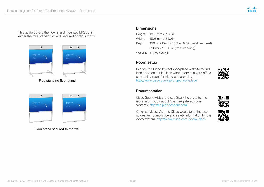
This guide covers the floor stand mounted MX800, in either the free standing or wall secured configurations.
Free standing floor stand
Floor stand secured to the wall
DimensionsHeight: 1818 mm / 71.6 in.Width: 1596 mm / 62.9 in.Depth: 156 or 215 mm / 6.2 or 8.5 in. (wall secured) 920 mm / 36.3 in. (free standing)Weight: 115 kg / 254 lb
Room setup
Explore the Cisco Project Workplace website to find inspiration and guidelines when preparing your office or meeting room for video conferencing, http://www.cisco.com/go/projectworkplace
Documentation
Cisco Spark: Visit the Cisco Spark help site to find more information about Spark registered room systems, http://help.ciscospark.com
Other services: Visit the Cisco web site to find user guides and compliance and safety information for the video system, http://www.cisco.com/go/mx-docs
Installation guide for Cisco TelePresence MX800 - Floor stand
78-100219-02A0 | JUNE 2016 | © 2016 Cisco Systems, Inc. All rights reserved. Page 3 http://www.cisco.com/go/mx-docs
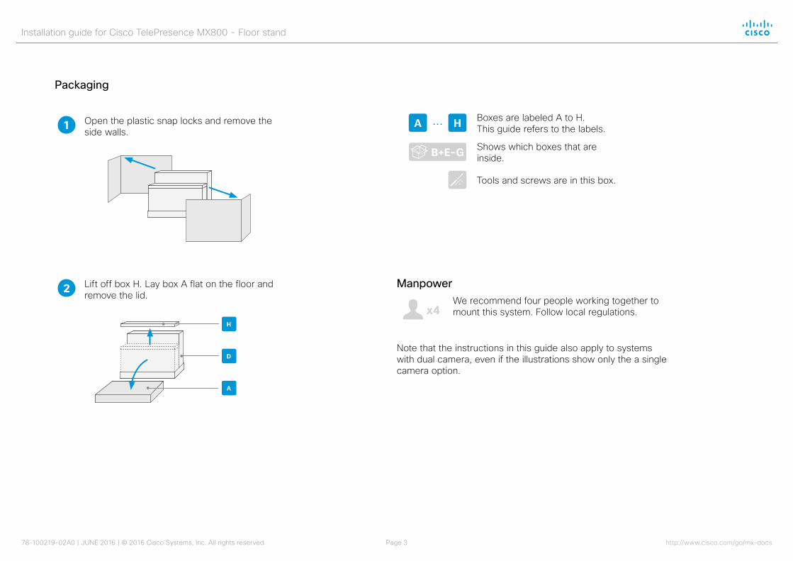
Lift off box H. Lay box A flat on the floor and remove the lid.
2
1 Open the plastic snap locks and remove the side walls.
Packaging
H
A
D
Boxes are labeled A to H. This guide refers to the labels.A H...
B+E-G Shows which boxes that are inside.
Tools and screws are in this box.
ManpowerWe recommend four people working together to mount this system. Follow local regulations.
Note that the instructions in this guide also apply to systems with dual camera, even if the illustrations show only the a single camera option.
4
Installation guide for Cisco TelePresence MX800 - Floor stand
78-100219-02A0 | JUNE 2016 | © 2016 Cisco Systems, Inc. All rights reserved. Page 4 http://www.cisco.com/go/mx-docs
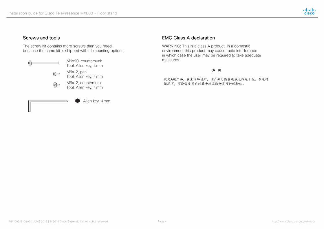
Screws and tools
The screw kit contains more screws than you need, because the same kit is shipped with all mounting options.
M6x90, countersunk Tool: Allen key, 4 mm
M6x12, countersunk Tool: Allen key, 4 mm
Allen key, 4 mm
M6x12, pan Tool: Allen key, 4 mm
EMC Class A declaration
WARNING: This is a class A product. In a domestic environment this product may cause radio interference in which case the user may be required to take adequate measures.
声 明 此为A级产品,在生活环境中,该产品可能会造成无线电干扰。在这种情况下,可能需要用户对其干扰采取切实可行的措施。
WARNING: This is a class A product. In a domestic environment this product may cause radio interference in which case the user may be required to take adequate measures.
Installation guide for Cisco TelePresence MX800 - Floor stand
78-100219-02A0 | JUNE 2016 | © 2016 Cisco Systems, Inc. All rights reserved. Page 5 http://www.cisco.com/go/mx-docs
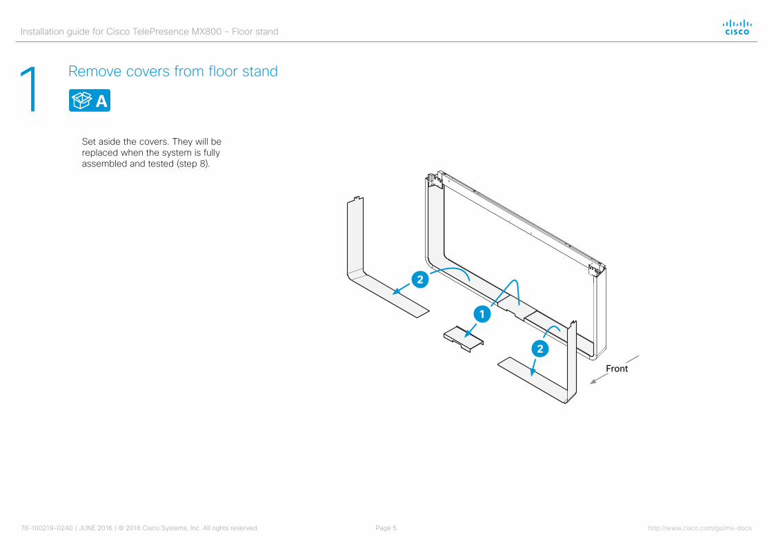
1 Remove covers from floor stand
Set aside the covers. They will be replaced when the system is fully assembled and tested (step 8).
2
1
2
Front
A

Installation guide for Cisco TelePresence MX800 - Floor stand
78-100219-02A0 | JUNE 2016 | © 2016 Cisco Systems, Inc. All rights reserved. Page 6 http://www.cisco.com/go/mx-docs
2 Secure floor stand Option A: Mount the feet to the floor stand to allow it to be free standing
B, C
Front
4 × M6x35, countersunk
Option B (secured to the wall) is described on the next page.

Installation guide for Cisco TelePresence MX800 - Floor stand
78-100219-02A0 | JUNE 2016 | © 2016 Cisco Systems, Inc. All rights reserved. Page 7 http://www.cisco.com/go/mx-docs
2 Secure floor stand
The system must be installed by qualified personnel, in accordance with state and local building regulations.
The wall and mounting hardware must be able to safely support the product.
2 Place the floor stand in the wall bracket and move the floor stand with the wall bracket into position. Mark the required screw hole positions on the wall.
The wall bracket can be fastened through any of the horizontal slots.
Fasten the bracket in a secure manner ensuring that the wall’s structure is sufficient to support the system (screws/mounting hardware not provided; not shown in illustration).
B, G
Front
3 Fasten the floor stand to the wall bracket with the two screws (provided).
2 × M6x12, pan
Option B: Use the wall bracket provided to secure the floor stand to the wall
Option A (free standing with feet) is described on the previous page.
The wall bracket has two mounting options. Position the bracket the way that suits your room the best.
1
Side view
94 mm / 3.7 in. 37 mm / 1.5 in.
Side view
Installation guide for Cisco TelePresence MX800 - Floor stand
78-100219-02A0 | JUNE 2016 | © 2016 Cisco Systems, Inc. All rights reserved. Page 8 http://www.cisco.com/go/mx-docs
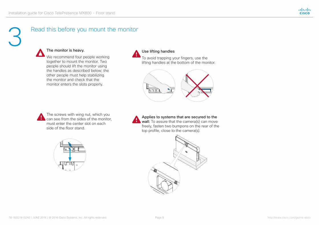
3 Read this before you mount the monitor
The screws with wing nut, which you can see from the sides of the monitor, must enter the center slot on each side of the floor stand.
Applies to systems that are secured to the wall: To assure that the camera(s) can move freely, fasten two bumpons on the rear of the top profile, close to the camera(s).
Use lifting handles
To avoid trapping your fingers, use the lifting handles at the bottom of the monitor.
The monitor is heavy.
We recommend four people working together to mount the monitor. Two people should lift the monitor using the handles as described below; the other people must help stabilizing the monitor and check that the monitor enters the slots properly.
Installation guide for Cisco TelePresence MX800 - Floor stand
78-100219-02A0 | JUNE 2016 | © 2016 Cisco Systems, Inc. All rights reserved. Page 9 http://www.cisco.com/go/mx-docs
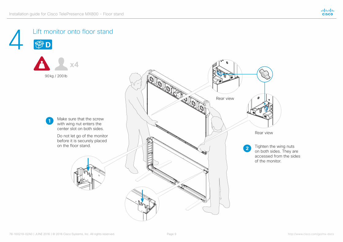
4 Lift monitor onto floor stand
D
90 kg / 200 lb
4
Make sure that the screw with wing nut enters the center slot on both sides.
Do not let go of the monitor before it is securely placed on the floor stand.
1
Tighten the wing nuts on both sides. They are accessed from the sides of the monitor.
2
Rear view
Rear view

Installation guide for Cisco TelePresence MX800 - Floor stand
78-100219-02A0 | JUNE 2016 | © 2016 Cisco Systems, Inc. All rights reserved. Page 10 http://www.cisco.com/go/mx-docs
5 Fasten monitor to floor stand
Enter four screws from front and four screws from underneath. Then, tighten all screws.
4 × M6x90, countersunk
4 × M6x12, countersunk
Installation guide for Cisco TelePresence MX800 - Floor stand
78-100219-02A0 | JUNE 2016 | © 2016 Cisco Systems, Inc. All rights reserved. Page 11 http://www.cisco.com/go/mx-docs
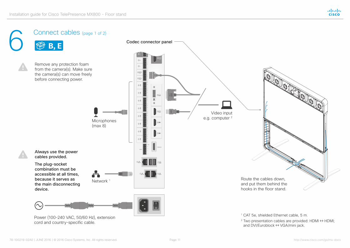
6 Connect cables
B, E
Network 1
Microphones (max 8)
Power (100-240 VAC, 50/60 Hz), extension cord and country-specific cable.
Video input e.g. computer 2
Route the cables down, and put them behind the hooks in the floor stand.
Remove any protection foam from the camera(s). Make sure the camera(s) can move freely before connecting power.
1 CAT 5e, shielded Ethernet cable, 5 m.2 Two presentation cables are provided: HDMI ↔ HDMI;
and DVI/Euroblock ↔ VGA/mini jack.
Always use the power cables provided.
The plug-socket combination must be accessible at all times, because it serves as the main disconnecting device.
(page 1 of 2)
Codec connector panel
Installation guide for Cisco TelePresence MX800 - Floor stand
78-100219-02A0 | JUNE 2016 | © 2016 Cisco Systems, Inc. All rights reserved. Page 12 http://www.cisco.com/go/mx-docs
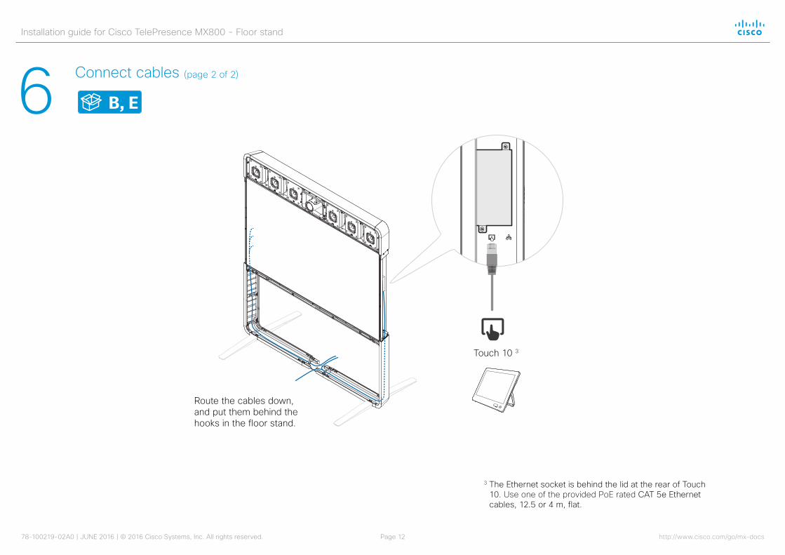
6 Connect cables
B, E
Route the cables down, and put them behind the hooks in the floor stand.
Touch 10 3
3 The Ethernet socket is behind the lid at the rear of Touch 10. Use one of the provided PoE rated CAT 5e Ethernet cables, 12.5 or 4 m, flat.
(page 2 of 2)
Installation guide for Cisco TelePresence MX800 - Floor stand
78-100219-02A0 | JUNE 2016 | © 2016 Cisco Systems, Inc. All rights reserved. Page 13 http://www.cisco.com/go/mx-docs
7 Start up the system
• Remove the protection foil from the display.
• Make sure the camera(s) can move freely.
• Insert the network and power cables into the wall outlets.
• Switch on the system.
The power switch is located directly below the codec, next to the power connector.
Wait a few minutes while the system starts up. The start-up may include automatic software upgrade and restart of Touch 10 and camera(s).
• Follow the instructions on the Touch controller.
Cisco Spark: To find more information on how to get started with Spark registered systems, visit http://help.ciscospark.com and look for Getting Started articles for room systems.
Other services: For further information on set-up and configuration, download the Getting Started Guide from the Cisco web site, http://www.cisco.com/go/mx-docs

Installation guide for Cisco TelePresence MX800 - Floor stand
78-100219-02A0 | JUNE 2016 | © 2016 Cisco Systems, Inc. All rights reserved. Page 14 http://www.cisco.com/go/mx-docs
8 Mount covers
F
The covers snap to magnets.
2
3
3
1
1
Installation guide for Cisco TelePresence MX800 - Floor stand
78-100219-02A0 | JUNE 2016 | © 2016 Cisco Systems, Inc. All rights reserved. Page 15 http://www.cisco.com/go/mx-docs
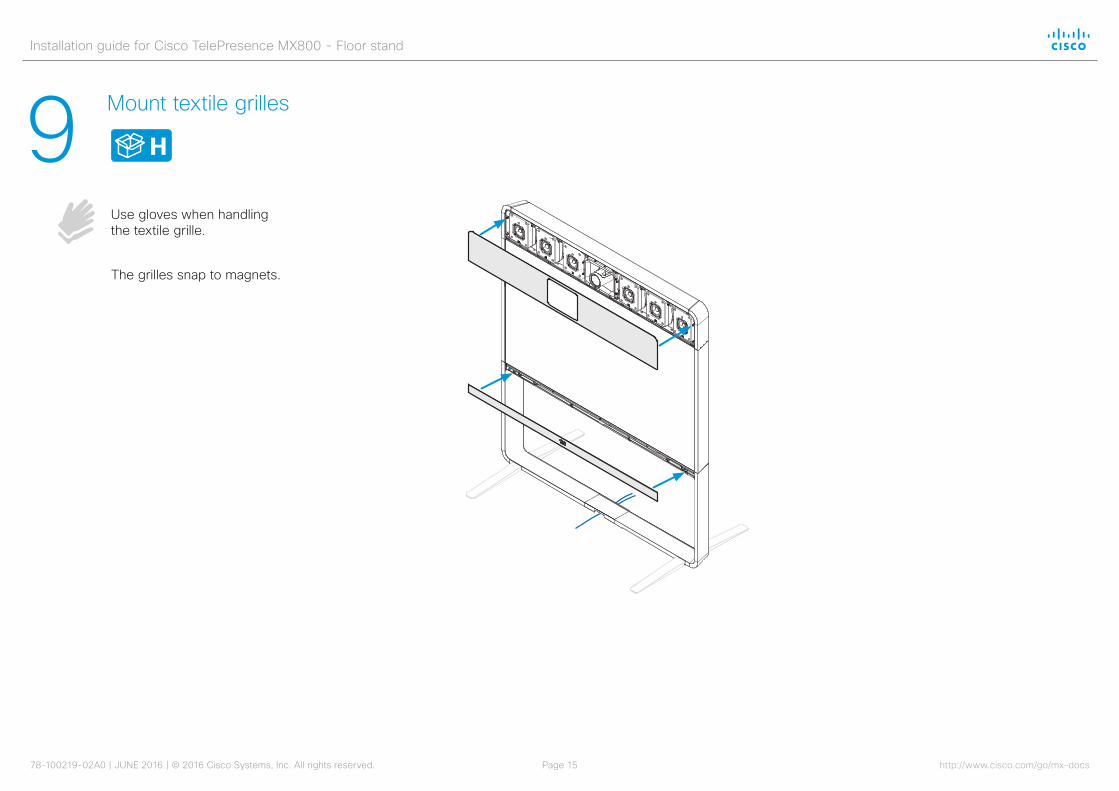
9 Mount textile grilles
Use gloves when handling the textile grille.
H
The grilles snap to magnets.
Installation guide for Cisco TelePresence MX800 - Floor stand
78-100219-02A0 | JUNE 2016 | © 2016 Cisco Systems, Inc. All rights reserved. Page 16 http://www.cisco.com/go/mx-docs
For a list of offices, visit the Cisco website at http://www.cisco.com/go/offices
Cisco and the Cisco logo are trademarks or registered trademarks of Cisco and/or its affiliates in the U.S. and other countries. To view a list of Cisco trademarks, go to this URL: www.cisco.com/go/trademarks. Third-party trademarks mentioned are the property of their respective owners. The use of the word partner does not imply a partnership relationship between Cisco and any other company. (1110R)