cisco telepresence dx, mx, sx, and room series and webex ......touch10. our touch-based control...
TRANSCRIPT

1
D1535814 CE Customization Guide. Produced October 2019 for CE9.9 and RoomOS. Copyright © 2015–2019 Cisco Systems, Inc. All rights reservedD1535814 CE Customization Guide. Produced October 2019 for CE9.9 and RoomOS. Copyright © 2015–2019 Cisco Systems, Inc. All rights reserved
CE CustomizationUser Interface Extensions and Macros CE 9.9 and RoomOS
With CE Customization you can add custom elements to your Touch10 operated video systems, your DX Series as well as Webex Board user interfaces.
Such user interface extensions may be in-room controls for lights, for curtains or for other peripherals (including one or more video switches to extend the number of video sources available). The interface extensions will then communicate with external control systems to let you obtain the functionality you want.
Macros allow you to write snippets of JavaScript code that can automate parts of your video endpoint behavior.
The fact that the Cisco video system itself and peripherals now can be controlled from the Touch10 and DX Series as well as Webex Boards user interfaces helps providing a consistent user experience throughout the meeting room.
The current version of the CE Customization utility is available for the SX, MX, DX, Room Series Webex Board systems running Collaboration Endpoint Software, software version CE 9.9 and for systems running RoomOS.
Note that macros in the SX10 are not supported.

2
D1535814 CE Customization Guide. Produced October 2019 for CE9.9 and RoomOS. Copyright © 2015–2019 Cisco Systems, Inc. All rights reserved
What’s In This Document
Part 1
Introducing Control Panel ExtensionsDefinition of Terms ....................................................................................... 4About the Possibilities .................................................................................. 5
Creating a Control Panel ExtensionIntroduction .................................................................................................. 7Launching the Editor .................................................................................... 8A Tour of the Panel EditorREVISED .................................................................... 9Previewing Your Current Configuration ......................................................10
Application Programming Interface (API)API for Programming In-Room Controls ....................................................12
WidgetsOverview of Widgets ..................................................................................17Switch ........................................................................................................18Slider ..........................................................................................................19Button .........................................................................................................20Group Button ..............................................................................................21Icon Button .................................................................................................22Spinner .......................................................................................................23Text ............................................................................................................24Directional Pad ...........................................................................................25Spacer ........................................................................................................26
Removing Default ButtonsRemoving Default Buttons ..........................................................................28An Out-of-Call Example ............................................................................29An In-Call Example ....................................................................................30
Command ReferenceEvents ........................................................................................................32Commands.................................................................................................34Statuses .....................................................................................................35
Creating Interactive MessagesHow Interactive Messages Work ................................................................37
HTTP(S) RequestsSending HTTP(S) Requests .......................................................................40
TroubleshootingTips When Troubleshooting .......................................................................42
Tips and TricksRecommended Best Practice ....................................................................44Granting Access to the UI Extensions Editor and the Extensions API ........46
Creating WebAppsNEW
WebApp Extensions ...................................................................................48
Part 2
Use of a Video SwitchUsing a Third-party Video Switch to Extend the Number of Video Sources Available ..........................................................50Command Details .......................................................................................51Video Switch Example ...............................................................................52
Part 3
Working with MacrosCreating Macros .........................................................................................54The Macro Editor Panel ..............................................................................55Things to Observe ......................................................................................56
Part 4
Incorporating Third-party USB Control DevicesAbout the USB Control Device Functionality ..............................................58Example on the Use of a Third-Party USB Input Device ............................59
Part 5
Audio ConsoleCustomizing the Audio Connections ..........................................................61The Audio Console Panel ...........................................................................62Setting Up the Equalizer .............................................................................63More On Setting Up the Microphones .......................................................64
On the Use of This GuideWhen reading this document on javascript enabled devices, the entries in the table of contents are all hyperlinks. You can click on them to go to the topic.
Product DocumentationUser guides, compliance and safety information for Cisco TelePresence systems are available at https://www.cisco.com/go/telepresence/docs
For Cisco Webex registered devices, go to https://help.webex.com
Specific links to other guides:https://www.cisco.com/go/sx-docs https://www.cisco.com/go/mx-docs https://www.cisco.com/go/dx-docs https://www.cisco.com/go/room-docs https://www.cisco.com/go/board-docs
Cloud registered devices: https://help.webex.com
We recommend that you visit the Cisco web site regularly for updated versions of this guide.
Who Has Access to the Editor?In order to access the editor you will need to have administrator rights.However, an administrator may create a User account. With this account it is possible to log into the codec to run the Editor. No other part of the web interface is accessible from this account.If you use SSH to log into the codec, only a very limited set of the API will be accessible.

3
D1535814 CE Customization Guide. Produced October 2019 for CE9.9 and RoomOS. Copyright © 2015–2019 Cisco Systems, Inc. All rights reserved
Part 1Introducing Control Panel Extensions
4
D1535814 CE Customization Guide. Produced October 2019 for CE9.9 and RoomOS. Copyright © 2015–2019 Cisco Systems, Inc. All rights reserved
With the Control Panel part of the UI Extensions Editor you can add custom elements to our Touch10 / DX / Webex Board user interfaces. Such user interface extensions may be controls for lights or blinds, or other peripherals (including one or more video switches to extend the number of video sources available) all controlled by external control systems.
Since both the Cisco video system and the other peripherals now are controlled from the systems’ user interfaces, you will get a consistent user experience throughout the meeting room.
The version of the UI Extensions Editor described in this document, is available for the MX, SX (macros not for SX10) and DX Series video systems running Collaboration Endpoint Software, version CE9.9 or later, as well as for systems running RoomOS.
Definition of TermsPart 1: Introducing Control Panel Extensions
What Is In-Room Control?
The following terms will be used throughout this document:
Video system. Video system or codec in the Cisco TelePresence MX Series, SX, DX Series and Webex Board running Collaboration Endpoint Software, version CE9.8 or later, as well as systems running RoomOS. Sometimes all these referred to as video devices. Newer versions of the the CE software will be required to achieve full functionality for future versions.
Control system. Third-party control system with hardware drivers for peripherals, for example Crestron, AMX, Raspberry Pi.
Touch10. Our touch-based control device for the MX Series and SX Series video systems. Full product name: Cisco TelePresence Touch10. Also known as Touch10 controller, Touch10 user interface or Touch10 panel.
Control panels. Panel with controls for third-party peripherals in the room. The panel opens when you tap the corresponding control icon in the status bar on Touch10. See the Create a user interface chapter for more on this.
Control panel editor. Our easy to use drag-and-drop editor for making control panels.
xAPI. The bidirectional API of the video system. The xAPI
allows third-party applications to interface with and interact with the video system, and vice versa.
Widget. User interface element, for example buttons, sliders, and text fields, that you can use to build an in-room control panel for Touch10.

5
D1535814 CE Customization Guide. Produced October 2019 for CE9.9 and RoomOS. Copyright © 2015–2019 Cisco Systems, Inc. All rights reserved
To utilize the features of the Control Panel Extensions you will need a Cisco video system with a Touch10 / DX / Webex Board user interface, and a third-party control system, for example Crestron, AMX.
The video system’s API, referred to as the xAPI, is the link between the video system and the control system. Use the events and commands exposed by the xAPI when you program the control system.
The simple drag-and-drop editor offers a library of user interface elements, referred to as widgets. You can use these widgets to create your own control panel for the Touch10 / DX Webex Board user interface.
Together, all of this provides a powerful combination of the control system’s functionality and the user-friendly Touch10 / DX / Webex Board user interface.
Note! All examples in this document show Touch10 user cases only, but this should not cause major difficulties due to the high degree of similarity between the interfaces.
About the PossibilitiesHow the Control Panel Extension Works
You can customize the Touch10 / DX / Webex Board user interface to allow control of peripherals in a meeting room, for example playback of a sound or movie source, lights and blinds.
You can also add content sensitive controls appearing only when in a call and/or only outside calls.
Although the maximum number of panels is unlimited, observe that for all practical purposes the maximum number of panels will be set by usability requirements and, to some extent, the system resources.
Each button you introduce on the Touch10 / DX / Webex Board will need a corresponding panel unless you opt for applications like speed dialing and one button to push.
If there is not enough space left on the screen, a More... button will appear to provide access to the rest of the buttons.
This means that altogether you have three sets of panels at your disposal:
• Always icons (buttons), visible at all times.
• Outside calls only icons (buttons), visible outside calls only.
• In-Call only icons (buttons), visible during calls only.
Video system
Blinds
Climate
Lights
Other...
Control Panel Editor
xAPI
Control system
Touch10
Examples of how customization made by means of the Control Panel Editor may appear on the Touch10, with an icon as shown at left and the menu appearing when that icon has been tapped, allowing control of music player, as shown at right.
Control schematics using Touch10 as example.
Part 1: Introducing Control Panel Extensions

6
D1535814 CE Customization Guide. Produced October 2019 for CE9.9 and RoomOS. Copyright © 2015–2019 Cisco Systems, Inc. All rights reserved
Creating a Control Panel Extension

7
D1535814 CE Customization Guide. Produced October 2019 for CE9.9 and RoomOS. Copyright © 2015–2019 Cisco Systems, Inc. All rights reserved
The editor that you launch from the video system’s web interface and the offline editor share the same file format, so files created in one version can be opened and modified in the other.
IntroductionPart 1: Creating a Control Panel Extension
Shared file format
Use the Control Panel Editor to create customized panels for peripheral controls on the video system’s Touch10 / DX / Webex Board user interface.
Connected to the Video System
If you have access to the video system, you can launch the editor from the video system’s web interface.
If a control panel already has been created on the system, this will automatically load into the editor, ready to act as a starting point for your design.
When you push a new panel to the video system, you will immediately see the result on the Touch10 / DX / Webex Board screen.
OfflineThere are two places you can download the offline editor from:
• Download from http://www.cisco.com/go/in-room-control-docs
• From the codec itself, as shown on the next page.
If you choose to download the offline editor, extract the files from the downloaded zip-file. Retain the folder structure.
When using the offline editor you will be working with files, rather than communicating directly with the video system. Apart from this, the offline editor has full functionality.
Offline In-Room Control Editor
Export new In-Room control
panel to file
Import an In-Room control panel from file
Offline In-Room Control Editor
Control Panel Editor launched from the video system's web interface
Push new control panel to video system
Import existing control panel from video system
Export new control panel to
file
Import a control panel from file
Video system
Touch10
Control Panel Editor

8
D1535814 CE Customization Guide. Produced October 2019 for CE9.9 and RoomOS. Copyright © 2015–2019 Cisco Systems, Inc. All rights reserved
Launching the Editor
Sign in to the video system’s web interface with administrator credentials, navigate to Integration and click on UI Extensions Editor. Click New.
If this is not the first time you add extensions, already existing extensions will be displayed, as shown at low right.
Panel or Action? You will now be provided with the option to create a panel with buttons and sliders or to create an action button, which just does something when pushing it. An action will not need a panel.
An example of a panel could be a light dimmer control and an example an action button could be a speed dial button.
Creating Action buttons. Such buttons starts running a custom script (a macro). You need to either write a script yourself or tweak an existing example. Read more about macros in “Working with Macros” on page 53.
WebApps. You may also create a WebApp extension which will launch a web view in full screen on the main monitor. To add a WebApp button requires Web Engine to have been enabled.
WebApps can be used on Webex Board units only. WebApps are available outside calls only.
More on WebApps is found in “WebApp Extensions” on page 48.
Off-line version of the Editor. If you need to use the off-line version of the Editor, just download it from the menu as shown at upper far right.
Part 1: Creating a Control Panel Extension
Already existing extensions will be
shown like this. To edit an existing
extension, just click on its name.
If you need to work off-line, the Editor can be downloaded from here

9
D1535814 CE Customization Guide. Produced October 2019 for CE9.9 and RoomOS. Copyright © 2015–2019 Cisco Systems, Inc. All rights reserved
A Tour of the Panel EditorPart 1: Creating a Control Panel Extension
Access Page properties by clicking here
Double-click on a text field to edit it. Click
Enter when done before proceeding
More options
Preview current configuration
These are the widgets available — see the chapter “Widgets” on page 16
for more
Upload configuration to codec
Undo and redo
Use the arrow keys of the Position (in Properties) to shift the position of a specific panel in the sequence up or down. This will determine the order, in which the buttons appear on the screen
The maximum number of panels has now been increased to 20. A practical limit will be set by usability and, to some extent, the system resources. Each button you introduce on the Touch10 / DX / Webex Board will need a corresponding panel. A panel will belong to one of the three following groups:• In-call only (visible during calls only) • Outside calls only (visible outside calls only) • Always (visible at all times)
If you create more buttons than the Touch10 / DX / Webex Board can accommodate, a button called More will be created to give access to the excess buttons.
Boards only: To produce In-call only buttons on the board during a call, tap the screen. To produce Always buttons during a call, tap the Home button.
DX only: Tap the screen during a call to produce the buttons.
Control panels can be arranged in pages. Each page consists of one or more rows, which you can populate with text and user interface elements known as widgets.
The maximum number of pages per panel is 50.
Widgets are arranged in a four-column grid. The widgets are placed into the grid according to the following rules:
• A widget fills between one and four columns depending on its size.
• Rows are right-aligned.
• If you add more widgets than fit in one line, widgets wrap to a new line within the same row.
Add new line here Add new page here
The properties panel will then show properties of the selected widget
Specify when the panel shall be available
Use these to change the order of the panels, see more about this in the text at top left
The icon chosen here will be the one that appears on the In-Room Control button for that panel on the screen
The panel ID
The panel name
You may specify the color of a UI Extension button appearing on the screen (see main panel at left for examples). A limited color palette used for standard buttons is available in the editor. When you select a color, a small description of the context in which this color is used by Cisco, will be provided, as shown
Panel properties
The properties panel will display settings for any part selected/highlighted by the yellow frame. Such a selection can be Panel, Page, Row or Widget (as shown here)
Entire sets of panels, or just a single panel can be exported to file for later use
When importing from file, choose between Import and Merge. Merge will append panels to current set of panels. Any panels with the same name will then be overwritten
Create new panel here

10
D1535814 CE Customization Guide. Produced October 2019 for CE9.9 and RoomOS. Copyright © 2015–2019 Cisco Systems, Inc. All rights reserved
Previewing Your Current Configuration
Click here to start the preview.
Click here to return to the previous view.
The above provides a simulated view of your configuration, with a simulated third-party control system connected.
When implementing your configurations (a real situation scenario), make sure your control system has been set to send SetValue commands wherever applicable.
Example: If you set Lights to On in a real situation scenario, the Touch10 needs to receive feedback confirming that the lights actually are switched on. For this to take place, the controller must switch on the lights and then send a SetValue, confirming the change of the lights settings. The right pane of the above example shows a simulation of what the Touch10 sends to the Control system and what the Control system then sends back to the Touch10.
In a real situation scenario, you should also make sure that the control system sends a SetValue to the Touch10 whenever someone operates the light switch on the wall in the meeting room.
This pane shows the flow of information between a (simulated) control system and the Touch10.
You may preview your configurations to verify them before deploying them.
Click the widgets to see the effect of your design.
Note! The preview works for Touch10, DX and Webex Boards, but it will look it as if all of it has been created for a Touch10.
Part 1: Creating a Control Panel Extension

11
D1535814 CE Customization Guide. Produced October 2019 for CE9.9 and RoomOS. Copyright © 2015–2019 Cisco Systems, Inc. All rights reserved
Application Programming Interface (API)

12
D1535814 CE Customization Guide. Produced October 2019 for CE9.9 and RoomOS. Copyright © 2015–2019 Cisco Systems, Inc. All rights reserved
API for Programming In-Room Controls
Connect to the Video SystemThe video system’s API (also known as the xAPI) allows bidirectional communication with third-party control systems, such as those from AMX or Crestron. There are multiple ways to access the xAPI:
• Telnet• SSH• HTTP/HTTPS• RS-232 / serial connection
Regardless of the method you choose, the structure of the xAPI is the same. Choose the access method that suits your application and video system the best.
Consult the API guide for your video system to get a full description of available access methods and how to use the xAPI.
Go to: http://www.cisco.com/go/sx-docs for SX Series http://www.cisco.com/go/mx-docs for MX Series http://www.cisco.com/go/dx-docs for DX Series
Then, click Reference Guides > Command References to find the API guides.
Communicate over the APIThe video system and the control system exchange messages through the xAPI to make sure that the Touch10 / DX Control panel always reflects the actual status of the room.
The video system sends one or more events when someone uses one of the controls on the Touch10 / DX Control panel, and the control system should send a command to the video system when there is a change in the room settings.
Video system
xAPI
Control system
Touch 10
Commands
Events
The video system and the control system exchange messages through the xAPI.
Examples:
• When someone taps a Lights On button on Touch10 / DX, the video system sends the associated events. The control system should respond to these events by switching on the lights in the room and send the corresponding command back to the video system.
• When someone switches on the lights in the room, the control system should send a command to the video system, so that the video system can update the Touch10 / DX Control panel to reflect that the light is on.
See the Command reference chapter for an overview of all relevant events, commands and statuses for in-room control.
Pairing Video System and Control SystemYou can register the control system as a peripheral connected to the video system:
xCommand Peripherals Connect ID: “ID” Type: ControlSystem
where ID is the unique ID for the control system, typically the MAC address.
See the API guide for more details about this command, and its options.
Heartbeats. The control system must send heartbeats to the video system to let the video system know that the control system is connected. The control system stays on the connected devices list (refer to xStatus Peripherals ConnectedDevice) as long as the video system receives these heartbeats from the control system.
xCommand Peripherals HeartBeat ID: “ID” [Timeout: Timeout]
where ID is the unique ID for the control system, typically the MAC address, and Timeout is the number of seconds between each heartbeat. If Timeout is unspecified, it is assumed to be 60 seconds.
Note! If a connected unit ceases to send heartbeats, some time will elapse until the video system detects the absence of heartbeats — as long as up to a couple of minutes.
This works the other way around as well, up to a couple of minutes may elapse until new heartbeats are detected by the codec.
Part 1: Creating a Control Panel Extension

13
D1535814 CE Customization Guide. Produced October 2019 for CE9.9 and RoomOS. Copyright © 2015–2019 Cisco Systems, Inc. All rights reserved
API for Programming In-Room Controls (Cont.)
Events for Widget ActionsThe video system sends one or more of the following events when someone uses the controls on the Touch10/DX control panel:
• Pressed — sent when a widget is first pressed
• Changed — sent when changing a widget’s value (applies to toggle buttons and sliders only)
• Released — sent when a widget is released (also when moving away from the widget before releasing)
• Clicked — sent when a widget is clicked (pressed and released without moving away from the widget).
These events are sent in two versions:
• UserInterface Extensions Event — suited for terminal output mode
• UserInterface Extensions Widget — suited for XML output mode.
See the table at right to find out the version best suited for your control system to register to.
When, and by which widgets (user interface elements), these events are triggered, are described in the Widgets chapter.
UserInterface Extensions Event (suited for terminal output mode) UserInterface Extensions Widget (suited for XML output mode)
A single string contains information about the type of action, which widget triggered the event (identified by the Widget ID), and the widget value.
The type of action, which widget triggered the event (identified by the Widget ID), and the widget value are included as separate elements in the XML tree.
How to register:
xfeedback register event/UserInterface/Extensions/Event
How to register:
xfeedback register event/UserInterface/Extensions/Widget
Example:
*e UserInterface Extensions Event Pressed Signal: "WidgetId:Value"** end*e UserInterface Extensions Event Changed Signal: "WidgetId:Value"** end*e UserInterface Extensions Event Released Signal: "WidgetId:Value"** end*e UserInterface Extensions Event Clicked Signal: "WidgetId:Value"** end
Example:<Event> <UserInterface item="1"> <Extensions item="1"> <Widget item="1"> <Action item="1"> <WidgetId item="1">WidgetId</WidgetId> <Value item="1">Value</Value> <Type item="1">Type</Type> </Action> </Widget> </Extensions> </UserInterface></Event>
Two event versions that a control system can register to: one suited for terminal output mode, the other for XML output mode
Part 1: Creating a Control Panel Extension

14
D1535814 CE Customization Guide. Produced October 2019 for CE9.9 and RoomOS. Copyright © 2015–2019 Cisco Systems, Inc. All rights reserved
API for Programming In-Room Controls (Cont.)
Event for Panel UpdateThe video system sends the following event when a new Control panel is applied:
LayoutUpdated — sent when a new Control panel for Touch10/10 is exported to the video system.
As a response to this event, the control system should send commands to initialize all widgets so that they reflect the true status of the room settings.
How to register:
xfeedback register event/UserInterface/Extensions/Widget/LayoutUpdated
Example:Terminal output mode:*e UserInterface Extensions Widget LayoutUpdated
** end
XML output mode:<Event>
<UserInterface item=”1”>
<Extensions item=”1”>
<Widget item=”1”>
<LayoutUpdated item=”1”/>
</Widget>
</Extensions>
</UserInterface>
</Event>
Event for Opening or Closing of a PageIf you have given each of your pages a unique Page ID, the system can send events when a page is opened or closed.
EventPageOpened — sent when a page is openedEventPageClosed — sent when a page is closed
The pages are like radio buttons, opening another page will close the current page. In that case both the EventPageClosed and the EventPageOpened will be issued.
How to register:
xfeedback register event/UserInterface/Extensions/PageOpened
xfeedback register event/UserInterface/Extensions/PageClosed
Example:Terminal output mode:
*e UserInterface Extensions Event PageOpened PageId: “appletvpage”
*e UserInterface Extensions Event PageClosed PageId: “appletvpage”
XML output mode:
<Event>
<UserInterface item=”1”>
<Extensions item=”1”>
<Page item=”1”>
<Action item=”1”>
<PageId item=”1”>appletvpage</PageId>
<Type item=”1”>Opened</Type>
</Action>
</Page>
</Extensions>
</UserInterface>
</Event>
For an example of PageClosed, just substitute Closed for Opened in the example at left. This event will typically be used when you want the controller to take some action based on the event, in this case turning on (off) the AppleTV box for you.
Part 1: Creating a Control Panel Extension

15
D1535814 CE Customization Guide. Produced October 2019 for CE9.9 and RoomOS. Copyright © 2015–2019 Cisco Systems, Inc. All rights reserved
Commands and StatusesThe SetValue command, which sets the value of a widget, is essential when working with in-room controls:
xCommand UserInterface Extensions Widget SetValue Value: Value WidgetId: WidgetId
When the video system receives a SetValue command, the video system’s status and the Touch10 / DX / Webex Board In-Room Control panel are updated accordingly.
It is important that the control system sends SetValue commands in the following situations, so that the In-Room Control panel truly reflects the status of the room:
• When the control system initially connects to the video system.
• When the video system restarts.
• When the control system restarts.
• When a new Control panel is exported to the video system from the User Interface Extensions Editor (as response to the LayoutUpdated event).
• When someone physically changes something in the room, for example turns on the lights using a wall control.
• As a response to an event, for example when someone has tapped the Lights On button on the Control panel.
• The control system must also do all that is necessary in the room to reflect the action on the Control panel, for example actually switch on the light.
Consult the Widgets chapter for more details about which commands apply to the different widgets (user interface elements).
Examples
UserControl system LightsVideo system
Tap Lights On
Pressed and Released events for
Lights On widget
Turn lights onSet the value of the Lights On widget to
activeThe appearance of the light widget has changed to match what the user can see in the room
Message flow—turn on the lights using the controls on Touch10/DX/Webex Board
UserControl system LightsVideo system with
Set the value of the Lights On widget to
activeThe appearance of the light widget has changed to match what the user can see in
the room
User
Turn lights on with wall
controlSignal that
lights are on
Message flow—turn on the lights using the wall control
API for Programming In-Room Controls (Cont.)Part 1: Creating a Control Panel Extension

16
D1535814 CE Customization Guide. Produced October 2019 for CE9.9 and RoomOS. Copyright © 2015–2019 Cisco Systems, Inc. All rights reserved
Widgets

17
D1535814 CE Customization Guide. Produced October 2019 for CE9.9 and RoomOS. Copyright © 2015–2019 Cisco Systems, Inc. All rights reserved
Overview of Widgets
About WidgetsThe Control panel is composed of user interface elements called widgets. You can find the complete widget library in the User Interface Extension Editor.
General tab: Buttons with custom text, group buttons, toggle button, sliders, text fields and more.Icons tab: Buttons with familiar symbols for Home, Power, Arrow up/down/left/right, Camera controls, Loudspeaker controls, Microphone control, Media player controls, and more.
Each of the widget types available are described on the following pages, with emphasis on:
• Commands that change the value of the widget
• Events that are sent (pressed, changed, released, clicked) and which actions trigger these events
• Examples of commands and events, both in terminal output mode and XML output mode.
Syntax and semantics for all events, commands and statuses that are related to user interface extensions are included in the Command reference chapter.
The Widget IdentifierAll widgets on a Control panel need a unique identifier, a Widget ID. The Widget ID may either be defined by you, or assigned automatically. The Widget ID can be any name or number; we recommend using a descriptive name without special characters. The maximum number of characters is 255.
The Widget ID is the programming link between Touch10 / DX / Webex Board, the video system, and the control system. The Widget ID will be included in all events that are associated with a widget, and you must use the same identifier when you send commands to that widget via the code that you write for your control system.
Group IdentifiersOne of the widgets, the Group button, has two types of identifiers: The Widget ID refers to the complete group of buttons, while Group IDs are unique identifiers for the individual buttons within the group.
Option 1 Option 2 Option 3
Widget_ID_groupbutton
Group_ID_one Group_ID_two Group_ID_three
A Group ID is assigned automatically, but can be defined by you instead. A Group ID can be any name or number; we recommend using a descriptive name without special characters. The maximum number of characters is 255.
Part 1: Creating a Control Panel Extension

18
D1535814 CE Customization Guide. Produced October 2019 for CE9.9 and RoomOS. Copyright © 2015–2019 Cisco Systems, Inc. All rights reserved
Switch
EventsExample: Press “on" on a switch with WidgetId = "togglebutton".
Terminal mode
*e UserInterface Extensions Event Changed Signal: "togglebutton:on"** end
XML mode
<Event> <UserInterface item="1"> <Extensions item="1"> <Widget item="1"> <Action item="1"> <WidgetId item="1">togglebutton</WidgetId> <Value item="1">on</Value> <Type item="1">changed</Type> </Action> </Widget> </Extensions> </UserInterface></Event>
CommandsThe visual appearance of the button changes immediately when you tap it. However, the control system must always send a SetValue command to the video system when the button toggles between on and off. This ensures that the status is updated accordingly.
Example: Set a button with WidgetId = "togglebutton" to "on".
xCommand UserInterface Extensions Widget SetValue WidgetId: "togglebutton" Value: "on"
Switch is a two-state button which indicates either on or off.
Example of use: Anything that can be turned on or off, for example lights, fan, and projector.
You can also use it as a toggle button together with a slider for lights to be dimmed.
About Switches
Changed — triggered when the button is released.
Value: <on/off>
A two-state switch which indicates either on or off.
on off
Part 1: Creating a Control Panel Extension

19
D1535814 CE Customization Guide. Produced October 2019 for CE9.9 and RoomOS. Copyright © 2015–2019 Cisco Systems, Inc. All rights reserved
Slider
A slider selects values within a set range. The minimum value is represented by 0, and the maximum value is represented by 255. When the slider is being pressed and moved, events are sent maximum 5 times a second.
When you tap the bar, the slider is immediately moved to that new position.
Example of use: Dimmable lights, volume control.
About Sliders
EventsExample: Press the slider with WidgetId = “slider”, and move it into a new position (“68”), and release.
Terminal mode
*e UserInterface Extensions Event Pressed Signal: “slider”** end*e UserInterface Extensions Event Changed Signal: “slider:32”** end*e UserInterface Extensions Event Changed Signal: “slider:68”** end*e UserInterface Extensions Event Released Signal: “slider:68”** end
XML mode
<Event> <UserInterface item=”1”> <Extensions item=”1”> <Widget item=”1”> <Action item=”1”> <WidgetId item=”1”>slider</WidgetId> <Value item=”1”>68</Value> <Type item=”1”>released</Type> </Action> </Widget> </Extensions> </UserInterface></Event>
Pressed Triggered when the slider is pressed Value: N/A
Changed Triggered when the slider is moved while holding down, and when the slider is released. Value: 0-255
Released Triggered when the slider is released Value: 0-255
CommandsThe visual appearance of the slider changes immediately when you tap or slide it. However, the control system must always send a SetValue command to the video system to tell the new position of the slider. This ensures that the status is updated accordingly.
Example: Set the slider with WidgetId = “slider” to position “98”.
xCommand UserInterface Extensions Widget SetValue WidgetId: “slider” Value: “98”
Part 1: Creating a Control Panel Extension

20
D1535814 CE Customization Guide. Produced October 2019 for CE9.9 and RoomOS. Copyright © 2015–2019 Cisco Systems, Inc. All rights reserved
Button
Buttons with custom text come in different sizes. The size determines the maximum number of characters you can add. Text does not wrap to a new line. You cannot use the SetValue command to change the text dynamically.
A button has two states: active and inactive. You do not have to set the button in active state when someone taps it; the button can be used to just send a signal without changing the button’s visual state.
If you want to have the buttons linked so that only one can be selected at a time (radio buttons), consider to use Group buttons (next page).
Example of use: Switching things on and off.
About Buttons
EventsExample: Press and release the button with WidgetId = “button”.
Terminal mode
*e UserInterface Extensions Event Pressed Signal: “button”** end*e UserInterface Extensions Event Released Signal: “button”** end*e UserInterface Extensions Event Clicked Signal: “button”** end
XML mode
Event> <UserInterface item=”1”> <Extensions item=”1”> <Widget item=”1”> <Action item=”1”> <WidgetId item=”1”>button</WidgetId> <Value item=”1”></Value> <Type item=”1”>clicked</Type> </Action> </Widget> </Extensions> </UserInterface></Event>
Pressed Triggered when the button is pressed. Value: N/A
Changed Triggered when the button is released. Value: N/A
Released Triggered when the button is released. Value: N/A
CommandsUse the SetValue command to highlight or not the button in the user interface. A value of “active” will highlight the button, and a value of “inactive” will release it.
Example: Highlight the button with WidgetId = “button” (set it in active state).
xCommand UserInterface Extensions Widget SetValue WidgetId: “button” Value: “active”
Part 1: Creating a Control Panel Extension

21
D1535814 CE Customization Guide. Produced October 2019 for CE9.9 and RoomOS. Copyright © 2015–2019 Cisco Systems, Inc. All rights reserved
Group Button
Group buttons may now be made as a matrix and not just as a line. This means that you are no longer confined to a maximum of 4 radio buttons.
A matrix consists of up to 4 columns and as many rows as you need.
You start by defining how many columns your matrix should consist of (1, 2, 3 or 4). This is a global setting applying to the entire matrix (i.e. all the rows) and it defines the maximum number of buttons per row.
However, a row may contain fewer buttons than this maximum number. Button autosizing willl then take place — the buttons will always fill the space available.
Example: Assume that you have defined the matrix to consist of 3 columns and you need 7 buttons (i.e. 3 rows). The system will then put 3 in the first row and 3 in the second row, and the last button in the third row. The single button in the third row will be autosized to fill the space (spanning all 3 columns).
The size of a button determines the maximum number of characters you can add. Text does not wrap to a new line, but willl be truncated, whenever needed.
You cannot use the SetValue command to change the text dynamically.
Example of use: Room presets that are mutually excluding, like room presets where you can choose between Dark, Cool, and Bright. Remember to deselect (release) the preset, if it is no longer valid (for instance when changing the lights with a wall control, or a In-Room Control slider.
Another example of use: Changing to a different UI language.
About Group Buttons
EventsExample: There are four buttons in the group with WidgetId = “groupbutton”. Press the button with Group ID = “two”.
Terminal mode
*e UserInterface Extensions Event Pressed Signal: “groupbutton:two”** end*e UserInterface Extensions Event Released Signal: “groupbutton:two”** end
XML mode
<Event> <UserInterface item=”1”> <Extensions item=”1”> <Widget item=”1”> <Action item=”1”> <WidgetId item=”1”>groupbutton</WidgetId> <Value item=”1”>two</Value> <Type item=”1”>released</Type> </Action> </Widget> </Extensions> </UserInterface></Event>
Pressed Triggered when one of the buttons is pressed. Value: The Group ID of the button (within the group) that was pressed.
Released Triggered when one of the buttons is released. Value: The Group ID of the button (within the group) that was released
CommandsThe visual appearance of the button changes immediately when you tap it. However, the control system must always send a SetValue command to the video system when one of the buttons are tapped. This ensures that the status is updated accordingly.
Use the UnSetValue command to release all buttons in the group so that no button is highlighted.
Example: Select (highlight) the button with Group ID = “one” in the group with WidgetId = “groupbutton”. Then, release all buttons (no buttons are highlighted).
xCommand UserInterface Extensions Widget SetValue WidgetId: “groupbutton” Value: “one”
xCommand UserInterface Extensions Widget UnsetValue WidgetId: “groupbutton”
Part 1: Creating a Control Panel Extension

22
D1535814 CE Customization Guide. Produced October 2019 for CE9.9 and RoomOS. Copyright © 2015–2019 Cisco Systems, Inc. All rights reserved
Icon Button
Icon buttons share behavior with buttons having custom text.
A button has two states: active and inactive. You do not have to set the button in active state when someone taps it; the button can be used to just send a signal without changing its visual state.
Example of use: Controls for a media player, or other devices that can start, stop, pause.
About Icon Buttons
EventsExample: Press and release the button with WidgetId = “symbol”.
Terminal mode
*e UserInterface Extensions Event Pressed Signal: “symbol”** end*e UserInterface Extensions Event Released Signal: “symbol”** end*e UserInterface Extensions Event Clicked Signal: “symbol”** end
XML mode
<Event> <UserInterface item=”1”> <Extensions item=”1”> <Widget item=”1”> <Action item=”1”> <WidgetId item=”1”>symbol</WidgetId> <Value item=”1”></Value> <Type item=”1”>clicked</Type> </Action> </Widget> </Extensions> </UserInterface></Event>
Pressed Triggered when the button is pressed. Value: N/A
Released Triggered when the button is released.Value: N/A
Clicked Triggered when the button is released Value: N/A
CommandsUse the SetValue command to highlight or not the button in the user interface. A value of “active” will highlight the button, and a value of “inactive” will release it.
Example: Highlight the button with WidgetId = “symbol” (set it in active state)
xCommand UserInterface Extensions Widget SetValue WidgetId: “symbol” Value: “active”
Part 1: Creating a Control Panel Extension
23
D1535814 CE Customization Guide. Produced October 2019 for CE9.9 and RoomOS. Copyright © 2015–2019 Cisco Systems, Inc. All rights reserved
Spinner
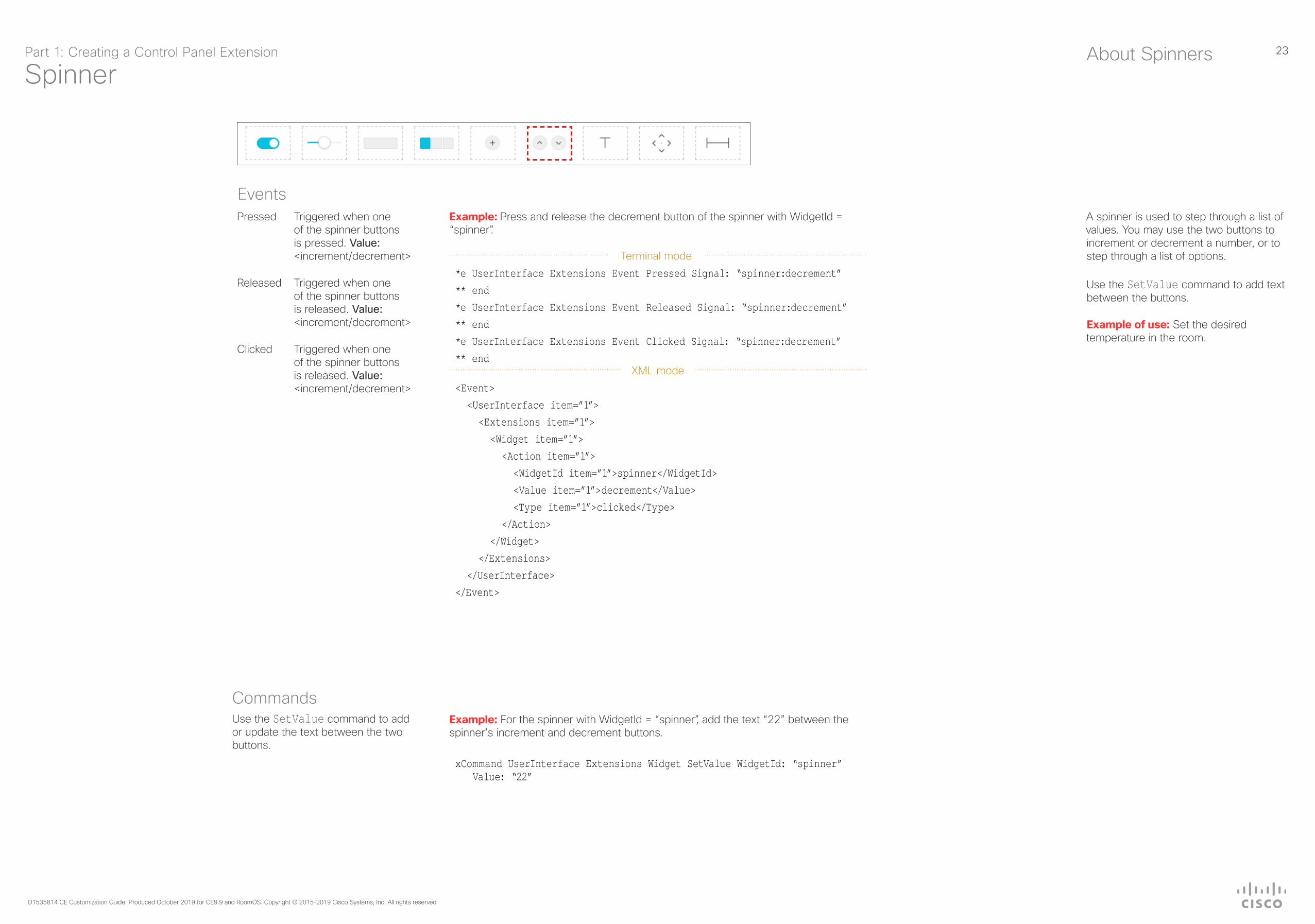
A spinner is used to step through a list of values. You may use the two buttons to increment or decrement a number, or to step through a list of options.
Use the SetValue command to add text between the buttons.
Example of use: Set the desired temperature in the room.
About Spinners
EventsExample: Press and release the decrement button of the spinner with WidgetId = “spinner”.
Terminal mode
*e UserInterface Extensions Event Pressed Signal: “spinner:decrement”** end*e UserInterface Extensions Event Released Signal: “spinner:decrement”** end*e UserInterface Extensions Event Clicked Signal: “spinner:decrement”** end
XML mode
<Event> <UserInterface item=”1”> <Extensions item=”1”> <Widget item=”1”> <Action item=”1”> <WidgetId item=”1”>spinner</WidgetId> <Value item=”1”>decrement</Value> <Type item=”1”>clicked</Type> </Action> </Widget> </Extensions> </UserInterface></Event>
Pressed Triggered when one of the spinner buttons is pressed. Value: <increment/decrement>
Released Triggered when one of the spinner buttons is released. Value: <increment/decrement>
Clicked Triggered when one of the spinner buttons is released. Value: <increment/decrement>
CommandsUse the SetValue command to add or update the text between the two buttons.
Example: For the spinner with WidgetId = “spinner”, add the text “22” between the spinner’s increment and decrement buttons.
xCommand UserInterface Extensions Widget SetValue WidgetId: “spinner” Value: “22”
Part 1: Creating a Control Panel Extension

24
D1535814 CE Customization Guide. Produced October 2019 for CE9.9 and RoomOS. Copyright © 2015–2019 Cisco Systems, Inc. All rights reserved
Text
Text boxes come in different sizes. They have up to two lines of text and the text automatically wraps to the new line.
A small text box with larger font size and no line wrap is also available.
You can define the initial text for the text box in the editor, and later on use the SetValue command to enter text dynamically.
Example of use: Help text, instructions, explanation of what different presets mean, or informative text from the control system, such as “The projector is warming up”.
The text box with larger font size is primarily meant for status values, such as the current temperature in the room.
About Texts
EventsNone
CommandsUse the SetValue command to set the text in the text box.
Example: Set the following text in the text box with WidgetId = “textbox”: “The projector is warming up.”.
xCommand UserInterface Extensions Widget SetValue WidgetId: “textbox” Value: “The projector is warming up.”
Part 1: Creating a Control Panel Extension

25
D1535814 CE Customization Guide. Produced October 2019 for CE9.9 and RoomOS. Copyright © 2015–2019 Cisco Systems, Inc. All rights reserved
Directional PadAbout Directional Pads
The Directional Pad can be regarded as a set of 5 buttons, the four Directional buttons and the Center button.
As can be seen from the examples at left, the event will be of the form:
“<WidgetId>:<the button pushed>”
in which the button pushed assumes the value:
up, down, left, right or center
Example of use: Controlling AppleTV
EventsExample: Press and release the button with WidgetId = “dirpad”.
Terminal mode
*e UserInterface Extensions Event Pressed Signal: “dirpad:up”** end*e UserInterface Extensions Event Released Signal: “dirpad:up”** end*e UserInterface Extensions Event Clicked Signal: “dirpad:up”** end
XML mode
<Event> <UserInterface item=”1”> <Extensions item=”1”> <Widget item=”1”> <Action item=”1”> <WidgetId item=”1”>dirpad</WidgetId> <Value item=”up”></Value> <Type item=”1”>clicked</Type> </Action> </Widget> </Extensions> </UserInterface></Event>
Pressed Triggered when the button is pressed. Value: N/A
Changed Triggered when the button is released. Value: N/A
Released Triggered when the button is released. Value: N/A
Part 1: Creating a Control Panel Extension

26
D1535814 CE Customization Guide. Produced October 2019 for CE9.9 and RoomOS. Copyright © 2015–2019 Cisco Systems, Inc. All rights reserved
Spacer
The Spacer lets you add space between or after widgets. It is no more than a layout tool.
The width of the spacer is adjustable (1–4). If you set it to maximum it will occupy its own line, making it usable as a vertical spacer, as well.
About Spacers
The Spacer is no more than a layout tool. Consequently, there are no events or commands associated with it.
Part 1: Creating a Control Panel Extension

27
D1535814 CE Customization Guide. Produced October 2019 for CE9.9 and RoomOS. Copyright © 2015–2019 Cisco Systems, Inc. All rights reserved
Removing Default Buttons

28
D1535814 CE Customization Guide. Produced October 2019 for CE9.9 and RoomOS. Copyright © 2015–2019 Cisco Systems, Inc. All rights reserved
Removing Default Buttons
What Is It?This feature adds the ability to hide default feature buttons in UI while still exposing custom Control buttons. This allows for a more customizable UI.
Even here you will need local admin access to the device to use the xConfigurations.
More specifically, what this feature does is to add a series of configurations that allow you to hide / display certain feature buttons in the UI that has previously not been possible to hide. The feature was new in CE9.6 and has been expanded to include Turn video On/Off button.
Functional OverviewThe following is at your disposal:
xconfig //userinterface/features ?*? xConfiguration UserInterface Features Call End: <Auto, Hidden>*? xConfiguration UserInterface Features Call MidCallControls: <Auto, Hidden>*? xConfiguration UserInterface Features Call Start: <Auto, Hidden>*? xConfiguration UserInterface Features Call VideoMute: <Auto, Hidden> *? xConfiguration UserInterface Features HideAll: <False, True>*? xConfiguration UserInterface Features Share Start: <Auto, Hidden>OK
The above configurations will also be available via the web interface of the Room Device. The default configurations are indicated in bold.
If you choose hide the Call (Start) button, this will also hide the default UI feature for making a call or do directory lookups / favorites / recent calls etc. In addition, the Add button which is used to add participants while in a call will be hidden.
The MidCallControls are Hold, Transfer and Resume.
Hiding the Share button will hide the default UI for sharing as well as hiding the ability to preview sources in- and out-of-call.
LimitationsThe feature applies to the Call, MidCallControls and Share sets of buttons only.
You cannot hide other single buttons whose display is a result of certain use cases, such as Meetings, Extension Mobility, Voicemail etc. These buttons must either be all displayed or all hidden.
If you choose to hide them all, only your custom-made buttons will be shown. To do this, use:
xConfiguration UserInterface Features HideAll: <False, True>
You may circumvent this all-or-nothing problem through selective provisioning of the settings from the back-end.
Note! This feature is about removing buttons only. The functions themselves are not removed. For instance, although the Share button may be be removed, the function will still be accessible via Proximity.
Example of UseExamples of how this can be implemented are shown on the following pages.
Sometimes you may want to create a completely customized UI for your users.
So far, this has not been possible as the Call button and Share button have always remained visible together with your Custom buttons.
This may cause confusion among users in scenarios where the Call or Share buttons have no meaning.
Why Remove Buttons?Part 1: Creating a Control Panel Extension

29
D1535814 CE Customization Guide. Produced October 2019 for CE9.9 and RoomOS. Copyright © 2015–2019 Cisco Systems, Inc. All rights reserved
ScenarioAssume that we want to create a scenario where users are limited to call a few specific rooms only. This could be the case in companies where external calls are never made. All calls are assumed to take place between this limited number of rooms.
Doing ItStarting out with a standard UI like this:
If we now issue the following command:
xConfiguration UserInterface Features HideAll: True
the UI will look like this:
Not very user-friendly, we shall therefore introduce a little In-Room Control magic.
Now, let’s open the In-Room Control editor and create this panel:
The name of the Panel is Make a Call, and that is what will appear below the button, once we’ve pushed the design to the codec:
If you now tap the Make a call button, the following panel will appear:
As a user there is not much that you will be able to do here, but that’s intentional. No mistakes or random calls possible. To call any of the three rooms possible just tap Make a Call followed by Dial next to the name of the room to be called.
To actually create and use this Control panel you will either need an external control device or create a Macro. Macros are described in the Macros section of this document.
This was an out-of-call example. Note that since we used the HideAll and introduced a panel that becomes effective outside calls only, the in-call behavor has been left undefined.
This must be dealt with, and on the next page we provide an in-call example rectifying this.
An Out-of-Call ExamplePart 1: Creating a Control Panel Extension

30
D1535814 CE Customization Guide. Produced October 2019 for CE9.9 and RoomOS. Copyright © 2015–2019 Cisco Systems, Inc. All rights reserved
An In-Call Example
ScenarioAs described on the previous page, we need to define in-call behavior as well. Otherwise, we will meet the following when in a call (no way to end the call):
Let’s create a setup:
This button is set to appear in calls only. Push this to the codec and the required functionality will be available:
In this example, once you tap the Call control button, the following will be displayed:
Note! The examples outlined in this chapter are just examples. There are lots of ways to create such scenarios.
Part 1: Creating a Control Panel Extension

31
D1535814 CE Customization Guide. Produced October 2019 for CE9.9 and RoomOS. Copyright © 2015–2019 Cisco Systems, Inc. All rights reserved
Command Reference

32
D1535814 CE Customization Guide. Produced October 2019 for CE9.9 and RoomOS. Copyright © 2015–2019 Cisco Systems, Inc. All rights reserved
Events
UserInterface Extensions Event PressedSent by the video system when a widget is first pressed.
Equivalent to the UserInterface Extensions Widget Action event with Type “Pressed”.
*e UserInterface Extensions Event Pressed Signal: Signalin which
Signal: String (0, 255)
The format of the string is “<WidgetId>:<Value>”, where <WidgetId> is the unique identifier of the widget that triggers the event, and <Value> is the value of the widget. The range of allowed values depends on the widget type.
UserInterface Extensions Event ChangedSent by the video system when changing a widget’s value (applies only to toggle buttons and sliders).
Equivalent to the UserInterface Extensions Widget Action event with Type “Changed”.
*e UserInterface Extensions Event Changed Signal: Signalin which
Signal: String (0, 255)
The format of the string is “<WidgetId>:<Value>”, where <WidgetId> is the unique identifier of the widget that triggers the event, and <Value> is the value of the widget. The range of allowed values depends on the widget type.
UserInterface Extensions Event ReleasedSent by the video system when a widget is released (even if moving the finger out of the widget before releasing it).
Equivalent to the UserInterface Extensions Widget Action event with Type “Released”.
*e UserInterface Extensions Event Released Signal: Signalin which
Signal: String (0, 255)
The format of the string is “<WidgetId>:<Value>”, where <WidgetId> is the unique identifier of the widget that triggers the event, and <Value> is the value of the widget. The range of allowed values depends on the widget type.
UserInterface Extensions Event ClickedSent by the video system when a widget is clicked (pressed and released without moving the finger out of the widget).
Equivalent to the UserInterface Extensions Widget Action event with Type “Clicked”.
*e UserInterface Extensions Event Clicked Signal: Signalin which
Signal: String (0, 255)
The format of the string is “<WidgetId>:<Value>”, where <WidgetId> is the unique identifier of the widget that triggers the event, and <Value> is the value of the widget. The range of allowed values depends on the widget type.
Part 1: Creating a Control Panel Extension

33
D1535814 CE Customization Guide. Produced October 2019 for CE9.9 and RoomOS. Copyright © 2015–2019 Cisco Systems, Inc. All rights reserved
Events (Cont.)
UserInterface Extensions Widget ActionSent by the video system when someone uses one of the controls on the user interface (in-room control panel).
Equivalent to the UserInterface Extensions Event Type event.
Depending on the action type, this event is equivalent to one of these events:
• UserInterface Extensions Event Pressed• UserInterface Extensions Event Changed • UserInterface Extensions Event Released • UserInterface Extensions Event Clicked Events
<Event>
<UserInterface item=”1”>
<Extensions item=”1”>
<Widget item=”1”>
<Action item=”1”>
<WidgetId item=”1”>WidgetId</WidgetId>
<Value item=”1”>Value</Value>
<Type item=”1”>Type</Type>
</Action>
</Widget>
</Extensions>
</UserInterface>
</Event>
in which:
WidgetId: String (0, 40) The unique identifier for the widget that triggered the event.
Value: String (0, 255) The value of the widget. The range of allowed values depends on the widget type.
Type: <Pressed/Changed/Released/Clicked>
Pressed: Sent when a widget is first pressed.
Changed: Sent when changing a widget’s value (only for toggle buttons and sliders).
Released: Sent when a widget is released (even if moving the finger out of the widget before releasing it).
Clicked: Sent when a widget is clicked (pressed and released without moving the finger out of the widget).
UserInterface Extensions Widget LayoutUpdatedSent by the video system when the configuration file for the user interface extensions has been updated, i.e. when exporting a new configuration from the in-room control editor to the video system.
*e UserInterface Extensions Widget LayoutUpdated
or
<Event>
<UserInterface item=”1”>
<Extensions item=”1”>
<Widget item=”1”>
<LayoutUpdated item=”1”/>
</Widget>
</Extensions>
</UserInterface>
</Event>
Part 1: Creating a Control Panel Extension

34
D1535814 CE Customization Guide. Produced October 2019 for CE9.9 and RoomOS. Copyright © 2015–2019 Cisco Systems, Inc. All rights reserved
Commands
UserInterface Extensions Widget SetValueThis command sets the value of the given widget, and the UserInterface Extensions statuses are updated accordingly. If the value is out of range, the command returns an error.
USAGE:
xCommand UserInterface Extensions Widget SetValue Value: Value WidgetId: WidgetId
in which
Value: String (0, 255)The value of the widget. The range of values depends on the widget type.
WidgetId: String (0, 40)The unique identifier for the widget.
UserInterface Extensions Widget UnsetValueThis command empties the value of the given widget, and the UserInterface Extensions statuses are updated accordingly. The user interface is notified that the widget is no longer selected.
USAGE:
xCommand UserInterface Extensions Widget UnsetValue WidgetId: WidgetId
in which
WidgetId: String (0, 40)The unique identifier for the widget.
UserInterface Extensions ClearThis command deletes all user interface extensions (widgets) from the video system.
USAGE:
xCommand UserInterface Extensions Clear
UserInterface Extensions ListUse this command to list all user interface extensions (widgets) that exist on the video system.
USAGE:
xCommand UserInterface Extensions List
Part 1: Creating a Control Panel Extension
35
D1535814 CE Customization Guide. Produced October 2019 for CE9.9 and RoomOS. Copyright © 2015–2019 Cisco Systems, Inc. All rights reserved
Statuses
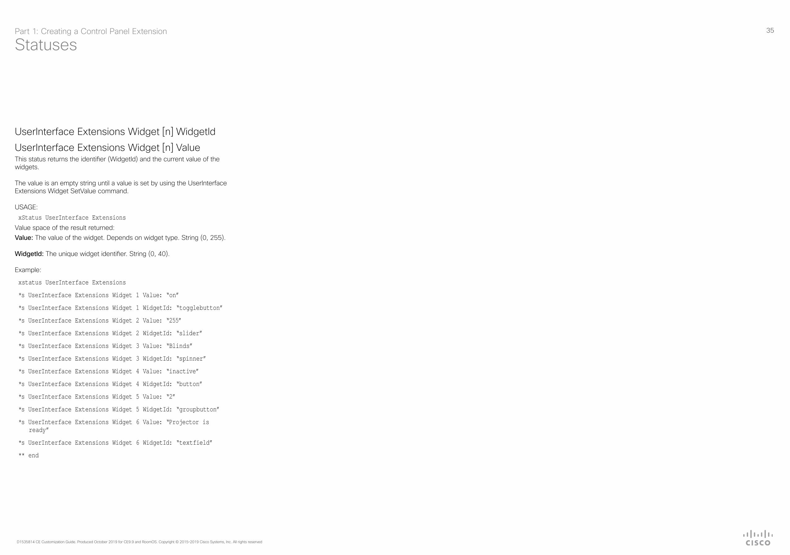
UserInterface Extensions Widget [n] WidgetId
UserInterface Extensions Widget [n] ValueThis status returns the identifier (WidgetId) and the current value of the widgets.
The value is an empty string until a value is set by using the UserInterface Extensions Widget SetValue command.
USAGE:xStatus UserInterface Extensions
Value space of the result returned:Value: The value of the widget. Depends on widget type. String (0, 255).
WidgetId: The unique widget identifier. String (0, 40).
Example:
xstatus UserInterface Extensions
*s UserInterface Extensions Widget 1 Value: “on”
*s UserInterface Extensions Widget 1 WidgetId: “togglebutton”
*s UserInterface Extensions Widget 2 Value: “255”
*s UserInterface Extensions Widget 2 WidgetId: “slider”
*s UserInterface Extensions Widget 3 Value: “Blinds”
*s UserInterface Extensions Widget 3 WidgetId: “spinner”
*s UserInterface Extensions Widget 4 Value: “inactive”
*s UserInterface Extensions Widget 4 WidgetId: “button”
*s UserInterface Extensions Widget 5 Value: “2”
*s UserInterface Extensions Widget 5 WidgetId: “groupbutton”
*s UserInterface Extensions Widget 6 Value: “Projector is ready”
*s UserInterface Extensions Widget 6 WidgetId: “textfield”
** end
Part 1: Creating a Control Panel Extension

36
D1535814 CE Customization Guide. Produced October 2019 for CE9.9 and RoomOS. Copyright © 2015–2019 Cisco Systems, Inc. All rights reserved
Creating Interactive Messages

37
D1535814 CE Customization Guide. Produced October 2019 for CE9.9 and RoomOS. Copyright © 2015–2019 Cisco Systems, Inc. All rights reserved
How Interactive Messages Work (I)
Example 1 — Rating Your Experience
xCommand UserInterface Message Prompt Display FeedbackId: “MeetingExperience” Text: “” Title: “How would you rate your meeting experience?” Option.1: “Fantastic” Option.2: “Good” Option.3: “Not Great”
*e UserInterface Message Prompt Response FeedbackId: “MeetingExperience”
*e UserInterface Message Prompt Response OptionId: 1
<XmlDoc resultId=””>
<Event>
<UserInterface item=”1”>
<Message item=”1”>
<Prompt item=”1”>
<Response item=”1”>
<FeedbackId item=”1”>MeetingExperience</FeedbackId>
<OptionId item=”1”>1</OptionId>
</Response>
</Prompt>
</Message>
</UserInterface>
</Event>
</XmlDoc>
Example 2 — Write Your Feedback Here
xCommand UserInterface Message TextInput Display FeedbackId: “MeetingFeedback” Placeholder: “Write your feedback here” SubmitText: “Next” Title: “Why, what didn’t you like?” Text: “Please let us know what we can improve. Your feedback is important to us.”
*e UserInterface Message TextInput Response FeedbackId: “MeetingFeedback”
*e UserInterface Message TextInput Response Text: “Low resolution”
<XmlDoc resultId=””>
<Event>
<UserInterface item=”1”>
<Message item=”1”>
<TextInput item=”1”>
<Response item=”1”>
<FeedbackId item=”1”>MeetingFeedback</FeedbackId>
<Text item=”1”>Low resolution</Text>
</Response>
</TextInput>
</Message>
</UserInterface>
</Event>
</XmlDoc>
The Messages feature lets you create alerting and /or interactive messages on the Touch10 / DX / Webex Board screen prompting the user to act accordingly.
If you want to create a sequence of messages where the next message depends on a choice made in the previous message, we recommend the use of macros to create events to act upon. Alternatively, you may use an external control device, which then will act upon the events created.
In order to submit inputs from the user, you should make use of HttpFeedback.
The HttpFeedback enables you to get the device to post http feedback messages (also known as webhooks) upon changes to the API state, e.g. statuses, events and configuration updates. The HTTP Post feedback messages will be sent to the specified ServerURL.
More about this can be found in the API Reference Guide.
Note that when you create messages as shown in example 2, at left, you may specify the text on the “Next” button. The “Cancel” button, however, appears by default and its text cannot be altered.
When you create messages using Message Alert as in example 4 (on the next page), the “Dismiss” button will appear by default. The text on this button cannot be altered.
About MessagesPart 1: Creating a Control Panel Extension

38
D1535814 CE Customization Guide. Produced October 2019 for CE9.9 and RoomOS. Copyright © 2015–2019 Cisco Systems, Inc. All rights reserved
How Interactive Messages Work (II)
Example 4 — Feedback Receipt
xCommand UserInterface Message Alert Display Title: “Feedback receipt” text: “Thank you for your feedback! Have a great day!”
*e UserInterface Message Alert Cleared
<XmlDoc resultId=””>
<Event>
<UserInterface item=”1”>
<Message item=”1”>
<Alert item=”1”>
<Cleared item=”1”/>
</Alert>
</Message>
</UserInterface>
</Event>
</XmlDoc>
Example 5 — Enter Your WebEx Pin
xCommand UserInterface Message TextInput Display FeedbackId: “WebExPin” InputType: Numeric Placeholder: “Please enter the host pin PIN” SubmitText: “Submit PIN” Text: “Please enter the host pin PIN, followed by #. Not the host: Press #” Title: “WebEx Pin”
*e UserInterface Message TextInput Response FeedbackId: “WebExPin”
*e UserInterface Message TextInput Response Text: “1122#”
<XmlDoc resultId=””>
<Event>
<UserInterface item=”1”>
<Message item=”1”>
<TextInput item=”1”>
<Response item=”1”>
<FeedbackId item=”1”>WebExPin</FeedbackId>
<Text item=”1”>1122#</Text>
</Response>
</TextInput>
</Message>
</UserInterface>
</Event>
</XmlDoc>
Example 3 — Getting In Touch With You
xCommand UserInterface Message TextInput Display FeedbackId: “ContactInfo” Placeholder: “Write your contact info here” SubmitText: “Next” Title: “Contact Info” Text: “Please let us know how we can contact you for a follow up”
*e UserInterface Message TextInput Response FeedbackId: “ContactInfo”
*e UserInterface Message TextInput Response Text: “[email protected]”
<XmlDoc resultId=””>
<Event>
<UserInterface item=”1”>
<Message item=”1”>
<TextInput item=”1”>
<Response item=”1”>
<FeedbackId item=”1”>ContactInfo</FeedbackId>
<Text item=”1”>[email protected]</Text>
</Response>
</TextInput>
</Message>
</UserInterface>
</Event>
</XmlDoc>
Part 1: Creating a Control Panel Extension

39
D1535814 CE Customization Guide. Produced October 2019 for CE9.9 and RoomOS. Copyright © 2015–2019 Cisco Systems, Inc. All rights reserved
HTTP(S) Requests
40
D1535814 CE Customization Guide. Produced October 2019 for CE9.9 and RoomOS. Copyright © 2015–2019 Cisco Systems, Inc. All rights reserved
Sending HTTP(S) Requests
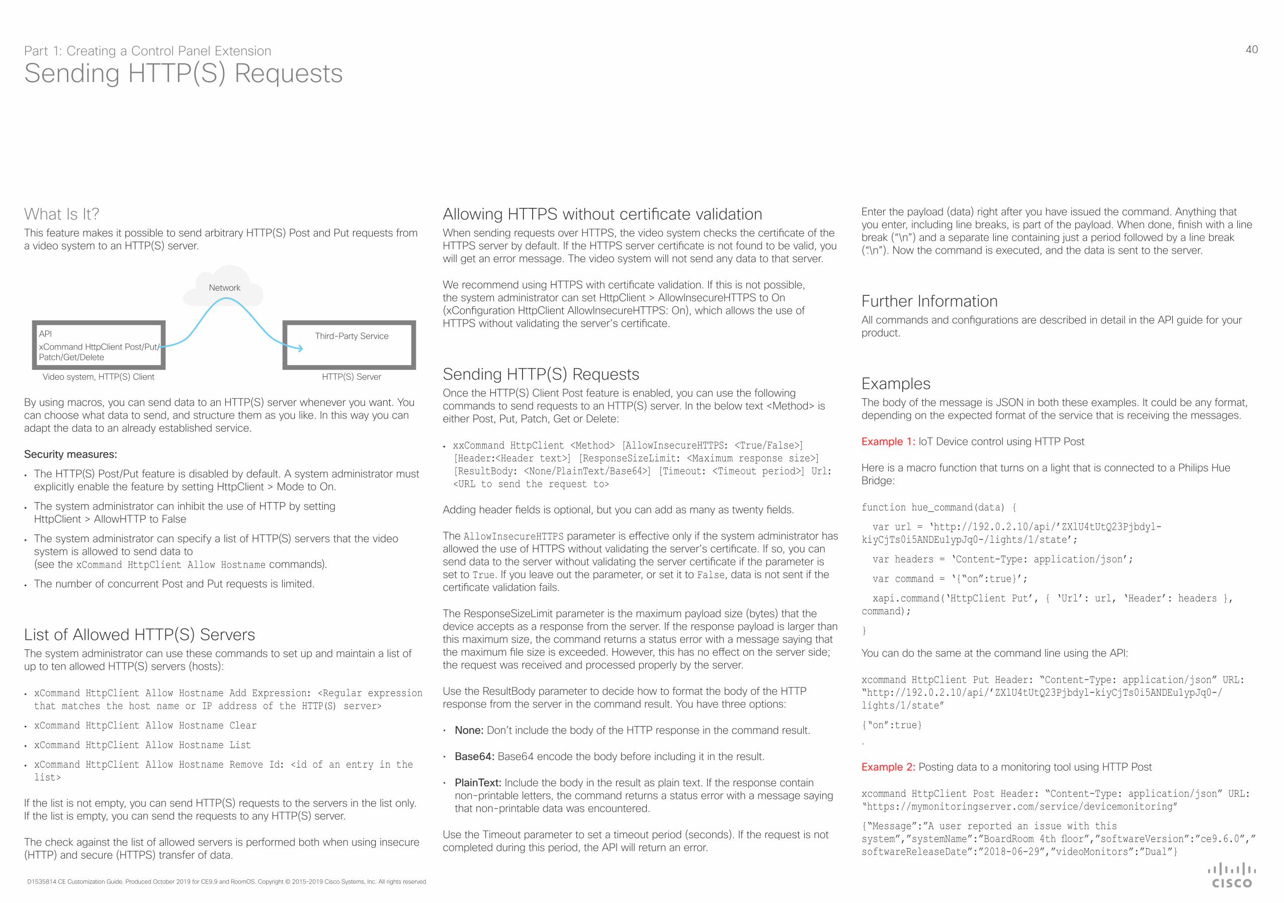
What Is It?This feature makes it possible to send arbitrary HTTP(S) Post and Put requests from a video system to an HTTP(S) server.
Network
Video system, HTTP(S) Client
APIxCommand HttpClient Post/Put/Patch/Get/Delete
HTTP(S) Server
Third-Party Service
By using macros, you can send data to an HTTP(S) server whenever you want. You can choose what data to send, and structure them as you like. In this way you can adapt the data to an already established service.
Security measures:
• The HTTP(S) Post/Put feature is disabled by default. A system administrator must explicitly enable the feature by setting HttpClient > Mode to On.
• The system administrator can inhibit the use of HTTP by setting HttpClient > AllowHTTP to False
• The system administrator can specify a list of HTTP(S) servers that the video system is allowed to send data to (see the xCommand HttpClient Allow Hostname commands).
• The number of concurrent Post and Put requests is limited.
List of Allowed HTTP(S) ServersThe system administrator can use these commands to set up and maintain a list of up to ten allowed HTTP(S) servers (hosts):
• xCommand HttpClient Allow Hostname Add Expression: <Regular expression that matches the host name or IP address of the HTTP(S) server>
• xCommand HttpClient Allow Hostname Clear
• xCommand HttpClient Allow Hostname List
• xCommand HttpClient Allow Hostname Remove Id: <id of an entry in the list>
If the list is not empty, you can send HTTP(S) requests to the servers in the list only. If the list is empty, you can send the requests to any HTTP(S) server.
The check against the list of allowed servers is performed both when using insecure (HTTP) and secure (HTTPS) transfer of data.
Allowing HTTPS without certificate validationWhen sending requests over HTTPS, the video system checks the certificate of the HTTPS server by default. If the HTTPS server certificate is not found to be valid, you will get an error message. The video system will not send any data to that server.
We recommend using HTTPS with certificate validation. If this is not possible, the system administrator can set HttpClient > AllowInsecureHTTPS to On (xConfiguration HttpClient AllowInsecureHTTPS: On), which allows the use of HTTPS without validating the server’s certificate.
Sending HTTP(S) RequestsOnce the HTTP(S) Client Post feature is enabled, you can use the following commands to send requests to an HTTP(S) server. In the below text <Method> is either Post, Put, Patch, Get or Delete:
• xxCommand HttpClient <Method> [AllowInsecureHTTPS: <True/False>] [Header:<Header text>] [ResponseSizeLimit: <Maximum response size>] [ResultBody: <None/PlainText/Base64>] [Timeout: <Timeout period>] Url: <URL to send the request to>
Adding header fields is optional, but you can add as many as twenty fields.
The AllowInsecureHTTPS parameter is effective only if the system administrator has allowed the use of HTTPS without validating the server’s certificate. If so, you can send data to the server without validating the server certificate if the parameter is set to True. If you leave out the parameter, or set it to False, data is not sent if the certificate validation fails.
The ResponseSizeLimit parameter is the maximum payload size (bytes) that the device accepts as a response from the server. If the response payload is larger than this maximum size, the command returns a status error with a message saying that the maximum file size is exceeded. However, this has no effect on the server side; the request was received and processed properly by the server.
Use the ResultBody parameter to decide how to format the body of the HTTP response from the server in the command result. You have three options:
• None: Don’t include the body of the HTTP response in the command result.
• Base64: Base64 encode the body before including it in the result.
• PlainText: Include the body in the result as plain text. If the response contain non-printable letters, the command returns a status error with a message saying that non-printable data was encountered.
Use the Timeout parameter to set a timeout period (seconds). If the request is not completed during this period, the API will return an error.
Enter the payload (data) right after you have issued the command. Anything that you enter, including line breaks, is part of the payload. When done, finish with a line break (“\n”) and a separate line containing just a period followed by a line break (“.\n”). Now the command is executed, and the data is sent to the server.
Further InformationAll commands and configurations are described in detail in the API guide for your product.
ExamplesThe body of the message is JSON in both these examples. It could be any format, depending on the expected format of the service that is receiving the messages.
Example 1: IoT Device control using HTTP Post
Here is a macro function that turns on a light that is connected to a Philips Hue Bridge:
function hue_command(data) {
var url = ‘http://192.0.2.10/api/’ZXlU4tUtQ23Pjbdyl-kiyCjTs0i5ANDEu1ypJq0-/lights/1/state’;
var headers = ‘Content-Type: application/json’;
var command = ‘{“on”:true}’;
xapi.command(‘HttpClient Put’, { ‘Url’: url, ‘Header’: headers }, command);
}
You can do the same at the command line using the API:
xcommand HttpClient Put Header: “Content-Type: application/json” URL: “http://192.0.2.10/api/’ZXlU4tUtQ23Pjbdyl-kiyCjTs0i5ANDEu1ypJq0-/lights/1/state”
{“on”:true}.
Example 2: Posting data to a monitoring tool using HTTP Post
xcommand HttpClient Post Header: “Content-Type: application/json” URL: “https://mymonitoringserver.com/service/devicemonitoring”
{“Message”:”A user reported an issue with this system”,”systemName”:”BoardRoom 4th floor”,”softwareVersion”:”ce9.6.0”,”softwareReleaseDate”:”2018-06-29”,”videoMonitors”:”Dual”}
Part 1: Creating a Control Panel Extension

41
D1535814 CE Customization Guide. Produced October 2019 for CE9.9 and RoomOS. Copyright © 2015–2019 Cisco Systems, Inc. All rights reserved
Troubleshooting

42
D1535814 CE Customization Guide. Produced October 2019 for CE9.9 and RoomOS. Copyright © 2015–2019 Cisco Systems, Inc. All rights reserved
Tips When Troubleshooting
Sign InSign in to the video system’s web interface with administrator credentials, navigate to Integration > UI Extensions EditorNEW. Click the arrow to show the Development Tools.
Overview of all Widgets and Their StatusThe Widget State Overview window lists all widgets, and their status. The status is shown in the Current Value column.
If the Current Value column is empty, the widget has not been initialized and has no value. We recommend that the control system initializes all widgets when it initially connects to the video system.
Send Value Updates to the Video SystemA control system sends SetValue commands to the video system, telling it to update a widget. For test purposes, you can use the Update Value column in the Widget State Overview window to simulate a control system.
Enter a value in one of the input fields to immediately send the corresponding SetValue command to the video system. The CurrentValue column (status) will be updated, and the Touch10 in-room control panel changes accordingly.
Click Unset to clear the value of the widget (send an UnsetValue command).
If a control system is connected to the video system, the Current Value and Update Value columns may come out-of-sync. The Current Value column always shows the current status, regardless of whether the SetValue command is sent from a real control system, or from the Update Value column.
Check for Events and Status UpdatesAll events and status updates related to widgets appear immediately in the Log window. Events are prefixed with *e, and statuses are prefixed with *s.
Events appear when you use the controls on the Touch 10 user interface, and the status is updated when a command, which changes the video system’s status, is sent to the video system.
If a Panel Fails to LoadIf an existing in-room control panel failed to load automatically on launching the editor, you may manually import the panel(s) from codec or load a local file made with the offline editor.
All alternatives erase any unsaved data in the editor, but the existing in-room control panel on the video system is neither overwritten nor deleted until a new panel is exported to the video system.
Make Sure That Macros Are Not the CauseIf you experience unintended behavioral changes and you run macros on your system, make sure you deactivate the macros before proceeding with your troubleshooting.
Use xConfiguration Macros Mode: On/Off to do this.
The macro framework has its own log file called macros.log
The macros.log file contains much of what is printed in the Macro console. The macros can be configured to print output to the console and this will be stored in the log, so keep in mind that you can see custom log messages (which must have been created by the developer) in this file.
Part 1: Creating a Control Panel Extension

43
D1535814 CE Customization Guide. Produced October 2019 for CE9.9 and RoomOS. Copyright © 2015–2019 Cisco Systems, Inc. All rights reserved
Tips and Tricks

44
D1535814 CE Customization Guide. Produced October 2019 for CE9.9 and RoomOS. Copyright © 2015–2019 Cisco Systems, Inc. All rights reserved
Recommended Best Practice
Re-register to Get Feedback After RestartWhen either the video system or the control system restarts, the control system must re-register to the events that the video system sends when someone uses the custom controls or pushes a new Control panel to the system.
For terminal output mode:
xfeedback register event/UserInterface/Extensions/Widget
For XML output mode:
xfeedback register event/UserInterface/Extensions/Event
xfeedback register event/UserInterface/Extensions/Widget/LayoutUpdated
Consult the API for in-room control chapter for more details.
Initialize All WidgetsMake sure the control system initializes all the widgets on the Control panel in the following situations:
• When the control system connects to the video system for the first time
• When the video system restarts
• When the control system restarts
• When a new Control panel is exported to the video system (as response to a LayoutUpdated event).
If this is not done, then the system screen may show incorrect values and not truly reflect the status of the room.
Use the SetValue command to set the initial values.
Always send values back to the video system when something changes.
To avoid unexpected behavior and ambiguities, the control system must always send SetValue commands to the video system when something changes. This applies also when the change is triggered by someone using the controls on the system.
For example, it makes no difference if you use a slider on the Control panel to dim the light, or a physical dimmer in the room, or another touch panel. The control system must always send the dimmer value back to the video system using the SetValue command.
Update the Control PanelWhen you export a new Control panel to the video system, the old panel is overwritten and replaced by the new one.
To update, do as follows:
1. Launch the UI Extensions Editor from the video system’s web interface.2. Create the Control panel you want, or import a previously saved panel from file
(Import > From file).3. Click Export > To codec.
Other Useful StuffRemember previous values when turning lights off (e.g. a light with a slider for dimming and toggle for on/off), remember the current light state when turning off, and use that value when turning back on.
Example: If the light is at 40%, and the user presses off, she will expect it to go back to 40% (not 100%) when pressing the “on” again. Remember also to set the power switch to off if sliding to 0%.
For blinds, consider using the following strategy: Short press on a Direction arrow tilts the blinds. If tilted all the way already, a short press moves the blinds slightly.
Long press on a Direction arrow starts moving the blind that direction, doesn’t stop until blinds are all the way up /down.
To stop movement after long pressing, short press any button (stop button is not really necessary)
Remove an Entire Control Panel and It’s IconIf there is a Control panel on the video system then there is also a corresponding Control icon, either in the Touch 10 / DX / Webex Board status bar or as a button to the right of the call control buttons. Even if a panel is empty and contains no widgets, both the icon and the panel will be visible.
Do as follows to remove a Control panel and icon from system: 1. Launch the UI Extensions Editor from the video system’s web interface.2. Select the panel to be removed (Global, Homescreen or In-call) 3. Click Delete panel.
Transition From Third-party Control Systems to CEIf you already have been using a third party control system and want to start using CE as described in this document, we recommend the following:
• Let any programming made to control third party stuff remain untouched.
• Remove all code that controls the Cisco video endpoint as that is now already controlled via the Ui Extension.
• Reprogram the signaling from the button-presses coming from the third party control system panel so that it listens to button presses from the Touch10 / DX / Webex Board instead.
This programming can be very simple to do as the largest control system manufacturers provide modules/drivers for Controls making it very easy to get started with the programming.
Part 1: Creating a Control Panel Extension

45
D1535814 CE Customization Guide. Produced October 2019 for CE9.9 and RoomOS. Copyright © 2015–2019 Cisco Systems, Inc. All rights reserved
Recommended Best Practice (cont.)
Inspirational ExamplesThe following examples may serve as inspiration and to provide further guidance on best practices. It is by no means mandatory to design and implement controls as illustrated in these examples.
Widget IDWhen you drag a widget (e.g. a button) onto a page, you may give it a customized ID. Widget IDs do not have to be unique. Widgets can share ID, but they must be of the same type. This means that you can have two sliders in different panels called “main-light”, but you cannot have one slider and one toggle button both called “main-light”.
To create a duplicate of an existing widget on another page or panel, just use Copy and Paste.
Create Groups of What Belongs TogetherConsider grouping controls that belong together on the same page. The pages you create in the in-room control editor appear as separate tabs on the control panel.
Control of LightsThe combination of a slider and a toggle button could be used to control lights. The toggle button switches the lights on or off; the slider serves as a dimmer.
Consider the following strategy:
• Set a slider to minimum when the user turns the lights off.• Set a toggle button to off when the user moves the slider to its minimum.• Remember the value of the slider when the lights are turned off, so that you
can return to this value when the lights are turned back on again.• If the light is at 40 %, when the user switches it off, he or she would expect it
to go back to 40 % (not maximum) when switching the lights on again.• When the user selects one of the options in the group button (a light preset),
set the sliders and toggle buttons accordingly.• If the lights are changed away from a preset, for instance by changing a slider
or toggle button, deselect all options in the group button.
Control of TemperatureThe combination of a spinner and a large font text box (value) may be used to control temperature. Use the spinner to set the desired temperature, and the large font text box to show the current temperature.
For the best user experience keep the following in mind:
• Update the large font text box as the temperature in the room changes. Update the text field of the spinner when someone tap the up and down arrows
• Consult the Widgets chapter for details about how to update the spinner’s text field and the large font text box.
Control of BlindsYou can either use a spinner, or up and down arrows from the Icons tab in the widget library.
Consider the following strategy:
• Tilt the slides as response to a short press on a direction arrow. If tilted all the way, move the blinds up or down incrementally.
• As response to a long press on a direction arrow, start moving the blinds in that direction. They do not stop until all the way up or down.
• Short press any button in order to stop the movement after a long press. Then no separate stop button will be needed.
Group Buttons Group buttons (radio buttons) are ideal when you want buttons to be linked, so that only one can be selected at a time. For example room presets. When the individual buttons in a group are too small to contain the text that describes their function, consider to use text boxes for the description.
Create Speed Dial or One Button to PushIf you want to create buttons on the screen that directly result in an action without displaying any kind of panels or settings, do as follows:
• Create a new panel and follow the on-screen instructions.
When you tap on the button on the screen, this will directly create an event, which in turn can be used to start an action. Typical examples of use of this feature is Speed Dialing or One Button to Push solutions.
Make sure you give the button a descriptive name for the user, if applicable.
Part 1: Creating a Control Panel Extension

46
D1535814 CE Customization Guide. Produced October 2019 for CE9.9 and RoomOS. Copyright © 2015–2019 Cisco Systems, Inc. All rights reserved
Granting Access to the UI Extensions Editor and the Extensions API
In order to access the UI Extensions Editor you will need to have administrator rights.However, an administrator may create an UI Extensions Editor User account. With this account it is possible to log into the codec to run the Editor. No other part of the web interface is accessible from this account.If you use SSH to log into the codec, only a very limited set of the API will be accessible.
Part 1: Creating a Control Panel Extension

47
D1535814 CE Customization Guide. Produced October 2019 for CE9.9 and RoomOS. Copyright © 2015–2019 Cisco Systems, Inc. All rights reserved
Creating WebApps

48
D1535814 CE Customization Guide. Produced October 2019 for CE9.9 and RoomOS. Copyright © 2015–2019 Cisco Systems, Inc. All rights reserved
WebApp ExtensionsPart 1: Creating a Webapp Extension
The WebApp Extension lets you create a button which will launch a web view in full screen on the main monitor. To add a WebApp button requires Web Engine to have been enabled.
Note! WebApps can be used on Webex Board only. WebApps are available outside calls only.
Creating a WebApp button is very similar to creating buttons with panels, as described on page 8 and onwards.
The only fields applicable to this application, are the URL of the website and a URL to get the Favicon if that fails to be obtainable from the website.
Note that the Favicon will not be displayed in the Editor, nor in the Preview. It will be visible on the endpoint as the lower image at left indicates (using Twitter as example).
About WebApp
To enter the WebApp Extension Editor, see “Launching the Editor” on page 8.

49
D1535814 CE Customization Guide. Produced October 2019 for CE9.9 and RoomOS. Copyright © 2015–2019 Cisco Systems, Inc. All rights reserved
Part 2Use of a Video Switch

50
D1535814 CE Customization Guide. Produced October 2019 for CE9.9 and RoomOS. Copyright © 2015–2019 Cisco Systems, Inc. All rights reserved
Using a Third-party Video Switch to Extend the Number of Video Sources AvailablePart 2: Use of a Video Switch
The UI EXtensions Editor can configure your system to show video sources from a third-party external video switch in the normal Share Tray view.
The sources will appear — and behave — as any other video source connected directly to the codec. For the user this will be perceived as completely transparent — no video switch will seem to be involved.
The video switch feature requires a third-party control system. The control system will use the Codec API to synchronize the source states between the video switch and your system’s user interface using a set of API events and commands.
In order to make this work when the user selects a video source, the codec must be set to issue a corresponding event, which in turn shall cause the controller to send appropriate commands to the video switch and the codec.
This event will be issued only if the controller has registered to the codec upon connection, requesting the following from the codec:
xFeedback register Event/UserInterface/Presentation/ExternalSource
The event issued will be as follows:
*e UserInterface Presentation ExternalSource Selected SourceIdentifier: “XXXX”
Where “XXXX” is a unique string ID used to identify this source when selecting or setting state — see the following pages for more on this.
Furthermore, there are six commands available to control the system:
Add: Adds video source identifiers, including ID of connector, the name to appear on the screen, a unique string ID to identify a source when selecting or setting state, and what type of icon to display on the screen for each source.
List: Returns the current list of external sources.
Remove: Removes a source from the list.
RemoveAll: Removes all of the sources from the list.
Select: Selects a specific source.
State Set: Changes the state of a source.
These are all presented in detail on the following pages.
A simple example of a setup using the configuration shown above is provided in the article “Video Switch Example” on page 52.
HDMI Out HDMI Input
1 2 3 4 5 6
Video input sources(PC, Cameras, DVD, Document Camera, Apple TV, Chromecast etc)
Third-party Video Switch (simplified for clarity)
Cisco Codec
Third-party Controller
LAN connection, Serial connection
etc.
LAN connection, Serial connection
etc.

51
D1535814 CE Customization Guide. Produced October 2019 for CE9.9 and RoomOS. Copyright © 2015–2019 Cisco Systems, Inc. All rights reserved
Command DetailsPart 2: Use of a Video Switch
UserInterface Presentation ExternalSource AddThis command establishes and defines an input source.
xcommand UserInterface Presentation ExternalSource Add ConnectorId: ConnectorId Name: Name SourceIdentifier: SourceIdentifier Type: Type
in which:
ConnectorId: The ID of the codec connector to which the external switch is connected
Name: Name displayed on the screen
SourceIdentifier: A unique string ID used to identify this source when selecting or setting state
Type: Decides what icon is displayed on the screen, choose between: <pc/camera/desktop/document_camera/mediaplayer/other/whiteboard>
Example:
xcommand UserInterface Presentation ExternalSource Add ConnectorId: 3 Name: “Blu-ray” SourceIdentifier: bluray Type: mediaplayer
UserInterface Presentation ExternalSource ListThis command returns the current list of external sources.
xcommand UserInterface Presentation ExternalSource List
UserInterface Presentation ExternalSource RemoveThis command removes a source from the list.
xcommand UserInterface Presentation ExternalSource Remove SourceIdentifier: SourceIdentifier
in which:
SourceIdentifier is a unique string ID used to identify this source when selecting or setting state.
UserInterface Presentation ExternalSource RemoveAllThis command removes all sources from the list.
xcommand UserInterface Presentation ExternalSource RemoveAl
UserInterface Presentation ExternalSource SelectStarts to present the selected source if it is in ready state and has a valid ConnectorId. Also shows the item in sharetray as “Presenting”.
xcommand UserInterface Presentation ExternalSource Select SourceIdentifier: SourceIdentifier
in which:
SourceIdentifier is a unique string ID used to identify this source when selecting or setting state.
UserInterface Presentation ExternalSource State SetUsed to change state of the source with SourceIdentifier.
xcommand UserInterface Presentation ExternalSource State Set SourceIdentifier: SourceIdentifier State: State [ErrorReason: ErrorReason]
in which:
SourceIdentifier: is a unique string ID used to identify this source when selecting or setting state
State: <Error/Hidden/NotReady/Ready> Ready is the only presentable state, hidden exists in the list but does not show in the sharetray.
ErrorReason: Optional. Displays in the share tray if the state is set to Error.

52
D1535814 CE Customization Guide. Produced October 2019 for CE9.9 and RoomOS. Copyright © 2015–2019 Cisco Systems, Inc. All rights reserved
Video Switch ExamplePart 2: Use of a Video Switch
A simple example of setup could be:
Controller sending:
xcommand UserInterface Presentation ExternalSource Add ConnectorId: 3 Name: “Blu-ray” SourceIdentifier: bluray Type: mediaplayer
xcommand UserInterface Presentation ExternalSource Add ConnectorId: 3 Name: “Apple TV” SourceIdentifier: appletv Type: mediaplayer
xcommand UserInterface Presentation ExternalSource Add ConnectorId: 3 Name: “TV” SourceIdentifier: tv Type: mediaplayer
The default state is NotReady (Fig. 1)So the next step for an integrator would be to set them to ready (Fig. 2).
xcommand UserInterface Presentation ExternalSource State Set State: Ready SourceIdentifier: bluray
xcommand UserInterface Presentation ExternalSource State Set State: Ready SourceIdentifier: appletv
xcommand UserInterface Presentation ExternalSource State Set State: Ready SourceIdentifier: tv
If one of the sources is selected on the video switch the controller should send a command accordingly:
xcommand UserInterface Presentation ExternalSource Select SourceIdentifier: tv
If the switch is connected on the chosen connector it will start to present (Fig. 3).When a user selects another source, by clicking the other source item in the share tray, the codec will send the following event:
*e UserInterface Presentation ExternalSource Selected SourceIdentifier: “appletv”
The Controller should listen to this event and display the selected source.
Note! The presentation will not start if the below setting has been set to Manual:xconfiguration Video Input Connector [x]
PresentationSelection: <AutoShare, Desktop, Manual, OnConnect>
Fig. 3 If the switch is connected on the chosen connector it will start to present.
Fig. 1 Default state is NotReady.
Fig. 2 When Input sources have been set to Ready.

53
D1535814 CE Customization Guide. Produced October 2019 for CE9.9 and RoomOS. Copyright © 2015–2019 Cisco Systems, Inc. All rights reserved
Part 3Working with Macros

54
D1535814 CE Customization Guide. Produced October 2019 for CE9.9 and RoomOS. Copyright © 2015–2019 Cisco Systems, Inc. All rights reserved
Creating MacrosPart 3: Working with Macros
Macros allow you to write snippets of JavaScript code that can automate parts of your video endpoint, thus creating custom behavior.
Note! The SX10 does not support macros.
Sign in to the video system’s web interface with administrator credentials and navigate to Integration > Macro Editor.
The first time this is done on a codec, you will be asked whether to enable the use of macros on this codec.
You may later disable the use of macros from within the Macro Editor. This will not permanently disable macros from running. Every time the codec is restarted, the macros will be re-enabled automatically.
To disable automatic restart, you must use the xConfiguration Macros Mode: Off.
You may want to use this command in the event of unintended behavior by the system. In such cases you should always disable the macros before proceeding with your troubleshooting.
The Macro Framework has many benefits, as it allows integrators to:
• Tailor their deployments.
• Create their own “features” or “workarounds” to functionality Cisco is reluctant to provide in form of a new software feature.
• Automate scenarios / re-configurations.
• Create custom tests or monitoring.
With the Macros, UI Extensions controls no longer need an external control system to activate local functionality.
However, performing local actions via the xAPI, such as to control other things like lights and blinds will still require a suitable third-party control system.
Examples of local functionality can be a Control panel for speed dialing or to trigger a “Room Reset” that puts all the configurations back to default (input sources, camera presets etc.).
Note! The Macro Framework is limited to local xAPI interaction. You cannot establish remote network connections to servers to push or receive data via the Macro Framework code.
Disclaimer: Cisco will support the Macro Framework itself only. Cisco will not support code that fails to compile or fails to work as the developer “intended”. It is entirely up to the person writing the code to ensure that the syntax is correct and that possessed coding skills are sufficient to write macros in JavaScript.
Please refer to public developer forums, the API Reference Guide of the product in question, as well as the Help section of the Macro editor. See also the following pages for more.
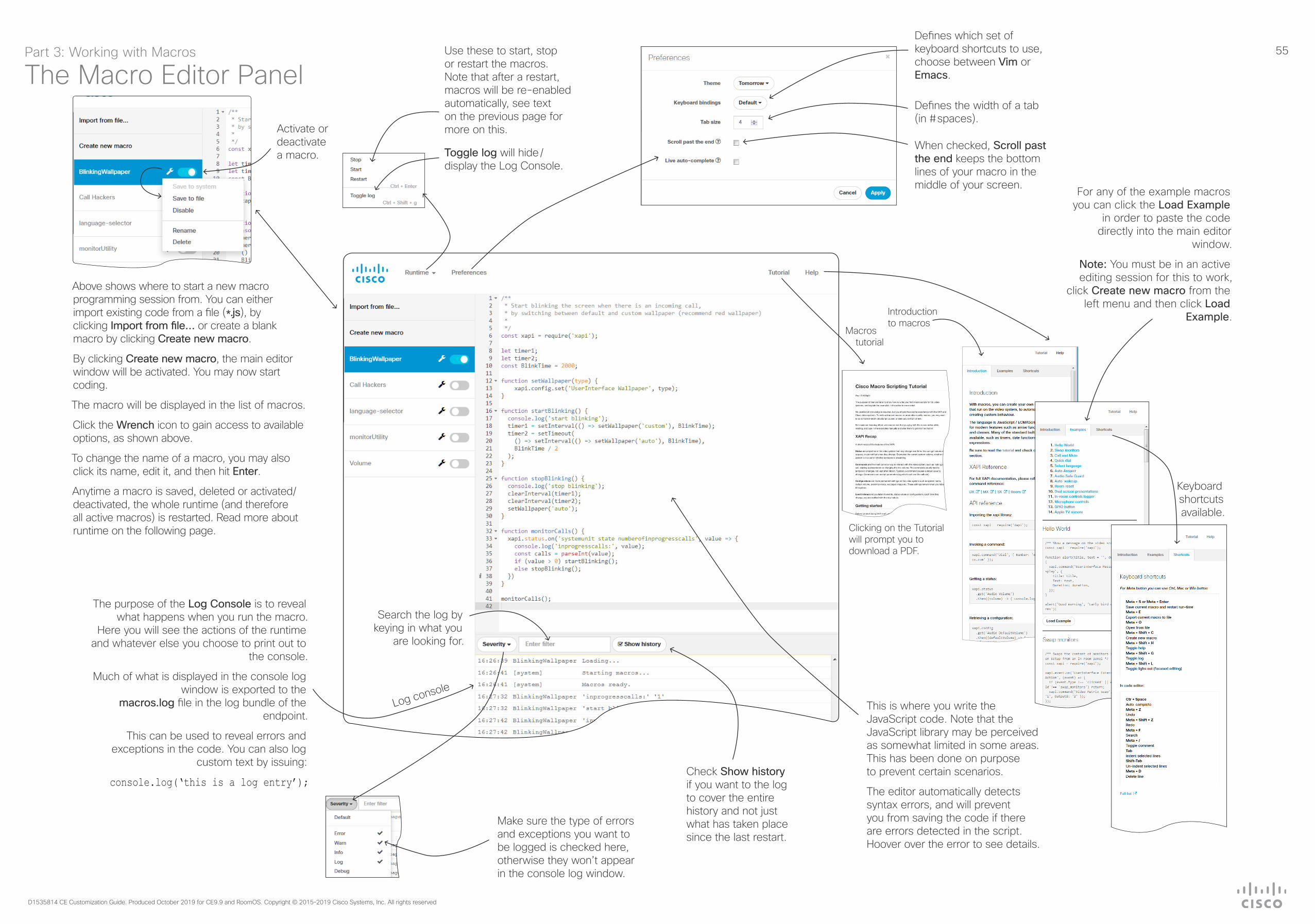
55
D1535814 CE Customization Guide. Produced October 2019 for CE9.9 and RoomOS. Copyright © 2015–2019 Cisco Systems, Inc. All rights reserved
For any of the example macros you can click the Load Example
in order to paste the code directly into the main editor
window.
Note: You must be in an active editing session for this to work,
click Create new macro from the left menu and then click Load
Example.
Search the log by keying in what you
are looking for.
Make sure the type of errors and exceptions you want to be logged is checked here, otherwise they won’t appear in the console log window.
The purpose of the Log Console is to reveal what happens when you run the macro.
Here you will see the actions of the runtime and whatever else you choose to print out to
the console.
Much of what is displayed in the console log window is exported to the
macros.log file in the log bundle of the endpoint.
This can be used to reveal errors and exceptions in the code. You can also log
custom text by issuing:
console.log(‘this is a log entry’);
Activate or deactivate a macro.
Defines which set of keyboard shortcuts to use, choose between Vim or Emacs.
Use these to start, stop or restart the macros. Note that after a restart, macros will be re-enabled automatically, see text on the previous page for more on this.
Defines the width of a tab (in # spaces).
When checked, Scroll past the end keeps the bottom lines of your macro in the middle of your screen.
Toggle log will hide /display the Log Console.
Above shows where to start a new macro programming session from. You can either import existing code from a file (*.js), by clicking Import from file… or create a blank macro by clicking Create new macro.
By clicking Create new macro, the main editor window will be activated. You may now start coding.
The macro will be displayed in the list of macros.
Click the Wrench icon to gain access to available options, as shown above.
To change the name of a macro, you may also click its name, edit it, and then hit Enter.
Anytime a macro is saved, deleted or activated/deactivated, the whole runtime (and therefore all active macros) is restarted. Read more about runtime on the following page.
This is where you write the JavaScript code. Note that the JavaScript library may be perceived as somewhat limited in some areas. This has been done on purpose to prevent certain scenarios.
The editor automatically detects syntax errors, and will prevent you from saving the code if there are errors detected in the script. Hoover over the error to see details.
Part 3: Working with Macros
The Macro Editor Panel
Keyboard shortcuts available.
Introduction to macros
Macros tutorial
Check Show history if you want to the log to cover the entire history and not just what has taken place since the last restart.
Clicking on the Tutorial will prompt you to download a PDF.
Log console

56
D1535814 CE Customization Guide. Produced October 2019 for CE9.9 and RoomOS. Copyright © 2015–2019 Cisco Systems, Inc. All rights reserved
Macros can alter the expected behavior of the system. If your macro is likely to surprise or confuse normal users, let them know with e.g. a notification on the video system screen.
We recommend that you never let macros depend on other macros. You can, of course, create several macros that listen to the same xapi values, e.g. the call state, as long as their actions are independent of each other.
Note that extensive use of macros may slow down codec performance due to heavy load.
Currently, macros cannot get or send data externally, e.g. to control lights in the room. For this you will need an external control system. However, it can be useful to combine macros and external systems, for example using a Crestron for light control at a low level, and then use macros to adjust in a more sophisticated way, such as adjusting the light depending on presentation status, call status etc.
Your macros may contain customized text to be displayed on the Touch10 / DX. This text may alert users to observe the activation or deactivation of certain features as well as alert them to act in accordance with the message given, etc.
Such text can be purely informative, but it may also prompt the user to respond to it by keying in information. This information may, in turn, cause the video system to directly act upon it. See also “Sending HTTP(S) Requests” on page 40.
About Macro RuntimeAll the activated macros run in a single process on the video endpoint, called the macro runtime. It should be running by default, but you can choose to stop and start it manually from the editor. If you restart the video endpoint, the runtime will automatically start again if xconfiguration macros autostart is On.
If any macro becomes unresponsive (fails to respond within a few seconds due to e.g. an infinite loop), a safety mechanism will stop the runtime, thereby stopping all macros.
The runtime will then be automatically restarted after a few seconds. This will continue, but the time between restarts will increase every time the runtime is shut down. If this happens more than a certain number of times, this will cause a system diagnostic to be displayed to notify that the macros are having problems.
Learning Resources AvailableIf you want to learn about how to utilize the macros feature, may we recommend the following:
• Read through the Introduction to Macros, which can be found in the Help section of the Macro Editor.
• Read through the Macros Tutorial, which is also found in the Macro Editor. This tutorial is also available as a free download from cisco.com.
• The Macro Editor even contains several examples ready for use. All these examples may be loaded in to the editor and studied there, or they may be used as is in your configurations. They may, of course, also serve as basis for further refinement, if you so wish.
Disable Macros When TroubleshootingIf you experience unintended behavioral changes and you run macros on your system, make sure you deactivate the macros before proceeding with your troubleshooting.
Use xConfiguration Macros Mode: On/Off to do this.
The macro framework has its own log file called macros.log
The macros.log file contains much of what is printed in the Macro console. The macros can be configured to print output to the console and this will be stored in the log, so keep in mind that you can see custom log messages (which must have been created by the developer) in this file.
Part 3: Working with Macros
Things to ObserveAn Introduction
to Macros can be found in the Help section of Macro
Editor.
For any of the example macros you can click the Load Example in order to paste the code directly into the main editor window. See the previous page for more.
The Tutorial provides most
of what you will need to know
to start creating your own macros.
Note that clicking on the Tutorial
will prompt you to download a PDF.

57
D1535814 CE Customization Guide. Produced October 2019 for CE9.9 and RoomOS. Copyright © 2015–2019 Cisco Systems, Inc. All rights reserved
Part 4Incorporating Third-party
USB Control Devices

58
D1535814 CE Customization Guide. Produced October 2019 for CE9.9 and RoomOS. Copyright © 2015–2019 Cisco Systems, Inc. All rights reserved
About the USB Control Device FunctionalityPart 4: Incorporating Third-party USB Control Devices
What Is It?This feature lets you use a third-party USB input device to control certain functions on, or behavior of, a video system. Examples of such devices could be a Bluetooth remote control (with a USB dongle) or a USB keyboard.
Note! To make this work you must define and implement any action the use of such input devices is meant to cause — there is no such as a library of actions readily available to pick actions from.
This feature is not meant to replace the Touch 10 or the DX user interface, but it may complement parts of their functionalities, wherever convenient.
Input Device RequirementsThe input device must advertise itself as a USB keyboard. The term keyboard should not necessarily be understood literally here — a Bluetooth remote control with a USB dongle will do the trick.
Functional OverviewPressing a button on the USB input device will generate an event in the API. Macros or third-party control devices can listen for such events and respond to them. This is similar to the In-Room Control buttons on the Touch 10 user interface. It is also possible to listen for the events via webhooks, directly in an SSH session.You must implement the actions to be taken as response to these events. For example:• Increase the volume of the video system when the Volume Up key is pressed.• Put the video system in Standby Mode when the Sleep key is pressed.
Note! The support for third-party USB input devices is disabled by default. This means that you must explicitly enable it. Set the Peripherals > InputDevice > Mode to On
Pressing and releasing a button will generate a Pressed and a Released event, like this:
*e UserInterface InputDevice Key Action Key: <Name of key>*e UserInterface InputDevice Key Action Code: <Id of key>*e UserInterface InputDevice Key Action Type: Pressed** end*e UserInterface InputDevice Key Action Key: <Name of key>*e UserInterface InputDevice Key Action Code: <Id of key>
*e UserInterface InputDevice Key Action Type: Released** end
To listen for events, you must register feedback from the InputDevice events:
xFeedback Register /event/UserInterface/Inputdevice** end
When the input device is detected by the video system, it shows up in the UserInterface > Peripherals > ConnectedDevice status. Note that the input device may be reported as multiple devices.
For a practical example, see the following page.
Examples of applications for this feature will typically be:
In classrooms and during lectures, a small remote control can be used to to wake up systems from standby mode and select which input source to present.
Control of pan, tilt and zoom of a camera in situations where Touch 10 is an inconvenient alternative or not allowed to be used (for instance in operating rooms in hospitals combined with telemedicine).
Why This Feature?

59
D1535814 CE Customization Guide. Produced October 2019 for CE9.9 and RoomOS. Copyright © 2015–2019 Cisco Systems, Inc. All rights reserved
This example shows how to use the keys of a third-party USB input device (in this case a remote control) to control the standby function, increase and decrease the volume, as well as to control the camera of a room or desk device.
The macro created will listen for relevant events, and carry out the associated actions using the API of the room or desk device.
Note! In the command examples below the text in normal font is entered by you, and the text in italics is the response received from the room device.
1 Sign in to the room or desk device on SSH. You need a local admin user.
2 Configure the device to allow the use of a 3rd party USB remote control.
xConfiguration Peripherals InputDevice Mode: On** end
OK
Note! You can check if the configuration is On or Off by using this command:
xConfiguration Peripherals InputDevice Mode*c xConfiguration Peripherals InputDevice Mode: On** end
OK
3 Register for feedback, so that we are notified when the remote control buttons are pressed and released.xFeedback Register /event/userinterface/inputdevice** end
OK
Note:! You can check which feedbacks the device is registered for, using this command:
xFeedback list/event/userinterface/inputdevice** end
OK
4 Press and release a button on the remote control to check that feedback registration works.
This generates two different events: Pressed and Released. If you press and hold a button you see the Pressed event until you release the button. Then the Released event is generated.
These are the events issued when pressing and releasing the Enter key:
*e UserInterface InputDevice Key Action Key: KEY_ENTER*e UserInterface InputDevice Key Action Code: 28*e UserInterface InputDevice Key Action Type: Pressed** end
*e UserInterface InputDevice Key Action Key: KEY_ENTER*e UserInterface InputDevice Key Action Code: 28*e UserInterface InputDevice Key Action Type: Released** end
5 Write a macro that listens for the relevant InputDevice events, and carries out the associated actions using the API of the device.
a Bring the standby, volume up and volume down buttons to life.
When the macro sees an event containing KEY_VOLUMEUP, KEY_VOLUMEDOWN, or KEY_SLEEP it executes the related commands.
b Create a camera control function for the arrow keys. We want to keep moving the camera as long as the button is pressed. When the button is released, the camera movement should stop.
When the macro sees an event containing KEY_LEFT, KEY_RIGHT, KEY_UP, or KEY_DOWN, it executes the related commands.
The parts related to the camera control function is highlighted with bold font in the code below.
const xapi = require(‘xapi’);
function com(command, args=’’) { xapi.command(command, args); log(command + ‘ ‘ + JSON.stringify(args));}
function log(event) { console.log(event);}
function notify(message) { xapi.command(‘UserInterface Message TextLine Display’, { Text: message, duration: 3 });}
function cameraControl(motor, direction, cameraId=’1’) { com(‘Camera Ramp’, { ‘CameraId’: cameraId, [motor]: direction });}
function init() { let standbyState; xapi.status.get(‘Standby’).then((state) => {standbyState = state.State === ‘Off’ ? false : true; }); xapi.status.on(‘Standby’, state => { standbyState = state.State === ‘Off’ ? false : true; });
xapi.event.on(‘UserInterface InputDevice Key Action’, press => { if (press.Type == “Pressed”) { switch (press.Key) { case “KEY_LEFT”: cameraControl(‘Pan’, ‘Left’); break; case “KEY_RIGHT”: cameraControl(‘Pan’, ‘Right’); break;
case “KEY_UP”: cameraControl(‘Tilt’, ‘Up’); break; case “KEY_DOWN”: cameraControl(‘Tilt’, ‘Down’); break; default: break; } } else if (press.Type == “Released”) { switch (press.Key) { case “KEY_LEFT”: cameraControl(‘Pan’, ‘Stop’); break; case “KEY_RIGHT”: cameraControl(‘Pan’, ‘Stop’); break; case “KEY_UP”: cameraControl(‘Tilt’, ‘Stop’); break; case “KEY_DOWN”: cameraControl(‘Tilt’, ‘Stop’); break; case ‘KEY_VOLUMEUP’: com(‘Audio Volume Increase’);
break; case ‘KEY_VOLUMEDOWN’: com(‘Audio Volume Decrease’); break; case ‘KEY_SLEEP’: com(standbyState ? ‘Standby Deactivate’ : ‘Standby Activate’); break; default: break; } } });}
init();
Example on the Use of a Third-Party USB Input DevicePart 4: Incorporating Third-party USB Control Devices

60
D1535814 CE Customization Guide. Produced October 2019 for CE9.9 and RoomOS. Copyright © 2015–2019 Cisco Systems, Inc. All rights reserved
Part 5Audio Console
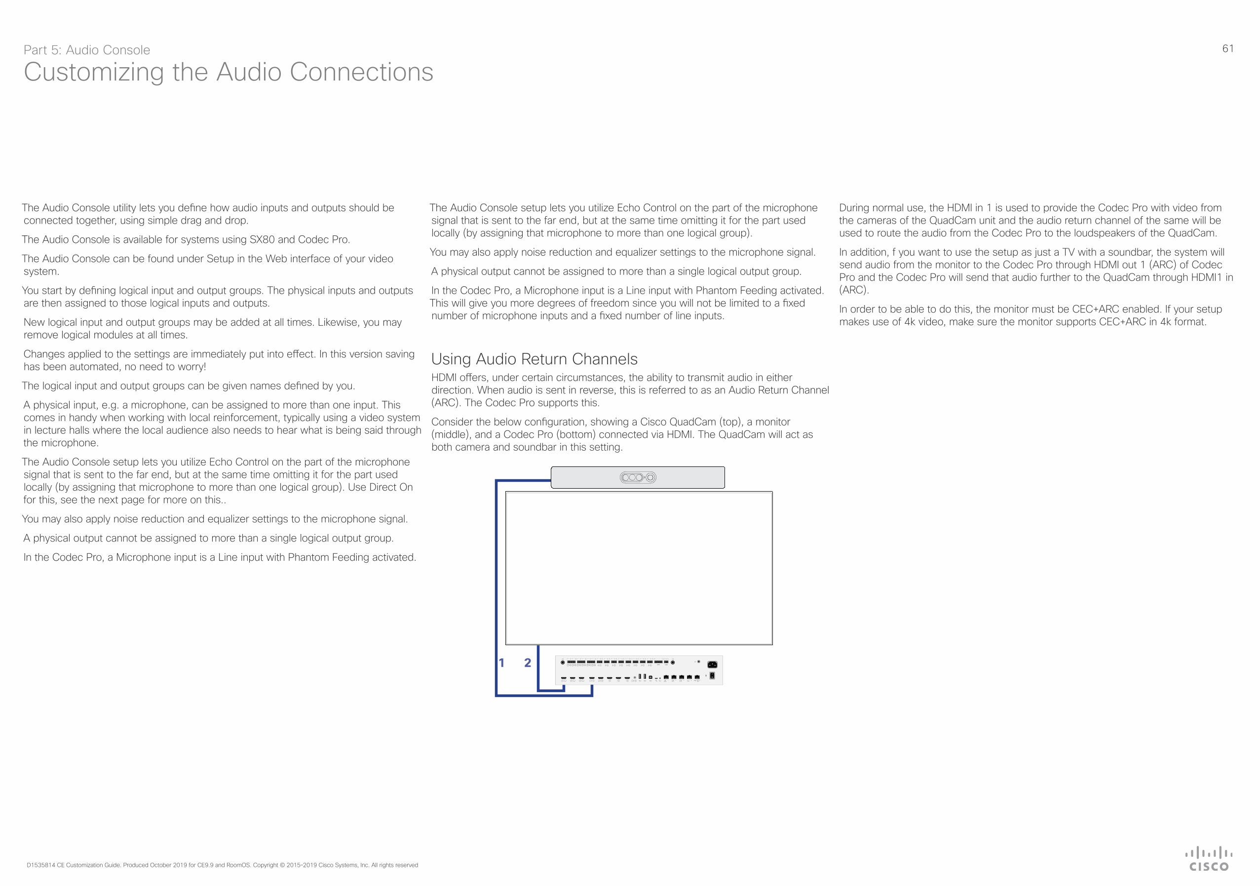
61
D1535814 CE Customization Guide. Produced October 2019 for CE9.9 and RoomOS. Copyright © 2015–2019 Cisco Systems, Inc. All rights reserved
Customizing the Audio ConnectionsPart 5: Audio Console
The Audio Console utility lets you define how audio inputs and outputs should be connected together, using simple drag and drop.
The Audio Console is available for systems using SX80 and Codec Pro.
The Audio Console can be found under Setup in the Web interface of your video system.
You start by defining logical input and output groups. The physical inputs and outputs are then assigned to those logical inputs and outputs.
New logical input and output groups may be added at all times. Likewise, you may remove logical modules at all times.
Changes applied to the settings are immediately put into effect. In this version saving has been automated, no need to worry!
The logical input and output groups can be given names defined by you.
A physical input, e.g. a microphone, can be assigned to more than one input. This comes in handy when working with local reinforcement, typically using a video system in lecture halls where the local audience also needs to hear what is being said through the microphone.
The Audio Console setup lets you utilize Echo Control on the part of the microphone signal that is sent to the far end, but at the same time omitting it for the part used locally (by assigning that microphone to more than one logical group). Use Direct On for this, see the next page for more on this..
You may also apply noise reduction and equalizer settings to the microphone signal.
A physical output cannot be assigned to more than a single logical output group.
In the Codec Pro, a Microphone input is a Line input with Phantom Feeding activated.
The Audio Console setup lets you utilize Echo Control on the part of the microphone signal that is sent to the far end, but at the same time omitting it for the part used locally (by assigning that microphone to more than one logical group).
You may also apply noise reduction and equalizer settings to the microphone signal.
A physical output cannot be assigned to more than a single logical output group.
In the Codec Pro, a Microphone input is a Line input with Phantom Feeding activated. This will give you more degrees of freedom since you will not be limited to a fixed number of microphone inputs and a fixed number of line inputs.
Using Audio Return ChannelsHDMI offers, under certain circumstances, the ability to transmit audio in either direction. When audio is sent in reverse, this is referred to as an Audio Return Channel (ARC). The Codec Pro supports this.
Consider the below configuration, showing a Cisco QuadCam (top), a monitor (middle), and a Codec Pro (bottom) connected via HDMI. The QuadCam will act as both camera and soundbar in this setting.
During normal use, the HDMI in 1 is used to provide the Codec Pro with video from the cameras of the QuadCam unit and the audio return channel of the same will be used to route the audio from the Codec Pro to the loudspeakers of the QuadCam.
In addition, f you want to use the setup as just a TV with a soundbar, the system will send audio from the monitor to the Codec Pro through HDMI out 1 (ARC) of Codec Pro and the Codec Pro will send that audio further to the QuadCam through HDMI1 in (ARC).
In order to be able to do this, the monitor must be CEC+ARC enabled. If your setup makes use of 4k video, make sure the monitor supports CEC+ARC in 4k format.
1 2

62
D1535814 CE Customization Guide. Produced October 2019 for CE9.9 and RoomOS. Copyright © 2015–2019 Cisco Systems, Inc. All rights reserved
A few things to note:
The Codec Pro offers Audio Return Channels (ARC) as additional choices (see the previous page for more on this).
In the Codec Pro, a Microphone input is a Line input with Phantom Feeding activated.
In local reinforcement scenarios, make sure you set the Microphone(s) to Direct to bypass extra processing like Echo Control. This will minimize latency and also serve to avoid that the Master volume control also affects the volume of the local presenter.
Expand the logical group to gain access to this, as shown above.
The pool of physical Input connectors available.
This is the pool of physical Output connectors not yet used. They are therefore considered inactive.
The physical Input connectors are assigned to logical Input groups. These logical Input groups are created by you.
The name of a logical group is specified by you when clicking on
New input group.
A given physical Input connector may be assigned to more than one logical group.
Use Drag and Drop.
To remove a group or a member of a group hover the mouse over the group or
member. An X will appear. Click on this to remove the item.
The logical Output groups are similar to the logical Input groups, but a physical Output cannot be assigned to more than one logical Output group.
Click here and drag over here to establish a connection between an Input and an Output.
To delete a connection or adjust its gain, right-click on
the “cable”.
Equalizer lets you choose among up to 8 predefined equalizer settings (or none, i.e. Off).This version of the Audio Console offers a graphical tool to set up the equalizer, see the next page for more on this.
Gain access to the equalizer setup.
The Audio Console can be found under Setup in the Web interface of your video system.
A member of a logical group may be expanded to gain access to setup details:
Expand the Logical group rather than the individual members of the Logical group when using it for
local reinforcement.
For the Codec Pro and the Room 70 G2 there is an automatic mode available. This mode will create a preset of connections based on connected devices detected. You may then modify this to your liking.
We recommend that you set Delay Mode to Fixed to avoid potential delay caused by external screens.
For local reinforcement scenarios, set microphones to Direct, see text below.
The Audio Console PanelPart 5: Audio Console
Use this feature in scenarios with e.g. a presenter’s microphone. This mic will be muted unless the associated camera (the one filming the presenter) actually sends video, provided that you have set up a camera/mic combination this way.
Gain access to the
equalizer setup.

63
D1535814 CE Customization Guide. Produced October 2019 for CE9.9 and RoomOS. Copyright © 2015–2019 Cisco Systems, Inc. All rights reserved
Setting Up the EqualizerPart 5: Audio Console
There are 8 user-definable parametric equalizer settings
available.
A setting consists of up to 6 sections, each of which has its own filter type,
gain, center/crossover frequency and Q value.
Each section is shown with its own color, while the white line shows the
combined frequency response of the equalizer.
To activate or deactivate a filter section, click here.
The filter types available
Gain access to the equalizer
from here or here.
Here you define which of the 8 equalizer settings to
apply (No. 5 in this example).
Next setting (if applicable)
Previous setting (if applicable)
Value space for the Gain setting is 0 dB ±20 dB.
Value space for Frequency is 20–20 000 Hz.
Value space for Q is 0.1–10.0.
The effect of altering any of the parameters will immediately become visible in the graph.
Your settings are saved automatically, no need to click a Save button anymore!

64
D1535814 CE Customization Guide. Produced October 2019 for CE9.9 and RoomOS. Copyright © 2015–2019 Cisco Systems, Inc. All rights reserved
A member of a logical group may be expanded to gain access to setup details specific for that
member only.
You may expand a Logical Group to get access to settings on a group level.
In local reinforcement scenarios, make sure you set the Microphone(s) to Direct On to bypass extra processing like Echo Control. This will minimize latency and also serve to avoid that the Master volume control also affects the volume of the local presenter. For other use cases leave it Off.
Mixer Mode can be GainShared or Fixed. If GainShared the summed level of the microphone signals will never exceed a certain value (but their individual offsets will be retained). In Fixed Mode the levels are just summed together.
Mute the entire Logical Group.
Enable/Disable AGC (Automatic Gain Control)
applying to the entire Logical Group.
Channels can be 1 (mono) or 2 (stereo).
Applies to Codec Plus only. For Microphone inputs
leave this setting at 1 for the SX80.
Phantom power can be switched off when microphones are used with a
preamplifier providing line level signals without the need for power submitted
through the microphone cable.
Make sure you reduce the gain (typically by 40 dB or more) if you decide to use
a Mic input as a Line input.
In the Codec Pro, a Microphone input is a Line input with Phantom Feeding
activated.
Mode: A microphone can be set to On or Off.
The term Level should be interpreted as Gain here.
If Channels has been set to 2 (on Group level), you may use the Channel setting here to specify whether this particular microphone belongs to the group of left channel microphones, or the group of right channel microphones (Codec Pro only).
The SX80 cannot do this with microphones, but it can for any other input source. Codec Pro can do this with any type of input source (Incl microphones). See also text above.
If the entire Logical Group has been set to Direct on Group level, Echo Control will be set to N/A.
Noise Reduction: Setting this to On will reduce any continuous noise (like from fans) present in the room. Impulsive noise will not be reduced.
Mute on Inactive Video: Use this feature in scenarios with e.g. a presenter’s microphone. This mic will be muted unless the associated camera (the one filming the presenter) actually sends video, provided that you have set up a camera/mic combination this way.
Equalizer is discussed on the previous page.
A Few Words on Channels and Inputs on the SX80For other input sources than microphones, the SX80 provides the option of setting stereo mode, similar to the Codec Pro (see below). Note that any input source, such as Microphones, Line or HDMI inputs may be included in any Input group, as can be seen from the name of the group at left (Microphone/Line). Also note that non-microphone inputs cannot be subject to echo control. If you use a microphone with a preamplfier connected to one of the Line inputs of the SX80, you won’t be able to expose it to the echo control. In such cases you should consider external echo controls, although we do not recommend the use of such devices.
More On Setting Up the MicrophonesPart 5: Audio Console

65
D1535814 CE Customization Guide. Produced October 2019 for CE9.9 and RoomOS. Copyright © 2015–2019 Cisco Systems, Inc. All rights reserved
Cisco contacts
On our web site you will find an overview of the worldwide Cisco contacts.
Go to: http://www.cisco.com/go/offices
Corporate HeadquartersCisco Systems, Inc.
170 West Tasman Dr.San Jose, CA 95134 USA
Intellectual property rights
THE SPECIFICATIONS AND INFORMATION REGARDING THE PRODUCTS IN THIS MANUAL ARE SUBJECT TO CHANGE WITHOUT NOTICE. ALL STATEMENTS, INFORMATION, AND RECOMMENDATIONS IN THIS MANUAL ARE BELIEVED TO BE ACCURATE BUT ARE PRESENTED WITHOUT WARRANTY OF ANY KIND, EXPRESS OR IMPLIED. USERS MUST TAKE FULL RESPONSIBILITY FOR THEIR APPLICATION OF ANY PRODUCTS.
THE SOFTWARE LICENSE AND LIMITED WARRANTY FOR THE ACCOMPANYING PRODUCT ARE SET FORTH IN THE INFORMATION PACKET THAT SHIPPED WITH THE PRODUCT AND ARE INCORPORATED HEREIN BY THIS REFERENCE. IF YOU ARE UNABLE TO LOCATE THE SOFTWARE LICENSE OR LIMITED WARRANTY, CONTACT YOUR CISCO REPRESENTATIVE FOR A COPY.
The Cisco implementation of TCP header compression is an adaptation of a program developed by the University of California, Berkeley (UCB) as part of UCB’s public domain version of the UNIX operating system. All rights reserved. Copyright © 1981, Regents of the University of California.
NOTWITHSTANDING ANY OTHER WARRANTY HEREIN, ALL DOCUMENT FILES AND SOFTWARE OF THESE SUPPLIERS ARE PROVIDED “AS IS” WITH ALL FAULTS. CISCO AND THE ABOVE-NAMED SUPPLIERS DISCLAIM ALL WARRANTIES, EXPRESSED OR IMPLIED, INCLUDING, WITHOUT LIMITATION, THOSE OF MERCHANTABILITY, FITNESS FOR A PARTICULAR PURPOSE AND NONINFRINGEMENT OR ARISING FROM A COURSE OF DEALING, USAGE, OR TRADE PRACTICE.
IN NO EVENT SHALL CISCO OR ITS SUPPLIERS BE LIABLE FOR ANY INDIRECT, SPECIAL, CONSEQUENTIAL, OR INCIDENTAL DAMAGES, INCLUDING, WITHOUT LIMITATION, LOST PROFITS OR LOSS OR DAMAGE TO DATA ARISING OUT OF THE USE OR INABILITY TO USE THIS MANUAL, EVEN IF CISCO OR ITS SUPPLIERS HAVE BEEN ADVISED OF THE POSSIBILITY OF SUCH DAMAGES.
Any Internet Protocol (IP) addresses and phone numbers used in this document are not intended to be actual addresses and phone numbers. Any examples, command display output, network topology diagrams, and other figures included in the document are shown for illustrative purposes only. Any use of actual IP addresses or phone numbers in illustrative content is unintentional and coincidental.
All printed copies and duplicate soft copies are considered un-Controlled copies and the original on-line version should be referred to for latest version.
Cisco has more than 200 offices worldwide. Addresses, phone numbers, and fax numbers are listed on the Cisco website at www.cisco.com/go/offices.
Cisco and the Cisco logo are trademarks or registered trademarks of Cisco and/or its affiliates in the U.S. and other countries. To view a list of Cisco trademarks, go to this URL: www.cisco.com/go/trademarks. Third-party trademarks mentioned are the property of their respective owners. The use of the word partner does not imply a partnership relationship between Cisco and any other company. (1110R)