cisco network-based intrusion detection—functionalities ... · it addresses mitigation...
TRANSCRIPT

Server Farm Security in the BusineOL-9015-01
C H A P T E R 8
Cisco Network-Based Intrusion Detection—Functionalities and ConfigurationThis chapter highlights the need for and the benefits of deploying network-based intrusion detection in the data center. It addresses mitigation techniques, deployment models, and the management of the infrastructure.
Intrusion detection systems help data centers and other computer installations prepare for and deal with electronic attacks. Usually deployed as a component of a security infrastructure with a set of security policies for a larger, comprehensive information system, the detection systems themselves are of two main types. Network-based systems inspect traffic “on the wire” and host-based systems monitor only individual computer server traffic.
Network intrusion detection systems deployed at several points within a single network topology, together with host-based intrusion detection systems and firewalls, can provide a solid, multi-pronged defense against both outside, Internet-based attacks, and internal threats, including network misconfiguration, misuse, or negligent practices. The Cisco Intrusion Detection System (IDS) product line provides flexible solutions for data center security.
Note This chapter is complemented by Chapter 7, “Traffic Capturing for Granular Traffic Analysis,” and by Chapter 9, “Deployment of Network-Based IDS Sensors and Integration with Service Modules.”
This chapter includes the following sections:
• Network-based Intrusion Detection Overview
• The Need for Intrusion Detection Systems
• Solution Topology
• Cisco IDS
• Methods of Network Attack
• Cisco IDS Attack Mitigation Techniques
• Configuring the Network Sensor
• Configuring Traffic Capture
• Small-to-Medium Management Tools
• Enterprise Class Management Tools
8-1ss Ready Data Center Architecture v2.1
Chapter 8 Cisco Network-Based Intrusion Detection—Functionalities and Configuration Network-based Intrusion Detection Overview
• Tuning Sensors
• Cisco Product Matrix
Network-based Intrusion Detection OverviewData centers are experiencing an increase in network security threats resulting in the loss of revenue, productivity, and business opportunity. Comprehensive security policies and architectures that include network-based intrusion detection systems (NIDS) are a means to combat this expanding threat. NIDS perform analysis of all traffic passing on a network segment or subnet. This chapter provides insight into the need for NIDS in the data center and the benefits of a properly deployed, configured, and managed system.
This chapter also describes the techniques used by “electronic thieves” and attackers when attacking networks, and the methods they use to avoid detection. It also explains the methods that Cisco IDS products employ to detect and thwart network intrusion. The goal is to mitigate the impact of these attacks and improve network visibility. The Cisco IDS product line provides a flexible range of deployment options for securing modern network architectures. This chapter also reviews the Cisco management alternatives available in the data center for creating a secure, efficient, and thorough intrusion protection solution.
The Need for Intrusion Detection SystemsData centers enable the consolidation of critical computing resources in controlled environments under centralized management. They allow enterprises to operate around the clock, according to their business needs. A data center provides the following services to support application availability:
• Infrastructure—Layer 2, Layer 3, intelligent network services, and data center transport
• Application optimization services—Content switching, caching, SSL offloading, and content transformation
• Storage—Consolidation of local disks, network attached storage, and storage area networks (SANs)
• Security—Access control lists (ACLs), firewalls, and intrusion detection systems
• Management—Management devices applied to the elements of the architecture
When a malfunction occurs in the data center and critical business services are not available, the bottom line usually suffers. Security policies must be developed and implemented to mitigate vulnerabilities and assure data center resilience against external and internal threats.
You should deploy security services in the data center as an end-to-end, layered solution consisting of firewalls, access lists, and intrusion prevention and detection systems. You should implement security policies to prevent the following security vulnerabilities:
• Unauthorized access
• Denial of service (DoS)
• Network reconnaissance
• Viruses and worms
• IP spoofing
• Layer 2 attacks
8-2Server Farm Security in the Business Ready Data Center Architecture v2.1
OL-9015-01

Chapter 8 Cisco Network-Based Intrusion Detection—Functionalities and Configuration Solution Topology
Applications are targets in the data center. Packet inspectors, such as firewalls, are not enough to protect business critical applications from external and internal threats. The devices employed to enforce security policies must scrutinize the protocols and application data traversing the network. NIDS satisfy this requirement by identifying harmful network traffic and performing the appropriate action based on the established security policy. Possible actions include logging, shunning, or resetting traffic that is identified as detrimental to the network.
Solution TopologyThe enterprise data center is designed to satisfy the business and application requirements of the organization, and is a complex structure segmented into service and security domains. The following service domains exist in the enterprise data center:
• Internet gateway
• Internet edge
• Extranet data center
• Internet server farm
• Intranet data center
Data center networks have multiple points of vulnerability that are susceptible to attack. To fortify this architecture, strategically position NIDS to protect all the areas within the data center.
Figure 8-1 indicates the multiple network vulnerability points that the enterprise security policy must address across service domains. The deployment of NIDS is essential to a comprehensive security implementation.
8-3Server Farm Security in the Business Ready Data Center Architecture v2.1
OL-9015-01

Chapter 8 Cisco Network-Based Intrusion Detection—Functionalities and Configuration Solution Topology
Figure 8-1 Enterprise Data Center—Network Vulnerability Points
NIDS monitor these domains and provide protection from various threats. Network sensors (intrusion detection devices) are essential to building a secure enterprise data center architecture. For example, sensors can protect critical assets in the intranet data center from internal threats, such as disgruntled employees. Network sensors can also provide an extra level of safety in the extranet domain by monitoring traffic between partners. Cisco recommends the deployment of network intrusion sensors in the following locations:
• Behind firewalls
• On demilitarized zone (DMZ) segments that house public servers (web, FTP, Domain DNS, or e-commerce)
• Behind VPN concentrators for monitoring unencrypted virtual private network (VPN) traffic
• On segments that house corporate servers or other intranet services that are defined as sensitive in the security policy
• On segments that house network and security management servers
1043
56
Internet Gateway
Internet Edge
ExtranetData Center
Campus Core
InternetSP1
PrivateWAN
SP2PSTN
RemoteOffice
Or Or
DMZ
CorporateInfrastructure
PartnersWAN
InternetServerFarm
VPN
Intranet Data CenterNetwork vulnerability points
8-4Server Farm Security in the Business Ready Data Center Architecture v2.1
OL-9015-01

Chapter 8 Cisco Network-Based Intrusion Detection—Functionalities and Configuration Cisco IDS
• On the corporate intranet where critical resources are located
• At corporate extranet junction points between the campus network and branch networks as well as between the enterprise and partner networks
Cisco IDSCisco comprehensive end-to-end security products include NIDS to meet the needs of different organizations. These intrusion detection security solutions provide the following services:
• Accurate threat detection
• Intelligent threat investigation
• Ease of management
• Flexible deployment options
The deployment options include the following:
• Cisco Intrusion Detection System 4200 Security Appliance (Cisco IDS)
• Cisco Intrusion Detection System Module for the Catalyst 6500 Series switches (Cisco IDSM and IDSM-2)
• Cisco Intrusion Detection System Module for the 2600/3600/3700 series of routers (NM-CIDS)
Each of these network sensors utilizes the Cisco IDS software, which ensures a secure network environment through extensive inspection of potential threats. Cisco IDS software is available as a standalone appliance or integrated into switches, routers, and firewalls.
Enterprise-level management and monitoring is enabled through browser-based user interfaces. This provides a simplified and consistent user experience, and delivers powerful analytical tools that allow for a rapid and efficient response to threats. Secure access to a command-line interface (CLI) is also supported.
Methods of Network AttackThis section includes the following topics:
• Types of Attacks
• IDS Evasion Techniques
Network attackers perform reconnaissance to identify and investigate target systems before striking. Reconnaissance may provide the following information to the attacker:
• Host detection
• Network topology
• ACL detection
• Packet filter detection
• Operating system fingerprinting
• Contact information
8-5Server Farm Security in the Business Ready Data Center Architecture v2.1
OL-9015-01

Chapter 8 Cisco Network-Based Intrusion Detection—Functionalities and Configuration Methods of Network Attack
ICMP, TCP, UDP, or SNMP sweeps and scans are methods of intelligence gathering used in reconnaissance. Attackers also spoof IP addresses and use social engineering to obtain confidential network information. The objective of network reconnaissance is to identify security vulnerabilities and misconfigurations for future exploits. There are many tools available to help the attacker scout the network, such as NMAP, AMAP, HPING2, and SNMPWALK.
NIDS notify administrators when attackers are investigating or attacking their networks. NIDS devices are installed in strategic areas to provide comprehensive coverage of all network segments. Online groups of attackers, often referred to as “black hats”, have developed common methods to attack data centers and bypass these security services. The following sections describe prevalent network attacks and detection avoidance techniques used by black hat intruders.
Types of AttacksThis section briefly describes some of the most common types of network attacks.
Buffer Overflow
The goal of a buffer overflow attack is to overwrite sections of memory on a server or desktop, with specific commands executed by the system on behalf of the attacker. These malicious commands generally create DoS conditions or permit remote system access for the attacker.
The buffer overflow attack exploits the lack of secure software design by developers. Developers must limit the size of the data sent to the buffer or risk crashing the stack. The primary security flaw is a lack of boundary-checking logic for application input or application-generated data. Application data is written to and subsequently accessible in the memory stack. An overflow condition exists when the data exceeds the size of the buffer.
Techniques used to identify systems susceptible to buffer overflows include debugger tools, trial and error, and brute force attacks. The hacker modifies the specifics of the attack for the target application and operating system. Lengthy URL strings are one common input value used by attackers to overflow system buffers.
Worms
A worm is a computer program that replicates itself on the local host or throughout the network but does not infect other program files on the system. This type of attack may propagate itself through e-mail attachments or Internet Relay Chat (IRC) exchanges. Worms are typically undetected until the consumption of significant network resources occurs, primarily processor utilization or bandwidth, which denies services to other application or network tasks.
Worms designed to identify confidential information on the compromised system are a particular threat. The worm may search files for key words such as “finance”, “SSN”, or “credit” and then forward the file information to the attacker. Worms may also create DoS conditions, such as the Code Red worm that exploited the buffer overflow vulnerabilities in Microsoft IIS software.
Trojans
To obtain information without authorization, attackers often invoke the use of Trojan horse programs. These programs pretend to be a benign application but are, in reality, a threat to system security and organizational data. A Trojan does not replicate like a virus or transmit itself like a worm to other network devices. Trojan horse programs launch DoS attacks, erase local disk drives, or permit system
8-6Server Farm Security in the Business Ready Data Center Architecture v2.1
OL-9015-01

Chapter 8 Cisco Network-Based Intrusion Detection—Functionalities and Configuration Methods of Network Attack
hijacking. FTP and WWW archives are areas where victims may unknowingly download these malicious files. Peer-to-peer file exchanges via IRC or e-mail attachments are other methods to import this hidden security risk. Files with the extensions of “exe”, “vbs”, “com”, or “bat” can potentially carry Trojan horse programs into your network. Back Orifice is a common Trojan horse utility.
CGI Scripts
The Common Gateway Interface (CGI) enables the creation of dynamic and interactive web pages. Web servers use CGI to permit interaction between server programs and web users. The capacity to interact with the user is both a powerful feature and a significant security vulnerability. Attackers can exploit the programming mistakes present in CGI scripts to gain access to system files. If a developer fails to verify application input, a CGI script can allow an attacker to perform backtracking or shell-based vulnerability attacks. The Nimda worm, for example, used a flaw in the CGI implementation of Microsoft IIS web servers to issue the root.exe command and infect other devices.
Backtracking is the practice of adding the directory label “..” to file pathnames. A common mistake made by programmers is failing to verify that the input data does not contain the backtrack characters. Attackers can use this vulnerability to gain access to files that should not be available to the web service.
The shell attack works on UNIX operating systems to gain root shell access. This attack is typically performed by adding the pipe “|” character to the end of application input to force the execution of malicious commands.
Protocol Specific Attacks
Protocol specifications describe the rules and procedures that devices obey when performing network activities. Exploitations of ARP, IP, TCP, UDP, ICMP, and application protocols are the result of weaknesses in protocol design. Protocol threats fall under two categories: protocol impersonation (spoofing) or malformed protocol messages. The intent of protocol attacks is to deceive, compromise, and/or crash the target device.
To bypass application security, attackers can use protocol analyzers and manipulate the standard methods of communication. For instance, Address Resolution Protocol (ARP) does not require authentication of its messages. Hackers use this flaw to perform “man-in-the-middle” attacks using gratuitous ARP. The attacker impersonates the default gateway for a network segment and is then able to capture all traffic on that segment.
Traffic Flooding
Traffic flooding is an attack technique that targets the capacity of NIDS to manage heavy traffic loads and to screen for potential attacks. If an attacker can create a congested environment, the NIDS must analyze and report on large amounts of data. An intruder may execute an attack under these conditions, hoping it will be unnoticed by the security devices and security personnel amidst the network chaos. Desensitizing the network security infrastructure is the primary goal of this attack. Attack tools such as Stick and Snot consume NIDS processing power and may be used as part of a traffic flooding attack.
8-7Server Farm Security in the Business Ready Data Center Architecture v2.1
OL-9015-01

Chapter 8 Cisco Network-Based Intrusion Detection—Functionalities and Configuration Methods of Network Attack
IDS Evasion TechniquesThis section describes the methods that attackers may use to evade the protections provided by NIDS.
Fragmentation
IP performs fragmentation by dividing one large packet into smaller packets. IP fragmentation provides a flexible method for data to traverse the networks using different media types, which have different maximum transmission units (MTU). The recipient of the fragmented packets must reassemble the data payload before forwarding it to the Application layer. Properly formed IP fragments have the following attributes:
• Shared fragment ID
• Offset information in relation to the original, unfragmented packet
• Length of the data in the fragment
• Indication of other fragments to follow
To analyze properly fragmented traffic, the network sensor must reconstruct these packets in the same manner as the destination host. The rebuilding of packets requires the sensor to keep the data in memory and compare the information against its active signature list. A signature is a known pattern of attacks for which the network sensor looks when monitoring traffic. This procedure is processor intensive. Techniques used by attackers to evade detection by masking attacks as legitimate traffic include fragmentation overlap, overwrite, and timeouts.
Fragmentation overlap requires that packet fragments overwrite portions of previously sent packets. The reassembly of these two fragments creates a malicious packet on the host that evades network detection. Attacks that use the fragmentation overlapping technique include the teardrop fragmentation overlap attacks. For example, the fragmentation overlap attack can force a change in the destination port from 80 to 23 to permit Telnet access to the target device (see Figure 8-2).
Figure 8-2 Typical Fragmentation Overlap Attack
Overwriting previously sent fragments is another way to exploit fragmentation. The intruder hides an attack among a number of packets and overwrites the unnecessary fragments to form a malicious packet (see Figure 8-3). Fragrouter is a tool that attackers often use to fragment IP packets.
Figure 8-3 Fragmentation—Overwrite
1043
57
Fragment 1
Source IP X:13245 Dest. IP Y:80
Fragment 2
23+ Fragment 1
Source IP X:13245 Dest. IP Y:
Fragment 2
23
1043
58
Packet Fragment 3
=+Fragmented Data=.x?(buffer overflow)
Packet Fragment 1
GET foo+X Packet Fragment 2
Fragmented Data=nothinguseful
Reassembled Packet
GET foo.x?(buffer overflow)
8-8Server Farm Security in the Business Ready Data Center Architecture v2.1
OL-9015-01

Chapter 8 Cisco Network-Based Intrusion Detection—Functionalities and Configuration Methods of Network Attack
The network intrusion sensor must maintain state for all of the traffic on the segment it is monitoring. The length of time that the sensor can maintain state information may be shorter than the time that the destination host can maintain state information. Attackers try to take advantage of any limitation in the sensor by sending attack fragments over a long period.
Flooding
Network intrusion devices themselves are sometimes the targets of DoS attacks. The attacker launches the attack to overwhelm the sensor and cause a fail-open situation. A common technique to generate a flood situation is spoofing legitimate UDP or ICMP traffic. The traffic flood hides the true intent of the attacker like the proverbial “needle in the haystack”.
Obfuscation
To evade detection, attackers employ a technique called obfuscation, which is the practice of concealing an attack by translating the data into a different character set. Obfuscation tries to exploit any weakness in the signature set supported on the sensor and its ability to replicate the way the destination host interprets application data.
For example, the HTTP request, “GET /etc/passwd” in hexadecimal notation is as follows:
GET %65%74%63/%70%61%73%73%77%64
Or
GET %65%74%63/%70a%73%73%77d
Successful detection of this request requires that the sensor supports the hexadecimal encoding format or includes these hexadecimal strings in its set of attack signatures.
Unicode presents particular challenges for NIDS. Unicode/UTF-8 standard allows one character to be represented in several different formats. In addition, applications may use different Unicode implementations for decoding. Attackers may also double-encode data, exponentially increasing the number of signatures required to catch the attack.
Encryption
Intrusion detection devices must be able to monitor and interpret many traffic types to alert the enterprise to security threats. HTTP, FTP, and ARP are a few examples. However, monitoring encrypted traffic creates a problem for sensors. Encryption provides several security services, including data integrity, non-repudiation, and data privacy. Attackers utilize these security features to evade detection and hide attacks that may threaten a network. The Secure Socket Layer (SSL), which takes advantage of encryption, is a traffic type that blinds the sensor to possible attacks against web servers because the sensor is unable to read the encrypted data. Delivering malicious code within an SSL session is a powerful method of attacking network resources such as secure web servers.
Asymmetric Routing
The path through the network that the attack uses can reduce the effectiveness of intrusion detection devices. If multiple routes exist to a target device, the attacker can distribute the attack packets to evade detection despite the presence of sensors on each network segment. Because of the asymmetric routing in the network, each individual sensor is unaware of the complete attack package. Symmetric routing allows a single sensor to see all of the activity on a network segment, which provides a better opportunity for detecting an attack.
8-9Server Farm Security in the Business Ready Data Center Architecture v2.1
OL-9015-01

Chapter 8 Cisco Network-Based Intrusion Detection—Functionalities and Configuration Cisco IDS Attack Mitigation Techniques
Cisco IDS Attack Mitigation TechniquesThis section describes the types of signature analysis performed by Cisco NIDS, and includes the following topics:
• Simple Pattern Matching
• Session-Aware Pattern Matching
• Context-Based Signatures
• Protocol Decode Analysis
• Heuristic Analysis
• Traffic Anomaly Analysis
Cisco sensors counteract evasive and destructive attack techniques by accurately identifying known attacks and limiting the occurrences of false alarms. The network designer should route traffic through network segments monitored by Cisco sensors to take advantage of this capability.
Signature-based analysis allows one to monitor a network segment. Detecting worms, scans, or Application layer attacks is possible by examining the packet header and payload. By comparing captured network traffic to an extensive set of predefined signatures, Cisco sensors can detect network attacks such as fragmentation, obfuscation, and buffer overflows.
These signatures are stored in the Cisco Secure IDS Network Security Database (NSDB). The Cisco sensor compares each packet to the NSDB. The NSDB is not static; updates are regularly available online to keep it current with the latest attacks. You can also add custom signatures to thwart new threats identified in your network.
When packet information matches an active signature, the sensor responds in any of the following ways that you choose to enable:
• Logs the event (IP logging)
• Forwards the event to an NIDS manager
• Performs a TCP reset (if applicable)
• Shuns the traffic through dynamic configuration of other network devices
These responses are applicable to all triggering events, which includes any packet or sequence of packets that the sensor identifies as suspect or dangerous.
Simple Pattern MatchingThis is the most basic of pattern matching techniques Cisco sensors employ. Simple pattern matching detects a sequence of bytes contained in one packet captured by the sensor.
Session-Aware Pattern MatchingSession-aware pattern matching requires the sensor to maintain state information on the TCP streams present in the network. Accurate detection is dependent on the sensor buffering and interpreting the complete conversation across packet boundaries. The sensor orders the packets appropriately before applying signature rules to address the issue of fragmentation.
8-10Server Farm Security in the Business Ready Data Center Architecture v2.1
OL-9015-01

Chapter 8 Cisco Network-Based Intrusion Detection—Functionalities and Configuration Cisco IDS Attack Mitigation Techniques
Context-Based SignaturesContext-based signature analysis is another approach used to combat malicious activity. This type of examination requires the sensor to understand the circumstance of the conversation and determine the appropriateness of certain patterns within the packet. For example, attacks against a web server often occur in the URL request. The sensor starts looking for buffer overflow signatures after the client sends the HTTP request. The Cisco sensor must be aware of the flow and parameters of each traffic type being searched for context-based signatures.
Protocol Decode AnalysisProtocol decode analysis decodes the various elements in a series of packets in the same manner as do the client or server in the conversation. Full protocol decode allows other analysis tools to be used in the validation process. Using signatures to detect certain patterns within the protocol is a common practice.
Protocol decode compares the traffic patterns with the specifications outlined in the RFC documentation. Traffic found to be non-compliant with the RFC causes logging and/or alerting the network administrator of a possible threat. This type of analysis requires the sensor to be protocol-aware. Cisco sensors understand the following protocols:
• DNS
• SMB
• RPC
• HTTP (with full de-obfuscation)
• SMTP
• SNMP
• FTP
• ICMP
• TFTP
• Telnet
• SSH
• TFTP
• IDENT
• POP
• IMAP
• LPD
Heuristic AnalysisCisco sensors employ heuristic analysis to determine network traffic statistics. A sensor applies logical algorithms to determine the type of traffic traversing the network (learning through discovery). Deviation from the standard traffic statistics triggers an event. The sensor “learns” when you tune the algorithms to reduce the number of false positives and to more accurately monitor the network.
8-11Server Farm Security in the Business Ready Data Center Architecture v2.1
OL-9015-01

Chapter 8 Cisco Network-Based Intrusion Detection—Functionalities and Configuration Configuring the Network Sensor
A common example that demonstrates heuristics at work is the detection of a ping flood. If the number of pings received during any one period exceeds the statistical average number of pings, an event is triggered. Cisco sensors use the expected network behavior to validate traffic patterns. Interpreting complex relationships through heuristics is sometimes the only way to detect in-depth attacks.
Traffic Anomaly AnalysisCisco intrusion sensors are able to detect deviations in the normal traffic patterns associated within a network segment, where normal is the standard, well-behaved traffic expected on your network. Traffic anomaly analysis requires you to define thresholds for interesting traffic types. After you define the limits, the sensor responds to traffic patterns exceeding the threshold by triggering an event. Traffic anomaly analysis can detect any abnormal events, such as the following:
• Flood of UDP packets, which might be the beginning of a DoS attack
• Sudden increase in ICMP traffic, which is typical of reconnaissance by an attacker
• Abnormally large web request, which is often associated with a buffer overflow attack
Traffic anomaly analysis is most effective in a relatively static environment. Your ability to define the normal traffic patterns is the key to its effectiveness. The data center environment is well-suited to traffic anomaly detection because the applications can be controlled and characterized.
Traffic anomaly analysis may be able to detect attacks without a known attack signature by successfully identifying abnormal traffic conditions. However, when the sensor detects abnormal traffic, the actual source of the traffic is unclear. Traffic anomaly analysis indicates only the possibility of an attack. The network administrator must interpret the sensor data to determine whether the abnormal network activity is authorized.
Configuring the Network SensorYou use the CLI to perform the initial configuration of a Cisco intrusion detection sensor. There are three methods to access the Cisco IDS software CLI:
• Telnet or SSH session to the sensor
• Serial connection to the local console interface
• Monitor and keyboard
Cisco IDS sensors are available as the following hardware types:
• Cisco Intrusion Detection System 4200 Security Appliance (Cisco IDS)
• Cisco Intrusion Detection System Module for the Catalyst 6500 Series of switches (Cisco IDSM and IDSM-2)
• Cisco Intrusion Detection System Module for the 2600/3600/3700 Series of routers (NM-CIDS)
The IDS modules (IDSM) are blades that plug into a Catalyst 6500. An IDSM does not have a network interface of its own; it connects to the Catalyst 6500 through the backplane.
To configure Cisco IDSM and IDSM-2 using CatOS, enter the following commands from the CLI prompt: Console> (enable) session module_number.
To configure Cisco IDSM and IDSM-2 using Cisco Native IOS, enter the following commands from the CLI prompt: Router# session slot slot_number processor 1
8-12Server Farm Security in the Business Ready Data Center Architecture v2.1
OL-9015-01

Chapter 8 Cisco Network-Based Intrusion Detection—Functionalities and Configuration Configuring Traffic Capture
To define the basic system parameters required by the sensor, complete the following steps:
Step 1 When prompted by the system, enter the username and password.
The default username and password for the sensors are both cisco. When you first log in, the system prompts you to change the default password. The new password must be at least eight characters in length and must not occur in a dictionary or be based on a word in a dictionary.
Step 2 Enter the following command:
ids# setup
Step 3 Respond to the prompts and configure the following settings for the sensor:
• Hostname
• IP address
• Net mask
• Default gateway
• Telnet server status (default=disabled)
• Web server port (default=443)
• Network Time Protocol (NTP) parameters
Step 4 Specify an access list of allowed networks for remote management access.
You can now access the sensor over the network to which it is connected. To complete the rest of the sensor configurations, you can use the tools discussed in Enterprise Class Management Tools, page 8-19. You can also use the CLI to perform the rest of the configuration.
Configuring Traffic CaptureA Cisco intrusion detection sensor passively listens in promiscuous mode to network traffic that is replicated to it. This section describes several methods to forward network traffic to a sensor that a host Catalyst 6500 can use, and includes the following topics:
• Configuring SPAN
• Configuring VACLs
• Configuring RSPAN with VACL
• Configuring MLS IP IDS
Note Chapter 7, “Traffic Capturing for Granular Traffic Analysis,” provides details on the advanced traffic capturing techniques and Chapter 9, “Deployment of Network-Based IDS Sensors and Integration with Service Modules,” provides information on how to deploy multiple sensors for scalability and granular traffic analysis in a fully switched data center environment.
Figure 8-4 shows the basic setup of a sensor in the network.
8-13Server Farm Security in the Business Ready Data Center Architecture v2.1
OL-9015-01

Chapter 8 Cisco Network-Based Intrusion Detection—Functionalities and Configuration Configuring Traffic Capture
Figure 8-4 Basic Network Sensor Deployment
Note This section highlights deployment on the Catalyst 6500 chassis. For configuration details with other Cisco platforms, see the relative documentation on the Cisco website at http://www.cisco.com.
When deploying intrusion detection, it is important to capture synchronous traffic so that the sensor has access to both sides of the conversation. If the network sensor has access to only half the conversation, its ability to properly analyze the traffic is limited.
Configuring SPANSwitched Port Analyzer (SPAN) copies packets from multiple sources, VLANs, or ports to a single destination port. SPAN captures all traffic from the designated sources and identifies it as received (Rx), transmitted (Tx), or Both. Consider the direction of the SPAN capture to prevent packet duplication to the SPAN destination port. Packet duplication can affect Cisco IDS performance by doubling the traffic load the sensor must process.
The TCP reset feature permits Cisco IDS to issue TCP resets to the source of malicious traffic and to the target device. This disrupts the attack by tearing down the TCP session. The destination port of the SPAN session must have learning disabled so that it does not disrupt the flow of traffic to the destination host, and must be able to accept the incoming TCP resets. A port defined with these properties does not participate in the Spanning-Tree Protocol (STP).
Note Destination SPAN ports on the Catalyst 6000 running Cisco Native IOS code do not support TCP resets.
The Catalyst 6000 can support only a limited number of concurrent SPAN sessions. The Catalyst 6000 running Cisco IOS supports a maximum of two SPAN sessions. The Catalyst 6000 deployed with Catalyst IOS can maintain two received (Rx) sessions, two Both sessions, or four transmitted (Tx) sessions.
Note For complete details regarding SPAN, see the Catalyst 6500 Series Software Configuration Guide at the following URL: http://www.cisco.com/en/US/docs/switches/lan/catalyst6500/catos/8.x/configuration/guide/confg_gd.html.
CatOS Configuration Examples
The following command creates a SPAN session with a source port of 2/2 and a destination port of 3/5, and filters VLANs 10 and 20 from the source:
1043
59
Network Link to theManagement Console
IP AddressMGMT VLAN/Network
Promiscuous InterfaceNo IP Stack
Data CaptureMonitoring the NetworkData Flow
8-14Server Farm Security in the Business Ready Data Center Architecture v2.1
OL-9015-01
Chapter 8 Cisco Network-Based Intrusion Detection—Functionalities and Configuration Configuring Traffic Capture
catOS6500 (enable) set span 2/2 3/5 filter 10, 20
The following command creates a SPAN session with a source VLAN of 10 and a destination port of 3/5.
catOS6500 (enable) set span 10 3/5
The following command creates a SPAN session with a source VLAN of 10 and a destination port of 3/5 that supports TCP resets:
catOS6500 (enable) set span 10 3/5 inpkts enable learning disable
To disable the SPAN command session, enter the following command:
set span disable source port
Cisco IOS Configuration Examples
The following commands create a SPAN session with a source port of 2/2 and a destination port of 3/5, and filter VLAN 10 from the source:
catIOS(config)# monitor session 1 source interface GigabitEthernet 2/2catIOS(config)# monitor session 1 filter vlan 10catIOS(config)# monitor session 1 destination interface GigabitEthernet 3/5
The following commands create a SPAN session with a source VLAN of 10 and a destination port of 3/5:
catIOS(config)# monitor session 1 source vlan 10 bothcatIOS(config)# monitor session 1 destination interface GigabitEthernet 3/5
To disable the SPAN session, enter the following command:
no monitor session id
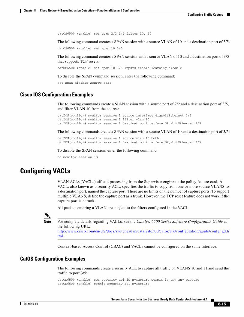
Configuring VACLsVLAN ACLs (VACLs) offload processing from the Supervisor engine to the policy feature card. A VACL, also known as a security ACL, specifies the traffic to copy from one or more source VLANS to a destination port, named the capture port. There are no limits on the number of capture ports. To support multiple VLANS, define the capture port as a trunk. However, the TCP reset feature does not work if the capture port is a trunk.
All packets entering a VLAN are subject to the filters configured in the VACL.
Note For complete details regarding VACLs, see the Catalyst 6500 Series Software Configuration Guide at the following URL: http://www.cisco.com/en/US/docs/switches/lan/catalyst6500/catos/8.x/configuration/guide/confg_gd.html.
Context-based Access Control (CBAC) and VACLs cannot be configured on the same interface.
CatOS Configuration Examples
The following commands create a security ACL to capture all traffic on VLANS 10 and 11 and send the traffic to port 3/5:
catOS6500 (enable) set security acl ip MyCapture permit ip any any capturecatOS6500 (enable) commit security acl MyCapture
8-15Server Farm Security in the Business Ready Data Center Architecture v2.1
OL-9015-01

Chapter 8 Cisco Network-Based Intrusion Detection—Functionalities and Configuration Configuring Traffic Capture
catOS6500 (enable) set security acl map MyCapture 10,11catOS6500 (enable) set security acl capture-ports 3/5
To remove the VACL capture, use the clear security acl MyCapture command. To commit the changes, use the commit security acl MyCapture command.
Cisco IOS Configuration Examples
The following commands create a security ACL to capture all traffic on VLANS 100 and 101 that are not related to SSL (port 443):
catIOS(config)# access-list 100 permit ip any anycatIOS(config)# access-list 101 deny ip any any eq 443catIOS(config)# vlan access-map MyCap 10catIOS(config-access-map)# match ip address 200catIOS(config-access-map)# action forward capturecatIOS(config)# vlan access-map MyCap 20catIOS(config-access-map)# match ip address 201catIOS(config-access-map)# action forwardcatIOS(config)# vlan filter MyCap vlan-list 100 , 101catIOS(config)# interface gi3/5catIOS(config-if)# switchport capture
Use the no form of the previous commands to remove the VACL configuration in Cisco IOS.
Configuring RSPAN with VACLRSPAN allows monitoring network traffic across switches. RSPAN supports source ports or source VLANs and destination ports on different switches. Applying VACLs to the destination (RSPAN) VLAN lets you filter captured traffic destined for the sensor. See Chapter 7, “Traffic Capturing for Granular Traffic Analysis,” for additional details.
CatOS Configuration Example
The following commands create the RSPAN session to send all 200 and 201 VLAN traffic to destination port 3/1:
catOS6500 (enable) set vlan 100 rspan name IDS_CAPTURE state activecatOS6500 (enable) set security acl ip MyACL permit ip any anycatOS6500 (enable) commit security acl MyACLcatOS6500 (enable) set security acl map MyACL 100catOS6500 (enable) set rspan source 200,201 100 both multicast enable createcatOS6500 (enable) set rspan destination 3/1 100 create
Cisco IOS Configuration Example
The following commands create the RSPAN session and send all non-SSL VLAN 20 traffic to the RSPAN VLAN 100:
catIOS(config)# vlan access-map RSPAN-VACL 10catIOS(config-access-map)# action forwardcatIOS(config-access-map)# match ip address IDS-TRAFFICcatIOS(config-access-map)# vlan filter RSPAN-VACL vlan-list 100catIOS(config)# interface vlan100catIOS(config-if)# description RSPAN Destination VLANcatIOS(config-if)# no ip addresscatIOS(config-if)# ip access-list extended IDS-TRAFFIC
8-16Server Farm Security in the Business Ready Data Center Architecture v2.1
OL-9015-01

Chapter 8 Cisco Network-Based Intrusion Detection—Functionalities and Configuration Small-to-Medium Management Tools
catIOS(config-ext-nacl)# deny tcp any any eq 443catIOS(config-ext-nacl)# deny tcp any eq 443 anycatIOS(config-ext-nacl)# permit ip any anycatIOS(config)# monitor session 1 source vlan 20 rxcatIOS(config)# monitor session 1 destination remote vlan 100 reflector-port fa0/24
Use the no form of the previous commands to remove the RSPAN configuration in Cisco IOS.
Configuring MLS IP IDSVACL capture does not work in conjunction with CBAC on a network segment. To provide similar capabilities with Cisco IOS, enter the mls ip ids command on the VLAN interface. Configuring the destination port as a trunk permits the capture of multiple VLANs.
CatOS Hybrid Configuration Example
The following commands capture all IP traffic on VLANs 200 and 201 and send to the destination port 3/1:
catHybrid-msfc(config)# ip access-list extended IDS-CapturecatHybrid-msfc(config-ext-nacl)# permit ip any anycatHybrid-msfc(config-ext-nacl)# exitcatHybrid-msfc(config)# int vlan 200catHybrid-msfc(config-if)# mls ip ids IDS-CapturecatHybrid-msfc(config)# int vlan 201catHybrid-msfc(config-if)# mls ip ids IDS-Capture
catHybrid (enable) set security acl capture-ports 3/1
Cisco IOS Configuration Example
The following commands capture all IP traffic on VLANs 200 and 201 and send to the destination port 3/1:
catIOS(config)# ip access-list extended IDS-CapturecatIOS(config-ext-nacl)# permit ip any anycatIOS(config-ext-nacl)# exitcatIOS(config)# int vlan 200catIOS(config-if)# mls ip ids IDS-CapturecatIOS(config)# int vlan 201catIOS(config-if)# mls ip ids IDS-CapturecatIOS(config-if)# int gig3/1catIOS(config-if)# switchport capture
Small-to-Medium Management ToolsThis section describes management tools that are suitable for use in small-to-medium-sized networks. It includes the following topics:
• Using IDS Device Manager
• Using IDS Event Viewer
8-17Server Farm Security in the Business Ready Data Center Architecture v2.1
OL-9015-01

Chapter 8 Cisco Network-Based Intrusion Detection—Functionalities and Configuration Small-to-Medium Management Tools
To monitor and maintain Cisco IDS sensors, Cisco provides a range of management tools designed for the small business to the large enterprise. Scalability should be your first consideration when choosing a management solution for Cisco IDS and you should have some idea about the maximum number of sensors your network requires. Whatever management solution you select must scale sufficiently and provide the following services:
• Sensor configuration
• Alert handling
• Reporting and analysis
Using IDS Device ManagerThe Cisco IDS Device Manager (IDM) is a web-based Java application designed to manage a single network sensor (see Figure 8-5). The IDM is located on the device and is accessible using Netscape or Internet Explorer web browsers. The SSL protocol provides a secure, encrypted session between the web client and sensor.
Figure 8-5 Cisco IDS Device Manager
The primary task of the IDM is to configure a single network sensor. The IDM does not have the capability to distribute configuration modifications to multiple sensors. The administrator must apply security policy modifications one device at a time. However, the IDM utility can configure the automation of signature updates and service pack updates. Signatures, fragmentation reassembly options, and filters are all manageable using this application.
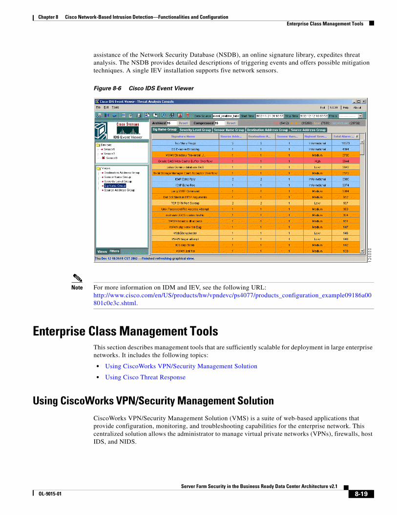
Using IDS Event Viewer The Cisco IDS Event Viewer (IEV) is a web-based Java application designed to manage, analyze, and report alarm events. (See Figure 8-6.) IEV uses a MySQL database to store alarm information and provides real-time monitoring and analysis of archived alarm data. Investigating alarm events with the
8-18Server Farm Security in the Business Ready Data Center Architecture v2.1
OL-9015-01
Chapter 8 Cisco Network-Based Intrusion Detection—Functionalities and Configuration Enterprise Class Management Tools
assistance of the Network Security Database (NSDB), an online signature library, expedites threat analysis. The NSDB provides detailed descriptions of triggering events and offers possible mitigation techniques. A single IEV installation supports five network sensors.
Figure 8-6 Cisco IDS Event Viewer
Note For more information on IDM and IEV, see the following URL: http://www.cisco.com/en/US/products/hw/vpndevc/ps4077/products_configuration_example09186a00801c0e3c.shtml.
Enterprise Class Management ToolsThis section describes management tools that are sufficiently scalable for deployment in large enterprise networks. It includes the following topics:
• Using CiscoWorks VPN/Security Management Solution
• Using Cisco Threat Response
Using CiscoWorks VPN/Security Management Solution CiscoWorks VPN/Security Management Solution (VMS) is a suite of web-based applications that provide configuration, monitoring, and troubleshooting capabilities for the enterprise network. This centralized solution allows the administrator to manage virtual private networks (VPNs), firewalls, host IDS, and NIDS.
8-19Server Farm Security in the Business Ready Data Center Architecture v2.1
OL-9015-01

Chapter 8 Cisco Network-Based Intrusion Detection—Functionalities and Configuration Enterprise Class Management Tools
The VMS IDS Management Center is the application responsible for Cisco IDS configuration. (See Figure 8-7.) It permits publishing security policies remotely to all sensors on the network. The Management Center can support hundreds of sensors. To ease security deployments, the administrator may categorize network sensors into groups. Signature tuning and research through the NSDB are also available with this solution.
Figure 8-7 VMS IDS Management Center
The VMS IDS Monitor Center provides real time event viewing, analysis, and reporting. (See Figure 8-8.) The Monitoring Center provides a complete view of malicious activity on the network across security devices. Customized rules for event correlation and notification options are also available. The event correlation feature allows you to identify threatening traffic patterns through the Monitor Center utility.
8-20Server Farm Security in the Business Ready Data Center Architecture v2.1
OL-9015-01

Chapter 8 Cisco Network-Based Intrusion Detection—Functionalities and Configuration Enterprise Class Management Tools
Figure 8-8 VMS IDS Monitor Center Screen Shot
Using Cisco Threat Response Cisco Threat Response (CTR) is an application built to monitor Cisco NIDS alarms and to perform investigations based on those alarms. These investigations reduce the number of false positives and escalate the importance of real network attacks. CTR is an effective intrusion management solution. The application analyzes network sensor data to initiate in-depth investigations on the targeted host system. By focusing on the target, CTR determines the level of threat that a particular attack poses to a particular system and determines whether the system is compromised. CTR uses the following analysis methods:
• Target operating system or device vulnerability
• Patch-level check
• Detailed system investigation
• Forensic evidence retrieval
• Attack notification
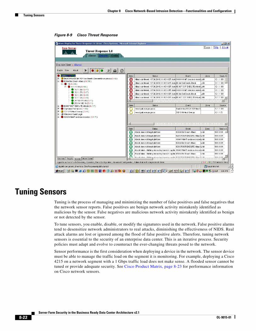
CTR takes advantage of the client/server model for deployment. The CTR server manages alarm data and performs investigations. The CTR client provides a GUI interface for configuring the CTR server and for viewing alarm information. (See Figure 8-9). CTR does not require the installation of client agents on each network host, but the CTR server must have read access to all systems monitored.
8-21Server Farm Security in the Business Ready Data Center Architecture v2.1
OL-9015-01
Chapter 8 Cisco Network-Based Intrusion Detection—Functionalities and Configuration Tuning Sensors
Figure 8-9 Cisco Threat Response
Tuning SensorsTuning is the process of managing and minimizing the number of false positives and false negatives that the network sensor reports. False positives are benign network activity mistakenly identified as malicious by the sensor. False negatives are malicious network activity mistakenly identified as benign or not detected by the sensor.
To tune sensors, you enable, disable, or modify the signatures used in the network. False positive alarms tend to desensitize network administrators to real attacks, diminishing the effectiveness of NIDS. Real attack alarms are lost or ignored among the flood of false positive alerts. Therefore, tuning network sensors is essential to the security of an enterprise data center. This is an iterative process. Security policies must adapt and evolve to counteract the ever-changing threats posed to the network.
Sensor performance is the first consideration when deploying a device in the network. The sensor device must be able to manage the traffic load on the segment it is monitoring. For example, deploying a Cisco 4215 on a network segment with a 1 Gbps traffic load does not make sense. A flooded sensor cannot be tuned or provide adequate security. See Cisco Product Matrix, page 8-23 for performance information on Cisco network sensors.
8-22Server Farm Security in the Business Ready Data Center Architecture v2.1
OL-9015-01
Chapter 8 Cisco Network-Based Intrusion Detection—Functionalities and Configuration Cisco Product Matrix
To maximize the performance of your network sensors, complete the following steps:
Step 1 Establish the starting configuration.
This is usually the default configuration of the network sensor. It is a starting point for the tuning process. Sensors located on similar network segments should employ the same signatures.
Step 2 Monitor the sensor.
Scrutinize alarms to disable signatures created by normal network traffic or that you are certain are not malicious attacks. This reduces the number of false positives.
Step 3 Analyze and tune.
Perform this step in conjunction with Step 2. Monitor and investigate alarms on the system to reduce the number of false positives. A management tool such as CTR can expedite this process. Determine the source (server, network device) of the alarms and whether it is normal behavior for that device or application. Tune signatures where appropriate.
Step 4 Configure response actions.
Enable the advanced features of network sensors, such as TCP resets, shunning, and IP logging.
Step 5 Update sensor signatures.
Apply Cisco signature updates on a regular basis to identify the latest network threat. Monitor the activity generated by the new signatures and repeat the process of tuning. Applying updates regularly reduces the time necessary to tweak a signature.
The process of security is cyclical. Network security policies evolve and mature, and so the devices employed to support it must as well.
Cisco Product MatrixCisco intrusion detection solutions provide flexible deployment options for protecting both enterprise and smaller networks. Intrusion detection services are available in the following sensor types:
• Cisco PIX Firewall
• Cisco IOS routers
• Cisco Intrusion Detection System 4200 Security Appliance (Cisco IDS)
• Cisco Intrusion Detection System Module for the Catalyst 6500 series of switches (Cisco IDSM and IDSM-2)
• Cisco Intrusion Detection System Module for the 2600/3600/3700 series of routers (NM-CIDS)
Choose the best solution for your network environment. Cisco IDS, Cisco IDSM, and Cisco NM-CIDS all use Cisco IDS software. Cisco IDS software runs on a heavily modified version of Red Hat Linux that has been hardened to protect it from attacks. Therefore, use performance to differentiate among the deployment options.
The Cisco PIX Firewall and Cisco IOS router products integrate a subset of intrusion detection services into their operating systems. The Cisco PIX Firewall, for example, currently supports 59 signatures. These devices provide an inline option for intrusion detection services. Branch offices, remote offices, and telecommuters can use the sensor features of these devices.
8-23Server Farm Security in the Business Ready Data Center Architecture v2.1
OL-9015-01

Chapter 8 Cisco Network-Based Intrusion Detection—Functionalities and Configuration Cisco Product Matrix
The NM-CIDS network module provides intrusion detection services integrated into the router. The module uses the same IDS software (version 4.1) that is implemented in the switch and security appliance. The NM-CIDS sensor resides in a single network module slot on the Cisco 2600XM Series, Cisco 3660 Series, and Cisco 3700 Series platforms. This allows the sensor to monitor all of the router interfaces up to 45 Mbps. Branch office environments are a logical deployment scenario for NM-CIDS sensors to protect the corporate network. You can manage the NM-CIDS sensors using Cisco VMS or the embedded IDM/IEV utilities.
Cisco IDS network sensors are dedicated appliances that provide a high level of performance and deployment flexibility. These sensors passively monitor the network through promiscuous ports. The performance capabilities of these devices suit them to the enterprise data center environment. See Table 8-1 for the Cisco IDS appliance models and performance numbers.
The Cisco 4250 XL takes advantage of the Intel IXP 1200 card architecture. This card can support more than three million Ethernet packets per second. The 4250XL has a Gigabit Ethernet interface for monitoring the network.
Cisco IDSM and IDSM-2 are dedicated intrusion detection devices deployed within a Catalyst 6000 chassis. The IDSM-2 supports 600 Mbps of traffic and the Catalyst chassis can house a maximum of eight modules. VMS is the recommended method of management, but the IDS software also supports IDM and IEV. This integrated and scalable intrusion detection solution works well in the enterprise data center.
Note For more deployment details, see Integrating the Intrusion Detection System Module in the Data Center at the following URL: http://www.cisco.com/en/US/solutions/ns340/ns517/ns224/ns304/net_design_guidance0900aecd8010e791.pdf.
Table 8-1 Network Sensor Performance
Network Sensor Performance Mbps
4210 45
4215 80
4235 250
4250 500
4250 XL 1000
8-24Server Farm Security in the Business Ready Data Center Architecture v2.1
OL-9015-01