cisco mds 9000 family cook book.pdf
DESCRIPTION
good for read cvcvxcvfasdgfgfdsTRANSCRIPT

Corporate HeadquartersCisco Systems, Inc.170 West Tasman DriveSan Jose, CA 95134-1706 USAhttp://www.cisco.comTel: 408 526-4000
800 553-NETS (6387)Fax: 408 526-4100
Cisco MDS 9000 Family Cookbook for SAN-OS 2.xSeth MasonVenkat Kirishnamurthyi
4/25/06

Cisco MDS 9000 Family CookbookCopyright © 2004 Cisco Systems, Inc. All rights reserved.
Comments: [email protected]
CCSP, the Cisco Square Bridge logo, Cisco Unity, Follow Me Browsing, FormShare, and StackWise are trademarks of Cisco Systems, Inc.; Changing the Way We Work, Live, Play, and Learn, and iQuick Study are service marks of Cisco Systems, Inc.; and Aironet, ASIST, BPX, Catalyst, CCDA, CCDP, CCIE, CCIP, CCNA, CCNP, Cisco, the Cisco Certified Internetwork Expert logo, Cisco IOS, Cisco Press, Cisco Systems, Cisco Systems Capital, the Cisco Systems logo, Empowering the Internet Generation, Enterprise/Solver, EtherChannel, EtherFast, EtherSwitch, Fast Step, GigaDrive, GigaStack, HomeLink, Internet Quotient, IOS, IP/TV, iQ Expertise, the iQ logo, iQ Net Readiness Scorecard, LightStream, Linksys, MeetingPlace, MGX, the Networkers logo, Networking Academy, Network Registrar, Packet, PIX, Post-Routing, Pre-Routing, ProConnect, RateMUX, Registrar, ScriptShare, SlideCast, SMARTnet, StrataView Plus, SwitchProbe, TeleRouter, The Fastest Way to Increase Your Internet Quotient, TransPath, and VCO are registered trademarks of Cisco Systems, Inc. and/or its affiliates in the United States and certain other countries.
All other trademarks mentioned in this document or Website are the property of their respective owners. The use of the word partner does not imply a partnership relationship between Cisco and any other company. (0406R)

OL-xxxxx-xx
C O N T E N T S
Preface ix
Audience ix
About the Authors ix
Organization x
Document Conventions x
Related Documentation xi
Obtaining Documentation xii
Cisco.com xii
Product Documentation DVD xiii
Ordering Documentation xiii
Documentation Feedback xiii
Cisco Product Security Overview xiv
Reporting Security Problems in Cisco Products xiv
Obtaining Technical Assistance xv
Cisco Technical Support & Documentation Website xv
Submitting a Service Request xv
Definitions of Service Request Severity xvi
Obtaining Additional Publications and Information xvi
C H A P T E R 1 Managing a Cisco MDS 9000 Switch 1-1
Using SNMP to Monitor the MDS 1-1
Events 1-1
Thresholds 1-2
Third Party Management Application Configuration 1-3
Advanced Cisco MDS Monitoring 1-8
CFS: Cisco Fabric Services 1-8
Fabric Manager and CFS 1-10
How does this work? 1-11
CFS CLI Commands 1-11
Which switches are CFS capable? 1-11
What CFS applications do I have and what is their scope? 1-12
Why am I locked out of an application by CFS? 1-12
Command Scheduler 1-13
Automated Switch Configuration Backup 1-13
iiiCisco MDS 9000 Family Cookbook for SAN-OS 2.x
Contents
Copying Files to and from a Switch 1-16
Copying Files Using the CLI 1-16
Secure Copy Protocol 1-16
Secure File Transfer Protocol 1-17
Managing Files on the Standby Supervisor 1-18
Delete a File from the Standby Supervisor 1-18
Firmware Upgrades and Downgrades 1-20
Upgrading firmware with the CLI 1-20
Downgrading Firmware with the CLI 1-22
Upgrading Firmware with Fabric Manager 1-23
Password Recovery 1-26
Installing a License 1-29
Using the CLI to Install a License: 1-29
Using Fabric Manager to Install a License 1-30
Which Feature is Enabling the License Grace Period? 1-33
Check with Fabric Manager 1-33
Check with the CLI 1-33
Copying Core Files From Switch 1-34
Restoring a Fixed Switch Configuration 1-35
Configuring an NTP Server 1-38
Configuring NTP with CFS 1-38
Configure NTP without CFS 1-39
What to do Before Calling TAC 1-41
Saving the Configuration Across the Fabric 1-43
How to Disable the Web Server 1-44
Device Aliases 1-45
Manipulating Device Aliases with the CLI 1-46
Displaying Device Aliases with the CLI 1-46
Creating Device Aliases with the CLI 1-46
Converting FC Aliases to Device Aliases 1-47
Device Aliases with Fabric Manager 1-48
Enabling Fabric Manager to use Device Aliases 1-49
Creating a Device Alias for an Existing Device 1-50
Creating a Device Alias for a New Device 1-51
Implementing Syslog 1-52
Configuring Call Home 1-54
What are Alert Groups? 1-54
Configure Call Home to Send All Notifications to a Single E-Mail Address 1-55
ivCisco MDS 9000 Family Cookbook for SAN-OS 2.x
OL-xxxxx-xx
Contents
Managing Fabric Manager 1-58
Operating Fabric Manager Through a Firewall using SNMP Proxy 1-58
Configuration using a non-NAT Packet Filter 1-58
Performance Manager (PM) using Fabric Manager Server (FMS) 1-60
Launching Performance Manager Configuration from a Host Running FMS 1-60
C H A P T E R 2 Account Management 2-1
Creating User Accounts 2-2
Creating a User Role 2-3
Creating a Role with Device Manager 2-4
Creating a Role with CLI 2-7
Configuring TACACS+ with Cisco SecureACS 2-9
Authentication and Authorization with TACACS+ 2-9
Configure SecureACS Server 2-10
Configure TACACS+ on the MDS Switch 2-14
Accounting with TACACS+ 2-15
Configuring the MDS Switch 2-16
Configuring SecureACS 2-16
Providing Password-free Access Using SSH 2-19
C H A P T E R 3 Physical Interfaces 3-1
Configuring FC ports 3-1
Port Description 3-1
Port Speed 3-1
Port Mode Auto 3-2
Port Mode E 3-2
Port Mode F 3-2
Port Mode FL 3-2
Port Mode Fx 3-3
Port Mode SD 3-3
Port mode ST 3-3
Port mode TL 3-3
Configuring Trunking E ports 3-4
Trunk Port Mode 3-4
Configuring Trunk Ports to Filter Specific VSANs 3-4
Enabling Port Beaconing 3-4
Configuring Gigabit Ethernet Ports 3-5
Configuring VRRP 3-5
Implementing WWN Based VSANs (DPVM) 3-7
vCisco MDS 9000 Family Cookbook for SAN-OS 2.x
OL-xxxxx-xx
Contents
Adding Existing Devices to DPVM 3-9
Adding New Devices to DPVM 3-11
Modify the VSAN Assignment of a DPVM Entry 3-13
DPVM Conflicting Entries 3-14
DPVM with the CLI 3-16
Adding Existing Devices to DPVM 3-16
Adding New Devices to DPVM 3-17
Modify the VSAN Assignment of a DPVM Entry 3-18
C H A P T E R 4 Logical Interfaces 4-1
Port Channels 4-1
Quiesce a Port Channel or ISL Link 4-1
Creating a Port Channel using FM 4-2
Creating a Port Channel using CLI 4-5
Adding a New Member to a Port Channel (FM) 4-7
Adding New Members to a Port Channel (CLI) 4-9
Modifying the VSAN Allowed List on a Port Channel (FM) 4-10
Modifying the VSAN Allowed List on a port channel (CLI) 4-10
C H A P T E R 5 VSANs 5-1
Creating a VSAN and Adding Interfaces 5-1
Modifying VSAN Attributes with Fabric Manager 5-3
Converting an Existing VSAN DomainID and Enabling FCID with Fabric Manager 5-4
Modifying VSAN Attributes with the CLI 5-7
Creating a VSAN on a single switch and adding an Interface 5-7
Setting VSAN Interop Mode 5-7
Interop Mode 1 5-8
Interop Mode 2 5-8
Interop Mode 3 5-8
Changing the Load-balancing Scheme 5-8
Sequence Level load-balancing (Source_ID, Destination_ID) 5-8
Exchange level load balancing (S_ID, D_ID, OX_ID) 5-9
Converting an Existing VSAN to Static DomainID and Enabling Persistent FCID using CLI 5-9
Restarting a VSAN 5-10
Assigning a Predetermined FCID to a PWWN 5-10
C H A P T E R 6 Zoning 6-1
Enhanced Zoning 6-1
Enabling Enhanced Zoning 6-2
viCisco MDS 9000 Family Cookbook for SAN-OS 2.x
OL-xxxxx-xx

Contents
Enabling Enhanced Zoning with the CLI 6-3
Enabling Enhanced Zoning with Fabric Manager 6-3
Displaying User with Current Lock in CLI and Fabric Manager 6-4
Zone Sets 6-6
Distributing Zone Sets 6-6
Distributing Zone Sets Automatically 6-6
Distributing Zone Sets Manually 6-7
Zones 6-8
Creating a Zone and Adding it to a Zone Set with Fabric Manager 6-8
Creating Non-pWWN Based Zones 6-13
Creating a Zone and Adding it to a Zone Set with the CLI Standalone Method 6-14
Creating a Zone and Adding it to a Zone Set with the CLI Inline Method 6-15
Creating a FC Alias-based Zone with the CLI 6-16
Creating an Interface-based Zone with the CLI 6-18
C H A P T E R 7 Inter-VSAN Routing 7-1
IVR Core Components 7-2
IVR Topology 7-2
Auto-Topology 7-2
Transit VSANs 7-3
Configuring a Three Switch, Two Transit VSAN Topology with CFS 7-4
IVR Zones and Zone Sets 7-7
IVR with CFS 7-8
IVR-1 7-10
Enabling IVR-1 7-10
Enabling IVR-1 with the CLI 7-10
Enabling IVR-1 with Fabric Manager 7-11
Configuring a Single Switch and Two VSANs 7-12
Creating the IVR Topology 7-12
Creating the IVR Zone Set and Zones 7-13
IVR-2 with FC-NAT 7-16
Enabling IVR-2 7-16
Upgrading from IVR-1 to IVR-2 7-19
Configuring Persistent FC IDs in IVR 7-21
Configuring a Single Switch with Two VSANs 7-23
Adding a New IVR Enabled Switch 7-27
C H A P T E R 8 FCIP 8-1
Enabling FCIP 8-1
viiCisco MDS 9000 Family Cookbook for SAN-OS 2.x
OL-xxxxx-xx

Contents
Configuring FCIP on a Switch with CLI 8-2
Configuring Multiple FCIP Tunnels Using a Single gigE port 8-7
Configuring FCIP with IPsec using FM 8-15
Tuning FCIP 8-24
TCP Tuning: Latency and Available Bandwidth 8-24
Enabling FCIP Write Acceleration 8-25
Enabling FCIP Compression 8-26
Enabling Tape Acceleration 8-27
Enabling Tape Acceleration from the CLI 8-27
Enabling Tape Acceleration from the CLI 8-30
Testing and Tuning the FCIP link with SET 8-31
C H A P T E R 9 iSCSI 9-1
Enabling iSCSI 9-1
Configuring iSCSI on an MDS Switch in Transparent Mode 9-2
Configuring iSCSI on the MDS Switch in Proxy initiator mode 9-7
Configuring iSCSI Client Initiators on Hosts 9-12
Configuring iSCSI on Microsoft Windows 9-12
Configuring an iSCSI Client on Linux 9-16
viiiCisco MDS 9000 Family Cookbook for SAN-OS 2.x
OL-xxxxx-xx

Preface
This document adresses the configuration and implementation of fabrics using Cisco’s MDS 9000 Family of Fibre Channel Switch and Director Class products. The configuration procedures and components provided have been tested and validated by Cisco’s Solution-Interoperability Engineering department.
This cookbook provides simplified, concise recipes (procedures) for tasks that might be required to configure a Cisco MDS 9000 switch. This guide does not replace the MDS 9000 Family Configuration Guides.
AudienceThis document is designed for use by Cisco TAC, Sales, Support Engineers, Professional Service Partners, Systems Administrators and others responsible for the design and deployment of Storage Area Networks in the data center environment.
This is field-driven book, meaning that the intended audience (the storage administrators, technical support engineers, SEs and CEs) is also the source of information for these procedures. Their requirements for a procedure are what determine the content.
If there are procedures that you feel should be covered in this book, or if you have any other comments or questions, please notify us via email at: [email protected]. Please state the document name, page number, and details of the request.
About the AuthorsSeth Mason is a Network Consulting Engineer with the DCN team at Cisco Systems. His areas of expertise are SAN migration, Disaster Recovery, interoperability and InterVSAN Routing. He graduated from Auburn University in 1998 with a Bachelor of Computer Engineering and has focused on SANs ever since, including Product Engineer with IBM’s Storage Subsystems Group, Silicon Valley Operations team lead with StorageNetworks and NCE with Andiamo Systems. Seth has continued to further his expertise in storage by authoring both the MDS-9000 Family Cookbook for SAN-OS 1.x and MDS-9000 Family Cookbook for SAN-OS 2.x as well as the MDS-9000 Switch to Switch Interoperability Configuration Guide, and is a member of the team that authored the CCIE exam in Storage Networking.
ixCisco MDS 9000 Family Cookbook for SAN-OS 2.x
OL-xxxxx-xx

PrefaceOrganization
Venkat Kirishnamurthyi is a Network Consulting Engineer with the DCN team at Cisco Systems. His areas of expertise are SAN design, migration, and storage replication for disaster recovery. He graduated from Bangalore University in 1992 with a Bachelor of Electronics and Communications Engineering. Since then he has worked as a Systems Administrator at Hughes Software Systems India and as a Sr. Systems Administrator and Sr. Storage Administrator at Cisco Systems. Venkat has continued his storage expertise by authoring SAN migration guides for HPUX and Solaris hosts, both the MDS-9000 Family Cookbook for SAN-OS 1.x and MDS-9000 Family Cookbook for SAN-OS 2.x. He is a member of the team that authored the CCIE exam for Storage Networking.
OrganizationThis guide is organized as follows:
Document ConventionsCommand descriptions use these conventions:
Chapter Title Content Description
Chapter 1 Managing a Cisco MDS 9000 Switch Recipes for various aspects of managing the Cisco MDS 9000 switches.
Chapter 2 Account Management Procedures for managing users and their accounts.
Chapter 3 Physical Interfaces Procedures for configuring the various FibreChannel (FC) and Gigabit Ethernet ports on Cisco MDS 9000 switches.
Chapter 4 Logical Interfaces Procedures for building, modifying and reducing a PortChannel.
Chapter 5 VSANs Procedures for creating and configuring VSANs.
Chapter 6 Zoning Procedures for creating and configuring zones and zone sets.
Chapter 7 Inter-VSAN Routing Procedures for configuring inter-VSAN routing.
Chapter 8 FCIP Procedures for creating and managing FCIP links between Cisco MDS 9000 switches.
Chapter 9 iSCSI Procedures for configuring iSCSI on Cisco MDS 9000 switches.
boldface font Commands and keywords are in boldface.
italic font Arguments for which you supply values are in italics.
[ ] Elements in square brackets are optional.
[ x | y | z ] Optional alternative keywords are grouped in brackets and separated by vertical bars.
xCisco MDS 9000 Family Cookbook for SAN-OS 2.x
OL-xxxxx-xx
PrefaceRelated Documentation
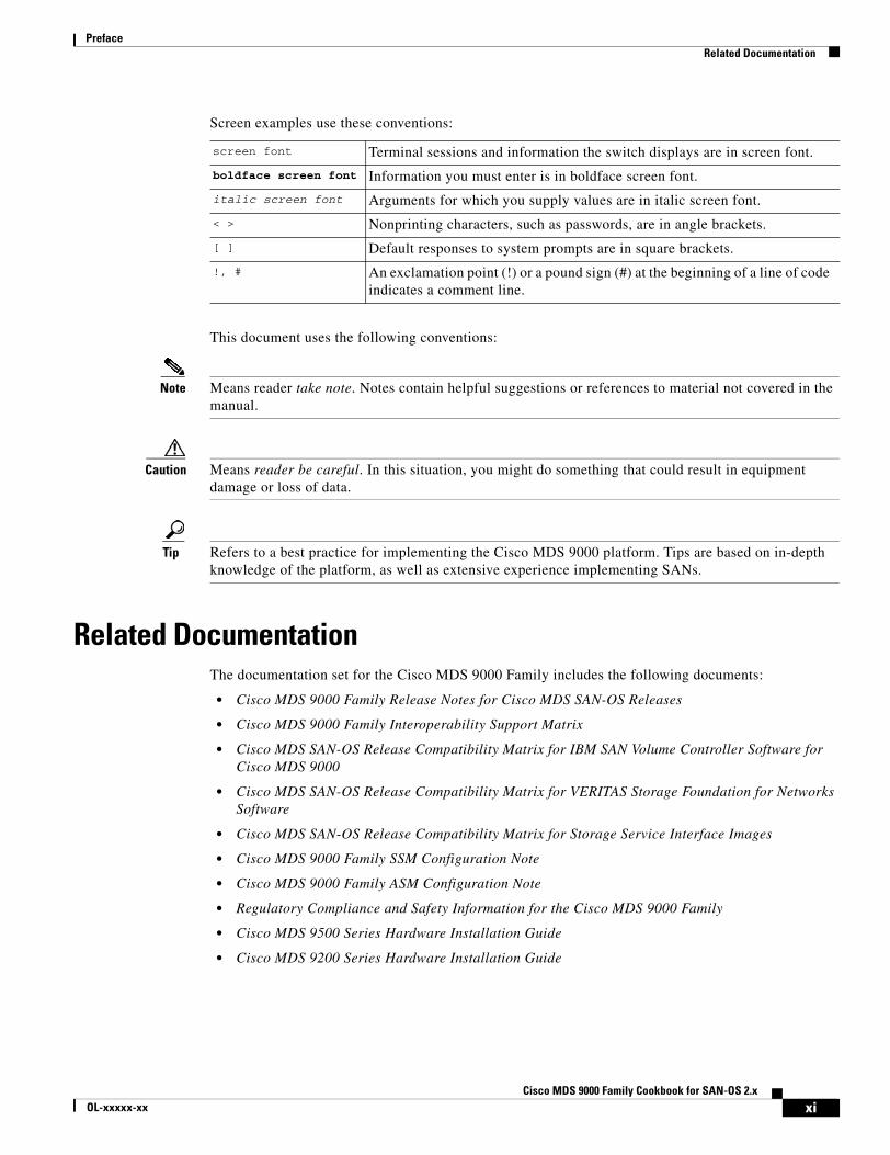
Screen examples use these conventions:
This document uses the following conventions:
Note Means reader take note. Notes contain helpful suggestions or references to material not covered in the manual.
Caution Means reader be careful. In this situation, you might do something that could result in equipment damage or loss of data.
Tip Refers to a best practice for implementing the Cisco MDS 9000 platform. Tips are based on in-depth knowledge of the platform, as well as extensive experience implementing SANs.
Related DocumentationThe documentation set for the Cisco MDS 9000 Family includes the following documents:
• Cisco MDS 9000 Family Release Notes for Cisco MDS SAN-OS Releases
• Cisco MDS 9000 Family Interoperability Support Matrix
• Cisco MDS SAN-OS Release Compatibility Matrix for IBM SAN Volume Controller Software for Cisco MDS 9000
• Cisco MDS SAN-OS Release Compatibility Matrix for VERITAS Storage Foundation for Networks Software
• Cisco MDS SAN-OS Release Compatibility Matrix for Storage Service Interface Images
• Cisco MDS 9000 Family SSM Configuration Note
• Cisco MDS 9000 Family ASM Configuration Note
• Regulatory Compliance and Safety Information for the Cisco MDS 9000 Family
• Cisco MDS 9500 Series Hardware Installation Guide
• Cisco MDS 9200 Series Hardware Installation Guide
screen font Terminal sessions and information the switch displays are in screen font.
boldface screen font Information you must enter is in boldface screen font.
italic screen font Arguments for which you supply values are in italic screen font.
< > Nonprinting characters, such as passwords, are in angle brackets.
[ ] Default responses to system prompts are in square brackets.
!, # An exclamation point (!) or a pound sign (#) at the beginning of a line of code indicates a comment line.
xiCisco MDS 9000 Family Cookbook for SAN-OS 2.x
OL-xxxxx-xx

PrefaceObtaining Documentation
• Cisco MDS 9216 Switch Hardware Installation Guide
• Cisco MDS 9100 Series Hardware Installation Guide
• Cisco MDS 9020 Fabric Switch Hardware Installation Guide
• Cisco MDS 9000 Family Software Upgrade and Downgrade Guide
• Cisco MDS 9000 Family Configuration Guide
• Cisco MDS 9000 Family Command Reference
• Cisco MDS 9020 Fabric Switch Configuration Guide and Command Reference
• Cisco MDS 9000 Family Fabric Manager Configuration Guide
• Cisco MDS 9000 Family Fabric and Device Manager Online Help
• Cisco MDS 9000 Family SAN Volume Controller Configuration Guide
• Cisco MDS 9000 Family Quick Configuration Guide
• Cisco MDS 9000 Family Fabric Manager Quick Configuration Guide
• Cisco MDS 9000 Family MIB Quick Reference
• Cisco MDS 9020 Fabric Switch MIB Quick Reference
• Cisco MDS 9000 Family CIM Programming Reference
• Cisco MDS 9000 Family System Messages Reference
• Cisco MDS 9020 Fabric Switch System Messages Reference
• Cisco MDS 9000 Family Troubleshooting Guide
• Cisco MDS 9000 Family Port Analyzer Adapter 2 Installation and Configuration Note
• Cisco MDS 9000 Family Port Analyzer Adapter Installation and Configuration Note
For information on VERITAS Storage Foundation™ for Networks for the Cisco MDS 9000 Family, refer to the VERITAS website: http://support.veritas.com/
For information on IBM TotalStorage SAN Volume Controller Storage Software for the Cisco MDS 9000 Family, refer to the IBM TotalStorage Support website: http://www.ibm.com/storage/support/2062-2300/
Obtaining DocumentationCisco documentation and additional literature are available on Cisco.com. You can also obtain technical assistance and other technical resources from Cisco Systems, as described below.
Cisco.comAccess the most current Cisco documentation at:
http://www.cisco.com/techsupport
Access the Cisco website at:
http://www.cisco.com
Access international Cisco websites at:
http://www.cisco.com/public/countries_languages.shtml
xiiCisco MDS 9000 Family Cookbook for SAN-OS 2.x
OL-xxxxx-xx

PrefaceDocumentation Feedback
Product Documentation DVDCisco documentation and other literature is available in the Product Documentation DVD package, which may have shipped with your product. The Product Documentation DVD is updated regularly and may be more current than printed documentation.
The Product Documentation DVD is a comprehensive library of technical product documentation on portable media. The DVD enables you to access multiple versions of hardware and software installation, configuration, and command guides for Cisco products and to view technical documentation in HTML. With the DVD, you have access to the same documentation that is found on the Cisco website without being connected to the Internet. Certain products also have .pdf versions of the documents.
The Product Documentation DVD is available as a single unit or as a subscription. Registered Cisco.com users (Cisco direct customers) can order a Product Documentation DVD (product number DOC-DOCDVD=) from the Ordering tool or Cisco Marketplace.
Cisco Ordering tool:
http://www.cisco.com/en/US/partner/ordering/
Cisco Marketplace:
http://www.cisco.com/go/marketplace/
Ordering DocumentationBeginning June 30, 2005, registered Cisco.com users may order Cisco documentation at the Product Documentation Store in the Cisco Marketplace at this URL:
http://www.cisco.com/go/marketplace/
Cisco will continue to support documentation orders using the ordering tool:
• Registered Cisco.com users (Cisco direct customers) can order documentation from the Ordering tool:
http://www.cisco.com/en/US/partner/ordering/
• Instructions for ordering documentation using the Ordering tool are at this URL:
http://www.cisco.com/univercd/cc/td/doc/es_inpck/pdi.htm
• Nonregistered Cisco.com users can order documentation through a local account representative by calling Cisco Systems Corporate Headquarters (California, USA) at 408 526-7208 or, elsewhere in North America, by calling 1 800 553-NETS (6387).
Documentation FeedbackYou can rate and provide feedback about Cisco technical documents by completing the online feedback form that appears with the technical documents on Cisco.com.
You can send comments about Cisco documentation to [email protected].
xiiiCisco MDS 9000 Family Cookbook for SAN-OS 2.x
OL-xxxxx-xx

PrefaceCisco Product Security Overview
You can submit comments by using the response card (if present) behind the front cover of your document or by writing to the following address:
Cisco SystemsAttn: Customer Document Ordering170 West Tasman DriveSan Jose, CA 95134-9883
We appreciate your comments.
Cisco Product Security OverviewCisco provides a free online Security Vulnerability Policy portal at this URL:
http://www.cisco.com/en/US/products/products_security_vulnerability_policy.html
From this site, you can:
• Report security vulnerabilities in Cisco products.
• Obtain assistance with security incidents that involve Cisco products.
• Register to receive security information from Cisco.
A current list of security advisories and notices for Cisco products is available at this URL:
http://www.cisco.com/go/psirt
If you prefer to see advisories and notices as they are updated in real time, you can access a Product Security Incident Response Team Really Simple Syndication (PSIRT RSS) feed from this URL:
http://www.cisco.com/en/US/products/products_psirt_rss_feed.html
Reporting Security Problems in Cisco ProductsCisco is committed to delivering secure products. We test our products internally before we release them, and we strive to correct all vulnerabilities quickly. If you think that you might have identified a vulnerability in a Cisco product, contact PSIRT:
• Emergencies— [email protected]
An emergency is either a condition in which a system is under active attack or a condition for which a severe and urgent security vulnerability should be reported. All other conditions are considered nonemergencies.
• Nonemergencies— [email protected]
In an emergency, you can also reach PSIRT by telephone:
• 1 877 228-7302
• 1 408 525-6532
Tip We encourage you to use Pretty Good Privacy (PGP) or a compatible product to encrypt any sensitive information that you send to Cisco. PSIRT can work from encrypted information that is compatible with PGP versions 2.x through 8.x.
xivCisco MDS 9000 Family Cookbook for SAN-OS 2.x
OL-xxxxx-xx

PrefaceObtaining Technical Assistance
Never use a revoked or an expired encryption key. The correct public key to use in your correspondence with PSIRT is the one linked in the Contact Summary section of the Security Vulnerability Policy page at this URL:
http://www.cisco.com/en/US/products/products_security_vulnerability_policy.html
The link on this page has the current PGP key ID in use.
Obtaining Technical AssistanceCisco Technical Support provides 24-hour-a-day award-winning technical assistance. The Cisco Technical Support & Documentation website on Cisco.com features extensive online support resources. In addition, if you have a valid Cisco service contract, Cisco Technical Assistance Center (TAC) engineers provide telephone support. If you do not have a valid Cisco service contract, contact your reseller.
Cisco Technical Support & Documentation WebsiteThe Cisco Technical Support & Documentation website provides online documents and tools for troubleshooting and resolving technical issues with Cisco products and technologies. The website is available 24 hours a day, at this URL:
http://www.cisco.com/techsupport
Access to all tools on the Cisco Technical Support & Documentation website requires a Cisco.com user ID and password. If you have a valid service contract but do not have a user ID or password, you can register at this URL:
http://tools.cisco.com/RPF/register/register.do
Note Use the Cisco Product Identification (CPI) tool to locate your product serial number before submitting a web or phone request for service. You can access the CPI tool from the Cisco Technical Support & Documentation website by clicking the Tools & Resources link under Documentation & Tools. Choose Cisco Product Identification Tool from the Alphabetical Index drop-down list, or click the Cisco Product Identification Tool link under Alerts & RMAs. The CPI tool offers three search options: by product ID or model name; by tree view; or for certain products, by copying and pasting show command output. Search results show an illustration of your product with the serial number label location highlighted. Locate the serial number label on your product and record the information before placing a service call.
Submitting a Service RequestUsing the online TAC Service Request Tool is the fastest way to open S3 and S4 service requests. (S3 and S4 service requests are those in which your network is minimally impaired or for which you require product information.) After you describe your situation, the TAC Service Request Tool provides recommended solutions. If your issue is not resolved using the recommended resources, your service request is assigned to a Cisco engineer. The TAC Service Request Tool is located at this URL:
http://www.cisco.com/techsupport/servicerequest
xvCisco MDS 9000 Family Cookbook for SAN-OS 2.x
OL-xxxxx-xx

PrefaceObtaining Additional Publications and Information
For S1 or S2 service requests or if you do not have Internet access, contact the Cisco TAC by telephone. (S1 or S2 service requests are those in which your production network is down or severely degraded.) Cisco engineers are assigned immediately to S1 and S2 service requests to help keep your business operations running smoothly.
To open a service request by telephone, use one of the following numbers:
Asia-Pacific: +61 2 8446 7411 (Australia: 1 800 805 227)EMEA: +32 2 704 55 55USA: 1 800 553-2447
For a complete list of Cisco TAC contacts, go to this URL:
http://www.cisco.com/techsupport/contacts
Definitions of Service Request SeverityTo ensure that all service requests are reported in a standard format, Cisco has established severity definitions.
Severity 1 (S1)—Your network is “down,” or there is a critical impact to your business operations. You and Cisco will commit all necessary resources around the clock to resolve the situation.
Severity 2 (S2)—Operation of an existing network is severely degraded, or significant aspects of your business operation are negatively affected by inadequate performance of Cisco products. You and Cisco will commit full-time resources during normal business hours to resolve the situation.
Severity 3 (S3)—Operational performance of your network is impaired, but most business operations remain functional. You and Cisco will commit resources during normal business hours to restore service to satisfactory levels.
Severity 4 (S4)—You require information or assistance with Cisco product capabilities, installation, or configuration. There is little or no effect on your business operations.
Obtaining Additional Publications and InformationInformation about Cisco products, technologies, and network solutions is available from various online and printed sources.
• Cisco Marketplace provides a variety of Cisco books, reference guides, documentation, and logo merchandise. Visit Cisco Marketplace, the company store, at this URL:
http://www.cisco.com/go/marketplace/
• Cisco Press publishes a wide range of general networking, training and certification titles. Both new and experienced users will benefit from these publications. For current Cisco Press titles and other information, go to Cisco Press at this URL:
http://www.ciscopress.com
• Packet magazine is the Cisco Systems technical user magazine for maximizing Internet and networking investments. Each quarter, Packet delivers coverage of the latest industry trends, technology breakthroughs, and Cisco products and solutions, as well as network deployment and troubleshooting tips, configuration examples, customer case studies, certification and training information, and links to scores of in-depth online resources. You can access Packet magazine at this URL:
http://www.cisco.com/packet
xviCisco MDS 9000 Family Cookbook for SAN-OS 2.x
OL-xxxxx-xx

PrefaceObtaining Additional Publications and Information
• iQ Magazine is the quarterly publication from Cisco Systems designed to help growing companies learn how they can use technology to increase revenue, streamline their business, and expand services. The publication identifies the challenges facing these companies and the technologies to help solve them, using real-world case studies and business strategies to help readers make sound technology investment decisions. You can access iQ Magazine at this URL:
http://www.cisco.com/go/iqmagazine
or view the digital edition at this URL:
http://ciscoiq.texterity.com/ciscoiq/sample/
• Internet Protocol Journal is a quarterly journal published by Cisco Systems for engineering professionals involved in designing, developing, and operating public and private internets and intranets. You can access the Internet Protocol Journal at this URL:
http://www.cisco.com/ipj
• Networking products offered by Cisco Systems, as well as customer support services, can be obtained at this URL:
http://www.cisco.com/en/US/products/index.html
• Networking Professionals Connection is an interactive website for networking professionals to share questions, suggestions, and information about networking products and technologies with Cisco experts and other networking professionals. Join a discussion at this URL:
http://www.cisco.com/discuss/networking
• World-class networking training is available from Cisco. You can view current offerings at this URL:
http://www.cisco.com/en/US/learning/index.html
xviiCisco MDS 9000 Family Cookbook for SAN-OS 2.x
OL-xxxxx-xx

PrefaceObtaining Additional Publications and Information
xviiiCisco MDS 9000 Family Cookbook for SAN-OS 2.x
OL-xxxxx-xx

Cisco MDS 9078-xxxxx-xx
C H A P T E R 1
Managing a Cisco MDS 9000 SwitchThis chapter provides recipes for managing a Cisco MDS 9000 switch. These non-datapath topics include access control, accounting, event resolution, and monitoring.
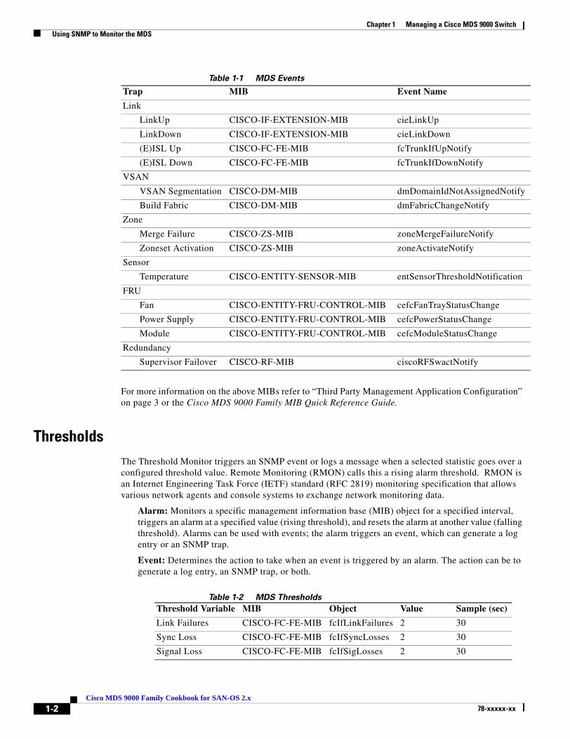
Using SNMP to Monitor the MDSCisco MDS 9000 switches support a large number of MIBs and events to notify administrators. Customers have expressed the need for monitoring solution that does not overwhelm the administrators. To address this need, working with MDS SAN administrators, the below listed events and thresholds are identified as the standard events for an SAN administrator to monitor.
The events listed in Table 1-1 are a subset of the full set of events that the Cisco MDS 9000 switches support. Table 2 lists standard thresholds of interest to monitor. Customers have the flexibility to customize the monitoring solution to meet their specific needs, please refer to the advanced monitoring section at the end of the document.
EventsThe Cisco MDS SAN-OS supports over 100+ MIBs and supports Simple Network Management Protocol (SNMP) versions v1, v2 and v3.
Cisco MDS SAN-OS provides ability to configure traps that are sent out. To enable traps listed in Table 1-1 the following configuration changes are required on the Cisco MDS using 9000 switch via the Command Line Interface (CLI). These changes enable Cisco MDS specific link up and link down traps, entity, fcdomain, and zone traps to be forwarded to the monitoring application using the Cisco MDS CLI commands shown below.
switch(config)# snmp enable traps link cisco //link interface eventsswitch(config)# snmp enable traps entity //enables entity eventsswitch(config)# snmp enable traps fcdomain//fcdomain eventsswitch(config)# snmp enable traps zone//zone events
1-100 Family Cookbook for SAN-OS 2.x
Chapter 1 Managing a Cisco MDS 9000 Switch Using SNMP to Monitor the MDS
Table 1-1 MDS Events
For more information on the above MIBs refer to “Third Party Management Application Configuration” on page 3 or the Cisco MDS 9000 Family MIB Quick Reference Guide.
ThresholdsThe Threshold Monitor triggers an SNMP event or logs a message when a selected statistic goes over a configured threshold value. Remote Monitoring (RMON) calls this a rising alarm threshold. RMON is an Internet Engineering Task Force (IETF) standard (RFC 2819) monitoring specification that allows various network agents and console systems to exchange network monitoring data.
Alarm: Monitors a specific management information base (MIB) object for a specified interval, triggers an alarm at a specified value (rising threshold), and resets the alarm at another value (falling threshold). Alarms can be used with events; the alarm triggers an event, which can generate a log entry or an SNMP trap.
Event: Determines the action to take when an event is triggered by an alarm. The action can be to generate a log entry, an SNMP trap, or both.
Table 1-2 MDS Thresholds
Trap MIB Event Name
Link
LinkUp CISCO-IF-EXTENSION-MIB cieLinkUp
LinkDown CISCO-IF-EXTENSION-MIB cieLinkDown
(E)ISL Up CISCO-FC-FE-MIB fcTrunkIfUpNotify
(E)ISL Down CISCO-FC-FE-MIB fcTrunkIfDownNotify
VSAN
VSAN Segmentation CISCO-DM-MIB dmDomainIdNotAssignedNotify
Build Fabric CISCO-DM-MIB dmFabricChangeNotify
Zone
Merge Failure CISCO-ZS-MIB zoneMergeFailureNotify
Zoneset Activation CISCO-ZS-MIB zoneActivateNotify
Sensor
Temperature CISCO-ENTITY-SENSOR-MIB entSensorThresholdNotification
FRU
Fan CISCO-ENTITY-FRU-CONTROL-MIB cefcFanTrayStatusChange
Power Supply CISCO-ENTITY-FRU-CONTROL-MIB cefcPowerStatusChange
Module CISCO-ENTITY-FRU-CONTROL-MIB cefcModuleStatusChange
Redundancy
Supervisor Failover CISCO-RF-MIB ciscoRFSwactNotify
Threshold Variable MIB Object Value Sample (sec)
Link Failures CISCO-FC-FE-MIB fcIfLinkFailures 2 30
Sync Loss CISCO-FC-FE-MIB fcIfSyncLosses 2 30
Signal Loss CISCO-FC-FE-MIB fcIfSigLosses 2 30
1-2Cisco MDS 9000 Family Cookbook for SAN-OS 2.x
78-xxxxx-xx

Chapter 1 Managing a Cisco MDS 9000 Switch Using SNMP to Monitor the MDS
Thresholds can be configured via Cisco MDS 9000 CLI or using the Cisco Device Manager. Please refer to the section "Configuring RMON" in the Cisco MDS 9000 Family Fabric Manager Configuration Guide.
Third Party Management Application ConfigurationNetwork Management Systems (NMS) need to be configured to recognize the traps forwarded by the Cisco MDS SAN-OS. The most common NMS application in market are HP OpenView and IBM Tivoli NetView. Both these applications have very similar architecture in terms of how the MIBs are loaded and how the applications identifying the incoming traps and present a short message in the console with regards to the event.
Cisco provides executables to integrate events listed in Table 1-1 with HP OpenView and Tivoli NetView applications. For customers using other NMS applications, the below event details should help configure the NMS to recognize Cisco MDS 9000 events.
NOTIFICATION, OBJECTS, DESCRIPTION, and OID represent the information from the MIB. SEVERITY and MESSAGE fields can be customized to customer needs, below information provides a guideline.
Table 1-3 Link Down
Table 1-4 Link Up
Invalid Words CISCO-FC-FE-MIB fcIfInvalidTxWords
2 30
Invalid CRCs CISCO-FC-FE-MIB fcInvalidCrcs 2 30
Link Performance CISCO-FC-FE-MIB fcInOctets 1600000000 30
Link Performance CISCO-FC-FE-MIB fcOutOctets 1600000000 30
Threshold Variable MIB Object Value Sample (sec)
Notification cieLinkDown
Objects ifIndex, ifAdminStatus, ifOperStatus, ifName, ifType
Description A cisco specific linkDown notification signifies that the SNMP entity, acting in an agent role, has detected that the ifOperStatus object for one of its communication links is about to enter the down state from some other state (but not from the notPresent state). The varbinds for this notification indicate the interface information of the communication link
OID 1.3.6.1.4.1.9.9.276.0.1
MIB CISCO-IF-EXTENSION-MIB
Severity Information
Message Interface Down $4
Notification cieLinkUp
Objects ifIndex, ifAdminStatus, ifOperStatus, ifName, ifType
1-3Cisco MDS 9000 Family Cookbook for SAN-OS 2.x
78-xxxxx-xx

Chapter 1 Managing a Cisco MDS 9000 Switch Using SNMP to Monitor the MDS
Note The fcTrunkIfDownNotify & fcTrunkIfUpNotify events by themselves do not specify the port interface. They are always followed by an cieLinkDown or cieLinkUp events that provide interface information.
Table 1-5 (E)ISL Port Down
Table 1-6 (E)ISL Port Up
Table 1-7 VSAN Status
Description A cisco specific linkUp trap signifies that the SNMP entity, acting in an agent role, has detected that the ifOperStatus object for one of its communication links left the down state and transitioned into some other state (but not into the notPresent state). The varbinds for this notification indicate the interface information of the communication link
OID 1.3.6.1.4.1.9.9.276.0.2
MIB CISCO-IF-EXTENSION-MIB
Severity Information
Message Interface Up $4
Notification fcTrunkIfDownNotify
Objects fcTrunkIfOperStatus, fcTrunkIfOperStatusCause, fcTrunkIfOperStatusCauseDescr,
Description This notification is generated by the agent whenever the fcTrunkifOperStatus object for this trunk interface is about to enter the down state from some other state. This other state is indicated by the included value of fcTrunkifOperStatus.
OID 1.3.6.1.4.1.9.9.289.1.3.0.1
MIB CISCO-FC-FE-MIB
Severity Information
Message (T)E Port Link Down Notification
Notification fcTrunkIfUpNotify
Objects fcTrunkOperStatus, fcTrunkIfOperStatusCause, fcTrunkOperStatusCauseDescr
Description This notification is generated by the agent whenever the fcTrunkifOperStatus object for one of its trunk interfaces has left the down state and transitioned into some other state. This other state is indicated by the included value of fcTrunkifOperStatus.
OID 1.3.6.1.4.1.9.9.289.1.3.0.2
MIB CISCO-FC-FE-MIB
Severity Information
Message (T)E Port Link Up Notification
Notification vsanStatusChange
Objects notifyVsanIndex, vsanAdminState, vsanOperState
1-4Cisco MDS 9000 Family Cookbook for SAN-OS 2.x
78-xxxxx-xx
Chapter 1 Managing a Cisco MDS 9000 Switch Using SNMP to Monitor the MDS
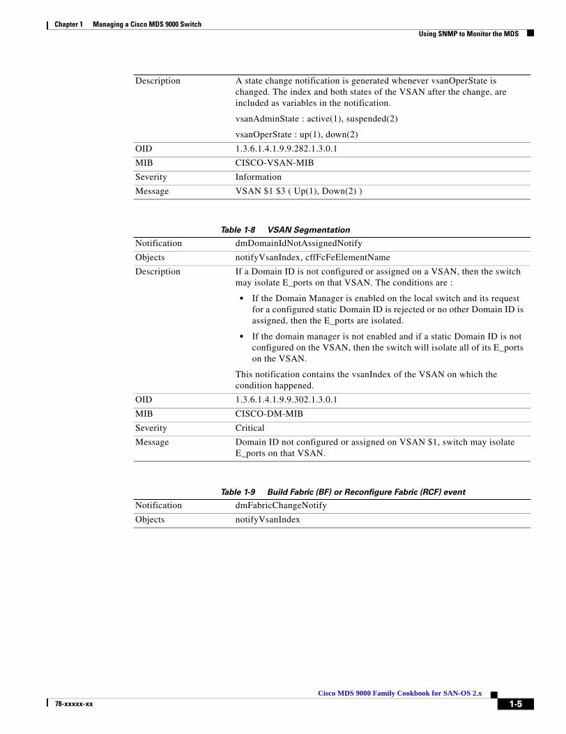
Table 1-8 VSAN Segmentation
Table 1-9 Build Fabric (BF) or Reconfigure Fabric (RCF) event
Description A state change notification is generated whenever vsanOperState is changed. The index and both states of the VSAN after the change, are included as variables in the notification.
vsanAdminState : active(1), suspended(2)
vsanOperState : up(1), down(2)
OID 1.3.6.1.4.1.9.9.282.1.3.0.1
MIB CISCO-VSAN-MIB
Severity Information
Message VSAN $1 $3 ( Up(1), Down(2) )
Notification dmDomainIdNotAssignedNotify
Objects notifyVsanIndex, cffFcFeElementName
Description If a Domain ID is not configured or assigned on a VSAN, then the switch may isolate E_ports on that VSAN. The conditions are :
• If the Domain Manager is enabled on the local switch and its request for a configured static Domain ID is rejected or no other Domain ID is assigned, then the E_ports are isolated.
• If the domain manager is not enabled and if a static Domain ID is not configured on the VSAN, then the switch will isolate all of its E_ports on the VSAN.
This notification contains the vsanIndex of the VSAN on which the condition happened.
OID 1.3.6.1.4.1.9.9.302.1.3.0.1
MIB CISCO-DM-MIB
Severity Critical
Message Domain ID not configured or assigned on VSAN $1, switch may isolate E_ports on that VSAN.
Notification dmFabricChangeNotify
Objects notifyVsanIndex
1-5Cisco MDS 9000 Family Cookbook for SAN-OS 2.x
78-xxxxx-xx
Chapter 1 Managing a Cisco MDS 9000 Switch Using SNMP to Monitor the MDS
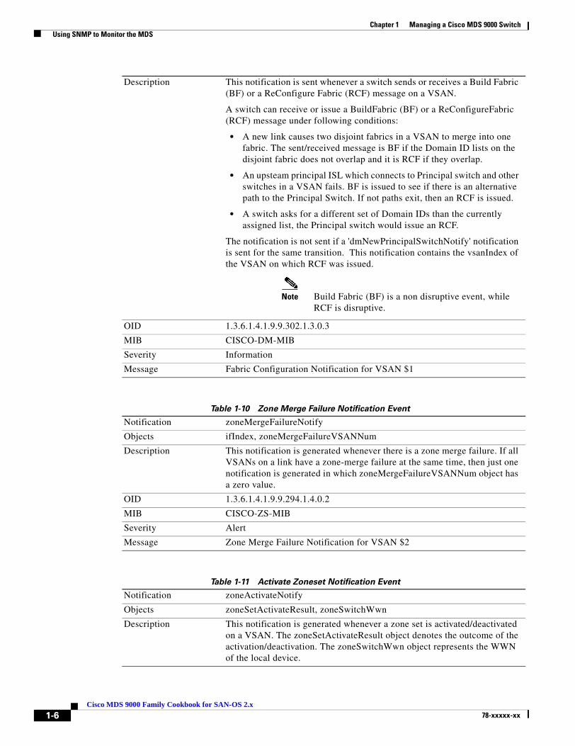
Table 1-10 Zone Merge Failure Notification Event
Table 1-11 Activate Zoneset Notification Event
Description This notification is sent whenever a switch sends or receives a Build Fabric (BF) or a ReConfigure Fabric (RCF) message on a VSAN.
A switch can receive or issue a BuildFabric (BF) or a ReConfigureFabric (RCF) message under following conditions:
• A new link causes two disjoint fabrics in a VSAN to merge into one fabric. The sent/received message is BF if the Domain ID lists on the disjoint fabric does not overlap and it is RCF if they overlap.
• An upsteam principal ISL which connects to Principal switch and other switches in a VSAN fails. BF is issued to see if there is an alternative path to the Principal Switch. If not paths exit, then an RCF is issued.
• A switch asks for a different set of Domain IDs than the currently assigned list, the Principal switch would issue an RCF.
The notification is not sent if a 'dmNewPrincipalSwitchNotify' notification is sent for the same transition. This notification contains the vsanIndex of the VSAN on which RCF was issued.
Note Build Fabric (BF) is a non disruptive event, while RCF is disruptive.
OID 1.3.6.1.4.1.9.9.302.1.3.0.3
MIB CISCO-DM-MIB
Severity Information
Message Fabric Configuration Notification for VSAN $1
Notification zoneMergeFailureNotify
Objects ifIndex, zoneMergeFailureVSANNum
Description This notification is generated whenever there is a zone merge failure. If all VSANs on a link have a zone-merge failure at the same time, then just one notification is generated in which zoneMergeFailureVSANNum object has a zero value.
OID 1.3.6.1.4.1.9.9.294.1.4.0.2
MIB CISCO-ZS-MIB
Severity Alert
Message Zone Merge Failure Notification for VSAN $2
Notification zoneActivateNotify
Objects zoneSetActivateResult, zoneSwitchWwn
Description This notification is generated whenever a zone set is activated/deactivated on a VSAN. The zoneSetActivateResult object denotes the outcome of the activation/deactivation. The zoneSwitchWwn object represents the WWN of the local device.
1-6Cisco MDS 9000 Family Cookbook for SAN-OS 2.x
78-xxxxx-xx
Chapter 1 Managing a Cisco MDS 9000 Switch Using SNMP to Monitor the MDS
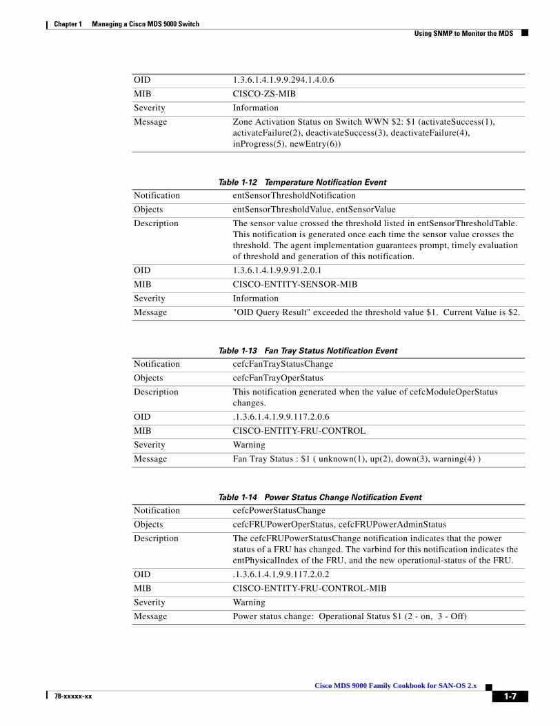
Table 1-12 Temperature Notification Event
Table 1-13 Fan Tray Status Notification Event
Table 1-14 Power Status Change Notification Event
OID 1.3.6.1.4.1.9.9.294.1.4.0.6
MIB CISCO-ZS-MIB
Severity Information
Message Zone Activation Status on Switch WWN $2: $1 (activateSuccess(1), activateFailure(2), deactivateSuccess(3), deactivateFailure(4), inProgress(5), newEntry(6))
Notification entSensorThresholdNotification
Objects entSensorThresholdValue, entSensorValue
Description The sensor value crossed the threshold listed in entSensorThresholdTable. This notification is generated once each time the sensor value crosses the threshold. The agent implementation guarantees prompt, timely evaluation of threshold and generation of this notification.
OID 1.3.6.1.4.1.9.9.91.2.0.1
MIB CISCO-ENTITY-SENSOR-MIB
Severity Information
Message "OID Query Result" exceeded the threshold value $1. Current Value is $2.
Notification cefcFanTrayStatusChange
Objects cefcFanTrayOperStatus
Description This notification generated when the value of cefcModuleOperStatus changes.
OID .1.3.6.1.4.1.9.9.117.2.0.6
MIB CISCO-ENTITY-FRU-CONTROL
Severity Warning
Message Fan Tray Status : $1 ( unknown(1), up(2), down(3), warning(4) )
Notification cefcPowerStatusChange
Objects cefcFRUPowerOperStatus, cefcFRUPowerAdminStatus
Description The cefcFRUPowerStatusChange notification indicates that the power status of a FRU has changed. The varbind for this notification indicates the entPhysicalIndex of the FRU, and the new operational-status of the FRU.
OID .1.3.6.1.4.1.9.9.117.2.0.2
MIB CISCO-ENTITY-FRU-CONTROL-MIB
Severity Warning
Message Power status change: Operational Status $1 (2 - on, 3 - Off)
1-7Cisco MDS 9000 Family Cookbook for SAN-OS 2.x
78-xxxxx-xx
Chapter 1 Managing a Cisco MDS 9000 Switch CFS: Cisco Fabric Services
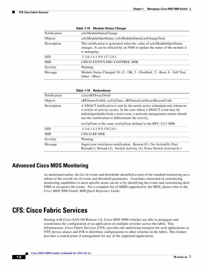
Table 1-15 Module Status Change
Table 1-16 Redundancy
Advanced Cisco MDS MonitoringAs mentioned earlier, the list of events and thresholds identified as part of the standard monitoring are a subset of the overall set of events and threshold parameters. Customers interested in customizing monitoring capabilities to meet specific needs can do so by identifying the events and customizing their NMS to recognize the events. For a complete list of MIBS supported by the MDS, please refer to the Cisco MDS 9000 Family MIB Quick Reference Guide.
CFS: Cisco Fabric ServicesStarting with Cisco SAN-OS Release 2.0, Cisco MDS 9000 switches are able to propagate and synchronize the configuration of an application on multiple switches across the fabric. This infrastructure, Cisco Fabric Services (CFS), provides the underlying transport for such applications as NTP, device-aliases and IVR to distribute configurations to other switches in the fabric. This feature provides a central point of management for any of the supported applications.
Notification cefcModuleStatusChange
Objects cefcModuleOperStatus, cefcModuleStatusLastChangeTime
Description This notification is generated when the value of cefcModuleOperStatus changes. It can be utilized by an NMS to update the status of the module it is managing.
OID .1.3.6.1.4.1.9.9.117.2.0.1
MIB CISCO-ENTITY-FRU-CONTROL-MIB
Severity Warning
Message Module Status Changed: $1 (2 - OK, 3 - Disabled , 5 - Boot, 6 - Self Test, Other - Misc)
Notification cciscoRFSwactNotif
Objects cRFStatusUnitId, sysUpTime, cRFStatusLastSwactReasonCode
Description A SWACT notification is sent by the newly active redundant unit whenever a switch of activity occurs. In the case where a SWACT event may be indistinguishable from a reset event, a network management station should use this notification to differentiate the activity.
sysUpTime is the same sysUpTime defined in the RFC-1213 MIB.
OID .1.3.6.1.4.1.9.9.176.2.0.1
MIB CISCO-RF-MIB
Severity Warning
Message Supervisor switchover notification. Reason $3 ( No Action(0), Peer Reload(1), Reload (2), Switch Activity (3), Force Switch Activity(4) )
1-8Cisco MDS 9000 Family Cookbook for SAN-OS 2.x
78-xxxxx-xx

Chapter 1 Managing a Cisco MDS 9000 Switch CFS: Cisco Fabric Services
Prior to SAN-OS 2.0, on each switch in the fabric, the administrator either had to configure manually, use host based scripting or use Fabric Manager. With CFS, the administrator executes commands from one switch and they are distributed to the rest of the switches in the fabric. In addition, the CFS protocol provides application locking so that two admins can not simultaneously perform configuration changes to the same application.
Cisco Fabric Services uses common terminology across its supported applications:
• Pending Database: When configuration changes are made to a CFS application, they are first made to the pending database then distributed to all switches in the fabric.To activate these changes into the switch’s running configuration, execute an explicit commit command. Alternatively, you can clear the application’s pending database by issuing an explicit abort command.
• Locking: Prior to modifying the pending database, the application uses the CFS transport to obtain a lock, thus preventing other users and switches from modifying the pending database. Applications outside the scope of the lock can still be modified.
– When initializing the configuration, the application first attempts to obtain a lock. The CFS infrastructure knows which switch and user has obtained the lock.
• Scope: The scope of an application can be either Physical or Logical. This determines whether multiple users can simultaneously modify the same application.
– A physical scope encompasses all the switches in the physical fabric such as NTP. While an NTP lock is active, no other user can modify NTP within the physical fabric.
– A logical scope encompasses only the VSAN being configured. For example, port security could be locked in a VSAN. While that port security lock is active, no other user can modify port security for that particular VSAN. However, port security could be modified for another VSAN since it is outside of the scope of the lock.
• Merge Control: If two fabrics are merged, each application is responsible for merging its configuration with that of the same application in the other physical fabric. The basic rule for merging is that a union of the two configurations is produced. However, conflicting entries are not merged. Conflicting entries must be manually created in the merged configuration.
Note Failure to fully merge a CFS application when merging two fabrics, will NOT isolate the ISL.
Tip If CFS is used with an application, all the switches in the fabric should be configured to use CFS for that application. For example, if there are five switches in a fabric, and NTP will be configured leveraging CFS, all five switches should have NTP leveraging CFS.
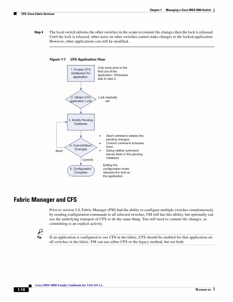
As illustrated in Figure 1-1, a CFS application works this way:
Step 1 Prior to the first configuration, CFS enables distribution for the application, then enters configuration mode for the specified application.
Step 2 The local switch requests an application lock from the other switches in the fabric according to the scope of the application (VSAN or physical). If available, other switches grant the lock to the local switch. If the lock is not available, access to the application’s pending database is denied.
Step 3 Changes are made to the pending database. The changes are then either explicitly committed or aborted.
1-9Cisco MDS 9000 Family Cookbook for SAN-OS 2.x
78-xxxxx-xx
Chapter 1 Managing a Cisco MDS 9000 Switch CFS: Cisco Fabric Services
Step 4 The local switch informs the other switches in the scope to commit the changes then the lock is released. Until the lock is released, other users on other switches cannot make changes to the locked application. However, other applications can still be modified.
Figure 1-1 CFS Application Flow
Fabric Manager and CFSPrior to version 2.0, Fabric Manager (FM) had the ability to configure multiple switches simultaneously by sending configuration commands to all selected switches. FM still has this ability, but optionally can use the underlying transport of CFS to do the same thing. You still need to commit the changes, as committing is an explicit activity.
Tip If an application is configured to use CFS in the fabric, CFS should be enabled for that application on all switches in the fabric. FM can use either CFS or the legacy method, but not both.
1-10Cisco MDS 9000 Family Cookbook for SAN-OS 2.x
78-xxxxx-xx

Chapter 1 Managing a Cisco MDS 9000 Switch CFS: Cisco Fabric Services
How does this work?
If Fabric Manager uses CFS to distribute a configuration, one switch performs the locking and distribution. This switch is referred to as the master switch (see Figure 1-2). The master switch is determined by its WWN – the switch with the lowest WWN becomes the master switch.
Figure 1-2 CFS Master in FabricManager
CFS CLI CommandsYou don’t usually interact with CFS directly, since it is an underlying structure. Instead, you use applications that leverage CFS, for example NTP or DPVM. It is more important to know the status of an NTP merge or commit than to know how CFS is set up. However, there are some situations when only CFS can provide needed information.
Which switches are CFS capable?
Show CFS Peers lists switches that can use CFS.
172.22.36.9# show cfs peers
Physical Fabric-------------------------------------------------- Switch WWN IP Address-------------------------------------------------- 20:00:00:05:30:00:86:9e 172.22.36.9 [Local] 20:00:00:05:30:00:68:5e 172.22.36.11 20:00:00:0d:ec:02:1d:40 172.22.36.8 20:00:00:0c:85:e9:d2:c0 172.22.36.142
Total number of entries = 4
1-11Cisco MDS 9000 Family Cookbook for SAN-OS 2.x
78-xxxxx-xx

Chapter 1 Managing a Cisco MDS 9000 Switch CFS: Cisco Fabric Services
What CFS applications do I have and what is their scope?
Show CFS Application Cisco applications utilizing CFS.
172.22.36.9# show cfs application
------------------------------------------- Application Enabled Scope------------------------------------------- ntp Yes Physical sfm Yes Physical/Logical fscm Yes Physical role No Physical radius No Physical tacacs No Physical fctimer No Physical syslogd No Physical callhome No Physical device-alias Yes Physical port-security No Logical
Total number of entries = 11
Note • Remember that a physical scope spans all switches physically connected together, regardless of VSAN configuration. Logical scope applies only to the VSAN for a configuration.
• SFM is the SCSI Flow Manager, used to monitor SCSI flows with the Storage Services Module.
• FSCM is the Fabric Startup Configuration Manager that enables the startup copy running-config startup-config fabric.
Why am I locked out of an application by CFS?
CFS provides locking (physical or logical). If the lock is already in use, you see the error Failed to acquire lock.
172.22.36.9(config)# ntp peer 172.22.36.99Failed to acquire Lock
To find out which user (on which switch) has the lock, enter the command show cfs lock.
172.22.36.9# show cfs lock
Application: ntpScope : Physical-------------------------------------------------------------------- Switch WWN IP Address User Name User Type-------------------------------------------------------------------- 20:00:00:0c:85:e9:d2:c0 172.22.36.142 admin CLI/SNMP v3
Total number of entries = 1
Until the current user either commits changes to the database or their lock expires, you cannot modify the pending database unless you break the lock. The command Clear npt session clears the pending database and all pending changes for the specified application are lost.
172.22.36.9# clear ntp session
1-12Cisco MDS 9000 Family Cookbook for SAN-OS 2.x
78-xxxxx-xx

Chapter 1 Managing a Cisco MDS 9000 Switch Command Scheduler
Command SchedulerThis section provides recipes for using the switch command scheduler.
Automated Switch Configuration BackupPrior to SAN-OS 2.0, the only method for automated backup of a switch configuration was to set up a management station to periodically log into the switch and issue appropriate scripting commands to copy the configuration to a TFTP server. The drawback of this method is that, if the management station goes down, the configuration is not backed up.
Command Scheduler can now be used to regularly backup switch configuration to a TFTP server.
In this example, the following resources are used:
• Switch: 172.22.36.142
• TFTP Server: 171.71.58.69
• Schedule: “nightly_10pm” Every night at 10PM.
Step 1 Enable the command scheduler with the scheduler enable command.
ca-9506# config terminalEnter configuration commands, one per line. End with CNTL/Z.ca-9506(config)# scheduler enable
Step 2 Define the job to be run. Do this by saving the running configuration and then copying it to a TFTP server. The {config-job} prompt is the same as the switch exec-mode prompt. Therefore, any command on the switch can also be executed.
ca-9506(config)# scheduler job name backup_configca-9506(config-job)# copy running-config startup-configca-9506(config-job)# copy startup-config tftp://171.71.58.69/ca-9506_config
Step 3 Display the defined job with the show scheduler command.
ca-9506# show scheduler job name backup_configJob Name: backup_config----------------------- copy running-config startup-config copy startup-config tftp://171.71.58.69/ca-9506/ca-9506_config==============================================================================
Step 4 Create the schedule. Assign the time (20:00) and the job that will be assigned to it (backup_config).
ca-9506# conf terminalEnter configuration commands, one per line. End with CNTL/Z.ca-9506(config)# scheduler schedule name nightly_10pm ca-9506(config-schedule)# time daily 20:00ca-9506(config-schedule)# job name backup_config
1-13Cisco MDS 9000 Family Cookbook for SAN-OS 2.x
78-xxxxx-xx
Chapter 1 Managing a Cisco MDS 9000 Switch Command Scheduler
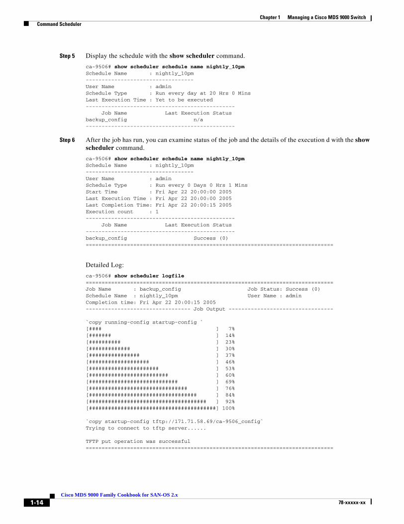
Step 5 Display the schedule with the show scheduler command.
ca-9506# show scheduler schedule name nightly_10pmSchedule Name : nightly_10pm----------------------------------User Name : adminSchedule Type : Run every day at 20 Hrs 0 MinsLast Execution Time : Yet to be executed----------------------------------------------- Job Name Last Execution Statusbackup_config n/a-----------------------------------------------
Step 6 After the job has run, you can examine status of the job and the details of the execution d with the show scheduler command.
ca-9506# show scheduler schedule name nightly_10pmSchedule Name : nightly_10pm----------------------------------User Name : adminSchedule Type : Run every 0 Days 0 Hrs 1 MinsStart Time : Fri Apr 22 20:00:00 2005Last Execution Time : Fri Apr 22 20:00:00 2005Last Completion Time: Fri Apr 22 20:00:15 2005Execution count : 1----------------------------------------------- Job Name Last Execution Status-----------------------------------------------backup_config Success (0)==============================================================================
Detailed Log:
ca-9506# show scheduler logfile==============================================================================Job Name : backup_config Job Status: Success (0)Schedule Name : nightly_10pm User Name : adminCompletion time: Fri Apr 22 20:00:15 2005--------------------------------- Job Output ---------------------------------
`copy running-config startup-config `[#### ] 7%[####### ] 14%[########## ] 23%[############# ] 30%[################ ] 37%[################### ] 46%[###################### ] 53%[######################### ] 60%[############################ ] 69%[############################### ] 76%[################################## ] 84%[##################################### ] 92%[########################################] 100%
`copy startup-config tftp://171.71.58.69/ca-9506_config`Trying to connect to tftp server......
TFTP put operation was successful==============================================================================
1-14Cisco MDS 9000 Family Cookbook for SAN-OS 2.x
78-xxxxx-xx
Chapter 1 Managing a Cisco MDS 9000 Switch Command Scheduler
Tip • Some TFTP servers may have to be configured to allow overwriting of files.
• To avoid overwriting the previous night configuration, create multiple jobs. Specify each job using a different destination filename (for example, ca-9506_monday, ca-9506-tuesday).
1-15Cisco MDS 9000 Family Cookbook for SAN-OS 2.x
78-xxxxx-xx

Chapter 1 Managing a Cisco MDS 9000 Switch Copying Files to and from a Switch
Copying Files to and from a SwitchYou can move files to and from an MDS switch. These files can be log, configuration or firmware files. There are two methods for copying files to and from the switch, using a Command Line Interface (CLI) and using Fabric Manager.
Copying Files Using the CLIThe CLI offers four protocols for copying files to or from the switch, FTP, SCP, SFTP and TFTP. Since the switch always acts as a client, a session originates at the switch. The switch either pushes files to an external system or pulls files from an external system.
In this example, the following resources are used:
• File Server: 172.22.36.10
• File to be copied to the switch: /etc/hosts
The switch’s copy command supports 4 transfer protocols and twelve different sources for files.
ca-9506# copy ? bootflash: Select source filesystem core: Select source filesystem debug: Select source filesystem ftp: Select source filesystem licenses Backup license files log: Select source filesystem modflash: Select source filesystem nvram: Select source filesystem running-config Copy running configuration to destination scp: Select source filesystem sftp: Select source filesystem slot0: Select source filesystem startup-config Copy startup configuration to destination system: Select source filesystem tftp: Select source filesystem volatile: Select source filesystem
Secure Copy Protocol
SCP (Secure copy) transfers use this syntax:
scp:[//[username@]server][/path]
To copy the file /etc/hosts from the server 172.22.36.10 to the switch destination file hosts.txt ( using the user user1) enter:
switch# copy scp://[email protected]/etc/hosts bootflash:[email protected]'s password:hosts 100% |*****************************| 2035 00:00
1-16Cisco MDS 9000 Family Cookbook for SAN-OS 2.x
78-xxxxx-xx

Chapter 1 Managing a Cisco MDS 9000 Switch Copying Files to and from a Switch
Secure File Transfer Protocol
To back up the switch startup configuration to a SFTP server, enter:
switch# copy startup-config sftp://[email protected]/MDS/startup-configuration.bak1Connecting to [email protected]'s password:switch#
Tip Backing up the startup-configuration to a server should be done on a daily basis and prior to any changes. A short script can be written to be run on the switch to save, then back up, the configuration. The script needs to contain only two commands: copy running-configuration startup-configuration and copy startup-configuration tftp://<server>/<name>. To execute the script use the command run-script <filename>.
1-17Cisco MDS 9000 Family Cookbook for SAN-OS 2.x
78-xxxxx-xx
Chapter 1 Managing a Cisco MDS 9000 Switch Managing Files on the Standby Supervisor
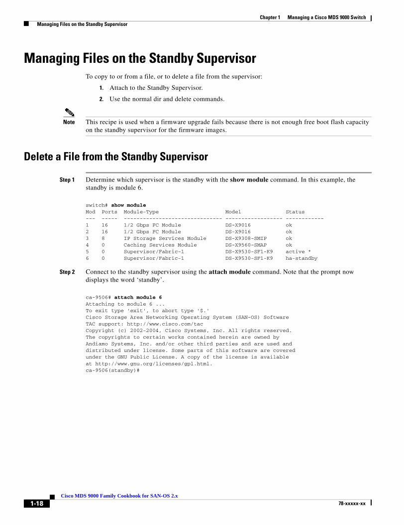
Managing Files on the Standby SupervisorTo copy to or from a file, or to delete a file from the supervisor:
1. Attach to the Standby Supervisor.
2. Use the normal dir and delete commands.
Note This recipe is used when a firmware upgrade fails because there is not enough free boot flash capacity on the standby supervisor for the firmware images.
Delete a File from the Standby Supervisor
Step 1 Determine which supervisor is the standby with the show module command. In this example, the standby is module 6.
switch# show moduleMod Ports Module-Type Model Status--- ----- ------------------------------- ------------------ ------------1 16 1/2 Gbps FC Module DS-X9016 ok2 16 1/2 Gbps FC Module DS-X9016 ok3 8 IP Storage Services Module DS-X9308-SMIP ok4 0 Caching Services Module DS-X9560-SMAP ok5 0 Supervisor/Fabric-1 DS-X9530-SF1-K9 active *6 0 Supervisor/Fabric-1 DS-X9530-SF1-K9 ha-standby
Step 2 Connect to the standby supervisor using the attach module command. Note that the prompt now displays the word ‘standby’.
ca-9506# attach module 6Attaching to module 6 ...To exit type 'exit', to abort type '$.'Cisco Storage Area Networking Operating System (SAN-OS) SoftwareTAC support: http://www.cisco.com/tacCopyright (c) 2002-2004, Cisco Systems, Inc. All rights reserved.The copyrights to certain works contained herein are owned byAndiamo Systems, Inc. and/or other third parties and are used anddistributed under license. Some parts of this software are coveredunder the GNU Public License. A copy of the license is availableat http://www.gnu.org/licenses/gpl.html.ca-9506(standby)#
1-18Cisco MDS 9000 Family Cookbook for SAN-OS 2.x
78-xxxxx-xx

Chapter 1 Managing a Cisco MDS 9000 Switch Managing Files on the Standby Supervisor
Step 3 List the files on the boot flash with the dir command.
ca-9506(standby)# dir bootflash: 12330496 Jun 30 21:11:33 2004 boot-1-3-4a 2035 Jun 17 16:30:18 2004 hosts.txt 43705437 Jun 30 21:11:58 2004 isan-1-3-4a 12288 Dec 31 17:13:48 1979 lost+found/ 12334592 Jun 23 17:02:16 2004 m9500-sf1ek9-kickstart-mz.1.3.4b.bin 43687917 Jun 23 17:02:42 2004 m9500-sf1ek9-mz.1.3.4b.bin 99 Apr 07 19:28:54 1980 security_cnv.log
Usage for bootflash://sup-local 126340096 bytes used 59745280 bytes free 186085376 bytes total
Step 4 Delete the file with the delete command.
ca-9506(standby)# delete bootflash:hosts.txt
Step 5 Enter exit, and the prompt returns to the active supervisor prompt:
ca-9506(standby)# exitrlogin: connection closed.ca-9506#
1-19Cisco MDS 9000 Family Cookbook for SAN-OS 2.x
78-xxxxx-xx
Chapter 1 Managing a Cisco MDS 9000 Switch Firmware Upgrades and Downgrades
Firmware Upgrades and DowngradesUpgrading has not changed from SAN-OS 1.x to SAN-OS 2.x. However, downgrading from SAN-OS 2.x to 1.x is requires special attention.
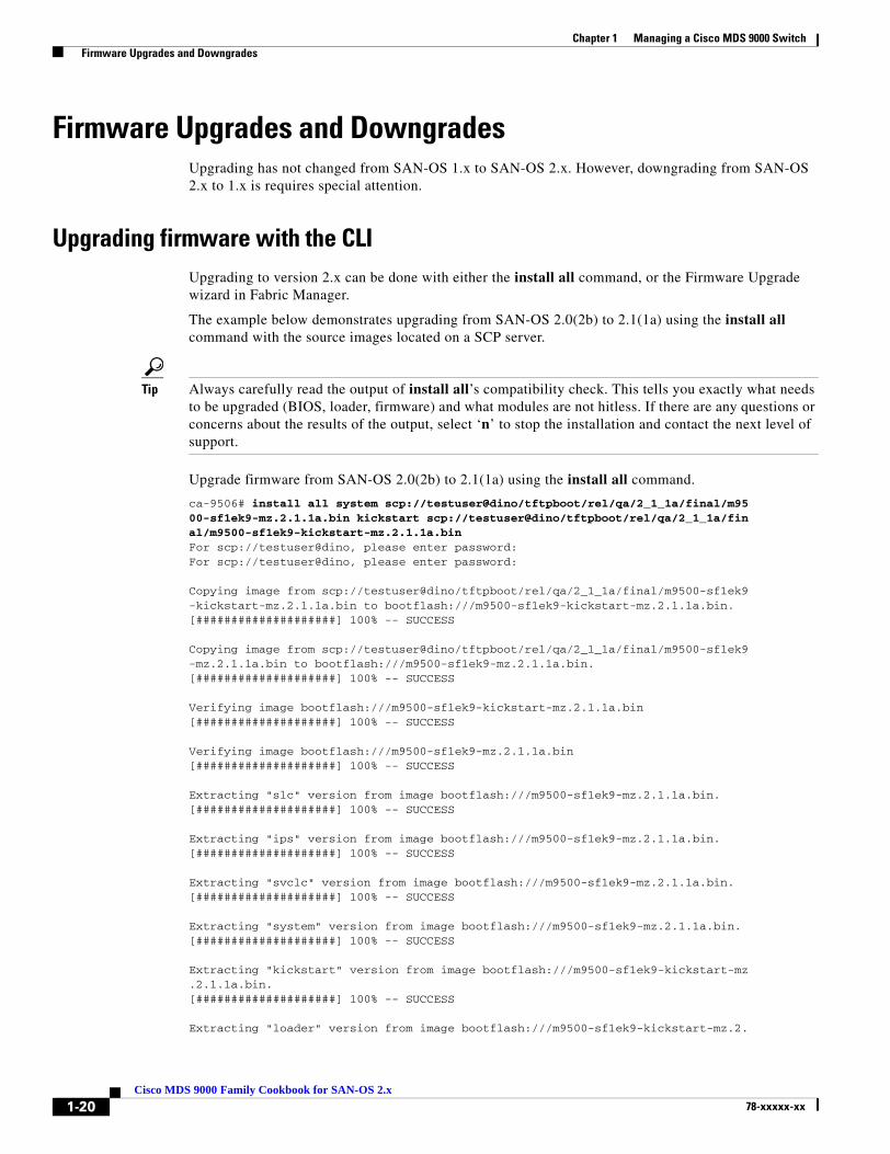
Upgrading firmware with the CLIUpgrading to version 2.x can be done with either the install all command, or the Firmware Upgrade wizard in Fabric Manager.
The example below demonstrates upgrading from SAN-OS 2.0(2b) to 2.1(1a) using the install all command with the source images located on a SCP server.
Tip Always carefully read the output of install all’s compatibility check. This tells you exactly what needs to be upgraded (BIOS, loader, firmware) and what modules are not hitless. If there are any questions or concerns about the results of the output, select ‘n’ to stop the installation and contact the next level of support.
Upgrade firmware from SAN-OS 2.0(2b) to 2.1(1a) using the install all command.
ca-9506# install all system scp://testuser@dino/tftpboot/rel/qa/2_1_1a/final/m9500-sf1ek9-mz.2.1.1a.bin kickstart scp://testuser@dino/tftpboot/rel/qa/2_1_1a/final/m9500-sf1ek9-kickstart-mz.2.1.1a.binFor scp://testuser@dino, please enter password:For scp://testuser@dino, please enter password:
Copying image from scp://testuser@dino/tftpboot/rel/qa/2_1_1a/final/m9500-sf1ek9-kickstart-mz.2.1.1a.bin to bootflash:///m9500-sf1ek9-kickstart-mz.2.1.1a.bin.[####################] 100% -- SUCCESS
Copying image from scp://testuser@dino/tftpboot/rel/qa/2_1_1a/final/m9500-sf1ek9-mz.2.1.1a.bin to bootflash:///m9500-sf1ek9-mz.2.1.1a.bin.[####################] 100% -- SUCCESS
Verifying image bootflash:///m9500-sf1ek9-kickstart-mz.2.1.1a.bin[####################] 100% -- SUCCESS
Verifying image bootflash:///m9500-sf1ek9-mz.2.1.1a.bin[####################] 100% -- SUCCESS
Extracting "slc" version from image bootflash:///m9500-sf1ek9-mz.2.1.1a.bin.[####################] 100% -- SUCCESS
Extracting "ips" version from image bootflash:///m9500-sf1ek9-mz.2.1.1a.bin.[####################] 100% -- SUCCESS
Extracting "svclc" version from image bootflash:///m9500-sf1ek9-mz.2.1.1a.bin.[####################] 100% -- SUCCESS
Extracting "system" version from image bootflash:///m9500-sf1ek9-mz.2.1.1a.bin.[####################] 100% -- SUCCESS
Extracting "kickstart" version from image bootflash:///m9500-sf1ek9-kickstart-mz.2.1.1a.bin.[####################] 100% -- SUCCESS
Extracting "loader" version from image bootflash:///m9500-sf1ek9-kickstart-mz.2.
1-20Cisco MDS 9000 Family Cookbook for SAN-OS 2.x
78-xxxxx-xx
Chapter 1 Managing a Cisco MDS 9000 Switch Firmware Upgrades and Downgrades
1.1a.bin.[####################] 100% -- SUCCESS
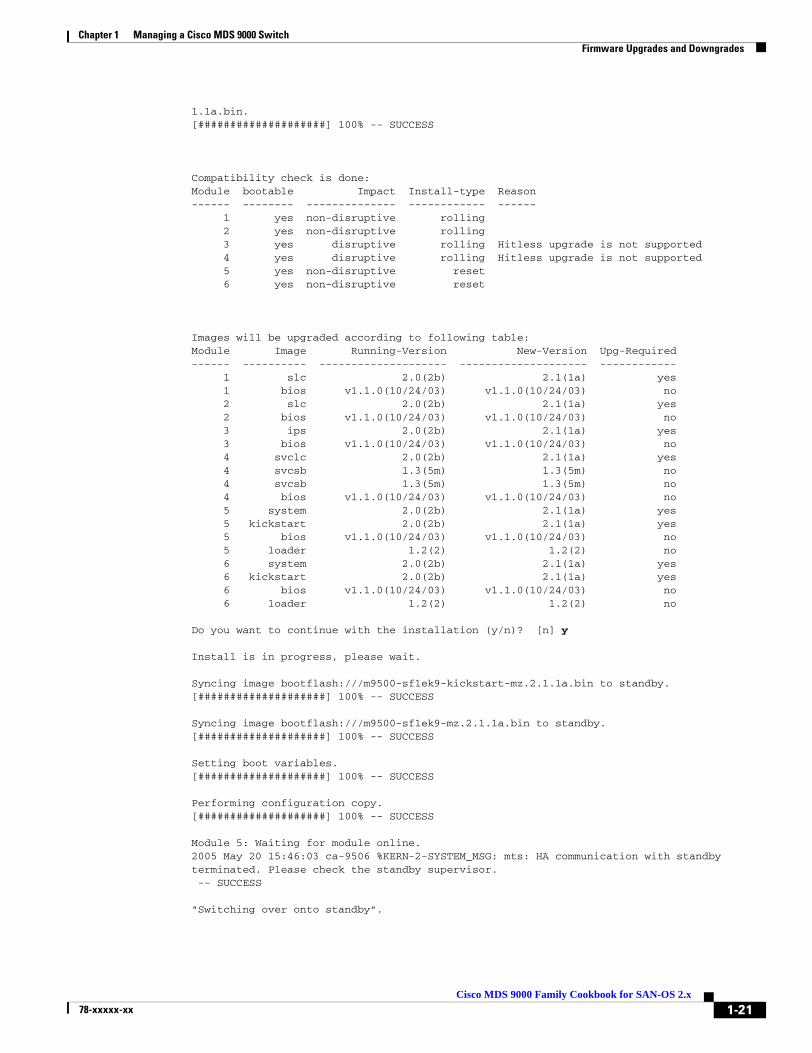
Compatibility check is done:Module bootable Impact Install-type Reason------ -------- -------------- ------------ ------ 1 yes non-disruptive rolling 2 yes non-disruptive rolling 3 yes disruptive rolling Hitless upgrade is not supported 4 yes disruptive rolling Hitless upgrade is not supported 5 yes non-disruptive reset 6 yes non-disruptive reset
Images will be upgraded according to following table:Module Image Running-Version New-Version Upg-Required------ ---------- -------------------- -------------------- ------------ 1 slc 2.0(2b) 2.1(1a) yes 1 bios v1.1.0(10/24/03) v1.1.0(10/24/03) no 2 slc 2.0(2b) 2.1(1a) yes 2 bios v1.1.0(10/24/03) v1.1.0(10/24/03) no 3 ips 2.0(2b) 2.1(1a) yes 3 bios v1.1.0(10/24/03) v1.1.0(10/24/03) no 4 svclc 2.0(2b) 2.1(1a) yes 4 svcsb 1.3(5m) 1.3(5m) no 4 svcsb 1.3(5m) 1.3(5m) no 4 bios v1.1.0(10/24/03) v1.1.0(10/24/03) no 5 system 2.0(2b) 2.1(1a) yes 5 kickstart 2.0(2b) 2.1(1a) yes 5 bios v1.1.0(10/24/03) v1.1.0(10/24/03) no 5 loader 1.2(2) 1.2(2) no 6 system 2.0(2b) 2.1(1a) yes 6 kickstart 2.0(2b) 2.1(1a) yes 6 bios v1.1.0(10/24/03) v1.1.0(10/24/03) no 6 loader 1.2(2) 1.2(2) no
Do you want to continue with the installation (y/n)? [n] y
Install is in progress, please wait.
Syncing image bootflash:///m9500-sf1ek9-kickstart-mz.2.1.1a.bin to standby.[####################] 100% -- SUCCESS
Syncing image bootflash:///m9500-sf1ek9-mz.2.1.1a.bin to standby.[####################] 100% -- SUCCESS
Setting boot variables.[####################] 100% -- SUCCESS
Performing configuration copy.[####################] 100% -- SUCCESS
Module 5: Waiting for module online.2005 May 20 15:46:03 ca-9506 %KERN-2-SYSTEM_MSG: mts: HA communication with standby terminated. Please check the standby supervisor. -- SUCCESS
"Switching over onto standby".
1-21Cisco MDS 9000 Family Cookbook for SAN-OS 2.x
78-xxxxx-xx
Chapter 1 Managing a Cisco MDS 9000 Switch Firmware Upgrades and Downgrades
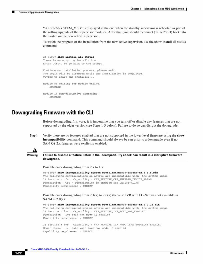
“%Kern-2-SYSTEM_MSG” is displayed at the end when the standby supervisor is rebooted as part of the rolling upgrade of the supervisor modules. After that, you should reconnect (Telnet/SSH) back into the switch on the new active supervisor.
To watch the progress of the installation from the new active supervisor, use the show install all status command.
ca-9506# show install all statusThere is an on-going installation...Enter Ctrl-C to go back to the prompt.
Continue on installation process, please wait.The login will be disabled until the installation is completed.Trying to start the installer...
Module 5: Waiting for module online. -- SUCCESS
Module 1: Non-disruptive upgrading. -- SUCCESS
Downgrading Firmware with the CLIBefore downgrading firmware, it is imperative that you turn off or disable any features that are not supported by the older version (see Steps 1-3 below). Failure to do so can disrupt the downgrade.
Step 1 Verify there are no features enabled that are not supported in the lower level firmware using the show incompatibility command. This command should always be run prior to a downgrade even if no SAN-OS 2.x features were explicitly enabled.
Warning Failure to disable a feature listed in the incompatibility check can result in a disruptive firmware downgrade.
Possible error downgrading from 2.x to 1.x:
ca-9506# show incompatibility system bootflash:m9500-sf1ek9-mz.1.3.5.binThe following configurations on active are incompatible with the system image1) Service : cfs , Capability : CAP_FEATURE_CFS_ENABLED_DEVICE_ALIASDescription : CFS - Distribution is enabled for DEVICE-ALIASCapability requirement : STRICT
Possible error downgrading from 2.1(x) to 2.0(x) (because IVR with FC-Nat was not available in SAN-OS 2.0(x):
ca-9506# show incompatibility system bootflash:m9500-sf1ek9-mz.2.0.2b.binThe following configurations on active are incompatible with the system image1) Service : ivr , Capability : CAP_FEATURE_IVR_FCID_NAT_ENABLEDDescription : ivr fcid-nat mode is enabledCapability requirement : STRICT
2) Service : ivr , Capability : CAP_FEATURE_IVR_AUTO_VSAN_TOPOLOGY_ENABLEDDescription : ivr auto vsan-topology mode is enabledCapability requirement : STRICT
1-22Cisco MDS 9000 Family Cookbook for SAN-OS 2.x
78-xxxxx-xx
Chapter 1 Managing a Cisco MDS 9000 Switch Firmware Upgrades and Downgrades
Step 2 Disable unsupported features using the configuration commands:
ca-9506#ca-9506# conf tEnter configuration commands, one per line. End with CNTL/Z.ca-9506(config)# no device-alias distribute
Step 3 Rerun the incompatibility check to verify that all unsupported features are gone:
ca-9506# show incompatibility system bootflash:m9500-sf1ek9-mz.1.3.5.binNo incompatible configurations
Step 4 Proceed with the downgrade using the install all command as described in Upgrading firmware with the CLI, page 1-20.
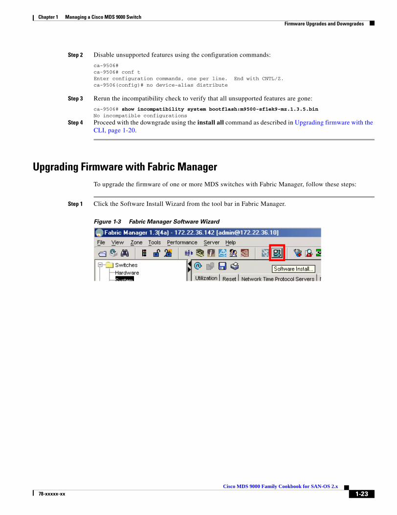
Upgrading Firmware with Fabric ManagerTo upgrade the firmware of one or more MDS switches with Fabric Manager, follow these steps:
Step 1 Click the Software Install Wizard from the tool bar in Fabric Manager.
Figure 1-3 Fabric Manager Software Wizard
1-23Cisco MDS 9000 Family Cookbook for SAN-OS 2.x
78-xxxxx-xx
Chapter 1 Managing a Cisco MDS 9000 Switch Firmware Upgrades and Downgrades
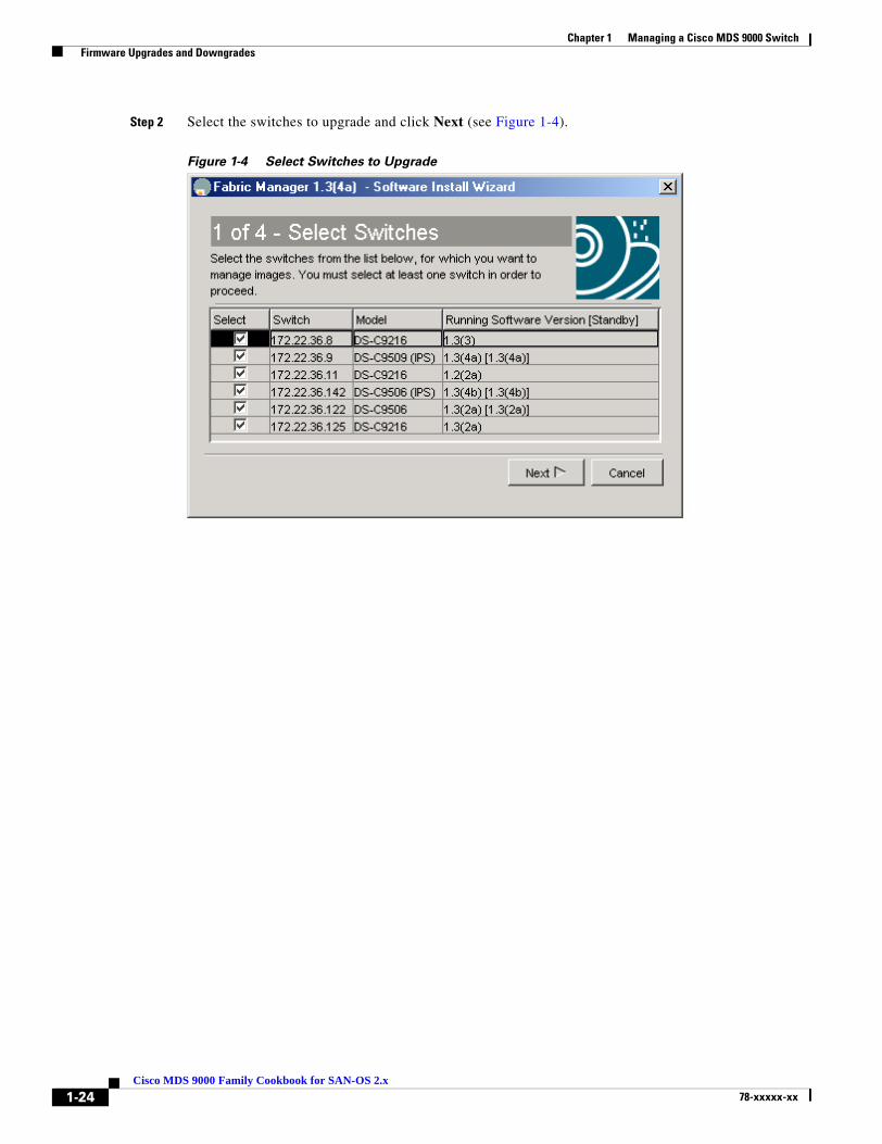
Step 2 Select the switches to upgrade and click Next (see Figure 1-4).
Figure 1-4 Select Switches to Upgrade
1-24Cisco MDS 9000 Family Cookbook for SAN-OS 2.x
78-xxxxx-xx

Chapter 1 Managing a Cisco MDS 9000 Switch Firmware Upgrades and Downgrades
Step 3 Specify the location of the firmware images (see Figure 1-5).
a. Provide the file information to transfer the file from the server to the switch. If the files are to be downloaded during the install, the path and filename of the images must be filled in as well.
b. Select Skip Image Download to upgrade using images already located on the supervisor’s boot flash.
Figure 1-5 Specify Firmware Images
Step 4 Click Next.
Depending on the method for installing (already downloaded to boot flash or download during the install) the wizard may ask for additional file locations. The fourth and final screen provides a summary and lets you start the actual installation.
During installation, a compatibility screen pop-up displays the same version compatibility information that was displayed during the CLI upgrade. Click Yes to continue with the upgrade.
Note Unlike a CLI upgrade, FM maintains connection to the switch and provides detailed upgrade information. You do not have to manually reestablish connectivity to the switch during the supervisor switch-over. If there is a failure, the last screen displays the reasons for a failed upgrade.
1-25Cisco MDS 9000 Family Cookbook for SAN-OS 2.x
78-xxxxx-xx

Chapter 1 Managing a Cisco MDS 9000 Switch Password Recovery
Password RecoveryIf an admin password is lost and there are no other accounts on the switch with either network-admin or user account creation privileges, recover the password for the admin account by following these steps:
Note This procedure requires console access to the switch and requires a reboot of the switch.
Tip Another CLI user with network-admin privileges can change the password of the admin user without reloading the switch.
Step 1 Connect a console cable to the active supervisor of the MDS switch:
Figure 1-6 Console Connection on 9500 and 9200 series MDS switches.
Step 2 Attach the RS-232 end of the console cable to a PC.
1-26Cisco MDS 9000 Family Cookbook for SAN-OS 2.x
78-xxxxx-xx
Chapter 1 Managing a Cisco MDS 9000 Switch Password Recovery
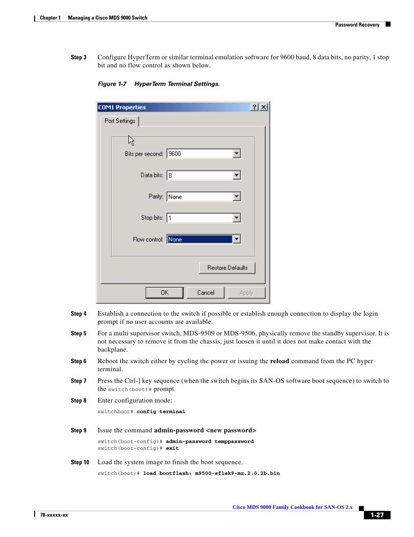
Step 3 Configure HyperTerm or similar terminal emulation software for 9600 baud, 8 data bits, no parity, 1 stop bit and no flow control as shown below.
Figure 1-7 HyperTerm Terminal Settings.
Step 4 Establish a connection to the switch if possible or establish enough connection to display the login prompt if no user accounts are available.
Step 5 For a multi supervisor switch, MDS-9509 or MDS-9506, physically remove the standby supervisor. It is not necessary to remove it from the chassis, just loosen it until it does not make contact with the backplane.
Step 6 Reboot the switch either by cycling the power or issuing the reload command from the PC hyper terminal.
Step 7 Press the Ctrl-] key sequence (when the switch begins its SAN-OS software boot sequence) to switch to the switch(boot)# prompt.
Step 8 Enter configuration mode:
switchboot# config terminal
Step 9 Issue the command admin-password <new password>
switch(boot-config)# admin-password temppasswordswitch(boot-config)# exit
Step 10 Load the system image to finish the boot sequence.
switch(boot)# load bootflash: m9500-sf1ek9-mz.2.0.2b.bin
1-27Cisco MDS 9000 Family Cookbook for SAN-OS 2.x
78-xxxxx-xx
Chapter 1 Managing a Cisco MDS 9000 Switch Password Recovery
Step 11 Log on to the switch using the admin account and the temporary password.
switch login: adminPassword:Cisco Storage Area Networking Operating System (SAN-OS) SoftwareTAC support: http://www.cisco.com/tacCopyright (c) 2002-2004, Cisco Systems, Inc. All rights reserved.The copyrights to certain works contained herein are owned byAndiamo Systems, Inc. and/or other third parties and are used anddistributed under license. Some parts of this software are coveredunder the GNU Public License. A copy of the license is availableat http://www.gnu.org/licenses/gpl.html.switch#
Step 12 Change the admin password to a new permanent password:
ca-9506# config terminalEnter configuration commands, one per line. End with CNTL/Z.ca-9506(config)# username admin password g05ox
Step 13 Save the configuration – this will include the new password.
switch# copy running-config startup-config[########################################] 100%
1-28Cisco MDS 9000 Family Cookbook for SAN-OS 2.x
78-xxxxx-xx
Chapter 1 Managing a Cisco MDS 9000 Switch Installing a License
Installing a LicenseTo run the MDS platform, a license key is required after 120 days. The 120- day grace period is provided to try out new features or resume operation if a replacement chassis needs a license key installed.
Caution If a license grace period expires, all features that depend on that license are disabled even if they are currently running or in production.
You can install a license key using one of two methods, either the command line method or Fabric Manager’s License Installation Wizard. These examples use the switch 172.22.36.10.
Using the CLI to Install a License:
Step 1 Copy the license file to the boot flash of the supervisor:
switch# copy scp://[email protected]/tmp/FM_Server.lic bootflash:[email protected]'s password:FM_Server.lic 100% |*****************************| 2035 00:00
Step 2 Verify the license file with the show license file command.
switch# show license file FM_Server.liclic.lic:SERVER this_host ANYVENDOR ciscoINCREMENT FM_SERVER_PKG cisco 1.0 permanent uncounted \ VENDOR_STRING=MDS HOSTID=VDH=FOX0713037X \ NOTICE="<LicFileID>lic_template</LicFileID><LicLineID>0</LicLineID> \ <PAK>dummyPak</PAK>" SIGN=D8CF07EA26C2
Step 3 Cross reference the switch’s host-id (VDH=FOX0713037X) with the one listed in the license file:
ca-9506# show license host-idLicense hostid: VDH=FOX0713037X
Step 4 Install the license file:
switch# install license bootflash:FM_Server.licInstalling license ..done
Step 5 Verify that the license has been installed with the show license command.
switch# show licenselic.lic:SERVER this_host ANYVENDOR ciscoINCREMENT FM_SERVER_PKG cisco 1.0 permanent uncounted \ VENDOR_STRING=MDS HOSTID=VDH=FOX0713037X \ NOTICE="<LicFileID>lic_template</LicFileID><LicLineID>0</LicLineID> \ <PAK>dummyPak</PAK>" SIGN=D8CF07EA26C2
To display a summary of the installed licenses, use the command show license usage:
switch# show license usageFeature Insta License Status Expiry Date Comments
1-29Cisco MDS 9000 Family Cookbook for SAN-OS 2.x
78-xxxxx-xx

Chapter 1 Managing a Cisco MDS 9000 Switch Installing a License
lled Count-----------------------------------------------------------------FM_SERVER_PKG Yes - In use never -MAINFRAME_PKG No - Unused -ENTERPRISE_PKG Yes - In use never -SAN_EXTN_OVER_IP Yes 2 In use never -SAN_EXTN_OVER_IP_IPS4 No 0 Unused ------------------------------------------------------------------
To determine which features within a license package are being used, specify the package name. In this case QoS is using the Enterprise package:
ca-9506# show license usage ENTERPRISE_PKGApplication-----------Qos Manager-----------
Using Fabric Manager to Install a LicenseTo install the licenses with the Fabric Manager License Wizard, follow these steps:
Step 1 Click the License Install icon shown below to launch the License Installation Wizard.
Figure 1-8 Launching the License Installation Wizard
Step 2 Indicate whether you already have license key files or if you have only a Product Authorization Key (PAK) at this time. If you already have the files, you will be asked to indicate their location. If you have a PAK then the license files will be downloaded and installed from Cisco’s web site. Click Next.
1-30Cisco MDS 9000 Family Cookbook for SAN-OS 2.x
78-xxxxx-xx
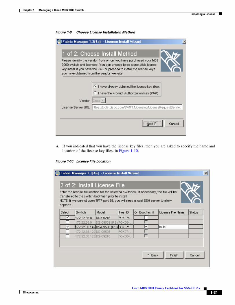
Chapter 1 Managing a Cisco MDS 9000 Switch Installing a License
Figure 1-9 Choose License Installation Method
a. If you indicated that you have the license key files, then you are asked to specify the name and location of the license key files, in Figure 1-10.
Figure 1-10 License File Location
1-31Cisco MDS 9000 Family Cookbook for SAN-OS 2.x
78-xxxxx-xx

Chapter 1 Managing a Cisco MDS 9000 Switch Installing a License
b. If you indicated that you have only the PAK numbers, Fabric Manager will obtain the license files directly from Cisco.com. When you see this screen, provide your Product Authorization Keys.
Figure 1-11 Install License using PAK
Step 3 Click Finish to complete license installation.
1-32Cisco MDS 9000 Family Cookbook for SAN-OS 2.x
78-xxxxx-xx

Chapter 1 Managing a Cisco MDS 9000 Switch Installing a License
Which Feature is Enabling the License Grace Period?When you enable a feature that is licensed but not covered by your current license, you receive syslog, E-mail or other warnings that the feature, for example Fabric Manager Server, has entered its grace period. To determine what features have enabled a specific license, use either the CLI or Fabric manager.
Check with Fabric Manager
In the Physical Attributes Pane, choose Switches then Licenses to see which feature triggered the warning. In the resulting middle pane, choose the Usage tab.
Figure 1-12 License Usage
Check with the CLI
With the CLI, use the command show license usage <license name> to see which feature triggered the warning:
switch1# show license usage ENTERPRISE_PKGApplication-----------SFMQos ManagerPort Security-----------
Once the feature has been identified, either disable it or install a new license.
1-33Cisco MDS 9000 Family Cookbook for SAN-OS 2.x
78-xxxxx-xx

Chapter 1 Managing a Cisco MDS 9000 Switch Copying Core Files From Switch
Copying Core Files From SwitchIf a switch process crashes, it may create a core file to send to Cisco TAC for further troubleshooting. This procedure explains how to retrieve a this core file from the MDS switch.
The resource used in this procedure is FTP Server: 172.22.36.10
Note Use any of the possible methods to copy, including FTP, TFTP, SFTP and SCP.
Step 1 Before copying a core file to another server, identify the PID of the core file with the show cores command.
switch# show coresModule-num Process-name PID Core-create-time---------- ------------ --- ----------------5 fspf 1524 Sep 27 03:11
Step 2 Copy the core file (this example uses FTP) with the copy core command.
"core://<module-number>/<process-id>"
switch# copy core://5/1524 ftp://172.22.36.10/tmp/fspfcore
Send the file to Cisco TAC following the TAC engineer’s directions.
1-34Cisco MDS 9000 Family Cookbook for SAN-OS 2.x
78-xxxxx-xx
Chapter 1 Managing a Cisco MDS 9000 Switch Restoring a Fixed Switch Configuration
Restoring a Fixed Switch ConfigurationThis procedure describes backing up and restoring a switch configuration for one of the MDS 9000 Family fixed configuration switches, such as a 9100 or 9200 series switch. Parts of this procedure are disruptive and should only be done in the event of an emergency, such as the chassis or fixed supervisor needing replacement.
This procedure uses the following resources:
• Old Switch: switch1: (172.22.36.8)
• New Switch: switch2
• File Server: host1
Note Restore a switch configuration only to a switch with the exact same firmware version used to create the switch configuration. If an upgrade is required, first restore the configuration then upgrade the firmware.
Step 1 Save the running configuration with the copy running-config command.
switch1# copy running-config startup-config[########################################] 100%
Step 2 Copy the startup-configuration to the file server using any of the available methods on the switch (FTP, TFTP, SFTP, SCP):
switch1# copy startup-config scp://user@host1/switch1.configuser@switch1's password:sysmgr_system.cfg 100% |*****************************| 10938 00:00switch1#
Step 3 Capture the port assignments using the FLOGI database. This will be used to verify that all of the cables are placed in their correct locations.
switch1# show flogi database---------------------------------------------------------------------------INTERFACE VSAN FCID PORT NAME NODE NAME---------------------------------------------------------------------------fc1/8 600 0x7c0007 50:05:07:63:00:ce:a2:27 50:05:07:63:00:c0:a2:27fc1/13 1001 0xef0001 50:06:0e:80:03:4e:95:13 50:06:0e:80:03:4e:95:13fc1/15 600 0x7c0004 50:06:0b:00:00:13:37:ae 50:06:0b:00:00:13:37:af
Note At this point the old switch is no longer needed; disconnected its mgmt0 port from the LAN.
Step 4 Log on to the new switch using the console connection and clear the switch configuration. Do not run the setup script, if prompted. The write erase command erases the switch’s configuration.
switch2# write eraseWarning: This command will erase the startup-configuration.Do you wish to proceed anyway? (y/n) [n] y
Step 5 Reload the switch.
switch2# reloadThis command will reboot the system. (y/n)? [n] y
1-35Cisco MDS 9000 Family Cookbook for SAN-OS 2.x
78-xxxxx-xx

Chapter 1 Managing a Cisco MDS 9000 Switch Restoring a Fixed Switch Configuration
Step 6 The switch comes up in factory default mode and prompts for basic system configuration. Skip it (CRL-Z) as all the configuration options are contained in the old switch’s startup configuration. Manually configure the IP address.
switch2# config terminalEnter configuration commands, one per line. End with CNTL/Z.switch2(config)# int mgmt 0switch2(config-if)# ip address 172.22.36.8 255.255.254.0switch2(config-if)# no shut
Step 7 If interface (fcX/Y) based zoning was done, obtain the new switch’s wwn with the show wwn switch command. Otherwise, skip this step.
switch2# show wwn switchSwitch WWN is 20:00:00:0d:ec:02:1d:40
Step 8 On the file server, make a copy of the configuration file, then open the copy in a text editor such as Notepad. Make these changes:
a. Remove the lines that contain the SNMP user accounts, as the encrypted passwords are tied to the MAC address of the chassis.:
$ cp switch1.config switch1.config.orig$ vi switch1.config
The user accounts are all grouped together and begin with the command snmp-server user
snmp-server user admin network-admin auth md5 0x46694cac2585d39d3bc00c8a4c7d48a6 localizedkeysnmp-server user guestadmin network-admin auth md5 0xcae40d254218747bc57ee1df34826b51 localizedkey
b. If interface (fcX/Y) based zoning was done, replace the old switch’s wwn in the zone member commands with the new switch’s wwn. If interface zoning was not done, skip this step.
zone name Z_1 vsan 9 member interface fc1/9 swwn 20:00:00:0d:ec:02:1d:40
c. If IVR was configured on this switch, the ivr topology will need to be modified as that is based upon the swwn and the old swwn should be replaced with the new swwn.
ivr vsan-topology database autonomous-fabric-id 1 switch-wwn 20:00:00:0d:ec:02:1d:40 vsan-ranges 500,3002 autonomous-fabric-id 1 switch-wwn 20:00:00:0c:85:e9:d2:c0 vsan-ranges 500,3000
If the IVR topology is configured for auto and is distributed via CFS. Then this step does not need to be done as the switch will learn of the topology via CFS.
Note If there are multiple IVR enabled switches in the fabric, the swwn from the old switch should be removed from ALL of the IVR topologies in the fabric and replaced with the new swwn. This step should be done prior to bringing the new switch online. These modifications can be done on the other switches using either the CLI or Fabric Manager.
d. Save and exit the config file.
Step 9 From the new switch, copy the modified config file from the file server onto the new switch’s running configuration. As the file is copied, it is executed and the configuration is applied. The commands being applied are displayed in single quotes. Any errors resulting from the commands are displayed immediately after the command that caused it. When finished, the prompt changes to reflect the new switch name.
switch2# copy scp://user@host1/switch1.config running-config
1-36Cisco MDS 9000 Family Cookbook for SAN-OS 2.x
78-xxxxx-xx

Chapter 1 Managing a Cisco MDS 9000 Switch Restoring a Fixed Switch Configuration
user@host1's password:switch1.config 100% |*****************************| 10938 00:00
Step 10 Save the configuration by copying the startup config to the running config.switch1# copy running-config startup-config
[########################################] 100%:
Step 11 The switch can now be accessed with the CLI. Complete the configuration restoration:
a. Recreate SNMP user accounts.
b. If the switch is accessed with SSH, remove the MDS switch entry from the host’s known_hosts file because the switch’s public key has changed.
c. Install any required license keys.
Step 12 Move the cables from the old switch to the new switch, using the old switch’s show flogi database as a reference to verify that each cable is in the correct location.
Step 13 Verify that all devices have logged in and all features are running is as they are supposed to be and save the running configuration to the startup configuration with the command copy running-config startup-config.
Step 14 Reload the switch to verify that it boots correctly with the configuration.
1-37Cisco MDS 9000 Family Cookbook for SAN-OS 2.x
78-xxxxx-xx

Chapter 1 Managing a Cisco MDS 9000 Switch Configuring an NTP Server
Configuring an NTP ServerNetwork Time Protocol (NTP) is a protocol used by devices to synchronize their internal clocks with other devices. The switch can only be used as an NTP client and can talk to other NTP systems with a higher stratum (or authority). NTP is hierarchical in nature, so that lower stratum numbers are closer to the source of the time authority. Devices that are at the same stratum can be configured as peers so that they work together to determine the correct time by making minute adjustments. Normally, switches are configured as peers while a router or other dedicated machine is used as a NTP server.
Configuring NTP with CFSCFS (see “CFS: Cisco Fabric Services, page 1-8”) lets you perform a single configuration for NTP and have it propagated to other switches. Also, if a new switch comes online it can be set to inherit the NTP configuration from the existing switches. The new switch merges its configuration (no configuration) with the existing NTP CFS configuration and the result is that the new switch has an NTP configuration.
Note NTP does not set the time zone (or offset from UTC) for the switch; it must be set manually, using for example for Eastern Standard Time and Eastern Daylight-Savings Time:clock timezone EST -5.0 clock summer-time EDT 1 Sunday Apr 02:00 5 Sunday Oct 02:00 60
For this example:
• Switch #1 IP Address: 172.22.36.142
• Switch #2 IP Address: 172.22.36.8
• NTP Server: 171.69.16.26
To configure NTP for switch1, follow these steps:
Step 1 Enter configuration mode and enable CFS distribution for NTP for switches 1 and 2.
a. For switch1:
switch1# conf tEnter configuration commands, one per line. End with CNTL/Z.switch1(config)# ntp distribute
b. For switch2
switch2# conf tEnter configuration commands, one per line. End with CNTL/Z.switch2(config)# ntp distribute
Note Steps 2 through 5 can be done from configuration mode of either switch1 or switch2.
Step 2 Change to configuration mode with the conf t command, then add the NTP server to the configuration.
switch1# conf tswitch1(config)# ntp server 171.69.16.26
Step 3 Add the NTP peer switches to the configuration.
switch1(config)# ntp peer 172.22.36.8
1-38Cisco MDS 9000 Family Cookbook for SAN-OS 2.x
78-xxxxx-xx

Chapter 1 Managing a Cisco MDS 9000 Switch Configuring an NTP Server
switch1(config)# ntp peer 172.22.36.142
Step 4 Commit the NTP configuration and end configuration mode.
switch1(config)# ntp commitswitch1(config)# end
At this point, NTP is configured and the switch will slowly adjust to the new time.
To view the NTP configuration on the local switch, use the show ntp peers command.
switch1# show ntp peers-------------------------------------------------- Peer IP Address Serv/Peer-------------------------------------------------- 172.22.36.142 Peer 171.69.16.26 Server 172.22.36.8 Peer
To view the NTP configuration on the remote switch, use the show ntp peers command.:
switch2# show ntp peers-------------------------------------------------- Peer IP Address Serv/Peer-------------------------------------------------- 172.22.36.142 Peer 171.69.16.26 Server 172.22.36.8 Peer
Step 5 Save the configuration on both switches. CFS can be used to instruct both switches to save their configuration by running copy running-config startup-config. See Saving the Configuration Across the Fabric, page 1-43
switch1# copy running-config startup-config fabric[########################################] 100%
Configure NTP without CFSTo configure NTP without CFS, log on to each switch in the fabric and configure NTP. This is the same procedure used in a SAN-OS 1.x environment.
Note NTP does not set the time zone (or offset from UTC) for the switch. You must set it manually (in this example for Eastern Standard Time and Eastern Daylight-Savings Time):clock timezone EST -5.0 clock summer-time EDT 1 Sunday Apr 02:00 5 Sunday Oct 02:00 60
For this example, these resources are used:
• Switch #1 IP Address: 172.22.36.142
• Switch #2 IP Address: 172.22.36.9
• NTP Server: 171.69.16.26
To configure NTP for switch1, follow these steps:
Step 1 Change to configuration mode with the conf t command then add the NTP server.
switch1# conf t
1-39Cisco MDS 9000 Family Cookbook for SAN-OS 2.x
78-xxxxx-xx
Chapter 1 Managing a Cisco MDS 9000 Switch Configuring an NTP Server
Enter configuration commands, one per line. End with CNTL/Z.switch1(config)# ntp server 171.69.16.26
Step 2 Add the NTP peer switch then end configuration mode.
switch1(config)# ntp peer 172.22.36.9switch1(config)# end
At this point, NTP is configured and the switch will slowly adjust to the new time.
To view the NTP configuration, use the command show ntp peers.
switch1# show ntp peers-------------------------------------------------- Peer IP Address Serv/Peer-------------------------------------------------- 171.69.16.26 Server 172.22.36.9 Peer
1-40Cisco MDS 9000 Family Cookbook for SAN-OS 2.x
78-xxxxx-xx
Chapter 1 Managing a Cisco MDS 9000 Switch What to do Before Calling TAC
What to do Before Calling TACWhen you need to contact the Cisco TAC or OSM for additional assistance, follow these steps. This will reduce the amount of time needed to resolve the issue.
Warning Do not reload the line card or switch until at least Step 1. Some logs and counters are kept in volatile storage and will not survive a reload.
Step 1 Collect switch information and configuration. Do this both before and after the issue has been resolved. The three methods below all have the same result.
a. CLI methods:
• Configure the Telnet/SSH application to log the screen output to a text file and issue the command show tech-support details.
• Issue the command tac-pac <filename> (ex: tac-pac bootflash://showtech.switch1). The tac-pac command redirects the output of ‘show tech-support details’ to a file then gzip the file. If no filename is specified, the file created is volatile:show_tech_out.gz.
• Copy the file from the switch using the procedure Copying Files to and from a Switch, page 1-16.
b. Fabric Manager method: Choose Tools > Show tech support. Fabric manager can capture switch configuration information from multiple switches simultaneously. The file can be saved on a local PC.
c. For IVR related issues capture the output of the command show ivr tech-support.
Step 2 Capture the exact error codes:
a. If the error occurs in Fabric Manager, take a screen shot of the error. In Windows, use ALT+PrintScreen to capture the active window and for the entire desktop press PrintScreen. Then paste this screen shot into a new MSpaint.exe (or similar program) session and save the file.
b. Copy the error from the message log. Display it using either show logging log or, to view the last X lines of the log, show logging last #.
Step 3 Make sure you have answers to these questions before calling TAC:
1. Which switch, HBA, or storage port is having the problem? List the switch firmware, driver versions, operating systems versions and storage device firmware.
2. What is the network topology? (FM/tools ->show tech & save map.)
3. Were you making any changes to the environment (zoning, adding line cards, upgrades) prior to or at the time of this event?
4. Are there other similarly configured devices that could have this problem but do not have?
5. To what is the problem device connected (MDS switch Z, interface x/y)?
6. When did this problem first occur?
7. When did this problem last occur?
8. How often does this problem occur?
9. How many devices have this problem?
10. Have you examined the syslog (show logging log) and accounting log (show accounting log) to see if there are any relevant errors or actions that may have caused this condition?
11. Were any traces or debug outputs captured using such tools as:
1-41Cisco MDS 9000 Family Cookbook for SAN-OS 2.x
78-xxxxx-xx

Chapter 1 Managing a Cisco MDS 9000 Switch What to do Before Calling TAC
a. Fcanalyzer, PAA-2, Ethereal, local or remote SPAN
b. CLI debug commands
c. FC traceroute, FC ping
d. FM/DM SNMP trace
12. What troubleshooting steps have been done?
1-42Cisco MDS 9000 Family Cookbook for SAN-OS 2.x
78-xxxxx-xx

Chapter 1 Managing a Cisco MDS 9000 Switch Saving the Configuration Across the Fabric
Saving the Configuration Across the FabricRather than logging on to every switch using a script or re-launching Fabric Manager each time, propagate the configuration with CFS.
switch# copy running-config startup-config fabric[########################################] 100%
This command takes slightly longer than a single copy running-config startup-config would.When it finishes, all the switches have saved configurations.
1-43Cisco MDS 9000 Family Cookbook for SAN-OS 2.x
78-xxxxx-xx
Chapter 1 Managing a Cisco MDS 9000 Switch How to Disable the Web Server
How to Disable the Web ServerOn the MDS platform, a built-in web server provides a method of downloading and installing Device Manager and Fabric Manager. After installation of these tools, the web server is no longer needed. In fact it is possible to download a specific version of Fabric Manager and Device Manager directly from CCO (http://www.cisco.com) without using the web server at all. However, to increase the security of the MDS platform and IP ACL, the web server can be used to block all access to TCP port 80 of the switch.
The IP ACL that is set up denies access to TCP port 80 on the switch but allows access to all other TCP ports.
Note IP ACLs have an implicit DENY ALL added to the end of an ACL, so at least one permit statement must be used. Otherwise all traffic is denied.
Tip • Whenever using ACLs on mgmt0, first test it using a switch that has console access, in case a typo occurs.
• The commands in this recipe can be integrated into a script by copying the bold commands and pasting them into a CLI session.
To create an IP ACL filter and apply it to the mgmt0 interface, follow these CLI steps:
Step 1 Enter configuration mode then create an access list called ‘disable_webserver’. Notice that the second entry for the access list is a permit any statement.
switch1#conf tswitch1(config)#ip access-list disable_webserver deny tcp any any eq port wwwswitch1(config)#ip access-list disable_webserver permit ip any any
Step 2 Apply the access list to mgmt0.
switch1(config)#interface mgmt0switch1(config-if)#ip access-group disable_webserver in
1-44Cisco MDS 9000 Family Cookbook for SAN-OS 2.x
78-xxxxx-xx

Chapter 1 Managing a Cisco MDS 9000 Switch Device Aliases
Device AliasesDevice aliases provide a plain text name to pWWN mapping. This one-to-one mapping technique was developed to identify devices within the switch environment by labels rather than pWWNs. The device alias can be used in areas such as zoning, QoS, IVR, and throughout Fabric Manager and the Performance Manager utilities. This CFS-aware mapping extends to CLI output, where device aliases are used where appropriate.
Note Some rules for devices aliases are:
• Mapping is one-to-one of pWWN to plain text name.
• The CFS scope is physical.
• A device alias database is not tied to a VSAN so if you move an end device (like an HBA) from one VSAN to another, the device alias still applies.
• The merging of two device alias databases produces a union of the two databases. Conflicts are not imported into the resulting database and must be manually resolved. This will not keep the non-conflicting entries from being merged into the new database. The merge failure will not isolate an ISL.
• The CLI manages device aliases in a central database while Fabric Manager manages them under their respective types (hosts and storage).
• For services that leverage device aliasing (zoning, IVR, QOS, etc.) updating the device alias with a new pWWN does not automatically propagate the new information to the services. To update those services, remove the device, update the device alias, then re-add the device alias to the service.
Tip • Use the plain text name to describe both the host name and HBA instance of the device. For example, host123_lpfc0 or SYMM7890_FA14ab is a better name than just host123 or SYMM7890.
• The device alias can become the basis for a Fabric Manager Enclosure. Device aliases SYMM7890_FA14ab and SYMM7890_FA14ba should be part of the enclosure SYMM7890.
1-45Cisco MDS 9000 Family Cookbook for SAN-OS 2.x
78-xxxxx-xx

Chapter 1 Managing a Cisco MDS 9000 Switch Device Aliases
Manipulating Device Aliases with the CLIDevice aliases can be manipulated with the CLI. These recipes demonstrate how device aliases are integrated into the CLI.
Displaying Device Aliases with the CLI
The CLI can display device aliases in show commands like these:
• Display the nameserver
ca-9506# show fcns database
VSAN 1:--------------------------------------------------------------------------FCID TYPE PWWN (VENDOR) FC4-TYPE:FEATURE--------------------------------------------------------------------------0x620000 N 10:00:00:00:c9:32:8b:a8 (Emulex) scsi-fcp:init [ca-sun1_lpfc0]0x65000a N 10:00:00:00:c9:34:a6:3e (Emulex) [ca-aix1_fcs0]
• Display the active zone set containing IVR and regular zones:
zoneset name nozoneset vsan 501 zone name IVRZ_IvrZone1 vsan 501 pwwn 50:06:0e:80:03:4e:95:23 [HDS20117-c20-9] pwwn 10:00:00:00:c9:32:8b:a8 [ca-sun1_lpfc0]
zone name ca_aix2_HDS vsan 600 pwwn 10:00:00:00:c9:34:a5:94 [ca-aix2_fcs1] pwwn 50:06:0e:80:03:4e:95:23 [HDS20117-c20-8]
• Display the flogi database:
ca-9506# show flogi database---------------------------------------------------------------------------INTERFACE VSAN FCID PORT NAME NODE NAME---------------------------------------------------------------------------fc2/5 1000 0xef0008 50:06:0e:80:03:4e:95:23 50:06:0e:80:03:4e:95:23 [HDS20117-c20-9]
Creating Device Aliases with the CLI
To create a device alias using the CLI, follow these steps. The resources used in the examples are:
• Host: ca-aix1
• HBA Instance: fcs0
• PWWN: 10:00:00:00:c9:34:a6:3e
Step 1 device alias is enabled by default, so enter configuration mode, then the device alias database.
ca-9506# conf terminalEnter configuration commands, one per line. End with CNTL/Z.ca-9506(config)# device-alias databaseca-9506(config-device-alias-db)#
1-46Cisco MDS 9000 Family Cookbook for SAN-OS 2.x
78-xxxxx-xx

Chapter 1 Managing a Cisco MDS 9000 Switch Device Aliases
Step 2 Create an entry for the device alias using the device-alias name command.
ca-9506(config-device-alias-db)# device-alias name ca-aix1_fcs0 pwwn 10:00:00:00 c9:34:a6:3e
Step 3 Display the pending changes with the show device-alias command. “+” means that the entry is being added to the database, while “-” means that it will be removed from the database during CFS commit (Step 4).
ca-9506(config-device-alias-db)# do show device-alias database pending-diff + device-alias name ca-aix1_fcs0 pwwn 10:00:00:00:c9:34:a6:3e
Step 4 Commit the changes with device-alias commit:
ca-9506(config-device-alias-db)# device-alias commitca-9506(config)#
Converting FC Aliases to Device Aliases
FC aliases in an existing MDS environment can be duplicated to device aliases by importing the FC aliases using the CLI. Only those FC aliases that are also valid device aliases will be imported. An FC alias is eligible to be imported/converted if:
• The FC alias represents a pWWN.
• The FC alias represents exactly one device and not a group of devices.
• A device alias with the same name does not already exist.
• A device alias with the same pWWN does not already exist.
Note • While the device alias database is maintained on all switches, it has a physical scope. FC aliases have a VSAN scope and may not be present or replicated to all switches if Full Zoneset Distribution is not enabled. You may have to log on to multiple switches to import all of the FC aliases.
• Importing FC aliases does not automatically update any zones based on FC aliases. The zones must be manually converted to device alias-based zones.
• Importing FC aliases does not delete the FC aliases. The FC aliases need to be manually deleted.
In this example the following FC Aliases will be imported and converted into device aliases:
fcalias name alias123 vsan 1
fcalias name temphost vsan 1 pwwn 11:11:11:11:11:11:11:11
fcalias name temphost vsan 2 pwwn 11:11:11:11:11:11:99:99
fcalias name temphost2 vsan 2 pwwn 11:11:11:11:11:22:22:22
Ineligible FC Aliases are listed in VSAN 1 and 2; these FC Aliases failed to be imported.
1-47Cisco MDS 9000 Family Cookbook for SAN-OS 2.x
78-xxxxx-xx
Chapter 1 Managing a Cisco MDS 9000 Switch Device Aliases
To import and convert FC aliases to device aliases, follow these steps:
Step 1 Enter configuration mode.
switch# conf terminalEnter configuration commands, one per line. End with CNTL/Z.switch(config)#
Step 2 Import the FC aliases with the device-alias import command.
switch(config)# device-alias import fcalias vsan 1-2WARNING: Some fc aliases from the specified VSAN range could not be imported due to conflicts.
a. If a warning is displayed, check the logs to determine which FC aliases did not import:
switch(config)# do show device-alias internal errors1) Event:E_DEBUG, length:111, at 608209 usecs after Wed Sep 14 16:25:13 2005 [109] ddas_import_fcalias(703): CONFLICT: fcalias temphost on vsan 2 has same name as fcalias temphost on vsan 1
2) Event:E_DEBUG, length:127, at 607826 usecs after Wed Sep 14 16:25:13 2005 [109] ddas_import_getnext_alias_resp_handler(1119): not importing alias alias123 from vsan 1 as the number of members are not 1.
The message tells you that VSAN 2’s FC alias temphost was not imported because the name temphost already exists on VSAN 1. Also, alias123 was not imported. Examining FC alias alias123 determines that it is not a valid device alias because it doesn’t have any pWWN members.
b. These conflicts should be resolved by deleting the FC alias alias123 and renaming the conflicting alias temphost.
Note FC aliases might be part of an existing zone, so the appropriate zone(s) should be updated accordingly.
Step 3 Display the pending device alias database to see the newly imported device aliases
switch(config)# do show device-alias database pending-diff + device-alias name temphost2 pwwn 11:11:11:11:11:22:22:22
Step 4 CFS commit the pending changes:
switch(config)# device-alias commit
Device Aliases with Fabric ManagerFabric Manager can use device aliases to provide plain text names in many locations including the map, zoning, and QoS. However, to do this, FM needs to be configured to use device aliases instead of FC aliases. Device aliases can be enabled either during installation or afterward. See Enabling Fabric Manager to use Device Aliases, page 1-49
For example, in the figure below, DPVM is using device aliases to represent the pWWNs in it’s configuration. HDS20117-c20-8 in VSAN 1000 is plugged into switch 172.22.36.11 port fc1/1 is easier to understand than the same description using just a pWWN. In this naming scheme the model (HDS), serial number (20117) cluster (20) and port (8) are all used in the name to specifically describe the device.
1-48Cisco MDS 9000 Family Cookbook for SAN-OS 2.x
78-xxxxx-xx

Chapter 1 Managing a Cisco MDS 9000 Switch Device Aliases
Figure 1-13 DPVM Leveraging device aliases
Enabling Fabric Manager to use Device Aliases
To enable device aliases in FM during installation, check the box Use Global device aliases in place of FC Aliases on the initial installation screen.
To enable device aliases in FM after installation, follow these steps.
SAN-OS versions 2.0 through 2.1(1a)
Step 1 Modify the server.properties file entry to read fabric.globalAlias=true. The default location of this file is C:\Program Files\Cisco Systems\MDS 9000\server.properties.)
# Specify whether to discover device aliases from a global alias server.# Default is false if unspecifed.fabric.globalAlias = true
Step 2 Restart the Fabric Manager service. Note that logging out and back in to FM will not reread the file.
Step 3 Log back into FM.
SAN-OS version 2.1(2) and later
Configure Fabric Manager to use device aliases after installation by checking the Device Alias checkbox under Admin -> Server.
1-49Cisco MDS 9000 Family Cookbook for SAN-OS 2.x
78-xxxxx-xx

Chapter 1 Managing a Cisco MDS 9000 Switch Device Aliases
Creating a Device Alias for an Existing Device
Prior to performing any device alias procedures in Fabric Manager, configure FM to use device aliases. Fabric Manager can use device aliases to provide plain text names in many locations including the map, zoning, and QoS. However, to do this, FM needs to be configured to use device aliases instead of FC aliases. Device aliases can be enabled either during installation or afterward. See the “Enabling Fabric Manager to use Device Aliases” section on page 1-49.
These resources are used in the example:
• Host: ca-aix1
• HBA Instance: fcs0
• PWWN: 10:00:00:00:c9:34:a6:3e
To create a device alias in Fabric Manager for a device already logged into the fabric, follow this recipe:
Step 1 In Fabric Manager’s Physical Attributes pane, expand End Devices.
Step 2 Since the WWN corresponds to a host, choose Hosts. (For a storage device, you would choose Storage.)
Step 3 In the device alias column, enter the device alias for the corresponding pWWN.
Step 4 Click Apply Changes.
Figure 1-14 Creating a device alias with Fabric Manager
1-50Cisco MDS 9000 Family Cookbook for SAN-OS 2.x
78-xxxxx-xx
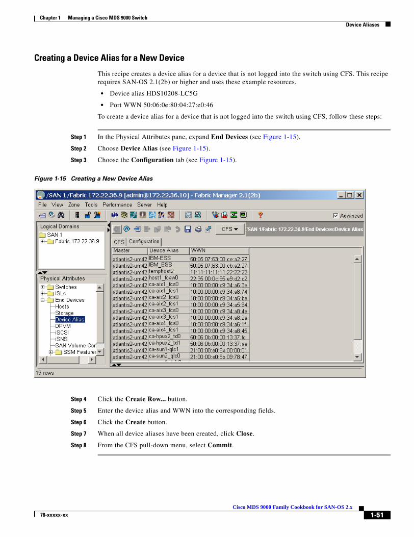
Chapter 1 Managing a Cisco MDS 9000 Switch Device Aliases
Creating a Device Alias for a New Device
This recipe creates a device alias for a device that is not logged into the switch using CFS. This recipe requires SAN-OS 2.1(2b) or higher and uses these example resources.
• Device alias HDS10208-LC5G
• Port WWN 50:06:0e:80:04:27:e0:46
To create a device alias for a device that is not logged into the switch using CFS, follow these steps:
Step 1 In the Physical Attributes pane, expand End Devices (see Figure 1-15).
Step 2 Choose Device Alias (see Figure 1-15).
Step 3 Choose the Configuration tab (see Figure 1-15).
Figure 1-15 Creating a New Device Alias
Step 4 Click the Create Row... button.
Step 5 Enter the device alias and WWN into the corresponding fields.
Step 6 Click the Create button.
Step 7 When all device aliases have been created, click Close.
Step 8 From the CFS pull-down menu, select Commit.
1-51Cisco MDS 9000 Family Cookbook for SAN-OS 2.x
78-xxxxx-xx
Chapter 1 Managing a Cisco MDS 9000 Switch Implementing Syslog
Implementing SyslogThe syslog facility allows the MDS 9000 platform to send a copy of the message log to a host for more permanent storage. This can be useful if the logs need to be examined over a long period of time or if the MDS switch is not accessible.
This example configures an MDS switch to utilize the syslog facility on a Solaris platform. Although a Solaris host is being used, syslog configuration on all UNIX and Linux systems is very similar.
Syslog can discriminate between messages of different severity and handle them differently. For example, messages can be logged to different files or e-mailed to a particular person. Specifying a level of severity determines that all messages of that severity level and greater (lower numbers are greater) are acted upon.
Tip MDS messages should be logged to a different file than the standard syslog file so they are not confused with non-MDS syslog messages. The logfile should not be located on the / filesystem to prevent log messages from filling up the / filesystem.
In this example, these resources are used:
• Syslog Client: switch1
• Syslog Server: 172.22.36.211 (Solaris)
• Syslog facility: local1
• Syslog severity: notifications (level 5, the default)
• File to log MDS messages to: /var/adm/MDS_logs
To configure an MDS switch to utilize the syslog facility on a Solaris platform, follow these steps:
Step 1 Enter configuration mode and configure the MDS switch.
switch1# config terminalEnter configuration commands, one per line. End with CNTL/Z.switch1(config)# logging server 172.22.36.211 6 facility local1
Step 2 Display the switch configuration with the show logging server command.
switch1# show logging serverLogging server: enabled{172.22.36.211} server severity: notifications server facility: local1
1-52Cisco MDS 9000 Family Cookbook for SAN-OS 2.x
78-xxxxx-xx

Chapter 1 Managing a Cisco MDS 9000 Switch Implementing Syslog
Step 3 Configure the Syslog server.
a. Modify /etc/syslog.conf to handle local messages. For Solaris, there must be at least one tab between the facility.severity and the action (/var/adm/MDS_logs)
#Below is for the MDS 9000 logginglocal1.notice /var/adm/MDS_logs
b. Create the log file.
#touch /var/adm/MDS_logs
c. Restart syslogd with the commands syslog stop and syslog start.
# /etc/init.d/syslog stop# /etc/init.d/syslog startsyslog service starting.
d. Verify that syslog started
# ps -ef |grep syslogd root 23508 1 0 11:01:41 ? 0:00 /usr/sbin/syslogd
Step 4 Test the syslog server by creating an event on the MDS switch. In this example, port fc1/2 is reset and the information is listed on the syslog server. Notice that the IP address of the switch is listed in brackets
# tail -f /var/adm/MDS_logsSep 17 11:07:41 [172.22.36.142.2.2] : 2004 Sep 17 11:17:29 pacific: %PORT-5-IF_DOWN_INITIALIZING: %$VSAN 1%$ Interface fc1/2 is down (Initializing)Sep 17 11:07:49 [172.22.36.142.2.2] : 2004 Sep 17 11:17:36 pacific: %PORT-5-IF_UP: %$VSAN 1%$ Interface fc1/2 is up in mode TESep 17 11:07:51 [172.22.36.142.2.2] : 2004 Sep 17 11:17:39 pacific: %VSHD-5-VSHD_SYSLOG_CONFIG_I: Configuring console from pts/0 (dhcp-171-71-49-125.cisco.com)
1-53Cisco MDS 9000 Family Cookbook for SAN-OS 2.x
78-xxxxx-xx
Chapter 1 Managing a Cisco MDS 9000 Switch Configuring Call Home
Configuring Call HomeThe following recipes configure MDS switches to send call home e-mail messages for notification of an issue with the switch. These messages can be directed either to a pager service or e-mail account.
What are Alert Groups?Alert groups determine which events are sent to specific destinations by using profiles. For example, a profile may be configured to include the facilities team. When an environmental alert is triggered, all members receive a text message on a pager.
Table 1-17 Default Alert Group Definitions
Alert Group Description Executed Commands
System Events generated by failure of a software system critical to unit operation.
Show tech-support
Show system redundancy status
Environmental Events related to power, fan and temperature.
Show module
Show environment
Line Card Hardware Events related to standard or intelligent line cards
Show tech-support
Supervisor Hardware Events related to supervisor or fabric cards
Show tech-support
License Events related to unlicensed use of licensed features.
Show license all
Show running-config
Inventory Inventory is a non-critical event. Status should be provided whenever a unit is cold booted or when FRUs are inserted or removed.
Show version
RMON Events related to RMON, triggered by Threshold Manager to set alerts.
Syslog-group-port Events related to syslog messages filed by Port Manager when a port goes up or down.
Test User-generated test messages. Show version
Avanti Events related to the IBM Caching Service Module.
Cisco-TAC Events intended for only Cisco TAC.
1-54Cisco MDS 9000 Family Cookbook for SAN-OS 2.x
78-xxxxx-xx

Chapter 1 Managing a Cisco MDS 9000 Switch Configuring Call Home
Configure Call Home to Send All Notifications to a Single E-Mail AddressThe simplest MDS notification strategy is to send an e-mail for all events. E-mail is a better choice than a pager notification because e-mail is not space-limited and can contain full details of the event.
In this recipe, CFS will not be enabled for Call Home.
Note If all the switches use the same Call Home configuration, then CFS should be enabled.
In this example, these assumptions are made:
• Contact: Storage Admins
• Phone Number: 123-456-7890
• Mail Address: [email protected]
• Street Address: 123 Main Street
• Switch’s E-mail address: [email protected]
• Destination E-mail address (who to mail the error to): [email protected]
• SMTP Server: 192.168.1.2
To Configure Call Home to Send All Notifications to a Single E-Mail Address, follow these steps:
Step 1 In Device Manager, from the Admin pull-down menu, choose Events.
Step 2 Choose Call Home... You see the screen in Figure 1-16.
Figure 1-16 Call Home General Tab
1-55Cisco MDS 9000 Family Cookbook for SAN-OS 2.x
78-xxxxx-xx

Chapter 1 Managing a Cisco MDS 9000 Switch Configuring Call Home
Step 3 Complete the appropriate fields (see Figure 1-16). The Device Service Priority you select will be included in E-mail notifications.
Step 4 Check the Enable checkbox (see Figure 1-16).
Step 5 Click Apply (see Figure 1-16).
Step 6 Choose the Email Setup tab (see Figure 1-17).
Step 7 Complete the From and SMTP fields (see Figure 1-17).
Figure 1-17 Call Home E-mail Setup
Step 8 Click Apply (see Figure 1-17).
Step 9 Choose the Profiles tab (see Figure 1-18). A profile determines what types of notifications are sent.
Step 10 Click Create... (see Figure 1-18)
Step 11 Enter a name for the profile (see Figure 1-18).
Step 12 Select the message level debug (see Figure 1-18)
Step 13 Select MaxMessageSize 0 (zero limit to message size) See Figure 1-18.
Step 14 Check all of the Alert Groups. (See What are Alert Groups?, page 1-54 for more information on Alert Groups). See Figure 1-18.
Note • If you do not have an IBM Caching Service Module installed, uncheck Avanti.
• If you do not want to receive a Call Home message every time a port goes up or down, uncheck syslogGroupPort.
1-56Cisco MDS 9000 Family Cookbook for SAN-OS 2.x
78-xxxxx-xx

Chapter 1 Managing a Cisco MDS 9000 Switch Configuring Call Home
Figure 1-18 Call Home Profile
Step 15 Click Create... (see Figure 1-18)
Step 16 Choose the Destinations tab (see Figure 1-19).
Step 17 Click Create... (see Figure 1-19)
Step 18 Change the profile to the one you just created in the Profiles tab.
Note • Use XML if the Call Home message’s destination is Cisco TAC.
• Use full_txt if the Call Home message will be read as an E-mail.
• Use short_txt if the Call Home message is destined for a pager or similar device.
Step 19 Enter the e-mail address for the Call Home message (see Figure 1-19).
Step 20 Click Create... (see Figure 1-19)
Step 21 Click Close (see Figure 1-19).
Figure 1-19 Call Home Destinations
Step 22 Test the configuration by choosing the Alerts tab, the Test action, then clicking Apply (see Figure 1-19). If errors occur, they are displayed in the Failure Cause text box.
1-57Cisco MDS 9000 Family Cookbook for SAN-OS 2.x
78-xxxxx-xx

Chapter 1 Managing a Cisco MDS 9000 Switch Managing Fabric Manager
Managing Fabric ManagerThe recipes in this section are for configuring Fabric Manager Client and Server applications rather than for configuring objects that reside strictly on the switch.
Operating Fabric Manager Through a Firewall using SNMP ProxyWith Fabric Manager Server, a storage administrator can connect to an MDS switch behind a firewall. The Fabric Manager Client application encapsulates the SNMP protocol in TCP which traverses the firewall and connects to the Fabric Manager Server. FMS then forwards the SNMP packets to the switch.
For the Fabric Manager Client to connect to the Fabric Manager Server the following TCP ports must be open on the firewall:
• TCP port 9198. The FM Client uses this TCP port to send encapsulated SNMP packets to the FM Server.
• TCP ports 9099-9200. TCP port 9099 is used for java.rmi.registry.port while the other ports are used for java.rmi.server.remoteObjectPort.
• TCP port 80. This port is used to view the Performance Monitor’s web based statistics.
Additionally, the Fabric Manager Client uses the CLI to obtain information on the switch directly for some features. Therefore, one of these two options should be used to allow the Fabric Manager Client to access the switch.
• TCP port 23 when the Fabric Manager Client has been configured to use Telnet for CLI access into the Cisco MDS switch. This is the default setting for the Fabric Manager Client.
• TCP port 22 when the Fabric Manager Client has been configured to use SSH for CLI access into the Cisco MDS switch. This is the preferred setting for this environment, and the switch must have SSH enabled.
Note All ports that Fabric Manager Client and Server use can be changed in the server.properties file in the directory C:\Program Files\Cisco Systems\MDS 9000.
Configuration using a non-NAT Packet Filter
In this recipe, the Fabric Manager Client is separated from the Fabric Manager Server and Cisco MDS switch by a packet filtering device that does not perform network address translation (NAT). Additionally, the packet filter allows unrestricted access to the external network to any internal device. Last, SSH has been configured on the switch and Telnet has been disabled.
1-58Cisco MDS 9000 Family Cookbook for SAN-OS 2.x
78-xxxxx-xx

Chapter 1 Managing a Cisco MDS 9000 Switch Managing Fabric Manager
In this example, the topology shown inFigure 1-20 is used.
Figure 1-20 SNMP Proxy Topology
To seperate the Fabric Manager Client from the Fabric Manager Server and Cisco MDS switch by a packet filtering device that does not perform network address translation (NAT), follow these steps:
Step 1 Configure the firewall to allow the following TCP connections:
1. TCP port 9198. The FM Client uses this TCP port to send the encapsulated SNMP packets to the FM Server.
2. TCP ports 9099-9200. TCP port 9099 is used for java.rmi.registry.port while the other ports are used for java.rmi.server.remoteObjectPort.
3. TCP port 23. Some features of the FabricManager client require Telnet access into the switch. However, if SSH is enabled on the switch, the FM Client can leverage SSH instead. If SSH is used, then this port is not required.
4. TCP port 80. Used to view the Performance Monitor’s web based statistics.
5. TCP port 22. Should be enabled if Telnet on the switch is disabled and SSH is enabled.
Step 2 Configure the host running the FM Client to reach the network behind the firewall where the FM Server resides. The 10.0.0.0 network is behind the firewall, while 157.11.22.99 is the external IP address of the firewall. This is not the mgmt0 address of the firewall. On a windows host this configuration is accomplished by the following command:
C:\>route add 10.0.0.0 mask 255.255.255.0 157.11.22.99
Step 3 Configure the switch to reach the Fabric Manager Client (157.11.1.50) which is outside of the firewall. The internal IP address (the side facing the switch) of the firewall is 10.0.0.44.
switch(config)# ip route 157.11.1.50 255.255.255.0 10.0.0.44
Step 4 Launch the Fabric Manager Client, and in the login screen, select the “Use SNMP Proxy” checkbox and enter the IP addresses of the Fabric Manager Server and the MDS switch.
1-59Cisco MDS 9000 Family Cookbook for SAN-OS 2.x
78-xxxxx-xx

Chapter 1 Managing a Cisco MDS 9000 Switch Managing Fabric Manager
Performance Manager (PM) using Fabric Manager Server (FMS)Performance Manager (PM) is a licensed feature that is part of Fabric Manager Server (FMS). PM provides historical analysis of SAN statistics and is displayed graphically to a web browser.
Note Performance Manager requires a Fabric Manager Server License. This license is required for all switches on which performance data is gathered.
Fabric Manager Server must be configured to run Performance Manger. Select a host that is always up and has enough storage to gather and store the performance data. The recommendation for monitoring a large (2000 + port) network is a dedicated server with at least a Gigabyte of RAM, running either Microsoft Windows, Linux or Sun Solaris.
A PM data collection configuration is shown below in the recipe.
Launching Performance Manager Configuration from a Host Running FMS
If FM Server is already installed and you are logging in from another host that only runs the FM Client, skip to Step 2.
Step 1 Log on to the server that hosts the FMS application and launch the FM client. During the login process, make sure that the FM Server points to localhost. This is shown in Figure 1-21 with a blue arrow. Indicating localhost determines that the performance data collected is stored locally.
Figure 1-21 Fabric Manager log on Screen
1-60Cisco MDS 9000 Family Cookbook for SAN-OS 2.x
78-xxxxx-xx

Chapter 1 Managing a Cisco MDS 9000 Switch Managing Fabric Manager
Step 2 You can configure FM Server from a host running only the FM Client. During login, make sure that the FM Server points to the host on which FMS is running. The Seed Switch can be any switch in the fabric. An example is shown in Figure 1-22.
After this login, PM data collection configuration is carried out from the FM Client interface.
Figure 1-22 FM log on Screen with FMServer instead of localhost
Step 3 From the FM Performance Management menu, choose Create flows as shown in Figure 1-23.
Figure 1-23 FM Performance --> Create Flows
This launches the Define Traffic Flows screen shown in Figure 1-24. From this screen, select the types of flows to be gathered. You can gather flows from Host to Storage, Storage to Host, Storage to Storage or All flows.
1-61Cisco MDS 9000 Family Cookbook for SAN-OS 2.x
78-xxxxx-xx

Chapter 1 Managing a Cisco MDS 9000 Switch Managing Fabric Manager
In Figure 1-24, all flows on VSAN 2000 (PMVSAN) are being set up for data collection. To change the VSAN selected, click the drop-down arrow to see and select configured VSANs in the fabric.
Figure 1-24 Define Traffic Flows
Step 4 Click Next to see all the possible flows based on your selections in Figure 1-24.
Step 5 The Review Traffic Flows screen shown in Figure 1-25 lists all possible flows in VSAN 2000 (PM_VSAN). Remove any unneeded flows.
Figure 1-25 Review Traffic Flows
Step 6 Click Finish to create the flows for all the entries listed in the Review Traffic Flows on the appropriate switches.
After a flow has been created, create a collection for it from the FM Client.
Note Every time new flows and collections are created, PM services automatically restarts.
1-62Cisco MDS 9000 Family Cookbook for SAN-OS 2.x
78-xxxxx-xx

Chapter 1 Managing a Cisco MDS 9000 Switch Managing Fabric Manager
To create the collection from the FM Client, follow these steps:
Step 7 From the Performance menu and choose Create Collection as shown in Figure 1-26.
Figure 1-26 Performance --> Create Collection
1-63Cisco MDS 9000 Family Cookbook for SAN-OS 2.x
78-xxxxx-xx

Chapter 1 Managing a Cisco MDS 9000 Switch Managing Fabric Manager
This launches the Define Data Collection screen. In this screen, you see all collection types as shown in Figure 1-27.
Figure 1-27 Define Data Collection
In the example in Figure 1-27, the VSAN named VSAN 2000 (PMVSAN) is selected. Data collection is checked for ISLs, Hosts, Storage and Flows. It is also possible to create a single collection for all VSANs by selecting ALL in the VSAN pull-down menu.
1-64Cisco MDS 9000 Family Cookbook for SAN-OS 2.x
78-xxxxx-xx
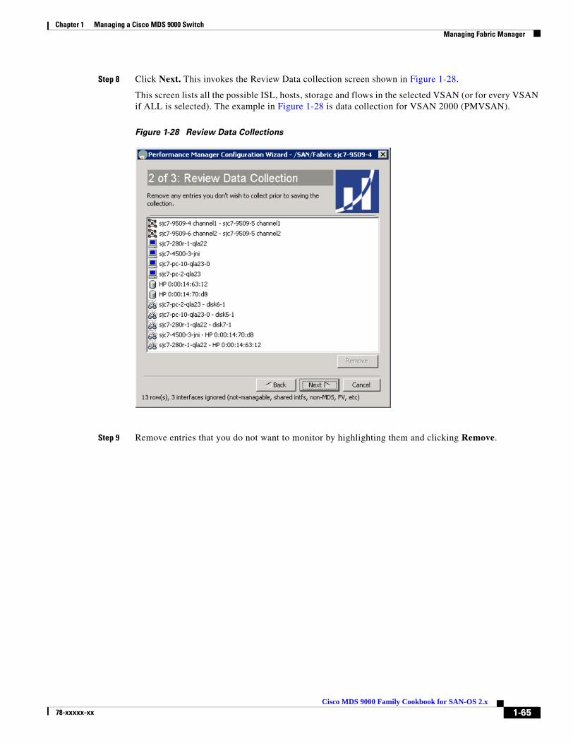
Chapter 1 Managing a Cisco MDS 9000 Switch Managing Fabric Manager
Step 8 Click Next. This invokes the Review Data collection screen shown in Figure 1-28.
This screen lists all the possible ISL, hosts, storage and flows in the selected VSAN (or for every VSAN if ALL is selected). The example in Figure 1-28 is data collection for VSAN 2000 (PMVSAN).
Figure 1-28 Review Data Collections
Step 9 Remove entries that you do not want to monitor by highlighting them and clicking Remove.
1-65Cisco MDS 9000 Family Cookbook for SAN-OS 2.x
78-xxxxx-xx
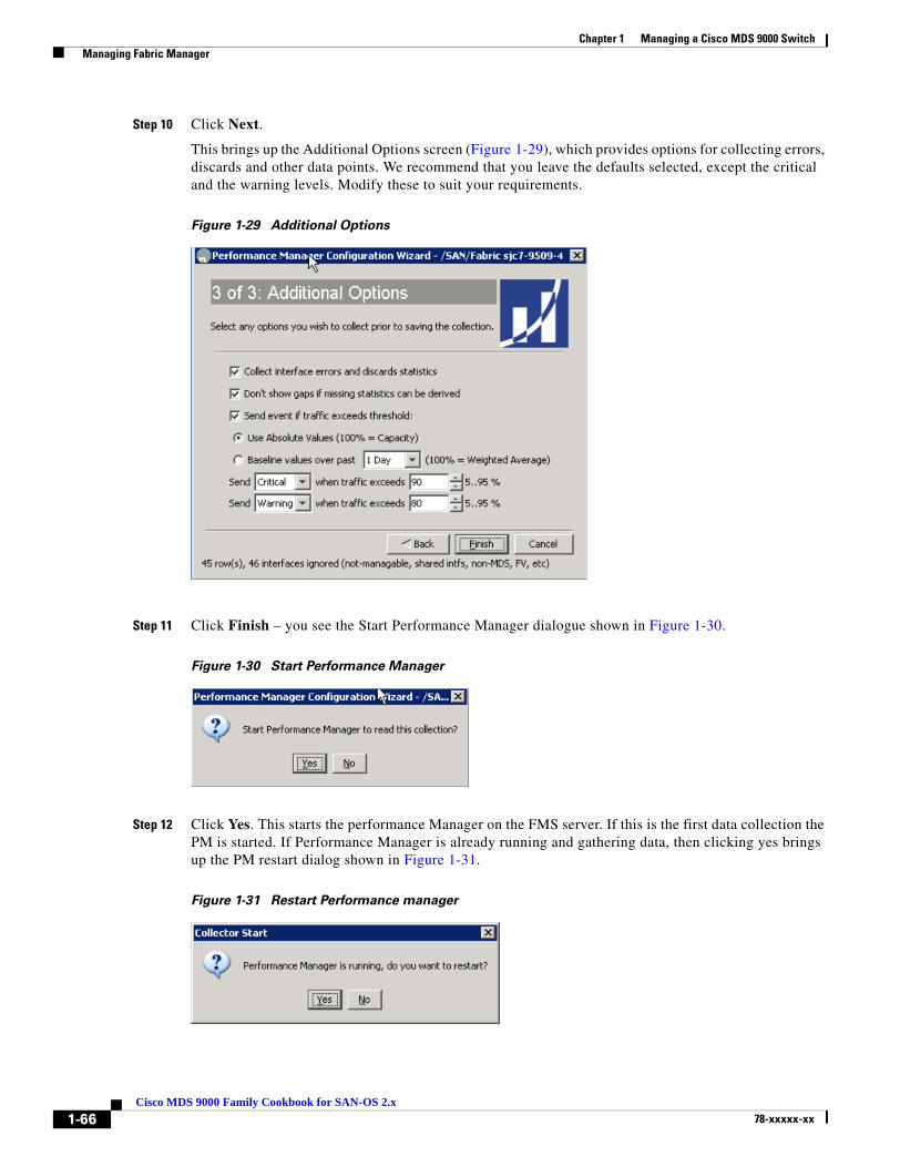
Chapter 1 Managing a Cisco MDS 9000 Switch Managing Fabric Manager
Step 10 Click Next.
This brings up the Additional Options screen (Figure 1-29), which provides options for collecting errors, discards and other data points. We recommend that you leave the defaults selected, except the critical and the warning levels. Modify these to suit your requirements.
Figure 1-29 Additional Options
Step 11 Click Finish – you see the Start Performance Manager dialogue shown in Figure 1-30.
Figure 1-30 Start Performance Manager
Step 12 Click Yes. This starts the performance Manager on the FMS server. If this is the first data collection the PM is started. If Performance Manager is already running and gathering data, then clicking yes brings up the PM restart dialog shown in Figure 1-31.
Figure 1-31 Restart Performance manager
1-66Cisco MDS 9000 Family Cookbook for SAN-OS 2.x
78-xxxxx-xx

Chapter 1 Managing a Cisco MDS 9000 Switch Managing Fabric Manager
Step 13 Click Yes to restart the PM on the server and begin the recently defined data collection. Once PM is restarted, you see the notification in Figure 1-32.
Figure 1-32 PM started
Step 14 Click OK (see Figure 1-32).
Note It can take 10 minutes for the first collection to be fully updated in the Web Services.
To view the data gathered, point the web browser at the host running FMS services. Data is displayed graphically and provides current as well as historical trending of the data collected. The web interface was created when FMS was installed on the server. At least one user should have been created during installation of web services.
In the web interface, besides viewing the basic data, the user can create custom reports. This web interface also allows for restarting the FMS related services in the server.
1-67Cisco MDS 9000 Family Cookbook for SAN-OS 2.x
78-xxxxx-xx

Chapter 1 Managing a Cisco MDS 9000 Switch Managing Fabric Manager
1-68Cisco MDS 9000 Family Cookbook for SAN-OS 2.x
78-xxxxx-xx

Cisco MDS 9078-xxxxx-xx
C H A P T E R 2
Account ManagementThis chapter provides recipes for managing users and their accounts. In MDS SAN-OS versions prior to 2.0, a separate account was required for both SNMP and CLI access. Starting with version 2.0, a single user name grants access to both CLI and SNMP.
Note • A new switch with SAN-OS 2.x pre-installed does not have an existing admin password. You have to choose one the first time you run the setup script. Existing accounts are not forced to change passwords.
• Upgrading from 1.x to 2.x results in the 1.x CLI password applied to both CLI and SNMP accounts.
• SAN-OS 2.x enforces strong passwords for all accounts created after installing/upgrading to 2.x. A strong password must have the following characteristics:
– At least 8 characters long.
– Not too many consecutive characters.
– Not too many repeated characters.
– No easily-guessed dictionary words.
Tip • Use the admin account only during initial setup. After setup, create other user accounts. Each administrator should have their own individual account.
• Always change the admin password from the factory default value.
• Grant users the minimum rights or abilities needed for their job function.
• Implementing TACACS+ (see Configuring TACACS+ with Cisco SecureACS, page 2-9) eliminates the need for password recovery on the switch.
2-100 Family Cookbook for SAN-OS 2.x
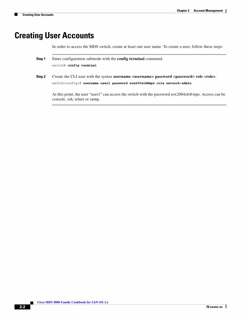
Chapter 2 Account Management Creating User Accounts
Creating User AccountsIn order to access the MDS switch, create at least one user name. To create a user, follow these steps:
Step 1 Enter configuration submode with the config terminal command.
switch# config terminal
Step 2 Create the CLI user with the syntax username <username> password <password> role <role>.
switch(config)# username user1 password sox2004ch@mps role network-admin
At this point, the user “user1” can access the switch with the password sox2004ch@mps. Access can be console, ssh, telnet or snmp.
2-2Cisco MDS 9000 Family Cookbook for SAN-OS 2.x
78-xxxxx-xx

Chapter 2 Account Management Creating a User Role
Creating a User RoleThe MDS switch has two default roles, network-admin and network-operator. Network-admin has write privileges to all parts of the switch, while network-operator has read-only access to the switch. Later, you may want to create a user with write access to only specific areas of the switch (see the example in the “Creating a Role with Device Manager” section on page 2-4).
The MDS switch has two predefined roles:
• Network-admin is the role assigned to an administrator. A network-admin can perform any modification to the MDS platform. There are no restrictions on this user.
• Network-operator is a read-only role. A network-operator can not make modifications to the switch.
Tip • Provide each user with a role that provides them with the minimum abilities needed.
• Use the network-operator role for users who do not need to modify the switch.
• VSAN- based roles allow administrators to have complete control over their VSANs while having read only or no access to other VSANs.
2-3Cisco MDS 9000 Family Cookbook for SAN-OS 2.x
78-xxxxx-xx
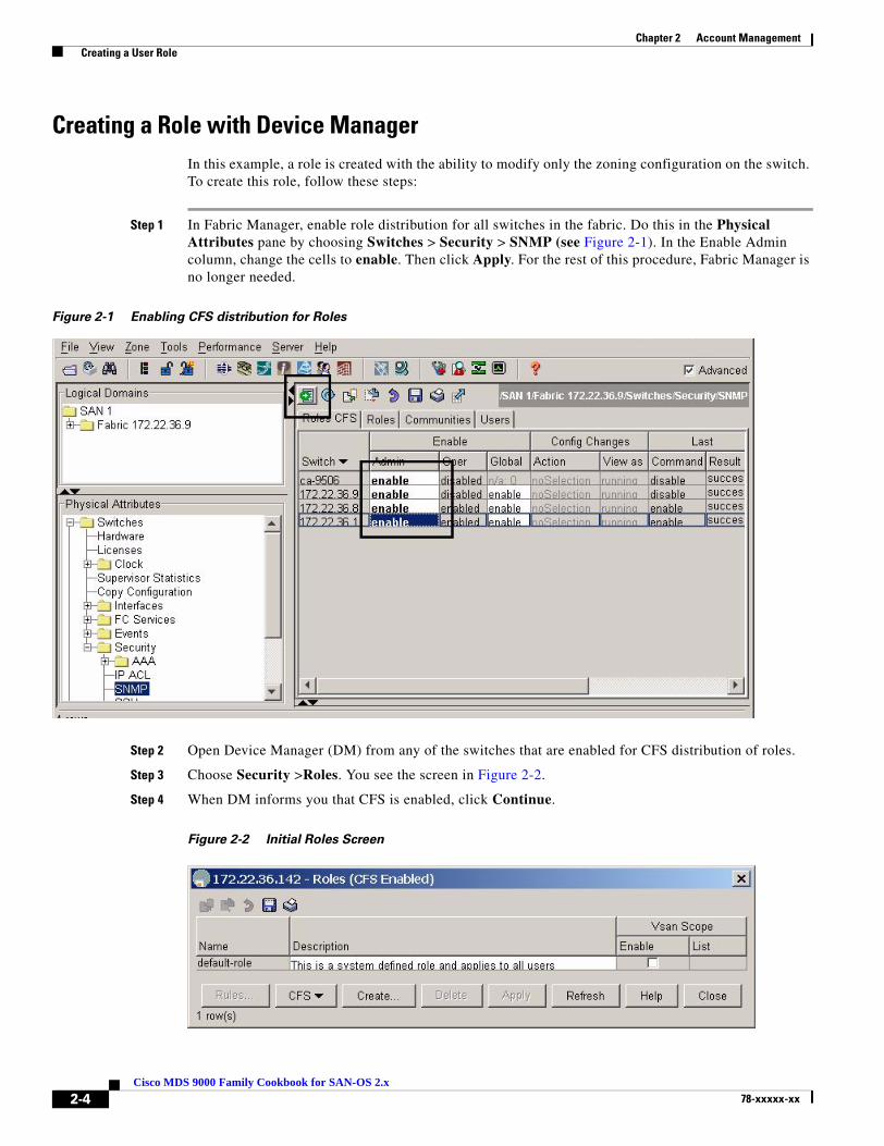
Chapter 2 Account Management Creating a User Role
Creating a Role with Device ManagerIn this example, a role is created with the ability to modify only the zoning configuration on the switch. To create this role, follow these steps:
Step 1 In Fabric Manager, enable role distribution for all switches in the fabric. Do this in the Physical Attributes pane by choosing Switches > Security > SNMP (see Figure 2-1). In the Enable Admin column, change the cells to enable. Then click Apply. For the rest of this procedure, Fabric Manager is no longer needed.
Figure 2-1 Enabling CFS distribution for Roles
Step 2 Open Device Manager (DM) from any of the switches that are enabled for CFS distribution of roles.
Step 3 Choose Security >Roles. You see the screen in Figure 2-2.
Step 4 When DM informs you that CFS is enabled, click Continue.
Figure 2-2 Initial Roles Screen
2-4Cisco MDS 9000 Family Cookbook for SAN-OS 2.x
78-xxxxx-xx

Chapter 2 Account Management Creating a User Role
Step 5 Click Create.
Figure 2-3 Create Common Roles
Step 6 Provide a name and description (no spaces) for the role (see Figure 2-3).
This example does not specify a VSAN scope, but you could optionally create a VSAN scope limiting this specific role to a subset of VSANs. For example, a zoning admin role could be created for zone admins who can only modify VSANs 1-10.
Step 7 Click Rules… to define what this role can and cannot do within the optional VSAN scope by (see Figure 2-3). The Create Common Rules screen shown in Figure 2-4 appears.
Figure 2-4 Create Common Role Rules
Step 8 Choose the CLI Command column to sort the table by CLI command.
Step 9 Check the Show checkbox at the top of the screen to enable show for all commands.
Step 10 Scroll down and check all of the zone, zone-attribute-group and zoneset options.
Step 11 Check copy so that the zoning admin can save the configuration.
Step 12 Click Apply ( see Figure 2-4).
2-5Cisco MDS 9000 Family Cookbook for SAN-OS 2.x
78-xxxxx-xx

Chapter 2 Account Management Creating a User Role
Step 13 Click Create (see Figure 2-5). This saves the role configuration to the CFS pending database. Not until the CFS commit command is executed will this role become part of the running configuration of the switches in the fabric.
Figure 2-5 Create Common Roles
Step 14 Click Close (see Figure 2-5) to return to the original Roles screen (see Figure 2-6). The ZoningAdmin role now exists only in the pending database.
Figure 2-6 Display Roles
Step 15 Commit the changes by expanding CFS (see Figure 2-6) and selecting Commit.
To abort the changes and flush the pending database, expand CFS (see Figure 2-6) and select Abort.
2-6Cisco MDS 9000 Family Cookbook for SAN-OS 2.x
78-xxxxx-xx
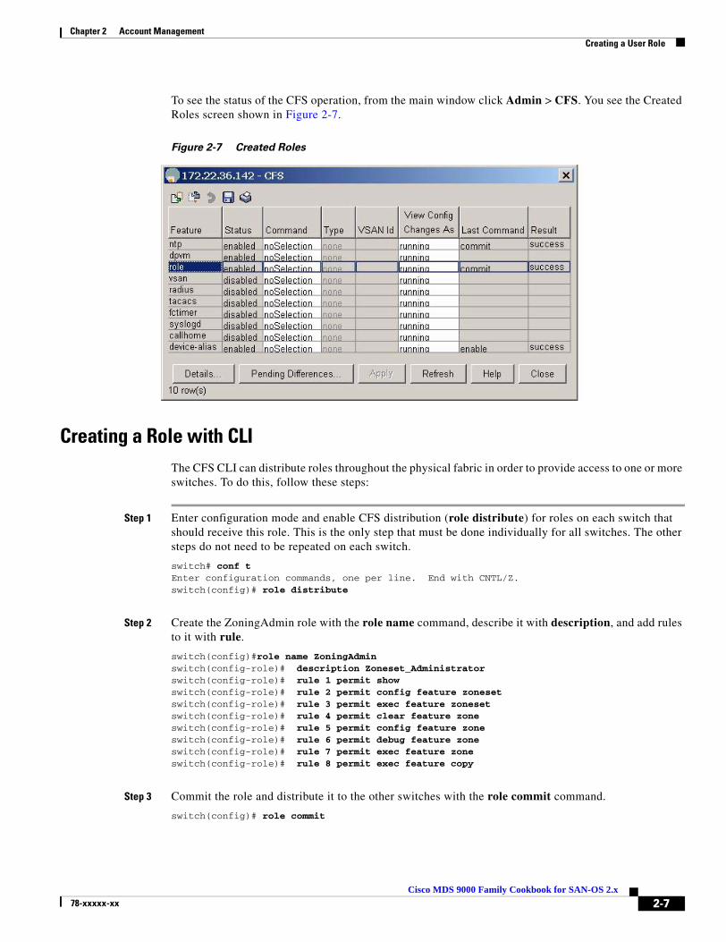
Chapter 2 Account Management Creating a User Role
To see the status of the CFS operation, from the main window click Admin > CFS. You see the Created Roles screen shown in Figure 2-7.
Figure 2-7 Created Roles
Creating a Role with CLIThe CFS CLI can distribute roles throughout the physical fabric in order to provide access to one or more switches. To do this, follow these steps:
Step 1 Enter configuration mode and enable CFS distribution (role distribute) for roles on each switch that should receive this role. This is the only step that must be done individually for all switches. The other steps do not need to be repeated on each switch.
switch# conf tEnter configuration commands, one per line. End with CNTL/Z.switch(config)# role distribute
Step 2 Create the ZoningAdmin role with the role name command, describe it with description, and add rules to it with rule.
switch(config)#role name ZoningAdminswitch(config-role)# description Zoneset_Administratorswitch(config-role)# rule 1 permit showswitch(config-role)# rule 2 permit config feature zonesetswitch(config-role)# rule 3 permit exec feature zonesetswitch(config-role)# rule 4 permit clear feature zoneswitch(config-role)# rule 5 permit config feature zoneswitch(config-role)# rule 6 permit debug feature zoneswitch(config-role)# rule 7 permit exec feature zoneswitch(config-role)# rule 8 permit exec feature copy
Step 3 Commit the role and distribute it to the other switches with the role commit command.
switch(config)# role commit
2-7Cisco MDS 9000 Family Cookbook for SAN-OS 2.x
78-xxxxx-xx

Chapter 2 Account Management Creating a User Role
Step 4 Create the user zoning_user and assign him the new ZoningAdmin role.
switch# config terminalswitch(config)# username zoning_user password g0s0x456 role ZoningAdmin
Step 5 Save the configuration fabric-wide with the copy running-config startup-config fabric command.
switch(config)# copy running-config startup-config fabric[########################################] 100%
2-8Cisco MDS 9000 Family Cookbook for SAN-OS 2.x
78-xxxxx-xx
Chapter 2 Account Management Configuring TACACS+ with Cisco SecureACS
Configuring TACACS+ with Cisco SecureACSCisco’s SecureACS product enhances MDS switch management security and provides centralized authentication, authorization and accounting of users.
Tip We recommend that a tacacs+ server be used for authentication, authorization and accounting.
With TACACS+ implemented, you don’t have to perform password recovery on the MDS switch.
Authentication and Authorization with TACACS+Configuring an MDS switch to use tacacs+ will allow centralized account management of the switch. This centralized management will allow an admin to not have to create and maintain user names and passwords on individual switches. The SecureACS server will provide the authentication to a switch login as well as assigning the role that the user is a member of. A shared secret key is used to provide encryption and authentication between the tacacs client (MDS-9500) and the tacacs server (Cisco SecureACS).
In this example, these assumptions are made:
• The switch’s IP address is 172.22.36.142.
• The tacacs+ server’s IP address is 172.22.36.10.
• The tacacs+ shared secret key is WarEagle.
2-9Cisco MDS 9000 Family Cookbook for SAN-OS 2.x
78-xxxxx-xx

Chapter 2 Account Management Configuring TACACS+ with Cisco SecureACS
Configure SecureACS Server
Before you configure the switch, configure the SecureACS server with Cisco SecureACS by following these steps:
Step 1 Configure SecureACS to allow modification of advanced tacacs settings.
a. On the main screen left pane, choose Interface Configuration. You then see the Interface Configuration screen in Figure 2-8.
Figure 2-8 SecureACS Configure Display
b. Select TACACS+ (Cisco IOS).
c. Check both Advanced TACACS+ Features and Display a window...attributes.
d. Click Submit to save the changes.
2-10Cisco MDS 9000 Family Cookbook for SAN-OS 2.x
78-xxxxx-xx
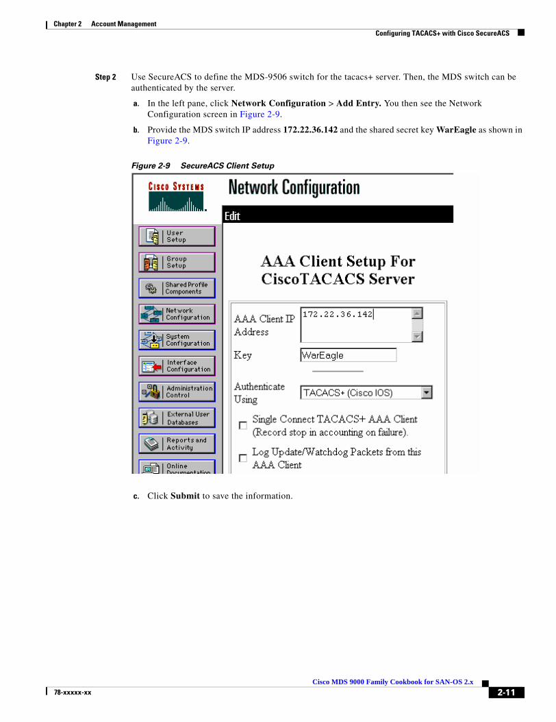
Chapter 2 Account Management Configuring TACACS+ with Cisco SecureACS
Step 2 Use SecureACS to define the MDS-9506 switch for the tacacs+ server. Then, the MDS switch can be authenticated by the server.
a. In the left pane, click Network Configuration > Add Entry. You then see the Network Configuration screen in Figure 2-9.
b. Provide the MDS switch IP address 172.22.36.142 and the shared secret key WarEagle as shown in Figure 2-9.
Figure 2-9 SecureACS Client Setup
c. Click Submit to save the information.
2-11Cisco MDS 9000 Family Cookbook for SAN-OS 2.x
78-xxxxx-xx
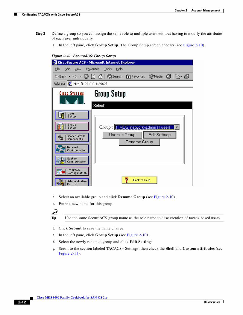
Chapter 2 Account Management Configuring TACACS+ with Cisco SecureACS
Step 3 Define a group so you can assign the same role to multiple users without having to modify the attributes of each user individually.
a. In the left pane, click Group Setup. The Group Setup screen appears (see Figure 2-10).
Figure 2-10 SecureACS: Group Setup
b. Select an available group and click Rename Group (see Figure 2-10).
c. Enter a new name for this group.
Tip Use the same SecureACS group name as the role name to ease creation of tacacs-based users.
d. Click Submit to save the name change.
e. In the left pane, click Group Setup (see Figure 2-10).
f. Select the newly renamed group and click Edit Settings.
g. Scroll to the section labeled TACACS+ Settings, then check the Shell and Custom attributes (see Figure 2-11).
2-12Cisco MDS 9000 Family Cookbook for SAN-OS 2.x
78-xxxxx-xx
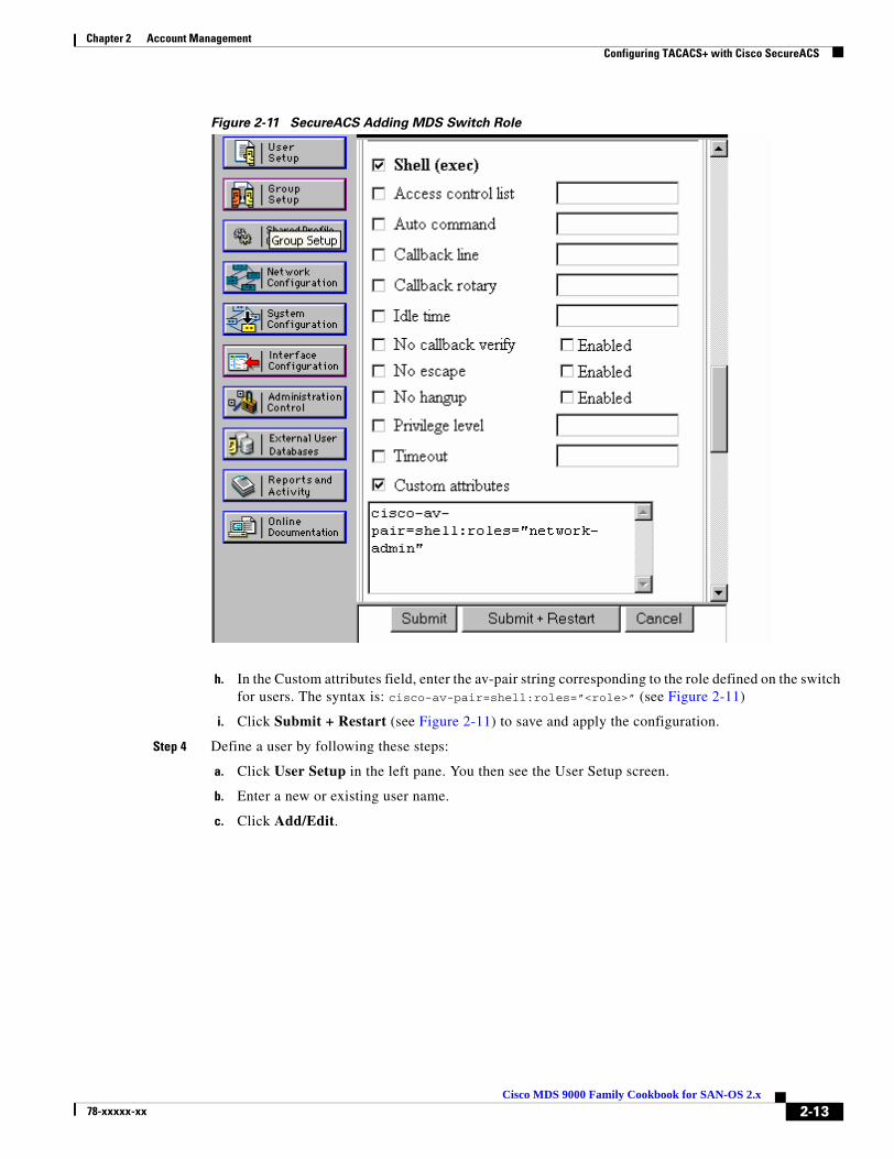
Chapter 2 Account Management Configuring TACACS+ with Cisco SecureACS
Figure 2-11 SecureACS Adding MDS Switch Role
h. In the Custom attributes field, enter the av-pair string corresponding to the role defined on the switch for users. The syntax is: cisco-av-pair=shell:roles=”<role>” (see Figure 2-11)
i. Click Submit + Restart (see Figure 2-11) to save and apply the configuration.
Step 4 Define a user by following these steps:
a. Click User Setup in the left pane. You then see the User Setup screen.
b. Enter a new or existing user name.
c. Click Add/Edit.
2-13Cisco MDS 9000 Family Cookbook for SAN-OS 2.x
78-xxxxx-xx

Chapter 2 Account Management Configuring TACACS+ with Cisco SecureACS
d. Provide the information for the fields Password, Confirm Password and Group to which user is assigned (see Figure 2-12).
Figure 2-12 SecureACS Creating tacacs+ user
Configuring the SecureACS server is complete.Next, configure the MDS switch itself.
Configure TACACS+ on the MDS Switch
Configuring the MDS switch can be done from the either the CLI or SNMP. To configure the switch from the CLI, follow these steps:
Step 1 Enter configuration mode, the enable tacacs+.
ca-9506# conf tEnter configuration commands, one per line. End with CNTL/Z.ca-9506(config)# tacacs+ enable
Step 2 Define the tacacs+ server 172.22.36.10 and the corresponding shared secret key WarEagle.
ca-9506(config)# tacacs-server host 172.22.36.10 key WarEagle
2-14Cisco MDS 9000 Family Cookbook for SAN-OS 2.x
78-xxxxx-xx

Chapter 2 Account Management Configuring TACACS+ with Cisco SecureACS
Step 3 Define a group of authentication servers to use, then add the tacacs+ server to the group.
ca-9506(config)# aaa group server tacacs+ tacacs-group1ca-9506(config-tacacs+)# server 172.22.36.10
Step 4 Define the authentication method for the switch’s telnet/ssh/snmp access.
ca-9506(config)# aaa authentication login default group tacacs-group1
Step 5 Use show commands to display and check the configuration:
ca-9506# show tacacs-server
timeout value:5total number of servers:1
following TACACS+ servers are configured: 172.22.36.10: available on port:49 TACACS+ shared secret:********ca-9506# show aaa authentication default: group tacacs-group1 console: local iscsi: local dhchap: local
ca-9506# show user-accountuser:admin this user account has no expiry date roles:network-admin
user:seth expires on Fri Jun 18 23:59:59 2004 roles:network-adminaccount created through REMOTE authenticationLocal login not possible
Note The user seth is not available locally on the switch and yet is a member of the group/role network-admin. This means seth was authenticated by the tacacs+ server and not by the switch.
Accounting with TACACS+Cisco’s SecureACS server can provide a command history of users and their actions. This information is similar to the that provided by the CLI command show accounting log. However, by placing the information on a remote system, the logs can be independently examined and are available if the switch is inaccessible. This configuration builds upon the configuration defined in Authentication and Authorization with TACACS+, page 2-9.
2-15Cisco MDS 9000 Family Cookbook for SAN-OS 2.x
78-xxxxx-xx
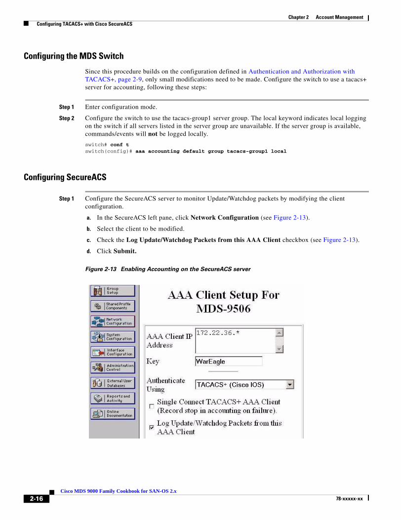
Chapter 2 Account Management Configuring TACACS+ with Cisco SecureACS
Configuring the MDS Switch
Since this procedure builds on the configuration defined in Authentication and Authorization with TACACS+, page 2-9, only small modifications need to be made. Configure the switch to use a tacacs+ server for accounting, following these steps:
Step 1 Enter configuration mode.
Step 2 Configure the switch to use the tacacs-group1 server group. The local keyword indicates local logging on the switch if all servers listed in the server group are unavailable. If the server group is available, commands/events will not be logged locally.
switch# conf tswitch(config)# aaa accounting default group tacacs-group1 local
Configuring SecureACS
Step 1 Configure the SecureACS server to monitor Update/Watchdog packets by modifying the client configuration.
a. In the SecureACS left pane, click Network Configuration (see Figure 2-13).
b. Select the client to be modified.
c. Check the Log Update/Watchdog Packets from this AAA Client checkbox (see Figure 2-13).
d. Click Submit.
Figure 2-13 Enabling Accounting on the SecureACS server
2-16Cisco MDS 9000 Family Cookbook for SAN-OS 2.x
78-xxxxx-xx
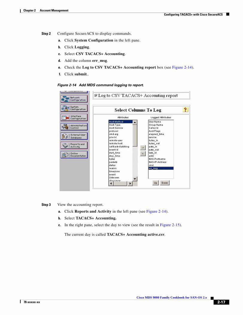
Chapter 2 Account Management Configuring TACACS+ with Cisco SecureACS
Step 2 Configure SecureACS to display commands.
a. Click System Configuration in the left pane.
b. Click Logging.
c. Select CSV TACACS+ Accounting.
d. Add the column err_msg.
e. Check the Log to CSV TACACS+ Accounting report box (see Figure 2-14).
f. Click submit..
Figure 2-14 Add MDS command logging to report.
Step 3 View the accounting report.
a. Click Reports and Activity in the left pane (see Figure 2-14).
b. Select TACACS+ Accounting.
c. In the right pane, select the day to view (see the result in Figure 2-15).
The current day is called TACACS+ Accounting active.csv.
2-17Cisco MDS 9000 Family Cookbook for SAN-OS 2.x
78-xxxxx-xx

Chapter 2 Account Management Configuring TACACS+ with Cisco SecureACS
Figure 2-15 SecureACS Accounting Log
2-18Cisco MDS 9000 Family Cookbook for SAN-OS 2.x
78-xxxxx-xx

Chapter 2 Account Management Providing Password-free Access Using SSH
Providing Password-free Access Using SSHYou can allow switch access with no password from automated scripts or agents. Providing a null password or hard coding the password into the script or agent could be considered a weak security practice. However, using the private/public key infrastructure of SSH maintains a secure environment. SSH uses a private/public key exchange; the switch knows only the public key while the host knows both the public and private keys. Access is only granted if the user comes from a host that knows both the public and private keys
This procedure includes creating the appropriate key on a host, then adding the key to a new read-only (network-operator) user.
Tip Assign password-free logons to either a read-only role like network-operator or to a role with a minimal set of privileges.
Caution Having only the public key does not trigger the switch to grant access. The private key must also be on the host. Treat the private key like a password.
Step 1 Create an SSH RSA1 public/private key on the host.
$ /usr/bin/ssh-keygen -t rsa1Generating public/private rsa1 key pair.Enter file in which to save the key (/users/testuser/.ssh/identity):/users/testuser/.ssh/identity already exists.Overwrite (y/n)? yEnter passphrase (empty for no passphrase):Enter same passphrase again:Your identification has been saved in /users/testuser/.ssh/identity.Your public key has been saved in /users/testuser/.ssh/identity.pub.The key fingerprint is:c2:4d:6d:26:21:9d:79:9b:c3:86:dc:a5:07:d2:62:d4 testuser@host
On the host, the file /users/testuser/.ssh/identity.pub is the ssh public key that is encrypted using the rsa1 algorithm. The contents of this file will be used in the creation of the MDS switch user. In this example, the file looks like this:
$ cat /users/testuser/.ssh/identity.pub1024 35 139198677264732164858153476357747926024656548233745027006381178621992083524037906211714241450436547019604214530354070873624269283640613058470615170649963414635036859628344005142227886318134122126153182906740418449098047827961768214148936752631482459130056603268404256522191410368204629699075809390037814979061 testuser@host
2-19Cisco MDS 9000 Family Cookbook for SAN-OS 2.x
78-xxxxx-xx

Chapter 2 Account Management Providing Password-free Access Using SSH
Step 2 On the switch, create all of the SSH keys, even though in this case the client is using RSA1.
172.22.36.11# conf tEnter configuration commands, one per line. End with CNTL/Z.
172.22.36.11(config)# ssh key rsa1generating rsa1 key(1024 bits).....generated rsa1 key
ca-9506(config)# ssh key dsagenerating dsa key(1024 bits).....generated dsa key
ca-9506(config)# ssh key rsagenerating rsa key(1024 bits).....generated rsa key
Step 3 Enable SSH on the switch.
172.22.36.11(config)# ssh server enable
Step 4 On the switch, create the user, pasting in the contents of the identity.pub file after the SSH key parameter.
172.22.36.11# conf tEnter configuration commands, one per line. End with CNTL/Z.172.22.36.11(config)# username testuser role network-operatorwarning: password for user:testuser not set. S/he cannot login currently172.22.36.11(config)# username testuser sshkey 1024 35 139198677264732164858153476357747926024656548233745027006381178621992083524037906211714241450436547019604214530354070873624269283640613058470615170649963414635036859628344005142227886318134122126153182906740418449098047827961768214148936752631482459130056603268404256522191410368204629699075809390037814979061 [email protected](config)# end
Step 5 Look at the configuration of the user with the show user-account command.
172.22.36.11# show user-account testuseruser: testuser this user account has no expiry date roles:network-operatorno password set. Local login not allowedRemote login through RADIUS/TACACS+ is possible ssh public key: 1024 35 139198677264732164858153476357747926024656548233745027006381178621992083524037906211714241450436547019604214530354070873624269283640613058470615170649963414635036859628344005142227886318134122126153182906740418449098047827961768214148936752631482459130056603268404256522191410368204629699075809390037814979061 testuser@host
Step 6 Test the log in process from the host with the testuser command.
$ ssh [email protected]: Remote host denied X11 forwarding.Cisco Storage Area Networking Operating System (SAN-OS) SoftwareTAC support: http://www.cisco.com/tacCopyright (c) 2002-2004, Cisco Systems, Inc. All rights reserved.The copyrights to certain works contained herein are owned byother third parties and are used and distributed under license.Some parts of this software are covered under the GNU PublicLicense. A copy of the license is available athttp://www.gnu.org/licenses/gpl.html.172.22.36.11#
2-20Cisco MDS 9000 Family Cookbook for SAN-OS 2.x
78-xxxxx-xx

Chapter 2 Account Management Providing Password-free Access Using SSH
If the same user tries logging in from another host without both the private key file (/users/testuser/.ssh/identity) and the public key file (/users/testuser/.ssh/identity), then access to the switch is denied. The fact that the public key has testuser@host included does not tie it to a specific host but does allow an admin to determine from which host it was generated.
Tip A simple way to use this feature is to schedule a nightly backup (using cron for example) for the switch configuration using SSH. The following backup example works as long as the user indicated has the privilege to issue the copy command.
#!/bin/sh#######################################################/usr/local/bin/backup_mds_config.sh
# This is used for a cron entry. No arguments are # allowed in cron.Absolute paths to commands must # be specified to ssh for it to work properly # ssh key exchange must be separately configured # for the account "USER"## Adjust the variables for your host and switch ######################################################
DIR=/mds_configDATE=`date "+%m%d%y_%H%M%S"`SWITCH_NAME=beat_bamaFILE=$SWITCH_NAME"_run_cfg_"$DATEUSER=testuserCOMMAND1="copy running-config startup-config’COMMAND2="show startup-config"
#Copy running to startup-config/usr/local/bin/ssh -l $USER $SWITCH_NAME $COMMAND1#Backup MDS config to local file/usr/local/bin/ssh -l $USER $SWITCH_NAME $COMMAND2 > $DIR/$FILE
Set up cron to execute the script. The cron job must be run by the user specified in the script. Configure the crontab for the user. This example runs at 11:00pm every Sunday.
#Backup MDS config:00 23 * * 0 /usr/local/bin/backup_mds_config.sh > /mds_logs/beat_bama1
2-21Cisco MDS 9000 Family Cookbook for SAN-OS 2.x
78-xxxxx-xx

Chapter 2 Account Management Providing Password-free Access Using SSH
2-22Cisco MDS 9000 Family Cookbook for SAN-OS 2.x
78-xxxxx-xx
Cisco MDS 9078-xxxxx-xx
C H A P T E R 3
Physical InterfacesThe MDS switch is a multi-protocol switch. In this section various protocol options are used to configure the FibreChannel (FC) and Gigabit Ethernet ports.
The recipes below show how to configure various parameters and modes for a physical port on the MDS.
Configuring FC ports
Port DescriptionA port description provides a plain text description for the interface of a port on a switch. In this example, the fibre channel interface fc 1/1 is given the description “storage array 17 port 1.”
switch# conf tEnter configuration commands, one per line. End with CNTL/Z.switch(config)# interface fc 1/1switch(config-if)# switchport description “storage array 17 port 1”switch(config-if)# endswitch#
Port SpeedThis example sets the port speed for fc 1/1 to either 1Gb, 2Gb or an automatically negotiated speed.
Note A port can be set to only one speed at a time. The default is auto-negotiate.
switch# conf tEnter configuration commands, one per line. End with CNTL/Z.switch(config)# interface fc 1/1switch(config-if)# switchport speed 1000 <- port speed set to 1 GBswitch(config-if)# switchport speed 2000 <- port speed set to 2 GBswitch(config-if)# switchport speed auto <- port speed set to auto negotiateswitch(config-if)# ^Zswitch#
3-100 Family Cookbook for SAN-OS 2.x

Chapter 3 Physical Interfaces Configuring FC ports
Port Mode Auto
Note A FC ports can be set to only one port mode at a time. The default is auto on the 16 port line cards and FX on the 32 port line cards.
Setting port mode to auto allows the port to negotiate to either F port mode, FL port mode or E port mode. It can not negotiate to ST port mode, SD port mode or TL port mode.
In this example, fc 1/1 is set to auto port mode. This is the default setting for all ports on a 16 port line card.
switch# conf tEnter configuration commands, one per line. End with CNTL/Z.switch(config)# interface fc 1/1switch(config-if)# switchport mode autoswitch(config-if)# endswitch#
Port Mode ESetting port mode to E restricts the port to operating as an E port; the port can be either trunking or non-trunking depending on the trunking port mode. E port mode is used when the port function is at one end of an ISL. In this example, fc 1/1 is set to E port mode.
switch# conf tEnter configuration commands, one per line. End with CNTL/Z.switch(config)# interface fc 1/1switch(config-if)# switchport mode Eswitch(config-if)# end
Port Mode FSetting port mode to F restricts the port to operating as an F port. F port mode is used for end devices that can only communicate in point-to-point mode or to a switch. In this example, fc 1/1 is set to F port mode.
switch# conf tEnter configuration commands, one per line. End with CNTL/Z.switch(config)# interface fc 1/1switch(config-if)# switchport mode F switch(config-if)# endswitch#
Port Mode FLSetting port mode to FL restricts the port to operating as an FL port. FL port mode is used for end devices that can only communicate as a public loop device. In this example, fc 1/1 is set to FL port mode.
switch# conf tEnter configuration commands, one per line. End with CNTL/Z.switch(config)# interface fc 1/1switch(config-if)# switchport mode FL switch(config-if)# endswitch#
3-2Cisco MDS 9000 Family Cookbook for SAN-OS 2.x
78-xxxxx-xx

Chapter 3 Physical Interfaces Configuring FC ports
Port Mode FxSetting port mode to Fx restricts the port to operating as either an F or FL port. Fx port mode is used exclusively for end devices and prevents a port from auto-negotiating to an E port. In this example, fc 1/1 is set to Fx port mode.
switch# conf tEnter configuration commands, one per line. End with CNTL/Z.switch(config)# interface fc 1/1switch(config-if)# switchport mode Fx switch(config-if)# endswitch#
Port Mode SDSetting port mode to SD configures the port as the span destination (SD) port of a span session. This is used in conjunction with the PAA to span a port and obtain FC traces without a FC analyzer. In this example, fc 1/1 is set to SD port mode.
switch# conf tEnter configuration commands, one per line. End with CNTL/Z.switch(config)# interface fc 1/1switch(config-if)# switchport mode SD switch(config-if)# end
Port mode STSetting port mode to ST configures the port as the span tunnel (ST) port of a remote span session. This is used to set up a remote SPAN session to a remote switch in which a PAA or protocol analyzer is connected. In this example, fc 1/1 is set to ST port mode.
switch# conf tEnter configuration commands, one per line. End with CNTL/Z.switch(config)# interface fc 1/1switch(config-if)# switchport mode ST switch(config-if)# endswitch#
Port mode TLSetting port mode to TL restricts the port to operating as a TL port. TL port mode is used exclusively for end devices that can only communicate as a private loop device. In this example, fc 1/1 is set to TLport mode.
switch# conf tEnter configuration commands, one per line. End with CNTL/Z.switch(config)# interface fc 1/1switch(config-if)# switchport mode TL switch(config-if)# endswitch#
3-3Cisco MDS 9000 Family Cookbook for SAN-OS 2.x
78-xxxxx-xx

Chapter 3 Physical Interfaces Configuring FC ports
Configuring Trunking E portsA trunking port is used to carry VSAN-enabled frames between switches. The section below shows various configuration options for a trunking port.
Note These same commands apply to port channels. Specify the port channel interface int port-channel 1 rather than an individual link interface fc 1/1.
Trunk Port Mode
This example sets fc 1/1 trunk port mode to auto, on and off. Default mode is auto. One end of an ISL should be set to on when connected between two MDS switches, while the other end can be either on or auto. It needs to be off when talking to non-MDS switches.
switch# conf tEnter configuration commands, one per line. End with CNTL/Z.switch(config)# interface fc 1/1switch(config-if)# switchport trunk mode auto <− auto negotiates trunk port modeswitch(config-if)# switchport trunk mode on <− sets trunk port mode to onswitch(config-if)# switchport trunk mode off <− sets trunk port mode to offswitch(config-if)# ^Zswitch#
Configuring Trunk Ports to Filter Specific VSANs
This example configures allowed VSAN traffic through the interface fc 1/1. The “all” keyword allows all VSAN traffic to go through the port. “Add 2” adds VSAN 2 to the list of VSANs allowed through the port. “Add 2-4” adds VSANs 2 through 4 to the list of VSANs allowed through the port. Default mode is to allow all VSAN traffic to pass through the port.
switch# conf tEnter configuration commands, one per line. End with CNTL/Z.switch(config)# interface fc 1/1switch(config-if)# switchport trunk allowed vsan all <− all VSAN trafficswitch(config-if)# switchport trunk allowed vsan add 2 <− only VSAN 2 trafficswitch(config-if)# switchport trunk allowed vsan add 2-4 <− VSAN 2 to 4 trafficswitch(config-if)# ^Zswitch#
Enabling Port BeaconingThis example causes the LEDs below port fc 1/1 to start flashing. This is useful in identifying a port for physical cabling or trouble shooting.
switch# conf tEnter configuration commands, one per line. End with CNTL/Z.switch(config)# interface fc 1/1switch(config-if)# switchport beaconswitch(config-if)# end
3-4Cisco MDS 9000 Family Cookbook for SAN-OS 2.x
78-xxxxx-xx
Chapter 3 Physical Interfaces Configuring Gigabit Ethernet Ports
Configuring Gigabit Ethernet Ports
Configuring VRRPVirtual Router Redundancy Protocol (VRRP) allows two gigabit Ethernet interfaces to provide failover capability for an IP address. The two interfaces form an active/passive or master/backup state in which one interface services requests for the shared IP address, while the other remains in a backup or standby state. It is ideal for providing port level redundancy in iSCSI configurations. A gigabit Ethernet port can still have its own IP address while partaking in a VRRP configuration.
A VRRP session has an ID assigned to it for which the two interfaces will communicate to identify its peer. The same ID must be used on both switches. The procedure for having both members of the VRRP pair on the same switch would be the same as if the two members were on different switches.
Note To have one interface become the master interface whenever it is online(preemption) set the gigabit Ethernet interface to have the same IP address as the VRRP IP address.
In this example, the configuration is as follows:
• VRRP ID: 1
• VRRP IP address: 192.168.1.40
• Switch 1:Interface gige3/3 (192.168.1.20)
• Switch 2:Interface gige4/1 (192.168.1.30)
To configure VRRP, follow these steps:
Step 1 Configure IP addresses on the two GigE interfaces.
Switch1# config terminalEnter configuration commands, one per line. End with CNTL/Z.Switch1(config)# interface gigabitethernet 3/3Switch1(config-if)# ip address 192.168.1.20 255.255.255.0Switch1(config-if)# no shut
Switch2# config terminalEnter configuration commands, one per line. End with CNTL/Z.Switch2(config)# interface gigabitethernet 4/1Switch2(config-if)# ip address 192.168.1.30 255.255.255.0Switch2(config-if)# no shut
At this point, it is a good idea to verify that a host on the local subnet can ping both IP addresses (192.168.1.20 and 192.168.1.30). Alternatively, the ‘ips measure-rtt’ command can be used to ping one GigE port from the other.
Switch1# ips measure-rtt 192.168.1.30 interface gigabitethernet 3/3Round trip time is 172 micro seconds (0.17 milli seconds)
3-5Cisco MDS 9000 Family Cookbook for SAN-OS 2.x
78-xxxxx-xx

Chapter 3 Physical Interfaces Configuring Gigabit Ethernet Ports
Step 2 Configure the VRRP session on both switches using the VRRP id (1).
Switch1# conf tEnter configuration commands, one per line. End with CNTL/Z.Switch1(config)# interface gigabitethernet 3/3Switch1(config-if)# vrrp 1Switch1(config-if-vrrp)# address 192.168.1.40Switch1(config-if-vrrp)# no shutSwitch1(config-if-vrrp)# end
Switch2# conf tEnter configuration commands, one per line. End with CNTL/Z.Switch2(config)# interface gigabitethernet 4/1Switch2(config-if)# vrrp 1Switch2(config-if-vrrp)# address 192.168.1.40Switch2(config-if-vrrp)# no shutSwitch2(config-if-vrrp)# end
Step 3 Verify that the VRRP session is up and determine which interface has become the master with the show vrrp vr command.
Switch2# show vrrp vr 1 Interface VR Status------------------------------------------------------- GigabitEthernet3/3 1 backup
switch1# show vrrp vr 1 interface gig3/3 statusvr id 1 statusMAC address 00:00:5e:00:01:01Operational state: masterUp time 8 sec
View the configuration with the show vrrp vr command.
Switch1# show vrrp vr 1 interface gigabitethernet 3/3 configurationvr id 1 configurationadmin state uppriority 100associated ip: 192.168.1.40no authenticationadvertisement-interval 1preempt noprotocol IP
3-6Cisco MDS 9000 Family Cookbook for SAN-OS 2.x
78-xxxxx-xx
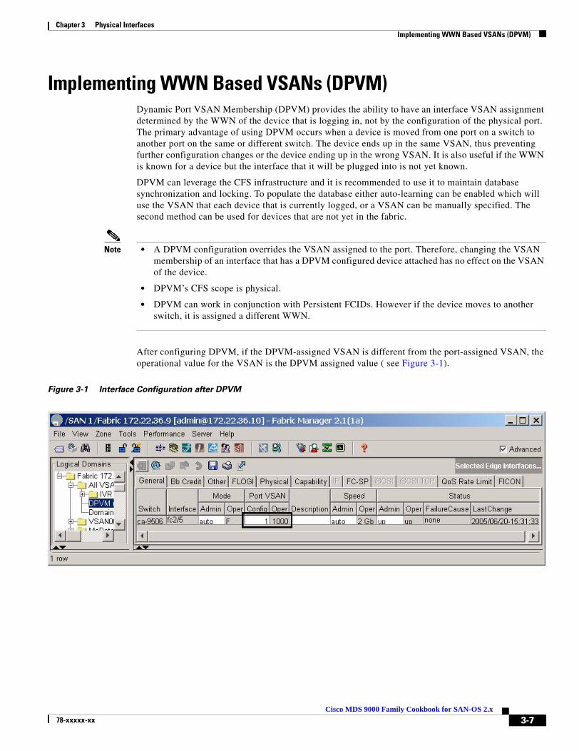
Chapter 3 Physical Interfaces Implementing WWN Based VSANs (DPVM)
Implementing WWN Based VSANs (DPVM)Dynamic Port VSAN Membership (DPVM) provides the ability to have an interface VSAN assignment determined by the WWN of the device that is logging in, not by the configuration of the physical port. The primary advantage of using DPVM occurs when a device is moved from one port on a switch to another port on the same or different switch. The device ends up in the same VSAN, thus preventing further configuration changes or the device ending up in the wrong VSAN. It is also useful if the WWN is known for a device but the interface that it will be plugged into is not yet known.
DPVM can leverage the CFS infrastructure and it is recommended to use it to maintain database synchronization and locking. To populate the database either auto-learning can be enabled which will use the VSAN that each device that is currently logged, or a VSAN can be manually specified. The second method can be used for devices that are not yet in the fabric.
Note • A DPVM configuration overrides the VSAN assigned to the port. Therefore, changing the VSAN membership of an interface that has a DPVM configured device attached has no effect on the VSAN of the device.
• DPVM’s CFS scope is physical.
• DPVM can work in conjunction with Persistent FCIDs. However if the device moves to another switch, it is assigned a different WWN.
After configuring DPVM, if the DPVM-assigned VSAN is different from the port-assigned VSAN, the operational value for the VSAN is the DPVM assigned value ( see Figure 3-1).
Figure 3-1 Interface Configuration after DPVM
3-7Cisco MDS 9000 Family Cookbook for SAN-OS 2.x
78-xxxxx-xx

Chapter 3 Physical Interfaces Implementing WWN Based VSANs (DPVM)
The CLI is different. In the CLI, the operational VSAN assignment is displayed in the Port vsan field. The configured VSAN displays the VSAN that the port would belong to if DPVM was not configured.
switch# show int fc2/5fc2/5 is up Hardware is Fibre Channel, SFP is short wave laser w/o OFC (SN) Port WWN is 20:45:00:0c:85:e9:d2:c0 Admin port mode is auto, trunk mode is on Port mode is F, FCID is 0xef0008 Configured Port vsan is 1 Port vsan is 1000 Speed is 2 Gbps Transmit B2B Credit is 7 Receive B2B Credit is 16 Receive data field Size is 2112
Enable DVM with either the CLI or Fabric Manager before any actual configuration activities take place. Use the CLI command dpvm enable in configure mode to do this.
switch# conf terminalEnter configuration commands, one per line. End with CNTL/Z.switch(config)# dpvm enable
Accomplish the same task in Fabric Manager by following these steps:
Step 1 From Logical Domains, choose All VSANs, > DPVM.
Step 2 Click the Control tab.
Step 3 Set the command field to enable and click Apply Changes (see Figure 3-2).
Figure 3-2 Enabling DPVM with Fabric Manager
After enabling DPVM, proceed to either “Adding Existing Devices to DPVM” on page 9 or “Adding New Devices to DPVM” on page 11 for the rest of the recipe.
3-8Cisco MDS 9000 Family Cookbook for SAN-OS 2.x
78-xxxxx-xx
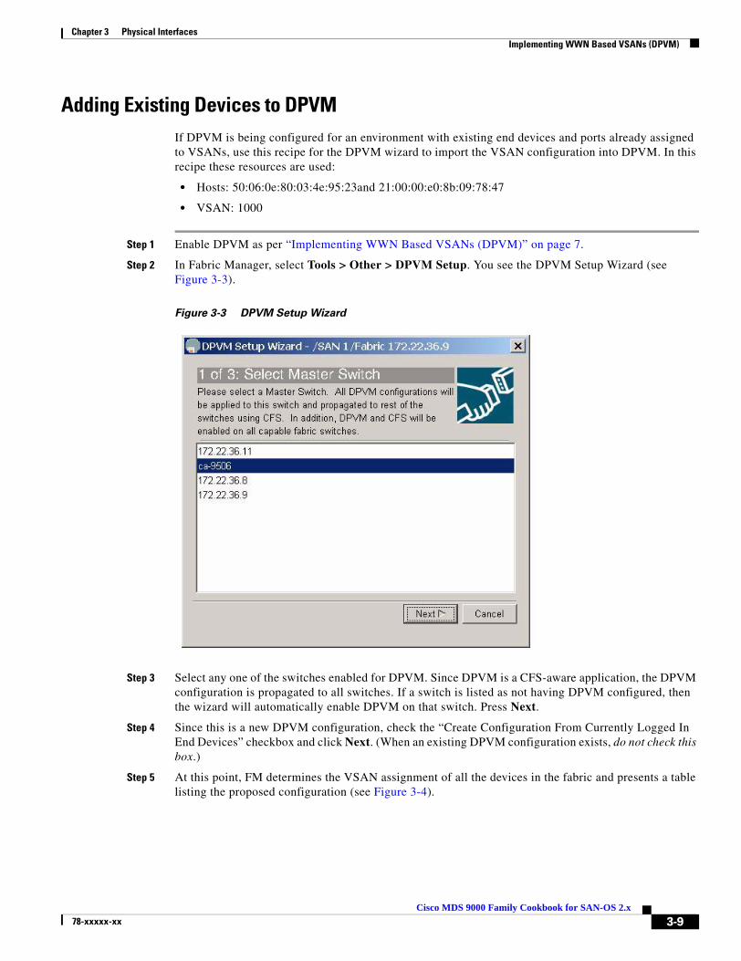
Chapter 3 Physical Interfaces Implementing WWN Based VSANs (DPVM)
Adding Existing Devices to DPVMIf DPVM is being configured for an environment with existing end devices and ports already assigned to VSANs, use this recipe for the DPVM wizard to import the VSAN configuration into DPVM. In this recipe these resources are used:
• Hosts: 50:06:0e:80:03:4e:95:23and 21:00:00:e0:8b:09:78:47
• VSAN: 1000
Step 1 Enable DPVM as per “Implementing WWN Based VSANs (DPVM)” on page 7.
Step 2 In Fabric Manager, select Tools > Other > DPVM Setup. You see the DPVM Setup Wizard (see Figure 3-3).
Figure 3-3 DPVM Setup Wizard
Step 3 Select any one of the switches enabled for DPVM. Since DPVM is a CFS-aware application, the DPVM configuration is propagated to all switches. If a switch is listed as not having DPVM configured, then the wizard will automatically enable DPVM on that switch. Press Next.
Step 4 Since this is a new DPVM configuration, check the “Create Configuration From Currently Logged In End Devices” checkbox and click Next. (When an existing DPVM configuration exists, do not check this box.)
Step 5 At this point, FM determines the VSAN assignment of all the devices in the fabric and presents a table listing the proposed configuration (see Figure 3-4).
3-9Cisco MDS 9000 Family Cookbook for SAN-OS 2.x
78-xxxxx-xx

Chapter 3 Physical Interfaces Implementing WWN Based VSANs (DPVM)
Figure 3-4 Proposed DPVM Configuration
a. If additional entries are desired, click Insert... and provide a WWN and VSAN.
b. If an above entry should be deleted, select the row to be removed and click Delete.
Step 6 Click Finish which will CFS commit the action.
Step 7 To view the DPVM configuration in Fabric Manager, in the Logical Domains pane select the Fabric to view and click All VSANs > DPVM.
Step 8 Choose the CFS tab, which activates the other tabs, then choose the Active Database tab. The active databse screen is shown in Figure 3-5.
3-10Cisco MDS 9000 Family Cookbook for SAN-OS 2.x
78-xxxxx-xx
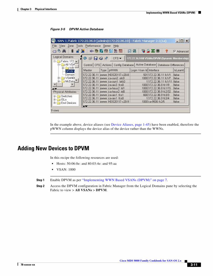
Chapter 3 Physical Interfaces Implementing WWN Based VSANs (DPVM)
Figure 3-5 DPVM Active Database
In the example above, device aliases (see Device Aliases, page 1-45) have been enabled, therefore the pWWN column displays the device alias of the device rather than the WWNs.
Adding New Devices to DPVMIn this recipe the following resources are used:
• Hosts: 50:06:0e: and 80:03:4e: and 95:aa
• VSAN: 1000
Step 1 Enable DPVM as per “Implementing WWN Based VSANs (DPVM)” on page 7.
Step 2 Access the DPVM configuration in Fabric Manager from the Logical Domains pane by selecting the Fabric to view > All VSANs > DPVM.
3-11Cisco MDS 9000 Family Cookbook for SAN-OS 2.x
78-xxxxx-xx

Chapter 3 Physical Interfaces Implementing WWN Based VSANs (DPVM)
Step 3 Click the CFS tab, which activates the other CFS tabs, then choose the Config Database tab. You see the DVPM Config Database screen as shown in Figure 3-6.
Figure 3-6 DPVM Config Database
Step 4 Click the Create Row... icon (located above the CFS tab). The screen in Figure 3-7appears.
Figure 3-7 Creating the DPVM entry.
Step 5 Either select a device from the list or type the pWWN.
Step 6 Select the VSAN to be assigned.
Step 7 Click Create.
Step 8 When all entries have been created, click Close.
In this example, device aliases have been configured (see Device Aliases, page 1-45), therefore devices aliases are displayed instead of the WWNs.
Next, activate the new entry.
3-12Cisco MDS 9000 Family Cookbook for SAN-OS 2.x
78-xxxxx-xx

Chapter 3 Physical Interfaces Implementing WWN Based VSANs (DPVM)
Step 9 Choose the Actions tab.
Step 10 Change the action to activate and click the green Apply Changes icon. Using the activate action ensures that a device currently logged into the fabric does not get accidentally moved into another VSAN, disrupting I/O.
To determine which device is causing a CFS commit to fail, see the section DPVM Conflicting Entries, page 3-14. If the commit ignores this safety check, use the activate force action.
At this point the config and active databases are different. Since DPVM is CFS-enabled, a CFS commit is still required.
Step 11 To commit the changes, click CFS > Commit. If the commit succeeds, you see the message “CFS(dpvm):Committed.”
At this point, the active database contains the new entry.
Modify the VSAN Assignment of a DPVM Entry
In this recipe the VSAN assignment of a device will be changed. These resources are used in the example:
• PWWN: 50:06:0e:80:03:4e:95:33
• Old VSAN: 501
• New VSAN: 1000
Step 1 To access the DPVM configuration in Fabric Manager, in the Logical Domains pane select the fabric to view > All VSANs > DPVM.
Step 2 Click the CFS tab to activate the other tabs, then select the Config Database tab (see Figure 3-8).
Figure 3-8 DPVM Config Database
3-13Cisco MDS 9000 Family Cookbook for SAN-OS 2.x
78-xxxxx-xx

Chapter 3 Physical Interfaces Implementing WWN Based VSANs (DPVM)
Step 3 Select the cell corresponding to the Login VSAN Id to be modified, then enter the new VSAN ID (1000). See Figure 3-9.
Figure 3-9 Modify VSAN Id and Apply Changes
Step 4 Click Apply Changes (see Figure 3-9).
Now activate the change by following these steps:
Step 5 Choose the Actions tab.
Step 6 Change the Action to activate and click the green Apply Changes icon.
Using the activate action ensures that a device currently logged into the fabric is not accidentally moved into another VSAN, thereby disrupting I/O.
To determine which device causes CFS commit to fail, see the sectionDPVM Conflicting Entries, page 3-14. If the commit ignores this safety check, use the activate force action.
At this point the config and active databases are different. Since DPVM is CFS-enabled, a CFS commit is still required.
Step 7 To commit the changes click CFS > Commit. If the commit succeeds, you see the message “CFS(dpvm):Committed..”
At this point, the active database contains the new entry.
DPVM Conflicting Entries
When a DPVM configuration change is commited with a device already logged into the fabric, a warning may be displayed (see Figure 3-10). The message is issued because erforming a DPVM commit under these circumstances would change the device VSAN assignment and potentially cause an I/O disruption. If one of the switches cannot successfully update its configuration, then none of the switches will do it. Resolve the error, then reactivate and commit DPVM.
3-14Cisco MDS 9000 Family Cookbook for SAN-OS 2.x
78-xxxxx-xx
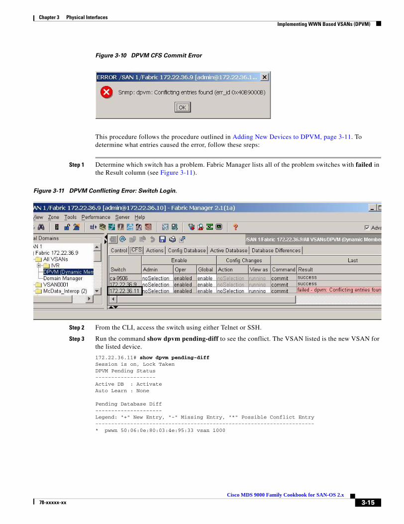
Chapter 3 Physical Interfaces Implementing WWN Based VSANs (DPVM)
Figure 3-10 DPVM CFS Commit Error
This procedure follows the procedure outlined in Adding New Devices to DPVM, page 3-11. To determine what entries caused the error, follow these sreps:
Step 1 Determine which switch has a problem. Fabric Manager lists all of the problem switches with failed in the Result column (see Figure 3-11).
Figure 3-11 DPVM Conflicting Error: Switch Login.
Step 2 From the CLI, access the switch using either Telnet or SSH.
Step 3 Run the command show dpvm pending-diff to see the conflict. The VSAN listed is the new VSAN for the listed device.
172.22.36.11# show dpvm pending-diffSession is on, Lock TakenDPVM Pending Status-------------------Active DB : ActivateAuto Learn : None
Pending Database Diff---------------------Legend: "+" New Entry, "-" Missing Entry, "*" Possible Conflict Entry---------------------------------------------------------------------* pwwn 50:06:0e:80:03:4e:95:33 vsan 1000
3-15Cisco MDS 9000 Family Cookbook for SAN-OS 2.x
78-xxxxx-xx

Chapter 3 Physical Interfaces Implementing WWN Based VSANs (DPVM)
Step 4 Use Fabric Manager to determine the physical location of this device.
a. In the Physical Attributes pane, choose the End Devices folder.
b. Click the WAN heading to sort by pWWN (see Figure 3-12).
Figure 3-12 PWWNs location in the fabric
Step 5 If the port(s) can be safely moved to a new VSAN, select the action force activate. If the port can not be moved safely, remove the conflicting entry from the config database.
DPVM with the CLIDPVM can be manipulated with the CLI as well as with Fabric Manager. Both have the same underlying CFS infrastructure. To enable DPVM from the CLI, use the dpvm enable command.
ca-9506# config terminalEnter configuration commands, one per line. End with CNTL/Z.ca-9506(config)# dpvm enable
Adding Existing Devices to DPVM
To add existing devices that are already logged into the fabric, use the procedure outlined in the section Adding Existing Devices to DPVM, page 3-9.
3-16Cisco MDS 9000 Family Cookbook for SAN-OS 2.x
78-xxxxx-xx

Chapter 3 Physical Interfaces Implementing WWN Based VSANs (DPVM)
Adding New Devices to DPVM
In this recipe, a new device is entered into the DPVM database and configured. These resources are used in the example:
• Hosts: 50:06:0e:and 80:03:4e:and 95:cc
• VSAN: 1000
To enter a new device into the DPVM database and configure it, follow these steps:
Step 1 After logging into the switch enter config mode and the DPVM database.
ca-9506# config terminalEnter configuration commands, one per line. End with CNTL/Z.ca-9506(config)# dpvm databaseca-9506(config-dpvm-db)#
Step 2 Enter the pWWN and the VSAN:
ca-9506(config-dpvm-db)# pwwn 50:06:0e:80:03:4e:95:cc vsan 1000
Step 3 Activate the changes from the current CLI prompt or the previous prompt (enter exit to see it) with the command dpvm activate.
ca-9506(config-dpvm-db)#dpvm activate
Step 4 Prior to committing the changes, look at them with the show dpvm pending-diff command. Look for conflicting devices that may cause the CFS commit to fail.
Note • The “+” represents devices that are being added to the database.
• The “-” represents devices that are being removed from the database.
• The “*” represents devices that are being modified in the database, including those that are currently logged into the fabric and are changing VSAN assignment.
The do keyword is required for exec commands in config mode.
ca-9506(config)# do show dpvm pending-diffSession is on, Lock TakenDPVM Pending Status-------------------Active DB : ActivateAuto Learn : None
Pending Database Diff---------------------Legend: "+" New Entry, "-" Missing Entry, "*" Possible Conflict Entry---------------------------------------------------------------------+ pwwn 50:06:0e:80:03:4e:95:cc vsan 1000
Step 5 Commit the changes with the dpvm commit command.
ca-9506(config)#dpvm commit
3-17Cisco MDS 9000 Family Cookbook for SAN-OS 2.x
78-xxxxx-xx
Chapter 3 Physical Interfaces Implementing WWN Based VSANs (DPVM)
Modify the VSAN Assignment of a DPVM Entry
This procedure is the same as Adding New Devices to DPVM, page 3-17. However, if the device being reassigned to a new VSAN is currently logged into the fabric, use the dpvm activate force command instead of dpvm activate.
3-18Cisco MDS 9000 Family Cookbook for SAN-OS 2.x
78-xxxxx-xx

Cisco MDS 9078-xxxxx-xx
C H A P T E R 4
Logical InterfacesPort ChannelsPort channels aggregate multiple FC or FCIP links into a single, higher speed, fault tolerant FC or FCIP ISL.A port channel has the same configuration options as a single link FC or FCIP ISL. However, building, modifying and reducing port channels is different than working with a single link FC or FCIP ISL. This section discusses these differing port channel operations.
Tip • A port channel should use interfaces on multiple line cards to protect the port channel against line card failure.
• The same channel group number should be used on both ends of a port channel. This aids troubleshooting and identifying the corresponding channel group on the other switch.
• A port channel, like all other interfaces, can have a description. Use the description field to specify exactly where the port channel goes.
• Port channels can use any port on the switch and connect to any other port on a switch.
• Set the initial VSAN Allowed List prior to bringing up the port channel. This prevents VSANs from merging during the initial startup.
Quiesce a Port Channel or ISL LinkIn SAN-OS version 1.3 the quiesce command existed to explicitly inactivate an ISL or a port channel member so that the link could be hitlessly shut down or removed from the port channel. In SAN-OS 2.X, this is default behavior when a shut command is issued to either an ISL or a port channel member. Therefore, the individual quiesce command was obsoleted.
4-100 Family Cookbook for SAN-OS 2.x
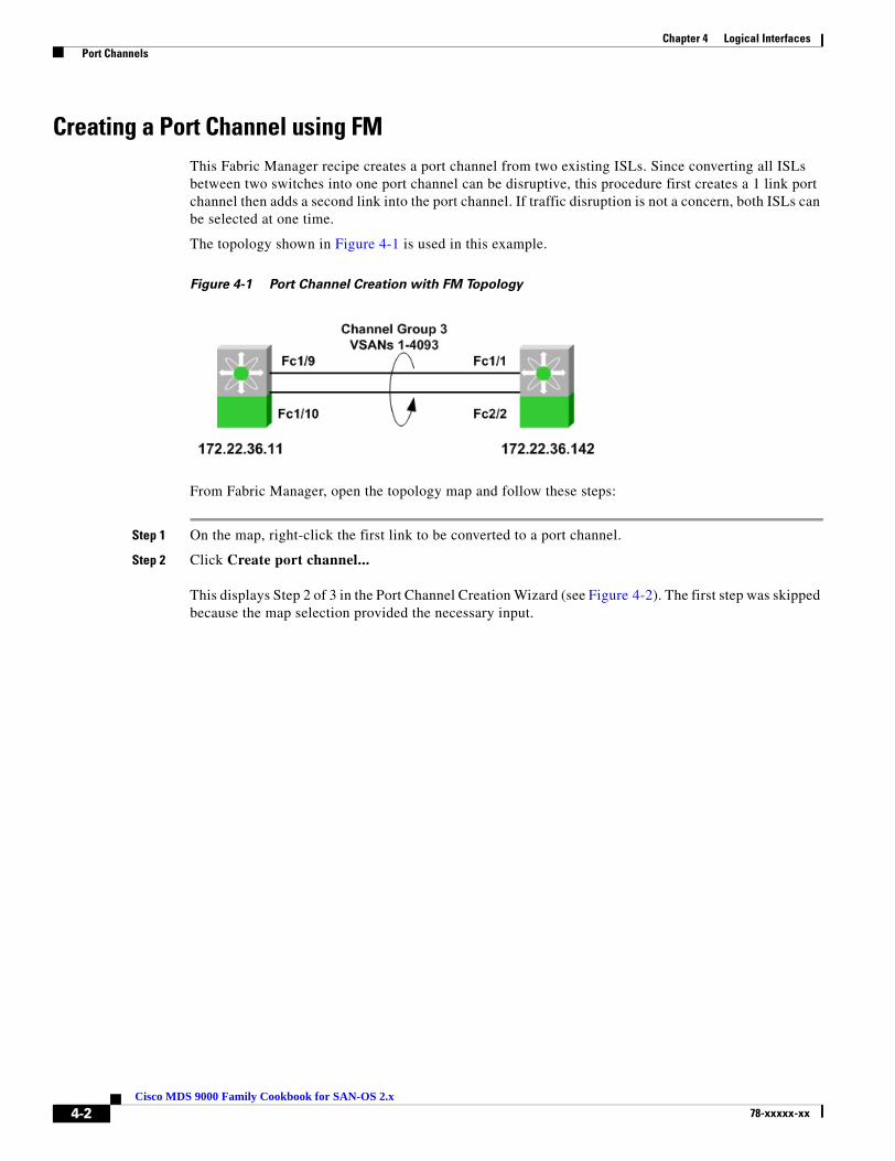
Chapter 4 Logical Interfaces Port Channels
Creating a Port Channel using FMThis Fabric Manager recipe creates a port channel from two existing ISLs. Since converting all ISLs between two switches into one port channel can be disruptive, this procedure first creates a 1 link port channel then adds a second link into the port channel. If traffic disruption is not a concern, both ISLs can be selected at one time.
The topology shown in Figure 4-1 is used in this example.
Figure 4-1 Port Channel Creation with FM Topology
From Fabric Manager, open the topology map and follow these steps:
Step 1 On the map, right-click the first link to be converted to a port channel.
Step 2 Click Create port channel...
This displays Step 2 of 3 in the Port Channel Creation Wizard (see Figure 4-2). The first step was skipped because the map selection provided the necessary input.
4-2Cisco MDS 9000 Family Cookbook for SAN-OS 2.x
78-xxxxx-xx

Chapter 4 Logical Interfaces Port Channels
Figure 4-2 Create Port Channel Wizard
The link you selected from the map appears in the Selected column while any other available or candidate links appear in the Available column. Since this port channel will be created one link at a time, do not move both links into the Selected column.
Step 3 If you are creating a FCIP-based port channel in which the FCIP tunnels have write acceleration (Enabling FCIP Write Acceleration, page 8-25) enabled, then check the “Dynamically form Port Channel Group from selected ISLs” checkbox.
Step 4 Click Next.
4-3Cisco MDS 9000 Family Cookbook for SAN-OS 2.x
78-xxxxx-xx

Chapter 4 Logical Interfaces Port Channels
Figure 4-3 Port Channel Wizard screen 3
The Channel ID (or Channel Group), the descriptions and the Port Channel attributes are displayed on this screen.
Step 5 Modify any of the fields (see Figure 4-3). If the VSAN list needs to be modified to either add or remove VSANs, do this now.
Step 6 Click Finish.
Step 7 A warning is displayed concerning converting ISLs into Port Channels (see Figure 4-4). Since we are only converting one ISL into a Port Channel, the other untouched ISL continues to carry traffic. (FSPF will load balance around this link.) Click Yes to continue.
Figure 4-4 Port Channel Creation Warning
On the Fabric Manager map, the link selected to become a Port Channel momentarily goes down (represented by a red X) then comes back up as a thicker line.
Step 8 On the map, right-click the remaining port channel.
Step 9 Click Edit...
Step 10 Move the remaining ISL (fc1/1 - fc1/9) into the Selected column. You see the screen in Figure 4-2 again.
4-4Cisco MDS 9000 Family Cookbook for SAN-OS 2.x
78-xxxxx-xx
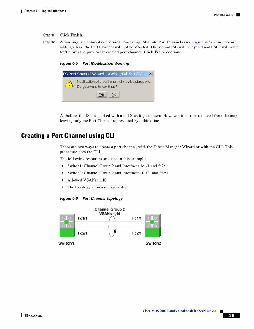
Chapter 4 Logical Interfaces Port Channels
Step 11 Click Finish.
Step 12 A warning is displayed concerning converting ISLs into Port Channels (see Figure 4-5). Since we are adding a link, the Port Channel will not be affected. The second ISL will be cycled and FSPF will route traffic over the previously created port channel. Click Yes to continue.
Figure 4-5 Port Modification Warning
As before, the ISL is marked with a red X as it goes down. However, it is soon removed from the map, leaving only the Port Channel represented by a thick line.
Creating a Port Channel using CLIThere are two ways to create a port channel, with the Fabric Manager Wizard or with the CLI. This procedure uses the CLI.
The following resources are used in this example:
• Switch1: Channel Group 2 and Interfaces fc1/1 and fc2/1
• Switch2: Channel Group 2 and Interfaces: fc1/1 and fc2/1
• Allowed VSANs: 1,10
• The topology shown in Figure 4-7
Figure 4-6 Port Channel Topology
4-5Cisco MDS 9000 Family Cookbook for SAN-OS 2.x
78-xxxxx-xx
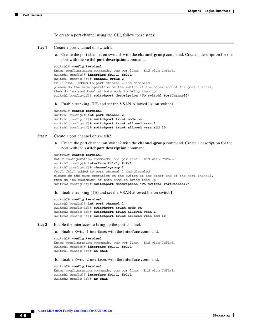
Chapter 4 Logical Interfaces Port Channels
To create a port channel using the CLI, follow these steps:
Step 1 Create a port channel on switch1.
a. Create the port channel on switch1 with the channel-group command. Create a description for the port with the switchport description command.
switch1# config terminalEnter configuration commands, one per line. End with CNTL/Z.switch1(config)# interface fc1/1, fc2/1switch1(config-if)# channel-group 2fc1/1 fc2/1 added to port channel 2 and disabledplease do the same operation on the switch at the other end of the port channel,then do "no shutdown" at both ends to bring them upswitch1(config-if)# switchport description "To switch2 PortChannel2"
b. Enable trunking (TE) and set the VSAN Allowed list on switch1.
switch1# config terminalswitch1(config)# int port channel 2switch1(config-if)# switchport trunk mode onswitch1(config-if)# switchport trunk allowed vsan 1switch1(config-if)# switchport trunk allowed vsan add 10
Step 2 Create a port channel on switch2.
a. Create the port channel on switch2 with the channel-group command. Create a description for the port with the switchport description command.
switch2# config terminalEnter configuration commands, one per line. End with CNTL/Z.switch2(config)# interface fc1/1, fc2/1switch2(config-if)# channel-group 2fc1/1 fc2/1 added to port channel 2 and disabledplease do the same operation on the switch at the other end of the port channel,then do "no shutdown" at both ends to bring them upswitch2(config-if)# switchport description "To switch1 PortChannel2"
b. Enable trunking (TE) and set the VSAN allowed list on switch1
switch2# config terminalswitch2(config)# int port channel 2switch2(config-if)# switchport trunk mode onswitch2(config-if)# switchport trunk allowed vsan 1switch2(config-if)# switchport trunk allowed vsan add 10
Step 3 Enable the interfaces to bring up the port channel.
a. Enable Switch1 interfaces with the interface command.
switch1# config terminalEnter configuration commands, one per line. End with CNTL/Z.switch1(config)# interface fc1/1, fc2/1switch1(config-if)# no shut
b. Enable Switch2 interfaces with the interface command.
switch2# config terminalEnter configuration commands, one per line. End with CNTL/Z.switch2(config)# interface fc1/1, fc2/1switch2(config-if)# no shut
4-6Cisco MDS 9000 Family Cookbook for SAN-OS 2.x
78-xxxxx-xx
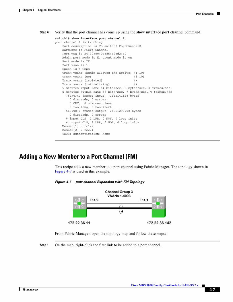
Chapter 4 Logical Interfaces Port Channels
Step 4 Verify that the port channel has come up using the show interface port channel command.
switch1# show interface port channel 2port channel 2 is trunking Port description is To switch2 PortChannel2 Hardware is Fibre Channel Port WWN is 24:02:00:0c:85:e9:d2:c0 Admin port mode is E, trunk mode is on Port mode is TE Port vsan is 1 Speed is 4 Gbps Trunk vsans (admin allowed and active) (1,10) Trunk vsans (up) (1,10) Trunk vsans (isolated) () Trunk vsans (initializing) () 5 minutes input rate 64 bits/sec, 8 bytes/sec, 0 frames/sec 5 minutes output rate 56 bits/sec, 7 bytes/sec, 0 frames/sec 78296342 frames input, 72311141128 bytes 0 discards, 0 errors 0 CRC, 0 unknown class 0 too long, 0 too short 56299070 frames output, 26061293700 bytes 0 discards, 0 errors 0 input OLS, 2 LRR, 0 NOS, 0 loop inits 4 output OLS, 2 LRR, 0 NOS, 0 loop inits Member[1] : fc1/2 Member[2] : fc2/1 iSCSI authentication: None
Adding a New Member to a Port Channel (FM)This recipe adds a new member to a port channel using Fabric Manager. The topology shown in Figure 4-7 is used in this example.
Figure 4-7 port channel Expansion with FM Topology
From Fabric Manager, open the topology map and follow these steps:
Step 1 On the map, right-click the first link to be added to a port channel.
4-7Cisco MDS 9000 Family Cookbook for SAN-OS 2.x
78-xxxxx-xx

Chapter 4 Logical Interfaces Port Channels
Step 2 Click Edit... You see the screen in Figure 4-8.
Figure 4-8 Create Port Channel Wizard
Existing port channel members appear in the Selected column while available candidate links appear in the Available column.
Step 3 Move the available ISL (fc1/1 - fc1/9) into the Selected column.
Step 4 Click Finish...
A warning is displayed concerning modifying a port channel. Since we are adding a link, the port channel will not be affected. However, the ISL will be cycled while FSPF continues to route traffic over the previously created port channel.
Figure 4-9 Port Channel Modification Warning
Step 5 Click Yes.
On the Fabric Manager map, the link selected to be added to the port channel momentarily goes down (represented by a red X) then disappears from the map, leaving only the port channel represented by a thick line.
4-8Cisco MDS 9000 Family Cookbook for SAN-OS 2.x
78-xxxxx-xx

Chapter 4 Logical Interfaces Port Channels
Adding New Members to a Port Channel (CLI)This recipe adds a new member to a port channel using the CLI. These resources are used in the example:
• Switches 1 and 2
• Existing Interfaces fc1/1 and fc2/1
• New Interface fc3/1
Step 1 When adding the new member to switch1, use the force keyword with the channel-group command. The makes new link inherit the parameters of the existing links in channel group 2.
switch1# conf tswitch1(config)# int fc3/1switch1(config-if)# channel-group 2 forcefc3/1 added to port channel 2 and disabledplease do the same operation on the switch at the other end of the port channel,then do "no shutdown" at both ends to bring them upswitch1(config-if)# no shut
Step 2 When adding the new member to switch2, use the force keyword with the channel-group command. The makes new link inherit the parameters of the existing links in channel group 2.
switch2# conf tswitch2(config)# int fc3/1switch2(config-if)# channel-group 2 forcefc3/1 added to port channel 2 and disabledplease do the same operation on the switch at the other end of the port channel,then do "no shutdown" at both ends to bring them upswitch3(config-if)# no shut
Step 3 Verify that the port channel now has three members using the show interface port channel command.
switch1# show interface port channel 2port channel 2 is trunking Port description is To switch2 PortChannel2 Hardware is Fibre Channel Port WWN is 24:02:00:0c:85:e9:d2:c0 Admin port mode is E, trunk mode is on Port mode is TE Port vsan is 1 Speed is 6 Gbps Trunk vsans (admin allowed and active) (1,10) Trunk vsans (up) (1,10) Trunk vsans (isolated) () Trunk vsans (initializing) () 5 minutes input rate 64 bits/sec, 8 bytes/sec, 0 frames/sec 5 minutes output rate 56 bits/sec, 7 bytes/sec, 0 frames/sec 78296342 frames input, 72311141128 bytes 0 discards, 0 errors 0 CRC, 0 unknown class 0 too long, 0 too short 56299070 frames output, 26061293700 bytes 0 discards, 0 errors 0 input OLS, 2 LRR, 0 NOS, 0 loop inits 4 output OLS, 2 LRR, 0 NOS, 0 loop inits Member[1] : fc1/2 Member[2] : fc2/1 Member[3] : fc3/1 iSCSI authentication: None
4-9Cisco MDS 9000 Family Cookbook for SAN-OS 2.x
78-xxxxx-xx
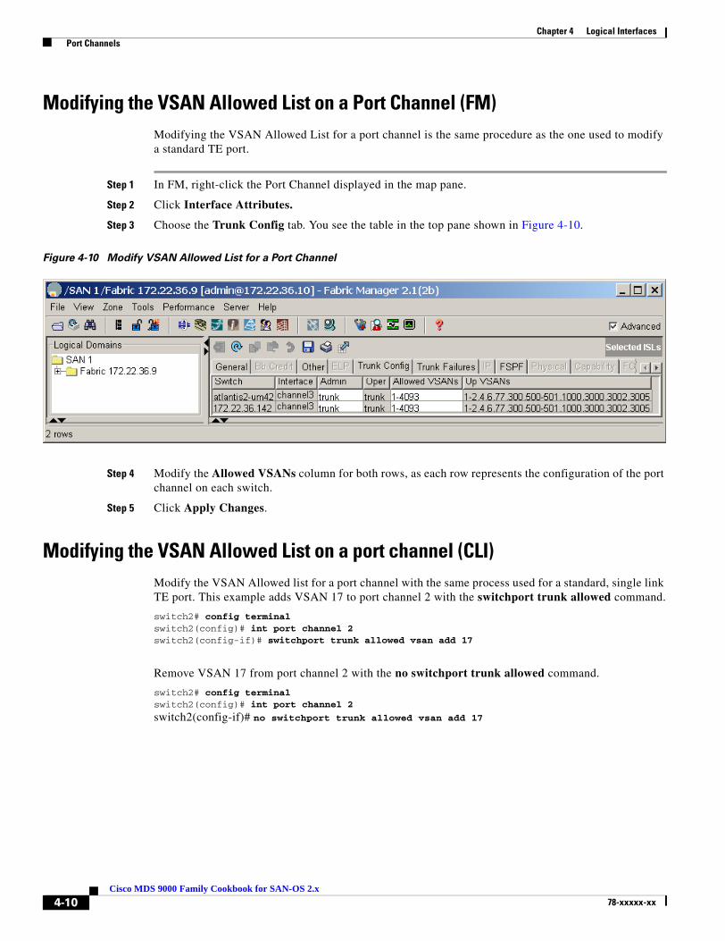
Chapter 4 Logical Interfaces Port Channels
Modifying the VSAN Allowed List on a Port Channel (FM)Modifying the VSAN Allowed List for a port channel is the same procedure as the one used to modify a standard TE port.
Step 1 In FM, right-click the Port Channel displayed in the map pane.
Step 2 Click Interface Attributes.
Step 3 Choose the Trunk Config tab. You see the table in the top pane shown in Figure 4-10.
Figure 4-10 Modify VSAN Allowed List for a Port Channel
Step 4 Modify the Allowed VSANs column for both rows, as each row represents the configuration of the port channel on each switch.
Step 5 Click Apply Changes.
Modifying the VSAN Allowed List on a port channel (CLI)Modify the VSAN Allowed list for a port channel with the same process used for a standard, single link TE port. This example adds VSAN 17 to port channel 2 with the switchport trunk allowed command.
switch2# config terminalswitch2(config)# int port channel 2switch2(config-if)# switchport trunk allowed vsan add 17
Remove VSAN 17 from port channel 2 with the no switchport trunk allowed command.
switch2# config terminalswitch2(config)# int port channel 2
switch2(config-if)# no switchport trunk allowed vsan add 17
4-10Cisco MDS 9000 Family Cookbook for SAN-OS 2.x
78-xxxxx-xx

Cisco MDS 9078-xxxxx-xx
C H A P T E R 5
VSANsA VSAN (Virtual SAN) is a logical grouping of ports in a single switch or across multiple switches that function like a single fabric. Each VSAN has all the required fabric services independent of the other VSANs configured on the same switch or set of switches. VSANs also provide SAN island consolidation on a higher port density physical switch, along with traffic isolation and increased security.
VSANs are numbered from 1 through 4094. VSAN 1 and VSAN 4094 are predefined and have very specific roles. VSAN 1 is the default VSAN that contains all ports by default. VSAN 4094 is the isolated VSAN into which orphaned ports are assigned.
Creating a VSAN and Adding InterfacesThis recipe creates a VSAN (3005) and adds an interface to it.
Note Moving a port from one VSAN to another does not change its configuration (F, FL, TL), its speed or its administrative state (shut/noshut). However, any device attached to the port needs to FLOGI back into the switch.
From Fabric Manager, create a VSAN by following these steps:
Step 1 On the toolbar, click the Create VSAN icon.
Step 2 Select the switch(es) for the VSAN.
Step 3 Enter the VSAN ID.
Step 4 Enter a name for the VSAN.
Step 5 If the VSAN will be attaching to a third party switch, select the appropriate Interop Mode.
Note In SAN-OS 2.1(2), a static domainID can be specified for a VSAN at the time of creation. Otherwise the recipe in Converting an Existing VSAN to Static DomainID and Enabling Persistent FCID using CLI, page 5-9 should be followed to specify the new domainID.
Step 6 Click Create.
5-100 Family Cookbook for SAN-OS 2.x

Chapter 5 VSANs Creating a VSAN and Adding Interfaces
To add interfaces to the new VSAN in Fabric Manager, follow these steps:
Step 1 In the Physical Attributes pane, expand Switches > Interfaces.
Step 2 Select FC Physical.
Step 3 Modify the Port VSAN Config field for the switch interface to be moved to the specified VSAN.
Step 4 Optionally, if the port has the Admin Status down, enable it by changing the value to up.
Step 5 Click Apply Changes....
A warning is displayed that moving a port between two VSANs can be disruptive to that port as it will have to relogin to the fabric and will no longer have access to resources in the previous VSAN.
Step 6 Click Yes to move the port to the new VSAN.
5-2Cisco MDS 9000 Family Cookbook for SAN-OS 2.x
78-xxxxx-xx

Chapter 5 VSANs Modifying VSAN Attributes with Fabric Manager
Modifying VSAN Attributes with Fabric ManagerThese recipes modify the attributes of a VSAN using Fabric Manager. The attributes of a VSAN include:
• VSAN Name
• LoadBalancing (src/dst or src/dst/ox-id)
• Administrative State (suspended or active)
• Interoperability Mode to work with third party switches
• Order Delivery
• Static domain IDs
• Persistent FCIDs
Step 1 Select a fabric in the Logical Domains pane.
Step 2 Expand the VSAN to be modified (VSAN 3001 in Figure 5-1).
Step 3 Choose VSAN Attributes.
Step 4 Make changes to the desired fields.
Note Standard editing keyboard shortcuts (ctrl-x to cut; ctrl-c to copy; ctrl-v to paste) can be used to edit the text fields.
Step 5 Click Apply Changes....
Figure 5-1 Modify VSAN Attributes
5-3Cisco MDS 9000 Family Cookbook for SAN-OS 2.x
78-xxxxx-xx

Chapter 5 VSANs Modifying VSAN Attributes with Fabric Manager
Converting an Existing VSAN DomainID and Enabling FCID with Fabric Manager
Within a VSAN, the domain manager process on the principal switch in a fabric is responsible for assigning a domain_ID to a switch joining the fabric. When a switch boots up or joins a new fabric, it can request a specific domain_ID or take any available domain_ID.
A domain_ID can be configured in one of two ways:
• Preferred: The new switch requests a specific domain_ID. However, if it receives a different domain_ID, it accepts it.
• Static: The new switch requests a specific domain_ID. If it receives a different domain_ID, it isolates itself from the fabric. Use static domain IDs when the same domain_ID must be maintained under all circumstances.
After obtaining the domain_ID from the principal switch in the VSAN, the local switch assigns Fibre Channel Identifiers (FC_IDs) to each end device as they log into the fabric. This process is known as FLOGI (Fabric Login).
Tip HPUX and AIX are two operating systems that use a FC_ID in the device path to storage. For the switch to always assign the same FC_ID to a device across switch reboots, configure a persistent FC_ID and static domain_ID for the VSAN. If an FC_ID changes for a device accessed by either an AIX or a HPUX host, the host may lose access to the device.
By default, the switch assigns the same FC_ID to a device. However, if the switch is rebooted this database of pwwn/FC_ID mapping is not maintained. Enabling persistent FC_IDs will make this database persistent across reboots.
A persistent FC_ID can be configured two ways:
– Dynamic (default): The FC_ID is determined and assigned by the switch and if the persistent FC_ID database is manually purged by the user this entry will be deleted. These entries are persistent across reboots of the switch and are VSAN specific.
– Static: The FC_ID is determined by the user prior to attaching the device to the switch. If the persistent FC_ID database is manually purged by the user these entries will not be removed. These entries are persistent across reboots of the switch and are VSAN specific.
When persistent FC_ID is enabled, the switch will make persistent all of the devices in that VSAN, therefore the admin is not required to manually type in devices entering that VSAN.
In this procedure, an existing VSAN (3000) on switch 172.22.36.11 with domain_ID 239 is statically configured. Then a persistent FCID is enabled using FM. This recipe does not alter the running domain_ID.
To configure the switch and enable persistent FCID, follow these steps from Fabric Manager:
Step 1 In the Logical Domains pane, expand the VSAN to be modified then choose Domain Manager (see Figure 5-2).
Step 2 Choose the Configuration tab (see Figure 5-2).
Step 3 Enter the domain_ID from the Running domain_ID (239) column in the Config domain_ID column (239) (see Figure 5-2).
5-4Cisco MDS 9000 Family Cookbook for SAN-OS 2.x
78-xxxxx-xx

Chapter 5 VSANs Modifying VSAN Attributes with Fabric Manager
Step 4 Change the IdType field to static (see Figure 5-2).
Figure 5-2 Enabling Static Domain_ID
Step 5 Click the green Apply Changes... icon (see Figure 5-2).
Step 6 Choose the Persistent Setup tab.
Step 7 Check the Enable checkbox.
5-5Cisco MDS 9000 Family Cookbook for SAN-OS 2.x
78-xxxxx-xx
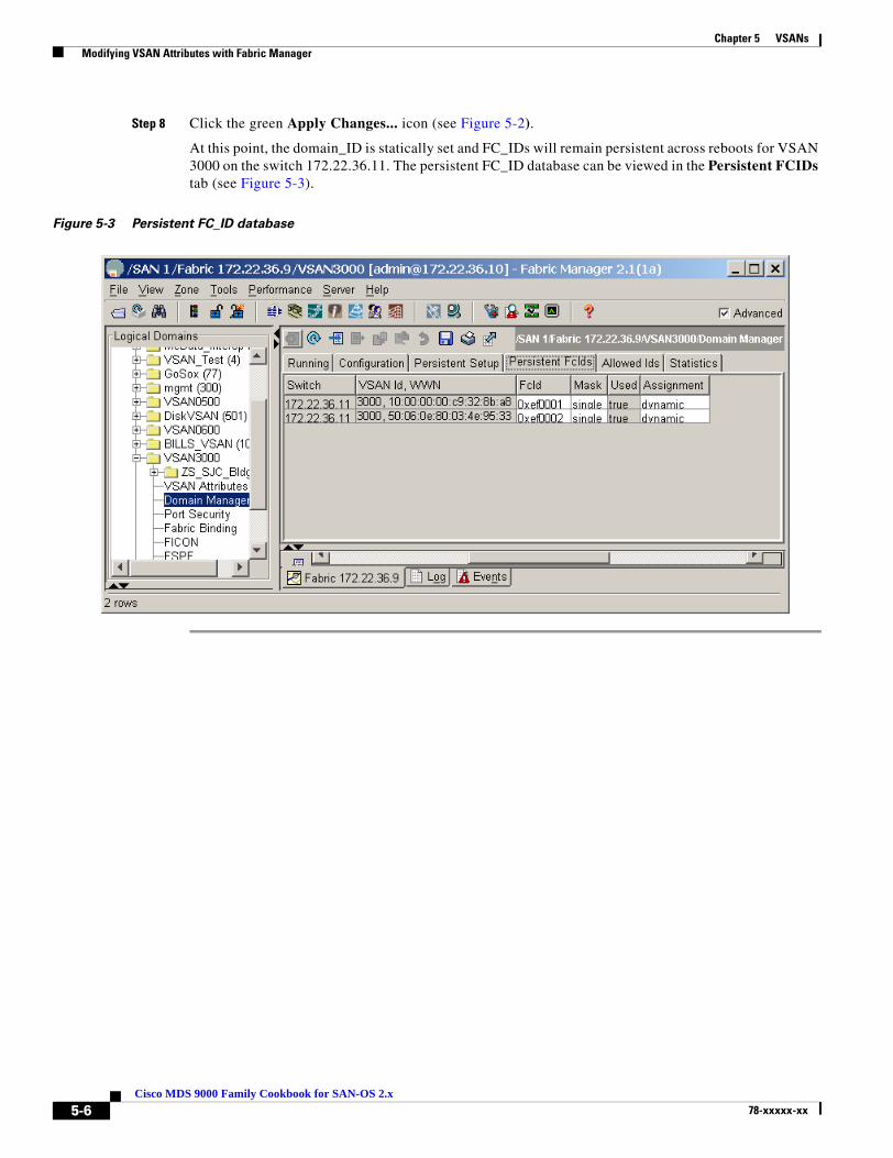
Chapter 5 VSANs Modifying VSAN Attributes with Fabric Manager
Step 8 Click the green Apply Changes... icon (see Figure 5-2).
At this point, the domain_ID is statically set and FC_IDs will remain persistent across reboots for VSAN 3000 on the switch 172.22.36.11. The persistent FC_ID database can be viewed in the Persistent FCIDs tab (see Figure 5-3).
Figure 5-3 Persistent FC_ID database
5-6Cisco MDS 9000 Family Cookbook for SAN-OS 2.x
78-xxxxx-xx

Chapter 5 VSANs Modifying VSAN Attributes with the CLI
Modifying VSAN Attributes with the CLIThese recipes modify the attributes of a VSAN using the CLI. This includes interop modes, load balancing, and setting static domain IDs and persistent FCIDs.
Creating a VSAN on a single switch and adding an InterfaceCreate and name a VSAN on a single switch with the vsan name command. In this example, VSAN 200 is created with the name TapeVSAN and fibre channel interface fc 1/1 is added with the vsan interface command.
switch1# conf tEnter configuration commands, one per line. End with CNTL/Z.switch(config)# vsan database switch(config-vsan-db)# vsan 200 name TapeVSANswitch(config-vsan-db)# vsan 200 interface fc 1/1switch(config-vsan-db)# ^Zswitch#
Setting VSAN Interop ModeSet Interop mode for VSANs that need to interact with other 3rd party switches. Use different Interop modes under different circumstance as listed in Table 5-1.
Table 5-1 Table Interop Modes
For more information, refer to the MDS Switch to Switch Interoperability Configuration Guide on CCO. Consult this manual prior to doing interoperability tasks; it explains the different Interop modes.
The following examples set Interop modes to 1, 2, and 3 for a VSAN.
Interop mode When you use it
1 Required when all vendor switches are set in their respective interop modes. In interop mode 1, only Domain IDs 97 to 127 are allowed.
2 Required when VSAN has to work with a Brocade 2800/3800 switch in native corePID 0 mode.
3 Required when the VSAN has to work with a Brocade switch running in corePID 1 mode.
5-7Cisco MDS 9000 Family Cookbook for SAN-OS 2.x
78-xxxxx-xx

Chapter 5 VSANs Modifying VSAN Attributes with the CLI
Interop Mode 1
Interop mode 1 is required when all vendor switches are set in their respective interop modes. Be sure the domain ID of the VSAN is between 97 – 127 for mode 1 to work. Change the interop mode with the vsan interop command.
switch# conf tEnter configuration commands, one per line. End with CNTL/Z.switch(config)# vsan database switch(config-vsan-db)# vsan 200 interop 1switch(config-vsan-db)# ^Zswitch#
Interop Mode 2
Interop mode 2 is required when a VSAN has to work with a Brocade 2800/3800 switch in native corePID 0 mode. Change the interop mode with the vsan interop command.
switch# conf tEnter configuration commands, one per line. End with CNTL/Z.switch(config)# vsan database switch(config-vsan-db)# vsan 200 interop 2switch(config-vsan-db)# ^Zswitch#
Interop Mode 3
Interop mode 3 is required when a VSAN has to work with a Brocade switch running in corePID 1 mode. Change the interop mode with the vsan interop command.
switch# conf tEnter configuration commands, one per line. End with CNTL/Z.switch(config)# vsan database switch(config-vsan-db)# vsan 200 interop 3switch(config-vsan-db)# ^Zswitch#
Changing the Load-balancing SchemeConfigure the load-balancing scheme with VSAN. S_ID (source id), D_ID (destination id) based load balancing, and the exchange level (S_ID, D_ID, OX_ID) on the switch
These recipes configure load-balancing for VSAN 200.
Sequence Level load-balancing (Source_ID, Destination_ID)
Change the load-balancing scheme for VSAN 200 to S_ID, D_ID mode with the vsan loadbalancing command.
switch# conf tEnter configuration commands, one per line. End with CNTL/Z.switch(config)# vsan database switch(config-vsan-db)# vsan 200 loadbalancing src-dst-idswitch(config-vsan-db)# ^Zswitch#
5-8Cisco MDS 9000 Family Cookbook for SAN-OS 2.x
78-xxxxx-xx

Chapter 5 VSANs Modifying VSAN Attributes with the CLI
Exchange level load balancing (S_ID, D_ID, OX_ID)
Change the load-balancing scheme for VSAN 200 to S_ID, D_ID, and OX_ID modes with the vsan loadbalancing command. This is the default load balancing scheme.
switch# conf tEnter configuration commands, one per line. End with CNTL/Z.switch(config)# vsan database switch(config-vsan-db)# vsan 200 loadbalancing src-dst-ox-idswitch(config-vsan-db)# endswitch#
Converting an Existing VSAN to Static DomainID and Enabling Persistent FCID using CLI
This recipe configures static a Domain_ID for a VSAN and enables persistent FC_ID for the same VSAN.
In this FM procedure an existing VSAN (3000) on switch 172.22.36.11 with domain_ID 239 is statically configured and the persistent FCID is enabled. This recipe does not alter the running domain_ID.
Step 1 Display the current domain_ID for VSAN 3000 using the command show domain-list.
172.22.36.11# show fcdomain domain-list vsan 3000Number of domains: 2Domain ID WWN--------- -----------------------0xef(239) 2b:b8:00:05:30:00:68:5f [Local] [Principal]
Step 2 Configure the static domain_ID with the domain static command.
172.22.36.11# conf tEnter configuration commands, one per line. End with CNTL/Z.172.22.36.11(config)# fcdomain domain 239 static vsan 3000
Step 3 Enable persistent FC_ID with fcid persistent.
172.22.36.11(config)# fcdomain fcid persistent vsan 3000172.22.36.11(config)# end
Step 4 Save the configuration:
172.22.36.11# copy running-config startup-config[########################################] 100%
Note If the domain ID of VSAN 200 is different than what is currently running (22 in this case) then the VSAN has to be restarted before configuration changes to the Domain_ID and FC_ID persistence take effect. Changing Domain_IDs and hence FC_IDs for a device is disruptive because an end device has to relogin to the fabric (FLOGI) to obtain a new FCID.
5-9Cisco MDS 9000 Family Cookbook for SAN-OS 2.x
78-xxxxx-xx
Chapter 5 VSANs Modifying VSAN Attributes with the CLI
Caution Changing Domain_IDs and therefore FC_IDs for a device is disruptive, as an end device has to relogin to the fabric (FLOGI) to obtain a new FCID. However, making a Domain_ID static without changing its value is not disruptive.
Restarting a VSANSometimes the VSAN on a switch needs to be restarted. For example, after changing the Domain_ID of a VSAN, restart the VSAN for the new Domain_ID to take effect.
Restart VSAN (200) with the suspend and no suspend commands.
switch# conf tEnter configuration commands, one per line. End with CNTL/Z.switch(config)# vsan databaseswitch(config-vsan-db)# vsan 200 suspendswitch(config-vsan-db)# no vsan 200 suspendswitch(config-vsan-db)# end
Assigning a Predetermined FCID to a PWWNWhen performing a migration or hba replacement, the FCID may need to be re-assigned to the new pWWN. This recipe assigns a pre-determined FC_ID to a specific pWWN.
Note A new FCID cannot be assigned to a pWWN that is logged into the fabric. Before assigning a new FCID, log the device out of the fabric. You can log out the device by shutting down the FC interface.
FC_ID 0x160000 will be assigned to pWWN 50:06:0b:82:bf:d1:db:cd permanently. Therefore, when the pWWN logs into the switch (FLOGI) it will get this assigned FC_ID.
Note The FC_ID to be assigned (0x160000) should contain the same Domain_ID (0x16) as the currently running domain in the VSAN.
To assign a pre-determined FC_ID to a specific pWWN, follow this example:
switch# conf tEnter configuration commands, one per line. End with CNTL/Z.switch(config)# fcdomain fcid database switch(config-fcid-db)# vsan 22 wwn 50:06:0b:82:bf:d1:db:cd fcid 0x160000 dynamicswitch(config-fcid-db)# ^Zswitch#
5-10Cisco MDS 9000 Family Cookbook for SAN-OS 2.x
78-xxxxx-xx

Cisco MDS 9078-xxxxx-xx
C H A P T E R 6
ZoningZones and zone sets are the basic form of data path security in a fibre channel environment. A zone set is a collection of zones that, in turn, have individual members in them. Only those members within the same zone can communicate with each other. A device can be a member of multiple zones and those devices not in a zone are in the ‘default zone’. The policy for the ‘default-zone’ can either be permit (devices see each other) or deny (devices in the default-zone can not see each other).
The basic flow of zoning is to:
1. Create zones.
2. Add hosts and storage to the zones.
3. Create zone sets.
4. Add the zones to the zone sets.
5. Activate the zone sets.
This chapter focuses on creating zones and zone sets, and manipulating them. Both basic zoning (FC-GS-3) and enhanced zoning (FC-GS-4 introduced in SAN-OS 2.0) use the concepts of zones and zone sets.
Enhanced ZoningEnhanced zoning, introduced in SAN-OS 2.0, was defined in the FC-GS-4 and FC-SW-3 standards. It provides significant enhancements to basic zoning. Enhanced zoning:
• Has a VSAN scope, so that while VSAN X is using enhanced zoning, other VSANs can continue to use basic zoning.
• Is IVR compatible.
• Provides session locking, so that two SAN administrators cannot simultaneously modify a zoning database within a VSAN.
• Provides implicit full zone set distribution, so that the zone set database local to each switch remains in sync when a zone set is modified.
• Allows full zone set changes to be distributed without having to activate a zone set. Use this to ready features in the daytime and activate the zone set at night.
• Stages modifications until they are explicitly committed or aborted, allowing the SAN admin to review changes prior to activation.
6-100 Family Cookbook for SAN-OS 2.x

Chapter 6 Zoning Enhanced Zoning
• Can control how a zone merge is done. Merging can be accomplished either by performing a union of two zone sets according to the same rules as basic zoning, or by merging only identical active zone sets. The latter method prevents accidental merging.
Enhanced zoning uses the same techniques and tools as basic zoning, with a few added commands that are covered in these recipes. The flow of enhanced zoning, however, differs from that of basic zoning. For one thing, a VSAN-wide lock, if available, is implicitly obtained for enhanced zoning. Second, all zone and zone set modifications for advanced zoning include activation. Last, changes are either committed (put into production) or aborted (pending changes are scrapped) with advanced zoning. The flow is illustrated in Figure 6-1.
Figure 6-1 Enhanced Zoning Flowchart
Enabling Enhanced ZoningEnhanced zoning, with its VSAN scope, requires that all switches in a VSAN be capable of enhanced zoning and have enhanced zoning enabled later on. Due to its distributed architecture and abilities, enhanced zoning is enabled only on one switch in the VSAN. Commands are then propagated to other switches in the VSAN. The rules for enabling enhanced zoning with Fabric Manager are as follows.
• Enhanced zoning is enabled on only one switch in the VSAN. Attempting to enable it on multiple switches in the same VSAN can result in a failure to activate.
• Enabling enhanced zoning does not trigger a zone set activation.
6-2Cisco MDS 9000 Family Cookbook for SAN-OS 2.x
78-xxxxx-xx
Chapter 6 Zoning Enhanced Zoning
• The switch chosen to perform migration distributes its full zone database to other switches in the VSAN, thereby overwriting the destination switches’ full zone set database. It is critical that you select the correct switch for enhanced zoning – otherwise, you can accidentally delete the wrong full zone set database.
Enabling Enhanced Zoning with the CLI
To enable enhanced zoning with the CLI, follow these steps:
Step 1 Enter config term mode and enable enhanced zoning with the command zone mode enhanced.
switch# conf tEnter configuration commands, one per line. End with CNTL/Z.switch(config)# zone mode enhanced vsan 3000Set zoning mode command initiated. Check zone statusswitch(config)#
Step 2 Display the zoning status with the command show zone status.
switch# show zone status vsan 3000VSAN: 3000 default-zone: deny distribute: active only Interop: default mode: enhanced merge-control: allow session: none hard-zoning: enabledDefault zone: qos: low broadcast: disabled ronly: disabledFull Zoning Database : Zonesets:1 Zones:3 Aliases: 1 Attribute-groups: 1Active Zoning Database : Name: ZoneSet1 Zonesets:1 Zones:2Status: Set zoning mode complete at 16:22:51 pacific Oct 03 2005
Enabling Enhanced Zoning with Fabric Manager
To enable enhanced zoning with Fabric Manager, follow these steps:
Step 1 In the Logical Domains pane, choose a VSAN then the folder corresponding to the name of the active zone set (see Figure 6-2). If no active zone set exists, choose ‘default zone’.
Step 2 Choose the Enhanced Tab (see Figure 6-2).
Step 3 In the action column for the enabling switch, change the cell to Enhanced (see Figure 6-2). From now on, this switch distributes its full zone database for this VSAN, overwriting all other switches in the enhanced zone database.
6-3Cisco MDS 9000 Family Cookbook for SAN-OS 2.x
78-xxxxx-xx
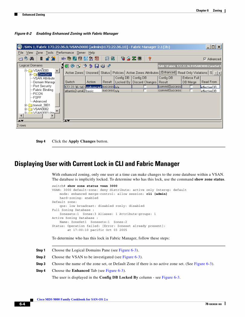
Chapter 6 Zoning Enhanced Zoning
Figure 6-2 Enabling Enhanced Zoning with Fabric Manager
Step 4 Click the Apply Changes button.
Displaying User with Current Lock in CLI and Fabric ManagerWith enhanced zoning, only one user at a time can make changes to the zone database within a VSAN. The database is implicitly locked. To determine who has this lock, use the command show zone status.
switch# show zone status vsan 3000VSAN: 3000 default-zone: deny distribute: active only Interop: default mode: enhanced merge-control: allow session: cli [admin] hard-zoning: enabledDefault zone: qos: low broadcast: disabled ronly: disabledFull Zoning Database : Zonesets:1 Zones:3 Aliases: 1 Attribute-groups: 1Active Zoning Database : Name: ZoneSet1 Zonesets:1 Zones:2Status: Operation failed: [Error: Zoneset already present]: at 17:00:10 pacific Oct 03 2005
To determine who has this lock in Fabric Manager, follow these steps:
Step 1 Choose the Logical Domains Pane (see Figure 6-3).
Step 2 Choose the VSAN to be investigated (see Figure 6-3).
Step 3 Choose the name of the zone set, or Default Zone if there is no active zone set. (See Figure 6-3).
Step 4 Choose the Enhanced Tab (see Figure 6-3).
The user is displayed in the Config DB Locked By column - see Figure 6-3.
6-4Cisco MDS 9000 Family Cookbook for SAN-OS 2.x
78-xxxxx-xx

Chapter 6 Zoning Enhanced Zoning
Figure 6-3 Displaying the Enhanced Zoning Lock
6-5Cisco MDS 9000 Family Cookbook for SAN-OS 2.x
78-xxxxx-xx

Chapter 6 Zoning Zone Sets
Zone SetsZone sets are containers for zones. There are two types of zone sets on the MDS platform, active zone sets and local zone sets.
• Active Zone set: is the rules by which the MDS platform enforces its zoning security policy.It cannot be modified and is distributed to all switches in the VSAN. There are specific rules to merging the active zone set when two switches are connected by an ISL as set by the FC standards.
• Local Zone set(s): are contained in the full zone set database on the switch. The zone sets are edited directly and then activated to become the active zone set. They can optionally be distributed to other switches, either manually or when a zone set is activated.
Distributing Zone Sets The zone set in the full zone set database can be distributed to other switches either during activation or manually when basic zoning is enabled. When enhanced zoning is enabled, the full zone set is always distributed when changes are committed to the full zone set database. The full zone set is always enabled for enhanced zoning.
Tip This feature should be enabled on all switches in the fabric, and can be specified in the initial setup script. This is also the default behavior when enhanced zoning is enabled.
Distributing Zone Sets Automatically
Enabling automatic full zone set distribution distributes the local zone set to all other switches in the VSAN when a zone set is activated.
Note When two VSANs with full zone set distribution enabled are merged, they try to merge the full zone set database according to standard zone set merge rules. Failure to merge the full zone set database does not isolate the ISL; only failure to merge the active zone set results in an isolated ISL. This failure to merge the full zone set database produces the syslog error message:
2005 Oct 5 14:35:59 172.22.36.142 %ZONE-2-ZS_MERGE_FULL_DATABASE_MISMATCH: %$VSAN 1000%$ Zone merge full database mismatch on interface fc1/1
Distributing Zone Sets Automatically with the CLI
Automatically distribute zone sets with the command zoneset distribute.
ca-9506# conf tEnter configuration commands, one per line. End with CNTL/Z.ca-9506(config)# zoneset distribute full vsan 804
6-6Cisco MDS 9000 Family Cookbook for SAN-OS 2.x
78-xxxxx-xx

Chapter 6 Zoning Zone Sets
Distributing Zone Sets Automatically with Fabric Manager
To automatically distribute zone sets with Fabric Manager, follow these steps
Step 1 In the Logical Domains window, choose the fabric.
Step 2 Choose the VSAN to be modified.
Step 3 Select the name of the Active Zone Set (or default zone if none is active).
Step 4 Choose the Policies tab.
Step 5 Change the Propagation field to FullZoneSet for all switches in that VSAN.
Step 6 Click the green Apply Changes icon.
Distributing Zone Sets Manually
You can distribute the full zone set database to other switches without activating a zone set. Do this when a new switch is brought into the fabric and the zone set with its zones and FC aliases need to be distributed. This zoneset distribute command overwrites the existing zone set database in the target switch.
ca-9506# zoneset distribute vsan 804Zoneset distribution initiated. check zone status
6-7Cisco MDS 9000 Family Cookbook for SAN-OS 2.x
78-xxxxx-xx

Chapter 6 Zoning Zones
ZonesIn order for two devices to communicate, they must be in the same zone. Valid members of a zone are:
• Port WWN
• FC Alias
• FCID
• FWWN (WWN of a FC interface)
• Switch Interface (fc X/Y)
• Symbolic node name
• Distributed Device Alias
The four most common zone member types are the pWWN, device alias, FC alias and the switch interface.
Tip We recommend that you use the device alias for zoning because they provide hardware-enforced zoning and tie a zone member to a specific hba rather than to the switch port. Also, device aliases have the added benefit of being VSAN-independent and are based on an easy-to-understand name rather than a cryptic pWWN.
Equally important is the name of the zone. Environments use many different zone names. However, all name formats should provide relevant information as to their contents. Names like “Zone1” or “TapeZone” do not provide sufficient information about their contents.
Tip A zone should contain two members and the zone name should contain identifiers related to the two devices (for example, Z_testhost_fcaw0_symm13FA3aa). That name may be longer than Z_testhost_hba0, but it provides detailed information about the contents. You will not have to consult further sources of documentation.
Creating a Zone and Adding it to a Zone Set with Fabric ManagerThis recipe creates a zone set, creates zones, adds them to the zone set, then activates the zone set. The method used is the same for both basic zoning and enhanced zoning. The following topology is used:
Figure 6-4 Fabric Manager Zoning Topology
6-8Cisco MDS 9000 Family Cookbook for SAN-OS 2.x
78-xxxxx-xx
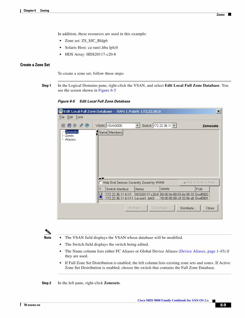
Chapter 6 Zoning Zones
In addition, these resources are used in this example:
• Zone set: ZS_SJC_Bldg6
• Solaris Host: ca-sun1,hba lpfc0
• HDS Array: HDS20117-c20-8
Create a Zone Set
To create a zone set, follow these steps:
Step 1 In the Logical Domains pane, right-click the VSAN, and select Edit Local Full Zone Database. You see the screen shown in Figure 6-5
Figure 6-5 Edit Local Full Zone Database
Note • The VSAN field displays the VSAN whose database will be modified.
• The Switch field displays the switch being edited.
• The Name column lists either FC Aliases or Global Device Aliases (Device Aliases, page 1-45) if they are used.
• If Full Zone Set Distribution is enabled, the left column lists existing zone sets and zones. If Active Zone Set Distribution is enabled, choose the switch that contains the Full Zone Database.
Step 2 In the left pane, right-click Zonesets.
6-9Cisco MDS 9000 Family Cookbook for SAN-OS 2.x
78-xxxxx-xx

Chapter 6 Zoning Zones
Step 3 In the resulting popup menu, select Insert...
Step 4 Enter a zone set name, such as ZS_SJ_Bldg6, then click OK.
At this point a zone set has been created. The next phase is to create a zone and add members to it.
Create a Zone and Add Members
To create a zone and add members to it from Fabric Manager, follow these steps:
Step 1 Right click on Zones.
Step 2 In the resulting popup menu, select Insert...
Step 3 Enter a meaningful zone name such as ca-sun1_lpfc0_HDS20117-c20-8 to represent both the initiator and target in the name.
Step 4 Click OK.
You see the dialog in.Figure 6-6.
Figure 6-6 Zone Database after Creating Zone Set and Zones
Step 5 Drag the two end devices from the bottom pane into the new zone. This creates a pWWN-based zone. If non-pWWN zone members (such as interface, FCID or Global Device Alias) are needed, refer to Creating Non-pWWN Based Zones, page 6-13 to specify these member types before continuing.
6-10Cisco MDS 9000 Family Cookbook for SAN-OS 2.x
78-xxxxx-xx

Chapter 6 Zoning Zones
Figure 6-7 Zone with Newly Added Members
This zone is created, as shown in Figure 6-7. Next, add the zone to the zone set.
Add the Zone to the Zone Set and Activate It
To add the zone to the zone set, follow these steps:
Step 1 In the left pane, drag the zone (ca-sun1_lpfc0_HDS20117-c20-8) into the zone set (ZS_SJC_Bldg6). The zoneset’s icon changes by appending a folder icon, and it expands with the newly added zone underneath it.
6-11Cisco MDS 9000 Family Cookbook for SAN-OS 2.x
78-xxxxx-xx

Chapter 6 Zoning Zones
Figure 6-8 Zone Added to Zone Set
Now activate the new zone set. This instructs the switch program to update its Access Control Lists, and modify the running configuration of the zone server to allow the two devices to communicate. When enhanced zoning is enabled, clicking Activate commits the changes as well.
Step 2 In the left pane, right-click the zone set (ZS_SJC_BLDG6) and choose Activate...
a. If the current Active zone set is empty, click Continue Activation...
b. If the current Active zone set is not empty, clicking Proposed Changes displays what is being added or removed from the active zone set.
Step 3 Click Continue Activation...
Figure 6-9 Zone Set Proposed Changes
The zone set is now active and the two end devices can communicate.
6-12Cisco MDS 9000 Family Cookbook for SAN-OS 2.x
78-xxxxx-xx
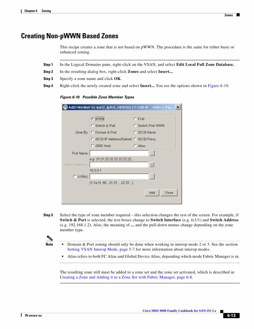
Chapter 6 Zoning Zones
Creating Non-pWWN Based ZonesThis recipe creates a zone that is not based on pWWN. The procedure is the same for either basic or enhanced zoning.
Step 1 In the Logical Domains pane, right-click on the VSAN, and select Edit Local Full Zone Database.
Step 2 In the resulting dialog box, right-click Zones and select Insert...
Step 3 Specify a zone name and click OK.
Step 4 Right-click the newly created zone and select Insert... You see the options shown in Figure 6-10.
Figure 6-10 Possible Zone Member Types
Step 5 Select the type of zone member required – this selection changes the rest of the screen. For example, if Switch & Port is selected, the text boxes change to Switch Interface (e.g. fc1/1) and Switch Address (e.g. 192.168.1.2). Also, the meaning of ... and the pull-down menus change depending on the zone member type.
Note • Domain & Port zoning should only be done when working in interop mode 2 or 3. See the section Setting VSAN Interop Mode, page 5-7 for more information about interop modes.
• Alias refers to both FC Alias and Global Device Alias, depending which mode Fabric Manager is in.
The resulting zone still must be added to a zone set and the zone set activated, which is described in Creating a Zone and Adding it to a Zone Set with Fabric Manager, page 6-8.
6-13Cisco MDS 9000 Family Cookbook for SAN-OS 2.x
78-xxxxx-xx

Chapter 6 Zoning Zones
Creating a Zone and Adding it to a Zone Set with the CLI Standalone MethodThis procedure creates a single zone for a Solaris host with a disk storage port, then adds the zone to the zone set ZS_Engr_primary. This is done with the standalone method, which does not automatically add the zone to the zone set upon creation of the zone.
You can also use this procedure to add an existing zone to a zone set. The procedure is the same for both basic zoning and enhanced zoning with one exception. With enhanced zoning, the pending database must be committed at the end.
This example uses pWWNs as zone members, – obtain pWWNs either from the device itself or from the show flogi database vsan 804 command.
The topology in Figure 6-11 is used in the example.
Figure 6-11 Standalone Zoning Topology
These resources are also used in this example:
• Zone set: ZS_Engr_primary
• Solaris host1, hba instance fcaw0: 22:35:00:0c:85:e9:d2:c2
• Symmetrix 78, FA port 03ab: 10:00:00:00:c9:32:8b:a8
To create a single zone for a Solaris host with a disk storage port, follow these steps:
Step 1 Create the zone with the zone name command. Use a zone name that reflects the names of the members. Then add members to the zone with the member pwwn command
ca-9506# config terminalEnter configuration commands, one per line. End with CNTL/Z.ca-9506(config)# zone name Z_host1_fcaw0_symm78FA03ab vsan 804ca-9506(config-zone)# member pwwn 22:35:00:0c:85:e9:d2:c2ca-9506(config-zone)# member pwwn 10:00:00:00:c9:32:8b:a8
Step 2 Add the zone to the zone set with the zoneset name command.
ca-9506(config)# zoneset name ZS_Engr_primary vsan 804ca-9506(config-zoneset)# member Z_host1_fcaw0_symm78FA03ab
Step 3 Display the zone set with the show zoneset name command.
ca-9506# show zoneset name ZS_Engr_primary vsan 804zoneset name ZS_Engr_primary vsan 804 zone name Z_host1_fcaw0_symm78FA03ab vsan 804 pwwn 22:35:00:0c:85:e9:d2:c2 pwwn 10:00:00:00:c9:32:8b:a8
Step 4 Put the zone set into production with the command zoneset activate name ZS_Engr_primary vsan 804. This activates all the zones in the zone set, not just the new one. With enhanced zoning, the zone set must still be committed in Step 5.
ca-9506(config)# zoneset activate name ZS_Engr_primary vsan 804
6-14Cisco MDS 9000 Family Cookbook for SAN-OS 2.x
78-xxxxx-xx

Chapter 6 Zoning Zones
Step 5 Display the zone set with the show zoneset command.
ca-9506# show zoneset name ZS_Engr_primary vsan 804zoneset name ZS_Engr_primary vsan 804 zone name Z_host1_fcaw0_symm78FA03ab vsan 804 pwwn 22:35:00:0c:85:e9:d2:c2 pwwn 10:00:00:00:c9:32:8b:a8
Step 6 If enhanced zoning is used, changes to the pending database should be committed and therefore distributed to the other switches’ full zone database:
ca-9506(config)# zone commit vsan 804
Creating a Zone and Adding it to a Zone Set with the CLI Inline MethodThis procedure creates a single zone for a Solaris host with a disk storage port in it, then adds the zone to the zone set ZS_Engr_primary. This is done with the inline method, which automatically adds the zone to the zone set upon creation of the zone.
The procedure is the same for both basic zoning and enhanced zoning with one exception. With enhanced zoning, the pending database must be committed at the end.
This example uses pWWNs as zone members, – obtain pWWNs either from the device itself or from the show flogi database vsan 804 command.
The topology in Figure 6-12 is used in the example.
Figure 6-12 Inline Zoning Topology
These resources are also used in this example:
• Zone set: ZS_Engr_primary
• Solaris host1, hba instance fcaw0: 22:35:00:0c:85:e9:d2:c2
• Symmetrix 78, FA port 03ab: 10:00:00:00:c9:32:8b:a8
To create a single zone for a Solaris host with a disk storage port, follow these steps:
Step 1 Enter the submode of the zone set with the zoneset name command.
ca-9506# config terminalEnter configuration commands, one per line. End with CNTL/Z.ca-9506(config)# zoneset name ZS_Engr_primary vsan 804
Step 2 Create the zone with the zone name command.
ca-9506(config-zoneset)# zone name Z_host1_fcaw0_symm78FA03ab
Step 3 Add members to the zone with the member command.
ca-9506(config-zoneset-zone)# member pwwn 22:35:00:0c:85:e9:d2:c2ca-9506(config-zoneset-zone)# member pwwn 10:00:00:00:c9:32:8b:a8
6-15Cisco MDS 9000 Family Cookbook for SAN-OS 2.x
78-xxxxx-xx
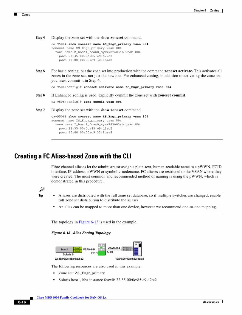
Chapter 6 Zoning Zones
Step 4 Display the zone set with the show zoneset command.
ca-9506# show zoneset name ZS_Engr_primary vsan 804zoneset name ZS_Engr_primary vsan 804 zone name Z_host1_fcaw0_symm78FA03ab vsan 804 pwwn 22:35:00:0c:85:e9:d2:c2 pwwn 10:00:00:00:c9:32:8b:a8
Step 5 For basic zoning, put the zone set into production with the command zoneset activate. This activates all zones in the zone set, not just the new one. For enhanced zoning, in addition to activating the zone set, you must commit it in Step 6.
ca-9506(config)# zoneset activate name ZS_Engr_primary vsan 804
Step 6 If Enhanced zoning is used, explicitly commit the zone set with zoneset commit.
ca-9506(config)# zone commit vsan 804
Step 7 Display the zone set with the show zoneset command.
ca-9506# show zoneset name ZS_Engr_primary vsan 804zoneset name ZS_Engr_primary vsan 804 zone name Z_host1_fcaw0_symm78FA03ab vsan 804 pwwn 22:35:00:0c:85:e9:d2:c2 pwwn 10:00:00:00:c9:32:8b:a8
Creating a FC Alias-based Zone with the CLIFibre channel aliases let the administrator assign a plain-text, human-readable name to a pWWN, FCID interface, IP-address, nWWN or symbolic-nodename. FC aliases are restricted to the VSAN where they were created. The most common and recommended method of naming is using the pWWN, which is demonstrated in this procedure.
Tip • Aliases are distributed with the full zone set database, so if multiple switches are changed, enable full zone set distribution to distribute the aliases.
• An alias can be mapped to more than one device, however we recommend one-to-one mapping.
The topology in Figure 6-13 is used in the example.
Figure 6-13 Alias Zoning Topology
The following resources are also used in this example:
• Zone set: ZS_Engr_primary
• Solaris host1, hba instance fcaw0: 22:35:00:0c:85:e9:d2:c2
6-16Cisco MDS 9000 Family Cookbook for SAN-OS 2.x
78-xxxxx-xx

Chapter 6 Zoning Zones
• Symmetrix 78, FA port 03ab: 10:00:00:00:c9:32:8b:a8
To create an FC alias-based zone, follow these steps:
Step 1 Create an FC alias-to-pWWN mapping for each FC alias, using the command member pwwn.
ca-9506# config terminalEnter configuration commands, one per line. End with CNTL/Z.ca-9506(config)# fcalias name host1_fcaw0 vsan 804ca-9506(config-fcalias)# member pwwn 22:35:00:0c:85:e9:d2:c2ca-9506(config-fcalias)# exitca-9506(config)# fcalias name symm78_fa03ab vsan 804ca-9506(config-fcalias)# member pwwn 10:00:00:00:c9:32:8b:a8ca-9506(config-fcalias)# end
Step 2 Display the newly created FC aliases with the command show fcalias.
ca-9506# show fcalias vsan 804fcalias name host1_fcaw0 vsan 804 pwwn 22:35:00:0c:85:e9:d2:c2
fcalias name symm78_fa03ab vsan 804 pwwn 10:00:00:00:c9:32:8b:a8
Step 3 Create an alias-based zone in the zoneset with the zone name command. Add members to the zone using the command member fcalias and the names of the FC aliases.
ca-9506# config terminalEnter configuration commands, one per line. End with CNTL/Z.ca-9506(config)# zoneset name ZS_Engr_primary vsan 804ca-9506(config-zoneset)# zone name Z_host1_fcaw0_symm78FA03abca-9506(config-zoneset-zone)# member fcalias host1_fcaw0ca-9506(config-zoneset-zone)# member fcalias symm78_fa03ab
Step 4 Optionally, display the zone set with the show zoneset command.
ca-9506# show zoneset vsan 804zoneset name ZS_Engr_primary vsan 804 zone name Z_host1_fcaw0_symm78FA03ab vsan 804 fcalias name host1_fcaw0 vsan 804 pwwn 22:35:00:0c:85:e9:d2:c2
fcalias name symm78_fa03ab vsan 804 pwwn 10:00:00:00:c9:32:8b:a8
Step 5 Activate the zone set with the command zoneset activate.
ca-9506# conf tEnter configuration commands, one per line. End with CNTL/Z.ca-9506(config)# zoneset activate name ZS_Engr_primary vsan 804Zoneset activation initiated. check zone status
Step 6 If enhanced zoning is enabled, commit the configuration with the zone commit command.
ca-9506(config)# zone commit vsan 804
6-17Cisco MDS 9000 Family Cookbook for SAN-OS 2.x
78-xxxxx-xx

Chapter 6 Zoning Zones
Creating an Interface-based Zone with the CLI This procedure creates a zone based upon the physical interface (fcX/Y) of the switch.The procedure is the same for both basic zoning and enhanced zoning with one exception. With enhanced zoning, the pending database must be committed at the end.
Tip Use interface-based zoning when a zone must be created before the hba is connected to the fabric. After the hba is connected to the fabric, convert the zone member to a pWWN-based member.
The topology in Figure 6-14 is used in the example.
Figure 6-14 Interface Zoning Topology
To create an interface-based zone with the CLI, follow these steps:
Step 1 Create the zone using the the zone name command. Add members with the member interface command.
ca-9506# config terminalEnter configuration commands, one per line. End with CNTL/Z.ca-9506(config)# zoneset name ZS_Engr_primary vsan 804ca-9506(config-zoneset)# zone name Z_host1_fcaw0_symm78FA03abca-9506(config-zoneset-zone)# member interface fc1/1ca-9506(config-zoneset-zone)# member interface fc1/2
Step 2 Optionally, display the zone set with the show zoneset command.
ca-9506# show zoneset vsan 804zoneset name ZS_Engr_primary vsan 804 zone name Z_host1_fcaw0_symm78FA03ab vsan 804 interface fc1/1 swwn 20:00:00:0c:85:e9:d2:c0 interface fc1/2 swwn 20:00:00:0c:85:e9:d2:c0
Note The sWWN is the switch WWN as displayed by the show wwn switch command:ca-9506# show wwn switch
Switch WWN is 20:00:00:0c:85:e9:d2:c0
Step 3 Activate the zone set with the command zoneset
ca-9506# conf tEnter configuration commands, one per line. End with CNTL/Z.ca-9506(config)# zoneset activate name ZS_Engr_primary vsan 804Zoneset activation initiated. check zone status
Step 4 If enhanced zoning is enabled, then commit the configuration.
ca-9506(config)# zone commit vsan 804
6-18Cisco MDS 9000 Family Cookbook for SAN-OS 2.x
78-xxxxx-xx

Cisco MDS 9078-xxxxx-xx
C H A P T E R 7
Inter-VSAN RoutingInter-VSAN Routing (IVR), first introduced into the MDS platform in SAN-OS version 1.3(1), provides the ability for devices in different VSANs to communicate. VSANs can then be created consisting of devices shared with other VSANs. The classic example is a shared tape library with many hosts in different VSANs. Another common implementation is allowing disk subsystems to communicate over WAN distances without having to merge large zone set databases.
The initial release of IVR (IVR-1) suffered from two deficiencies, although these issues were easily solved with planning. One, the first release required unique domain IDs in the source and destination VSANs. Second, the two VSANs could not have the same number. If you needed to merge two large fabrics and then IVR between them, duplicate VSAN IDs or domain IDs in the two fabrics caused problems.
IVR-2 continues to use the same basic principles as in IVR-1 such as IVR topologies, IVR zones and zone sets as well as transit VSANs. However, the deficiencies are resolved. Starting with SAN-OS version 2.1, IVR has the ability to perform Network Address Translation (NAT). IVR with FCNAT (IVR-2) solved both issues with IVR-1, eliminating the need for unique domain IDs and VSAN IDs.
In addition to the FCNAT capabilities, IVR also gained the ability to leverage CFS (introduced in SAN-OS 2.0(1)) and auto-topology (introduced in SAN-OS 2.1(1)). Although these two technologies make implementing IVR easier and faster, careful planning should still be done prior to configuration.
Tip The preferred method of configuring IVR either with or without NAT is with Cisco Fabric Services (CFS). This eases topology configuration and reduces the number of configuration steps and potential configuration errors. See IVR with CFS, page 7-8
7-100 Family Cookbook for SAN-OS 2.x
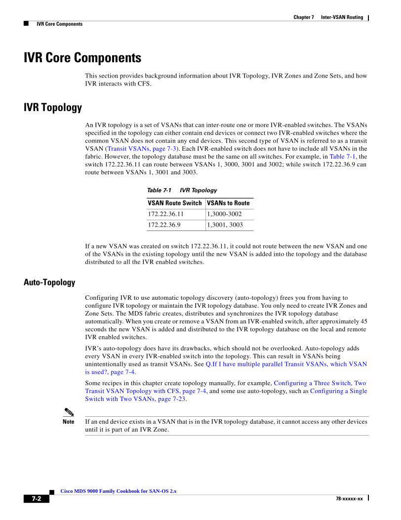
Chapter 7 Inter-VSAN Routing IVR Core Components
IVR Core ComponentsThis section provides background information about IVR Topology, IVR Zones and Zone Sets, and how IVR interacts with CFS.
IVR TopologyAn IVR topology is a set of VSANs that can inter-route one or more IVR-enabled switches. The VSANs specified in the topology can either contain end devices or connect two IVR-enabled switches where the common VSAN does not contain any end devices. This second type of VSAN is referred to as a transit VSAN (Transit VSANs, page 7-3). Each IVR-enabled switch does not have to include all VSANs in the fabric. However, the topology database must be the same on all switches. For example, in Table 7-1, the switch 172.22.36.11 can route between VSANs 1, 3000, 3001 and 3002; while switch 172.22.36.9 can route between VSANs 1, 3001 and 3003.
Table 7-1 IVR Topology
If a new VSAN was created on switch 172.22.36.11, it could not route between the new VSAN and one of the VSANs in the existing topology until the new VSAN is added into the topology and the database distributed to all the IVR enabled switches.
Auto-Topology
Configuring IVR to use automatic topology discovery (auto-topology) frees you from having to configure IVR topology or maintain the IVR topology database. You only need to create IVR Zones and Zone Sets. The MDS fabric creates, distributes and synchronizes the IVR topology database automatically. When you create or remove a VSAN from an IVR-enabled switch, after approximately 45 seconds the new VSAN is added and distributed to the IVR topology database on the local and remote IVR enabled switches.
IVR’s auto-topology does have its drawbacks, which should not be overlooked. Auto-topology adds every VSAN in every IVR-enabled switch into the topology. This can result in VSANs being unintentionally used as transit VSANs. See Q.If I have multiple parallel Transit VSANs, which VSAN is used?, page 7-4.
Some recipes in this chapter create topology manually, for example, Configuring a Three Switch, Two Transit VSAN Topology with CFS, page 7-4, and some use auto-topology, such as Configuring a Single Switch with Two VSANs, page 7-23.
Note If an end device exists in a VSAN that is in the IVR topology database, it cannot access any other devices until it is part of an IVR Zone.
VSAN Route Switch VSANs to Route
172.22.36.11 1,3000-3002
172.22.36.9 1,3001, 3003
7-2Cisco MDS 9000 Family Cookbook for SAN-OS 2.x
78-xxxxx-xx

Chapter 7 Inter-VSAN Routing IVR Core Components
Transit VSANs
When creating an IVR configuration, you may need to specify VSANs in addition to the source and destination VSANs. VSANs that do not necessarily contain any actual end devices may be required in the IVR topology. These VSANs are known as Transit VSANs and their sole purpose is connecting two VSANs together when no one switch contains both the source and destination VSAN. The most common example for using a Transit VSAN is to configure only the Transit VSAN to span a WAN link and not extend either the source or destination VSANs across the WAN.
In the example below, VSANs 1 and 3001 are potentially being used as a Transit VSAN. These two VSANs are the only common VSANs between the two MDS switches, so they can and will be used as Transit VSANs. (The IVR topology in Figure 7-1 corresponds to the information in Table 7-2.)
Table 7-2 IVR Topology
Figure 7-1 Example Topology using a Transit VSAN
To specify a particular VSAN as a Transit VSAN, no special configuration is required. The VSAN only needs to be part of the IVR topology to be used. It does not need to be empty, nor does it need to be in any specific Interop mode. It can have a mix of E and TE ports and can potentially contain non-MDS switches.
VSAN Route Switch VSANs to Route
172.22.36.11 1,3000-3002
172.22.36.9 1,3001, 3003
7-3Cisco MDS 9000 Family Cookbook for SAN-OS 2.x
78-xxxxx-xx

Chapter 7 Inter-VSAN Routing IVR Core Components
Note
Q. If I have multiple parallel Transit VSANs, which VSAN is used?
A. The most direct path is used, that is, the path that uses the fewest VSAN hops. For example, a path that requires a frame to go through two different Transit VSANs to reach the destination VSAN will not be chosen if there is a path that only requires one VSAN. This applies regardless of the FSPF cost of the links inside the VSANs.
If there happen to be two VSANs that have the same VSAN hop count (VSANs 1 and 3001 in Figure 7-1) then the one with the lowest VSAN ID is used. Therefore, in the Figure 7-1 example, VSAN 1 would be used as the Transit VSAN to go from VSAN 3002 to VSAN 3003.
IVR does not load balance across Transit VSANs, so IVR would use only VSAN 1 as the Transit, unless VSAN 1 failed or became isolated.
Tip • Only allow the VSAN you use as the Transit VSAN to be trunked across the ISL.
• Leverage multiple paths within the Transit VSAN as port-channels and use FSPF to route around path failures.
Configuring a Three Switch, Two Transit VSAN Topology with CFS
This recipe configures the IVR topology for a configuration with three IVR switches using two transit VSANs (see Figure 7-2). The example uses CFS to distribute the topology. IVR has already been enabled on all three switches. This procedure can be used for IVR-1 or IVR-2 with FC-NAT.
Tip Instead of using multiple transit VSANs, use a single transit VSAN extended over multiple switches. It simplifies the topology while providing the isolation of a transit VSAN.
Figure 7-2 Three Switch, Dual Transit VSAN IVR Topology.
7-4Cisco MDS 9000 Family Cookbook for SAN-OS 2.x
78-xxxxx-xx
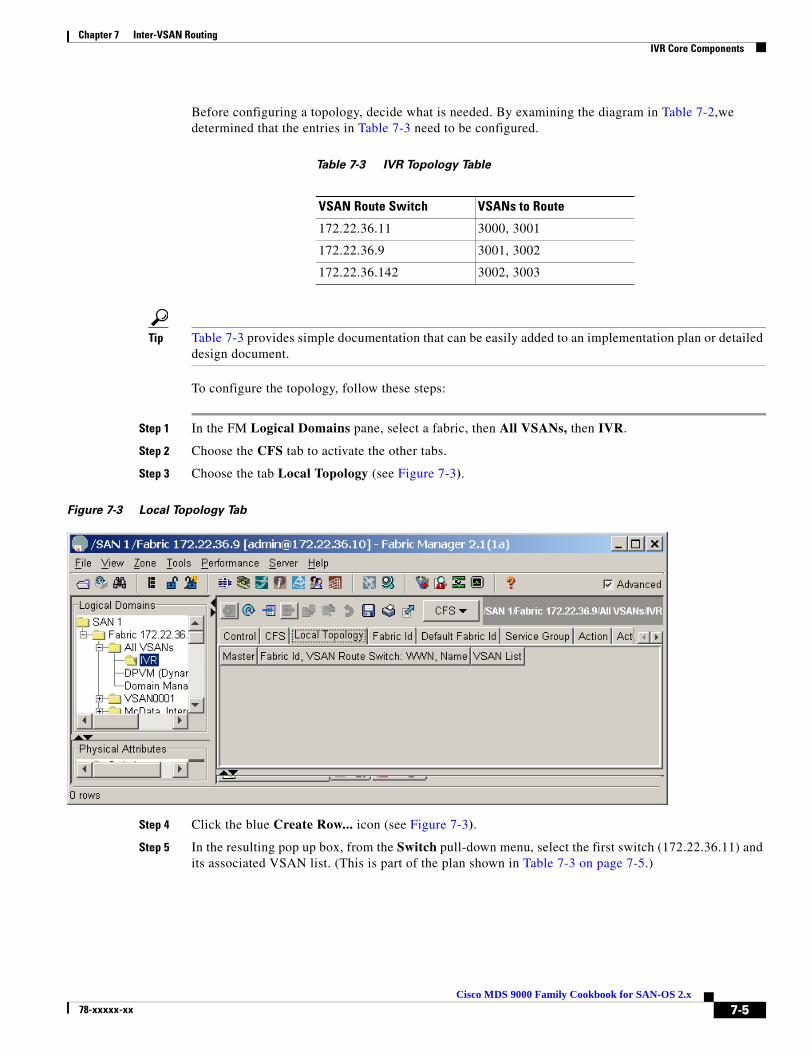
Chapter 7 Inter-VSAN Routing IVR Core Components
Before configuring a topology, decide what is needed. By examining the diagram in Table 7-2,we determined that the entries in Table 7-3 need to be configured.
Table 7-3 IVR Topology Table
Tip Table 7-3 provides simple documentation that can be easily added to an implementation plan or detailed design document.
To configure the topology, follow these steps:
Step 1 In the FM Logical Domains pane, select a fabric, then All VSANs, then IVR.
Step 2 Choose the CFS tab to activate the other tabs.
Step 3 Choose the tab Local Topology (see Figure 7-3).
Figure 7-3 Local Topology Tab
Step 4 Click the blue Create Row... icon (see Figure 7-3).
Step 5 In the resulting pop up box, from the Switch pull-down menu, select the first switch (172.22.36.11) and its associated VSAN list. (This is part of the plan shown in Table 7-3 on page 7-5.)
VSAN Route Switch VSANs to Route
172.22.36.11 3000, 3001
172.22.36.9 3001, 3002
172.22.36.142 3002, 3003
7-5Cisco MDS 9000 Family Cookbook for SAN-OS 2.x
78-xxxxx-xx

Chapter 7 Inter-VSAN Routing IVR Core Components
Step 6 Complete the switch’s VSAN List (3000, 3001) as shown in Figure 7-4.
Figure 7-4 Create Topology
Step 7 Click Create.
Step 8 Repeat this procedure for the second and third switch in Table 7-3 on page 7-5, then close the dialog box. The local topology should look like the one in Figure 7-5.
Figure 7-5 Local Topology
Step 9 Choose the Action tab.
Step 10 Check the Activate Local checkbox, then click the green Apply Changes icon.
Step 11 From the CFS pull-down menu, choose Commit. The message CFS(ivr):Committed appears in the bottom left corner of Fabric Manager.
7-6Cisco MDS 9000 Family Cookbook for SAN-OS 2.x
78-xxxxx-xx

Chapter 7 Inter-VSAN Routing IVR Core Components
Step 12 To verify the topology, choose the Active Topology tab. You see the topology in Figure 7-6.
Figure 7-6 Active Topology
At this point, the topology is correctly defined and the active topology contains the correct information. When this topology is configured and distributed by CFS, the Discrepancies tab will have no entries.
Now IVR zone sets can be defined to provide connectivity between the two end devices.
IVR Zones and Zone SetsIVR zones and zone sets, the objects that allow an end device in one VSAN to communicate with an end device in another VSAN, have the same features and functionality as a regular zone or zone set with one exception: the zone members are in different VSANs.
Members of IVR zones can be pWWNs or device aliases. RSCNs are restricted to the device within the IVR zone that triggered the RSCN. IVR zone names automatically have the prefix “IVRZ_” so they are easily identified in an active zone set.
switch# show zoneset active vsan 3000zoneset name ZoneSet1 vsan 3000zone name Zone1 vsan 3000 pwwn 50:06:0e:80:03:4e:95:23 [HDS20117-c20-9] pwwn 21:00:00:e0:8b:09:78:88 [ca-aix_lpfc0]zone name IVRZ_IvrZone1 vsan 3000 pwwn 50:06:0e:80:03:4e:95:23 [HDS20117-c20-9] pwwn 21:00:00:e0:8b:09:78:47 [ca-sun2_qlc0]
IVR zones must be members of IVR zone sets just as regular zones must be members of regular zone sets. An IVR zone set must also be activated in order to be part of the running configuration. There is still only one active zone set at activation, comprised of regular zones and IVR zones, so a switch that is not IVR- enabled (either a non-IVR enabled MDS or a third party switch) can still receive and apply the new active zone set.
7-7Cisco MDS 9000 Family Cookbook for SAN-OS 2.x
78-xxxxx-xx

Chapter 7 Inter-VSAN Routing IVR Core Components
Tip • If there are devices in the VSAN that require IVR access, the IVR-enabled switch should be used for all zoning, including non-IVR zoning, because the resulting active zone set is a union of the regular zone set and the IVR zone set.
• Do not use IVR zones to provide access between devices in the same VSAN. Use regular zones.
• Do not use regular zones to provide access between a real device and the pseudo device created by IVR. Use IVR zones.
• Both VSANs referenced in an IVR zone must be in the IVR topology to communicate.
IVR with CFSPrior to SAN-OS version 2.X, IVR topology had to be defined on each switch using either FM or the CLI. If a new switch was going to perform IVR, the entire IVR topology had to be manually entered on the new switch, then the other switches each had to be modified to include the new switch. For example, with the old method, a fabric with three switches required nine entries into the topology database (3 switches with IVR * 3 VSAN route switches).
Figure 7-7 is an example of a two-switch topology configuration without CFS. There are 2 switches with IVR times two VSAN route switches for a total of four entries.
Figure 7-7 IVR Topology without CFS
Modifying a topology is still a manual operation, but you no longer need to modify each switch individually. With the introduction of CFS support for IVR, a single topology is maintained and CFS distributes changes to other IVR switches in the fabric. If a new switch is added to the fabric, CFS automatically synchronizes the new switch with the existing IVR topology.
7-8Cisco MDS 9000 Family Cookbook for SAN-OS 2.x
78-xxxxx-xx

Chapter 7 Inter-VSAN Routing IVR Core Components
The topology described in Figure 7-7 is illustrated in Figure 7-8 and shown again, using CFS this time, in Figure 7-9.
Figure 7-8 CFS Reference Topology
The two-switch configuration with CFS has one row for each VSAN Route Switch as shown in Figure 7-9.
Figure 7-9 IVR Topology with CFS
The topology using CFS is easier to comprehend, since only one row per IVR-enabled switch is displayed. The first column represents the switch that FM will use to perform CFS operations. Columns two and three describe the routes. 172.22.36.11 routes between VSANs 1, 3000-3002, while switch 172.22.36.9 routes between 1, 3001 and 3003. CFS prevents duplicate information from being displayed as the topology is managed on a fabric basis rather than a per switch basis.
Note • If CFS is to be used with IVR, all IVR enabled switches must have CFS distribution for IVR enabled.
• Conversely, If CFS is not going to be used for IVR, then all of the IVR enabled switches should have CFS distribution for IVR disabled.
7-9Cisco MDS 9000 Family Cookbook for SAN-OS 2.x
78-xxxxx-xx

Chapter 7 Inter-VSAN Routing IVR-1
IVR-1The IVR-1 method of Inter-VSAN Routing has existed since SAN-OS 1.3 and does not do any Network Address Translation (NAT) functions. It requires unique VSAN and domain IDs across the IVR topology.
IVR-1 can use CFS for configuration distribution and application locking. Although IVR-1 can be used without CFS, the recipes in this chapter use CFS.
IVR-1 is first enabled, then configured.
Note IVR-1 requires that unique Domain IDs be used throughout the IVR topology.
Enabling IVR-1IVR-1 must be first enabled, then configured. Enabling IVR-1 can be done either from the CLI or with Fabric Manager. Use the same method (CLI or Fabric Manager) to enable all switches acting as border switches or all switches that route frames between VSANs. Enabling CFS must also be consistent; either all IVR switches in a fabric have CFS enabled for IVR, or none of them do.
Enabling IVR-1 with the CLI
To enable switches for IVR-1 from the command line, follow these steps:
Step 1 Enter configure terminal mode and enable IVR with the command ivr enable.
172.22.36.11# conf terminalEnter configuration commands, one per line. End with CNTL/Z.172.22.36.11(config)# ivr enable
Step 2 By default, CFS is not enabled with IVR-1, so enable CFS distribution. Notice that the scope is physical as IVR crosses VSANs.
172.22.36.11(config)# ivr distribute172.22.36.11(config)# do show cfs application name ivr
Enabled : Yes Timeout : 30s Merge Capable : Yes Scope : Physical
Step 3 Verify that all the switches are recognized by IVR using the command show CFS peers name ivr.
172.22.36.11# show cfs peers name ivr
Scope : Physical-------------------------------------------------- Switch WWN IP Address-------------------------------------------------- 20:00:00:05:30:00:68:5e 172.22.36.11 [Local]
Total number of entries = 1
7-10Cisco MDS 9000 Family Cookbook for SAN-OS 2.x
78-xxxxx-xx
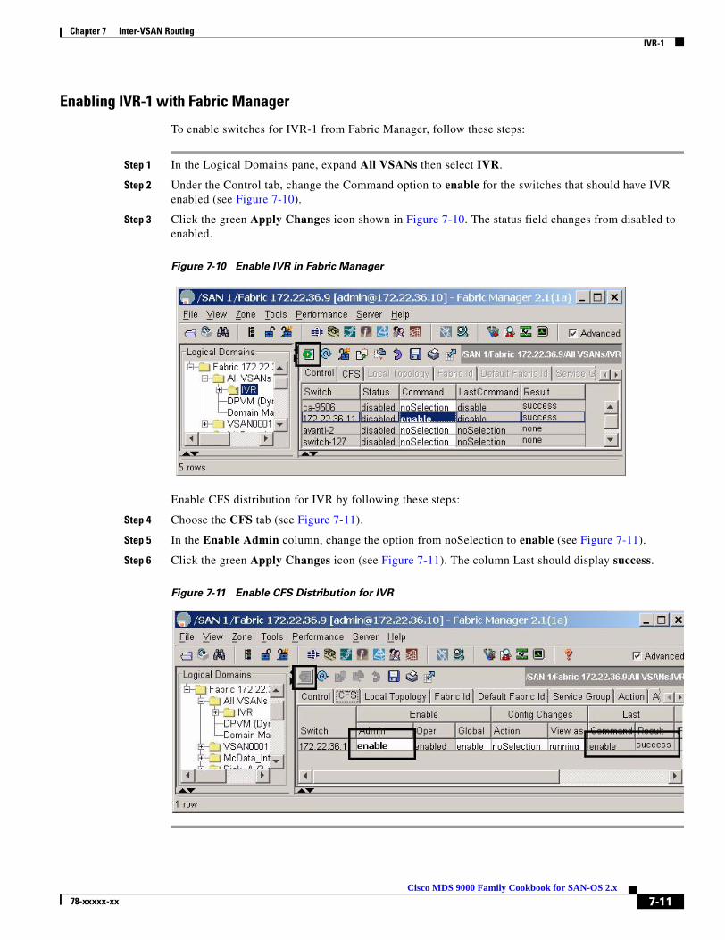
Chapter 7 Inter-VSAN Routing IVR-1
Enabling IVR-1 with Fabric Manager
To enable switches for IVR-1 from Fabric Manager, follow these steps:
Step 1 In the Logical Domains pane, expand All VSANs then select IVR.
Step 2 Under the Control tab, change the Command option to enable for the switches that should have IVR enabled (see Figure 7-10).
Step 3 Click the green Apply Changes icon shown in Figure 7-10. The status field changes from disabled to enabled.
Figure 7-10 Enable IVR in Fabric Manager
Enable CFS distribution for IVR by following these steps:
Step 4 Choose the CFS tab (see Figure 7-11).
Step 5 In the Enable Admin column, change the option from noSelection to enable (see Figure 7-11).
Step 6 Click the green Apply Changes icon (see Figure 7-11). The column Last should display success.
Figure 7-11 Enable CFS Distribution for IVR
7-11Cisco MDS 9000 Family Cookbook for SAN-OS 2.x
78-xxxxx-xx

Chapter 7 Inter-VSAN Routing IVR-1
Configuring a Single Switch and Two VSANsIn this recipe, the most basic IVR environment is configured with Fabric Manager. This environment has one MDS switch and two VSANs (see Figure 7-12). CFS is used.
Figure 7-12 Single Switch IVR-1, Two VSAN Topology
Creating the IVR Topology
Create the IVR topology from Fabric Manager by following these steps:
Step 1 Enable IVR as described in Enabling IVR-1, page 7-10.
Step 2 In the Fabric Manager Logical Domains window, choose the fabric, expand All VSANs and select IVR.
Step 3 In the Local Topology tab, click the Create Row... button.
Step 4 In the VSAN list (see Figure 7-13) enter the VSANs to be routed (3000,3002).
Step 5 Expand the Switch List and choose a switch (see Figure 7-13).
Step 6 Click Create. The word success should be displayed in the bottom of the window.
Step 7 Close the window in Figure 7-13.
Figure 7-13 Single Switch IVR-1 Create Topology
To activate the topology from Fabric Manager, follow these steps:
Step 8 Choose the Action tab.
Step 9 Check the Activate Local checkbox.
7-12Cisco MDS 9000 Family Cookbook for SAN-OS 2.x
78-xxxxx-xx

Chapter 7 Inter-VSAN Routing IVR-1
Step 10 Click the green Apply Changes icon. Note that the topology is not active until it has been CFS committed (follow the next steps).
To CFS commit the topology from Fabric Manager, follow these steps:
Step 11 From the CFS pull-down menu choose Commit.
In the bottom left hand corner of FM, the message CFS(ivr):Committed should be displayed. Also, the Active Topology tab contents should match those of the Local Topology tab.
The next phase is to create the IVR zone set and accompanying zones
Creating the IVR Zone Set and Zones
To create the IVR zone set and accompanying zones from Fabric Manager, follow these steps:
Step 1 In the Logical Domains pane, select the fabric, expand All VSANs, then right-click IVR (see Figure 7-14).
Step 2 Choose Edit Local Full Zone Database.
Step 3 In the resulting dialog, create an IVR zone set by right-clicking Zonesets and choosing Insert.
Step 4 Enter a name for the zone set and click OK. The resulting zone set appears in the left pane.
Step 5 Create the IVR Zone by right- clicking Zones in the left pane and choosing Insert.
Step 6 Enter a meaningful zone name and click OK.
Step 7 Drag devices to be zoned from the bottom pane into the newly created zone in the top pane of the screen (see Figure 7-14).
7-13Cisco MDS 9000 Family Cookbook for SAN-OS 2.x
78-xxxxx-xx
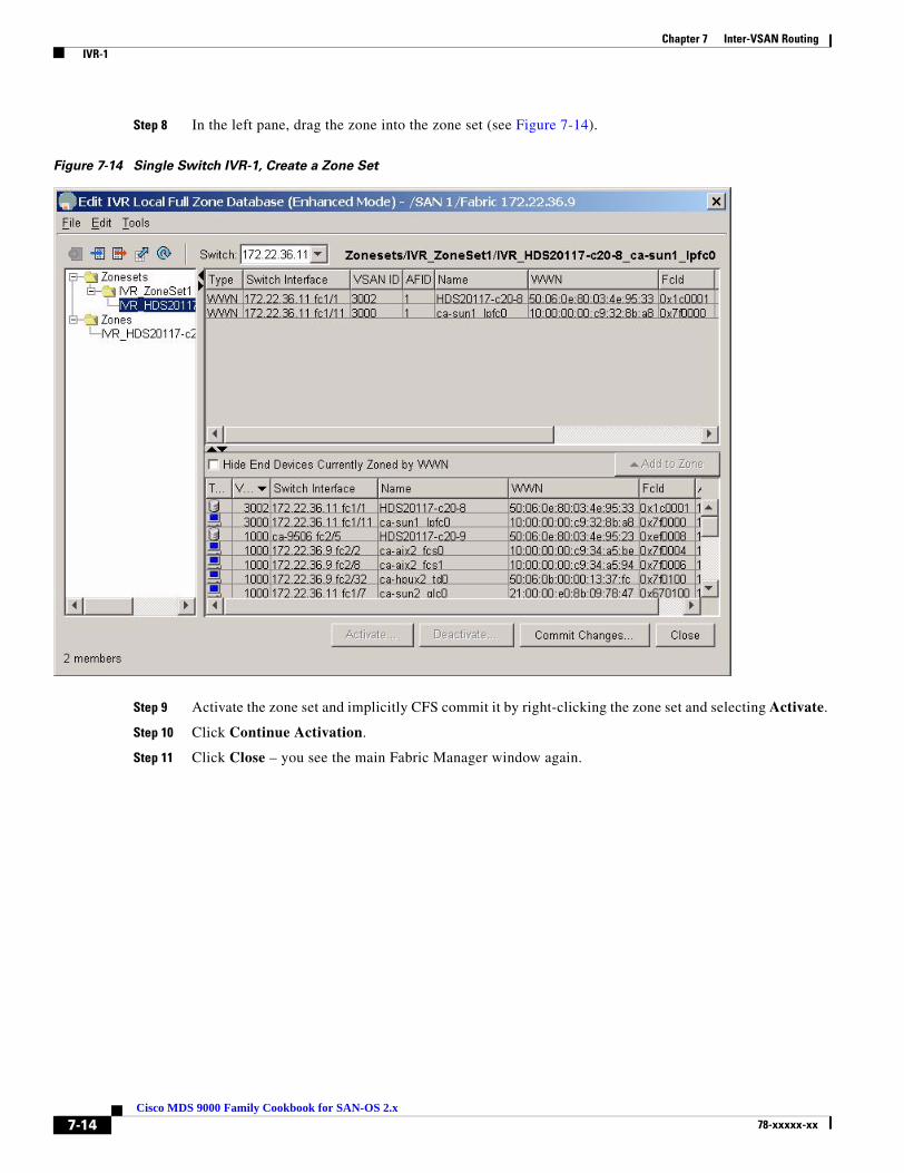
Chapter 7 Inter-VSAN Routing IVR-1
Step 8 In the left pane, drag the zone into the zone set (see Figure 7-14).
Figure 7-14 Single Switch IVR-1, Create a Zone Set
Step 9 Activate the zone set and implicitly CFS commit it by right-clicking the zone set and selecting Activate.
Step 10 Click Continue Activation.
Step 11 Click Close – you see the main Fabric Manager window again.
7-14Cisco MDS 9000 Family Cookbook for SAN-OS 2.x
78-xxxxx-xx

Chapter 7 Inter-VSAN Routing IVR-1
Step 12 Display the map of IVR members by selecting the IVR Zone in the Logical Domains pane (see Figure 7-15).
Figure 7-15 Single Switch IVR-1, Display IVR Zone Set
7-15Cisco MDS 9000 Family Cookbook for SAN-OS 2.x
78-xxxxx-xx

Chapter 7 Inter-VSAN Routing IVR-2 with FC-NAT
IVR-2 with FC-NATIn SAN-OS version 2.1(1a), Cisco introduced IVR with Fibre Channel Network Address Translation (NAT). NAT provides the ability to:
• Route between fabrics containing duplicate domain IDs.
• Route between VSANs.
• Route between two VSANs of the same VSAN ID.
In addition, instead of representing each native VSAN domain with a unique virtual domain, a single virtual domain represents all of the domains in the native VSAN. Finally, IVR-FCNAT, leveraging the CFS infrastructure, automatically discovers topology, thus alleviating the process of configuring and maintaining IVR topology.
Enabling IVR-2This recipe uses Fabric Manager to enable IVR-2 with CFS and auto-topology discovery.
Note In a multi-switch topology, repeat these steps for each switch in the fabric. Remember, that CFS commands (for example, adding NAT and auto-topology) only have to be done from one switch as CFS informs the other switches.
To enable IVR-2 with CFS and auto-topology discovery, follow these steps:
Step 1 In the Logical Domains pane, expand All VSANs, then select IVR as shown in Figure 7-16.
Step 2 Under the Control tab, change the Command column entry to enable for switches that should have IVR enabled.
Step 3 Click the green Apply Changes icon shown in Figure 7-16.
The Status field entries change from disabled to enabled for the switches you selected in Step 2.
Figure 7-16 Enable IVR in Fabric Manager
7-16Cisco MDS 9000 Family Cookbook for SAN-OS 2.x
78-xxxxx-xx
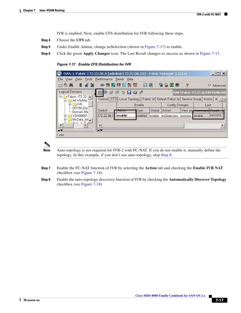
Chapter 7 Inter-VSAN Routing IVR-2 with FC-NAT
IVR is enabled. Next, enable CFS distribution for IVR following these steps.
Step 4 Choose the CFS tab.
Step 5 Under Enable Admin, change noSelection (shown in Figure 7-17) to enable.
Step 6 Click the green Apply Changes icon. The Last Result changes to success as shown in Figure 7-17.
Figure 7-17 Enable CFS Distribution for IVR
Note Auto-topology is not required for IVR-2 with FC-NAT. If you do not enable it, manually define the topology. In this example, if you don’t use auto-topology, skip Step 8.
Step 7 Enable the FC-NAT function of IVR by selecting the Action tab and checking the Enable IVR NAT checkbox (see Figure 7-18).
Step 8 Enable the auto-topology discovery function of IVR by checking the Automatically Discover Topology checkbox (see Figure 7-18)
7-17Cisco MDS 9000 Family Cookbook for SAN-OS 2.x
78-xxxxx-xx
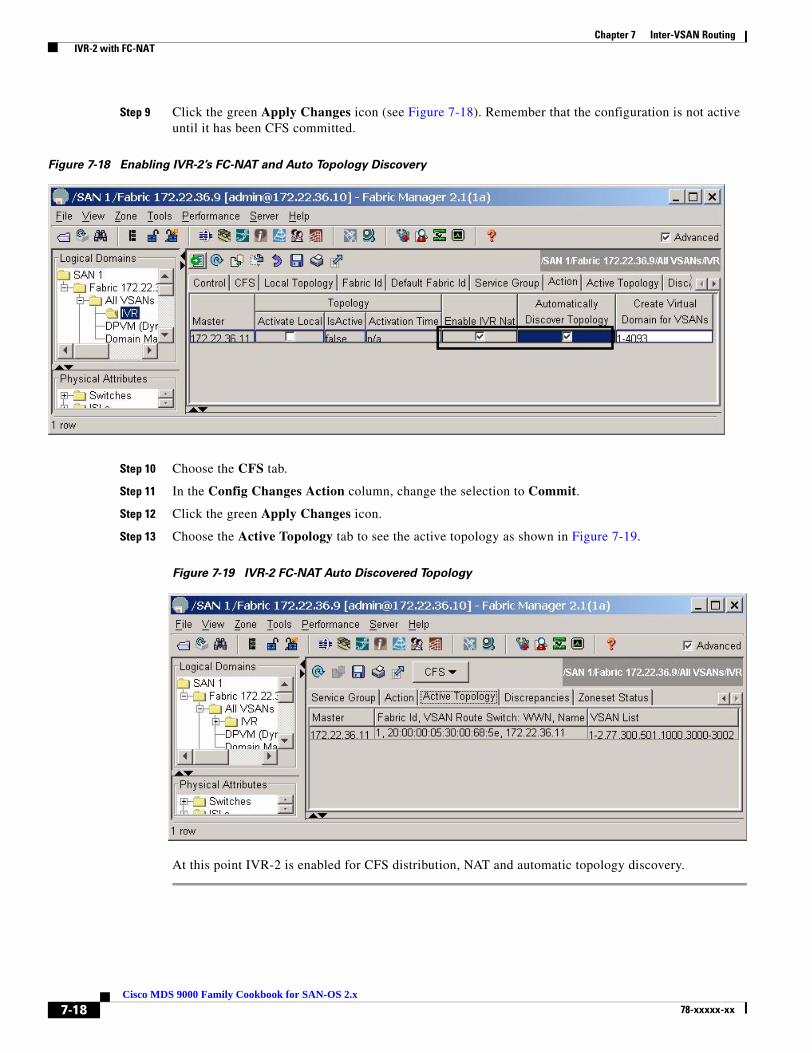
Chapter 7 Inter-VSAN Routing IVR-2 with FC-NAT
Step 9 Click the green Apply Changes icon (see Figure 7-18). Remember that the configuration is not active until it has been CFS committed.
Figure 7-18 Enabling IVR-2’s FC-NAT and Auto Topology Discovery
Step 10 Choose the CFS tab.
Step 11 In the Config Changes Action column, change the selection to Commit.
Step 12 Click the green Apply Changes icon.
Step 13 Choose the Active Topology tab to see the active topology as shown in Figure 7-19.
Figure 7-19 IVR-2 FC-NAT Auto Discovered Topology
At this point IVR-2 is enabled for CFS distribution, NAT and automatic topology discovery.
7-18Cisco MDS 9000 Family Cookbook for SAN-OS 2.x
78-xxxxx-xx

Chapter 7 Inter-VSAN Routing IVR-2 with FC-NAT
Upgrading from IVR-1 to IVR-2This recipe upgrades an IVR-1 configuration to IVR-2 using both CFS and auto-topology.
Caution Upgrading from IVR-1 to IVR-2 disrupts IVR-based traffic, but does not disrupt non-IVR traffic such as non-IVR zones contained in a VSAN.
Upgrading from IVR-1 to IVR-2 with NAT may change the FC IDs of virtual devices, thus requiring FC ID dependant hosts such as HPUX and AIX to re-scan for the devices.
Note IVR-1 cannot coexist with IVR-2 within a single physical fabric. Border switches running IVR must be either in IVR-1 mode or IVR-2 mode. Mixed configurations are not supported. Use CFS to make sure all switches are running the same configuration.
To upgrade an IVR-1 configuration to IVR-2 using both CFS and auto-topology, follow these steps:
Step 1 Back up all MDS switch configurations using a procedure similar to Copying Files to and from a Switch, page 1-16.
Step 2 Upgrade all IVR border switches to SAN-OS 2.1(1a) or later, as IVR-2 with FC-NAT was first introduced in SAN-OS 2.1(1a). Switches not acting as IVR border switches are not required to be upgraded, but we recommended that you upgrade them. For upgrading SAN-OS firmware directions, see Firmware Upgrades and Downgrades, page 1-20.
Step 3 Deactivate the IVR zone set using Fabric Manager. This does not delete the IVR zone set from the local database as it is reactivated once IVR-2 has been enabled.
a. In the Logical Domains pane, select a fabric and expand All VSANs.
b. Right-click IVR and choose Deactivate Zoneset. A pop-up window opens.
c. Click OK.
All devices are now isolated from devices in other VSANs.
d. Close the pop-up window.
7-19Cisco MDS 9000 Family Cookbook for SAN-OS 2.x
78-xxxxx-xx
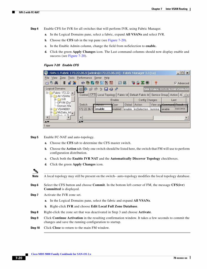
Chapter 7 Inter-VSAN Routing IVR-2 with FC-NAT
Step 4 Enable CFS for IVR for all switches that will perform IVR, using Fabric Manager.
a. In the Logical Domains pane, select a fabric, expand All VSANs and select IVR.
b. Choose the CFS tab in the top pane (see Figure 7-20).
c. In the Enable Admin column, change the field from noSelection to enable.
d. Click the green Apply Changes icon. The Last command columns should now display enable and success (see Figure 7-20).
Figure 7-20 Enable CFS
Step 5 Enable FC-NAT and auto-topology.
a. Choose the CFS tab to determine the CFS master switch.
b. Choose the Action tab. Only one switch should be listed here, the switch that FM will use to perform configuration distribution.
c. Check both the Enable IVR NAT and the Automatically Discover Topology checkboxes.
d. Click the green Apply Changes icon.
Note A local topology may still be present on the switch– auto-topology modifies the local topology database.
Step 6 Select the CFS button and choose Commit. In the bottom left corner of FM, the message CFS(ivr) Committed is displayed.
Step 7 Activate the IVR zone set.
a. In the Logical Domains pane, select the fabric and expand All VSANs.
b. Right-click IVR and choose Edit Local Full Zone Database.
Step 8 Right-click the zone set that was deactivated in Step 3 and choose Activate.
Step 9 Click Continue Activation in the resulting confirmation window. It takes a few seconds to commit the changes and save the running-configuration to startup.
Step 10 Click Close to return to the main FM window.
7-20Cisco MDS 9000 Family Cookbook for SAN-OS 2.x
78-xxxxx-xx
Chapter 7 Inter-VSAN Routing IVR-2 with FC-NAT
At this point the switches are upgraded to IVR-2 with FC-NAT, CFS and auto-topology. HPUX and AIX hosts with disks tied to the FC ID may need to re-scan for the new FC IDs.
Configuring Persistent FC IDs in IVRStarting with SAN-OS version 2.1(2), virtual devices created by an IVR with NAT configuration can have associated persistent FC IDs. This feature, similar to the persistent FC ID feature discussed in Chapter 5, “VSANs” for actual devices, enables a virtual device to receive the same FC ID across reboots of the switch.
Tip HPUX and AIX are two operating systems that use FC IDs in device paths to storage. If the FC ID changes for a device accessed by either an AIX or a HPUX host, the host may lose access to the device. Configure persistent FC IDs for IVR to have a switch assign the same FC ID to a virtual device across switch reboots.
This example configures a storage device to use a specific FC ID in the host’s VSAN. The actual devices are already logged into the fabric and the IVR topology has been created to include VSANs 3000 and 3002. In addition, this infomation applies to the example:
• IVR Features Enabled: CFS and IVR with NAT
• Host with pWWN: 10:00:00:00:c9:32:8b:a8 and VSAN 3002
• Storage with pWWN: 50:06:0e:80:03:4e:95:33, VSAN 3000, Real FC ID: 0xef0002, and FC ID to be configured in Host VSAN: 0x630063
• IVR Topology:
AFID SWITCH WWN Active Cfg. VSANS-------------------------------------------------------------- 1 20:00:00:05:30:00:68:5e * yes yes 3000,3002
To configure a storage device to use a specific FC ID in the host VSAN, follow these steps:
Step 1 Enter IVR FC domain configuration mode for the AFID and VSAN for the location of the virtual device. In this case it’s the AFID and VSAN where the storage will be virtual.
switch# conf tswitch(config)# ivr fcdomain database autonomous-fabric-num 1 vsan 3002switch(config-fcdomain)#
Step 2 Enter the native AFID, VSAN of the storage device, and domain to be used in the host’s VSAN. CFS is enabled for IVR so any changes must be committed later. The domain ID in this command is in decimal format.
switch(config-fcdomain)# native-autonomous-fabric-num 1 native-vsan 3000 domain 99fabric is locked for configuration. Please commit after configuration is done.switch(config-fcdomain-fcid)#
Step 3 Specify the pWWN and FC ID to be used. (A device-alias can be used instead of a pWWN.) The virtual domain and FC IDs are not created until the zone set is activated.
switch(config-fcdomain-fcid)# pwwn 50:06:0e:80:03:4e:95:33 fcid 0x630063
The FCID should correspond to virtual domain 99 specified earlier for this modeswitch(config-fcdomain-fcid)#
7-21Cisco MDS 9000 Family Cookbook for SAN-OS 2.x
78-xxxxx-xx

Chapter 7 Inter-VSAN Routing IVR-2 with FC-NAT
Step 4 Create the IVR zone sets and zones with ivr zoneset commands.
switch(config-fcdomain-fcid# ivr zoneset name IVR_Zoneset1switch(config-ivr-zoneset)# zone name IVRZ_host1_lpfc0_Array1_port12switch(config-ivr-zoneset-zone)# member pwwn 10:00:00:00:c9:32:8b:a8 vsan 3002switch(config-ivr-zoneset-zone)# member pwwn 50:06:0e:80:03:4e:95:33 vsan 3000switch(config-ivr-zoneset-zone)# ivr zoneset activate name IVR_Zoneset1
Step 5 CFS commit the changes for IVR to activate both the IVR zone set and the modifications to the IVR persistent FC ID database.
switch(config)# ivr commitcommit initiated. check ivr status
Step 6 Verify FC IDs and active zone set with the show command.
switch(config)# do show ivr fcdomain database---------------------------------------------------- AFID Vsan Native-AFID Native-Vsan Virtual-domain---------------------------------------------------- 1 3002 1 3000 0x63(99)
Number of Virtual-domain entries: 1
---------------------------------------------------- AFID Vsan Pwwn Virtual-fcid---------------------------------------------------- 1 3002 50:06:0e:80:03:4e:95:33 0x630063 [HDS20117-c20-8]
Number of Virtual-fcid entries: 1
switch# show fcns database vsan 3002
VSAN 3002:--------------------------------------------------------------------------FCID TYPE PWWN (VENDOR) FC4-TYPE:FEATURE--------------------------------------------------------------------------0x1c0003 N 10:00:00:00:c9:32:8b:a8 (Emulex) scsi-fcp [ca-sun1_lpfc0]0x630063 N 50:06:0e:80:03:4e:95:33 scsi-fcp [HDS20117-c20-8]
Total number of entries = 2
switch# show zoneset active vsan 3002zoneset name ZS_test vsan 3002 zone name zone1 vsan 3002 pwwn 50:06:0e:80:03:4e:99:99 pwwn 50:06:0e:80:03:4e:98:98
zone name IVRZ_IVRZ_host1_lpfc0_Array1_port12 vsan 3002 * fcid 0x630063 [pwwn 50:06:0e:80:03:4e:95:33] [HDS20117-c20-8] * fcid 0x1c0003 [pwwn 10:00:00:00:c9:32:8b:a8] [ca-sun1_lpfc0]
7-22Cisco MDS 9000 Family Cookbook for SAN-OS 2.x
78-xxxxx-xx
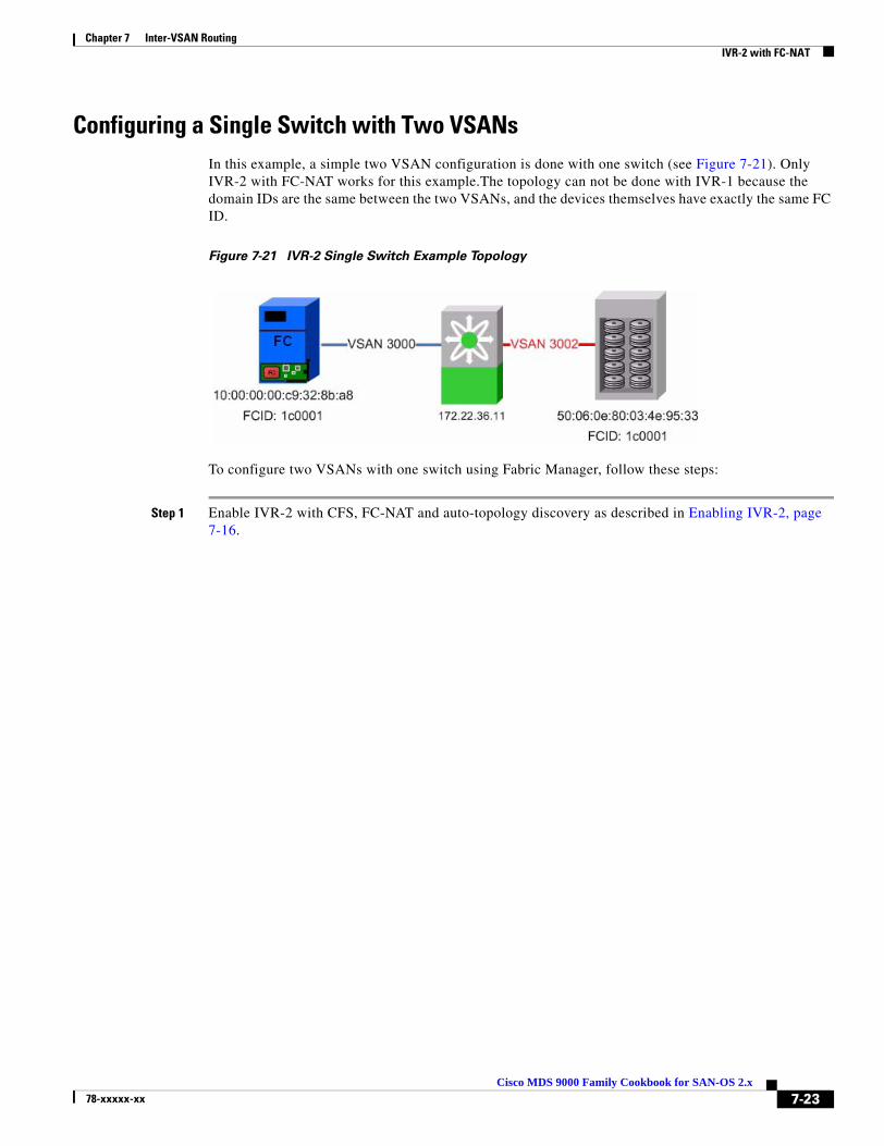
Chapter 7 Inter-VSAN Routing IVR-2 with FC-NAT
Configuring a Single Switch with Two VSANsIn this example, a simple two VSAN configuration is done with one switch (see Figure 7-21). Only IVR-2 with FC-NAT works for this example.The topology can not be done with IVR-1 because the domain IDs are the same between the two VSANs, and the devices themselves have exactly the same FC ID.
Figure 7-21 IVR-2 Single Switch Example Topology
To configure two VSANs with one switch using Fabric Manager, follow these steps:
Step 1 Enable IVR-2 with CFS, FC-NAT and auto-topology discovery as described in Enabling IVR-2, page 7-16.
7-23Cisco MDS 9000 Family Cookbook for SAN-OS 2.x
78-xxxxx-xx

Chapter 7 Inter-VSAN Routing IVR-2 with FC-NAT
Step 2 Create the IVR zones and zone set.
a. In the Logical Domains pane, select the fabric and expand All VSANs .
b. Right-click IVR and choose Edit Full Local Zone Database.
The resulting dialog box looks like the non-IVR zoning dialog box (see Figure 7-22).
Figure 7-22 IVR-2 Create a Zone Set
7-24Cisco MDS 9000 Family Cookbook for SAN-OS 2.x
78-xxxxx-xx

Chapter 7 Inter-VSAN Routing IVR-2 with FC-NAT
Step 3 Create the IVR zone set as shown in Figure 7-23.
a. Right-click Zonesets in the left pane and choose Insert.
b. Type a name for the zone set and click OK.
The resulting zone set appears in the left hand pane.
Step 4 Create the IVR zone as shown in Figure 7-23.
a. Right-click Zone in the left pane and choose Insert.
b. Enter a meaningful zone name and click OK.
Step 5 Add the members to be zoned from the bottom pane into the newly created zone by dragging them into the zone (see Figure 7-23).
Step 6 In the left pane, drag the zone into the zone set (see Figure 7-23).
Figure 7-23 Single Switch IVR-2, Create Zoneset
7-25Cisco MDS 9000 Family Cookbook for SAN-OS 2.x
78-xxxxx-xx

Chapter 7 Inter-VSAN Routing IVR-2 with FC-NAT
Step 7 Activate the zone set and implicitly CFS commit it (see Figure 7-24).
a. Right- click the zone set in the left pane and choose Activate.
b. Click Continue Activation.
c. Click Close to return to the main FM window.
Figure 7-24 Single Switch IVR-2, Display IVR Zoneset
At this point, the host ca-sun1 can access the storage on HDS20017-c20-8.
7-26Cisco MDS 9000 Family Cookbook for SAN-OS 2.x
78-xxxxx-xx
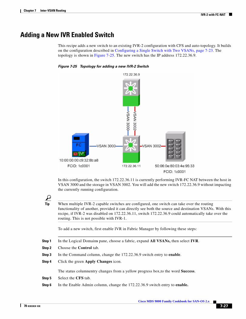
Chapter 7 Inter-VSAN Routing IVR-2 with FC-NAT
Adding a New IVR Enabled SwitchThis recipe adds a new switch to an existing IVR-2 configuration with CFS and auto-topology. It builds on the configuration described in Configuring a Single Switch with Two VSANs, page 7-23. The topology is shown in Figure 7-25. The new switch has the IP address 172.22.36.9.
Figure 7-25 Topology for adding a new IVR-2 Switch
In this configuration, the switch 172.22.36.11 is currently performing IVR-FC NAT between the host in VSAN 3000 and the storage in VSAN 3002. You will add the new switch 172.22.36.9 without impacting the currently running configuration.
Tip When multiple IVR-2 capable switches are configured, one switch can take over the routing functionality of another, provided it can directly see both the source and destination VSANs. With this recipe, if IVR-2 was disabled on 172.22.36.11, switch 172.22.36.9 could automatically take over the routing. This is not possible with IVR-1.
To add a new switch, first enable IVR in Fabric Manager by following these steps:
Step 1 In the Logical Domains pane, choose a fabric, expand All VSANs, then select IVR.
Step 2 Choose the Control tab.
Step 3 In the Command column, change the 172.22.36.9 switch entry to enable.
Step 4 Click the green Apply Changes icon.
The status columnentry changes from a yellow progress box,to the word Success.
Step 5 Select the CFS tab.
Step 6 In the Enable Admin column, change the 172.22.36.9 switch entry to enable.
7-27Cisco MDS 9000 Family Cookbook for SAN-OS 2.x
78-xxxxx-xx

Chapter 7 Inter-VSAN Routing IVR-2 with FC-NAT
Step 7 Click the green Apply Changes icon.
The Last Result column changes from inProgress to Success.
Step 8 Click the Active Topology column to see a topology that includes both switches, even though only the 172.22.36.11 switch is performing any IVR.
Step 9 Save the configuration of both switches
Note By having CFS already enabled on the first switch (172.22.36.11) and enabling IVR and CFS on the second switch (172.22.36.9) the second switch learned what configuration parameters (FC-NAT and auto-topology) to enable. Therefore, there was no need to enable FC-NAT and auto-topology on the second switch.
Tip One of the primary advantages of CFS is the fact that the configuration of the first switch was communicated to the second switch. This is more apparent when the first switch configuration is more complex. In addition, as the topology grows larger and the number of switches, devices and VSANs increase, adding a single switch to an N IVR-enabled configuration requires changes to be made to more and more switches, increasing the possibility for human error if done manually.
7-28Cisco MDS 9000 Family Cookbook for SAN-OS 2.x
78-xxxxx-xx

Cisco MDS 9078-xxxxx-xx
C H A P T E R 8
FCIPFCIP (Fibre Channel over IP) is an IETF standards-based protocol for connecting Fibre Channel SANs over IP networks. FCIP encapsulates the FCP frames in a TCP/IP packet which is then sent across an IP network. FCIP is used to interconnect geographically dispersed SANs using the IP backbone network. Simply put, FCIP creates an FC tunnel over an existing IP network. The MDS 9200 and 9500 series switches support FCIP using the IPS-8, IPS-4 and the 14+2 blades. This chapter’s recipes create and manage FCIP links between MDS switches.
Enabling FCIP Execute the FCIP enable command before attempting to configure FCIP on the switch.
Caution If you do not run the fcip enable command, you can not do any further FCIP configuration. This command enables FCIP configuration options in the CLI.
MDS1# conf tEnter configuration commands, one per line. End with CNTL/Z.MDS1(config)# FCIP enableMDS1(config)#^ZMDS1#
8-100 Family Cookbook for SAN-OS 2.x
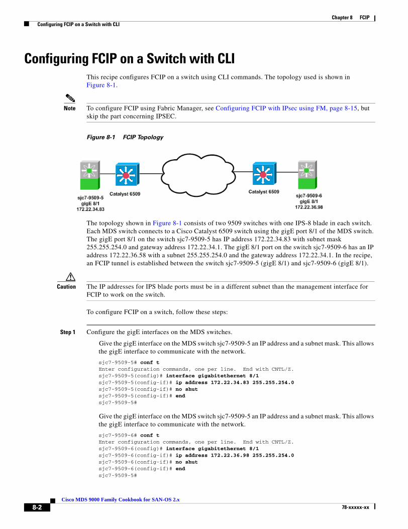
Chapter 8 FCIP Configuring FCIP on a Switch with CLI
Configuring FCIP on a Switch with CLIThis recipe configures FCIP on a switch using CLI commands. The topology used is shown in Figure 8-1.
Note To configure FCIP using Fabric Manager, see Configuring FCIP with IPsec using FM, page 8-15, but skip the part concerning IPSEC.
Figure 8-1 FCIP Topology
The topology shown in Figure 8-1 consists of two 9509 switches with one IPS-8 blade in each switch. Each MDS switch connects to a Cisco Catalyst 6509 switch using the gigE port 8/1 of the MDS switch. The gigE port 8/1 on the switch sjc7-9509-5 has IP address 172.22.34.83 with subnet mask 255.255.254.0 and gateway address 172.22.34.1. The gigE 8/1 port on the switch sjc7-9509-6 has an IP address 172.22.36.58 with a subnet 255.255.254.0 and the gateway address 172.22.34.1. In the recipe, an FCIP tunnel is established between the switch sjc7-9509-5 (gigE 8/1) and sjc7-9509-6 (gigE 8/1).
Caution The IP addresses for IPS blade ports must be in a different subnet than the management interface for FCIP to work on the switch.
To configure FCIP on a switch, follow these steps:
Step 1 Configure the gigE interfaces on the MDS switches.
Give the gigE interface on the MDS switch sjc7-9509-5 an IP address and a subnet mask. This allows the gigE interface to communicate with the network.
sjc7-9509-5# conf tEnter configuration commands, one per line. End with CNTL/Z.sjc7-9509-5(config)# interface gigabitethernet 8/1sjc7-9509-5(config-if)# ip address 172.22.34.83 255.255.254.0 sjc7-9509-5(config-if)# no shutsjc7-9509-5(config-if)# endsjc7-9509-5#
Give the gigE interface on the MDS switch sjc7-9509-5 an IP address and a subnet mask. This allows the gigE interface to communicate with the network.
sjc7-9509-6# conf tEnter configuration commands, one per line. End with CNTL/Z.sjc7-9509-6(config)# interface gigabitethernet 8/1sjc7-9509-6(config-if)# ip address 172.22.36.98 255.255.254.0 sjc7-9509-6(config-if)# no shutsjc7-9509-6(config-if)# endsjc7-9509-5#
8-2Cisco MDS 9000 Family Cookbook for SAN-OS 2.x
78-xxxxx-xx

Chapter 8 FCIP Configuring FCIP on a Switch with CLI
Step 2 Configure an IP route so that the two gigE interfaces can communicate.
An IP route needs to be configured to allow the two gigE ports on switches sjc7-9509-5 and sjc7-9509-6 to communicate. In this recipe, the gigE ports are in two different subnets, so they must have an explicit route for communication.
Note We recommend that you create a host route to each of the two gigE interfaces with a subnet mask of 255.255.255.255. This allows only the two gigE interfaces to communicate.
For the gigE port 8/1 on switch sjc7-9509-5 to communicate with the port gigE 8/1 on switch sjc7-9509-6, create this route configuration on switch sjc7-9509-5.
sjc7-9509-5# conf tEnter configuration commands, one per line. End with CNTL/Z.sjc7-9509-5(config)# ip route 172.22.36.98 255.255.255.255 172.22.34.1 interface gigabitethernet 8/1sjc7-9509-5(config)# endsjc7-9509-5#
The configuration above provides this information: In order to reach 172.22.36.98 use the gateway 172.22.34.1 and interface gigE 8/1 on switch sjc7-9509-5.
For the gigE port 8/1 on switch sjc7-9509-6 to communicate with gigE port 8/1 on switch sjc7-9509-5, create this similar route configuration on switch sjc7-9509-6.
sjc7-9509-6# conf tEnter configuration commands, one per line. End with CNTL/Z.sjc7-9509-6(config)# ip route 172.22.34.83 255.255.255.255 172.22.36.1 interface gigabitethernet 8/1sjc7-9509-6(config-if)# endsjc7-9509-6#
The configuration above provides this information: In order to reach 172.22.34.83 use the gateway 172.22.36.1 and interface gigE 8/1 on switch sjc7-9509-6.
8-3Cisco MDS 9000 Family Cookbook for SAN-OS 2.x
78-xxxxx-xx

Chapter 8 FCIP Configuring FCIP on a Switch with CLI
Step 3 Ping the gigE interfaces to ensure that the gigE ports can communicate with each other.
From the switch sjc7-9509-5 ping the IP address of the gigE interface 8/1 on switch sjc7-9509-6. Similarly, ping the IP address of the gigE interface 8/1 on switch sjc7-9509-5 from switch sjc7-9509-6. Do this from the switch prompt.
sjc7-9509-5# ping 172.22.36.98PING 172.22.36.98 (172.22.36.98) 56(84) bytes of data.64 bytes from 172.22.36.98: icmp_seq=1 ttl=254 time=0.504 ms64 bytes from 172.22.36.98: icmp_seq=2 ttl=254 time=0.404 ms64 bytes from 172.22.36.98: icmp_seq=3 ttl=254 time=0.414 ms64 bytes from 172.22.36.98: icmp_seq=4 ttl=254 time=0.416 ms64 bytes from 172.22.36.98: icmp_seq=5 ttl=254 time=0.449 ms64 bytes from 172.22.36.98: icmp_seq=6 ttl=254 time=0.399 ms64 bytes from 172.22.36.98: icmp_seq=7 ttl=254 time=0.411 ms
--- 172.22.36.98 ping statistics ---7 packets transmitted, 7 received, 0% packet loss, time 5999msrtt min/avg/max/mdev = 0.399/0.428/0.504/0.036 mssjc7-9509-5#
sjc7-9509-6# ping 172.22.34.83PING 172.22.34.83 (172.22.34.83) 56(84) bytes of data.64 bytes from 172.22.34.83: icmp_seq=1 ttl=254 time=0.492 ms64 bytes from 172.22.34.83: icmp_seq=2 ttl=254 time=0.401 ms64 bytes from 172.22.34.83: icmp_seq=3 ttl=254 time=0.438 ms64 bytes from 172.22.34.83: icmp_seq=4 ttl=254 time=0.440 ms64 bytes from 172.22.34.83: icmp_seq=5 ttl=254 time=0.408 ms64 bytes from 172.22.34.83: icmp_seq=6 ttl=254 time=0.400 ms64 bytes from 172.22.34.83: icmp_seq=7 ttl=254 time=0.389 ms
--- 172.22.34.83 ping statistics ---7 packets transmitted, 7 received, 0% packet loss, time 5995msrtt min/avg/max/mdev = 0.386/0.412/0.492/0.037 mssjc7-9509-6#
Note It is critical that you check the connectivity between the host NIC card and the gigE port on the switch IPS blade before proceeding further. A ping test is sufficient to check connectivity.
Step 4 Measure the round trip time between the two gigE interfaces. You need this value in the next step.
sjc7-9509-5# ips measure-rtt 172.22.36.98 interface gigabitethernet 8/1Round trip time is 407 micro seconds (0.41 milli seconds)sjc7-9509-5#
sjc7-9509-6# ips measure-rtt 172.22.34.83 interface gigabitethernet 8/1Round trip time is 407 micro seconds (0.41 milli seconds)sjc7-9509-6#
Note FCIP uses TCP port 3225. If there is a firewall between the two switches connected through FCIP, open port 3225 for the FCIP tunnel between the two switches. The VSAN (default is VSAN 1) to which FCIP interfaces belong cannot be suspended, so the FCIP tunnel can not come up if you don’t open the port in the firewall.
8-4Cisco MDS 9000 Family Cookbook for SAN-OS 2.x
78-xxxxx-xx

Chapter 8 FCIP Configuring FCIP on a Switch with CLI
Step 5 Configure an FCIP profile on both switches.
An FCIP profile must be created because the profile defines the characteristics for the FCIP tunnel. The round trip time measured in the previous step is needed for profile configuration. In this case the time was 407 micro seconds.
The IP address used in the profile config is the IP address assigned to the gigE interface on the associated switch.
Note We recommend that you use the same number for the FCIP profiles and FCIP interfaces on both sides of the FCIP tunnel.
sjc7-9509-5# conf tEnter configuration commands, one per line. End with CNTL/Z.sjc7-9509-5(config)# fcip profile 100sjc7-9509-5(config-profile)# ip address 172.22.34.83sjc7-9509-5(config-profile)# tcp max-bandwidth-mbps 1000 min-available-bandwidth-mbps 500 round-trip-time-us 407sjc7-9509-5(config-profile)# end sjc7-9509-5#
sjc7-9509-6# conf tEnter configuration commands, one per line. End with CNTL/Z.sjc7-9509-6(config)# fcip profile 100sjc7-9509-6(config-profile)# ip address 172.22.36.98ssjc7-9509-6(config-profile)# tcp max-bandwidth-mbps 1000 min-available-bandwidth-mbps 500 round-trip-time-us 407sjc7-9509-6(config-profile)# endsjc7-9509-6#
The FCIP profile 100 has now been defined on switches sjc7-9509-5 and sjc7-9509-6.
8-5Cisco MDS 9000 Family Cookbook for SAN-OS 2.x
78-xxxxx-xx
Chapter 8 FCIP Configuring FCIP on a Switch with CLI
Step 6 Configure the FCIP interface on both switches.
In this FCIP interface configuration, the profile to be used and the peer information (remote gigE’s IP address) are specified. Additionally, you can configure compression and write acceleration.
sjc7-9509-5# conf tEnter configuration commands, one per line. End with CNTL/Z.sjc7-9509-5(config)# interface fcip 100sjc7-9509-5(config-if)# peer-info ipaddr 172.22.36.98sjc7-9509-5(config-if)# use-profile 100sjc7-9509-5(config-if)# no shutdownsjc7-9509-5(config-if)# endsjc7-9509-5#
sjc7-9509-6# conf tEnter configuration commands, one per line. End with CNTL/Z.sjc7-9509-6(config)# int fcip 100sjc7-9509-6(config-if)# use-profile 100sjc7-9509-6(config-if)# peer-info ipaddr 172.22.34.84sjc7-9509-6(config-if)# no shutsjc7-9509-6(config-if)# endsjc7-9509-6#
The FCIP tunnel should be up and running. Use a show interface FCIP 100 brief to see the status of the FCIP link between the two switches.
sjc7-9509-5# sh int fcip 100 br
-------------------------------------------------------------------------------Interface Vsan Admin Admin Status Oper Profile Eth Int Port-channel Mode Trunk Mode Mode-------------------------------------------------------------------------------fcip100 1 auto on trunking TE 100 GigabitEthernet8/1 --sjc7-9509-5#
sjc7-9509-6# sh int fcip 100 br
-------------------------------------------------------------------------------Interface Vsan Admin Admin Status Oper Profile Eth Int Port-channel Mode Trunk Mode Mode-------------------------------------------------------------------------------fcip100 1 auto on trunking TE 100 GigabitEthernet8/1 --sjc7-9509-6#
8-6Cisco MDS 9000 Family Cookbook for SAN-OS 2.x
78-xxxxx-xx
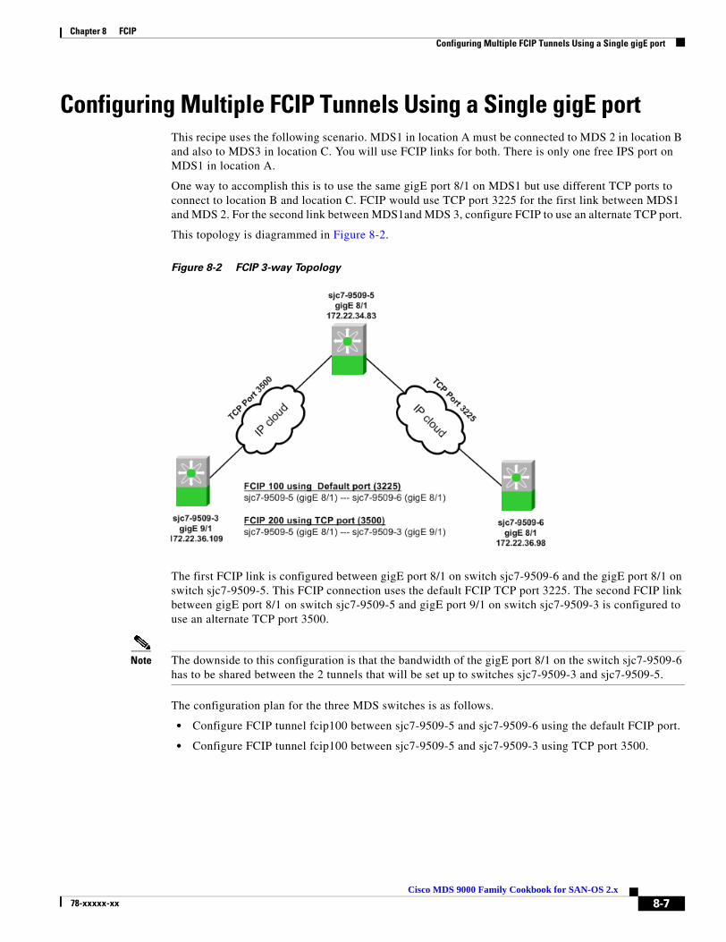
Chapter 8 FCIP Configuring Multiple FCIP Tunnels Using a Single gigE port
Configuring Multiple FCIP Tunnels Using a Single gigE port This recipe uses the following scenario. MDS1 in location A must be connected to MDS 2 in location B and also to MDS3 in location C. You will use FCIP links for both. There is only one free IPS port on MDS1 in location A.
One way to accomplish this is to use the same gigE port 8/1 on MDS1 but use different TCP ports to connect to location B and location C. FCIP would use TCP port 3225 for the first link between MDS1 and MDS 2. For the second link between MDS1and MDS 3, configure FCIP to use an alternate TCP port.
This topology is diagrammed in Figure 8-2.
Figure 8-2 FCIP 3-way Topology
The first FCIP link is configured between gigE port 8/1 on switch sjc7-9509-6 and the gigE port 8/1 on switch sjc7-9509-5. This FCIP connection uses the default FCIP TCP port 3225. The second FCIP link between gigE port 8/1 on switch sjc7-9509-5 and gigE port 9/1 on switch sjc7-9509-3 is configured to use an alternate TCP port 3500.
Note The downside to this configuration is that the bandwidth of the gigE port 8/1 on the switch sjc7-9509-6 has to be shared between the 2 tunnels that will be set up to switches sjc7-9509-3 and sjc7-9509-5.
The configuration plan for the three MDS switches is as follows.
• Configure FCIP tunnel fcip100 between sjc7-9509-5 and sjc7-9509-6 using the default FCIP port.
• Configure FCIP tunnel fcip100 between sjc7-9509-5 and sjc7-9509-3 using TCP port 3500.
8-7Cisco MDS 9000 Family Cookbook for SAN-OS 2.x
78-xxxxx-xx
Chapter 8 FCIP Configuring Multiple FCIP Tunnels Using a Single gigE port
To configure the tunnel fcip100, follow these steps:
Step 1 Configure the gigE interface on the MDS switches sjc7-9509-6 and sjc7-9509-5.
Give the gigE interface on the MDS switch sjc7-9509-5 an IP address and a subnetmask. This allows the gigE interface to communicate with the network.
sjc7-9509-5# conf tEnter configuration commands, one per line. End with CNTL/Z.sjc7-9509-5(config)# interface gigabitethernet 8/1sjc7-9509-5(config-if)# ip address 172.22.34.83 255.255.254.0 sjc7-9509-5(config-if)# no shutsjc7-9509-5(config-if)# ^Zsjc7-9509-5#
Give the gigE interface on the MDS switch sjc7-9509-5 an IP address and a subnetmask. This allows the gigE interface to communicate with the network.
sjc7-9509-6# conf tEnter configuration commands, one per line. End with CNTL/Z.sjc7-9509-6(config)# interface gigabitethernet 8/1sjc7-9509-6(config-if)# ip address 172.22.36.98 255.255.254.0 sjc7-9509-6(config-if)# no shutsjc7-9509-6(config-if)# ^Zsjc7-9509-5#
Step 2 Configure the IP route so the two gigE interfaces can communicate.
The IP route needs to be configured to allow the two gigE ports on switches sjc7-9509-5 and sjc7-9509-6 to communicate, but the gigE ports are in two different subnets. This means you need explicit routes for the switches to communicate.
Note We recommend that you create a host route to each of the two gigE interfaces with a subnet mask of 255.255.255.255. This allows only the two gigE interfaces to communicate.
For the gigE port 8/1 on the switch sjc7-9509-5 to communicate with the port gigE 8/1 on switch sjc7-9509-6 use this route configuration on switch sjc7-9509-5.
sjc7-9509-5# conf tEnter configuration commands, one per line. End with CNTL/Z.sjc7-9509-5(config)# ip route 172.22.36.98 255.255.255.255 172.22.34.1 interface gigabitethernet 8/1sjc7-9509-5(config)# ^Zsjc7-9509-5#
The configuration above provides this information: In order to reach 172.22.36.98 use the gateway 172.22.34.1 and interface gigE 8/1 on switch sjc7-9509-5.
For the gigE port 8/1 on switch sjc7-9509-6 to communicate with gigE port 8/1 on switch sjc7-9509-5, use this similar route configuration on switch sjc7-9509-6.
sjc7-9509-6# conf tEnter configuration commands, one per line. End with CNTL/Z.sjc7-9509-6(config)# ip route 172.22.34.83 255.255.255.255 172.22.36.1 interface gigabitethernet 8/1sjc7-9509-6(config-if)# ^Zsjc7-9509-6#
The configuration above provides this information: In order to reach 172.22.34.83 use the gateway 172.22.36.1 and interface gigE 8/1 on switch sjc7-9509-6.
8-8Cisco MDS 9000 Family Cookbook for SAN-OS 2.x
78-xxxxx-xx
Chapter 8 FCIP Configuring Multiple FCIP Tunnels Using a Single gigE port
Step 3 Ping the gigE interfaces to ensure that the gigE ports can communicate.
From the switch sjc7-9509-5, ping the IP address of the gigE interface 8/1 on switch sjc7-9509-6. Similarly, ping the IP address of the gigE interface 8/1 on switch sjc7-9509-5 from switch sjc7-9509-6. This can be done from the switch prompt.
sjc7-9509-5# ping 172.22.36.98PING 172.22.36.98 (172.22.36.98) 56(84) bytes of data.64 bytes from 172.22.36.98: icmp_seq=1 ttl=254 time=0.504 ms64 bytes from 172.22.36.98: icmp_seq=2 ttl=254 time=0.404 ms64 bytes from 172.22.36.98: icmp_seq=3 ttl=254 time=0.414 ms64 bytes from 172.22.36.98: icmp_seq=4 ttl=254 time=0.416 ms64 bytes from 172.22.36.98: icmp_seq=5 ttl=254 time=0.449 ms64 bytes from 172.22.36.98: icmp_seq=6 ttl=254 time=0.399 ms64 bytes from 172.22.36.98: icmp_seq=7 ttl=254 time=0.411 ms
--- 172.22.36.98 ping statistics ---7 packets transmitted, 7 received, 0% packet loss, time 5999msrtt min/avg/max/mdev = 0.399/0.428/0.504/0.036 mssjc7-9509-5#
sjc7-9509-6# ping 172.22.34.83PING 172.22.34.83 (172.22.34.83) 56(84) bytes of data.64 bytes from 172.22.34.83: icmp_seq=1 ttl=254 time=0.492 ms64 bytes from 172.22.34.83: icmp_seq=2 ttl=254 time=0.401 ms64 bytes from 172.22.34.83: icmp_seq=3 ttl=254 time=0.438 ms64 bytes from 172.22.34.83: icmp_seq=4 ttl=254 time=0.440 ms64 bytes from 172.22.34.83: icmp_seq=5 ttl=254 time=0.408 ms64 bytes from 172.22.34.83: icmp_seq=6 ttl=254 time=0.400 ms64 bytes from 172.22.34.83: icmp_seq=7 ttl=254 time=0.389 ms
--- 172.22.34.83 ping statistics ---7 packets transmitted, 7 received, 0% packet loss, time 5995msrtt min/avg/max/mdev = 0.386/0.412/0.492/0.037 mssjc7-9509-6#
Step 4 Measure the round trip time between the two gigE interfaces.
It is important to measure the round trip time between the interfaces. This value is required in the next step of the configuration.
sjc7-9509-5# ips measure-rtt 172.22.36.98 interface gigabitethernet 8/1Round trip time is 407 micro seconds (0.41 milli seconds)sjc7-9509-5#
sjc7-9509-6# ips measure-rtt 172.22.34.83 interface gigabitethernet 8/1Round trip time is 407 micro seconds (0.41 milli seconds)sjc7-9509-6#
Note FCIP uses port 3225. If there is a firewall between the two switches connected through FCIP then port 3225 needs to be opened for the FCIP tunnel to come up between the two switches. The VSAN (default VSAN 1) to which the FCIP interfaces belong to cannot be suspended. This will prevent the FCIP tunnel from coming up if TCP port 3225 is not opened.
8-9Cisco MDS 9000 Family Cookbook for SAN-OS 2.x
78-xxxxx-xx

Chapter 8 FCIP Configuring Multiple FCIP Tunnels Using a Single gigE port
Step 5 Configure the FCIP profile on both switches.
FCIP profiles need to be created as the profile defines the characteristics for the FCIP tunnel. The round trip time measured in the previous step is needed for profile configuration. In this case the round trip time is 407 micro seconds. The IP address used in the profile config below is the IP address assigned to the gigE interface on the switch associated with the profile.
Note We recommend that you use the same FCIP profile and FCIP interface numbers on both sides of the FCIP tunnel.
sjc7-9509-5# conf tEnter configuration commands, one per line. End with CNTL/Z.sjc7-9509-5(config)# fcip profile 100sjc7-9509-5(config-profile)# ip address 172.22.34.83sjc7-9509-5(config-profile)# tcp max-bandwidth-mbps 1000 min-available-bandwidth-mbps 500 round-trip-time-us 407sjc7-9509-5(config-profile)# ^Z sjc7-9509-5#
sjc7-9509-6# conf tEnter configuration commands, one per line. End with CNTL/Z.sjc7-9509-6(config)# fcip profile 100sjc7-9509-6(config-profile)# ip address 172.22.36.98ssjc7-9509-6(config-profile)# tcp max-bandwidth-mbps 1000 min-available-bandwidth-mbps 500 round-trip-time-us 407sjc7-9509-6(config-profile)# ^Zsjc7-9509-6#
The FCIP profile 100 is now defined on both the switches sjc7-9509-5 and sjc7-9509-6.
Step 6 Configure the FCIP interface on both the switches.
The FCIP interfaces need to be configured on both the switches. The configuration is as shown below.In the FCIP interface configuration the profile to used and the peer information (remote gigE’s IP address are specified.)are specified. Additionally compression and write acceleration can also be configured.
sjc7-9509-5# conf tEnter configuration commands, one per line. End with CNTL/Z.sjc7-9509-5(config)# interface fcip 100sjc7-9509-5(config-if)# peer-info ipaddr 172.22.36.98sjc7-9509-5(config-if)# use-profile 100sjc7-9509-5(config-if)# no shutdownsjc7-9509-5(config-if)#^Zsjc7-9509-5#
sjc7-9509-6# conf tEnter configuration commands, one per line. End with CNTL/Z.sjc7-9509-6(config)# int fcip 100sjc7-9509-6(config-if)# use-profile 100sjc7-9509-6(config-if)# peer-info ipaddr 172.22.34.84sjc7-9509-6(config-if)# no shutsjc7-9509-6(config-if)# endsjc7-9509-6#
8-10Cisco MDS 9000 Family Cookbook for SAN-OS 2.x
78-xxxxx-xx

Chapter 8 FCIP Configuring Multiple FCIP Tunnels Using a Single gigE port
Step 7 Make sure the first FCIP tunnel is up and running between switches sjc7-9509-6 and sjc7-9509-5.
Use a show interface FCIP 100 brief to show the status of the FCIP link between the two switches.
sjc7-9509-5# sh int fcip 100 br
-------------------------------------------------------------------------------Interface Vsan Admin Admin Status Oper Profile Eth Int Port-channel Mode Trunk Mode Mode-------------------------------------------------------------------------------fcip100 1 auto on trunking TE 100 GigabitEthernet8/1 --sjc7-9509-5#
sjc7-9509-6# sh int fcip 100 br
-------------------------------------------------------------------------------Interface Vsan Admin Admin Status Oper Profile Eth Int Port-channel Mode Trunk Mode Mode-------------------------------------------------------------------------------fcip100 1 auto on trunking TE 100 GigabitEthernet8/1 --sjc7-9509-6#
8-11Cisco MDS 9000 Family Cookbook for SAN-OS 2.x
78-xxxxx-xx

Chapter 8 FCIP Configuring Multiple FCIP Tunnels Using a Single gigE port
To configure the tunnel fcip200, follow these steps:
Step 1 Configure the gigE interface on the MDS switches sjc7-9509-3 Give the gigE interface on the MDS switch sjc7-9509-3 an IP address and a subnetmask. This allows the gigE interface to communicate with the network.
sjc7-9509-3# conf tEnter configuration commands, one per line. End with CNTL/Z.sjc7-9509-3(config)# interface gigabitethernet 9/1sjc7-9509-3(config-if)# ip address 172.22.36.109 255.255.254.0sjc7-9509-3(config-if)# no shutsjc7-9509-3(config-if)# endsjc7-9509-3#
Step 2 Configure an IP route so the two gigE ports can communicate.
Since the two gigE ports are in different subnets, an explicit route is needed for them to communicate. Configure an IP route between the gigE ports on switches sjc7-9509-3 and sjc7-9509-6.
Tip We recommend that you create a host route to each of the two gigE interfaces with a subnet mask of 255.255.255.255. This allows only the two gigE interfaces to communicate.
Syntax for configuring a route is shown below. For the gigE port 8/1 on the switch sjc7-9509-5 to communicate with the port gigE 9/1 on switch sjc7-9509-3, the following route configuration must be done on switch sjc7-9509-5.
sjc7-9509-5# conf tEnter configuration commands, one per line. End with CNTL/Z.sjc7-9509-5(config)# ip route 172.22.36.109 255.255.255.255 172.22.34.1 interface gigabitethernet 8/1sjc7-9509-5(config)# ^Zsjc7-9509-5#
The above configuration provides this information: In order to reach 172.22.36.109 use the gateway 172.22.36.1 and interface gigE 8/1 on switch sjc7-9509-5.
Similarly, for the gigE port 9/1 on switch sjc7-9509-3 to communicate with gigE port 8/1 on switch sjc7-9509-5, the following route configuration must be done on switch sjc7-9509-3.
sjc7-9509-3# conf tEnter configuration commands, one per line. End with CNTL/Z.sjc7-9509-3(config)# ip route 172.22.34.83 255.255.255.255 172.22.36.1 interface gigabitethernet 9/1sjc7-9509-3(config)# endsjc7-9509-3#
The above configuration provides this information: In order to reach 172.22.34.83 use the gateway 172.22.36.1 and interface gigE 9/1 on switch sjc7-9509-3.
Step 3 Ping the gigE interfaces to ensure that the gigE ports can communicate.
From the switch sjc7-9509-5 ping the IP address of the gigE interface 9/1 on switch sjc7-9509-3. Similarly, ping the IP address of the gigE interface 8/1 on switch sjc7-9509-5 from switch sjc7-9509-3. This can be done from the switch prompt.
sjc7-9509-5# ping 172.22.36.109PING 172.22.36.109 (172.22.36.109) 56(84) bytes of data.64 bytes from 172.22.36.109: icmp_seq=1 ttl=254 time=0.351 ms64 bytes from 172.22.36.109: icmp_seq=2 ttl=254 time=0.399 ms
8-12Cisco MDS 9000 Family Cookbook for SAN-OS 2.x
78-xxxxx-xx

Chapter 8 FCIP Configuring Multiple FCIP Tunnels Using a Single gigE port
64 bytes from 172.22.36.109: icmp_seq=3 ttl=254 time=0.405 ms64 bytes from 172.22.36.109: icmp_seq=4 ttl=254 time=0.408 ms64 bytes from 172.22.36.109: icmp_seq=5 ttl=254 time=0.398 ms64 bytes from 172.22.36.109: icmp_seq=6 ttl=254 time=0.410 ms
--- 172.22.36.109 ping statistics ---6 packets transmitted, 6 received, 0% packet loss, time 4998msrtt min/avg/max/mdev = 0.398/5.525/26.018/10.246 mssjc7-9509-5#
sjc7-9509-3# ping 172.22.34.83PING 172.22.34.83 (172.22.34.83) 56(84) bytes of data.64 bytes from 172.22.34.83: icmp_seq=1 ttl=254 time=0.542 ms64 bytes from 172.22.34.83: icmp_seq=2 ttl=254 time=0.408 ms64 bytes from 172.22.34.83: icmp_seq=3 ttl=254 time=0.424 ms64 bytes from 172.22.34.83: icmp_seq=4 ttl=254 time=0.430 ms64 bytes from 172.22.34.83: icmp_seq=5 ttl=254 time=0.404 ms64 bytes from 172.22.34.83: icmp_seq=6 ttl=254 time=0.448 ms
--- 172.22.34.83 ping statistics ---6 packets transmitted, 6 received, 0% packet loss, time 4995msrtt min/avg/max/mdev = 0.404/0.442/0.542/0.052 mssjc7-9509-3#
Step 4 Measure the round trip time between the two gigE interfaces.
It is important to measure the round trip time between the interfaces. This value is required in the next configuration step.
sjc7-9509-5# ips measure-rtt 172.22.36.109 interface gigabitethernet 8/1Round trip time is 408 micro seconds (0.41 milli seconds)sjc7-9509-5#
sjc7-9509-3# ips measure-rtt 172.22.34.83 interface gigabitethernet 9/1Round trip time is 407 micro seconds (0.41 milli seconds)sjc7-9509-3#
Note FCIP uses port 3225 by default. Since the FCIP tunnel to sjc7-9509-6 is already up and using TCP port 3225, this tunnel will use port 3500.
Step 5 Configure the FCIP profile on both the switches.
An FCIP profile needs to be created because a profile defines the characteristics for the FCIP tunnel. The round trip time measured is needed for profile configuration. In this case the round trip time is 407 micro seconds. The IP address used in the profile config below is the IP address assigned to the gigE interface on the switch associated with the profile.
Tip We recommend that you use the same FCIP profile and FCIP interface numbers on both switches for an FCIP tunnel.
sjc7-9509-5# conf tEnter configuration commands, one per line. End with CNTL/Z.sjc7-9509-5(config)# fcip profile 200sjc7-9509-5(config-profile)# port 3500sjc7-9509-5(config-profile)# ip address 172.22.34.83sjc7-9509-5(config-profile)# tcp max-bandwidth-mbps 1000 min-available-bandwidth-mbps 500 round-trip-time-us 407sjc7-9509-5(config-profile)# endsjc7-9509-5#
8-13Cisco MDS 9000 Family Cookbook for SAN-OS 2.x
78-xxxxx-xx
Chapter 8 FCIP Configuring Multiple FCIP Tunnels Using a Single gigE port
sjc7-9509-3# conf tEnter configuration commands, one per line. End with CNTL/Z.sjc7-9509-3(config)# fcip profile 200sjc7-9509-3(config-profile)# port 3500sjc7-9509-3(config-profile)# ip address 172.22.36.109sjc7-9509-3(config-profile)# tcp max-bandwidth-mbps 1000 min-available-bandwidth-mbps 500 round-trip-time-us 407sjc7-9509-3(config-profile)# endsjc7-9509-3#
At this stage of the configuration the FCIP profile 200 has been defined on both the switches sjc7-9509-5 and sjc7-9509-3 on TCP port 3500.
Step 6 Configure the FCIP interface on both switches.
In the FCIP interface configuration, the profile and peer information (remote gigE’s IP address) are specified. Additionally compression and write acceleration can also be configured.
sjc7-9509-5# conf tEnter configuration commands, one per line. End with CNTL/Z.sjc7-9509-5(config)# interface fcip 200sjc7-9509-5(config-if)# peer-info ipaddr 172.22.36.109 port 3500sjc7-9509-5(config-if)# use-profile 200sjc7-9509-5(config-if)# no shutsjc7-9509-5(config-if)# endsjc7-9509-5#
sjc7-9509-3# conf tEnter configuration commands, one per line. End with CNTL/Z.sjc7-9509-3(config)# interface fcip 200sjc7-9509-3(config-if)# peer-info ipaddr 172.22.34.83 port 3500sjc7-9509-3(config-if)# use-profile 200sjc7-9509-3(config-if)# no shutsjc7-9509-3(config-if)# endsjc7-9509-3#
Step 7 Check to see that the first FCIP tunnel is up and running between switches sjc7-9509-6 and sjc7-9509-5.
The command show interface fcip 100 brief shows the status of the FCIP link between the two switches.
sjc7-9509-5# show interface fcip 100-200 brief
-------------------------------------------------------------------------------Interface Vsan Admin Admin Status Oper Profile Eth Int Port-channel Mode Trunk Mode Mode-------------------------------------------------------------------------------fcip100 1 auto on trunking TE 100 GigabitEthernet8/1 --fcip200 1 auto on trunking TE 200 GigabitEthernet8/1 --sjc7-9509-5
sjc7-9509-3# show interface fcip 200 brief
-------------------------------------------------------------------------------Interface Vsan Admin Admin Status Oper Profile Eth Int Port-channel Mode Trunk Mode Mode-------------------------------------------------------------------------------fcip200 1 auto on trunking TE 200 GigabitEthernet9/1 --sjc7-9509-3#
8-14Cisco MDS 9000 Family Cookbook for SAN-OS 2.x
78-xxxxx-xx

Chapter 8 FCIP Configuring FCIP with IPsec using FM
Configuring FCIP with IPsec using FMFabric Manager (FM) can be used to configure FCIP. The following recipe demonstrates how IPsec can be configured for an FCIP link. IPSec is supported only on the 14+2 blade in the MDS 9000 series of switches. MDS 9216i has the 14+2 built into the supervisor and hence supports IPSec.
The topology used in this recipe is shown in Figure 8-3.
Figure 8-3 FCIP and IPSec Topology
To enable FCIP on the switches sjc7-9216-3 and sjc7-9216-6 and apply the configuration, follow these steps:
Step 1 Select FCIP in the Physical Attributes Pane. This selection is circled with a blue box in Figure 8-4. Once this is selected, the right pane is populated with a list of fabric switches seen by FM, including the state of FCIP in each switch.
Step 2 Press the CTRL+TAB keys to select the switch sjc7-9216-3.
Step 3 Expand the drop-down box in the command column and choose FCIP. This process is marked by a red box in Figure 8-4.
Step 4 Repeat steps 1 through 3 for the switch sjc7-9216-6.
Figure 8-4 Enable FCIP through Fabric Manager
8-15Cisco MDS 9000 Family Cookbook for SAN-OS 2.x
78-xxxxx-xx

Chapter 8 FCIP Configuring FCIP with IPsec using FM
Step 5 Click the green Apply Changes icon (see Figure 8-5) to apply the changes to the switch.
Figure 8-5 FM Apply Changes to switches.
You see the results shown in Figure 8-6.
Figure 8-6 Enable Results
Note IPSec is available only when the 14 + 2 module is used in MDS 9216, MDS 9506, MDS 9509 or an MDS 9216i is used.
8-16Cisco MDS 9000 Family Cookbook for SAN-OS 2.x
78-xxxxx-xx
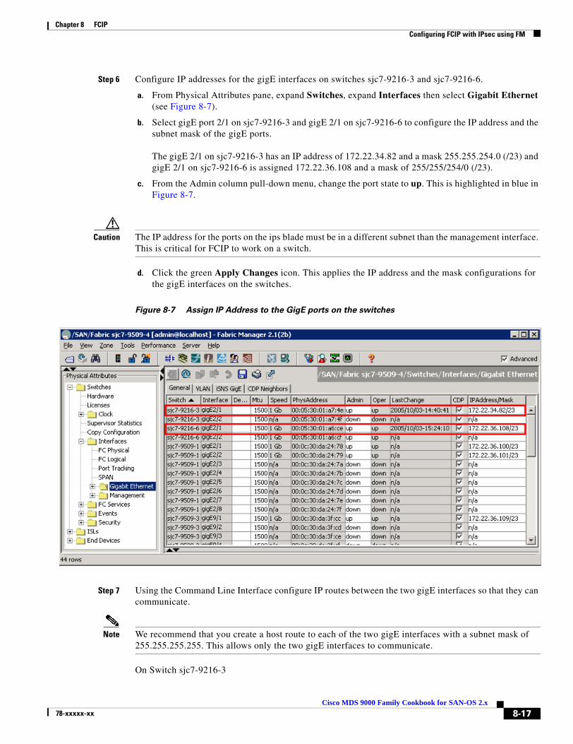
Chapter 8 FCIP Configuring FCIP with IPsec using FM
Step 6 Configure IP addresses for the gigE interfaces on switches sjc7-9216-3 and sjc7-9216-6.
a. From Physical Attributes pane, expand Switches, expand Interfaces then select Gigabit Ethernet (see Figure 8-7).
b. Select gigE port 2/1 on sjc7-9216-3 and gigE 2/1 on sjc7-9216-6 to configure the IP address and the subnet mask of the gigE ports.
The gigE 2/1 on sjc7-9216-3 has an IP address of 172.22.34.82 and a mask 255.255.254.0 (/23) and gigE 2/1 on sjc7-9216-6 is assigned 172.22.36.108 and a mask of 255/255/254/0 (/23).
c. From the Admin column pull-down menu, change the port state to up. This is highlighted in blue in Figure 8-7.
Caution The IP address for the ports on the ips blade must be in a different subnet than the management interface. This is critical for FCIP to work on a switch.
d. Click the green Apply Changes icon. This applies the IP address and the mask configurations for the gigE interfaces on the switches.
Figure 8-7 Assign IP Address to the GigE ports on the switches
Step 7 Using the Command Line Interface configure IP routes between the two gigE interfaces so that they can communicate.
Note We recommend that you create a host route to each of the two gigE interfaces with a subnet mask of 255.255.255.255. This allows only the two gigE interfaces to communicate.
On Switch sjc7-9216-3
8-17Cisco MDS 9000 Family Cookbook for SAN-OS 2.x
78-xxxxx-xx
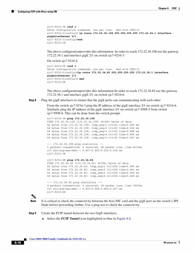
Chapter 8 FCIP Configuring FCIP with IPsec using FM
sjc7-9216-3# conf tEnter configuration commands, one per line. End with CNTL/Z.sjc7-9216-3(config)# ip route 172.22.36.108 255.255.255.255 172.22.34.1 interface gigabitethernet 2/1sjc7-9216-3(config)#endsjc7-9216-3#
The above configurationprovides this information: In order to reach 172.22.36.108 use the gateway 172.22.34.1 and interface gigE 2/1 on switch sjc7-9216-3.
On switch sjc7-9216-6
sjc7-9216-6# conf tEnter configuration commands, one per line. End with CNTL/Z.sjc7-9216-6(config)#ip route 172.22.34.82 255.255.255.255 172.22.36.1 interface gigabitethernet 2/1sjc7-9216-6(config)# endsjc7-9216-6#
The above configurationprovides this information:In order to reach 172.22.34.82 use the gateway 172.22.36.1 and interface gigE 2/1 on switch sjc7-9216-6.
Step 8 Ping the gigE interfaces to ensure that the gigE ports can communicating with each other
From the switch sjc7-9216-3 ping the IP address of the gigE interface 2/1 on switch sjc7-9216-6. Similarly ping the IP address of the gigE interface 2/1 on switch sjc7-9509-5 from switch sjc7-9509-6. This can be done from the switch prompt.
sjc7-9216-3# ping 172.22.36.108PING 172.22.36.108 (172.22.36.108) 56(84) bytes of data.64 bytes from 172.22.36.108: icmp_seq=1 ttl=63 time=0.495 ms64 bytes from 172.22.36.108: icmp_seq=2 ttl=63 time=0.524 ms64 bytes from 172.22.36.108: icmp_seq=3 ttl=63 time=0.488 ms64 bytes from 172.22.36.108: icmp_seq=4 ttl=63 time=0.496 ms64 bytes from 172.22.36.108: icmp_seq=5 ttl=63 time=0.467 ms
--- 172.22.36.108 ping statistics ---5 packets transmitted, 5 received, 0% packet loss, time 4012msrtt min/avg/max/mdev = 0.467/0.493/0.524/0.034 mssjc7-9216-3#
sjc7-9216-6# ping 172.22.34.82PING 172.22.34.82 (172.22.34.82) 56(84) bytes of data.64 bytes from 172.22.34.82: icmp_seq=1 ttl=254 time=0.495 ms64 bytes from 172.22.34.82: icmp_seq=2 ttl=254 time=0.461 ms64 bytes from 172.22.34.82: icmp_seq=3 ttl=254 time=0.450 ms64 bytes from 172.22.34.82: icmp_seq=4 ttl=254 time=0.468 ms
--- 172.22.34.82 ping statistics ---4 packets transmitted, 4 received, 0% packet loss, time 2997msrtt min/avg/max/mdev = 0.450/0.468/0.495/0.027 mssjc7-9216-6#
Note It is critical to check the connectivity between the host NIC card and the gigE port on the switch’s IPS blade before proceeding further. Use a ping test to check the connectivity.
Step 9 Create the FCIP tunnel between the two GigE interfaces.
a. Select the FCIP Tunnel icon highlighted in blue in Figure 8-8.
8-18Cisco MDS 9000 Family Cookbook for SAN-OS 2.x
78-xxxxx-xx

Chapter 8 FCIP Configuring FCIP with IPsec using FM
Figure 8-8 FCIP Tunnel Icon in FM
The FCIP Tunnel Wizard launches as shown in Figure 8-9.
Figure 8-9 FCIP tunnel Wizard Start Screen
b. In the start screen shown in Figure 8-9, select two switches that are will be connected with FCIP. In this recipe, the switches are sjc7-9216-3 and sjc7-9216-6.
c. Click Next. You see the selected switches and their available gigE ports as shown in Figure 8-10.
8-19Cisco MDS 9000 Family Cookbook for SAN-OS 2.x
78-xxxxx-xx
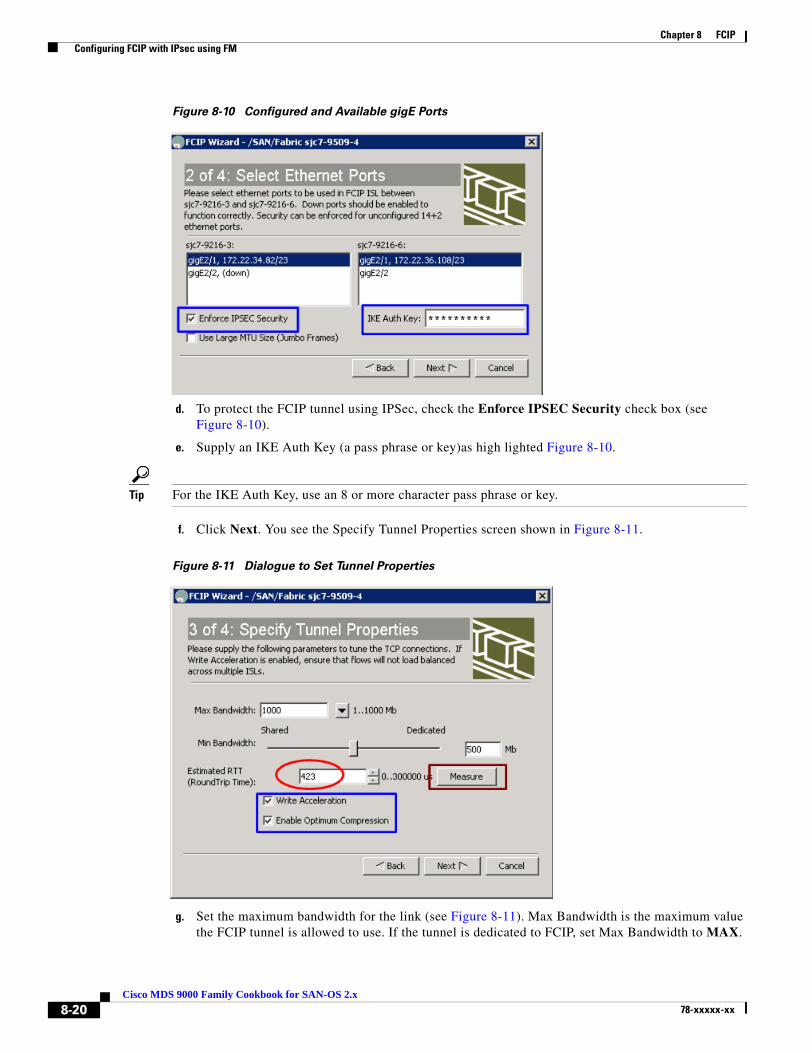
Chapter 8 FCIP Configuring FCIP with IPsec using FM
Figure 8-10 Configured and Available gigE Ports
d. To protect the FCIP tunnel using IPSec, check the Enforce IPSEC Security check box (see Figure 8-10).
e. Supply an IKE Auth Key (a pass phrase or key)as high lighted Figure 8-10.
Tip For the IKE Auth Key, use an 8 or more character pass phrase or key.
f. Click Next. You see the Specify Tunnel Properties screen shown in Figure 8-11.
Figure 8-11 Dialogue to Set Tunnel Properties
g. Set the maximum bandwidth for the link (see Figure 8-11). Max Bandwidth is the maximum value the FCIP tunnel is allowed to use. If the tunnel is dedicated to FCIP, set Max Bandwidth to MAX.
8-20Cisco MDS 9000 Family Cookbook for SAN-OS 2.x
78-xxxxx-xx

Chapter 8 FCIP Configuring FCIP with IPsec using FM
h. The minimum bandwidth value is based on whether the link is shared or dedicated to FCIP. Click Measure to estimate the round trip time (see Figure 8-11). You see a screen that measures the RTT between the two gigE interfaces (see Figure 8-12).
Figure 8-12 Measure RTT output screen.
Minimum bandwidth is based on this RTT. In this topology, the RTT was 423 micro seconds (see Figure 8-12).
i. Turn on write acceleration and compression by checking the corresponding checkboxes as shown in Figure 8-11.
j. Click Next. You see the Create FCIP ISL screen.
Figure 8-13 Create FCIP ISL
Step 10 Verify the switches and the interfaces being connected.
Step 11 Select trunk to turn on trunk mode (see red circle in Figure 8-13). This lets VSANs flow through the link.
In this screen the VSANS allowed through the FCIP link can be changes in the VSAN list dialogue.
Step 12 Click Finish. You see a screen prompting you to enable IPSEC on the two switches. (see Figure 8-14).
8-21Cisco MDS 9000 Family Cookbook for SAN-OS 2.x
78-xxxxx-xx

Chapter 8 FCIP Configuring FCIP with IPsec using FM
Step 13 Click Yes (see Figure 8-14).
Figure 8-14 Enable IPsec on the Two Switches.
Tunnel creation is complete. The FCIP link secured by IPSec is configured and up.
8-22Cisco MDS 9000 Family Cookbook for SAN-OS 2.x
78-xxxxx-xx
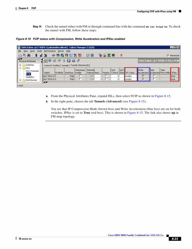
Chapter 8 FCIP Configuring FCIP with IPsec using FM
Step 14 Check the tunnel either with FM or through command line with the command sh int fcip2 br. To check the tunnel with FM, follow these steps:
Figure 8-15 FCIP status with Compression, Write Acceleration and IPSec enabled
a. From the Physical Attributes Pane, expand ISLs, then select FCIP as shown in Figure 8-15.
b. In the right pane, choose the tab Tunnels (Advanced) (see Figure 8-15).
You see that IP Compression Mode (brown box) and Write Acceleration (blue box) are on for both switches. IPSec is set to True (red box). This is shown in Figure 8-15. The link also shows up in FM map topology.
8-23Cisco MDS 9000 Family Cookbook for SAN-OS 2.x
78-xxxxx-xx
Chapter 8 FCIP Tuning FCIP
Tuning FCIPConfiguring and bringing up a FCIP tunnel establishes an ISL between two switches. To achieve greater efficiency and utilization from the link, optimize link parameters. This optimization is specific to each FCIP link between switches. Optimization for a FCIP link over a slow 1.54 Mb/s connection will be different than that done for an FCIP link over a 1Gb/s connection with very low latency. This section provides insight into optimization of FCIP links.
Note Individual results may vary due to network conditions (existing link utilization / quality) as well as the storage array and host type using the FCIP tunnel.
TCP Tuning: Latency and Available BandwidthThe latency of an FCIP link is the amount of time it takes a packet to go from one end of the link to the other. Latency is affected by many factors including distance and the number of devices that it must traverse. Even the fastest routers and switches incur some latency.
Even though latency cannot be eliminated, protocols can be tuned and MDS switch features (such as FCIP Write Acceleration) can be enabled to minimize its effect. These features are enabled in the FCIP profile.
Available bandwidth is the amount of bandwidth that the FCIP link can use on the network. You define a maximum and a minimum value for the FCIP link in the FCIP profile.
• The maximum available bandwidth value is the maximum amount of bandwidth that the FCIP link can use on the network.
• The minimum available bandwidth value is used as a guideline for the minimum value. If there are serious problems on the network (dropped packets, congestion), the link goes slower than the minimum value. We recommend that the minimum value be set (at least) to the minimum accepted by applications (EMC SRDF, IBM PPRC etc.).
Tip If the underlying link is dedicated to FCIP, the minimum and maximum available bandwidth values should be the same.
8-24Cisco MDS 9000 Family Cookbook for SAN-OS 2.x
78-xxxxx-xx

Chapter 8 FCIP Tuning FCIP
Table 8-1 contains some common WAN links and their speeds. These circuits are most often used as the underlying network for a FCIP link. For example, the underlying network may be a OC3 but you may only be able to use 100Mb of that link.
Tip When deploying FCIP, you should always involve the LAN and WAN teams to find out about the connections they are providing you. If there are performance issues, they can often help you troubleshoot them from the network standpoint. Involve them earlier rather than later.
Table 8-1 Common WAN circuit speeds
Enabling FCIP Write AccelerationIPS-8, IPS-4 and 14+2 blades support write acceleration to help alleviate the affects of latency.
Note Only in MDS SAN-OS version 2.0.1b and higher should write acceleration be used with Port-Channels.
This recipe enables Write Acceleration.
sjc7-9509-5# conf tEnter configuration commands, one per line. End with CNTL/Z.sjc7-9509-5(config)# interface fcip 100sjc7-9509-5(config)# write-acceleratorsjc7-9509-5(config)# endsjc7-9509-5#
sjc7-9509-6# conf tEnter configuration commands, one per line. End with CNTL/Z.sjc7-9509-6(config)# interface fcip 100sjc7-9509-6(config)# write-acceleratorsjc7-9509-6(config)# endsjc7-9509-6#
Circuit Name Link Speed
T1 1.544 Megabits/sec
T3 44.736 Megabits/sec
OC3 155 Megabits/sec
OC12 622 Megabits/sec
OC24 1.244 Gigabits/sec
OC48 2.488 Gigabits/sec
OC192 10 Gigabits/sec
OC 768 40 Gigabits/sec
8-25Cisco MDS 9000 Family Cookbook for SAN-OS 2.x
78-xxxxx-xx
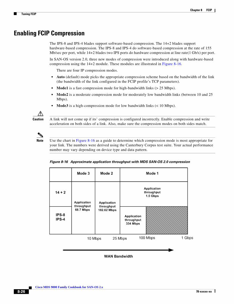
Chapter 8 FCIP Tuning FCIP
Enabling FCIP CompressionThe IPS-8 and IPS-4 blades support software-based compression. The 14+2 blades support hardware-based compression. The IPS-8 and IPS-4 do software-based compression at the rate of 155 Mb/sec per port, while 14+2 blades two IPS ports do hardware compression at line rate(1 Gb/s) per port.
In SAN-OS version 2.0, three new modes of compression were introduced along with hardware-based compression using the 14+2 module. These modules are illustrated in Figure 8-16.
There are four IP compression modes.
• Auto (default) mode picks the appropriate compression scheme based on the bandwidth of the link (the bandwidth of the link configured in the FCIP profile’s TCP parameters).
• Mode1 is a fast compression mode for high-bandwidth links (> 25 Mbps).
• Mode2 is a moderate compression mode for moderately low bandwidth links (between 10 and 25 Mbps).
• Mode3 is a high-compression mode for low bandwidth links (< 10 Mbps).
Caution A link will not come up if its’ compression is configured incorrectly. Enable compression and write acceleration on both sides of a link. Also, make sure the compression modes on both sides match.
Note Use the chart in Figure 8-16 as a guide to determine which compression mode is most appropriate for your link. The numbers were derived using the Canterbury Corpus test suite. Your actual performance number may vary depending on device type and data pattern.
Figure 8-16 Approximate application throughput with MDS SAN-OS 2.0 compression
8-26Cisco MDS 9000 Family Cookbook for SAN-OS 2.x
78-xxxxx-xx

Chapter 8 FCIP Tuning FCIP
This recipe enables IP compression for an FCIP tunnel.
sjc7-9509-5# conf tEnter configuration commands, one per line. End with CNTL/Z.sjc7-9509-5(config)# interface fcip 100sjc7-9509-5(config)# ip-compression mode1sjc7-9509-5(config)# ^Zsjc7-9509-5#
sjc7-9509-6# conf tEnter configuration commands, one per line. End with CNTL/Z.sjc7-9509-6(config)# interface fcip 100sjc7-9509-6(config)# ip-compression mode1sjc7-9509-6(config)# ^Zsjc7-9509-6#
Enabling Tape AccelerationThe tape acceleration feature is similar to write acceleration. Tape acceleration alleviates issues associated with backing up to tape drives through FCIP tunnels over long-distance WAN links.
Caution FCIP Tape acceleration does not work if an FCIP port is part of a port channel. It also won’t work if there are multiple paths with equal costs between the backup host and the tape device.
Tip We recommend that you have multiple paths between the backup server and the tape device, and configure the multiple paths with varying costs (i.e. FSPF cost of the FCIP link). This ensures that only one link at a time is used for tape acceleration and provides failover if the current link fails.
Enabling Tape Acceleration from the CLI
This recipe enables tape acceleration from the CLI.
sjc7-9216-3# conf tEnter configuration commands, one per line. End with CNTL/Z.sjc7-9216-3(config)# int fcip2sjc7-9216-3(config-if)# write-accelerator tape-acceleratorsjc7-9216-3(config-if)#shut sjc7-9216-3(config-if)#no shut sjc7-9216-3#
sjc7-9216-6# conf tEnter configuration commands, one per line. End with CNTL/Z.sjc7-9216-6(config)# int fcip2sjc7-9216-6(config-if)# write-accelerator tape-acceleratorsjc7-9216-6(config-if)#shut sjc7-9216-6(config-if)#no shut sjc7-9216-6#
8-27Cisco MDS 9000 Family Cookbook for SAN-OS 2.x
78-xxxxx-xx
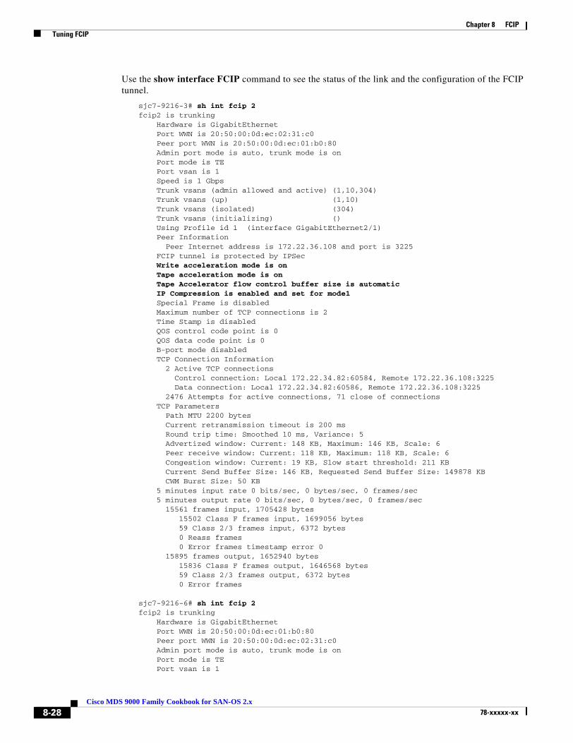
Chapter 8 FCIP Tuning FCIP
Use the show interface FCIP command to see the status of the link and the configuration of the FCIP tunnel.
sjc7-9216-3# sh int fcip 2fcip2 is trunking Hardware is GigabitEthernet Port WWN is 20:50:00:0d:ec:02:31:c0 Peer port WWN is 20:50:00:0d:ec:01:b0:80 Admin port mode is auto, trunk mode is on Port mode is TE Port vsan is 1 Speed is 1 Gbps Trunk vsans (admin allowed and active) (1,10,304) Trunk vsans (up) (1,10) Trunk vsans (isolated) (304) Trunk vsans (initializing) () Using Profile id 1 (interface GigabitEthernet2/1) Peer Information Peer Internet address is 172.22.36.108 and port is 3225 FCIP tunnel is protected by IPSec Write acceleration mode is on Tape acceleration mode is on Tape Accelerator flow control buffer size is automatic IP Compression is enabled and set for mode1 Special Frame is disabled Maximum number of TCP connections is 2 Time Stamp is disabled QOS control code point is 0 QOS data code point is 0 B-port mode disabled TCP Connection Information 2 Active TCP connections Control connection: Local 172.22.34.82:60584, Remote 172.22.36.108:3225 Data connection: Local 172.22.34.82:60586, Remote 172.22.36.108:3225 2476 Attempts for active connections, 71 close of connections TCP Parameters Path MTU 2200 bytes Current retransmission timeout is 200 ms Round trip time: Smoothed 10 ms, Variance: 5 Advertized window: Current: 148 KB, Maximum: 146 KB, Scale: 6 Peer receive window: Current: 118 KB, Maximum: 118 KB, Scale: 6 Congestion window: Current: 19 KB, Slow start threshold: 211 KB Current Send Buffer Size: 146 KB, Requested Send Buffer Size: 149878 KB CWM Burst Size: 50 KB 5 minutes input rate 0 bits/sec, 0 bytes/sec, 0 frames/sec 5 minutes output rate 0 bits/sec, 0 bytes/sec, 0 frames/sec 15561 frames input, 1705428 bytes 15502 Class F frames input, 1699056 bytes 59 Class 2/3 frames input, 6372 bytes 0 Reass frames 0 Error frames timestamp error 0 15895 frames output, 1652940 bytes 15836 Class F frames output, 1646568 bytes 59 Class 2/3 frames output, 6372 bytes 0 Error frames
sjc7-9216-6# sh int fcip 2fcip2 is trunking Hardware is GigabitEthernet Port WWN is 20:50:00:0d:ec:01:b0:80 Peer port WWN is 20:50:00:0d:ec:02:31:c0 Admin port mode is auto, trunk mode is on Port mode is TE Port vsan is 1
8-28Cisco MDS 9000 Family Cookbook for SAN-OS 2.x
78-xxxxx-xx

Chapter 8 FCIP Tuning FCIP
Speed is 1 Gbps Trunk vsans (admin allowed and active) (1,5,10,39,200,301) Trunk vsans (up) (1,10) Trunk vsans (isolated) (5,39,200,301) Trunk vsans (initializing) () Using Profile id 1 (interface GigabitEthernet2/1) Peer Information Peer Internet address is 172.22.34.82 and port is 3225 FCIP tunnel is protected by IPSec Write acceleration mode is on Tape acceleration mode is on Tape Accelerator flow control buffer size is automatic IP Compression is enabled and set for mode1 Special Frame is disabled Maximum number of TCP connections is 2 Time Stamp is disabled QOS control code point is 0 QOS data code point is 0 B-port mode disabled TCP Connection Information 2 Active TCP connections Control connection: Local 172.22.36.108:3225, Remote 172.22.34.82:60584 Data connection: Local 172.22.36.108:3225, Remote 172.22.34.82:60586 2458 Attempts for active connections, 72 close of connections TCP Parameters Path MTU 2200 bytes Current retransmission timeout is 200 ms Round trip time: Smoothed 8 ms, Variance: 6 Advertized window: Current: 118 KB, Maximum: 26 KB, Scale: 6 Peer receive window: Current: 148 KB, Maximum: 148 KB, Scale: 6 Congestion window: Current: 14 KB, Slow start threshold: 211 KB Current Send Buffer Size: 26 KB, Requested Send Buffer Size: 26948 KB CWM Burst Size: 50 KB 5 minutes input rate 0 bits/sec, 0 bytes/sec, 0 frames/sec 5 minutes output rate 0 bits/sec, 0 bytes/sec, 0 frames/sec 15336 frames input, 1606556 bytes 15277 Class F frames input, 1600184 bytes 59 Class 2/3 frames input, 6372 bytes 0 Reass frames 0 Error frames timestamp error 0 15565 frames output, 1705796 bytes 15506 Class F frames output, 1699424 bytes 59 Class 2/3 frames output, 6372 bytes 0 Error framessjc7-9216-6#
In this output from sjc7-9126-3 and sjc7-9216-6 the link properties are in bold.
8-29Cisco MDS 9000 Family Cookbook for SAN-OS 2.x
78-xxxxx-xx

Chapter 8 FCIP Tuning FCIP
Enabling Tape Acceleration from the CLI
This recipe enables tape acceleration from Fabric Manager.
Step 1 From the Physical Attributes pane, expand ISLs and select FCIP (see Figure 8-17).
Step 2 In the right pane, choose the Tunnels (Advanced) tab.
Step 3 Check the Tape Acceleration checkboxes on both switches (see the blue box in Figure 8-17).
Step 4 Click the green Apply Config icon to apply the config to the switches (see the red box in Figure 8-17).
Figure 8-17 Activating Tape Acceleration in FM
Tune the Tape FlowCtrl buffer size (0 == auto) (see the brown box in Figure 8-17).
8-30Cisco MDS 9000 Family Cookbook for SAN-OS 2.x
78-xxxxx-xx
Chapter 8 FCIP Testing and Tuning the FCIP link with SET
Testing and Tuning the FCIP link with SETUse SAN Extension Tuner (SET) to test and tune performance for the FCIP link. SET generates SCSI I/O commands and directs them to virtual targets. SET allows for variation of the I/O type (read/writes) transfer size and the number of concurrent I/Os generated.
SET lets you determine I/Os and throughput (MB) per second, as well as I/O latency. This helps in the fine tuning of FCIP throughput. Having these metrics validates characteristics of the WAN circuit. as well as determining the potential throughput of the FCIP tunnel without involving a host or disk subsystem.
Use SET to create consistent traffic flows, and enable such features as Write Acceleration, Tape Acceleration, compression and encryption to determine their effect on the throughput of the tunnel. Also use SET to tune modifications to the FCIP tunnel’s round trip time, and view maximum and minimum bandwidth.
Additionally, SET can be used to model an array to see if the array is performing up to spec (number of outstanding I/Os, size of transfers).
Tip SET requires the SAN_EXTN_OVER_IP license to work.
SET also requires the following.
• Two IPS modules.
• FCIP link between the switches.
• One unused gigabit ethernet port per switch to act as a initiator or target.
• Physical layer of the second gigabit ethernet port should be up.
• Enabling ISCSI on both the switches.
• Enabling SAN-EXT-TUNER.
SET works by creating virtual initiators and targets behind two gigabit ethernet ports. These virtual devices are created in a VSAN, they have pWWNs and they obtain FCIDs just like real end devices do. They are required to be zoned together to communicate, and they send standard FCP commands to each other which are handled by the fibre channel infrastructure as is normal FC traffic. The frames are routed via FSPF to their destinations and can travel on E and TE ports through MDS and non-MDS switches. If the minimum requirements are met, SET can be used to test optical networks not just FCIP links.
While the same gigabit ethernet port that is configured for FCIP can be used as a target or initiator, we do not recommend it. as this may interfere with the ability to generate sufficient bandwidth. Always use an unused gigabit ethernet port for the initiator and target.
Note This SET recipe assumes that the FCIP link is already up and functional. For directions, see Configuring FCIP on a Switch with CLI, page 8-2
8-31Cisco MDS 9000 Family Cookbook for SAN-OS 2.x
78-xxxxx-xx

Chapter 8 FCIP Testing and Tuning the FCIP link with SET
For this recipe the following resources are used:
• Switch: sjc7-9216-5:
Additional gigE port: gig2/2
VSAN 1000
Virtual nwwn: 10:00:00:00:00:00:00:00
Virtual pwwn: 20:00:00:00:00:00:00:01
• Switch: sjc7-9216-6
Additional gigE port: gig2/2:
VSAN 1000
Virtual nwwn 11:00:00:00:00:00:00:00
Virtual pwwn: 30:00:00:00:00:00:00:01
To tune a link, follow these steps:
Step 1 Enable the second gigabit ethernet port on both the switches. In this recipe gigE port 2/2 is used on both switches for SET.
Tip This additional gigE port does not require an IP address to be assigned. Only the physical layer is required to be up.
sjc7-9216-5# conf tEnter configuration commands, one per line. End with CNTL/Z.sjc7-9216-5(config-if)#interface gigabitethernet 2/2sjc7-9216-5(config-if)# no shutsjc7-9216-5(config-if)# endsjc7-9216-5#
sjc7-9216-6# conf tEnter configuration commands, one per line. End with CNTL/Z.sjc7-9216-6(config-if)#interface gigabitethernet 2/2sjc7-9216-6(config-if)# no shutsjc7-9216-6(config-if)# endsjc7-9216-6#
Check to ensure that the physical layer of the gigE port is up and running.
sjc7-9216-5# show interface gigabitethernet 2/2 brief-------------------------------------------------------------------------------Interface Status IP Address Speed MTU Port Channel-------------------------------------------------------------------------------GigabitEthernet2/2 up -- 1 Gbps 1500 --
sjc7-9216-6# sh int gigabitethernet 2/2 brief-------------------------------------------------------------------------------Interface Status IP Address Speed MTU Port Channel-------------------------------------------------------------------------------GigabitEthernet2/2 up -- 1 Gbps 1500 --
8-32Cisco MDS 9000 Family Cookbook for SAN-OS 2.x
78-xxxxx-xx
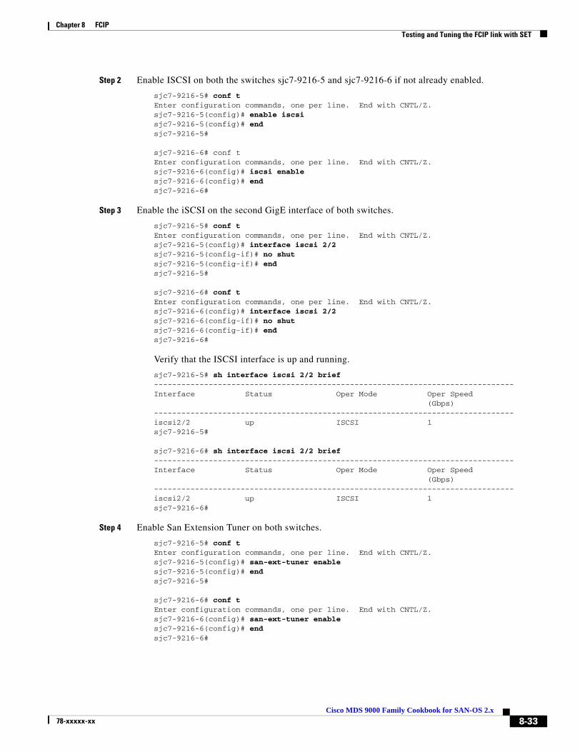
Chapter 8 FCIP Testing and Tuning the FCIP link with SET
Step 2 Enable ISCSI on both the switches sjc7-9216-5 and sjc7-9216-6 if not already enabled.
sjc7-9216-5# conf tEnter configuration commands, one per line. End with CNTL/Z.sjc7-9216-5(config)# enable iscsisjc7-9216-5(config)# endsjc7-9216-5#
sjc7-9216-6# conf tEnter configuration commands, one per line. End with CNTL/Z.sjc7-9216-6(config)# iscsi enablesjc7-9216-6(config)# endsjc7-9216-6#
Step 3 Enable the iSCSI on the second GigE interface of both switches.
sjc7-9216-5# conf tEnter configuration commands, one per line. End with CNTL/Z.sjc7-9216-5(config)# interface iscsi 2/2sjc7-9216-5(config-if)# no shutsjc7-9216-5(config-if)# endsjc7-9216-5#
sjc7-9216-6# conf tEnter configuration commands, one per line. End with CNTL/Z.sjc7-9216-6(config)# interface iscsi 2/2sjc7-9216-6(config-if)# no shutsjc7-9216-6(config-if)# endsjc7-9216-6#
Verify that the ISCSI interface is up and running.
sjc7-9216-5# sh interface iscsi 2/2 brief-------------------------------------------------------------------------------Interface Status Oper Mode Oper Speed (Gbps)-------------------------------------------------------------------------------iscsi2/2 up ISCSI 1sjc7-9216-5#
sjc7-9216-6# sh interface iscsi 2/2 brief-------------------------------------------------------------------------------Interface Status Oper Mode Oper Speed (Gbps)-------------------------------------------------------------------------------iscsi2/2 up ISCSI 1sjc7-9216-6#
Step 4 Enable San Extension Tuner on both switches.
sjc7-9216-5# conf tEnter configuration commands, one per line. End with CNTL/Z.sjc7-9216-5(config)# san-ext-tuner enablesjc7-9216-5(config)# endsjc7-9216-5#
sjc7-9216-6# conf tEnter configuration commands, one per line. End with CNTL/Z.sjc7-9216-6(config)# san-ext-tuner enablesjc7-9216-6(config)# endsjc7-9216-6#
8-33Cisco MDS 9000 Family Cookbook for SAN-OS 2.x
78-xxxxx-xx
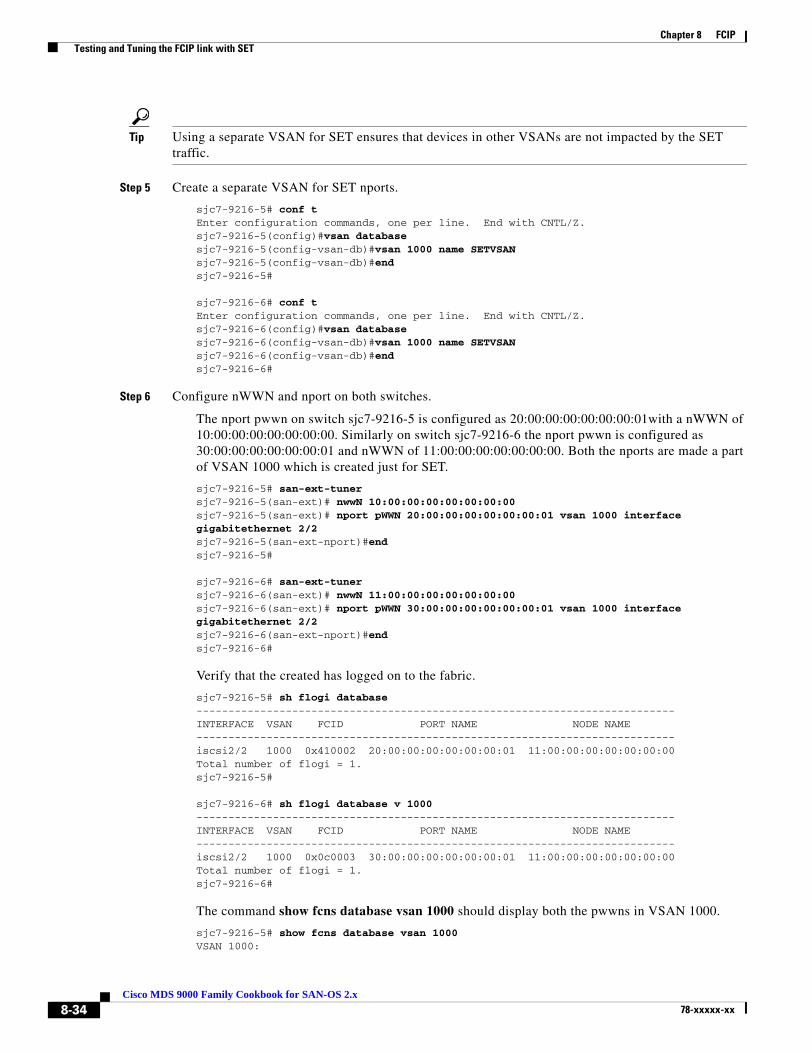
Chapter 8 FCIP Testing and Tuning the FCIP link with SET
Tip Using a separate VSAN for SET ensures that devices in other VSANs are not impacted by the SET traffic.
Step 5 Create a separate VSAN for SET nports.
sjc7-9216-5# conf tEnter configuration commands, one per line. End with CNTL/Z.sjc7-9216-5(config)#vsan databasesjc7-9216-5(config-vsan-db)#vsan 1000 name SETVSANsjc7-9216-5(config-vsan-db)#endsjc7-9216-5#
sjc7-9216-6# conf tEnter configuration commands, one per line. End with CNTL/Z.sjc7-9216-6(config)#vsan databasesjc7-9216-6(config-vsan-db)#vsan 1000 name SETVSANsjc7-9216-6(config-vsan-db)#endsjc7-9216-6#
Step 6 Configure nWWN and nport on both switches.
The nport pwwn on switch sjc7-9216-5 is configured as 20:00:00:00:00:00:00:01with a nWWN of 10:00:00:00:00:00:00:00. Similarly on switch sjc7-9216-6 the nport pwwn is configured as 30:00:00:00:00:00:00:01 and nWWN of 11:00:00:00:00:00:00:00. Both the nports are made a part of VSAN 1000 which is created just for SET.
sjc7-9216-5# san-ext-tunersjc7-9216-5(san-ext)# nwwN 10:00:00:00:00:00:00:00sjc7-9216-5(san-ext)# nport pWWN 20:00:00:00:00:00:00:01 vsan 1000 interface gigabitethernet 2/2sjc7-9216-5(san-ext-nport)#endsjc7-9216-5#
sjc7-9216-6# san-ext-tunersjc7-9216-6(san-ext)# nwwN 11:00:00:00:00:00:00:00sjc7-9216-6(san-ext)# nport pWWN 30:00:00:00:00:00:00:01 vsan 1000 interface gigabitethernet 2/2sjc7-9216-6(san-ext-nport)#endsjc7-9216-6#
Verify that the created has logged on to the fabric.
sjc7-9216-5# sh flogi database---------------------------------------------------------------------------INTERFACE VSAN FCID PORT NAME NODE NAME---------------------------------------------------------------------------iscsi2/2 1000 0x410002 20:00:00:00:00:00:00:01 11:00:00:00:00:00:00:00Total number of flogi = 1.sjc7-9216-5#
sjc7-9216-6# sh flogi database v 1000---------------------------------------------------------------------------INTERFACE VSAN FCID PORT NAME NODE NAME---------------------------------------------------------------------------iscsi2/2 1000 0x0c0003 30:00:00:00:00:00:00:01 11:00:00:00:00:00:00:00Total number of flogi = 1.sjc7-9216-6#
The command show fcns database vsan 1000 should display both the pwwns in VSAN 1000.
sjc7-9216-5# show fcns database vsan 1000VSAN 1000:
8-34Cisco MDS 9000 Family Cookbook for SAN-OS 2.x
78-xxxxx-xx
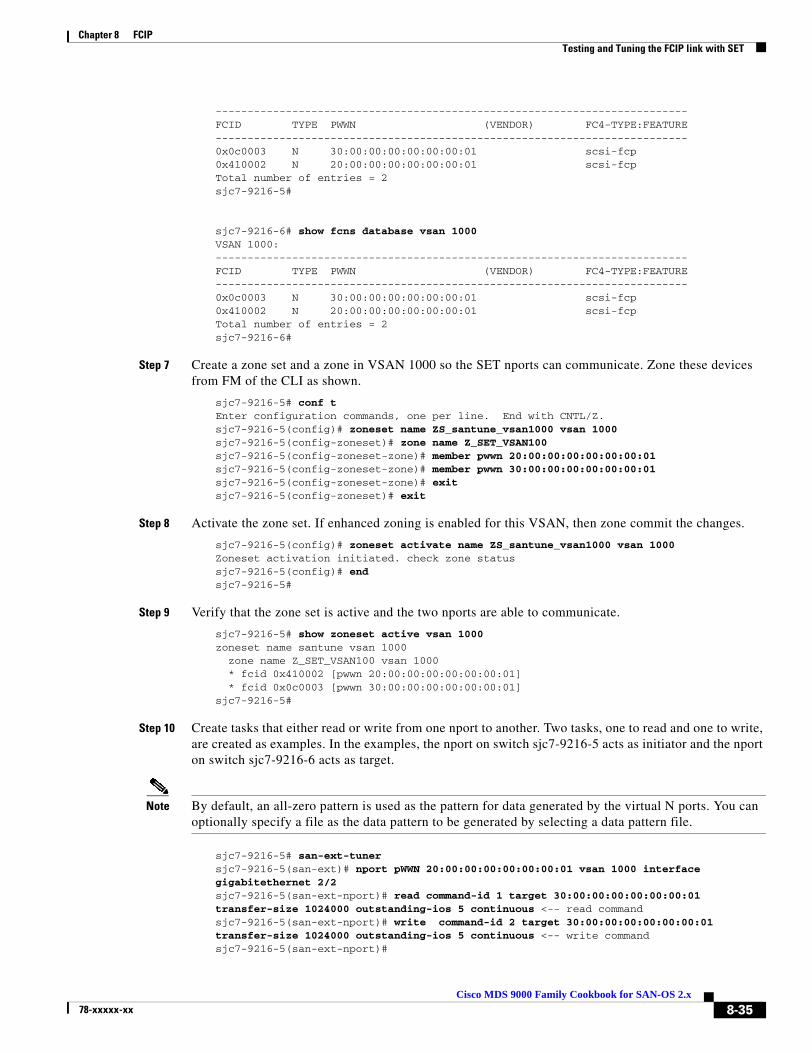
Chapter 8 FCIP Testing and Tuning the FCIP link with SET
--------------------------------------------------------------------------FCID TYPE PWWN (VENDOR) FC4-TYPE:FEATURE--------------------------------------------------------------------------0x0c0003 N 30:00:00:00:00:00:00:01 scsi-fcp0x410002 N 20:00:00:00:00:00:00:01 scsi-fcpTotal number of entries = 2sjc7-9216-5#
sjc7-9216-6# show fcns database vsan 1000VSAN 1000:--------------------------------------------------------------------------FCID TYPE PWWN (VENDOR) FC4-TYPE:FEATURE--------------------------------------------------------------------------0x0c0003 N 30:00:00:00:00:00:00:01 scsi-fcp0x410002 N 20:00:00:00:00:00:00:01 scsi-fcpTotal number of entries = 2sjc7-9216-6#
Step 7 Create a zone set and a zone in VSAN 1000 so the SET nports can communicate. Zone these devices from FM of the CLI as shown.
sjc7-9216-5# conf tEnter configuration commands, one per line. End with CNTL/Z.sjc7-9216-5(config)# zoneset name ZS_santune_vsan1000 vsan 1000sjc7-9216-5(config-zoneset)# zone name Z_SET_VSAN100sjc7-9216-5(config-zoneset-zone)# member pwwn 20:00:00:00:00:00:00:01sjc7-9216-5(config-zoneset-zone)# member pwwn 30:00:00:00:00:00:00:01sjc7-9216-5(config-zoneset-zone)# exitsjc7-9216-5(config-zoneset)# exit
Step 8 Activate the zone set. If enhanced zoning is enabled for this VSAN, then zone commit the changes.
sjc7-9216-5(config)# zoneset activate name ZS_santune_vsan1000 vsan 1000Zoneset activation initiated. check zone statussjc7-9216-5(config)# endsjc7-9216-5#
Step 9 Verify that the zone set is active and the two nports are able to communicate.
sjc7-9216-5# show zoneset active vsan 1000zoneset name santune vsan 1000 zone name Z_SET_VSAN100 vsan 1000 * fcid 0x410002 [pwwn 20:00:00:00:00:00:00:01] * fcid 0x0c0003 [pwwn 30:00:00:00:00:00:00:01]sjc7-9216-5#
Step 10 Create tasks that either read or write from one nport to another. Two tasks, one to read and one to write, are created as examples. In the examples, the nport on switch sjc7-9216-5 acts as initiator and the nport on switch sjc7-9216-6 acts as target.
Note By default, an all-zero pattern is used as the pattern for data generated by the virtual N ports. You can optionally specify a file as the data pattern to be generated by selecting a data pattern file.
sjc7-9216-5# san-ext-tunersjc7-9216-5(san-ext)# nport pWWN 20:00:00:00:00:00:00:01 vsan 1000 interface gigabitethernet 2/2sjc7-9216-5(san-ext-nport)# read command-id 1 target 30:00:00:00:00:00:00:01 transfer-size 1024000 outstanding-ios 5 continuous <-- read command sjc7-9216-5(san-ext-nport)# write command-id 2 target 30:00:00:00:00:00:00:01 transfer-size 1024000 outstanding-ios 5 continuous <-- write commandsjc7-9216-5(san-ext-nport)#
8-35Cisco MDS 9000 Family Cookbook for SAN-OS 2.x
78-xxxxx-xx
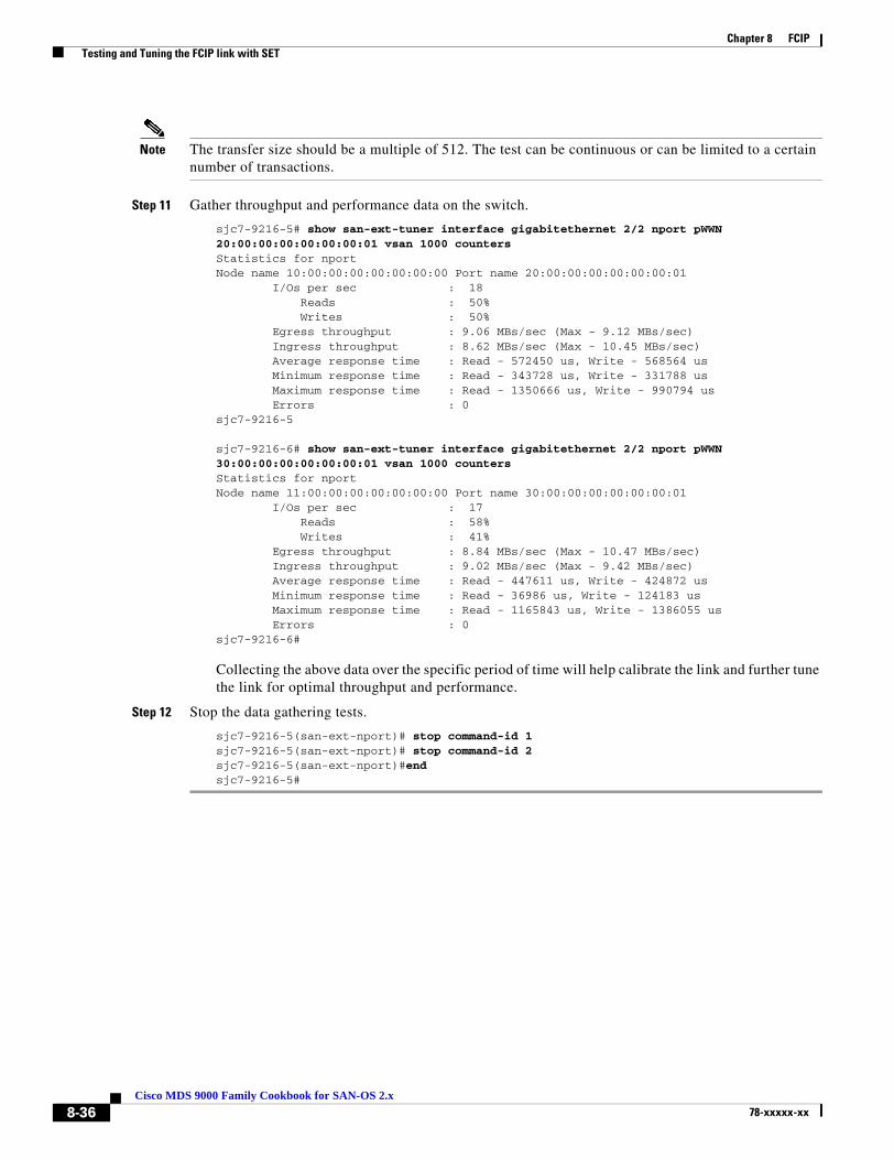
Chapter 8 FCIP Testing and Tuning the FCIP link with SET
Note The transfer size should be a multiple of 512. The test can be continuous or can be limited to a certain number of transactions.
Step 11 Gather throughput and performance data on the switch.
sjc7-9216-5# show san-ext-tuner interface gigabitethernet 2/2 nport pWWN 20:00:00:00:00:00:00:01 vsan 1000 countersStatistics for nportNode name 10:00:00:00:00:00:00:00 Port name 20:00:00:00:00:00:00:01 I/Os per sec : 18 Reads : 50% Writes : 50% Egress throughput : 9.06 MBs/sec (Max - 9.12 MBs/sec) Ingress throughput : 8.62 MBs/sec (Max - 10.45 MBs/sec) Average response time : Read - 572450 us, Write - 568564 us Minimum response time : Read - 343728 us, Write - 331788 us Maximum response time : Read - 1350666 us, Write - 990794 us Errors : 0sjc7-9216-5
sjc7-9216-6# show san-ext-tuner interface gigabitethernet 2/2 nport pWWN 30:00:00:00:00:00:00:01 vsan 1000 countersStatistics for nportNode name 11:00:00:00:00:00:00:00 Port name 30:00:00:00:00:00:00:01 I/Os per sec : 17 Reads : 58% Writes : 41% Egress throughput : 8.84 MBs/sec (Max - 10.47 MBs/sec) Ingress throughput : 9.02 MBs/sec (Max - 9.42 MBs/sec) Average response time : Read - 447611 us, Write - 424872 us Minimum response time : Read - 36986 us, Write - 124183 us Maximum response time : Read - 1165843 us, Write - 1386055 us Errors : 0sjc7-9216-6#
Collecting the above data over the specific period of time will help calibrate the link and further tune the link for optimal throughput and performance.
Step 12 Stop the data gathering tests.
sjc7-9216-5(san-ext-nport)# stop command-id 1sjc7-9216-5(san-ext-nport)# stop command-id 2sjc7-9216-5(san-ext-nport)#endsjc7-9216-5#
8-36Cisco MDS 9000 Family Cookbook for SAN-OS 2.x
78-xxxxx-xx
Cisco MDS 9078-xxxxx-xx
C H A P T E R 9
iSCSIiSCSI is a transport protocol used to transport SCSI packets over TCP/IP. It is an internet protocol-based standard that allows hosts to connect and to access storage over a network interface card. iSCSI is used to transfer data over intranets and to manage storage over long distances. Since iSCSI runs over IP, it can be used to transmit data over a LAN, WAN, MAN and so on, thereby enabling data access independent of the storage sub system location. The MDS 9200 and 9500 series switches support iSCSI using the IPS-8, IPS-4 and the 14+2 blades.
Enabling iSCSIEnable iSCSI before attempting to configure it on the switch.
Caution If you don’t execute the iSCSI enable command, further iSCSI configuration is not possible. This command enables any further iSCSI configuration options in the CLI.
sjc7-9509-5# conf tEnter configuration commands, one per line. End with CNTL/Z.sjc7-9509-5(config)# iscsi enablesjc7-9509-5(config)# endsjc7-9509-5#
9-100 Family Cookbook for SAN-OS 2.x

Chapter 9 iSCSI Configuring iSCSI on an MDS Switch in Transparent Mode
Configuring iSCSI on an MDS Switch in Transparent ModeThis recipe shows the configuration of iSCSI on the MDS switch. Transparent mode configures an equivalent fibre channel initiator for each iSCSI initiator. In this process, no lun masking or reassignment is done on the switch. For larger installations, iSCSI should be configured using the proxy initiator mode, see Configuring iSCSI on the MDS Switch in Proxy initiator mode, page 9-7.
The topology for this recipe is illustrated in Figure 9-1.
Figure 9-1 iSCSI topology.
The topology consists of a Windows 2003 server using a gigabit ethernet NIC for iSCSI. It is connected to a port on the catalyst 6509. The iSCSI interface on the host is assigned the IP address 172.22.38.45. The IPS port 8/1 on the switch sjc7-9509-5 is also connected to the Catalyst and has the IP address 172.22.34.83. The storage port from the array is connected to the FC port 1/16 on sjc7-9509-5. This example shows how to configure an iSCSI initiator using iqn (iSCSI qualified name).
Caution The IP address for the ports on the ips blade should be in a different subnet than the management interface. This is critical for iSCSI to work on the switch.
To configure iSCSI initiator on the MS switch, follow these steps:
Step 1 Configure the gigE interface on the MDS switch.
The gigE interface on the MDS switch is given an IP address and a subnetmask. This allows the gigE interface to communicate with the network.
sjc7-9509-5# conf tEnter configuration commands, one per line. End with CNTL/Z.sjc7-9509-5(config)# interface gigabitethernet 8/1sjc7-9509-5(config-if)# ip address 172.22.34.83 255.255.254.0sjc7-9509-5(config-if)# endsjc7-9509-5#
Step 2 Configure IP routes as required.
In the recipe, the initiator sjc7-pc-1 is in the 172.22.38.0 subnet while the gigE interface is in the 172.22.34.0 sub net. In order to allow the initiator and the gigE port to communicate, an IP route has to be configured on the switch.
sjc7-9509-5# conf tEnter configuration commands, one per line. End with CNTL/Z.sjc7-9509-5(config)#ip route 172.22.38.45 255.255.255.255 172.22.34.1 interface gigabitethernet 8/1sjc7-9509-5(config)# endsjc7-9509-5#
Note It is critical to check the connectivity between the host NIC card and the gigE port on the switch’s IPS blade before proceeding further. A ping test is sufficient.
9-2Cisco MDS 9000 Family Cookbook for SAN-OS 2.x
78-xxxxx-xx
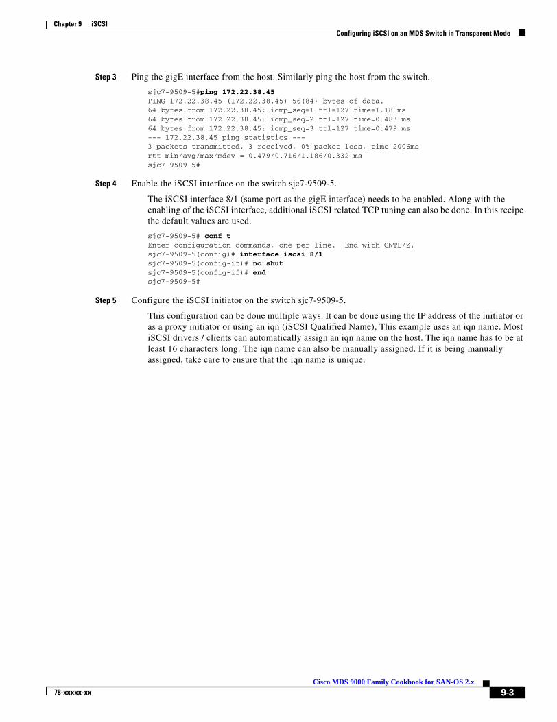
Chapter 9 iSCSI Configuring iSCSI on an MDS Switch in Transparent Mode
Step 3 Ping the gigE interface from the host. Similarly ping the host from the switch.
sjc7-9509-5#ping 172.22.38.45PING 172.22.38.45 (172.22.38.45) 56(84) bytes of data.64 bytes from 172.22.38.45: icmp_seq=1 ttl=127 time=1.18 ms64 bytes from 172.22.38.45: icmp_seq=2 ttl=127 time=0.483 ms64 bytes from 172.22.38.45: icmp_seq=3 ttl=127 time=0.479 ms--- 172.22.38.45 ping statistics ---3 packets transmitted, 3 received, 0% packet loss, time 2006msrtt min/avg/max/mdev = 0.479/0.716/1.186/0.332 mssjc7-9509-5#
Step 4 Enable the iSCSI interface on the switch sjc7-9509-5.
The iSCSI interface 8/1 (same port as the gigE interface) needs to be enabled. Along with the enabling of the iSCSI interface, additional iSCSI related TCP tuning can also be done. In this recipe the default values are used.
sjc7-9509-5# conf tEnter configuration commands, one per line. End with CNTL/Z.sjc7-9509-5(config)# interface iscsi 8/1sjc7-9509-5(config-if)# no shutsjc7-9509-5(config-if)# endsjc7-9509-5#
Step 5 Configure the iSCSI initiator on the switch sjc7-9509-5.
This configuration can be done multiple ways. It can be done using the IP address of the initiator or as a proxy initiator or using an iqn (iSCSI Qualified Name), This example uses an iqn name. Most iSCSI drivers / clients can automatically assign an iqn name on the host. The iqn name has to be at least 16 characters long. The iqn name can also be manually assigned. If it is being manually assigned, take care to ensure that the iqn name is unique.
9-3Cisco MDS 9000 Family Cookbook for SAN-OS 2.x
78-xxxxx-xx

Chapter 9 iSCSI Configuring iSCSI on an MDS Switch in Transparent Mode
The win2k server used in the Microsoft driver pre-configures the iqn name during installation. You can look up this name. In the iSCSI utility select Initiator Settings to see the iqn name for the host. The driver assigned initiator node name is iqn.1991-05.com.microsoft:sjc7-pc-1 (see Figure 9-2).
Figure 9-2 iSCSI Initiator Properties
Figure 9-2 shows the iqn name in the iSCSI driver interface highlighted in red. For the Linux OS, this information is found in the /etc/initiatorname.iscsi file. You need this information to configure the iSCSI initiator on the switch.sjc7-9509-5# conf tEnter configuration commands, one per line. End with CNTL/Z.sjc7-9509-5(config)# iscsi initiator name iqn.1991-05.com.microsoft:sjc7-pc-1 sjc7-9509-5(config-(iscsi-init))# static pWWN system-assign 1 <-- system assignedsjc7-9509-5(config-(iscsi-init))# vsan 1 <-- Must be a member in the Targets VSANsjc7-9509-5(config-(iscsi-init))# endsjc7-9509-5#
Tip If an iSCSI initiator needs to have the same pWWN previously used by a host, for example if you were converting a host from fibre channel to iSCSI, assign the pWWN manually with the commands below. This alleviates the need to modify the lun masking database on the array.
sjc7-9509-5# conf tEnter configuration commands, one per line. End with CNTL/Z.sjc7-9509-5(config)# iscsi initiator name iqn.1991-05.com.microsoft.sjc7-pc-1sjc7-9509-5(config-iscsi-init)# static pWWN 21:05:00:0d:ec:02:2d:82 <-- manually assignedsjc7-9509-5(config-iscsi-init)# vsan 1 <-- Must be a member of the Target VSANsjc7-9509-5(config-iscsi-init)# endsjc7-9509-5#
9-4Cisco MDS 9000 Family Cookbook for SAN-OS 2.x
78-xxxxx-xx

Chapter 9 iSCSI Configuring iSCSI on an MDS Switch in Transparent Mode
Here, the iqn assigned by the driver is used. If it needs to be changed make sure that the new name is unique and is at least 16 characters long. Optionally a pWWN can also be assigned to the initiator. The pWWN can be statically assigned by the administrator as shown above or the system can automatically assign one. The initiator can be part of multiple VSANs. In order to talk to the target, it has to be a member of the target’s VSAN. In the example above the target belongs to VSAN 1.
Note Alternatively, you can use the IP address of the iSCSI initiator in for configuration. Assigning a static pWWN is also an option. While zoning an iSCSI interface, you can use its IP address in place of its pWWN or iqn name.
An example of the using IP address is shown below.
sjc7-9509-5# conf tEnter configuration commands, one per line. End with CNTL/Z.sjc7-9509-5(config)# iscsi initiator ipaddress 172.22.38.45sjc7-9509-5(config-(iscsi-init))# static pWWN system-assign 1 <-- system assignedsjc7-9509-5(config-(iscsi-init))# vsan 3003 <-- Must be a member in the Targets VSANsjc7-9509-5(config-(iscsi-init))# endsjc7-9509-5#
Note For the iSCSI initiator to communicate with a target port, the iSCSI initiator has to be a member of the target port’s VSAN. iSCSI initiators can be members of multiple VSANs.
Step 6 Configure the virtual target on the switch sjc7-9509-5.
sjc7-9509-5# config tEnter configuration commands, one per line. End with CNTL/Z.sjc7-9509-5(config)# iscsi virtual-target name iscsi-sjc7-jbod-1sjc7-9509-5(config-iscsi-tgt)# pWWN 22:00:00:20:37:5a:40:26sjc7-9509-5(config-iscsi-tgt)# endsjc7-9509-5#
The virtual target is a name assigned to the storage device. This name has to be 16 characters long. Then the pWWN of the storage port is assigned to the virtual target as shown above. This completes the configuration of a virtual target.
Step 7 Permit the initiator to communicate with the virtual target already configured.
sjc7-9509-5# conf tEnter configuration commands, one per line. End with CNTL/Z.sjc7-9509-5(config)# iscsi virtual-target name iscsi-sjc7-jbod-1sjc7-9509-5(config-iscsi-tgt)# initiator iqn.1991-05.com.microsoft.sjc7-pc-1 permitsjc7-9509-5(config-iscsi-tgt)# endsjc7-9509-5#
The virtual-target can be configured to allow all initiators to communicate with it. In the example above, the virtual-target is only configured to communicate with one initiator, iqn.1991-05.com.microsoft.sjc7-pc-1.
This permits the initiator iqn.1991-05.com.microsoft:sjc7-pc-1 to communicate with the virtual-target iscsi-sjc7-jbod-1.
9-5Cisco MDS 9000 Family Cookbook for SAN-OS 2.x
78-xxxxx-xx

Chapter 9 iSCSI Configuring iSCSI on an MDS Switch in Transparent Mode
Step 8 Next, create a zone with the initiator and the virtual target configured. Add the zone to the zone set and activate the zone set.
Create a zone with the iSCSI initiator and the virtual targets as members.This enables the initiator and the target to communicate with each other. The zone can be created either with the iqn name or with the IP address or with the pWWN that was assigned to the initiator. In this recipe it is created using the pWWN.
Zoning with pWWN of the virtual-target and initiator.
sjc7-9509-5# conf tEnter configuration commands, one per line. End with CNTL/Z.sjc7-9509-5(config)# zone name Z_iscsi_tst vsan 3003sjc7-9509-5(config-zone)# mem pwwn 22:00:00:20:37:39:9c:1fsjc7-9509-5(config-zone)# mem pwwn 21:05:00:0d:ec:02:2d:82sjc7-9509-5(config-zone)#endsjc7-9509-5#
sjc7-9509-5# conf tEnter configuration commands, one per line. End with CNTL/Z.sjc7-9509-5(config)# zoneset name ZS_ISCSI vsan 3003sjc7-9509-5(config-zoneset)#member Z_iscsi_tstsjc7-9509-5(config-zoneset)endsjc7-9509-5#
Alternatively: Zoning with the pWWN of the virtual target and the iqn of the iSCSI initiator.
sjc7-9509-5# conf tEnter configuration commands, one per line. End with CNTL/Z.sjc7-9509-5(config)# zone name Z_iscsi_tst vsan 3003sjc7-9509-5(config-zone)# member pwwn 22:00:00:20:37:39:9c:1fsjc7-9509-5(config-zone)# member symbolic-nodename iqn.1991-05.com.microsoft:sjc7-pc-1sjc7-9509-5(config-zone)# endsjc7-9509-5#
Activate the zone set to allow the zone members to communicate.
sjc7-9509-5# conf tEnter configuration commands, one per line. End with CNTL/Z.sjc7-9509-5(config)# zoneset activate name ZS_ISCSI vsan 3003Zoneset activation initiated. check zone statussjc7-9509-5#
9-6Cisco MDS 9000 Family Cookbook for SAN-OS 2.x
78-xxxxx-xx
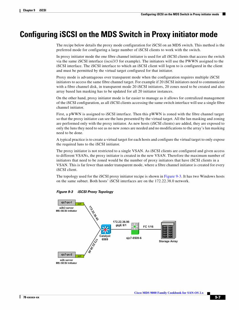
Chapter 9 iSCSI Configuring iSCSI on the MDS Switch in Proxy initiator mode
Configuring iSCSI on the MDS Switch in Proxy initiator modeThe recipe below details the proxy mode configuration for iSCSI on an MDS switch. This method is the preferred mode for configuring a large number of iSCSI clients to work with the switch.
In proxy initiator mode the one fibre channel initiator is used for all iSCSI clients that access the switch via the same iSCSI interface (iscsi3/3 for example). The initiators will use the PWWN assigned to the iSCSI interface. The iSCSI interface to which an iSCSI client will logon to is configured in the client and must be permitted by the virtual target configured for that initiator.
Proxy mode is advantageous over transparent mode when the configuration requires multiple iSCSI initiators to access the same fibre channel target. For example if 20 iSCSI initiators need to communicate with a fibre channel disk, in transparent mode 20 iSCSI initiators, 20 zones need to be created and also array based lun masking has to be updated for all 20 initiator instances.
On the other hand, proxy initiator mode is far easier to manage as it allows for centralized management of the iSCSI configuration, as all iSCSI clients accessing the same switch interface will use a single fibre channel initiator.
First, a pWWN is assigned to iSCSI interface. Then this pWWN is zoned with the fibre channel target so that the proxy initiator can see the luns presented by the virtual target. All the lun masking and zoning are performed only with the proxy initiator. As new hosts (iSCSI clients) are added, they are exposed to only the luns they need to see as no new zones are needed and no modifications to the array’s lun masking need to be done.
A typical practice is to create a virtual target for each hosts and configure the virtual target to only expose the required luns to the iSCSI initiator.
The proxy initiator is not restricted to a single VSAN. As iSCSI clients are configured and given access to different VSANs, the proxy initiator is created in the new VSAN. Therefore the maximum number of initiators that need to be zoned would be the number of proxy initiators that have iSCSI clients in a VSAN. This is far fewer than under transparent mode, where a fibre channel initiator is created for every iSCSI client.
The topology used for the iSCSI proxy initiator recipe is shown in Figure 9-3. It has two Windows hosts on the same subnet. Both hosts’ iSCSI interfaces are on the 172.22.38.0 network.
Figure 9-3 iSCSI Proxy Topology
9-7Cisco MDS 9000 Family Cookbook for SAN-OS 2.x
78-xxxxx-xx

Chapter 9 iSCSI Configuring iSCSI on the MDS Switch in Proxy initiator mode
To configure proxy mode for iSCSI on an MDS switch, follow these steps:
Step 1 Configure the gigE interface on the MDS switch.
The gigE interface on the MDS switch is given an IP address and a subnet mask. This allows the gigE interface to communicate with the network.
sjc7-9509-6# conf tEnter configuration commands, one per line. End with CNTL/Z.sjc7-9509-6(config)# interface gigabitethernet 8/1sjc7-9509-6(config-if)# ip address 172.22.36.98 255.255.254.0sjc7-9509-6(config-if)# endsjc7-9509-6#
Step 2 Configure IP routes if required.
In the recipe, the initiators sjc7-pc-1 and sjc7-pc-2 are in the 172.22.38.0 subnet while the gigE interface is in the 172.22.36.0 sub net. In order to allow the initiator and the gigE port to communicate, an IP route has to be configured on the switch. A host-based route is configured to allow the gigE port to communicate with sjc7-pc-1 and sjc7-pc-2 hosts.
sjc7-9509-6# conf tEnter configuration commands, one per line. End with CNTL/Z.sjc7-9509-6(config)# ip route 172.22.38.45 255.255.255.255 172.22.36.1 interface gigabitethernet 8/1sjc7-9509-6(config)# ip route 172.22.38.46 255.255.255.255 172.22.36.1 interface gigabitethernet 8/1sjc7-9509-6(config)# endsjc7-9509-6#
Step 3 Ping the gigE interface from the hosts. Similarly ping the host from the switch.
sjc7-9509-6#ping 172.22.38.45PING 172.22.38.45 (172.22.38.45) 56(84) bytes of data.64 bytes from 172.22.38.45: icmp_seq=1 ttl=127 time=1.18 ms64 bytes from 172.22.38.45: icmp_seq=2 ttl=127 time=0.483 ms64 bytes from 172.22.38.45: icmp_seq=3 ttl=127 time=0.479 ms--- 172.22.38.45 ping statistics ---3 packets transmitted, 3 received, 0% packet loss, time 2006msrtt min/avg/max/mdev = 0.479/0.716/1.186/0.332 mssjc7-9509-6#
sjc7-9509-6#ping 172.22.38.46PING 172.22.38.45 (172.22.38.45) 56(84) bytes of data.64 bytes from 172.22.38.46: icmp_seq=1 ttl=127 time=1.18 ms64 bytes from 172.22.38.46: icmp_seq=2 ttl=127 time=0.483 ms64 bytes from 172.22.38.46: icmp_seq=3 ttl=127 time=0.479 ms--- 172.22.38.46 ping statistics ---3 packets transmitted, 3 received, 0% packet loss, time 2006msrtt min/avg/max/mdev = 0.479/0.716/1.186/0.332 mssjc7-9509-6#
9-8Cisco MDS 9000 Family Cookbook for SAN-OS 2.x
78-xxxxx-xx
Chapter 9 iSCSI Configuring iSCSI on the MDS Switch in Proxy initiator mode
Step 4 Enable the iSCSI interface on the switch sjc7-9509-6.
The iSCSI interface 8/1 (same port as the gigE interface) needs to be enabled. Along with the enabling of the iSCSI interface, additional iSCSI related TCP tunning can also be done. In this recipe default values are used. The switch port command is used to enable proxy-initiator mode for the iSCSI interface 8/1. It is also used to assign a pWWN to the interface.
sjc7-9509-6# conf tEnter configuration commands, one per line. End with CNTL/Z.sjc7-9509-6(config)# interface iscsi 8/1sjc7-9509-6(config-if)# switchport proxy-initiator nWWN 21:05:00:0d:ec:02:2d:82 pwwn 21:05:00:0d:ec:02:2d:82sjc7-9509-6(config-if)# no shutsjc7-9509-6(config-if)# endsjc7-9509-6#
Step 5 Add the iSCSI interface to the required VSANs.
Do this to allow the iSCSI interface to communicate with the virtual target to see the luns in different VSANs. The commands below add the iSCSI interface 8/1 into the 3003 VSAN. This is VSAN to which the FC target is connected. Once this is done the interface iSCSI 8/1 will log on to the fabric.
sjc7-9509-6# conf tEnter configuration commands, one per line. End with CNTL/Z.sjc7-9509-6(config)# iscsi interface vsan-membership sjc7-9509-6(config)# vsan database sjc7-9509-6(config-vsan-db)# vsan 3003 interface iscsi 8/1sjc7-9509-6(config-vsan-db)#endsjc7-9509-6#
Note The command iscsi interface vsan-membership is required to make the iSCSI interface part of VSAN.
Step 6 Configure a virtual target on the switch sjc7-9509-6.
sjc7-9509-6# config tEnter configuration commands, one per line. End with CNTL/Z.sjc7-9509-6(config)# iscsi virtual-target name sjc7-jbod-iscsi-1sjc7-9509-6(config-iscsi-tgt)# pWWN 22:00:00:20:37:39:9c:1fsjc7-9509-6(config-iscsi-tgt)# endsjc7-9509-6#
The virtual target is a name assigned to the storage device. This name has to be 16 characters long. Then the pWWN of the storage port is assigned to the virtual target as shown above. This completes the configuration of a virtual target.
9-9Cisco MDS 9000 Family Cookbook for SAN-OS 2.x
78-xxxxx-xx
Chapter 9 iSCSI Configuring iSCSI on the MDS Switch in Proxy initiator mode
Step 7 Create a zone with the initiator and the virtual target configured. Add the zone to the zone set and activate the zone set.
Create a zone with the iSCSI initiator and virtual targets as members. This enables the initiator and the target to communicate with each other. The zone can be created either with the iqn name, IP address, or pWWN assigned to the initiator. In this recipe, it is created using the pWWN.
sjc7-9509-6# conf tEnter configuration commands, one per line. End with CNTL/Z.sjc7-9509-6(config)# zone name Z_iscsi_tst vsan 3003sjc7-9509-6(config-zone)# mem pwwn 22:00:00:20:37:39:9c:1fsjc7-9509-6(config-zone)# mem pwwn 21:05:00:0d:ec:02:2d:82sjc7-9509-6(config-zone)#endsjc7-9509-6#
sjc7-9509-6# conf tEnter configuration commands, one per line. End with CNTL/Z.sjc7-9509-6(config)# zoneset name ZS_ISCSI vsan 3003sjc7-9509-6(config-zoneset)#member Z_iscsi_tstsjc7-9509-6(config-zoneset)endsjc7-9509-6#
Activate the zone set to allow the zone members to communicate.
sjc7-9509-6# conf tEnter configuration commands, one per line. End with CNTL/Z.sjc7-9509-6(config)# zoneset activate name ZS_ISCSI vsan 3003Zoneset activation initiated. check zone statussjc7-9509-6#sjc7-9509-6# show zoneset active vsan 3003zoneset name ZS_iscsi vsan 3003 zone name Z_iscsi_proxy_8-1 vsan 3003 * fcid 0xd90002 [pwwn 21:05:00:0d:ec:02:2d:82] * fcid 0xd90000 [pwwn 22:00:00:20:37:39:9c:1f]sjc7-9509-6#
Tip To achieve lun security, create a virtual target with access to specific luns for each initiator.
Step 8 Configure a virtual target for each initiator and configure lun masking for the initiator.
Once the zone is successfully activated, the luns made available on the storage port are visible to the iSCSI interface. As this interface could be a proxy iSCSI interface for many iSCSI initiators, some form of lun security must be enabled. This recipe creates a virtual target with access to specific luns for each initiator. The iSCSI interface can see 10 luns (lun 11 to lun 20 in decimal). The configuration allows the host sjc7-pc-1 to see luns 11 - 14 (decimal) on the array.
sjc7-9509-6# config tEnter configuration commands, one per line. End with CNTL/Z.sjc7-9509-6(config)# iscsi virtual-target name sjc7-jbod-iscsi-1sjc7-9509-6(config-(iscsi-tgt))# pwwN 22:00:00:20:37:39:9c:1f fc-lun b iscsi-lun 1sjc7-9509-6(config-(iscsi-tgt))# pwwN 22:00:00:20:37:39:9c:1f fc-lun b iscsi-lun 2sjc7-9509-6(config-(iscsi-tgt))# pwwN 22:00:00:20:37:39:9c:1f fc-lun d iscsi-lun 3sjc7-9509-6(config-(iscsi-tgt))# pwwN 22:00:00:20:37:39:9c:1f fc-lun e iscsi-lun 4sjc7-9509-6(config-(iscsi-tgt))# initiator ip address 172.22.38.45 permit sjc7-9509-6(config-(iscsi-tgt))# endsjc7-9509-6#
9-10Cisco MDS 9000 Family Cookbook for SAN-OS 2.x
78-xxxxx-xx
Chapter 9 iSCSI Configuring iSCSI on the MDS Switch in Proxy initiator mode
Allow the host sjc7-pc-2 to see luns 16 - 20 (decimal).
sjc7-9509-6# config tEnter configuration commands, one per line. End with CNTL/Z.sjc7-9509-6(config)# iscsi virtual-target name sjc7-jbod-iscsi-1sjc7-9509-6(config-(iscsi-tgt))# pwwN 22:00:00:20:37:39:9c:1f fc-lun 10 iscsi-lun 1sjc7-9509-6(config-(iscsi-tgt))# pwwN 22:00:00:20:37:39:9c:1f fc-lun 11 iscsi-lun 2sjc7-9509-6(config-(iscsi-tgt))# pwwN 22:00:00:20:37:39:9c:1f fc-lun 12 iscsi-lun 3sjc7-9509-6(config-(iscsi-tgt))# pwwN 22:00:00:20:37:39:9c:1f fc-lun 13 iscsi-lun 4sjc7-9509-6(config-(iscsi-tgt))# pwwN 22:00:00:20:37:39:9c:1f fc-lun 14 iscsi-lun 5sjc7-9509-6(config-(iscsi-tgt))# initiator ip address 172.22.38.46 permit sjc7-9509-6(config-(iscsi-tgt))# endsjc7-9509-6#
After these changes, both hosts are able to see the luns allocated to them through the virtual -target created for each. There is no need to create additional zones when new iSCSI clients are added. If the iSCSI clients need access, zone additional targets to the iSCSI interfaces as shown in Step 7 of Configuring iSCSI on the MDS Switch in Proxy initiator mode.
9-11Cisco MDS 9000 Family Cookbook for SAN-OS 2.x
78-xxxxx-xx
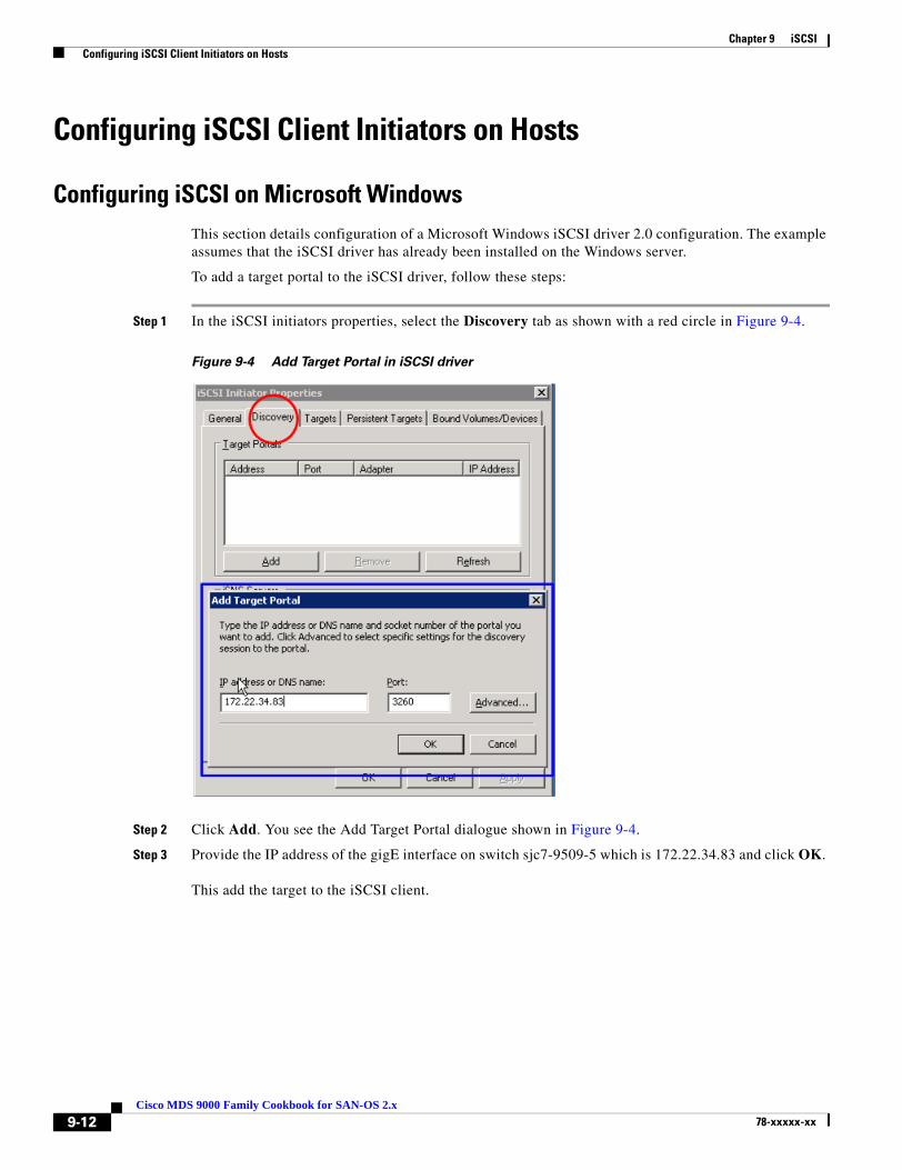
Chapter 9 iSCSI Configuring iSCSI Client Initiators on Hosts
Configuring iSCSI Client Initiators on Hosts
Configuring iSCSI on Microsoft WindowsThis section details configuration of a Microsoft Windows iSCSI driver 2.0 configuration. The example assumes that the iSCSI driver has already been installed on the Windows server.
To add a target portal to the iSCSI driver, follow these steps:
Step 1 In the iSCSI initiators properties, select the Discovery tab as shown with a red circle in Figure 9-4.
Figure 9-4 Add Target Portal in iSCSI driver
Step 2 Click Add. You see the Add Target Portal dialogue shown in Figure 9-4.
Step 3 Provide the IP address of the gigE interface on switch sjc7-9509-5 which is 172.22.34.83 and click OK.
This add the target to the iSCSI client.
9-12Cisco MDS 9000 Family Cookbook for SAN-OS 2.x
78-xxxxx-xx
Chapter 9 iSCSI Configuring iSCSI Client Initiators on Hosts
Step 4 Use the show fcns database command to show the iSCSI initiator logged onto the fabric in the specified VSAN, in this case VSAN 3003.
If the initiator does not appear in the output, make sure the initiator is properly configured.
The output in brackets (like [dev1-1]) shows Device Aliases. See Device Aliases, page 1-45 for more information.
sjc7-9509-5# show fcns database vsan 3003VSAN 3003:--------------------------------------------------------------------------FCID TYPE PWWN (VENDOR) FC4-TYPE:FEATURE--------------------------------------------------------------------------0x900002 N 21:05:00:0d:ec:02:2d:82 (Cisco) scsi-fcp:init isc.w0xd900cb NL 22:00:00:20:37:39:9c:1f (Seagate) scsi-fcp:target [dev1-1]0xd900cd NL 22:00:00:20:37:38:84:9e (Seagate) scsi-fcp:target [dev3-1]0xd900ce NL 22:00:00:20:37:18:16:c9 (Seagate) scsi-fcp:target [dev5-1]0xd900d1 NL 22:00:00:20:37:38:7c:a4 (Seagate) scsi-fcp:target [dev6-2]0xd900d2 NL 22:00:00:20:37:36:00:92 (Seagate) scsi-fcp:target [dev4-1]0xd900d4 NL 22:00:00:20:37:5a:40:26 (Seagate) scsi-fcp:target [dev7-2]0xd900d5 NL 22:00:00:20:37:38:88:9c (Seagate) scsi-fcp:target [dev2-1]Total number of entries = 8sjc7-9509-5#
9-13Cisco MDS 9000 Family Cookbook for SAN-OS 2.x
78-xxxxx-xx
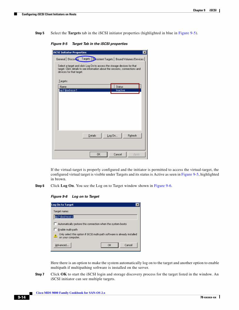
Chapter 9 iSCSI Configuring iSCSI Client Initiators on Hosts
Step 5 Select the Targets tab in the iSCSI initiator properties (highlighted in blue in Figure 9-5).
Figure 9-5 Target Tab in the iSCSI properties
If the virtual-target is properly configured and the initiator is permitted to access the virtual-target, the configured virtual target is visible under Targets and its status is Active as seen in Figure 9-5, highlighted in brown.
Step 6 Click Log On. You see the Log on to Target window shown in Figure 9-6.
Figure 9-6 Log on to Target
Here there is an option to make the system automatically log on to the target and another option to enable multipath if multipathing software is installed on the server.
Step 7 Click OK to start the iSCSI login and storage discovery process for the target listed in the window. An iSCSI initiator can see multiple targets.
9-14Cisco MDS 9000 Family Cookbook for SAN-OS 2.x
78-xxxxx-xx
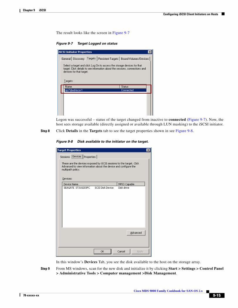
Chapter 9 iSCSI Configuring iSCSI Client Initiators on Hosts
The result looks like the screen in Figure 9-7
Figure 9-7 Target Logged on status
Logon was successful – status of the target changed from inactive to connected (Figure 9-7). Now, the host sees storage available (directly assigned or available through LUN masking) to the iSCSI initiator.
Step 8 Click Details in the Targets tab to see the target properties shown in see Figure 9-8.
Figure 9-8 Disk available to the initiator on the target.
In this window’s Devices Tab, you see the disk available to the host on the storage array.
Step 9 From MS windows, scan for the new disk and initialize it by clicking Start > Settings > Control Panel > Administrative Tools > Computer management >Disk Management.
9-15Cisco MDS 9000 Family Cookbook for SAN-OS 2.x
78-xxxxx-xx

Chapter 9 iSCSI Configuring iSCSI Client Initiators on Hosts
Configuring an iSCSI Client on LinuxThis section covers the configuration you do on a Linux server for an iSCSI client. To enable iSCSI to work on a Linux host, download and configure the iSCSI driver. The link driver is currently maintained on sourceforge and can be downloaded from http://sourceforge.net/project/showfiles.php?group_id=26396&release_id=177564. In some instances, the driver may need to be compiled.
Once the driver is installed on the host, configure it by editing the iSCSI.conf file (usually present in the /etc directory on the Linux server). As with the Windows configuration, add the target portal has and configure the iSCSI initiator on the switch. Then, restart the iSCSI initiator on the Linux host to log on to the target and access the LUNs.
As with Windows iSCSI driver, the iSCSI initiator’s name is auto-generated by the driver subsystem. The auto-generated name is in the file /etc/initiatorname.iscsi.
The process of configuring the iSCSI initiator and virtual target on the MDS switch and creating zones and activating the zone set is as described in Configuring iSCSI on an MDS Switch in Transparent Mode, page 9-2.
The iSCSI initiator name is auto-generated by the iSCSI driver in Linux and stored in the file /etc/initiatorname.iscsi.
Step 1 To make iSCSI configuration changes on a Linux server, edit the file /etc/iscsi.conf. Under the DiscoverAddress Settings section, add the address of the target portal, in this case 172.22.34.83.
# DiscoveryAddress Settings# -------------------------# Add "DiscoveryAddress=xxx" entries for each iSCSI router instance.# The driver will attempt to discover iSCSI targets at that address# and make as many targets as possible available for use.# 'xxx' can be an IP address or a hostname. A TCP port number can be# specified by appending a colon and the port number to the address.# All entries have to start in column one and must not contain any# whitespace.## Example:#DiscoveryAddress=172.22.34.83
This is all that is needed to change iSCSI configured on a Linux server.
Step 2 Restart the iSCSI process.
Once the target portal address is updated, restart the iSCSI processes to force the iSCSI client to log onto the target and discover the luns. Do this with RC scripts. The RC scripts are located in the /etc/rc3.d directory in the file S25iscsi script. Run the script with a restart option after the changes to /etc/iscsi.conf are made. The script also has a status option to check the status of the iSCSI processes on the system
[root@sjc7-pc-6 rc3.d]# /etc/rc3.d/S25iscsi restartStopping iSCSI: sync umount sync iscsid iscsiStarting iSCSI: iscsi iscsid[root@sjc7-pc-6 rc3.d]# /etc/rc3.d/S25iscsi statusiSCSI driver is loaded[root@sjc7-pc-6 rc3.d]#
Now, the iSCSI initiator should log onto the target and discover the luns assigned to it.
9-16Cisco MDS 9000 Family Cookbook for SAN-OS 2.x
78-xxxxx-xx