circuits and electrical flow. the amazing image which follows shows a picture of earth taken at...
TRANSCRIPT

CIRCUITS AND ELECTRICAL FLOW

• The amazing image which follows shows a picture of earth taken at night from outer space. The street and house lights illuminate the countries and give an idea how widespread the use of electricity is all over the world. In the image, how lit up is Colombia?


So what is electricity?
• One often hears the words "current", "voltage" and "resistance". It is very important to understand these three concepts well. Let us start by explaining what electric current is.

Let us imagine that an electrical current is going through the light brown wire below.

• When we say that an electrical "current" is flowing, what is it that is actually flowing ? Current is the flow of electrons. Electrons can be thought of as negatively charged "particles". The movement of these electrons is called current.


• Let us imagine that you want to install a beautiful waterfall in your garden (also imagine that you are rich enough to have a big garden).


To save money, you decide to build what you think is a waterfall. It looks like this. ..

Unfortunately the water doesn't flow at all. You cannot understand why.
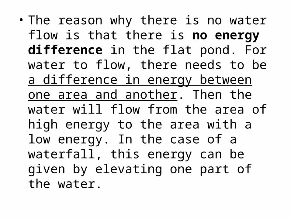
• The reason why there is no water flow is that there is no energy difference in the flat pond. For water to flow, there needs to be a difference in energy between one area and another. Then the water will flow from the area of high energy to the area with a low energy. In the case of a waterfall, this energy can be given by elevating one part of the water.

The elevated water has more energy (due to gravity) than the water at the base, making water flow.

• Let us examine this in terms of energy. In the case of the waterfall, it is gravity that determines energy. The higher the water, the more the potential energy it has.
• That is why the water in the higher tank has a higher potential energy than the lower tank. The difference in energy makes the water flow. As the water flows down the water fall, it loses potential energy. Once it reaches the bottom, it therefore has a lower potential energy than the remaining water in the upper tank.

As you admire your waterfall and show it off to your friends, you suddenly discover that it has stopped
flowing! The reason is that the higher water tank is now empty!

Once the top tank is empty, of course water won´t flow back upwards on its own.

For the same reason, if you simply connected a pipe from the lower tank to the upper tank, the water won't
go back to the higher tank

So you decide that the solution is to reuse the water and you install a water pump. The pump takes the water from the bottom and pumps it to the upper
water tank.
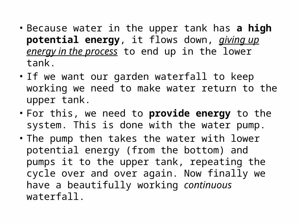
• Because water in the upper tank has a high potential energy, it flows down, giving up energy in the process to end up in the lower tank.
• If we want our garden waterfall to keep working we need to make water return to the upper tank.
• For this, we need to provide energy to the system. This is done with the water pump.
• The pump then takes the water with lower potential energy (from the bottom) and pumps it to the upper tank, repeating the cycle over and over again. Now finally we have a beautifully working continuous waterfall.


Now let us move to something electrical. Instead of having a waterfall, let us imagine that we want to light up a light bulb. A light bulb is
something that lights up when current passes through it.

Let us connect up some wires to the bulb to try and make it light up. Oh no! The bulb does not light up. We can see that the wire has electrons
in it, but the bulb does not light up.

The reason that the bulb does not light up is that there is no flow of electrons. This is similar
to the water not flowing in the level pond.

Let us see the wire in close up to see why the bulb is not lighting

• You will see that the electrons in the wire are moving randomly in all directions and are not flowing in a particular direction. You will recall that current is the flow of electrons.
• Since the electrons in the wire are all not flowing in a particular direction, there is no current passing through the bulb, and hence the bulb does not light up.


• This is similar to the situation where the waterfall did not work without a pump. The waterfall system has water, but the water is not moving, due to the lack of energy. Even if you connect a pipe between the tanks, water will not flow on its own to the upper tank.

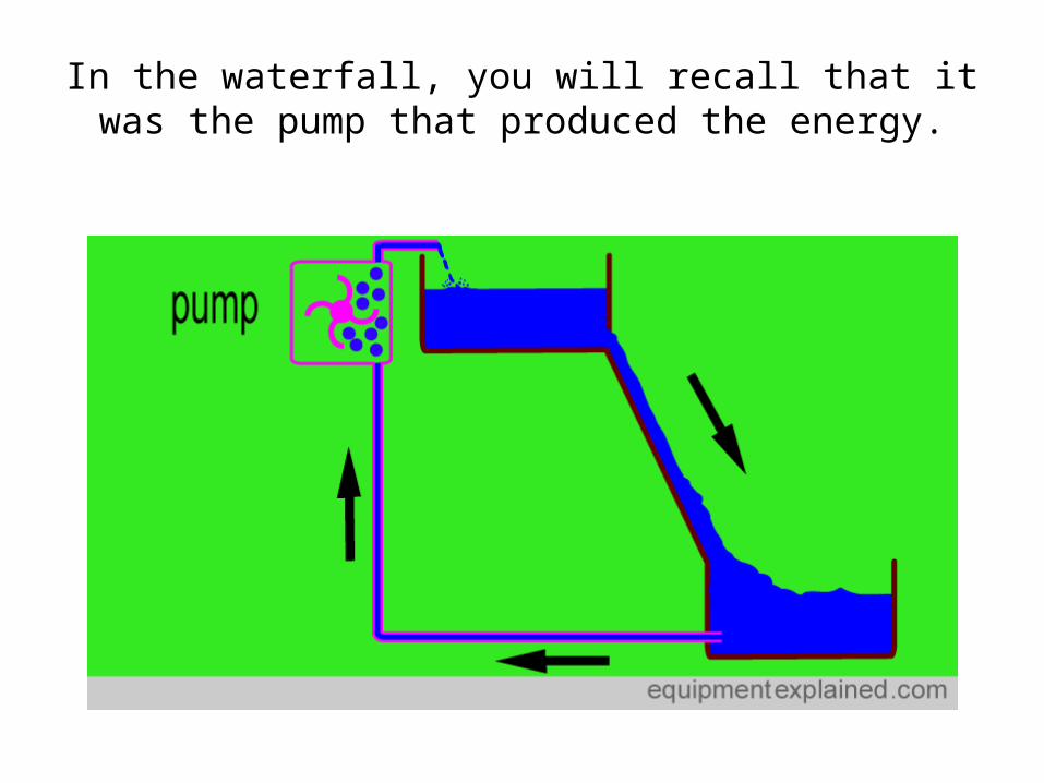
In the waterfall, you will recall that it was the pump that produced the energy.

• Just like the water in the waterfall, electrical circuits need a potential energy difference to make the current flow.
• The next image shows two wires. The upper wire has no potential difference across it. The electrons are randomly moving in all directions with no net flow. Therefore this wire is not carrying any current.
• The lower wire has a potential difference across A and B. It makes the electrons flow in a particular direction and therefore this wire is carrying a current.


• There are a variety of sources that can produce a potential difference that can make a current flow in an electrical circuit.
• You can think of a 'potential difference source' as being like the pump in the waterfall we discussed. The pump makes water flow around the system.
• In an electrical circuit, the potential difference source makes the electrons (i.e. current) flow around the circuit.

Potential difference sources have a ' negative pole' and a 'positive pole'. Current leaves the
negative pole and returns to the positive pole.

Let us discuss a common potential difference source that you may have used at home. This
source is the common disposable battery.

Let us now connect this battery to the bulb we were trying to light up before. The potential difference generated in the
battery makes the electrons move. The current goes from the negative pole, through wires to the bulb, goes through the bulb and makes it light up, and returns by wire to the positive pole.

The unit of measurement for potential difference is "volt". More the potential difference across the poles,
more is the volts.A typical house hold battery has 1.5 volts, or
abbreviated as “1.5 V” Remember: Voltage is a measurement of the potential
difference.

On the other hand, potential difference coming out of wall sockets can be quite high (e.g. 120
volts or 240 volts).

Now, drawing all this stuff can be quite tiring. Fortunately, when discussing electricity, one doesn't
have to draw the "real" thing all the time. Instead, one can use symbols. For an example, the symbol for a
battery is:

The shorter vertical line represents the negative pole.

If you really want to remember which is negative and which is positive, here is a simple memory
aide. Just remember ' n ' is shorter than ' p '

Similarly, a light bulb can be represented by either of these symbols.

While a switch (open) can be represented as:

OTHER CIRCUIT SYMBOLS…
So, what is a circuit?
• In electronics, a circuit is a path between two or more points along which an electrical current can be carried.
• A resistor is anything which resists the flow of this electrical current (anything that uses electricity to do work e.g a lightbulb).

By using these symbols, electrical circuits can be drawn much more easily than using realistic
diagrams. For an example, this circuit ....
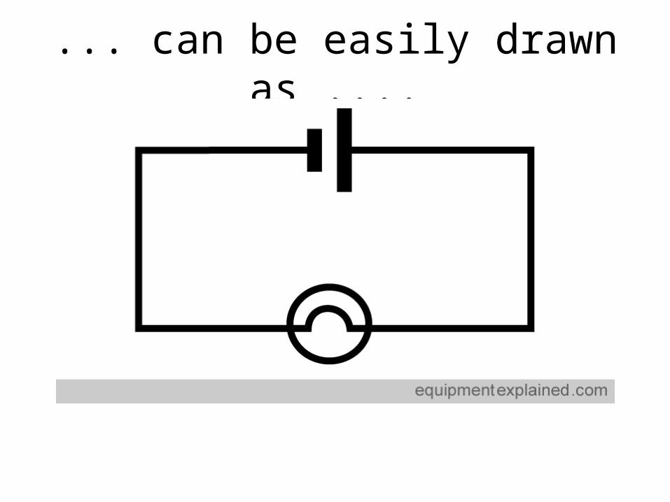
... can be easily drawn as ....

SERIES CIRCUITS

What is a series circuit?
• A series circuit has more than one resistor and gets its name from only having one path for the electrical charges to move along.
• Electrical charges must move in "series" first going to one resistor then the next and so on...
• (The next diagram show a conventional current which shows the apparent flow of positive charges around the circuit).

The electrical charges are ´pushed´ up the hill by the powersource. They then provide power to 2 (or more)
wheels (resistors) as they descend the other side…
Advantages of Series Circuits:
• You can add more power sources, like batteries, and increase the force of the output which grants you more power. In Parallel, however, the power stays at the same voltage of the original power source. For example, if you were running a circuit on a 5-volt battery and it kept the bulb going for two hours and then added another 5-volt battery, it would keep the bulbs going for four hours instead, but it would only give out 5-volts instead of increasing it to ten.

Disadvantages:• It is impossible to control the bulbs individually. This is one reason
that series circuits are not practical for use in home lighting: It is not possible to control the lights in different rooms throughout the house on the same circuit. For example, if someone wanted to read the newspaper or watch television, he would have to turn on a switch that would put on every light and electrical appliance in the whole house.
Also, in a series circuit, the more output devices you add the slower the current becomes as there is more resistance in the circuit. If these output devices were, for example, bulbs, this would mean that the brightness of the bulbs would be dimmed. Another disadvantage of a series circuit is that if a bulb were broken or the pathway broken in any way, the other bulbs would go out too.

Parallel Circuits
• A parallel circuit has more than one resistor (anything that uses electricity to do work) and gets its name from having multiple (parallel) paths to move along .
• Charges can move through any of several paths. If one of the items in the circuit is broken then no charge will move through that path, but other paths will continue to have charges flow through them.
• Parallel circuits are found in most household electrical wiring. This is done so that lights don't stop working just because you turned your TV off.

Note that more electrical charges move through the ´easier´ resistor.

Advantages of Parallel Circuits:
• (If it were light bulbs that were the output devices linked in parallel). If one bulb broke the others would continue going. Also, the brightness of the bulbs would be greater than the brightness of bulbs in series.
• In parallel, increasing the number of output devices does not increase the resistance like it does in series.

Disadvantages
• There could be a risk of fire in some cases. Another would be that, if you have multiple power sources, the power stays at the same voltage as that of the single power source.

Bibliography
• www.equipmentexplained.com• www.regentsprep.org