cia transducers, inc. · amplified square wave speed sensor theory of operation combination ofa vrs...
TRANSCRIPT

CIA Transducers, Inc.
Magnetic Speed SensorsHall Effect SensorsDigital Speed Sensors
oo
Speed Sensing
INTRODUCTION
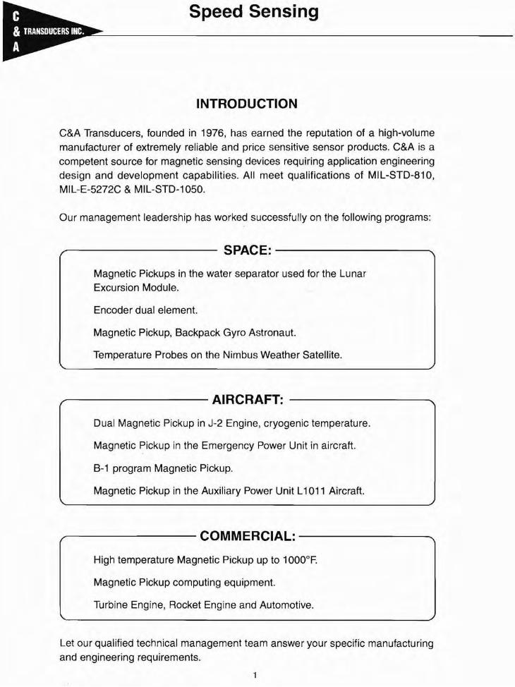
C&A Transducers, founded in 1976, has earned the reputation of a high-volumemanufacturer of extremely reliable and price sensitive sensor products. C&A is acompetent source for magnetic sensing devices requiring application engineeringdesign and development capabilities. All meet qualifications of MIL-STD-810,MIL-E-5272C & MIL-STD-1050.
Our management leadership has worked successfully on the following programs:
--------- SPACE: ----------....
Magnetic Pickups in the water separator used for the LunarExcursion Module.
Encoder dual element.
Magnetic Pickup, Backpack Gyro Astronaut.
Temperature Probes on the Nimbus Weather Satellite.
-------- AIRCRAFT:
Dual Magnetic Pickup in J-2 Engine, cryogenic temperature.
Magnetic Pickup in the Emergency Power Unit in aircraft.
B-1 program Magnetic Pickup.
Magnetic Pickup in the Auxiliary Power Unit L1011 Aircraft.
-------- COMMERCIAL: --------...
High temperature Magnetic Pickup up to 1000°F.
Magnetic Pickup computing equipment.
Turbine Engine, Rocket Engine and Automotive.
Let our qualified technical management team answer your specific manufacturingand engineering requirements.

Shown in Figure 2 are the three basic types of pole piececonfigurations. Each offers distinct advantages over theothers depending upon the application. The standard polepiece profile is cylindrical and designed for use with relativelycoarse tooth gears. In numerous applications, however, theuse of this type gear is not feasible, necessitating the use ofa modified pole piece configuration to achieve effectiveperformance. Conical and chisel tip pole pieces are usedwhen a gear has a very fine pitch, or the actuating mass isvery small. This allows for sharper output pulses and finerresolutions. Larger pole pieces in similar applications maynot provide a sufficient output voltage since a shunting effectof the magnetic field may result when the pole piece coversmore than one tooth at a time. In essence, the sensor cannotdistinguish one tooth from the next.
RPM x DIA x n:Surface Speed (IPS) =--"':"":":"'''':'':'':'''':'-'--6=0-'-'--=-''-'--"-.::--
a. Surface speed of the gear passing by the pole-pieceb. Gap between pole-piece and gear teethc. Gear Pitch or gear tooth sized. Load impedance connected to the pickup
The surface speed of a gear depends upon its diameter andRPM. All other variables remaining constant, it can be saidthat:
a. The pickup output voltage increases as the gear RPMincreases (and)
b. The pickup output voltage increases as the geardiameter increases, (therefore)
c. The pickup output voltage increases as the gear surfacespeed increases since:
C & A magnetic pickups convert mechanical motion to an acvoltage without mechanical linkage. These permanentmagnet transducers have an external magnetic field whichwhen altered by a moving ferrous object, generates an acvoltage in a coil wound over the magnet. This ac voltage hasa frequency directly proportional to RPM when the pickup ismounted in proximity to the teeth of a rotating gear. The
'magnitude of the voltage is proportional to the rate of changeof magnetic flux, therefore the voltage is proportional tospeed.
The pickup output voltage level depends on the followingvariables.
SIGNAL WIRES
Magnetic Pickups
THEORY OF OPERATION
PERMANENT MAGNETIC
Typical C & A Magnetic Pickups
Internal configuration fo typical pickup.
Fig. 1 -Magnetic pickup mounted in bracket in proximity to gear.
The engineering staff of C & A candesign and build magnetic pickups toyour specific needs. Call your localrepresentative at: 714-554-9188.
Adrian Van De ReeDan Toledo
II 'I ... iii-...regular blind chisel
Fig. 2 - View of regular, blind and chisel ends of magnetic pickups.
2

Standard Magnetic Speed Sensors
GENERAL PURPOSEsta"-18 Thread
SPECIFICATIONS - (625000 SERIES)Output Voltage: 40 (P-P MIN.)Resistance: 85 ohms (MAX.)Inductance: 25 mh (MAX.)Temperature Range: - 100°F to + 225°FPole Piece Dia. (in.): .106Shell: Stainless Steel
HIGH SENSITIVITY5/a"-18 Thread
SPECIFICATIONS - (625000-1 SERIES)Output Voltage: 190 (P-P MIN.)Resistance: 1200 ohms (MAX.)Inductance: 450 mh (MAX.)Temperature Range: - 100°F to + 225°FPole Piece Dia. (in.): .106Shell: Stainless Steel
MODEL NO. DIM. "X" DIM. "Y"
625500(-1) 5.000 6.100625600(-1 ) 6.000 7.100625300(-1) 3.000 4.100625100(-1) 1.000 2.100625400(-1) 4.000 5.100625250(-1) 2.500 3.600
"Y" DIM.
I •.025
0-000 _
750DIA. E:)±005
.106SENSING DIA
5/8-18 UNF-2A THREAD 5/8-24 UNEF-2A THREAD
NOTES: (1) Tested at 1,000 inches/second with a 20 pitch, 30 tooth gearat ,005" pole piece gap and 100 K onm load,(2) Connector mates with MS-3'106A-10SL-4S connector
• Also available in metric THD.M16x1.5-6g
3

Special Purpose Magnetic Speed Sensors
GENERAL PURPOSEBlind-End - 5/8"-18 Thread
SPECIFICATIONS - (8625000 SERIES)Output Voltage: 60 (P-P MIN.)Resistance: 200 ohms (MAX.)Inductance: 85 mh (MAX.)Temperature Range: - 100°F to + 300°FPole Piece Dia. (in.): .106Shell: Stainless Steel
HIGH SENSITIVITYBlind-End - 5/8"-18 Thread
SPECIFICATIONS - (8625000-1 SERIES)Output Voltage: 175 (P-P MIN.)Resistance: 1200 ohms (MAX.)Inductance: 450 mh (MAX.)Temperature Range: - 100°F to + 300°FPole Piece Dia. (in.): .106Shell: Stainless Steel
MODEL NO.
B625500(-1 )B625600(-1 )B625300(-1 )B6251 00(-1)B625400(-1 )B625250(-1 )
DIM. "X"
5.0006.0003.0001.0004.0002.500
DIM. "V"
6.1007.1004.1002.1005.1003.600
_-----"Y"DIM. ---_
r---- "X" DIM. ---.,
5/8-18 UNF-2A THREAD
I +.025
0- .000 _.750 DlA. ~ ~
NOTES: (1) Tested at 1,000 inches/second with a 20 pitch, 30 tooth gearat .005" pole piece gap and 100 K ohm load.(2) Connector mates with MS-3106A-10SL-4S connector
• Also available in metric THD.M16x1.5-6g
4

Standard Magnetic Speed Sensors
Full Thread - 5/s"-18UNF-2A Thread
SPECIFICATIONS - (6252000 & 6253060)Output Voltage: 40 (P-P MIN.)Resistance: 85 ohms (MAX.)Inductance: 25 mh (MAX.)Temperature Range: - 1OO°F to+ 225°FPole Piece Dia. (in.): .106Shell: Stainless Steel
SPECIFICATIONS - (6252000-1 & 6253060-1)Output Voltage: 190 (P-P MIN.)Resistance: 1500 ohms (MAX.)Inductance: 800mh (MAX.)Temperature Range: - 1000 to + 225°FPole Piece Dia. (in.): ,106Shell: Stainless Steel
MODEL NO. DIMENSION A (inches)
6252000(-1 ) 2.0006253060(-1 ) 3.060
5/8-18 UNF-2A THREAD
LOCKNUT
1--- --------T~:o~~.,.o,"=J
NO. 20 AWG. LEADS (2)VINYL INSULATION12 INCH MINIMUM
NOTES: (1) Tested at 1,000 inches/second with a 20 pitch, 30 tooth gearat .005" pole piece gap and 100 K ohm load.
5

Special Purpose Magnetic Speed Sensors
7500 Series (3/4 - 16 UNF-2A)
SPECIFICATIONSOutput Voltage: 10.0 (P-P MIN.)Resistance: 3575 ohms (MAX.)Inductance: 1250 mh (MAX.)Temperature Range: - 100°F to + 225°FPole Piece Dia. (in.): .125Shell: Stainless Steel
• Tested at 280 Inches/second with a 20 pitch, 60 tooth gear at .025 airgap and 100k ohm load.
MODEL NO. DIM. "X" DIM. lOY"
750300 3.900 3.300750200 2.970 2.370750100 2.350 1.750
--- ---.188 ± .032
16 AWG. (2 COND.)
LCABLEOR16 AWG. LEADS
?-,-_-_-_-_-_-_""'"_-_-_--:'L-
.165 ± .032
J .......1------ 72"
DIMENSION "Y" I IDIMENSION "X" J
HEX JAM-NUT
3/4·16 UNF-2A---../
6

Special Purpose Magnetic Speed Sensors
7500 Series (3/4 - 16 UNF-2A) BLIND END
SPECIFICATIONSOutput Voltage: 10.0 (P-P MIN.)Resistance: 3575 ohms (MAX.)Inductance: 1250 mh (MAX.)Temperature Range: - 100°F to + 225°FPole Piece Dia. (in.): .125Shell: Stainless Steel
• Tested at 280 inches/second with a 20 pitch, 60 tooth gear at .025 airgap and 1OOk ohm load.
MODEL NO. DIM. "X" DIM. "Y"
B750300 3.900 3.300B750200 2.970 2.370B750100 2.350 1.750
---- ---.188 ± .032
72"
16 AWG. (2 COND.)
LCABLEOR16 AWG. LEADS
------? t'---.....l....-------,5
~.165±.032
DIMENSION "Y"~J ...DIMENSION "X"
HEX JAM-NUT
3/4-16 UNF-2A ----"
7
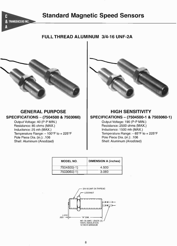
Standard Magnetic Speed Sensors
FULL THREAD ALUMINUM 3/4-16 UNF-2A
GENERAL PURPOSESPECIFICATIONS - (7504500 & 7503060)
Output Voltage: 40 (P-P MIN.)Resistance: 85 ohms (MAX.)Inductance: 25 mh (MAX-)Temperature Range: - 100°F to + 225°FPole Piece Dia. (in.): .106Shell: Aluminum (Anodized)
HIGH SENSITIVITYSPECIFICATIONS - (7504500-1 & 7503060-1)
Output Voltage: 190 (P-P MIN.)Resistance: 2500 ohms (MAX.)Inductance: 1500 mh (MAX.)Temperature Range: - 65°F to + 225°FPole Piece Dia. (in.): .106Shell: Aluminum (Anodized)
MODEL NO. DIMENSION A (inches)
7504500(-1 ) 4.5007503060(-1 ) 3.060
3/4-16 UNF-2A THREAD
LOCKNUT
1--- --------T±o~
= ~,~",:':w;I,VINYL INSULATION12 INCH MINIMUM
8

Miniature Magnetic Speed Sensors
General Purpose - 3/8 - 24
SPECIFICATIONS - (375000-1 SERIES)Output Voltage: 60 (P-P MIN.)Resistance: 1000 ohms (MAX.)Inductance: 250 mh (MAX.)Temperature Range: - 100°F to + 225°FPole Piece Dia. (in.): .093Shell: Stainless Steel
SPECIFICATIONS - (375000 SERIES)Output Voltage: 60 (P-P MIN.)Resistance: 1000 ohms (MAX.)Inductance: 250 mh (MAX.)Temperature Range: - 100°F to + 225°FPole Piece Dia. (in.): .093Shell: Stainless Steel
MODEL NO. DIM. "A"
375400-1 4.300375200-1 2.500375150-1 2.000375100-1 1.250
MODEL NO. DIM. "A" DIM. "B"
375400 4.000 4.430375200 2.270 2.700375150 1.675 2.100375100 1.000 1.430
.45 REF.
cL22AWG.2 CONDoCABLE
'-----72.00 _ILOCKNUT
THREAD SIZE: 3/8-24 UNF-2A
03~·0---+--10"A""]B"W±.010 .43
.093 REF.22 AWG.r~COND
~ABLE
- 3/8-24 UNF-2A THREADLOCKNUT
NOTE: (1) Tested at 1,000 inches/second with a 20 pitch, 30 tooth gearat .005" pole piece gap and 100 K ohm load_
9

Miniature Magnetic Speed Sensors
Full Thread - 1/4" - 401/4" - 28
SPECIFICATIONS - (MODEL 250100)Output Voltage: 12 (P-P MIN.)Resistance: 190 ohms (MAX.)Inductance: 16 mh (MAX.)Temperature Range: - 100°F to + 225°FPole Piece Dia. (in.): .040Shell: Stainless Steel
:... NO. 30 AWG. LEADS (2)VINYL INSULATION6 INCH MINIMUM
General Purpose - 1/4" - 401/4" - 28
SPECIFICATIONS - (MODEL 250650)Output Voltage: 12 (P-P MIN.)Resistance: 190 ohms (MAX.)Inductance: 16 mh (MAX.)Temperature Range: - 100°F to + 225°FPole Piece Dia. (in.): .040Shell: Stainless Steel
1/4-28 NF 2 THREAD
~/4-40 UNS 2A THREA.D
_ . __LOCKNU~265 + .010
~-- - ~1E--=~II IREF.I-
02g010
I 650 ~ NO. 30 AWG. LEADS (2). ----I f--- ----" VINYL INSULATION
6 INCH MINIMUM
NOTE: (1) Tested at 1,000 inches/second with a 20 pitch, 30 tooth gearat .005" pole piece gap and 100 K ohm load,
10

Low-Cost Magnetic Speed Sensors
ECONOMICAL I PLASTIC SENSORS
C&A Transducers offers a comprehensive line of plastic sensors for use in highvolume OEM applications where low cost is a requirement. Dimensional andelectrical specifications available upon request.
11

1/8" Pipe Threaded Magnetic Pickup
- - -- --- - ----- - -
Lz.oo" +[-0.20"1 3-WIRE 22 GA. CABLE II r:,....-------------:,.~I24" MINIMUN .
SHELL MATERIAL: ZINC PLATED FERROUS STEEL
SPECIFICATIONS - (500200 SERIES)
Output Voltage: 8.0 V. (P-P :Min.)Resistance: 1750 ohms (MaT)Temperature Range: - 100 F to + 225 FPole Piece Dia.: .109 In.Electric Breakdown Test: Leads to casemust withstand 500 Vac. @ 60 Hz.for 10 sec.
Polarity: Re d Ie ad to go positive whenmagnetic flux linkage is increas ed.Shell: Zinc Plated Steel
Tested@ .025" Gap Distance-- Motor RPM 1800--Gear size 8 Pitch-12 Teeth--Surface Speed 165 Inches/second
12

Amplified Square Wave Speed Sensor
Theory of Operation
Combination of a VRS Sensor with a built-in amplifier changing the alternatingcurrent into a square wave (on-off) output with the passing of a ferrous metalgear or slot. Powered by your control unit or instrumentation, the sensorprovides constant amplitude pulses at very low surface speeds and operates atmuch larger air-gap settings, with high output current and a very low outputimpedance.
FeaturesWIRING INSTRUCTIONS
Low output impedance (typical 10 Ohm).High output current (25 rna maximum).Constant output amplitude independentof speed and gap distance, unaffected byrun-out over a wide range.Excellent sensitivity.Does not need locating flats.
Shell configuration
Shell material 303 series Stainless SteelSize 5/8"-18 UNF-2AOverall length 3.00 - 5.00 InchesOther threads and sizes available
Specifications
Power requirements .5 to 28 VdcReverse power protectionOutput Logic: 0 0 MY.
Logic: l.. Approximately..................3/4 V less then Supply Voltage.Sensing range: Up to 0.060 " on fine gears
Up to 0.120" on large gearsHigh Temperature range: -35C to + SSe.Maximum Supply curent .35 rna.Maximum Output current 25 rna.
13
Red + -
s 1.olI lPower5V.to 28Vdc'"e
n Green Signals
0 IMax load 25 majBlack- 1r
Common

Digital Magnetic Speed Sensors
SUPPLY VOLTAGE 5.0 to 24 VDC @ 20 mA maxOPERATING TEMP RANGE -40 TO 250F
CUSTOMER LOAD (RL)" Not to exceed 2.2 K Minimum
OUTPUT SIGI\JAL PNP OPEN COLLECTOR
518x18 Unf-2APIN STIP625300
//
.106" Dia. ==~/======
-!f-:::_::__:::_:::~_::::_:::::-I i~2~~~i~~~MAX Shielded
3.001ncr
Housina Material is Stainless Steel 300 series
WITH INTERNAL RESISTOR
Low: 350 mV max.@ 20 mA current sinkHigh: = RL XVs RL = Load res in K Ohms
RL + 2.2 K Vs = SuppllV Voltaqe VDC.
PIN STIP, 750300
Red +
K GreenOr VVhit
OPEN CLLECTORI ......
PowerSupply
SignalOutput *
___ (RL)
Common
3/4" - 16 UNF - 2 A
". //
MAX Shielded3.00 Inc
Housing Material is Aluminum
WITH INTERNAL RESISTOR
P/r-- STIP 3752753/3" - 24 UNF -2 A
.093" DIA, / 1/2" DIA,
rr=-"'-----gL I £==~~~r~
-----1.-0-0~' ---j-- - - f-~-- 18.00" Minimum3 condo 22 Awg
2.25 Inch MAX- Shielded
Housi na Materi all s Stainless Steel 300 series
Lonqer thread lengths, up to 6 Inches.
Longer cable lengths.
14
Red
GreenOr \A/hit
2.2 K OHMf--------'-------+--_- Comm0n
Red
Green Signalr--O::"":rW...::........ch-'-it+--Output
2.2 K OHMI-----'------+--=_=- Common

Digital Magnetic Speed Sensors
SUPPLY VOLTAGE 5.0 to 24 VDC @ 20 mA maxOPERATING TEMP RANGE -40 TO 250FCUSTOMER LOAD (RL) * l\lot to exceed 2.2 K Minimum
OUTPUT SIGNAL NPN OPEN COLLECTOR
PIN STTN625300518x18 Unf-2A
.106" Dia. /
-tj~:::::::_::_::j j~~~Jre~~~3.00 Inc
Housinq Material is Stainless Steel 300 series
Red
OPEN COLLECTOR
Green
Or Whit
__B_I_ac_k-+.. Common
WITH INTERNAL RESISTOR
Low: 350 mV max.@ 20 mA current sinkHigh: = RL X Vs RL = Load res in K Ohms
RL + 2.2 K Vs =Suppll\i Voltaqe VDC.
PIN STTI\] 750300
Red + PowerSupply
2.2 K Ohms
SignalOutput
BlackCommon
3/4" - 16 UNF - 2 ,u,
.106" Dia - -- ?-_- --- -- --18.00" Minimum
-010" ~ 3 cond. 22 Awg.MAX Shielded
3.00 Inc
Housing Material is Aluminum
WITH INTERNAL RESISTOR
PIN STTN 375275318" - 24 UNF -2 A
,093" DIA j/ 1/2" DIA,
rr=.----.--~ I £ ~r ~~~o-o~,~ I i~~~~.~~i~~~r---225InchMAX-~ Shielded
Housina Material is Stainless Steel 300 series
Lonqer U"lread lengths, up to 6 Inches
Longer cable lellgtlls .
Red
2.2 K Ohms
SignalOutput
__8_'_ac_k-+-.. Comm on
15

Digital Magnetic Speed Sensors
SUPPLY VOLTAGE 5.0 to 24 VDC @ 20 mA maxOPERATING TEMP. RANGE -40 TO 250FCUSTOMER LOAD (RL) * Not to exceed 1 K OHM Minimum
OUTPUT SIGNAL: . EMITTER FOLLOWER
518x18 Un1-2APIN STTN625300 - EM
.106" Dia. / --
-±f:--- --:::::::~ j~~~~;~;~~(::MAX Shielded
3.00 Inc
Housi no Materi al is Stai nless Steel 300 seri es
S I----/..,......-l - RED + VDC
EN
~ GREEN~·- - - - - J SIGNAL
R ~ (RL) *L--.r--- BLACK »- - - - - j - VDC
PIN SHN 750300 - EM
3/4" - 16 UNF - 2 A
.106" Dia - ~ - -
18.00" Minimum-.010" ~ 3cond.22Awg.
MAX Shielded3.00 Inc
Housing Material is Aluminum
S I----/..,......-l - RED + VDC
ENSo GREEr-.j~:>,- - - - - J SIGI\JAL
~ (RL) *L-R---r---BLA,CK~>-- - - - - :t- VDC
PIN STIN 375275 - EM
f----/,.......-j.....-- RED + VDC
S /ENS
GREEN~- - - - - J SIGNAL
~ ~ (RL) *L.....-.r---BLACK~- - - - - j - VDC
318" - 24 UNF -2 A
1/2" DIA.
I------""~==~~r~
-----1.-0-0~'~ f-~---' 18.00" Minimum------, 3 condo 22 Awg
Shielded2.25 Inch MAX-
Housina Material is Stainless Steel 300 seriesLonqer thread lengths, up to 6 Inches.Longer cable lengths.
.093" DIA.
L=---------
16

In-Line Signal Conditioners
SUPPLY VOLTAGE 5.0 to 24 VDC @ 20 mA maxOPERATING TEMP. RAI\JGE -40 TO 250·F
CUSTOMER LOAD (RL) *
PIN 500200 - EM0.500" DIA.
EPOXY MOLDED
~200.----124-Ga. Leadwire 2-wire cable
(RL) * Note: Not to exceed1K Ohm minimum
S f----/..,...---lIOll-- RED + VDC
ENSo GREEN~'> ---------~ ~~~~:L
L-R----1""""__BLACK-"* ---------j - VDC
24-Ga. Leadwire 3-wire cable fi FT TOTAL
(RL) * Note: Not to exceed2.2 K Ohm minimum
~---------~ ~:~: VDC
- GREEN <~ J SIGNAL
SE1\1SoR f------>.---- - VDC
PIN 500200 - NPN -O.C
EPOXY MOLDED
0.500" DIA.
24-Ga. Leadwire 2-wire cable 24-Ga. Leadwi .e 3-wire cable fi FT TOTAL
PIN 500200 - PI\IP-O.C.0.500" DIA.
(RL) * Note: Not to exceed2.2 K Ohm minimum
EPOXY MOLDED
~200.~
f----..,...---lIOll-- RED + VDCSENSo G~>--------~S~~~:L
L-R----1""""--BLACK~>·------I - VDC
24-Ga. Leadwire 2-wire cable 24-Ga. Leadwire 3-wire cable fi FT TOTAL
17
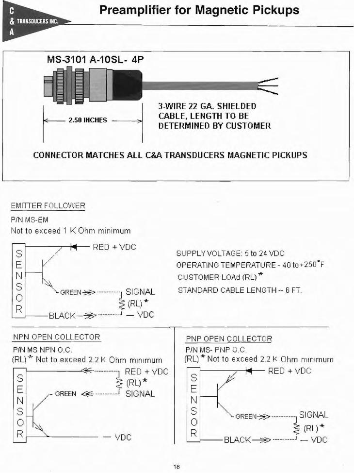
Preamplifier for Magnetic Pickups
MS-3101 A-10SL- 4P
r- 2.50 INCHES
3-WIRE 22 GA. SHIELDEDCABLE, LENGTH TO BEDETERMINED BY CUSTOMER
CONNECTOR MATCHES ALL C&A TRANSDUCERS MAGNETIC PICKUPS
EMITIER FOLLOVVER
PiN MS-EM
r\Jot to exceed 1 K Ohm minimum
.......-.
1----."........-+..._- RED + Vo Cr o• -_./...
,=:;t
/
s --~""- GREEtlJ~"'-> ----------] SIGNAL
o :2.: (RU *R c;:: }L-J--- BLAC K-~> J - VO C
~,IF'N OPEr\j COLLECTOR
PiN MS NPr'~ O.C.(RL) ~- Not to exceed 2.2 K Ohm mlnlmurn
I---------<::;~----------] RED + VO CS
~ (RL) *E _GREEN <..::- J SIGNALt\JSo ~Rf-----'~---- - VoC
SUPPLY VOLTAGE: 5 to 24 VDC
OPERATING TEMPER.ATURE - 40 to +250·F
CUSTOMER LOAd (Rl) "*
STAt\1 D.A.R 0 CAB LE LE NGTH -- Ei FT.
PNP OPEN COLLECTOR
PiN MS- PNP O.C.(RL) *" Not to exceed 2.2 K Ohm minimum
I----..,....--j..-- RED + VoCSENS '''"~ '-GREEN~--------t:~~~L
L-J--- BLACK~ J - VOC
18

Hall-Effect Proximity Sensors
518-18 UNf 2-A 3-\Mre cable,
S __ _ /22 A'WO.16" Min ~c::::=J 71r-----------,~
2.00"---1PIN H.E. 200-34SPECFICATIONS
5 TO 24 VOC SlPPLY VOLTAGELOAD CURRENT _ow. 20 Ma MaxREPEATABLITY:------------- 010·LEADS S1ZE:--- 22 AlNO. STRA/IDEORESPONSE:-- 1 TO 10.000 PULSESJSECONDL.ED. ------------ OPTIONALOLJrNATER------------- RESISTANTSHOCK AND veRAnoN------- RESISTANTTBIF .RANGE:--------------- 040 TO 250 FSensor p pe: ....N.O. NPN (Sinking)Gap Distance:------------O to 0.100"South side of Magnet turns Switch 01\1
19
FEATLRE AN> BENE FITS:
COMPATI3LE lMTH DIOITAL LOGICREVERSE Battery PROTECTIONNEEDS ONLY AN UNREOULATED SLPPLYSOUD STATE RElJABLJTYOPEN COlLECTOR 25 mao OUTPUTRESISTANT TO PHYSICAL STRESS

Hall-Effect Bi-Polar Ring Gear Sensors
518-1 B l..N" 2-A 3-\o\4re cable I
N S~_22A"""~'htn ~c::::::J~ 71-1 ~
l~ 200' --1 LED
PIN H.E. 200-81SPECfICAOON$
5 TO 24 YDC SLPPl.Y VOlTAGELOAD CURRENT --' 20 Ma MaxREPfATABUTY:---- 010"LEADS S1ZE:---- 22 AWO. STRA/'ODRESPONSE:--1 TO 10.00:1 PULSESISECQIII).L.ED. ---- OPTIONALOLJtIIIATER . _._----.- RESISTANTSHOCK AND VIElRAllON------ RESISTANTTEhF.RANOE;._---------- 040 TO 250 FSensor Type: ....N. O. NPN (Sinking)Gap D~stance:--------o to 0.100·South side of Magnet turns Switch ONNorth side of Magnet turns Switch OFF
20
FEATLRf AN> BENE FITS:
COMPATELElMTH DIGITAl. LOGICREVERSE Battery PROTECTIONNEEDS OI'LY AN utftOOLATED SLPPLYSOLID STATE RELJ.A.BLJTYOPEN COLLECTOR 251M. OUTPUTRESISTANT TO PHYSICAL STRESS
S+Vdc
-~E powersupplyNS ElIelck -===- Ond. 20 rnA Mele.
0R SlQnal Green

Hall-Effect Zero Speed Sensors
18" Mil.) condo 22 A
PM HE-I25218-2.2K
RED + VDC
2.2KOHMS
g~ ~4tRt.
ElLACK-VDC 4-l
SlJPPLY VOLTAGE: 5.- 25 VDCrm 20 MIl. Max.TEMP- RANGE::-40to 2fil FOUTPUT SIGNAL:LCW -400 MY.MAX.@ 20 mAo SN<HIGH- RlJ( 5Y.
RL+2.2 K
5.e-1 a.LN"-2A
SUPPLY VOLTAGE: 5,- 2'5 voe@l20 Me. Max.TEMP- ~ANGE::-40to 257 fOUTPUT SIGNAL:LCW-400 MY),tIAX.@2O mAo SN<J-IQH- RLX 5Y.
RL+4.7 K
•REO+VDC
4jRt.
'-::-------<.4-1ElLACK-VDC
.l4.7 KOI-HS
QREENOUTPUT
PMIE.Q52W- 4.1K
1B" MIn.3 condo 22 Aw
OrlerilJllon F1eIIs
5J8..18-1.N=-2A1fr' Min.) condo 22 A
PM HE-I252t1... 1K
RED + VDC
1 K 0I-tl4S
~_~:;.:..RE=EEN~--«..~
Rt.'-::-------<.4-1
BLACK-VOC
SlPPLY VOL.TAOf: 5.- 25 VDCG! 20 Mo. Max.TEMP- RANGE::-40to 257 F0UiPUT SIGNAL:LCW =400 MY.MAX.@ 20 mAo SN<HIOH- RLX 5V.
RL+1 K
21