ci rd straumann® purebase basic information
TRANSCRIPT

Technical Information
CI RD Straumann® PUREbase
Basic Information

This guide has been created for dental technicians and dentists working with the CI RD Straumann® PUREbase, designing screw-retained or cement-retained customized prosthetic reconstructions, such as copings, crowns or overdentures. It provides additional step-by-step information on working with the CI RD Straumann® PUREbase. Failure to follow the proce-dures outlined in these instructions may harm the patient and/or lead to any or all of the following complications: aspiration or swallowing of a component, breakage, infection.
Note: Implant-borne superstructures require optimal oral hygiene on the patient’s part. This must be considered by all parties involved when planning and designing the restoration. Not all detailed information can be found in this guide. Reference to available Straumann procedure manuals will be made throughout this document.

1
Contents
1 CI RD Straumann® PUREbase 2
2 System Overview 32.1 CI RD Straumann® PUREbase Implant Kit 3
2.2 Design 3
2.3 Digital Workflow (CADCAM) 4
3 Lab procedure for CI RD Straumann® PUREbase 53.1 Preparation 5
3.2 Open-tray Impression 5
3.3 Fabricating the master cast (with Sleeve and CI RD Repositionable Implant Analog) 6
3.4 Digital workflow 6
3.5 Bonding 7
3.6 Insertion (dental practice) 12
4 Product reference list 134.1 CI RD Straumann® PUREbase 13
4.2 Auxilliaries 13
2
1 CI RD Straumann® PUREbase
The CI RD Straumann® PUREbase is a titanium base placed onto the Straumann® PURE Ceramic Implant to provide support for customized prosthetic restorations. It is indicated for screw-retained single tooth restorations, cement-retained single tooth restorations and cement-retained bridge restorations. All digitally designed copings and/or crowns for use with theStraumann PUREbase system are intended to be sent to Straumann for manufacture at a validated milling center. The CI RD Straumann® PUREbase is available in two abutment heights, 3.5 mm and 5.5 mm.
The CI RD Straumann® PUREbase is supplied with a Basal Screw and a Bonding Aid. The Basal Screw is intended for fixing the abutment to the dental implant, while the Bonding Aid is indicated for the correct alignment between the CI RD Straumann® PUREbase and the coping/crown at implant shoulder level.
No time to read?Watch the movie on the CI RD Straumann® PUREbase lab procedure.
3
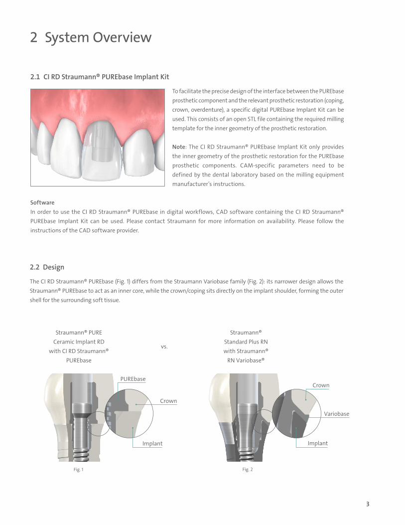
2.2 Design
The CI RD Straumann® PUREbase (Fig. 1) differs from the Straumann Variobase family (Fig. 2): its narrower design allows the Straumann® PUREbase to act as an inner core, while the crown/coping sits directly on the implant shoulder, forming the outer shell for the surrounding soft tissue.
2 System Overview
Fig. 1 Fig. 2
Straumann® PURE Ceramic Implant RD
with CI RD Straumann® PUREbase
vs.
Straumann® Standard Plus RN with Straumann®
RN Variobase®
PUREbase
Crown
Crown
Variobase
ImplantImplant
2.1 CI RD Straumann® PUREbase Implant Kit
To facilitate the precise design of the interface between the PUREbase prosthetic component and the relevant prosthetic restoration (coping, crown, overdenture), a specific digital PUREbase Implant Kit can be used. This consists of an open STL file containing the required milling template for the inner geometry of the prosthetic restoration.
Note: The CI RD Straumann® PUREbase Implant Kit only provides the inner geometry of the prosthetic restoration for the PUREbase prosthetic components. CAM-specific parameters need to be defined by the dental laboratory based on the milling equipment manufacturer’s instructions.
SoftwareIn order to use the CI RD Straumann® PUREbase in digital workflows, CAD software containing the CI RD Straumann® PUREbase Implant Kit can be used. Please contact Straumann for more information on availability. Please follow the instructions of the CAD software provider.
4
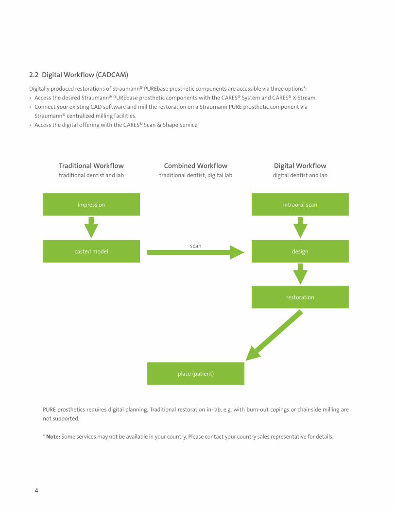
2.2 Digital Workflow (CADCAM)
Digitally produced restorations of Straumann® PUREbase prosthetic components are accessible via three options*: ѹ Access the desired Straumann® PUREbase prosthetic components with the CARES® System and CARES® X-Stream. ѹ Connect your existing CAD software and mill the restoration on a Straumann PURE prosthetic component via
Straumann® centralized milling facilities. ѹ Access the digital offering with the CARES® Scan & Shape Service.
PURE prosthetics requires digital planning. Traditional restoration in-lab, e.g. with burn-out copings or chair-side milling are not supported.
* Note: Some services may not be available in your country. Please contact your country sales representative for details.
impression intraoral scan
restoration
casted model
place (patient)
design
Traditional Workflowtraditional dentist and lab
Combined Workflowtraditional dentist; digital lab
scan
Digital Workflowdigital dentist and lab
5
3 Lab procedure for CI RD Straumann® PUREbase
3.1 Preparation
PrerequisitesThe tooth shade has been identified and noted (using color chart or digital measuring device). Both shade information and impression have been sent to the dental lab.
3.2 Open-tray Impression
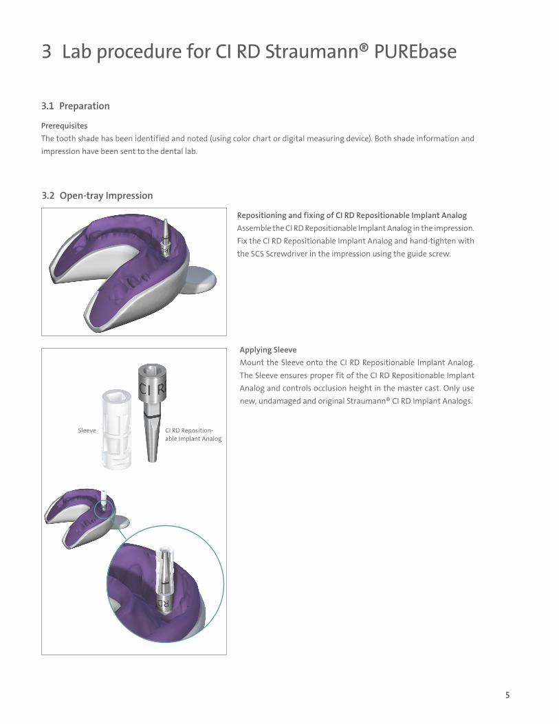
Repositioning and fixing of CI RD Repositionable Implant AnalogAssemble the CI RD Repositionable Implant Analog in the impression.Fix the CI RD Repositionable Implant Analog and hand-tighten with the SCS Screwdriver in the impression using the guide screw.
Applying SleeveMount the Sleeve onto the CI RD Repositionable Implant Analog. The Sleeve ensures proper fit of the CI RD Repositionable Implant Analog and controls occlusion height in the master cast. Only use new, undamaged and original Straumann® CI RD Implant Analogs.
Sleeve CI RD Reposition-able Implant Analog
6
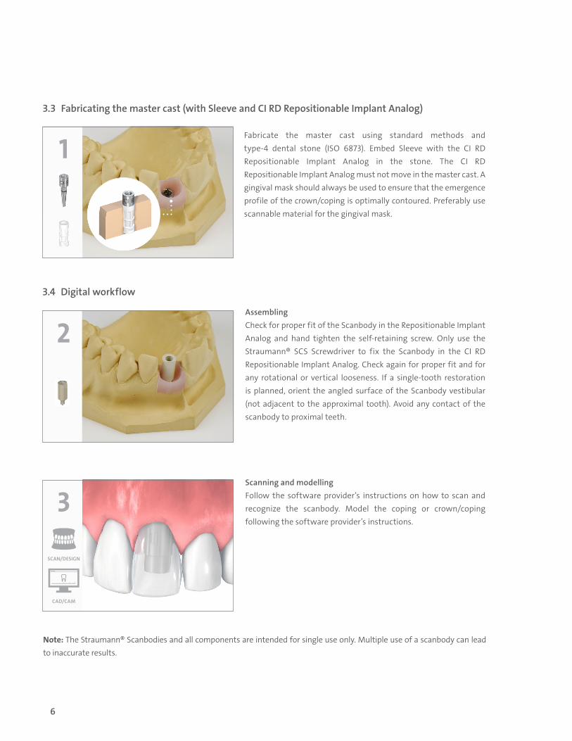
3.3 Fabricating the master cast (with Sleeve and CI RD Repositionable Implant Analog)
AssemblingCheck for proper fit of the Scanbody in the Repositionable Implant Analog and hand tighten the self-retaining screw. Only use the Straumann® SCS Screwdriver to fix the Scanbody in the CI RD Repositionable Implant Analog. Check again for proper fit and for any rotational or vertical looseness. If a single-tooth restoration is planned, orient the angled surface of the Scanbody vestibular (not adjacent to the approximal tooth). Avoid any contact of the scanbody to proximal teeth.
Scanning and modellingFollow the software provider’s instructions on how to scan and recognize the scanbody. Model the coping or crown/coping following the software provider’s instructions.
3.4 Digital workflow
1Fabricate the master cast using standard methods and type-4 dental stone (ISO 6873). Embed Sleeve with the CI RD Repositionable Implant Analog in the stone. The CI RD Repositionable Implant Analog must not move in the master cast. A gingival mask should always be used to ensure that the emergence profile of the crown/coping is optimally contoured. Preferably use scannable material for the gingival mask.
2
CAD/CAM
SCAN/DESIGN
3
Note: The Straumann® Scanbodies and all components are intended for single use only. Multiple use of a scanbody can lead to inaccurate results.

7
4
Remove CI RD Repositionable Implant Analog.
Insert the Bonding Aid (included in every Straumann® PUREbase package).
Shorten Bonding Aid when it sticks out at bottom of the master cast.
3.5 Bonding
Remove the gingival mask.
5
6
7

8
11
9
8Fix the Straumann® PUREbase abutment to the Bonding Aid with the respective screw and hand-tighten with the SCS Screwdriver.
Note: CI RD Straumann® PUREbase and its components are non-sterile when delivered. Before placing the restoration in the patient's mouth, the product must be cleaned, disinfected or sterilized.It is not necessary to sandblast the PUREbase to obtain a strong bond.
Due to the symmetrical nature of the four cams, confirm the position of the crown/coping according to the actual patient anatomy prior to bonding.
Note: To ensure precise seating of the prosthetic restoration on the PUREbase, always bond on the master cast. Make sure the PUREbase is seated firmly on the bonding aid as the crown/coping has a direct contact surface to the implant shoulder.
Seal the screw channel with e.g. wax.
If specified in the adhesive/cement manufacturer's processing instructions, apply appropriate primer agents to the PUREbase and restoration.
10

9
Apply a layer of self-adhesive cement to the inner surface of the crown/coping.
Note: Only suitable self-adhesive cementation systems for the respective material shall be used. Follow the manufacturer's instructions for use for both the dental material and cement/bonding material.
Apply a layer of self-adhesive dental cement onto the upper third of the PUREbase. Use a clean brush to distribute cement over the entire bonding surface of the PUREbase.
Press the crown/coping down to the PUREbase/Bonding Aid.
Immediately remove excess cement from the screw channel (e.g. with a clean brush).
12
13
14
15

10
Ensure with a right/left movement that there is no cement between the Bonding Aid and the crown/coping.
Press the crown/coping down for at least two minutes to avoid the push-back effect of the cement which creates a microgap in the final restoration.
Follow the cement manufacturer’s instructions for hardening. Keep pressing down during hardening with UV light.
16
2 MIN
PUSH
17
PUSH
18

11
Unscrew the basal screw. Cement rediduals remain on bonding aid.
Remove excessive cement using a sharp instrument. Do not use a rotating instrument.
Important: Check the resultReposition the Repositionable Implant Analog onto the master cast and position the restoration. Check tight fit of restoration in master model or analog. If a gap is identified, repeat the procedure until the gap between implant and crown/coping has been eliminated.
Note: Remaining cement can lead to a microgap and untight fit of the final restoration.Do not fire the abutment after bonding.
19
20
21

12
3.6 Insertion (dental practice)
Fix the final restoration on the master cast before delivery to the dentist. Check tight fit of restoration in master model or analog. Deliver only when there is no visible microgap between restoration and implant analog.
Step 1 – Preparation ѹ Remove the healing cap or temporary restoration. ѹ Remove the restoration from the master cast and unscrew the PUREbase prosthetic components from the CI RD Reposi-
tionable Implant Analog. ѹ Thoroughly clean and dry the interior of the implant and the abutment.
Note: Always ensure that surfaces of threads and screw heads are clean and that a new screw is used for the final restoration.
Step 2 – Final insertion
Option A: Screw-retained final restorationPosition the sterilized PUREbase prosthetic restoration in the implant. Tighten the screw to 35 Ncm using the SCS Screwdriver together with the Ratchet and the Torque Control Device.Close the SCS screw channel with cotton and sealing compound (i.e. gutta-percha). This allows for subsequent removal of the PUREbase in case a crown/coping or overdenture replacement should be required.
Option B: Cement-retained final restorationPosition the sterilized PUREbase in the implant. Tighten the screw to 35 Ncm using the SCS Screwdriver together with the Ratchet and the Torque Control Device.Close the screw channel with cotton and sealing compound (e.g. gutta-percha). This allows for subsequent removal of the PUREbase in case a crown/coping replacement should be required.Cement the superstructure to the abutment.Remove excess cement.Check the horizontal implant-abutment connection for possible gaps.
13
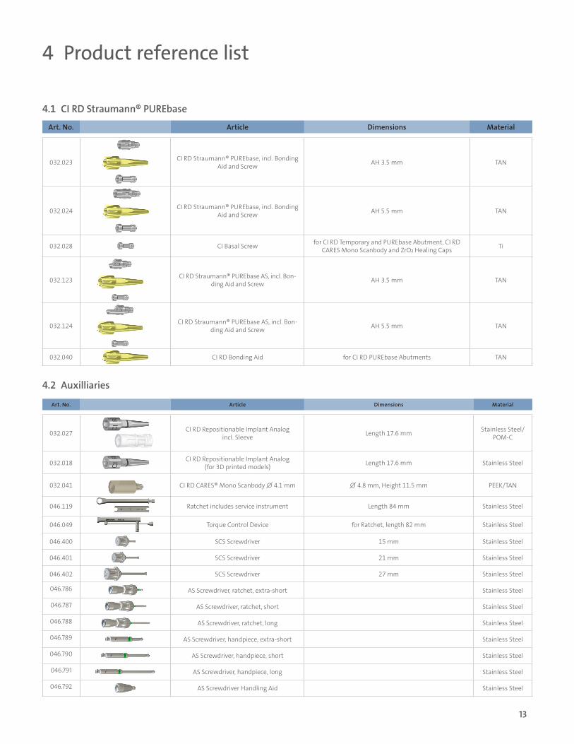
4 Product reference list
4.1 CI RD Straumann® PUREbase
Art. No. Article Dimensions Material
032.023 CI RD Straumann® PUREbase, incl. Bonding Aid and Screw AH 3.5 mm TAN
032.024 CI RD Straumann® PUREbase, incl. Bonding Aid and Screw AH 5.5 mm TAN
032.028 CI Basal Screw for CI RD Temporary and PUREbase Abutment, CI RD CARES Mono Scanbody and ZrO₂ Healing Caps Ti
032.123 CI RD Straumann® PUREbase AS, incl. Bon-ding Aid and Screw AH 3.5 mm TAN
032.124 CI RD Straumann® PUREbase AS, incl. Bon-ding Aid and Screw AH 5.5 mm TAN
032.040 CI RD Bonding Aid for CI RD PUREbase Abutments TAN
Art. No. Article Dimensions Material
032.027 CI RD Repositionable Implant Analog incl. Sleeve Length 17.6 mm Stainless Steel/
POM-C
032.018 CI RD Repositionable Implant Analog (for 3D printed models) Length 17.6 mm Stainless Steel
032.041 CI RD CARES® Mono Scanbody ∅ 4.1 mm ∅ 4.8 mm, Height 11.5 mm PEEK/TAN
046.119 Ratchet includes service instrument Length 84 mm Stainless Steel
046.049 Torque Control Device for Ratchet, length 82 mm Stainless Steel
046.400 SCS Screwdriver 15 mm Stainless Steel
046.401 SCS Screwdriver 21 mm Stainless Steel
046.402 SCS Screwdriver 27 mm Stainless Steel
046.786 AS Screwdriver, ratchet, extra-short Stainless Steel
046.787 AS Screwdriver, ratchet, short Stainless Steel
046.788 AS Screwdriver, ratchet, long Stainless Steel
046.789 AS Screwdriver, handpiece, extra-short Stainless Steel
046.790 AS Screwdriver, handpiece, short Stainless Steel
046.791 AS Screwdriver, handpiece, long Stainless Steel
046.792 AS Screwdriver Handling Aid Stainless Steel
4.2 Auxilliaries

USL
IT.11
95
5/1
9
V1 P
MR
Straumann North American Headquarters Straumann USA, LLC 60 Minuteman Road Andover, MA 01810 Phone 800/448 8168 (US) 800/363 4024 (CA) Fax 978/747 2490 www.straumann.us www.straumann.ca
© Straumann USA, LLC 2019. All rights reserved. Straumann® and/or other trademarks and logos from Straumann® that are mentioned herein are the trademarks or registered trademarks of Straumann Holding AG and/or its affiliates. All rights reserved.
ifu.straumann.com