straumann® pro arch with straumann® blx implant system ...€¦ · straumann® pro arch with...
TRANSCRIPT

Technical Information
Straumann® Pro Arch with Straumann® BLX Implant System
Basic Information


Contents
1. Treatment procedure 2
1.1 Implant planning 2
1.2 Surgical procedure 3
1.3 Prosthetic treatment 7
2. Product overview 13
Appendix A: Straumann® Pro Arch Guide 16
Appendix B: Straumann® Bone Level Bone Profiler 17
Appendix C: Quick Guide for Holding Key for Straumann® Screw-retained Abutments 21
1
1. Treatment procedure
1.1 Implant planning
1.1.1 Planning phaseFor optimal and long-lasting results, a prosthetic-driven planning phase is essential, and it should be executed in collaboration with all partners involved.During the planning phase the following aspects need to be considered:
▪ Clarify patient’s expectations ▪ Analyze patient’s oral hygiene compliance ▪ Patient history (bone density, bone volume, sufficient lip support) ▪ Decide on final prosthetic restoration (fixed / removable) ▪ Decide on surgical procedure and implant placement based on bone volume (number of implants, im-
plant angulation if necessary) ▪ Consider long-term post-operative care and maintenance
Proper diagnosis and treatment planning, including the consideration of your patient’s chief complaints as well as an evidence-based implant / prosthetic design, will result in a successful treatment. These factors can significantly improve the patient’s quality of life1.
Planning and implant preparation for the full-arch restoration can either be done via conventional methods or with the help of digital planning softwares (e. g. coDiagnostiX®). In this treatment guide, the focus will be on the conventional procedure with an open-flap approach.
For additional information on Straumann® Guided Surgery, please consult the manual Basic Information on Straumann® Guided Surgery (NAMLIT 1006).
For additional information on Straumann® coDiagnostiX®, please contact your local Straumann® Territory Manager.
2

1.2 Surgical procedure
1.2.1 Surgical preparation and general considerationsBased on the treatment decision and the desired final restoration, define the following:
A
P
2
1a
1b
1. Position and orientation of the implant based on bone volume (according to Dr. Paulo Malo, MALO CLINIC®): ▪ full bone volume up to molars: straight implant placement (1a) ▪ bone volume sufficient in anterior region up to premolars:
tilted implant placement in the posterior region (1b)
2. Implant position considering Anterior-Posterior (AP) spread for biomechanical stability.
3. Implant angulation (max. angulation): 45° (= higher A/P spread for higher stability).
4. For a restoration based on abutment level, choose an abut-ment-level impression, also recommended when implants are tilted.For a final restoration using Straumann® CARES®, use an abut-ment-level impression to ensure optimal results.
5. Together with the dental lab, produce an individual acrylic guide to verify implant axis, abutment / coping position and screw channels throughout the overall procedure.
3
1.2.2 Surgical procedure (flap procedure), abutment placement and immediate temporizationMake sure the surgical and prosthetic planning are both completed and critical anatomical sites are not harmed (maxilla: sinus / mandible: mandibular nerve). In some cases, the individual patient situation may require tilting of the implants. Posterior-tilted implants provide additional distal support for the prosthesis2.
Prerequisites: ▪ Remaining dentition removed ▪ Flap opened and ready for implant placement ▪ Acrylic guide prepared by dental lab
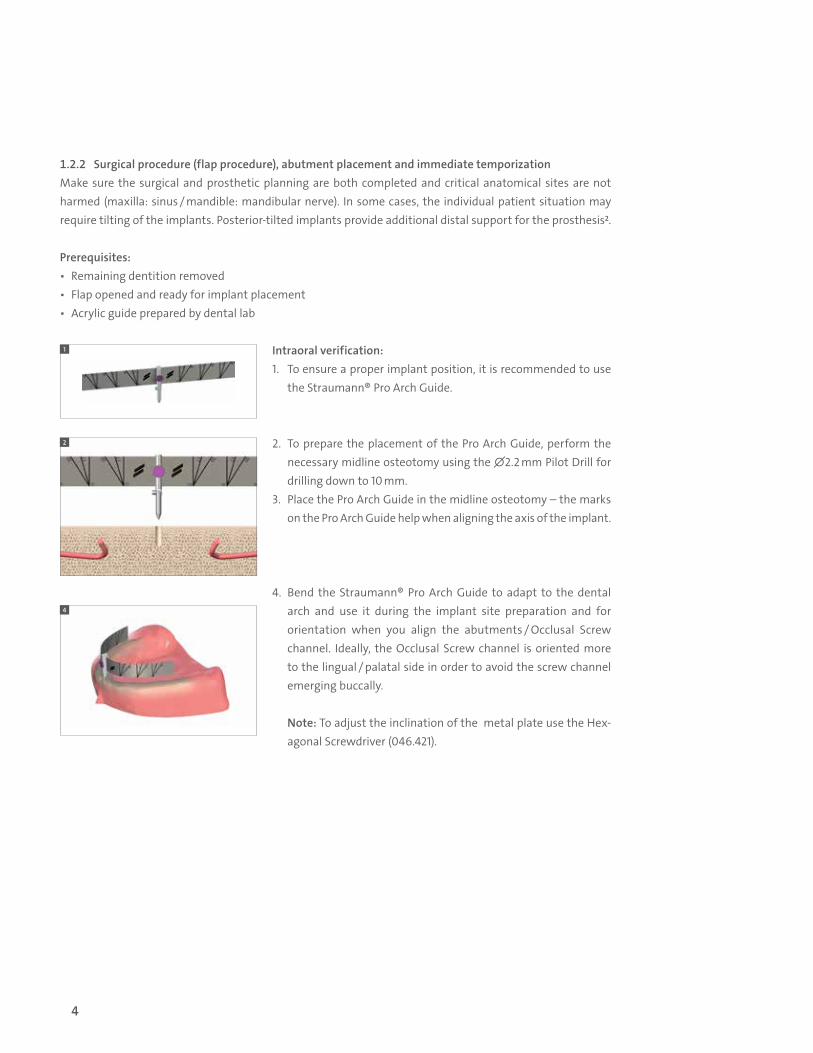
Intraoral verification: 1. To ensure a proper implant position, it is recommended to use
the Straumann® Pro Arch Guide.
2. To prepare the placement of the Pro Arch Guide, perform the necessary midline osteotomy using the ∅2.2 mm Pilot Drill for drilling down to 10 mm.
3. Place the Pro Arch Guide in the midline osteotomy – the marks on the Pro Arch Guide help when aligning the axis of the implant.
4. Bend the Straumann® Pro Arch Guide to adapt to the dental arch and use it during the implant site preparation and for orientation when you align the abutments / Occlusal Screw channel. Ideally, the Occlusal Screw channel is oriented more to the lingual / palatal side in order to avoid the screw channel emerging buccally.
Note: To adjust the inclination of the metal plate use the Hex-agonal Screwdriver (046.421).
1
2
4
4

Implant site preparation: 5. Drill to the appropriate depth and check correct angulation using
the marks on the Straumann® Pro Arch Guide.
6. Place the appropriate implant following the Straumann® BLX Implant System surgical protocol.
7. Use the Straumann® Bone Level Bone Profiler to prepare the bone coronally to the implant shoulder in cases where the bone interferes with the abutment’s emergence profile. For more de-tails see Appendix B: Straumann® Bone Level Bone Profiler.
8. Position the final abutments with a torque of 35 Ncm. The Transfer and Alignment Pin is delivered pre-assembled with the angled abutment and simplifies abutment placement in the posterior region. Furthermore, the Transfer and Alignment Pin indicates orientation of the occlusal screw channel.
9. For anterior implant placement repeat steps 5 to 7. Note: For torquing the abutment correctly despite low primary stability, refer to the Quick Guide Holding Key for Straumann® Screw-retained Abutments on page 21.
5
6
7
8
5

10
If no immediate temporization is desired, place Protective Caps for Straumann® Screw-retained Abutments directly onto the abutments and hand-tighten them.
Do not keep the Protective Caps in the patient’s mouth for more than 30 days. Provide sufficient space in the patient’s temporary denture until the final prosthesis is placed.
10. Place the titanium copings on top of the abutments and verify orientation and position with the help of the acrylic guide. Use the acrylic guide throughout the procedure to verify implant position and orientation.
6

11. Place non-engaging Titanium Copings on the anterior and pos-terior abutments.
12. Ensure correct position of the Titanium Copings on the abut-ments. Avoid any gaps between the Titanium Coping and the abutment.
13. Use the acrylic guide to check the alignment and position of the Titanium Copings. Once the position is ensured make sure the occlusal set up fits with the prepared prosthesis.Use impression material to fix the Titanium Copings to the acrylic guide.
14. Use the acrylic guide to transfer the clinical situation to the dental lab.
15. The dental lab adapts the temporary restoration based on all information provided. Make sure to prepare sufficient space in the temporary restoration to fit in the Titanium Copings.
11
13
14
1.3 Prosthetic treatment
1.3.1 Immediate temporization with the help of the dental lab Prerequisites: ▪ Acrylic guide based on patient situation prepared by the dental lab ▪ Temporary restoration prepared by dental lab ▪ Abutments placed and tightened to 35 Ncm
7

Open-tray impression 1. Place the Impression Post accurately into the abutment and
hand-tighten the Guide Screw.Note: For multi-unit restorations use the impression compo-nents with non-engaging features.
2. Ensure correct positioning of the Impression Posts to ensure proper fit of the restoration.
3. Make perforations in the custom-made impression tray (light-cured resin) according to the individual situation so that the Po-sitioning Screw of the Impression Post sticks out visibly.
1
1.3.2 Impression taking on abutment level for final restoration Prerequisites: ▪ Implants, abutments and Protective Cap placed ▪ Implant site healed ▪ Temporary prosthesis is removed
16
17
16. Intraorally, fix the Titanium Copings with the existing reworked prosthesis using resin material.
17. Finalize and polish the temporary restoration in the dental lab.18. Place the temporary restoration in the patient’s mouth and tighten
the Occlusal Screws to 15 Ncm using the SCS Screwdriver along with the Ratchet and the Torque Control Device.
8
Option for closed-tray impression:Place the Impression Posts onto the Screw-retained Abutments, ensure correct positioning with the retentive features and click the Positioning Caps onto the Impression Posts allowing a vestibular orientation. After taking the impression, forward all impression components to the dental lab for processing. In the dental lab, screw the Impression Posts onto the corresponding analogs and click back into the Positioning Caps.
Note: All Impression Posts are intended for single use only to ensure optimal fit and precise impression taking for each patient. Hydrocolloid is not suitable for this application due to its low tensile strength.
4
5
9
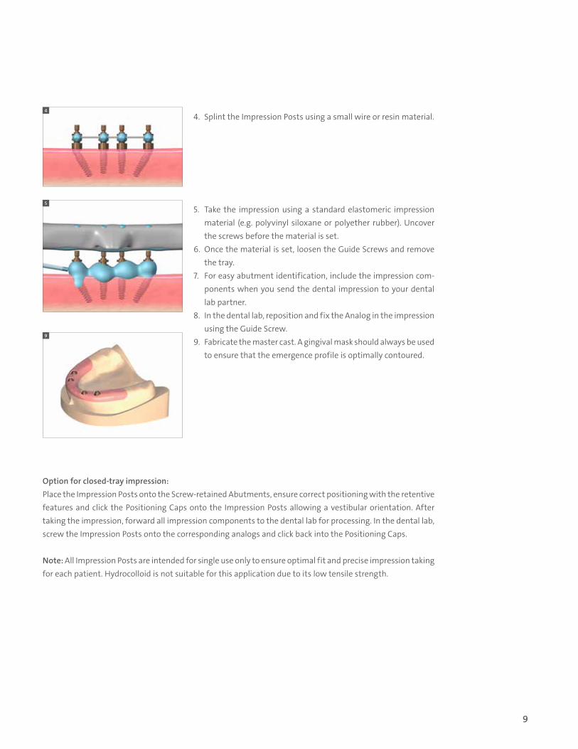
4. Splint the Impression Posts using a small wire or resin material.
5. Take the impression using a standard elastomeric impression material (e.g. polyvinyl siloxane or polyether rubber). Uncover the screws before the material is set.
6. Once the material is set, loosen the Guide Screws and remove the tray.
7. For easy abutment identification, include the impression com-ponents when you send the dental impression to your dental lab partner.
8. In the dental lab, reposition and fix the Analog in the impression using the Guide Screw.
9. Fabricate the master cast. A gingival mask should always be used to ensure that the emergence profile is optimally contoured.
9
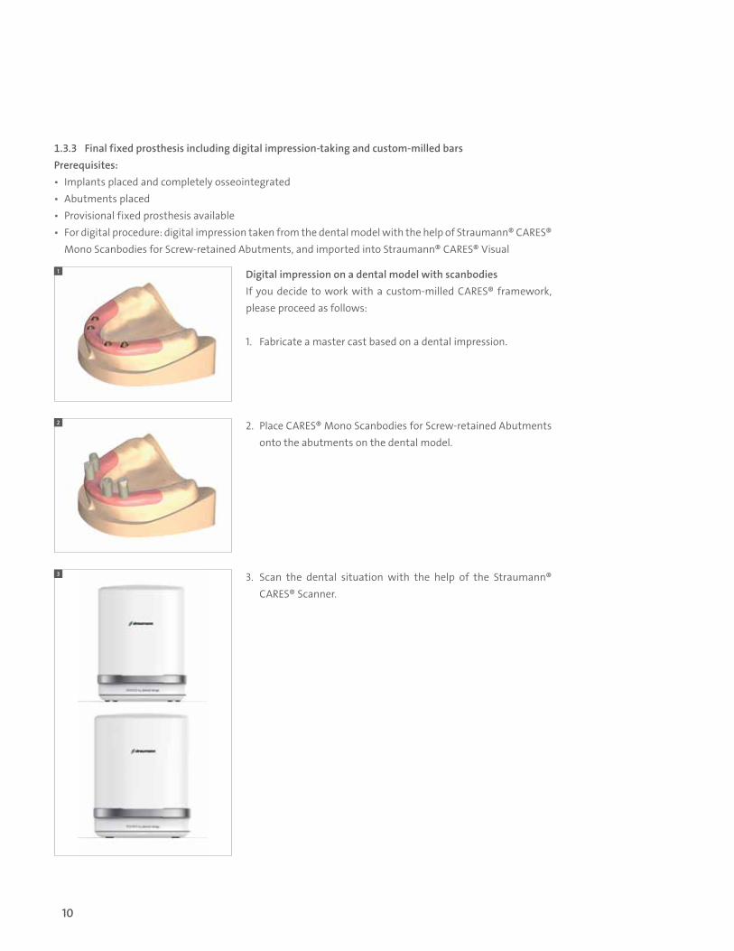
Digital impression on a dental model with scanbodiesIf you decide to work with a custom-milled CARES® framework, please proceed as follows:
1. Fabricate a master cast based on a dental impression.
2. Place CARES® Mono Scanbodies for Screw-retained Abutments onto the abutments on the dental model.
3. Scan the dental situation with the help of the Straumann® CARES® Scanner.
1
2
3
1.3.3 Final fixed prosthesis including digital impression-taking and custom-milled barsPrerequisites: ▪ Implants placed and completely osseointegrated ▪ Abutments placed ▪ Provisional fixed prosthesis available ▪ For digital procedure: digital impression taken from the dental model with the help of Straumann® CARES®
Mono Scanbodies for Screw-retained Abutments, and imported into Straumann® CARES® Visual
10
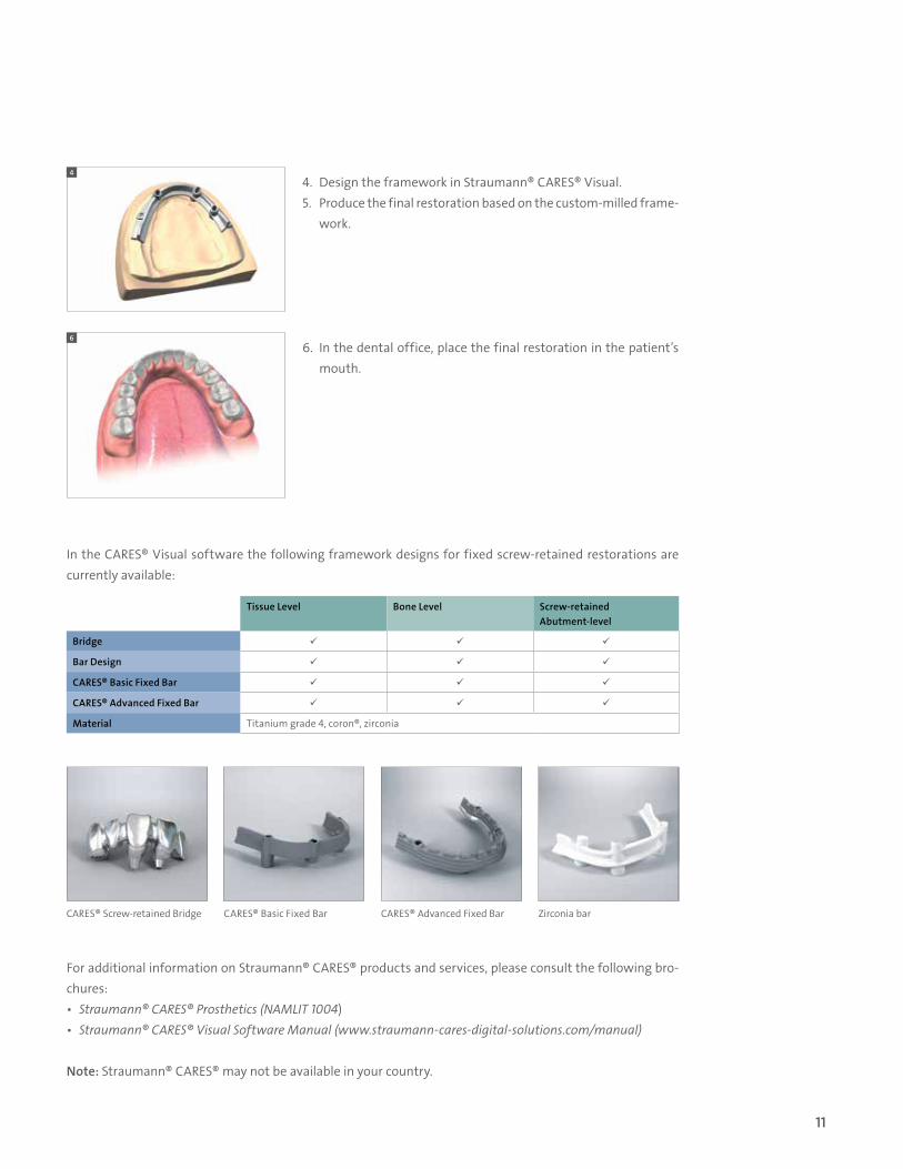
In the CARES® Visual software the following framework designs for fixed screw- retained restorations are currently available:
Tissue Level Bone Level Screw-retained Abutment-level
Bridge
Bar Design
CARES® Basic Fixed Bar
CARES® Advanced Fixed Bar
Material Titanium grade 4, coron®, zirconia
CARES® Basic Fixed Bar CARES® Advanced Fixed Bar Zirconia barCARES® Screw-retained Bridge
For additional information on Straumann® CARES® products and services, please consult the following bro-chures: ▪ Straumann® CARES® Prosthetics (NAMLIT 1004) ▪ Straumann® CARES® Visual Software Manual (www.straumann-cares-digital-solutions.com/manual)
Note: Straumann® CARES® may not be available in your country.
4
6
4. Design the framework in Straumann® CARES® Visual. 5. Produce the final restoration based on the custom-milled frame-
work.
6. In the dental office, place the final restoration in the patient’s mouth.
11

1.3.4 Straumann® CARES® Scan & Shape option If you do not have access to a scanner and software you have the option to use our CARES® Scan & Shape service*:
7. Fabricate a master cast based on a dental impression.
8. Send the impression and order sheet to your local CARES® Scan & Shape supplier and follow their instructions.
9. Produce the final restoration based on the custom-milled framework.
10. In the dental office, place the final restoration in the patient’s mouth.
For more detailed information please refer to your local subsidiary.
7
8
1.3.5 Care and maintenanceFor long-term success and proper fit of the fixed prosthesis, thorough patient instruction and periodic check-ups (at least once a year) are recommended.
Careful maintenance of the fixed restoration provided it is not necessary to exchange the Occlusal Screws at each check-up visit.
During these visits, you should carefully examine the: ▪ Condition of peri-implant tissues with regard to diseases2:
‒ Plaque and calculus, bleeding, recession, bone loss, radiographs ▪ Superstructure:
‒ Occlusal fit and articulation, proper fit of the fixed prosthesis, wear of occlusal surface, retention, at-tachment loosening, abutment status
▪ Function of the prosthesis.
For proper care at home, instruct the patient to clean the space between gingiva and fixed prosthesis, es-pecially around the implants on a regular basis. Dental floss, bushy dental floss or interdental brushes are recommended.
* Currently only available in the US.
12

2. Product overview
Art. No. Image Product Description Material
Screw-retained Abutments 0°, sterile
062.4722S
RB/WB Screw-retained Abutment
straight, angle 0°, ∅4.6 mm, gingiva height 1.5 mm, sterile
TAN
062.4723S straight, angle 0°, ∅4.6 mm, gingiva height 2.5 mm, sterile
062.4724S straight, angle 0°, ∅4.6 mm, gingiva height 3.5 mm, sterile
062.4725S straight, angle 0°, ∅4.6 mm, gingiva height 4.5 mm, sterile
Screw-retained Abutments 17°, sterile
062.4733S
RB/WB Screw-retained Abutment
angled, angle 17°, ∅4.6 mm, gingiva height 3.5 mm, sterile
TAN062.4734S angled, angle 17°, ∅4.6 mm, gingiva height 4.5 mm, sterile
062.4735S angled, angle 17°, ∅4.6 mm, gingiva height 5.5 mm, sterile
Screw-retained Abutments 30°, sterile
062.4743S
RB/WB Screw-retained Abutment
angled, angle 30°, ∅4.6 mm, gingiva height 3.5 mm, sterile
TAN062.4744S angled, angle 30°, ∅4.6 mm, gingiva height 4.5 mm, sterile
062.4745S angled, angle 30°, ∅4.6 mm, gingiva height 5.5 mm, sterile
Replacement Screws
065.0036 RB/WB Basal Screw*
for RB/WB Temporary Abutments, Anatomic Abutments, Variobase® for Crown, Variobase® for Bridge/Bar Cylindrical, angled Screw-retained Abutments, and angled Novaloc® Abutments, length 6.1 mm TAN
023.4763 NC/RC Occlusal Screwfor NC/RC Titanium, Gold, Burn-Out and Variobase® Coping for Screw-retained Abutments, length 3.7 mm
*Currently only available in the US
13

Impression Posts (at abutment level) for Multi-Unit Restorations (non-engaging)
025.0012Impression Posts for Open-tray Impression
for Screw-retained Abutments, abutment level, ∅4.6 mm
TAN
025.0014Impression Posts for Closed-tray Impression
TAN/POM
Digital Impression
025.0001 CARES® Mono Scanbodyfor Screw-retained Abutments, abutment level, including Fixation Screw, ∅4.6 mm
PEEK
025.0008 Repositionable Analog for Screw-retained Abutments, ∅4.6 mmStainless steel
Analogs
023.4756
Analog for Screw-retained Abutments ∅4.6 mm
for Screw-retained Abutments ∅4.6 mm, straight
TAN025.0050 for Screw-retained Abutments ∅4.6 mm, edentulous, straight
023.4757for Screw-retained Abutments ∅4.6 mm, angled, angle 17°/30°
Lab Auxiliaries
025.0005 Polishing Aidfor Screw-retained Abutments ∅4.6 mm, packaging 4 pieces TAN
025.0005V4
025.0006 Lab Processing Screw for Screw-retained Abutments, length 20 mm Stainless steel
025.0052 for Screw-retained Abutments, length 10 mm
Protective Caps
024.4323-04
Protective Cap ∅4.6 mm
for Screw-retained Abutments ∅4.6 mm, including screw 023.4763, height 5.1 mm, packaging 4 pieces
PEEK024.4324-04for Screw-retained Abutments ∅4.6 mm, including screw 023.4763, height 6.6 mm, packaging 4 pieces
024.4325-04for Screw-retained Abutments ∅4.6 mm, including screw 023.4763, height 8.1 mm, packaging 4 pieces
Auxiliary Parts
026.0016Straumann® Planning Guide
visual guide for tilted implant placement in Straumann® Pro Arch cases
TAV/Ti
025.0009Transfer and Alignment Pin
for Screw-retained Abutments TAN
025.0019 Holding key for Screw-retained Abutments (angled only)Stainless steel
Art. No. Image Product Description Material
14
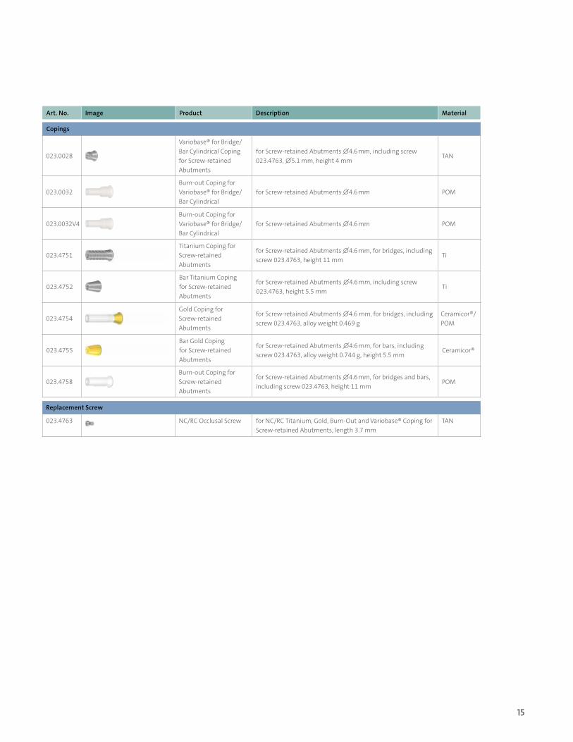
Copings
023.0028
Variobase® for Bridge/Bar Cylindrical Coping for Screw-retained Abutments
for Screw-retained Abutments ∅4.6 mm, including screw 023.4763, ∅5.1 mm, height 4 mm
TAN
023.0032Burn-out Coping for Variobase® for Bridge/Bar Cylindrical
for Screw-retained Abutments ∅4.6 mm POM
023.0032V4Burn-out Coping for Variobase® for Bridge/Bar Cylindrical
for Screw-retained Abutments ∅4.6 mm POM
023.4751Titanium Coping for Screw-retained Abutments
for Screw-retained Abutments ∅4.6 mm, for bridges, including screw 023.4763, height 11 mm
Ti
023.4752Bar Titanium Coping for Screw-retained Abutments
for Screw-retained Abutments ∅4.6 mm, including screw 023.4763, height 5.5 mm
Ti
023.4754Gold Coping for Screw-retained Abutments
for Screw-retained Abutments ∅4.6 mm, for bridges, including screw 023.4763, alloy weight 0.469 g
Ceramicor®/POM
023.4755Bar Gold Coping for Screw-retained Abutments
for Screw-retained Abutments ∅4.6 mm, for bars, including screw 023.4763, alloy weight 0.744 g, height 5.5 mm
Ceramicor®
023.4758Burn-out Coping for Screw-retained Abutments
for Screw-retained Abutments ∅4.6 mm, for bridges and bars, including screw 023.4763, height 11 mm
POM
Art. No. Image Product Description Material
Replacement Screw
023.4763 NC/RC Occlusal Screw for NC/RC Titanium, Gold, Burn-Out and Variobase® Coping for Screw-retained Abutments, length 3.7 mm
TAN
15
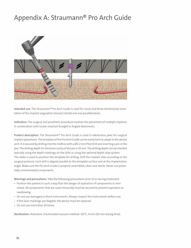
Appendix A: Straumann® Pro Arch Guide
Intended use: The Straumann® Pro Arch Guide is used for visual and three-dimensional orien-tation of the implant angulation (mesial / distal) and oral parallelization.
Indication: The surgical and prosthetic procedure involves the placement of multiple implants in combination with Screw-retained Straight or Angled Abutments.
Product description: The Straumann® Pro Arch Guide is used in edentulous jaws for surgical implant placement. The template of the Pro Arch Guide can be easily bent to adapt to the dental arch. It is secured by drilling into the midline with a ∅2.2 mm Pilot Drill and inserting a pin in the jaw. The drilling depth for the bone cavity of the pin is 10 mm. The drilling depth can be checked optically using the depth markings on the drills or using the optional depth stop system. The slider is used to position the template for drilling. Drill the implant sites according to the surgical protocol. Each drill is aligned parallel to the template surface and at the implantation angle. Make sure the Pro Arch Guide is properly assembled, clean and sterile. Never use poten-tially contaminated components.
Warnings and precautions: Take the following precautions prior to or during treatment: ▪ Position the patient in such a way that the danger of aspiration of components is mini-
mized. All components that are used intraorally must be secured to prevent aspiration or swallowing.
▪ Do not use damaged or blunt instruments. Always inspect the instruments before use. ▪ If the laser markings are illegible, the device must be replaced. ▪ Do not use more than 20 times.
Sterilization: Autoclave, fractionated vacuum method: 132°C, 4 min (30 min drying time).
16

Appendix B: Straumann® Bone Level Bone Profiler
The Bone Level Bone Profiler is used to remove bone coronally to the implant shoulder in the following situations: ▪ deeply placed implants ▪ angulated / tilted implants ▪ scalloped or sloped alveolar ridge
Important: Use the Bone Level Bone Profilers only if the bone walls interfere with the abutment’s emergence profile.
Art. No. Image Product Description Material
Bone Profilers for Bone Level
026.0022 BL Bone Profiler 1 length 23 mm, ∅5.2 mm
Stainless steel
026.0023 BL Bone Profiler 2 length 23 mm, ∅6.6 mm
026.0024 BL Bone Profiler 3 length 23 mm, ∅6 mm
066.0025S BLX Guiding Cylinder for Bone Profiler, length 10.8 mm, ∅2.9 mm TAN
17

1. Screw the BLX Guiding Cylinder (066.0025S) into the implant using an SCS Screwdriver. Hand-tighten the Guiding Cylinder.
2. Choose the Bone Profiler 1, 2 or 3 depending on the abutment emergence profile, the implant position (e.g. subcrestal place-ment, tilted position) and surrounding bone situation (e.g. un-even, scalloped ridge). Table 1 (page 20) shows which Bone Profiler is generally suggested for a particular abutment in situ-ations of deeply (subcrestally) placed implants.
3. Insert the Bone Profiler into the dental hand-piece. Without turning the Bone Profiler, place it over the Guiding Cylinder and slide it down until the Bone Profiler is 1 mm away from the bone. Once in position, drill into the bone not exceeding the maximum rotational speed of 200 rpm. Use intermittent drilling technique with ample irrigation with sterile precooled physiological saline solution. Important: When drilling keep the Bone Profiler and the Guiding Cylinder axially aligned and do not apply any bending forces. Continue drilling until the Bone Profiler reaches the stop collar of the Guiding Cylinder.
Instructions for use For detailed instructions please consult the Instructions for use: Straumann® BL Bone Profilers (701713/en) or at www.ifu.straumann.com.
1
3
18

4
4a
5
5a
4. Remove the Bone Profiler and unscrew the Guiding Cylinder from the implant.
5. Place the abutment and screw it into the implant.
19

Table 1: Abutments and corresponding Bone Level Bone Profilers
Art. No. Product DescriptionBone Profiler 1
026.0022Bone Profiler 2
026.0023Bone Profiler 3
026.0024
062.4722S RB/WB, straight, angle 0°, ∅4.6 mm, gingiva height 1.5 mm, sterile
062.4723S RB/WB, straight, angle 0°, ∅4.6 mm, gingiva height 2.5 mm, sterile
062.4724S RB/WB, straight, angle 0°, ∅4.6 mm, gingiva height 3.5 mm, sterile
062.4725S RB/WB, straight, angle 0°, ∅4.6 mm, gingiva height 4.5 mm, sterile
062.4733S RB/WB, angled, angle 17°, ∅4.6 mm, gingiva height 3.5 mm, sterile
062.4734S RB/WB, angled, angle 17°, ∅4.6 mm, gingiva height 4.5 mm, sterile
062.4735S RB/WB, angled, angle 17°, ∅4.6 mm, gingiva height 5.5 mm, sterile
062.4743S RB/WB, angled, angle 30°, ∅4.6 mm, gingiva height 3.5 mm, sterile
062.4744S RB/WB, angled, angle 30°, ∅4.6 mm, gingiva height 4.5 mm, sterile
062.4745S RB/WB, angled, angle 30°, ∅4.6 mm, gingiva height 5.5 mm, sterile
20
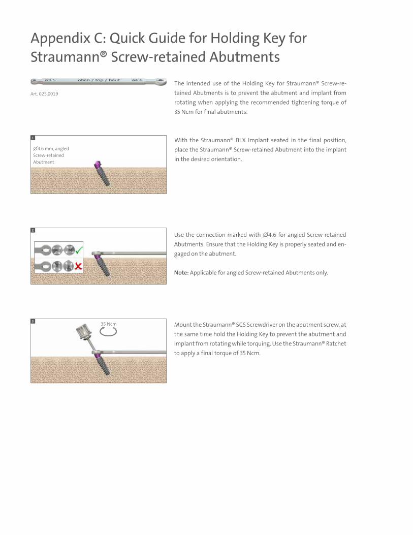
Appendix C: Quick Guide for Holding Key for Straumann® Screw-retained Abutments
The intended use of the Holding Key for Straumann® Screw-re-tained Abutments is to prevent the abutment and implant from rotating when applying the recommended tightening torque of 35 Ncm for final abutments.
With the Straumann® BLX Implant seated in the final position, place the Straumann® Screw-retained Abutment into the implant in the desired orientation.
Use the connection marked with ∅4.6 for angled Screw-retained Abutments. Ensure that the Holding Key is properly seated and en-gaged on the abutment.
Note: Applicable for angled Screw-retained Abutments only.
Mount the Straumann® SCS Screwdriver on the abutment screw, at the same time hold the Holding Key to prevent the abutment and implant from rotating while torquing. Use the Straumann® Ratchet to apply a final torque of 35 Ncm.
Art. 025.0019
∅4.6 mm, angled Screw-retained Abutment
35 Ncm
1
2
3

1 Wismeijer D et al. : ITI Treatment Guide: Loading protocols in Implant Dentistry – Edentulous Patients, Volume 4, 2010, page 223 Patient Consider-ation 2 Wismeijer D et al. : ITI Treatment Guide: Loading protocols in Implant Dentistry – Edentulous Patients, Volume 4, 2010, page 54 Treatment Options for the Edentulous Arch
References
Straumann North American Headquarters Straumann USA, LLC 60 Minuteman Road Andover, MA 01810 Phone 800/448 8168 (US) 800/363 4024 (CA) Fax 978/747 2490 www.straumann.us www.straumann.ca
NAM
LIT.1
292
6/1
9 V
1 D
2
© Straumann USA, LLC 2019. All rights reserved. Straumann® and/or other trademarks and logos from Straumann® that are mentioned herein are the trademarks or registered trademarks of Straumann Holding AG and/or its affiliates. All rights reserved.
ifu.straumann.com