chevrolet and gmc blazer • jimmy • s10 •...
TRANSCRIPT

BVC • 58-26770 • GMC CARS • JCK/MJS/KJE • 8/22/05
7-8 CHEVROLET AND GMCBLAZER • JIMMY • S10 • SONOMA
06025-S10P-C07
06025-S10P-C08
26770_U07.qxd 8/30/05 3:01 PM Page 8

CHEVROLET AND GMCBLAZER • JIMMY • S10 • SONOMA
—
—
BVC • 58-26770 • GMC CARS • JCK/MJS/KJE • 8/22/05
7-9
06025-S10P-C09
26770_U07.qxd 8/30/05 3:01 PM Page 9

BVC • 58-26770 • GMC CARS • JCK/MJS/KJE • 8/22/05
7-10 CHEVROLET AND GMCBLAZER • JIMMY • S10 • SONOMA
06025-S10P-C10
26770_U07.qxd 8/30/05 3:01 PM Page 10

CHEVROLET AND GMCBLAZER • JIMMY • S10 • SONOMA
—
—
BVC • 58-26770 • GMC CARS • JCK/MJS/KJE • 8/22/05
7-11
06025-S10P-C11
26770_U07.qxd 8/30/05 3:01 PM Page 11

BVC • 58-26770 • GMC CARS • JCK/MJS/KJE • 8/22/05
7-12 CHEVROLET AND GMCBLAZER • JIMMY • S10 • SONOMA
06025-S10P-C12
26770_U07.qxd 8/30/05 3:01 PM Page 12

CHEVROLET AND GMCBLAZER • JIMMY • S10 • SONOMA
—
—
BVC • 58-26770 • GMC CARS • JCK/MJS/KJE • 8/22/05
7-13ENGINE REPAIR
Distributor
REMOVAL
The 2.2L engine is equipped with a dis-tributorless ignition.
4.3L Engine
1. Remove or disconnect the following:• Negative battery cable• Air cleaner assembly• Spark plug and coil wires• Electrical connector• Distributor cap
2. Use a grease pencil in order to notethe position of the rotor in relation to thedistributor housing.
3. Mark the distributor housing and theintake manifold location with a grease pen-cil.
4. Remove the mounting clamp holddown bolt and the distributor.
➦As the distributor is being removedfrom the engine, watch the rotor movein a counter-clockwise direction about42 degrees. This will appear as slightlymore than the 1 o’clock position. Notethe position of the rotor segment. Placea second mark on the base of the dis-tributor. This will aid in achievingproper rotor alignment during the dis-tributor installation.
To install:5. If installing a new distributor assem-
bly, place 2 marks on the new distributorhousing in the same location as the 2 markson the original housing.
6. Align the rotor with the second mark.7. Guide the distributor into the engine.8. Align the hole in the distributor
hold-down base over the mounting hole inthe intake manifold.
9. As the distributor is being installed,observe the rotor moving in a clockwisedirection about 42 degrees.
10. Once the distributor is completelyseated, the rotor segment should be alignedwith the mark on the distributor base.
11. If the rotor segment is not alignedwith the number 1 mark, the driven gearteeth and the camshaft have meshed one ormore teeth out of alignment. In order to cor-rect this condition, remove and reinstall thedistributor.
12. Install the distributor mountingclamp bolt and tighten to 18 ft. lbs. (25Nm).
13. Install or connect the following:• Distributor cap• Electrical connector• Spark plug and coil wires• Air cleaner assembly• Negative battery cable
Alternator
REMOVAL
2.2L Engine
1. Remove or disconnect the following:• Passenger side wheel assembly• Alternator brace-to-block bolt, the
brace-to-intake nut and the brace-to-engine stud
• Alternator wiring• Accessory belt• Mounting bolts• Alternator
4.3L Engine
1. Remove or disconnect the following:• Negative battery cable• Air inlet duct, if necessary• Accessory belt• Heater hose brace• Wires• Mounting bolts• Alternator
INSTALLATION
2.2L Engine
Install or connect the following:• Alternator• Mounting bolts. Torque the left bolt
to 22 ft. lbs. (30 Nm) and the rightbolt to 32 ft. lbs. (43 Nm).
• Wires. Torque the battery feed wirenut to 71 inch lbs. (8 Nm).
• Alternator brace. Torque the nutsand bolts to 22 ft. lbs. (30 Nm).
• Accessory belt• Negative battery cable
4.3L Engine
Install or connect the following:• Alternator and loosely install the
mounting bolts• Tighten the rear bolt to 37 ft. lbs.
(50 Nm) and the front bolt to 18 ft.lbs. (25 Nm)
• Tighten the brace-to-alternator andbrace-to-intake retainers to 18 ft. lbs.
(25 Nm). Tighten the brace-to-enginestud nut to 37 ft. lbs. (50 Nm).
• Wires and the battery feed wire nut• Heater hose bracket• Accessory belt• Negative battery cable
Ignition Timing
ADJUSTMENT
The ignition timing is preset and cannotbe adjusted.
Engine Assembly
REMOVAL & INSTALLATION
2.2L Engine
➦In certain cases on some models theA/C system will have to be evacuatedbecause the compressor may need tobe removed from the vehicle to allowclearance for engine removal. On othermodels you maybe able to set the com-pressor and lines to one side and stillhave enough clearance to remove theengine. In this case the system doesnot have to be evacuated because thelines do not have to be disconnectedfrom the compressor. To check if yoursystem has to be evacuated, unplug theelectrical connectors from the com-pressor, then unbolt the compressorassembly. Unfasten any brackets hold-ing the refrigerant lines and try to setthe components aside so that you willhave enough clearance for engineremoval. If there is not enough clear-ance for engine removal you mustrecover the refrigerant from the A/Csystem with an approved recovery sta-tion before attempting to remove theengine from your vehicle. DO NOTattempt this without the proper equip-ment. R-134a should NOT be mixedwith R-12 refrigerant and, dependingon your local laws, attempting to ser-vice this system could be illegal.
1. Disconnect the negative battery cableand properly relieve the fuel system pres-sure.
2. Drain the engine cooling system andthe engine oil into separate drain pans.
3. Remove or disconnect the following:• Hood• Oxygen Sensor (O2S) electrical
connection• Exhaust pipe from the manifold
26770_U07.qxd 8/30/05 3:01 PM Page 13
➦On some models it may also be nec-essary to disconnect the catalytic con-verter from the exhaust pipe.
• Braces from the engine and thetransmission, if equipped
• Starter motor• Transmission and separate it from
the engine or, if necessary, removeit from the vehicle
• Alternator rear brace by unfasteningthe bolt and nuts
• Ground straps from the engineblock
• Drive belt• A/C compressor and bracket. If
possible, set the compressor andbracket to one side without discon-necting the lines.
• Hoses and transmission coolantlines engaged to the radiator
• Radiator• Power steering pump and cap the
power steering lines to avoid con-tamination
• Heater hoses from the heater core• 12 volt supply from the mega fuse,
if necessary• All electrical connections and
wiring harnesses• All vacuum lines• Throttle cable, and if equipped the
cruise control cable• Exhaust Gas Recirculation (EGR)
pipe and the EGR valve• Fuel lines
4. Install a suitable lifting device to theengine.
5. Remove the engine mount bolts andcarefully lift the engine from the vehicle.Pause several times while lifting the engineto make sure no wires or hoses havebecome snagged.
To install:6. Carefully lower the engine into the
vehicle and install the engine mount bolts.Remove the engine lifting device.
7. Install or connect the following:• Fuel lines• 12 volt supply to the mega fuse, if
removed• All vacuum lines, electrical connec-
tions and wiring harnesses• EGR valve and pipe, if removed• Throttle and if equipped, the cruise
control cable• Heater hoses to the heater core• Power steering pump and attach
the lines• A/C compressor• Radiator, all hoses and fluid cooler
lines
• Water pump, if removed• Drive belt• Ground strap to the engine• Alternator rear brace and tighten
the bolt and nuts, if removed• Transmission to the engine• Starter motor, if removed• Braces to the engine and the trans-
mission, if equipped• Exhaust pipe to the manifold• Catalytic converter to the exhaust
pipe, if removed• O2S electrical connection• Battery• Hood
8. Check all powertrain fluid levels andadd, as necessary. Be sure to properly fillthe engine crankcase with clean engine oil.
9. Connect the battery cables and prop-erly fill the engine cooling system.
10. Start and run the engine, then checkfor leaks.
4.3L Engine
1. Drain the engine cooling system2. Drain the engine oil.3. Remove or disconnect the following:
• Negative battery cable• Fuel system pressure• Vacuum reservoir and/or the under-
hood light from the hood, asequipped
• Outer cowl vent grilles• Hood• Oxygen Sensor (O2S) and/or wiring• Exhaust pipes at the manifolds and
loosen the hanger at the catalyticconverter. This is necessary toremove the rear catalytic convertercushion mounts for removal of theexhaust assembly.
• Skid plate, if equipped• Engine-to-transmission pencil
braces• Slave cylinder and position aside, if
equipped• Line clamp at the bell housing• Wiring from the starter• Starter• Transfer case• Oil filter• Engine mount through bolts• Rear engine mount crossbar, nut
and washer• Bell housing bolts, except the
upper left.• Battery ground (negative) cable
from the engine• Front drive axle bolts and roll the
axle downward, on 4WD vehicles• Air cleaner assembly
• Upper radiator shroud• Fan assembly• Drive belt assembly• Water pump pulley• Upper radiator hose• Air conditioning compressor, if
equipped, and position aside withthe lines intact
• Lower radiator hose• Oil cooler and overflow lines from
the radiator, plug the openings toprevent system contamination orexcessive fluid loss
• Radiator and lower radiator shroud• Power steering hoses from the
steering gear, then cap the open-ings to prevent system contami-nation or excessive fluid loss
• Heater hoses from the intake mani-fold and the water pump
• Wiring harness and vacuum linesfrom the engine
• Throttle cables• Remaining bell housing bolt• Fuel lines and the bracket• Ground strap(s) from the rear of the
cylinder head• Front body mount bolts, on 4WD
vehicles4. Support the transmission.5. Install a lifting device and lift the
engine.To install:6. Install or connect the following:
• Engine into the vehicle• Front body mount bolts, on 4WD
vehicles• Ground strap(s) to the rear of the
cylinder head• Fuel lines and the bracket• Upper left bell-housing bolt• Throttle cables• Vacuum lines and wiring harness
connectors• Heater hoses• Power steering hoses• Lower shroud and radiator• Oil cooler lines to the radiator and
overflow hose• Lower radiator hose• Air conditioning compressor to the
engine, if equipped• Upper radiator hose• Water pump pulley• Drive belt assembly• Fan assembly• Upper radiator shroud• Air cleaner assembly• Front drive axle, for 4WD vehicles• Battery ground strap to the engine
block• Remaining bell housing bolts
BVC • 58-26770 • GMC CARS • JCK/MJS/KJE • 8/22/05
7-14 CHEVROLET AND GMCBLAZER • JIMMY • S10 • SONOMA
26770_U07.qxd 8/30/05 3:01 PM Page 14

• Engine mount through-bolts.Torque them to 49 ft. lbs. (66 Nm).
• Rear engine mount crossbar nutand washer. Tighten the nut to 33ft. lbs. (45 Nm).
• Oil filter• Starter motor• Flywheel cover• Clutch slave cylinder, if equipped• Pencil brace and the skid plate, as
equipped• Catalytic converter Y-pipe assembly
and hangers• Hood• Outer cowl vent grilles• Vacuum reservoir and/or the under-
hood light to the hood, as equipped• Negative battery cable
7. Check all powertrain fluid levels andadd, as necessary.
8. Refill the engine crankcase.9. Refill the engine cooling system.
10. Start and run the engine, then checkfor leaks.
Water Pump
REMOVAL & INSTALLATION
1. Disconnect the negative battery cable.2. Drain the engine cooling system.3. Relieve the belt tension and remove
the accessory drive belts or the serpentinedrive belt, as applicable.
4. Remove or disconnect the follow-ing:
• Upper fan shroud• Fan or fan and clutch assembly, as
applicable• Water pump pulley• Coolant hose(s) from the water
pump
➦For the hoses on some engines,removal may be easier if the hose isleft attached until the pump is freefrom the block. Once the pump isremoved from the engine, the pumpmay be pulled (giving a better grip andgreater leverage) from the tight hoseconnection.
• Water pump retainers• Water pump from the engine
✻✻ WARNING
Note the positions of all retainers assome engines will utilize differentlength fasteners in different locationsand/or bolts and studs in differentlocations.
To install:5. Clean the gasket mounting sur-
faces.
➦The water pumps on some of the ear-lier engines covered may have beeninstalled using sealer only, no gasket,at the factory. If a gasket is suppliedwith the replacement part, it should beused. Otherwise, a ¹⁄₈ in. (3mm) beadof RTV sealer should be used aroundthe sealing surface of the pump.
6. Apply sealant to the water pumpretainer threads.
7. Install or connect the following:• Water pump using a new gasket.
Tighten the water pump retainers to18 ft. lbs. (25 Nm) for 2.2L engineor to 30 ft. lbs. (41 Nm) for 4.3Lengine.
• Coolant hose(s)• Water pump pulley• Fan or fan and clutch assembly• Serpentine drive belt (if equipped)
by positioning the belt over thepulleys and carefully allow the ten-sioner back into contact with thebelt
• V-belts (if equipped) and adjust thetension
• Upper fan shroud• Negative battery cable
8. Refill the engine cooling system.9. Run the engine and check for leaks.
Heater Core
REMOVAL & INSTALLATION
1. Disconnect the negative batterycable.
2. Drain the engine cooling system.3. Remove or disconnect the following:
• Heater hoses from the heater core4. Remove the instrument panel as fol-
lows:a. Disable the air bag system.b. Set the parking brake and block the
wheels.c. Disconnect the parking brake
release cable from the parking brakelever.
d. Unfasten the screws that retain theDLC instrument panel left side soundinsulator. Feed the DLC through the holein the sound insulator.
e. Unfasten the right side sound insu-lator panel screws and remove the panel.
f. Unfasten the screws that attach theinstrument panel left side sound insula-tor to the knee bolster and cowl panel.
g. Unfasten the nut that attaches theleft side sound insulator to the accelera-tor pedal bracket.
h. Unplug the remote control doorlock receiver module electrical connector.
i. Remove the door lock receivermodule from the left side sound insula-
CHEVROLET AND GMCBLAZER • JIMMY • S10 • SONOMA
—
—
BVC • 58-26770 • GMC CARS • JCK/MJS/KJE • 8/22/05
7-15
Exploded view of the water pump mounting—2.2L engine
7924JG05
26770_U07.qxd 8/30/05 3:01 PM Page 15

tor. Remove the left side sound insula-tor.
j. Unfasten the screws that attach theinstrument panel center sound insulatorto the knee bolster, instrument panel,heater assembly and floor duct.
k. Remove the center sound insulator.l. Unfasten the screws that attach the
courtesy lamp to the knee bolster.m. Unfasten the screws that attach the
knee bolster to the instrument panel.n. Disconnect the lap cooler duct
from the knee bolster.o. Unplug the lighter electrical con-
nection and remove the knee bolster.p. Unfasten the steering column-to-
instrument panel nuts and lower the col-umn.
q. Unfasten the screws that attach theinstrument panel accessory trim plate tothe instrument panel.
r. Remove the trim plate and unplugall necessary electrical connection.
s. Remove the heater and/or air con-ditioning control assembly.
t. Remove the radio and the storagecompartment assembly (if equipped).
u. If necessary, remove the instrumentcluster.
v. Unfasten the left and right instru-ment panel pivot bolts and the panellower support bolt.
w. Unfasten the speaker grilles retain-ing screws and remove the speaker grilles.
x. Remove the windshield defrostergrille using a flat-bladed prytool. Start atone end of the grille and work your waydown the grille.
y. Unfasten the 4 instrument panelupper support screws.
z. Tag and unplug all necessary elec-trical connections.
aa. Remove the instrument panel fromthe vehicle.5. Remove or disconnect the following:
• Air inlet assembly, if equipped
• Vacuum hoses• Heater assembly studs, from inside
the engine compartment• Blower motor resistor• From inside the heater case assem-
bly, the stud; the stud is locatedbehind the blower motor resistor
• Heater assembly-to-chassis screws• Heater assembly from the vehicle• Access cover screws and cover
from the heater assembly• Heater core from the heater case
assemblyTo install:6. Install or connect the following:
• Heater core to the heater caseassembly
• Access cover to the heater assem-bly and the cover screws
• Heater assembly to the vehicle• Heater assembly-to-chassis screws
and torque them to 40 inch lbs.(4.5 Nm)
• The stud, working inside the heatercase assembly; the stud is locatedbehind the blower motor resistor
BVC • 58-26770 • GMC CARS • JCK/MJS/KJE • 8/22/05
7-16 CHEVROLET AND GMCBLAZER • JIMMY • S10 • SONOMA
View of the heater case assembly
93113G77
View of the heater case cover
93113G78
Exploded view of the water pump assembly mounting—4.3L engine
7924JG06
26770_U07.qxd 8/30/05 3:01 PM Page 16

• Blower motor resistor• Heater assembly studs, working
inside the engine compartment, andtorque them to 17 inch lbs. (1.9 Nm)
• Vacuum hoses• Air inlet assembly, if equipped
7. Install the instrument panel as follows:a. Rest the instrument panel on the
lower pivot studs.b. Attach the electrical connections.c. Install but do not tighten the 4
upper instrument panel support screws.d. Install the left and right panel pivot
bolts. Tighten the bolts to 102 inch lbs.(11.5 Nm).
e. Install the panel lower support bolt.Tighten the bolt to 102 inch lbs. (11.5 Nm).
f. Tighten the upper support screwsto 17 inch lbs. (1.9 Nm).
g. Install the windshield defrostergrille and the speaker grilles.
h. Install the radio and storage com-partment assembly (if equipped).
i. If removed, install the instrumentcluster.
j. Install the heater and/or air condi-tioning control assembly.
k. Attach the electrical connections tothe instrument panel accessory trim plate.
l. Place the trim plate in position andinstall its retaining screws. Tighten thescrews to 17 inch lbs. (1.9 Nm).
m. Place the steering column intoposition and install its retaining nuts.Tighten the nuts to 22 ft. lbs. (30 Nm).
n. Attach the lighter electrical connec-tion and the lap cooler duct to the kneebolster.
o. Place the knee bolster into positionand install its retaining screws. Tightenthe Torx® head screws to 80 inch lbs. (9
Nm) and the hex head screws to 17 inchlbs. (1.9 Nm).
p. Place the courtesy lamp in positionand install its screws. Tighten the screwsto 17 inch lbs. (1.9 Nm).
q. Place the instrument panel centersound insulator in position. Install thescrews that attach the center sound insu-lator to the knee bolster, instrument paneland the floor duct. Tighten the screws to17 inch lbs. (1.9 Nm).
r. Install the screw that attaches thecenter sound insulator to the heaterassembly. Tighten the screw to 13 inchlbs. (1.5 Nm).
s. Install the remote control door lockreceiver module to the instrument panelleft side sound insulator.
t. Attach the door lock receiver elec-trical connection.
u. Install the nut that attaches the leftside sound insulator to the acceleratorpedal bracket. Tighten the nut to 35 inchlbs. (4 Nm).
v. Install the screw that attaches the leftside sound insulator to cowl panel. Tightenthe screw to 13 inch lbs. (1.5 Nm).
w. Install the screws that attach the leftside sound insulator to knee bolster.Tighten the screw to 17 inch lbs. (1.9 Nm).
x. Feed the DLC through the hole in thesound insulator, place the DLC in positionand install its retaining screws. Tighten thescrews to 21 inch lbs. (2.4 Nm).
y. Install the right side sound insula-tor and tighten the screws
z. Connect the parking brake releasecable to the lever.
aa. Enable the air bag system.8. Install the heater hoses to the heater
core.9. Refill the cooling system.
10. Connect the negative battery cable.11. Run the engine to normal operating
temperatures; then, check the climate con-trol operation and check for leaks.
Cylinder Head
REMOVAL & INSTALLATION
2.2L Engine
1. Relieve the fuel system pressure.2. Disconnect the negative battery cable.3. Drain the engine cooling system.4. Remove or disconnect the following:
• Air duct from the air inlet• Upper radiator hose and upper fan
shroud• Radiator assembly• Lower fan shroud• Fan assembly• Drive belt assembly• Water pump pulley• Heater hose from the intake mani-
fold and the thermostat housing• Thermostat housing• Alternator support brace and the
alternator wiring• Air conditioning compressor with
brackets, if equipped, move it asidewithout disconnecting the lines
• Accessory bracket along with thealternator and power steering pump
CHEVROLET AND GMCBLAZER • JIMMY • S10 • SONOMA
—
—
BVC • 58-26770 • GMC CARS • JCK/MJS/KJE • 8/22/05
7-17
View of the heater core
93113G79
Cylinder head bolt torque sequence—2.2L engine
7924JG07
26770_U07.qxd 8/30/05 3:01 PM Page 17

still attached. Be careful not todamage the steering pump lines.
• Throttle cable and cable supportlinkage
• Heater hose from the water pump• Oil fill tube• Exhaust pipe• Oxygen Sensor (O2S)• Exhaust manifold
• Electrical wiring and the vacuumhoses from the upper intake mani-fold
• Upper intake manifold• Wiring from the lower intake mani-
fold• Fuel lines and the spark plug wires• Lower intake manifold• Rocker arm cover
• Rocker arms and pushrods• Engine lift bracket from the rear of
the engine• Cylinder head bolts and studs• Cylinder head from the engine
To install:5. Clean and inspect the gasket mount-
ing surfaces.6. Install or connect the following:
BVC • 58-26770 • GMC CARS • JCK/MJS/KJE • 8/22/05
7-18 CHEVROLET AND GMCBLAZER • JIMMY • S10 • SONOMA
Cylinder head and related components—2.2L engine
7924JG23
26770_U07.qxd 8/30/05 3:01 PM Page 18

• Cylinder head using a new gasket• Cylinder head bolt threads coated
with sealer 1052080. Tighten thebolts within 15 minutes of sealerapplication, in sequence, to 46 ft.lbs. (63 Nm) for long bolts and to43 ft. lbs. (58 Nm) for short bolts;then, tighten all bolts an additional90 degree turn using a torque anglemeter.
• Engine lift bracket• Rocker arms and pushrods• Rocker arm cover• Lower intake manifold• Spark plug wires and the fuel lines• Lower intake manifold and wiring• Upper intake manifold• Vacuum hoses and electrical wiring
to the upper intake• Oil fill tube assembly• Exhaust manifold• Exhaust pipe and O2S• Heater hose to the water pump• Throttle cable support and throttle
cable
• Accessory support bracket andcomponents
• Air conditioning compressor, ifequipped
• Power steering support brace• Alternator support brace and wiring• Thermostat housing and the heater
hose• Water pump pulley and drive belt
assembly• Fan assembly• Radiator and the lower fan
shroud• Upper fan shroud and upper radia-
tor hose• Air inlet ductwork• Negative battery cable
7. Refill the engine cooling system andcheck for leaks.
4.3L Engine
1. Properly relieve the fuel systempressure, then disconnect the negative bat-tery cable.
2. Drain the engine cooling system.3. Remove or disconnect the follow-
ing:• Intake manifold• Exhaust manifold• Alternator and bracket, if removing
the right cylinder head• Cooling fan assembly• Air conditioning compressor (posi-
tion it aside with the refrigerantlines attached)
• Air pipe bracket and nut from therear of the power steering pump ifremoving the left cylinder head
• Engine accessory bracket withpower steering pump (position thepump aside with the lines attached)and brackets, if removing the leftcylinder head
• Wiring harness and clip from therear of the cylinder head
• Coolant sensor wire• Wiring from the spark plugs• Spark plugs, if necessary• Ground wires and if necessary, the
CHEVROLET AND GMCBLAZER • JIMMY • S10 • SONOMA
—
—
BVC • 58-26770 • GMC CARS • JCK/MJS/KJE • 8/22/05
7-19
Cylinder head and related components—4.3L engine
7924JG25
26770_U07.qxd 8/30/05 3:01 PM Page 19

fuel line bracket from the rear of thecylinder head
• Rocker arm cover4. Loosen the rocker arms and remove
the pushrods.
➦If valve train components, such asthe rocker arms or pushrods, are to bereused, they must be tagged orarranged to insure installation in theiroriginal locations.
5. Unfasten the cylinder head bolts byloosening them in the reverse of the torquesequence, then carefully remove the cylin-der head.
To install:6. Carefully clean and inspect the
cylinder head and the gasket mounting sur-faces.
➦The gasket surfaces on both the headand block must be clean of any foreignmatter and free of nicks or heavyscratches. The cylinder bolt threads inthe block and thread on the bolts mustbe cleaned (dirt will affect the bolttorque).
➦DO NOT apply sealer to compositionsteel-asbestos gaskets.
7. If using a steel only gasket, apply athin and even coat of sealer to both sides ofthe gaskets.
8. Place a new gasket over the dowelpins with the bead or the words “This SideUp” facing upward (as applicable), thencarefully lower the cylinder head into posi-tion over the gasket and dowels.
9. Apply a coating of 12346004 orequivalent sealer to the threads of the cylin-der head bolts, then thread the bolts intoposition until finger-tight.
10. Install the bolts in sequence to 22 ft.lbs. (30 Nm). The bolts must then be tight-
ened again in sequence in the followingorder:
a. Short length bolts: (11, 7, 3, 2, 6,10) 55 degrees.
b. Medium length bolts: (12, 13) 65degrees.
c. Long length bolts: (1, 4, 8, 5, 9) 75degrees.11. Install or connect the following:
• Pushrods, secure the rocker armsand adjust the valves
• Rocker arm cover• Spark plugs, if removed• Spark plug wires• Attach the fuel line bracket (if
removed) and ground wires to therear of the head and tighten thebolts to 22 ft. lbs. (30 Nm)
• Air conditioning compressor andbracket, if the left cylinder head wasremoved
• Alternator and bracket, if the rightcylinder head was removed
• Engine accessory bracket withpower steering pump if the leftcylinder head was removed
• Air pipe bracket and nut to the rearof the power steering pump (ifequipped), if the left cylinder headwas removed. Tighten the nut to 30ft. lbs. (41 Nm).
• A/C compressor, if the left cylinderhead was removed
• Cooling fan assembly, if the leftcylinder head was removed
• Wiring harness and clip to the rearof the cylinder head
• Coolant sensor wire• Exhaust manifold• Intake manifold• Negative battery cable
12. Properly refill the engine coolingsystem.
13. Run the engine to check for leaks.
Rocker Arms
REMOVAL & INSTALLATION
2.2L Engine
1. Remove or disconnect the following:• Rocker arm cover• Rocker arm retaining nut, arm and
ball• Pushrod, if necessary
➦Valvetrain components, beingreused, must be installed in their origi-nal positions. If removed, be sure totag or arrange all rocker arms andpushrods to assure proper installation.
To install:2. Inspect the rocker arms, balls and
pushrods for damage or wear and replaceas necessary.
3. Check the rocker arms, balls and theirmating surfaces. Be sure the surfaces aresmooth and free from scoring or other dam-age.
4. Check the rocker arm areas that con-tact the valve stems and the sockets thatcontact the pushrods, be sure these areasare smooth and free of both damage andwear.
5. Be sure the pushrods are not bentwhich can be determined by rolling them ona flat surface. Check the ends of thepushrods for scoring or roughness
6. Inspect the rocker arm bolts forthread damage. Check the rocker arm boltsin the shoulder area for contact damagewith the rocker arm.
7. Install or connect the following:• Pushrods making sure they are
seated within the lifters, if removed• New rocker arms and balls by coat-
BVC • 58-26770 • GMC CARS • JCK/MJS/KJE • 8/22/05
7-20 CHEVROLET AND GMCBLAZER • JIMMY • S10 • SONOMA
Cylinder head bolt torque sequence—4.3L engine
7924JG08
Exploded view of the rocker arm assem-bly—2.2L engine
7924JG45
26770_U07.qxd 8/30/05 3:01 PM Page 20

ing the friction surfaces using Dri-Slide Molykote® or equivalent pre-lube
✻✻ WARNING
When tightening a rocker armretainer, be sure the lifter for thatvalve is resting on the base circle ofthe camshaft and not on the lobe,otherwise the valve train can bedamaged. Do not over-tighten theretainers.
• Rocker arms and ball. Tighten thenuts to 18 ft. lbs. (25 Nm).
• Rocker arm cover8. Start and run the engine to check for
leaks.
4.3L Engine
1. Remove or disconnect the following:• Rocker arm cover(s)• Rocker arm nut, rocker arm and
ball washer
➦If only the pushrod is to be removed,loosen the rocker arm nut, swing therocker arm to the side and remove thepushrod.
• Pushrod(s)To install:2. Inspect and replace components if
worn or damaged.3. Coat the bearing surfaces of the
rocker arms and the rocker arm ball wash-ers with Molykote® or equivalent pre-lube.
4. Install or connect the following:• Pushrods making sure they seat
properly in the lifter• Rocker arms, ball washers and the
nuts
➦The 4.3L engines are equipped withscrew-in rocker arm studs with positivestop shoulders.
• Rocker arm adjusting nuts andhand-tighten
5. Rotate the crankshaft balancer toposition the crankshaft balancer alignmentmark (1) 57-63 degrees clockwise or coun-terclockwise from the engine front coveralignment tab (2).
6. Tighten the rocker arm bolts to 22 ft.lbs. (30 Nm). No further adjustment is nec-essary or possible.
7. Install the rocker arm cover(s).8. Start and run the engine, then check
for leaks and for proper ignition timingadjustment.
Intake Manifold
REMOVAL & INSTALLATION
2.2L Engine
1. Remove or disconnect the follow-ing:
• Negative battery cable and removethe air cleaner resonator.
• Three vacuum hoses from thethrottle body
• Throttle cable support bracket andthe throttle body assembly
• Upper fan shroud and disconnect
the vacuum brake booster hose, ifnecessary
• Exhaust Gas Recirculation (EGR)pipe-to-manifold bolts and the EGRpipe-to-EGR adapter bolt, and theEGR pipe.
• EGR adapter• Idle Air Control (IAC) motor con-
nector• Idle Air Control (IAC) motor• Manifold Absolute Pressure (MAP)
sensor connector• Throttle Position (TP) sensor con-
nector• Fuel injector harness connector• Right fender wheelhouse extension• Retainers from the engine harness
bracket, the transmission filler tube(if equipped) and the fuel systemevaporator pipe
• Fuel pipes from the fuel rail• Accelerator cable and if equipped,
the cruise control cable• Spark plug wires from the plugs• Spark plug wire harness retainer
from the heater hose pipe and setaside the harness
• Alternator rear brace by accessingthe retaining nuts and bolts throughthe wheelhouse, if necessary
• Engine wiring harness bracket
CHEVROLET AND GMCBLAZER • JIMMY • S10 • SONOMA
—
—
BVC • 58-26770 • GMC CARS • JCK/MJS/KJE • 8/22/05
7-21
Exploded view of the rocker arm assem-bly—4.3L engine
7924JG46
Positioning the crankshaft balancer—4.3L engine
06025-S10P-G01
26770_U07.qxd 8/30/05 3:01 PM Page 21

located at the rear of the cylinderhead (if necessary), by unfasteningthe bracket-to-valve cover andbracket-to-cylinder head retainers,then slide the bracket off the bolt atthe rear of the cylinder head
• Intake manifold bolts• Fuel rail bracket• Intake manifold and gasket
To install:2. Carefully remove all traces of gasket
material from the mating surfaces. Checkthe EGR passage to be sure it is free ofexcessive carbon deposits and clean, asnecessary.
3. Install or connect the following:• Lower intake manifold using a new
gasket, then tighten the retainingbolts to 17 ft. lbs. (24 Nm) usingthe sequence illustrated
• Engine wiring harness bracket, ifremoved. Tighten the bracket-to-valve cover bolts to 88 inch lbs.
(10 Nm) and the bracket-to-cylin-der head bolt to 18 ft. lbs. (25 Nm).
• Generator rear brace, if removed.Tighten the nuts and bolts to 18 ft.lbs. (25 Nm).
• Spark plug wire harness andretainer and attach the spark plugwires to the plugs
• Throttle body assembly, if removedand the throttle cable supportbracket
• Three vacuum lines to the throttlebody
• Accelerator cable and if equipped,the cruise control cable
• Fuel lines• Retainers to the engine harness
bracket, the transmission filler tube(if equipped) and the fuel systemevaporator pipe
• IAC motor connector• MAP sensor connector• TP sensor connector
• Fuel injector harness connector• Wheelhouse extension• EGR adapter and tighten the retain-
ers to 97 inch lbs. (11 Nm)• EGR pipe to the EGR adapter and
tighten the bolt to 18 ft. lbs. (25Nm)
• EGR pipe-to-intake manifold boltsand tighten the bolts to 89 inch lbs.(10 Nm)
• Upper fan shroud and the brakebooster hose
• Air cleaner resonator and connectthe negative battery cable.
4. Start the engine and check for leaks.
4.3L Engine
➦If only the upper intake manifold isbeing removed, the fuel system pres-sure does not need to be released.ALWAYS release the pressure beforedisconnecting any fuel lines.
1. Remove the engine cover, ifequipped
2. Properly relieve the fuel systempressure.
3. Drain the engine cooling system.4. Remove or disconnect the follow-
ing:• Negative battery cable• Air cleaner and air inlet duct• Wiring harness connectors and
brackets• Throttle linkage from the upper
intake manifold• Ignition coil• Fuel lines and bracket from the rear
of the lower intake manifold• Brake booster vacuum hose at the
upper intake manifold• Positive Crankcase Ventilation
(PCV) hose at the rear of the upperintake manifold
• Vacuum hoses from both the frontand rear of the upper intake
• Purge solenoid and bracket• Upper intake manifold• High Voltage Switch (HVS) assem-
bly• Upper radiator hose at the thermo-
stat housing• Heater hose at the lower intake
manifold• Wiring harnesses and brackets.• Automatic transmission dipstick
tube• Exhaust Gas Recirculation (EGR)
tube, clamp and tube• Air conditioning compressor
bracket-to-lower intake manifoldpencil brace
BVC • 58-26770 • GMC CARS • JCK/MJS/KJE • 8/22/05
7-22 CHEVROLET AND GMCBLAZER • JIMMY • S10 • SONOMA
Typical intake manifold mounting—2.2L engine shown
91113G02
Intake manifold bolt tightening sequence—2.2L engine
91113G03
26770_U07.qxd 8/30/05 3:01 PM Page 22

• Alternator bracket bolts near thethermostat housing
• Lower intake manifold5. Insert clean rags into the openings in
the cylinder head to prevent dirt and debrisfrom entering the engine.
6. Clean the gasket mounting surfaces.Be sure to inspect the manifold for warpageand/or cracks. If necessary, replace it.
To install:7. Remove the rags from the cylinder
heads.8. Position the gaskets on the cylinder
head with the port blocking plates to therear and the This Side Up stamps facingupward. Then apply a ³⁄₁₆ in. (5mm) bead ofRTV sealant on the front and rear of theengine block at the block-to-manifold mat-ing surface. Extend the bead ¹⁄₂ in. (13mm)up each cylinder head to seal and retain thegaskets.
9. Install the lower intake manifold.Tighten the bolts in sequence and in 3steps, as follows:
a. Step 1: 26 inch lbs. (3 Nm).b. Step 2: 106 inch lbs. (12 Nm).
c. Step 3: 11 ft. lbs. (15 Nm).10. Install or connect the following:
• Alternator bracket bolt near thethermostat housing
• EGR tube, clamp and bolt• Wiring harness to the lower mani-
fold components, including theinjector, EGR valve and ECT sensor
• Air conditioning compressorbracket-to-the lower intake mani-fold pencil braces
• Transmission oil dipstick tube, ifnecessary
• Fuel supply and return lines to therear of the lower intake
11. Temporarily reattach the negativebattery cable, then pressurize the fuel sys-tem (by cycling the ignition without startingthe engine) and check for leaks.
12. Disconnect the negative batterycable.
13. Install or connect the following:• Heater hose to the lower intake• Upper radiator hose to the thermo-
stat housing• Vacuum hoses to the upper and
lower intake manifold• New upper intake manifold gasket,
making sure the green sealing linesare facing upward
• Upper intake manifold being carefulnot to pinch the fuel injector wiresbetween the manifolds
• Manifold retainers. Tighten them to88 inch lbs. (10 Nm) using twopasses.
• Purge solenoid and bracket• Brake booster vacuum hose at the
upper intake manifold.• PCV hose to the rear of the upper
intake manifold• Vacuum hoses to both the front and
rear of the manifold assembly• Throttle linkage to the upper intake• Ignition coil• Wiring to the upper intake compo-
nents including the TP sensor, IACmotor, MAP sensor and the IMTV.
• Plastic cover• Air cleaner and air inlet duct• Negative battery cable
14. Refill the engine cooling system.
Exhaust Manifold
REMOVAL & INSTALLATION
2.2L Engine
1. Remove or disconnect the following:• Negative battery cable
CHEVROLET AND GMCBLAZER • JIMMY • S10 • SONOMA
—
—
BVC • 58-26770 • GMC CARS • JCK/MJS/KJE • 8/22/05
7-23
Intake manifold and related components—4.3L engine
7924JG26
Lower intake manifold tightening sequence—4.3L engines
9358KG01
26770_U07.qxd 8/30/05 3:01 PM Page 23

• Air cleaner and duct work• Oxygen Sensor (O2S) from the
manifold, if replacing it• Drive belt• Oil fill tube assembly• Heater hose brace• Power steering brace and set the
pump aside• Air conditioning pencil and rear
braces. Set the compressor asidewithout disconnecting the lines
• Exhaust manifold nuts• Exhaust manifold
To install:2. Clean the exhaust manifold retainer
threads and the gasket the mating surfaces.3. Install or connect the following:
• Exhaust manifold using a new gas-ket. Torque the nuts to 115 inchlbs. (13 Nm).
• Exhaust pipe to the manifold• Air conditioning pencil and rear
braces
• Heater hose• Power steering and heater hose
braces• Oil fill tube assembly• O2S. Torque the sensor to 31 ft.
lbs. (42 Nm), if necessary.• Drive belt• Air cleaner and duct work• Negative battery cable
4.3L Engine
1. Remove or disconnect the follow-ing:
• Negative battery cable
➦It will be easier if the vehicle is onlysupported to a height where underhoodaccess is still possible, the vehiclemay be left in position for the entireprocedure. If the vehicle is raised toohigh for underhood access, it will haveto lowered, raised and lowered againduring the procedure.
• Breather tube from the air cleaneroutlet duct, if removing the left sidemanifold
• Air cleaner outlet duct retainingwingnut, if removing the left sidemanifold
• Intake Air Temperature (IAT) sensorharness connector, if removing theleft side manifold
• Air cleaner outlet duct from thethrottle body, if removing the leftside manifold
• Exhaust pipe from the exhaustmanifold. It may be necessary toremove the tires to gain access tothe rear manifold bolts.
• Engine oil dipstick tube bolt, ifremoving the right side manifold
• Exhaust Gas Recirculation (EGR)inlet pipe from the left side mani-fold, if necessary
• Engine Coolant Temperature (ECT)sensor electrical connection
• Upper radiator support hose andnut
• Steering intermediate shaft, ifremoving the left side manifold
• Wheel house extension, if removingthe right side manifold
• Spark plugs wires from the plugs• Nuts attaching the secondary air
injection pipe to the manifold• Air injection pipe and gasket• Locktangs (unbend), the exhaust
manifold retaining bolts, washersand tab washers
• Heat shields• Exhaust manifold• Old gaskets and discard
To install:2. Using a putty knife, clean the gasket
mounting surfaces. Inspect the exhaustmanifold for distortion, cracks or damage;replace if necessary.
3. Apply a threadlock such as GM12345493 to the threads of the manifoldretainers prior to installation.
4. Install or connect the following:• Exhaust manifold to the cylinder
using a new gasket, then tightenthe to 11 ft. lbs. (15 Nm) and thento 22 ft. lbs. (30 Nm). Once thebolts are tightened, bend the tabson the washers back over the headsof all bolts in order to lock them inposition.
• Spark plug wires to the plugs• Fender wheelhouse extension and
the tire assembly, if removed• Secondary air injection pipe with a
NEW gasket to the manifold andtighten the nuts to 18 ft. lbs. (25Nm), if removed
• EGR inlet pipe, if removed• ECT sensor electrical connection, if
removed• Upper radiator hose support and
nut, if removed• Steering intermediate shaft, if
removed (left side manifold only)
• Engine oil dipstick tube bolt to 106inch lbs. (12 Nm), if removed
• Exhaust pipe to the manifold• Air cleaner outlet duct to the
throttle body, if removed• IAT sensor harness connector, if
removed
BVC • 58-26770 • GMC CARS • JCK/MJS/KJE • 8/22/05
7-24 CHEVROLET AND GMCBLAZER • JIMMY • S10 • SONOMA
Exhaust manifold mounting—2.2L engine7924JG47
Exploded view of the exhaust manifold mounting—4.3L engine, left side shown
71461-SONO-G01
26770_U07.qxd 8/30/05 3:01 PM Page 24

• Air cleaner outlet duct retainingwingnut, if removed
• Breather tube to the air cleaner out-let duct, if removed
• Negative battery cable
Camshaft and Valve Lifters
REMOVAL & INSTALLATION
2.2L Engine
1. Properly relieve the fuel system pres-sure.
2. Disconnect the negative battery cable.3. Drain the engine cooling system and
the engine oil.4. Remove or disconnect the following:
• Radiator• Rocker arm cover• Cylinder head• Anti-rotation bracket bolts and
brackets• Valve lifters• Oil pump drive retaining bolt and
the drive by lifting and twisting• Camshaft Position (CMP) sensor, if
equipped• Crankshaft pulley and hub• Drive belt idler pulley• Timing cover from the engine• Timing chain and camshaft
sprocket• Camshaft thrust plate• Camshaft by pulling it straight out
of the engine, while turning itslightly as it is withdrawn and tak-ing care not to damage the bear-ings.
To install:5. Inspect the camshaft, journals and
lobes for wear and replace, if necessary.6. If removed, use the camshaft bearing
tool to install a new set of bearings.7. Coat the camshaft lobes and journals
with a high viscosity oil with zinc such asGM 12345501.
8. Install or connect the following:• Camshaft by turning it slightly from
side-to-side as it is inserted• Thrust plate. Torque the bolts to
106 inch lbs. (12 Nm).• Timing chain and camshaft
sprocket• Timing cover• Serpentine drive belt idler pulley• Crankshaft pulley and hub
• Oil pump drive by inserting whiletwisting. Torque the fasteners to 18ft. lbs. (25 Nm).
• Valve lifters and the anti-rotationbrackets
• Cylinder head. Torque the bolts to46 ft. lbs. (62 Nm) plus an addi-tional 90 degrees turn.
• Rocker arm cover• Radiator• Negative battery cable
9. Refill the engine cooling system.
4.3L Engine
1. Properly relieve the fuel systempressure.
2. Disconnect the negative batterycable.
3. Drain the engine cooling system.4. Discharge and recover the refrigerant
from the air conditioning system.5. Remove or disconnect the follow-
ing:• Radiator• Air conditioning condenser• Rocker arm covers• Intake manifold assembly• Rocker arms, pushrods and lifters• Crankshaft pulley and hub• Engine front (timing) cover
6. Align the timing marks on the crank-shaft and camshaft sprockets.
7. Remove or disconnect the following:• Camshaft sprocket and timing
chain• Balance shaft drive gear, if
equipped• Camshaft thrust plate• Camshaft by installing the sprocket
bolts or longer bolts the camshaftend to act as a handle; then,remove the camshaft while turningslightly from side to side, as neces-sary.
CHEVROLET AND GMCBLAZER • JIMMY • S10 • SONOMA
—
—
BVC • 58-26770 • GMC CARS • JCK/MJS/KJE • 8/22/05
7-25
The new exhaust manifold gasket may have tab, which will help hold the gasket and bolts inplace
71461-SONO-G02
Remove the camshaft thrust plate andwithdraw the camshaft from the engine—2.2L engine
7924JG49
Thread 3 long bolts into the camshaft touse as a handle, then withdraw it from theengine
7924JG50
26770_U07.qxd 8/30/05 3:01 PM Page 25

➦Take care not to damage thecamshaft bearings when removing thecamshaft.
To install:8. Lubricate the camshaft journals with
clean engine oil or a suitable pre-lube.9. Install or connect the following:
• Camshaft being extremely carefulnot to contact the bearings with thecam lobes
• Thrust plate. Torque the bolts to106 inch lbs. (12 Nm).
• Balance shaft drive gear, ifequipped
• Timing chain and camshaftsprocket
• Engine front (timing) cover• Crankshaft pulley and hub• Valve lifters, pushrods and rocker
arms. Adjust the valve clearance.• Intake manifold assembly• Rocker arm covers• Radiator• Negative battery cable
10. Refill the engine cooling system.
Valve Lash
ADJUSTMENT
2.2L Engine
Because the rocker arm fasteners aresecured and tightened, valve lash is notadjustable on the 2.2L engine. If a valve-train problem is suspected, check that therocker arm nuts are tightened to 18 ft. lbs.(25 Nm). Be very careful not to over-tighten the rocker arm nuts. ONLY tightenthe nuts when the hydraulic lifter is restingon the base circle of the camshaft and notwhen it is held upward on the lobe. Whenvalve lash falls out of specification (valvetap is heard), replace the rocker arm,pushrod and hydraulic lifter on the offend-ing cylinder.
4.3L Engine
The 4.3L engines are equipped withscrew-in rocker arm studs with positivestop shoulders. Because the shoulders thatallow the rocker arms to be tightened intoproper position, no adjustments are neces-sary or possible. If a valvetrain problem issuspected, check that the rocker arm nutsare tightened to 22 ft. lbs. (30 Nm). Whenvalve lash falls out of specification (valvetap is heard), replace the rocker arm,pushrod and hydraulic lifter on the offend-ing cylinder.
Starter Motor
REMOVAL & INSTALLATION
2 Wheel Drive (2WD) Models
2.2L ENGINE1. Remove or disconnect the following:
• Negative battery cable• Front exhaust pipe, if necessary for
access• Starter heat shield, if equipped• Brace rod from the front of the
engine and the bell housing• Drivers side wheel to access the
starter motor wires and the startermotor attaching bracket-to-enginebolt through the opening in thewheel well
• Wires from the starter solenoid• Attaching bracket-to-engine mount
bolt• Starter-to-engine block bolts. When
removing the last bolt, be sure to
support the starter to keep it fromfalling and possibly injuring you.
• Starter and shims (if equipped)from the vehicle
• Bracket from the starter assembly, ifequipped
To install:2. Install or connect the following:
• Bracket to the starter, if removed.Tighten the bracket nuts to 97 inchlbs. (11 Nm).
• Starter and shims (if equipped) intoposition in the vehicle and threadone of the retaining bolts to hold itin position.
• Bracket-to-engine mount bolt(loosely), if equipped
• Starter mounting bolt, then tightenall mounting fasteners to 32 ft. lbs.(43 Nm)
• Wiring to the solenoid• Brace rod and tighten the retainers• Front exhaust pipe and tighten the
fasteners, if removed• Starter heat shield, if equipped
BVC • 58-26770 • GMC CARS • JCK/MJS/KJE • 8/22/05
7-26 CHEVROLET AND GMCBLAZER • JIMMY • S10 • SONOMA
Starter motor and related components—2.2L engine
88452G08
26770_U07.qxd 8/30/05 3:01 PM Page 26

• Driver’s side wheel, if removed• Negative battery cable
4.3L MODELS1. Remove or disconnect the following:
• Negative battery cable• Wires from the starter solenoid• Starter motor mounting bolts• Starter motor and if equipped, the
shimsTo install:2. Install or connect the following:
• Starter motor into position• Starter motor inboard bolt but do
not tighten it at this time• Starter motor shims, if equipped• Outboard starter motor bolt. Tighten
the bolts to 32 ft. lbs. (43 Nm).• Wires to the solenoid• Negative battery cable
4 Wheel Drive (4WD) Models
1. Remove or disconnect the following:• Negative battery cable
➦In some cases it may be easier toaccess the starter motor bolts if youraise the vehicle and remove the wheelassembly.
• Wheel assembly, if necessary• Engine mounts• Transmission mount and support
the transmission assembly• Starter-to-engine bolts and support
the starter2. Rotate the starter as necessary for
access, then tag and disconnect the sole-noid wiring.
3. Carefully lower the starter and shims(if equipped) from the vehicle. Note thelocation of any shims for installation pur-poses.
4. If necessary, remove the shield fromthe starter assembly.
To install:5. Install or connect the following:
• Starter into position in the vehiclealong with any shims (making surethey are in their original positions),then tighten the mounting bolts to37 ft. lbs. (50 Nm).
• Shield to the starter assembly andtighten the retaining nuts to 106inch lbs. (12 Nm), if removed
• Wiring to the solenoid• Transmission mount and remove
the supports• Secure the engine mounts, then
remove the lifting device• Wheel assembly, if removed
6. Connect the negative battery cable.
Oil Pan
REMOVAL & INSTALLATION
2.2L Engine
1. Drain the engine oil.2. Remove or disconnect the following:
• Engine• Clutch pressure plate and disc, if
equipped• Flywheel• Oil pan retainers and the pan
To install:3. Clean the gasket mating surfaces4. Install or connect the following:
• New gasket and seal onto the oilpan using a thin bead of sealant ateither side of the seal
• Oil pan. Torque the bolts to 89inch. lbs. (10 Nm).
• Flywheel
• Pressure plate and disc, ifequipped
• Engine
4.3L Engine
2WD MODELS1. Drain the engine oil.2. Remove or disconnect the follow-
ing:• Engine• Oil level sensor, if equipped, and
discard• Oil pan retainers (nuts, studs
and/or bolts) and rail reinforce-ments, if equipped
• Oil pan• Rubber bell housing plugs and
gasketTo install:3. Clean the gasket mounting surfaces.
➦The alignment between the rear ofthe oil pan and the rear of the block iscritical. The oil pan must be flush orslightly forward of the rear of the blockto allow for proper alignment with thetransmission housing. Use a feelergauge to measure the clearancebetween the 3 oil pan-to-transmissioncontact points. If the clearance exceeds0.011 in. (0.3mm) at any of the 3points, realign the oil pan.
4. Apply sealant to the oil pan rail whereit contacts the timing cover-to-block joint(front) and the crankshaft rear seal retainer-to-block joint (rear). Continue the bead ofsealant about 1 in. (25mm) in both direc-tions from each of the 4 corners.
5. Install or connect the following:• Rubber bell housing plugs, if
equipped• Oil pan using a new gasket
➦The alignment between the rear ofthe pan and rear of the block is critical.The two surfaces must be flush to allowfor proper alignment with the transmis-sion housing.
6. Use a feeler gauge to check the clear-ance between the oil pan-to-transmissioncontacts. If clearance exceeds 0.011 inch(0.3mm) at any of the three contact points,readjust the pan until the clearance is withinspecification.
7. Once the pan is in its correct positiontighten the retainers to 18 ft. lbs. (25 Nm)using the proper sequence.
8. Install a new oil level sensor, if usedand tighten to 115 inch lbs. (13 Nm).
9. Install the engine into the vehicle.Refill the crankcase with fresh oil. Start the
CHEVROLET AND GMCBLAZER • JIMMY • S10 • SONOMA
—
—
BVC • 58-26770 • GMC CARS • JCK/MJS/KJE • 8/22/05
7-27
The starter motor on 4.3L engines isretained by two long bolts
88452G09
Oil pan mounting—2.2L engine7924JG51
26770_U07.qxd 8/30/05 3:01 PM Page 27

engine, establish normal operating tempera-tures and check for leaks.
4WD MODELS1. Disconnect the negative battery
cable.2. Drain the engine crankcase oil.3. Remove or disconnect the following:
• Dipstick• Drivebelt splash shield, the front
axle shield and the transfer caseshield
• Front skid plate and the flywheelcover
• Left and right engine mountthrough-bolts
4. Raise the engine using a liftingdevice and block in position. This may beaccomplished using large wooden blocksbetween the motor mounts and brackets.
➦Use extreme caution when blockingthe engine in position. Get out fromunder the vehicle and rock the engineslightly once the blocks are in place tobe sure the engine is properly sup-ported.
5. Remove or disconnect the following:• Oil cooler line• Pitman arm bolt and pitman arm
• Idler arm bolts and idler arm• Front differential through-bolts• Front driveshaft, if necessary• Differential assembly by rolling it
forward for clearance
• Starter motor• Oil pan bolts, nuts and reinforce-
ments• Oil pan and discard the gasket
To install:6. Clean the gasket mounting surfaces.
➦The alignment between the rear ofthe oil pan and the rear of the block iscritical. The oil pan must be flush orslightly forward of the rear of the blockto allow for proper alignment with thetransmission housing. Use a feelergauge to measure the clearancebetween the 3 oil pan-to-transmissioncontact points. If the clearance exceeds0.011 in. (0.3mm) at any of the 3points, realign the oil pan.
BVC • 58-26770 • GMC CARS • JCK/MJS/KJE • 8/22/05
7-28 CHEVROLET AND GMCBLAZER • JIMMY • S10 • SONOMA
Oil pan mounting—4.3L engine
7924JG52
If the clearance between the 3 oil pan-to-transmission contact points exceeds 0.011in. (0.3mm) at any of the 3 points, realignthe oil pan—4.3L engine
7924JG16
Tighten the bolts in sequence to prevent warping the sealing surface of the oil pan—4.3Lengine
7924JG17
26770_U07.qxd 8/30/05 3:01 PM Page 28

7. Apply sealant to the oil pan railwhere it contacts the timing cover-to-blockjoint (front) and the crankshaft rear sealretainer-to-block joint (rear). Continue thebead of sealant about 1 in. (25mm) in bothdirections from each of the 4 corners.
8. Install or connect the following:• Oil pan, using a new gasket.
Tighten the retainers, in sequence,to 18 ft. lbs. (25 Nm).
• Starter motor• Differential by rolling it back into
position• Front driveshaft• Front differential through-bolts• Idler arm and secure using the
retaining bolts• Pitman arm and secure using the
bolts• Transfer case shield• Flywheel cover• Front skid plate• Front axle shield• Drive belt splash shield• Dipstick• Negative battery cable
9. Refill the engine crankcase.10. Start the engine and check for leaks.
Oil Pump
REMOVAL & INSTALLATION
1. Remove or disconnect the following:• Oil pan• Oil pump and the pickup
tube/shaft, if equipped• Extension shaft and retainer from
the pump, if necessary for the 2.2Lengine
➦Be careful not to crack the retainer.
To install:2. Inspect the pins (oil pump locator) for
damage, and replace the pins if required.To install:3. For the 2.2L engine, if the extension
shaft was removed, heat the extension shaftretainer in hot water, then install the shaftand retainer to the oil pump. Be sure theretainer does not crack during installation.
4. Ensure that the pump pickup tube istight in the pump body. If the tube shouldcome loose, oil pressure will be lost and oilstarvation will occur. If the pickup tube isloose it should be replaced.
5. If the pump has been disassembledand is being replaced or for any reason oilhas been removed, it must be primed. It caneither be filled with oil before installing thecover plate and oil kept within the pumpduring handling or the entire pump cavitycan be filled with petroleum jelly.
✻✻ WARNING
If the pump is not primed, the enginecould be damaged upon start up.
➦Do not reuse the oil pump driveshaftretainer. During assembly, install aNEW oil pump driveshaft retainer.
6. Install or connect the following:• Oil pump. Tighten oil pump/pickup
tube retainer(s) to 32 ft. lbs. (44Nm) for the 2.2L engine or to 65 ft.lbs. (90 Nm), for the 4.3L engine.
➦If the oil pump does not build up oilpressure almost immediately, removethe pan and check for a loose oil pump-to-pickup tube attachment. If necessarydismantle the pump and pack the pumpcavity with petroleum jelly.
• Oil pan7. Refill the crankcase.8. Disable the ignition system; crank
engine for approximately 10 seconds to aidin priming the oil pump and reducing therisk of engine damage.
✻✻ WARNING
Running the engine without measur-able oil pressure will cause exten-sive damage.
Rear Main Seal
REMOVAL & INSTALLATION
2.2L Engine
Please note that the transmission assem-bly and transfer case, if equipped, must beremoved to perform this procedure.
1. Remove or disconnect the following:• Negative battery cable• Transmission assembly and trans-
fer case, if equipped• Flexplate, if equipped• Clutch assembly and flywheel, if
equipped• Crankshaft seal by prying it from out
➦Be careful not to damage the crank-shaft seal surface with the prying tool.
To install:2. Install the new rear seal by lubricating
it with engine oil and using a seal tool J-34686.
CHEVROLET AND GMCBLAZER • JIMMY • S10 • SONOMA
—
—
BVC • 58-26770 • GMC CARS • JCK/MJS/KJE • 8/22/05
7-29
Exploded view of the oil pump mounting—2.2L engine
7924JG18
On 4.3L engines, inspect the pins (oilpump locator) for damage, and replacethe pins if required
71461-SONO-G03
26770_U07.qxd 8/30/05 3:01 PM Page 29

3. Slide the seal over the mandrel untilthe dust lip bottoms squarely against thetool collar.
4. Align the dowel pin of the tool withthe dowel pinhole in the crankshaft andattach the tool to crankshaft.
5. Tighten the T-handle of the tool topush the seal into the bore. Continue untilthe tool collar is flush against the block.
6. Loosen the T-handle completely.Remove the attaching screws and tool.Check to be sure the seal is seated squarelyin the bore.
7. Install or connect the following:• Flywheel/clutch assembly or flex-
plate• Transmission assembly and trans-
fer case, if equipped• Negative battery cable
8. Start the engine and check for leaks.
4.3L Engine
Please note that the transmission assem-bly and transfer case, if equipped, must beremoved to perform this procedure.
1. Remove or disconnect the following:
• Negative battery cable• Transfer case, if equipped• Transmission• Clutch assembly/flywheel or flex-
plate2. Remove the crankshaft rear oil seal by
inserting a suitable prying tool into thenotches provided in the seal retainer andprying the seal out. Take care not to damagethe crankshaft sealing surface.
To install:3. Inspect the crankshaft for grit, rust or
burrs and correct as necessary.4. Clean the running surface of the
crankshaft with a non-abrasive cleaner.5. Install or connect the following:
• New rear seal lubricated withengine oil and a seal installer
• Flywheel and clutch or flexplate• Transmission• Transfer case, if equipped• Negative battery cable
6. Start the engine and verify no oilleaks.
Timing Chain, Sprockets, FrontCover and Seal
REMOVAL & INSTALLATION
Front Cover and Seal
2.2L ENGINE1. Remove or disconnect the follow-
ing:• Negative battery cable• Drive belt• Cooling fan assembly and pulley• Crankshaft pulley and hub• Belt tensioner/idler pulley assembly• Front oil pan-to-front cover nuts or
studs• Starter• Alternator and brackets from the
engine, then position them aside
• Oil pan bolts, loosen but do notremove
• Crankcase (timing) front coverbolts and the cover. Make sure allbolts are removed and be carefulnot to force and damage the cover.
• Old crankshaft seal from the coverusing a suitable prytool. Be verycareful not to distort the front coveror to score the end of the crank-shaft.
To install:2. Carefully remove all traces of gasket
or sealant from the mating surfaces.3. Lubricate the lips of a new seal with
clean engine oil, then use a seal centeringtool (such as J-35468) to install the seal tothe front cover. Leave the tool in position inthe seal until the cover is installed.
4. Apply a ³⁄₈ in. (10mm) wide by ⁵⁄₁₆(5mm) thick bead of RTV sealer to the oilpan at the front crankcase cover sealing sur-face. Then apply a ¹⁄₄ in. (6mm) by ¹⁄₈ in.(3mm) thick bead of RTV to the crankcasefront cover at the block sealing surface.
5. Install or connect the following:• Crankcase front cover to the engine
using the seal tool to assure it isproperly centered and prevent dam-age to the hub. Tighten the coverretaining bolts to 97 inch lbs. (11Nm), then remove the seal center-ing tool.
• Oil pan bolts• Starter• Alternator with brackets• Belt tensioner/idler pulley assembly• Belt assembly• Crankshaft pulley and hub• Cooling fan assembly and pulley• Negative battery cable
4.3L ENGINE1. Remove or disconnect the follow-
ing:• Negative battery cable• Drain the engine cooling system.• Crankshaft pulley and damper
✻✻ WARNING
The outer ring (weight) of the tor-sional damper is bonded to the hubwith rubber. The damper must beremoved with a puller that acts onthe inner hub only. Pulling on theouter portion of the damper willbreak the rubber bond or destroy thetuning of the unit.
• Water pump assembly• Crankshaft Position (CKP) sensor
BVC • 58-26770 • GMC CARS • JCK/MJS/KJE • 8/22/05
7-30 CHEVROLET AND GMCBLAZER • JIMMY • S10 • SONOMA
Carefully pry the rear main oil seal out ofits bore—2.2L engine
7924JG19
Rear main oil seal installation using toolJ-34686—2.2L engine
7924JG44
Carefully pry the rear main seal out of theretainer—4.3L engine
7924JG20
26770_U07.qxd 8/30/05 3:01 PM Page 30

➦Depending upon the year of yourtruck, you may just need to loosen theoil pan bolts, or you may need toremove it completely.
• Oil pan or loosen bolts, as applica-ble
• Crankshaft Position (CKP) sensor,if equipped
• Front cover bolts and the reinforce-ments, if equipped
• Front cover from the engine2. Pry the seal out of the front cover
using a small prytool. Be very careful not todistort the front cover or to score the end ofthe crankshaft.
To install:
➦Anytime the front cover is removed,the cover must be replaced uponreassembly. If you reuse the old cover,oil leaks may develop.
3. Clean the gasket mating surfaces ofthe engine and cover of all remaining gasketor sealer material. Be careful not to score ordamage the surfaces.
➦The manufacturer suggests you waituntil the front cover is mounted to theengine before you install the replace-ment crankshaft oil seal. This assuresthe cover is properly supported.
4. Install or connect the following:• New front cover gasket to the
engine or cover using gasketcement to hold it in position. Lubri-cate the front of the oil pan sealwith engine oil to aid in reassem-bly.
• Front cover to the engine. Take carewhile engaging the front of the oilpan seal with the bottom of thecover. Apply sealer 12346141 tothe oil pan rail where it contacts thetiming cover-to-block joint (front)and the crankshaft rear sealretainer-to-block joint (rear). Con-tinue the bead of sealant about 1 in.(25mm) in both directions fromeach of the four corners.
• Front cover retaining bolts andtighten to 106 inch. lbs. (12 Nm)
5. Lightly coat the lips of the replace-ment crankshaft seal with clean engine oil,then position the seal with the open endfacing inward the engine. Use a suitableseal installation driver to position the seal inthe front cover.
• CKP sensor O-ring and the sensor,if equipped
• Oil pan, if removed• Tighten the oil pan bolts
• Water pump• Crankshaft damper and pulley• Negative battery cable
6. Properly refill the engine cooling sys-tem.
7. Run the engine until normal operatingtemperature has been reached, then checkfor leaks.
Timing Chain and Sprockets
2.2L ENGINE1. Remove or disconnect the following:
• Negative battery cable
• Crankcase (timing) front cover fromthe engine
2. Turn the crankshaft until the timingmarks on the sprockets are in alignment.The marks should also be in alignment withthe tabs on the tensioner.
• Tensioner retaining bolts• Camshaft sprocket retaining bolts• Camshaft sprocket and timing
chain at the same time• Tensioner assembly• Crankshaft Position (CKP) sensor,
if equipped• Crankshaft sprocket using J-
22888-20, if equippedTo install:3. Install or connect the following:
• Crankshaft sprocket using a suit-able installer such as J-5590, ifremoved. Make sure the sprocket isfully seated against the crankshaft.
4. Compress the tensioner spring andinsert a cotter pin or nail in the hole pro-vided to hold the tensioner in position.
• Tensioner retaining bolts• Camshaft sprocket in the timing
chain, position the chain under thecrankshaft sprocket and thecamshaft sprocket to the camshaft
5. Verify that the timing marks are allproperly aligned, then loosely install thecamshaft sprocket bolt.
CHEVROLET AND GMCBLAZER • JIMMY • S10 • SONOMA
—
—
BVC • 58-26770 • GMC CARS • JCK/MJS/KJE • 8/22/05
7-31
Installing the crankshaft front oil seal—4.3L engines
88453GAU
Timing chain, sprocket and camshaft alignment marks—2.2L engine
06025-S10P-G02
26770_U07.qxd 8/30/05 3:01 PM Page 31

• CKP sensor, if equipped• Tighten the tensioner bolts to 18 ft.
lbs. (24 Nm), then tighten thecamshaft sprocket bolt to 96 ft. lbs.(130 Nm)
6. Remove the cotter pin or nail holdingthe tensioner in position off the chain.
• Timing cover to the engine
4.3L ENGINE➦The following procedure requires theuse of the Crankshaft SprocketRemoval tool No. J-5825-A and theCrankshaft Sprocket Installation toolNo. J-5590.
1. Remove the timing cover from theengine.
2. If equipped, remove the crankshaftreluctor ring.
3. Rotate the crankshaft until the No. 4cylinder is on the Top Dead Center (TDC) ofits compression stroke and the camshaftsprocket mark aligns with the mark on thecrankshaft sprocket (facing each other at apoint closest together in their travel) and inline with the shaft centers.
4. Remove or disconnect the following:• Crankshaft Position (CKP) sensor
reluctor ring, if equipped• Camshaft sprocket-to-camshaft nut
and/or bolts• Camshaft sprocket (along with the
timing chain). If the sprocket is dif-ficult to remove, use a plastic mal-let to bump the sprocket from thecamshaft.
➦The camshaft sprocket (located by adowel) is lightly pressed onto thecamshaft and should come off easily.The chain comes off with the camshaftsprocket.
5. If necessary use J-5825-A crankshaftsprocket removal tool to free the timingsprocket from the crankshaft.
6. If necessary, remove the crankshaftsprocket key.
To install:7. Inspect the timing chain and the tim-
ing sprockets for wear or damage, replacethe damaged parts as necessary.
8. Using a putty knife, clean the gasketmounting surfaces. Using solvent, clean theoil and grease from the gasket mountingsurfaces.
9. Install or connect the following:• Crankshaft sprocket key, if removed• Crankshaft sprocket onto the crank-
shaft using J-5590 crankshaftsprocket installation tool and ahammer without disturbing theposition of the engine
➦During installation, coat the thrustsurfaces lightly with Molykote® or anequivalent pre-lube.
• Timing chain over the camshaftsprocket. Arrange the camshaftsprocket in such a way that the tim-ing marks will align between theshaft centers and the camshaftlocating dowel will enter the dowelhole in the cam sprocket.
• Timing chain under the crankshaftsprocket, then place the camsprocket, with the chain stillmounted over it, in position on thefront of the camshaft
• Camshaft sprocket-to-camshaftretainers to 18 ft. lbs. (25 Nm)
10. With the timing chain installed, turnthe crankshaft two complete revolutions,then check to make certain that the timingmarks are in correct alignment between theshaft centers.
• CKP sensor reluctor ring, ifequipped
• Timing cover
Piston and Ring
POSITIONING
BVC • 58-26770 • GMC CARS • JCK/MJS/KJE • 8/22/05
7-32 CHEVROLET AND GMCBLAZER • JIMMY • S10 • SONOMA
Locking the timing chain tensioner intoposition for chain installation—2.2Lengine
85383290
Timing mark alignment—4.3L engine85383292
Removal (top) and installation of thecrankshaft timing gear
85383293
Piston ring end-gap spacing—2.2L engine
7924AG12
26770_U07.qxd 8/30/05 3:01 PM Page 32

CHEVROLET AND GMCBLAZER • JIMMY • S10 • SONOMA
—
—
BVC • 58-26770 • GMC CARS • JCK/MJS/KJE • 8/22/05
7-33
Piston/connecting rod-to-engine position-ing—2.2L engines
7924AG08
Piston and connecting rod assembly posi-tioning—4.3L engine
7924AG09
Piston ring end-gap spacing—4.3Lengines
7924AG07
FUEL SYSTEM
Fuel System Service PrecautionsSafety is the most important factor when
performing not only fuel system maintenancebut also any type of maintenance. Failure toconduct maintenance and repairs in a safemanner may result in serious personal injuryor death. Maintenance and testing of thevehicle’s fuel system components can beaccomplished safely and effectively by adher-ing to the following rules and guidelines.
• To avoid the possibility of fire and per-sonal injury, always disconnect the negativebattery cable unless the repair or test proce-dure requires that battery voltage be applied.
• Always relieve the fuel system pres-sure prior to disconnecting any fuel systemcomponent (injector, fuel rail, pressure reg-ulator, etc.), fitting or fuel line connection.Exercise extreme caution whenever relievingfuel system pressure, to avoid exposingskin, face and eyes to fuel spray. Please beadvised that fuel under pressure may pene-trate the skin or any part of the body that itcontacts.
• Always place a shop towel or clotharound the fitting or connection prior toloosening to absorb any excess fuel due tospillage. Ensure that all fuel spillage(should it occur) is quickly removed fromengine surfaces. Ensure that all fuel soakedcloths or towels are deposited into a suit-able waste container.
• Always keep a dry chemical (Class B)fire extinguisher near the work area.
• Do not allow fuel spray or fuel vaporsto come into contact with a spark or openflame.
• Always use a back-up wrench whenloosening and tightening fuel line connec-tion fittings. This will prevent unnecessarystress and torsion to fuel line piping.
Always follow the proper torque specifica-tions.
• Always replace worn fuel fitting O-rings with new. Do not substitute fuel hoseor equivalent where fuel pipe is installed.
Fuel System Pressure
RELIEVING
Multi-Port Fuel Injection and CentralPort Injection Systems
The fuel systems operate under high fuelpressures. It is very important that the pres-sure be properly relieved prior to servicingthe system or any of its components.
A Schrader valve is provided on thesefuel systems to conveniently test or releasethe system pressure. A fuel pressure gaugeand adapter will be necessary to connect thegauge to the fitting. Most of the MFI sys-tems utilize a service valve on one end ofthe fuel rail assembly.
1. Before servicing the vehicle, refer to theprecautions in the beginning of this section.
2. Disconnect the negative battery cableto assure the prevention of fuel spillage ifthe ignition switch is accidentally turnedON while a fitting is still detached.
3. Loosen the fuel filler cap to releasethe fuel tank pressure.
4. Be sure the release valve on the fuelgauge is closed, then connect the fuelgauge to the pressure fitting located on theinlet fuel pipe fitting.
✻✻ CAUTION
When connecting the gauge to the fit-ting, be sure to wrap a rag aroundthe fitting to avoid spillage. After
repairs, place the rag in an approvedcontainer.
5. Install the bleed hose portion of thefuel gauge assembly into an approved con-tainer, then open the gauge release valveand bleed the fuel pressure from the sys-tem.
6. When the gauge is removed, be sureto open the bleed valve and drain all fuelfrom the gauge assembly.
7. When fuel service is finished, tightenthe fuel filler cap and connect the negativebattery cable.
Fuel Filter
REMOVAL & INSTALLATION
1. Before servicing the vehicle, refer to theprecautions in the beginning of this section.
2. Properly relieve the fuel system pres-sure.
3. Remove or disconnect the following:• Negative battery cable• Fuel filler cap• Quick connect fittings from the fil-
ter• Filter feed nut and the clamp bolt• Filter and the clamp from the
vehicleTo install:4. Install or connect the following:
• Filter and clamp with the direc-tional arrow facing away from thefuel tank, toward the throttle body
➦The filter has an arrow (fuel flowdirection) on the side of the case, besure to install it correctly in the sys-tem, the with arrow facing away fromthe fuel tank.
26770_U07.qxd 8/30/05 3:01 PM Page 33

• Fuel feed nut• Filter clamp assembly bolt• Fuel quick disconnect fittings to the
filter• Fuel filler cap• Negative battery cable
5. Check for fuel leaks as follows:a. Turn the ignition ON for 2 sec-
onds.b. Turn the ignition OFF for 10 sec-
onds.c. Turn the ignition ON.d. Check for leaks.
Fuel Pump
REMOVAL & INSTALLATION
1. Properly relieve the fuel systempressure.
2. Disconnect the negative batterycable.
3. Lower the spare tire.4. Remove or disconnect the following:
• Rear tail lamp assemblies• Frame-to-pickup box bolts• Wiring harness ground wire from
the frame• License plate lamp• Fuel filler neck-to-pickup box
ground wire and screws• Fuel tank on crew cab models• Pickup box• Fuel sender electrical connectors• Fuel sender and Evaporative Emis-
sion (EVAP) pipes
✻✻ WARNING
The fuel sender assembly may springup from the fuel tank. When remov-ing the sender from the fuel tank,keep in mind that the reservoirbucket is full of fuel, so you must tipthe sender slightly during removal toavoid damaging the float. Discard thefuel sender O-ring and replace with anew on during installation.
5. While holding the module fuelsender down, remove the snapring from thedesignated slots (1) found on the retainer.
To install:6. Install a new O-ring on the fuel
sender to the tank.7. Align the tab on the front of the
sender with the slot on the front of theretainer snapring.
8. Slowly apply pressure to the top ofthe spring-loaded sender until it alignsflush with the retainer on the tank.
➦Make sure that the snapring is prop-erly and fully seated in the tab slots.
9. Install or connect the following:• Snapring into the proper slots• Fuel and EVAP pipes• Electrical connectors• Negative battery cable
10. Check for fuel leaks as follows:a. Turn the ignition ON for 2 sec-
onds.b. Turn the ignition OFF for 10 sec-
onds.c. Turn the ignition ON.d. Check for leaks.
11. Install or connect the following:• Pickup box to the truck• Filler neck-to-pickup box screws
and ground wire• License plate lamp• Wiring harness ground wire to the
frame• Frame-to-pickup box bolts and
tighten to 52 ft. lbs. (70 Nm)• Rear tail lamp assemblies
Fuel Injector
REMOVAL & INSTALLATION
2.2L Engine
1. Relieve the fuel system pressure.2. Remove or disconnect the following:
• Negative battery cable• Intake manifold, if necessary• Fuel injector electrical connections
by pushing in the wire connectorclip and gently pulling on the con-nector
• Fuel feed inlet pipe from the rail
➦Use a back-up wrench on the fuel railreturn fitting to prevent it from turning.
• Fuel return pipe from the fuel pres-sure regulator
BVC • 58-26770 • GMC CARS • JCK/MJS/KJE • 8/22/05
7-34 CHEVROLET AND GMCBLAZER • JIMMY • S10 • SONOMA
Fuel filter location along frame rail—2.2L engine
06025-S10P-G03
Fuel filter location along frame rail—4.3Lengine
9358KG02
Hold the fuel sender down, and removethe snapring from the designated slots (1)found on the retainer
9358KG03
26770_U07.qxd 8/30/05 3:01 PM Page 34

• Fuel pressure regulator• Fuel rail attaching bolts and lift the
fuel rail assembly from the cylinderhead
• Fuel rail by moving the rail towardthe front of the engine
• Fuel injector retaining clip• Fuel injector
➦Because each injector is calibratedfor a specific flow rate, make sure youonly replace fuel injectors using anIDENTICAL part number to the oldinjectors.
To install:
➦When installing the injector careshould be taken not to tear or misalignO-rings.
3. Lubricate the injector O-ring sealswith clean engine oil and install them injec-tor.
4. Install or connect the following:• Upper O-ring, lower back-up O-
ring and lower O-ring• Fuel injector to the fuel rail• Fuel injector retaining clip• Fuel rail and insert it into the cylin-
der head• Fuel rail retaining bolts and tighten
to 18 ft. lbs. (25 Nm)• Fuel pressure regulator
➦Use a back-up wrench on the fuel railreturn fitting to prevent it from turning.
• Return pipe to the fuel pressureregulator. Tighten the fuel pipe nutto 22 ft. lbs. (30 Nm).
• Fuel feed inlet pipe to rail
➦Rotate the fuel injectors as neces-sary to avoid stretching the wire har-ness.
• Injector electrical connections• Intake manifold, if removed• Negative battery cable
5. Inspect for leaks as follows:a. Turn the switch to the ON position
for 2 seconds.b. Turn the ignition switch OFF for 10
seconds.c. Turn the ignition switch to the ON
position and check for leaks.
4.3L Engine
2002 VEHICLES1. Relieve the fuel system pressure.
Refer to the fuel system relief procedure inthis section.
2. Relieve the fuel system pressure.3. Remove or disconnect the following:
• Negative battery cable• Fuel meter body electrical connec-
tion and the fuel feed and returnhoses from the engine fuel pipes
• Upper manifold assembly
➦When disconnecting the poppet noz-zles, note the sequence for correct pop-pet nozzle placement to each cylinder.
• Poppet nozzle out of the castingsocket by squeezing the poppetnozzle locking tabs together whilelifting the nozzle out of the castingsocket
• Fuel meter body by releasing thelocktabs
➦Each injector is calibrated. Whenreplacing the fuel injectors, be sure toreplace it with the correct injector.
• Lower hold-down plate and nuts4. While pulling the poppet nozzle tube
downward, push with a small prytool downbetween the injector terminals and removethe injectors.
To install:5. Lubricate the new injector O-ring
seats with engine oil.6. Install or connect the following:
• O-rings on the injector• Fuel injector into the fuel meter
body injector socket.• Lower hold-down plate and nuts.
Torque the nuts to 27 inch lbs. (3Nm).
• Fuel meter body assembly into theintake manifold. Torque the fuelmeter bracket retainer bolts to 88inch. lbs. (10 Nm).
✻✻ CAUTION
To reduce the risk of fire or injuryensure that the poppet nozzles are
properly seated and locked in theircasting sockets
• Fuel meter body into the bracketand lock all the tabs in place
➦The fuel meter body assemblies arenumbered to indicate poppet nozzleorder.
• Poppet nozzles into the castingsockets
• Electrical connections• New o-ring seals on the fuel return
and feed hoses• Fuel feed and return hoses and
tighten the fuel pipe nuts to 22 ft.lbs. (30 Nm)
• Negative battery cable7. Turn the ignition ON for 2 seconds
and then turn it OFF for 10 seconds. Againturn the ignition ON and check for leaks.
8. Install the manifold plenum.
2003–05 VEHICLES1. Relieve the fuel system pressure.
Refer to the fuel system relief procedure inthis section.
2. Relieve the fuel system pressure.3. Remove or disconnect the follow-
ing:• Negative battery cable• Upper manifold assembly
✻✻ WARNING
Do not use any solvent that containsMethyl Ethyl Ketone (MEK). This sol-vent may damage fuel system com-ponents.
➦Before removal, clean the fuel meterbody assembly with a spray typeengine cleaner, GM X-30A or the equiv-alent, if necessary. Follow the packageinstructions. DO NOT soak fuel meterbody assemblies in liquid cleaning sol-vent.
4. Cover the fuel injector sockets toprevent dirt and other debris from enteringthe open fuel passages.
➦When disconnecting the fuel injec-tors, note the sequence to ensure cor-rect injector placement to eachcylinder.
5. Lightly pull on the injector tube anduse a small screwdriver to carefully releasethe injector from the manifold.
6. Remove the fuel meter body from thebracket by releasing the lock tabs on thebracketRemove the injector retainer locknuts and retainer.
CHEVROLET AND GMCBLAZER • JIMMY • S10 • SONOMA
—
—
BVC • 58-26770 • GMC CARS • JCK/MJS/KJE • 8/22/05
7-35
Exploded view of a typical fuel injector—2.2L engine
9358KG05
26770_U07.qxd 8/30/05 3:01 PM Page 35

➦Be careful when removing the fuelinjectors to avoid damaging the electri-cal connector terminals.The fuel injec-tor is serviced as a complete assemblyonly. Also, since the injectors are elec-trical components, these injectorsshould not be immersed in any type ofliquid solvent or cleaner as damagemay occur. Fuel injector cleaning is notrecommended.
7. While pulling the fuel injector down-ward, push with a small tip punch downbetween the injector terminals until theinjector is removed.
To install:8. Lubricate the new injector O-ring
seats with engine oil.9. Install or connect the following:
• O-rings on the injector• Fuel injector into the fuel meter
body injector socket.• Retainer and the injector retainer
lock nuts. Tighten the nuts to 27inch lbs. (3 Nm).
• Fuel meter body in the intake mani-fold. Push the fuel meter body intothe bracket. Make sure all of thetabs are locked into place
➦The fuel meter body assemblies arenumbered to indicate poppet nozzleorder.
• Poppet nozzles into the castingsockets. Inspect the injectors inorder to ensure they are firmlyseated and locked in the castingsockets.
• Upper intake manifold• Negative battery cable
10. Turn the ignition ON for 2 secondsand then turn it OFF for 10 seconds. Againturn the ignition ON and check for leaks.
BVC • 58-26770 • GMC CARS • JCK/MJS/KJE • 8/22/05
7-36 CHEVROLET AND GMCBLAZER • JIMMY • S10 • SONOMA
Exploded view of the fuel meter assembly, including the injectors
71461-SONO-G04
26770_U07.qxd 8/30/05 3:01 PM Page 36

CHEVROLET AND GMCBLAZER • JIMMY • S10 • SONOMA
—
—
BVC • 58-26770 • GMC CARS • JCK/MJS/KJE • 8/22/05
7-37DRIVE TRAIN
Manual Transmission
REMOVAL & INSTALLATION
1. Shift the transmission into 3rd or 4thgear position.
2. Remove or disconnect the following:• Negative battery cable• Shift lever and the if necessary, the
shift housing• Parking brake cable for clearance• Propeller shaft• Side plate, if equipped• Transfer case and shift lever, on
4WD models• All wiring harness that would inter-
fere with transmission removal• Fuel line retainers from the rear
crossmember• Muffler from the catalytic converter• Exhaust pipes from the exhaust
manifold• Catalytic converter hangar, if neces-
sary• Exhaust section• Bolts and nuts attaching any trans-
mission braces to the engine andtransmission
3. Disconnect the hydraulic clutchquick-connect from the concentric slavecylinder following 1 of the 2 steps:
a. Use 2 small prytools at 180degrees from each other to depress thewhite plastic sleeve on the quick connectto separate the clutch line from the con-centric slave cylinder quick connect.
b. Use special tool J–36221 todepress the white plastic sleeve on thequick connect to separate the clutch lineend from the concentric slave cylinderquick connect.4. Remove or disconnect the following:
• Bolts securing the clutch housingcover to the transmission, ifequipped
• Clutch plate and clutch cover, ifnecessary
5. Support the transmission with a suit-able jack.
• Rear crossmember from the framerail
• Wiring harness from the frontcrossmember, if equipped. Movethe wiring harness away from thetransmission oil pan. Lower thetransmission enough to gainaccess to the top of the transmis-sion.
• Fuel line retainers or wiring har-
nesses from the top of the trans-mission
• Bolt, washer, and nut securing thewiring harness ground wires to theengine block
• Bolts retaining the transmission tothe engine. Pull the transmissionstraight back on the clutch hubsplines.
6. Lower the transmission using thetransmission jack.
To install:Installation is the reverse of removal, but
please note the following important steps.7. Place a THIN coat of high-tempera-
ture grease on the main drive gear (inputshaft) splines.
8. Secure the transmission to the floorjack and raise the transmission into position.
➦On some models, it may be neces-sary to rotate the transmission clock-wise while inserting it into the clutchhub.
9. Slowly insert the input shaft throughthe clutch. Rotate the output shaft slowly toengage the splines of the input shaft intothe clutch while pushing the transmissionforward into place. Do not force the trans-mission into position, the transmissionshould easily fall into place once everythingis properly aligned.
10. Tighten the transmission mountingbolts to 35 ft. lbs. (47 Nm).
11. Do not remove the transmission jackuntil the crossmembers have been installed.
12. Check the transmission fluid leveland replenish as necessary.
Automatic Transmission
REMOVAL & INSTALLATION
1. Remove or disconnect the following:• Negative battery cable
2. Drain the transmission fluid.• Driveshaft from the transmission
(2WD) and transfer case, ifequipped (4WD)
3. Support the transmission with a suit-able transmission jack.
• Shift cable from the transmissioncontrol lever and bracket
• Nut and washer securing the trans-mission mount to the crossmember
• Bolts and washers securing themount to the transmission
• Exhaust pipe from the exhaustmanifold(s)
• Bolts securing the converter pancover to the transmission, ifequipped
• 3 bolts securing the torque con-verter to the flywheel
• Bolt, clip, and strap securing thethree fuel lines and transmissionvent hose to the transmission case
• Bolts and nut securing the trans-mission to the engine
• Oil filler tube and seal from thetransmission
• Transmission cooler lines from thetransmission. Plug the lines andthe ports in the transmission.
• Wiring harness connectors from thetransmission.
4. Inspect for any other wiring, bracketsetc. which may interfere with the removal ofthe transmission.
5. Since the transmission acts as a rearengine mount, properly support the rear ofthe engine with an underbody support orother suitable support before attempting toremove the transmission. Otherwise the rearof the engine may pitch downward andcomponents on the rear of the engine andon the firewall may be damaged.
6. Remove the transmission from theengine by pulling the transmission rearwardto disengage it from the locator dowel pinson the back of the block. Carefully lower thetransmission from the vehicle. Use care thatthe torque converter does not fall out of thefront of the transmission.
➦Use converter holding strap tool No.J-21366, to secure the torque converterto the transmission during removal andinstallation procedures.
To install:Installation is the reverse of removal, but
please note the following important steps.7. Make sure the torque converter is
fully seated in the pump drive. If not, thetransmission will not fit tightly to the rear ofthe engine block.
8. Raise the transmission into posi-tion and remove the torque converterholding strap and carefully. Slide thetransmission forward until the dowel pinsare engaged.
9. The torque converter should be flushwith the flywheel and turn freely by hand.
10. Install the transmission–to–enginebolts. Tighten the bolts to 34 ft. lbs. (47Nm).
11. Tighten the torque converter-to-fly-wheel bolts to 37 ft. lbs. (50 Nm).
26770_U07.qxd 8/30/05 3:01 PM Page 37

12. If equipped, tighten the converterpan cover to the transmission bolts to 37 ft.lbs. (50 Nm)
13. Tighten the bolts and washers secur-ing the transmission mount to 35 ft. lbs. (47Nm).
14. Tighten the nut and washer securingthe transmission mount to the crossmemberto 38 ft. lbs. (52 Nm).
15. Refill the transmission with theproper amount and type of fluid.
16. Connect the negative battery cable.Start the vehicle and allow to warm whilechecking for leaks. Road test the vehicle tocheck for shift quality.
Clutch
REMOVAL & INSTALLATION
1. Remove or disconnect the following:• Negative battery cable• Transmission
2. Install a clutch alignment tool or a usedtransmission input shaft to support the clutch.
3. If the clutch assembly is going to bereused, mark the flywheel, clutch cover anda pressure plate lug for alignment wheninstalling.
4. Remove or disconnect the following:• Clutch cover bolts and washers• Clutch cover assembly and the
clutch plate• Clutch alignment tool
5. Clean all parts and inspect for damage.To install:6. Install or connect the following:
• Clutch alignment tool, to supportthe clutch
• Clutch cover by aligning thematchmarks or, if new, align thelightest part of the cover, identifiedby a yellow dot, with the heaviestpart identified by an X.
• Clutch plate/clutch cover assemblyto the flywheel. Tighten the bolts to33 ft. lbs. (45 Nm) for 2.2L enginesor to 29 ft. lbs. (40 Nm) for 4.3Lengines.
➦Tighten each screw 1 turn at a timeto avoid warping the clutch cover.
7. Remove the clutch alignment tool.8. Install or connect the following:
• Transmission• Negative battery cable
Hydraulic Clutch SystemBleeding air from the hydraulic clutch
system is necessary whenever any part ofthe system has been disconnected or thefluid level (in the reservoir) has beenallowed to fall so low, that air has beendrawn into the master cylinder.
BLEEDING
1. Fill master cylinder reservoir withnew brake fluid conforming to DOT 3 speci-fications.
BVC • 58-26770 • GMC CARS • JCK/MJS/KJE • 8/22/05
7-38 CHEVROLET AND GMCBLAZER • JIMMY • S10 • SONOMA
Automatic transmission mounting—4.3L engine shown: 2.2L similar
06025-S10P-G04
Exploded view of the clutch disc and related components
7924JG53
Use the clutch alignment tool to center and support the clutch disc during installation7924JG22
26770_U07.qxd 8/30/05 3:01 PM Page 38

✻✻ CAUTION
Always use new fluid from a sealedcontainer. Never, under any circum-stances, use fluid that has been bledfrom a system to fill the reservoir asit may be aerated, have too muchmoisture content and possibly becontaminated.
2. Have an assistant fully depress andhold the clutch pedal, then open the bleederscrew.
3. Close the bleeder screw and haveyour assistant release the clutch pedal.
4. Repeat the procedure until all of theair is evacuated from the system. Check andrefill master cylinder reservoir as required toprevent air from being drawn through themaster cylinder.
➦Never release a depressed clutchpedal with the bleeder screw open orair will be drawn into the system.
5. If the previous steps do not result insatisfactory pedal feel, remove the reservoircap and pump the clutch pedal very fast for30 seconds. Stop to let the air escape, thenrepeat the procedure as necessary to purgeall remaining air.
6. Test the clutch for proper operation.
Transfer Case Assembly
REMOVAL & INSTALLATION
1. Disconnect the negative battery cable.2. Shift the transfer case into the 4HI range.3. Drain the transfer case fluid.4. Support the transfer case.5. Remove or disconnect the following:
• Skid plate• Front and rear driveshafts from the
transfer case. Matchmark the shaftsprior to removal.
• Vacuum lines and/or the electricalconnectors, as equipped
• Transfer case shift rod/cable fromthe case, if applicable
• Support brace-to-transfer casebolts, if applicable
• Transfer case6. Remove all traces of old gasket mate-
rial from the mating surfaces.To install:7. Install or connect the following:
• New gasket using sealer to hold itin position
• Transfer case. Torque the bolts to33–35 ft. lbs. (45–47 Nm).
• Support brace bolts. Torque the
bolts to 35–37 ft. lbs. (47–50 Nm),if equipped.
• Shift rod to the case, if equipped• Vacuum lines and/or electrical con-
nections, as necessary• Front and rear driveshafts by align-
ing the matchmarks8. Refill the transfer case.
• Skid plate, if equipped• Negative battery cable
Halfshaft
REMOVAL & INSTALLATION
1. Unlock the steering column so thesteering linkage is free to move.
2. Remove the front wheel and tireassemblies.
3. Insert a drift through the brakecaliper and into one of the rotor vanes toprevent the drive axle from turning.
4. Remove the axle nut and washer.Remove the drift from the brake rotor.
5. Remove the front brake rotors andsupport the caliper with a piece of wire inorder to prevent damage to the brake hose.
6. Remove the brackets from the uppercontrol arm holding both the Anti-lockBrake System (ABS) wire and the brakehose.
7. Remove the ABS bracket located onthe top of the upper control arm ball joint.
8. Strap the frame securely to the hoistin order to prevent movement.
➦Be careful that the jackstand doesnot damage or bend any components itmay contact.
9. Position a jackstand under the lowercontrol arm. Support the weight of the steer-ing knuckle assembly and lower control armwith a jackstand.
10. Disengage the wheel drive shaft fromthe hub by placing a brass drift against the
CHEVROLET AND GMCBLAZER • JIMMY • S10 • SONOMA
—
—
BVC • 58-26770 • GMC CARS • JCK/MJS/KJE • 8/22/05
7-39
Typical transfer case-to-manual transmission mounting
7924JG27
Typical transfer case-to-automatic transmission mounting
7924JG28
26770_U07.qxd 8/30/05 3:01 PM Page 39

outer end of the drive axle in order to pro-tect the threads. Sharply strike the brassdrift with a hammer. Do not attempt toremove the axle at this time.
11. Support the steering knuckle andassembly with a piece of wire in order toprevent damage to the outer tie rod and ABSwire.
12. Remove the upper ball joint.13. Remove the lower part of shock
absorber.
➦After the lower ball joint is loosefrom the knuckle, push the axle shaft intoward the differential carrier in orderto allow room for the knuckle andassembly to be removed.
14. Remove the lower ball joint.• Remove the axle from the steering
knuckle assembly.
➦Lower the safety stand from thelower control arm in order to relievethe pressure of the torsion bar and inorder to allow for clearance.
✻✻ WARNING
Be careful not to damage the axleseal during removal of the differen-tial carrier shield.
15. Remove the front differential carriershield.
16. Disconnect the left side halfshaftfrom the differential carrier by placing ablock of wood or a brass drift against thetripot housing. Firmly strike the block ofwood outward from the case with a hammer.Strike hard enough to overcome the
snapring pressure holding in the shaft. Dis-connect the right side halfshaft in the samemanner.
17. Pull the axle straight out from thedifferential carrier. Support the drive axle sothe boot does not get torn.
✻✻ CAUTION
To prevent personal injury and/orcomponent damage, do not allow theweight of the vehicle to load the frontwheels, or attempt to operate thevehicle, when the halfshaft(s) orwheel drive shaft nut(s) are removed.To do so may cause the inner bearingrace to separate, resulting in damageto brake and suspension componentsand loss of vehicle control.
18. Remove the halfshaft (drive axle).To install:19. Install the halfshaft to the differential
carrier, as follows:a. With both hands on the tripot
housing, align the splines on the shaftwith the differential carrier.
b. Center the drive axle into the differ-ential carrier seal.
c. Firmly push the shaft straight intothe differential carrier until the snapringseats into place.20. Raise the safety stand to support the
weight of the lower control arm.
➦It will be necessary to slightly startthe knuckle onto the drive axle whilesimultaneously guiding the lower ballstud to its proper location on the steer-ing knuckle.
21. Install the lower ball joint.22. Install the lower part of the shock
absorber.23. Install the upper ball joint.24. Install the halfshaft/axle shaft washer
and nut. Tighten to 103 ft. lbs. (140 Nm).25. Install the ABS bracket located on
the top of the upper control arm ball joint.26. Install the brackets from the upper
control arm holding both the ABS wire andthe brake hose.
27. Install the front brake rotors.28. Install the front differential carrier
shield.29. Remove the strap from the frame.30. Install the front tire and wheel
assemblies.
CV-Joints
OVERHAUL
Outer CV-Joint
➦This procedure requires the use ofthe following: J 35910 Seal Clamp Tool,J 41048 Swage Clamp Tool and J 8059Snap Ring Pliers, or equivalent tools.
1. Remove or disconnect the following:• Front wheel• Halfshaft and place it in a vise. Use
protective covers on the vise toavoid damaging the halfshaft.
2. Use a hand grinder to cut throughthe swage rings. Do not damage the outerrace.
3. Compress the seal on the halfshaftand away from the CV-joint outer race. Wipeall grease away from the face of the CV-joint.
4. Find the halfshaft retaining snapring,which is in the inner race. Spread thesnapring ears apart using Snapring Pliers J-8059, or equivalent.
5. Pull the outer CV-joint from the half-shaft. Discard the old seal.
6. Disassemble the chrome alloy ballsfrom the CV-joint cage as follows:
a. Position a brass drift against theCV-joint cage and tap it with a hammerto tilt the cage.
b. Remove the 1st chrome alloy ballfrom the cage.
c. Tilt the cage in the opposite direc-tion.
d. Remove the opposite chrome alloyball.
e. Repeat the procedure until all 6balls are removed.7. Disassemble the CV-joint cage and
inner race as follows:
BVC • 58-26770 • GMC CARS • JCK/MJS/KJE • 8/22/05
7-40 CHEVROLET AND GMCBLAZER • JIMMY • S10 • SONOMA
To separate the halfshaft, place a block of wood against the tripot housing. Firmly strike theblock of wood outward from the case with a hammer
71461-SONO-G05
26770_U07.qxd 8/30/05 3:01 PM Page 40

a. Pivot the cage and race 90 degreesto the center line of the outer race.
b. Align the cage windows with outerrace lands.
c. Remove the cage from the outerrace.
d. Rotate the inner race upward andremove it from the cage.8. Thoroughly clean and inspect all
parts.To install:9. Lubricate the parts with a light coat
of grease.10. Assemble the CV-joint cage and
inner race, as follows:a. Rotate the inner race 90 degrees to
the cage centerline.b. Align the cage windows with inner
race lands.c. Insert the inner race into the cage
by rotating the inner race downward.d. Insert the cage/inner race into the
outer race.11. Assemble the chrome alloy balls into
the CV-joint cage, as follows:a. Position a brass drift against the
CV-joint cage and tap it with a hammerto tilt the cage.
b. Insert the 1st chrome alloy ball intothe cage.
c. Tilt the cage in the opposite direc-tion.
d. Insert the opposite chrome alloy ball.e. Repeat the procedure until all 6
balls are inserted.12. Pack the CV-joint seal and the CV-
joint assembly with the grease supplied inthe kit. The amount of grease supplied inthis kit has been pre-measured for thisapplication.
13. Place the new small swage clamponto the CV-joint seal.
14. Place the large retaining clamp onthe seal.
15. Position the small end of the CV-joint seal into the joint seal groove on thehalfshaft bar.
16. Position the outboard end of thehalfshaft assembly in Swage Clamp Tool J41048, or equivalent. Align the swageclamp within the clamp tool.
17. Place the top half of the SwageClamp Tool J 41048 on the bottom half.Check to make sure there are no pinchpoints on the seal before proceeding withprocedures. Insert the bolts and tighten byhand until snug.
18. Align the seal, the halfshaft bar andswage clamp. Tighten each bolt 180degrees at a time, using a ratchet wrench.Alternate between each bolt until both sidesare bottomed.
19. Loosen the bolts. Separate the dies.Check the swage clamp for any “lip” defor-mities. If the deformities exist, place theswage clamp back into the Swage ClampTool J 41048.
20. Make sure the retaining ring side ofthe CV-joint inner race faces the halfshaftbar before installation.
21. Place the retaining snapring into theCV-Joint inner race.
➦The retaining snapring inside of theinner race will engage in the halfshaftbar groove with a “click” when the CV-Joint is in the proper position.
22. Slide the CV-Joint onto the halfshaftbar. Pull on the CV-Joint to be sure it isproperly engaged.
23. Slide the large diameter of the CV-Joint seal, with the large retaining ring inplace, over the outside edge of the CV-Jointouter race.
24. Position the lip of the CV-Joint sealinto the groove on the CV-Joint outer race.Make sure to remove any excess air fromthe CV-Joint seal.
➦Make sure the boot lies flat againstthe outer race.
25. Using the Crimp tool J-35910, atorque wrench and a breaker bar, crimp thelarge CV-joint boot clamp to 130 ft. lbs.(176 Nm).
26. Check the clamp gap dimension; if itis not 0.085 in. (2.15mm), continue tighten-ing the clamp until it is.
27. Install the halfshaft and the front wheel.
Inner (Tri-Pot) Joint
➦This procedure requires the use ofthe following: J 35566 Drive Axle SealClamp Pliers, J 41048 Swage ClampTool and J 8059 Snap Ring Pliers, orequivalent tools.
CHEVROLET AND GMCBLAZER • JIMMY • S10 • SONOMA
—
—
BVC • 58-26770 • GMC CARS • JCK/MJS/KJE • 8/22/05
7-41
Exploded view of the CV-Joint Assembly
9308JG09
26770_U07.qxd 8/30/05 3:01 PM Page 41

1. Remove or disconnect the following:• Front wheel• Halfshaft and place it in a vise• Clamp from the boot with a pair of
side cutters.
➦Be careful not to damage the tripothousing.
2. Use a hand grinder to cut throughthe swage ring.
• Tripot housing and the trilobaltripot bushing from the halfshaftbar. Thoroughly degrease the hous-ing and the spider assembly. Dis-card the tripot bushing. Use 320grit 3M cloth (or equivalent) toremove any evident corrosion inthe transmission sealing surface.Allow the housing and the spiderassembly to dry .
➦Handle the tripot spider assemblywith care or the tripot balls and needlerollers may separate from the spidertrunnion.
3. Compress the tripot boot onto thehalfshaft bar, away from the spider assembly
4. Spread the spacer rings using SnapRing Pliers J 8059, or equivalent, to removethe spider assembly.
5. Remove the following items:• The spacer ring• The spider assembly• The second spacer ring• The tripot boot
6. Discard the tripot boot and spacerrings. Clean the halfshaft bar. Use a wirebrush to remove any rust in the bootmounting area (grooves). Inspect the needlerollers, needle bearings and the trunnion.Inspect the tripot housing for unusual wear,cracks, or other damage. Use the appropri-ate kit to replace any damaged parts.
To install:7. Position the new swage clamp onto
the neck of the boot. Do not swage. Slidethe new small swage clamp and the boot tothe proper position on the halfshaft bar.
8. Position the neck of the boot in theboot groove on the halfshaft bar. In order toswage the swage clamp, position theinboard end of the halfshaft assembly inSwage Clamp Tool J 41048, or equivalent.align the swage clamp within J 41048.
9. Place the top half of the SwageClamp Tool J 41048 on the bottom half.Check to make sure there are no pinchpoints on the boot before continuing. Insertthe bolts and tighten by hand until snug.
10. Align the boot, the halfshaft bar andthe swage clamp. Tighten each bolt 180degrees at a time, using a ratchet wrench.
Alternate between each bolt until both sidesare bottomed.
11. Loosen the bolts and separate the dies.
➦If deformities exist in the swageclamp, place the swage clamp back intothe Swage Clamp Tool. Make sure theswage clamp covers the whole swagingarea. Re-swage the swage clamp.
12. Inspect the swage clamp for any “lip”deformities.
13. Assemble the joint with the convo-lute retainer in the correct position. Assem-ble the joint to meet the specified dimensionto avoid boot damage.
14. Install the convolute retainer over theboot capturing four convolutions
15. Install the spacer ring and spiderassembly onto the halfshaft bar. Install theother spacer ring in the groove at the end ofthe halfshaft bar. Ensure that the rings arefully seated.
16. Pack the boot and housing with thegrease supplied in the kit. The amount ofgrease supplied in this kit has been pre-measured for this application.
17. Place the large retaining clamp on theboot. Place the housing and the new trilobaltripot bushing over the spider assembly.
18. Install the boot onto the trilobaltripot bushing.
19. Measure the inboard stroke position(see accompanying diagram):
a. For male tripot housing assembly:dimension a = 11 in. (280mm).
b. For female tripot housing assem-bly: dimension b = 9 in. (228mm).20. Secure the large retaining clamp and
the boot to the housing using Drive AxleSeal Clamp Pliers J 35566, or equivalent.
21. Remove the convolute retainer fromthe boot.
22. Install the halfshaft and the frontwheel.
Axle Shaft, Bearing and Seal
REMOVAL & INSTALLATION
For the Axle Shaft, Bearing and Seal,Removal and Installation, please refer to WheelBearing procedure located in the section.
Pinion Seal
REMOVAL & INSTALLATION
➦The following procedure requires theuse of the Pinion Holding tool J-8614-10, the Pinion Flange Removal tool J-8614-1, J-8614-2, J-8614-3 and thePinion Seal Installation tool J-23911.
1. Remove or disconnect the following:• Driveshaft from the pinion flange.
Matchmark the driveshaft prior toremoval.
• Driveshaft from the rear axle pinionflange and support the shaft up inbody tunnel by wiring it to theexhaust pipe.
➦If the U-joint bearings are notretained by a retainer strap, use apiece of tape to hold bearings on theirjournals.
2. Mark the position of the pinion stem,flange and nut for reference.
3. Use an inch lbs. torque wrench tomeasure the amount of torque necessary toturn the pinion, then note this measurementas it is the combined pinion bearing, seal,carrier bearing, axle bearing and seal preload.
4. Remove or disconnect the following:• Pinion flange nut and washer, using
a Pinion Holding tool J-8614-10and a Pinion Flange Removal toolJ-8614-1, J-8614-2, J-8614-3, asapplicable
• Pinion flange• Pinion oil seal by driving it out of
the differential with a blunt chisel;DO NOT damage the carrier
To install:5. Examine the seal surface of pinion
flange for tool marks, nicks or damage,such as a groove worn by the seal. If dam-aged, replace flange.
6. Examine the carrier bore and removeany burrs that might cause leaks around theO.D. of the seal.
7. Apply GM seal lubricant 1050169 tothe outside diameter of the pinion flangeand sealing lip of new seal.
8. Install or connect the following:• New pinion oil seal using a seal
installer tool
BVC • 58-26770 • GMC CARS • JCK/MJS/KJE • 8/22/05
7-42 CHEVROLET AND GMCBLAZER • JIMMY • S10 • SONOMA
Measure the inboard stroke position asshown
71461-SONO-G06
26770_U07.qxd 8/30/05 3:01 PM Page 42

• Pinion flange and tighten nut to thesame position as marked earlier.Tighten the nut a little at a time andturn the pinion flange several timesafter each tightening in order to setthe rollers.
9. Measure the torque necessary toturn the pinion and compare this to thereading taken during removal. Tighten thenut additionally, as necessary to achievethe same preload as measured earlier,
then tighten an additional 3–5 inch lbs.(0.34–0.56 Nm).
➦If fluid was lost from the differentialhousing during this procedure, be sureto check and add additional fluid, asnecessary.
10. Remove the support then align andsecure the driveshaft assembly to the pinionflange.
➦The original matchmarks MUST bealigned to assure proper shaft balanceand prevent vibration.
CHEVROLET AND GMCBLAZER • JIMMY • S10 • SONOMA
—
—
BVC • 58-26770 • GMC CARS • JCK/MJS/KJE • 8/22/05
7-43
Removing the pinion nut using a pinion holding fixture tool
88457G82
A puller and adapter should be used towithdraw the pinion from the housing
88457G83
Use the appropriately sized installationtool to drive the new seal into position.
88457G84
STEERING AND SUSPENSION
Air Bag
✻✻ CAUTION
Some vehicles are equipped with anair bag system, also known as theSupplemental Inflatable Restraint(SIR) system. The system must bedisabled before performing service onor around system components, steer-ing column, instrument panel compo-nents, wiring and sensors. Failure tofollow safety and disabling procedurescould result in accidental air bagdeployment, possible personal injuryand unnecessary system repairs.
PRECAUTIONS
Several precautions must be observedwhen handling the inflator module to avoidaccidental deployment and possible per-sonal injury.
• Never carry the inflator module by thewires or connector on the underside of themodule.
• When carrying a live inflator module,
hold securely with both hands, and ensurethat the bag and trim cover are pointed away.
• Place the inflator module on a benchor other surface with the bag and trim coverfacing up.
• With the inflator module on the bench,never place anything on or close to themodule, that may be thrown in the event ofan accidental deployment.
2002 Vehicles
DISARMING
1. Turn the steering wheel so that thevehicle’s wheels are pointing straight ahead.
2. Turn the ignition switch to LOCK,remove the key, then disconnect the nega-tive battery cable.
3. Remove the AIR BAG fuse from thefuse block.
4. Remove the steering column fillerpanel or knee bolster.
5. Unplug the Connector PositionAssurance (CPA) and yellow two way con-nector at the base of the steering column.
6. Remove the Connector PositionAssurance (CPA) from the passenger yellow
two way connector located behind the glovebox.
7. Unplug the yellow two way connectorlocated behind the glove box.
8. Connect the negative battery cable.
➦With the AIR BAG fuse removed, thebattery cable connected and the igni-tion in the ON position, the AIR BAGwarning lamp will be ON. This is nor-mal and does not indicate a systemmalfunction.
ARMING
1. Disconnect the negative battery cable.2. Attach the yellow two way connector
located behind the glove box.3. Install the Connector Position Assur-
ance (CPA) to the passenger yellow two wayconnector located behind the glove box.
4. Turn the ignition switch to LOCK,then remove the key.
5. Attach the two way connector at thebase of the steering column and the Con-nector Position Assurance (CPA).
6. Install the steering column filler panelor knee bolster.
26770_U07.qxd 8/30/05 3:01 PM Page 43

7. Install the AIR BAG fuse to the fuseblock.
8. Connect the negative battery cable.9. From the passenger seat, turn the
ignition switch to RUN and make sure thatthe AIR BAG warning lamp flashes seventimes and then shuts off. If the warninglamp does not shut off, make sure that thewiring is properly connected. If the lightremains on, take the vehicle to a reputablerepair facility for service.
2003–05 Vehicles
DISARMING
1. Turn the steering wheel so that thevehicle’s wheels are pointing straightahead.
2. Turn the ignition switch to LOCK,remove the key, then disconnect the nega-tive battery cable.
3. Remove the SIR fuse from the fuseblock.
4. Raise and support the vehicle.5. Remove the Connector Position Assur-
ance (CPA) from both inflatable restraintsfront end discriminating sensor connectorslocated on the frame crossmember.
6. Disconnect the inflatable restraintsfront end discriminating sensor connectors.
ARMING
1. Disconnect the negative battery cable.2. Connect the inflatable restraint front
end discriminating sensor connectors to theinflatable restraints front end discriminatingsensor.
3. Install the CPA to the inflatablerestraints front end discriminating sensorconnectors.
4. Install the SIR fuse into the fuseblock.
5. Staying well away from all air bags,turn ON the ignition, with the engine OFF.
6. The AIR BAG indicator will flash 7times.
7. The AIR BAG indicator will then turnOFF.
8. Perform the SIR-Diagnostic SystemCheck if the AIR BAG indicator does notoperate as described.
Power Steering Gear
REMOVAL & INSTALLATION
2 Wheel Drive (2WD) Models
1. Position a fluid catch pan under thepower steering gear.
✻✻ WARNING
Do NOT rotate the steering shaft afterthe steering column has beenremoved.
2. Lock the steering column through theaccess hole in the steering column lowertrim cover using steering column anti-rota-tion pin J 42640.
3. Remove or disconnect the following:• Air cleaner assembly• Intermediate shaft from the steering
gear• Feed and return fluid hoses from
the steering gear. Immediately capor plug all openings to prevent sys-tem contamination or excessivefluid loss.
• Intermediate shaft lower couplingshield, if equipped
• Lower intermediate shaft couplingbolt
• Matchmark the lower intermediateshaft coupling and the steeringshaft
• Lower intermediate shaft couplingfrom the steering shaft
• Pitman arm from the gear pitmanshaft
• Power steering gear-to-frame bolts
and washers, then carefully removethe steering gear from the vehicle
To install:4. Install or connect the following:
• Steering gear to the vehicle andtighten the bolts to 55 ft. lbs. (75Nm)
• Pitman arm• Intermediate shaft to the power
steering, making sure the match-marks line up. Tighten the bolt to26 ft. lbs. (35 Nm).
• Pressure and return hoses to thepower steering gear. Tighten thepressure hose to 18 ft. lbs. (25Nm) for 2.2L engines and 22 ft.lbs. (30 Nm) for 4.3L engines.Tighten the return hose to 18 ft.lbs. (25 Nm).
• Shield over the intermediate shaftlower coupling, if equipped
• Air cleaner assembly5. Remove the steering column lock pin6. Bleed the power steering system
4 Wheel Drive (4WD) Models
This procedure requires the use of thefollowing special tools: J 24319-B SteeringLinkage and Tie Rod Puller, J 42640 Steer-ing Column Anti-Rotation Pin, J 29193Steering Linkage Installer (12mm), J 29194Steering Linkage Installer (14mm).
1. Position a fluid catch pan under thepower steering gear.
✻✻ WARNING
DO NOT rotate the steering shaft afterthe steering column has beenremoved.
2. Lock the steering column throughthe access hole in the steering columnlower trim cover using steering columnanti-rotation pin J 42640.
3. Remove or disconnect the following:
BVC • 58-26770 • GMC CARS • JCK/MJS/KJE • 8/22/05
7-44 CHEVROLET AND GMCBLAZER • JIMMY • S10 • SONOMA
Use J 42640 to lock the steering column9358KG06
Power steering gear mounting9358KG07
26770_U07.qxd 8/30/05 3:01 PM Page 44

• Air cleaner assembly• Intermediate shaft lower coupling
shield, if equipped• Wiring harness clip from the power
steering return hose at the powersteering gear
• Feed and return fluid hoses fromthe steering gear. Immediately capor plug all openings to prevent sys-tem contamination or excessivefluid loss.
• Lower intermediate shaft couplingbolt
• Matchmark the lower intermediateshaft coupling and the steeringshaft
• Lower intermediate shaft couplingfrom the steering shaft
4. Raise the vehicle.• Steering linkage shield• Differential carrier shield mounting
bolts• Differential carrier shield• Pitman arm ball stud cotter pin and
nut at the relay rod• Pitman arm from relay rod using a
suitable puller• Steering gear mounting bolts and
the washers from the frame• Steering gear• Pitman arm
To install:5. Install or connect the following:
• Pitman arm• Steering gear• Power steering gear to the frame
washers and mounting bolts.Tighten the bolts to 55 ft. lbs. (75Nm).
• Relay rod to the pitman arm ballstud. Ensure the seal is on the stud
6. On 2002–03 vehicles, seat the taperusing tool J 29193 or J 29194 and tightenthe tool to 48 ft. lbs. (62 Nm).
7. Remove the special tool from the pit-man arm ball stud, if necessary.
8. Install or connect the following:• New nut and cotter pin to the pitman
arm ball stud at the relay rod andtighten the pitman arm ball stud nutat the relay rod to 61 ft. lbs. (83 Nm)
• Differential carrier shield• Differential carrier shield mounting
bolts• Steering linkage shield
9. Lower the vehicle.• Intermediate shaft to the power
steering, making sure the match-marks line up. Tighten the bolt to26 ft. lbs. (35 Nm).
• Pressure and return hoses to thepower steering gear. Tighten the
pressure hose to 22 ft. lbs. (30Nm) and the return hose to 18 ft.lbs. (25 Nm).
• Wiring harness clip to the powersteering return hose at the powersteering gear
• Shield over the intermediate shaftlower coupling, if equipped
• Air cleaner assembly10. Remove the steering column lock pin11. Bleed the power steering system
Shock Absorbers
REMOVAL & INSTALLATION
Front
2WD MODELS1. Remove or disconnect the following:
• Wheel• Mounting nut
➦Hold the shock absorber stem with awrench while backing the nut off.
• Retaining nut and grommet• Shock absorber-to-lower control
arm bolts• Shock absorber• Replace the parts, as necessary.
To install:2. Fully extend the shock absorber stem,
then push it up through the lower controlarm and spring so that the upper stempasses through the mounting hole in theupper control arm frame bracket.
3. Install or connect the following:• Retaining nut and grommet on the
stem. Tighten the nut to 106 inchlbs. (12 Nm).
• Shock absorber-to-lower control
arm bolts and tighten to 22 ft. lbs.(30 Nm)
• Wheel
4WD MODELS1. Remove or disconnect the following:
• Wheel• Lower nut/bolt and collapse the
shock absorber• Shock absorber upper nut and bolt• Shock absorber
To install:2. Install or connect the following:
• Shock absorber to the bracket.Tighten the nuts/bolts to 54 ft. lbs.(73 Nm).
• Wheel
Rear
1. Properly support the rear axle assem-bly.
2. Remove or disconnect the following:• Automatic level control air lines
from the shock absorber, ifequipped
• Shock absorber-to-frame retainersat the top of the shock
• Shock-to-axle retainers at the bot-tom of the shock
• Shock absorber
CHEVROLET AND GMCBLAZER • JIMMY • S10 • SONOMA
—
—
BVC • 58-26770 • GMC CARS • JCK/MJS/KJE • 8/22/05
7-45
Front shock absorber mounting—2WDvehicles
7924JG33
Front shock absorber mounting—4WDvehicles
7924JG34
Rear shock absorber mounting7924JG35
26770_U07.qxd 8/30/05 3:01 PM Page 45

To install:3. Install the shock in the vehicle and
loosely install the upper mounting fastenersto retain it.
4. Align the lower-end of the shockabsorber with the axle mounting, thenloosely install the retainers.
5. Tighten the upper shock retainers to18 ft. lbs. (25 Nm). Tighten the lower shockretainers to 62 ft. lbs. (84 Nm).
6. If equipped, attach the automatic levelcontrol air lines to the shock absorber.
Coil Springs
REMOVAL & INSTALLATION
1. Remove or disconnect the following:• Wheel• Stabilizer shaft link from the lower
control arm• Shock absorber
2. Secure Coil Spring Remover &Installer tool J 23028-01, or equivalent tothe end of a suitable jack. Cradle the lowercontrol arms using the tool. Raise the jackto relieve tension on the lower control armpivot bolts.
3. Turn the steering wheel to one side,to allow the steering linkage to clear thelower control arm front pivot bolt.
4. Remove or disconnect the following:• Lower control arm rear and front
pivot bolts and nuts5. Lower tool J 23028-01 slowly to
relieve tension from the coil spring.• Front coil spring and insulators.
While removing the coil spring, donot apply any force to the lowercontrol arm and/or ball joint.
To install:6. Install or connect the following:
• Front coil spring and insulators onthe lower control arm
➦Make sure that the coil spring coversall or part of one inspection drain hole.
The other hole must be partly or com-pletely uncovered. Rotate the coilspring as necessary.
7. Support the control arm using tool J23028-01. Position the coil spring andinsulator in the upper spring seat on theframe.
8. Raise the lower control arm usingtool J 23028-01.
9. Install or connect the following:
• Lower control arm to the frame
➦You must install the bolts in thedirection shown to keep proper steeringlinkage clearance.
• Lower control arm front and rearpivot bolts with NEW nuts. With thesuspension loaded, torque the frontbolt to 85 ft. lbs. (115 Nm) and therear bolt to 72 ft. lbs. (98 Nm).Remove tool J 23028-01.
BVC • 58-26770 • GMC CARS • JCK/MJS/KJE • 8/22/05
7-46 CHEVROLET AND GMCBLAZER • JIMMY • S10 • SONOMA
View of the installed coil spring removaltool
42372-SONO-G01
Exploded view of the coil spring removal
42372-SONO-G02
The coil spring must cover all or part of one inspection drain hole. The other hole must bepartly or completely uncovered
42372-SONO-G03
26770_U07.qxd 8/30/05 3:01 PM Page 46

• Shock absorber• Stabilizer shaft link to the lower
control arm10. Check and adjust the front wheel
alignment.
Leaf Springs
REMOVAL & INSTALLATION
➦The following procedure requires theuse of two sets of jackstands.
1. Support the rear axle with jackstands,support the axle and the body separately inorder to relieve the load on the rear spring.
2. Remove or disconnect the following:• Wheel• Shock absorber• U-bolt nuts, washers, anchor plate
and bolts• Spare tire, if equipped• Rear exhaust hangers and lower the
rear exhaust, if necessary• Shackle-to-frame bolt, washers and
nut• Fuel tank, if necessary• Front bracket nut, washers and bolt• Spring• Shackle from the spring, if neces-
saryTo install:3. Install or connect the following:
• Shackle to the rearward spring eyeusing the bolt, washers and nut,but do not fully tighten at this time.
• Spring assembly• Spring to the front bracket using
the bolt, washers and nut, but donot fully tighten at this time.
• Fuel tank, if removed• Shackle-to-frame bolt, washers and
nut, but do not fully tighten at thistime. If used, remove the springsupport.
• U-bolts, anchor plate, washers andU-bolt nuts. Torque the nuts using2 passes of a diagonal sequence:
a. Step 1: Torque to 18 ft. lbs. (25 Nm).b. Step 2: Torque to 73 ft. lbs. (100
Nm) in the sequence.4. Position the axle to achieve an
approximate gap of 6.46–6.94 in.(164–176mm) between the axle housingtube and the metal surface of the rubberframe bumper bracket. Measure from thehousing between the U-bolts to the metalpart of the rubber bump stop on the frame.
5. While supporting the axle in thisposition, tighten the front and rear springmounting fasteners to 89 ft. lbs. (122 Nm).
6. Install or connect the following:• Rear exhaust in position and
tighten the hangers• Spare tire• Shock absorber
Torsion BarInstead of the coil spring used on the
front suspension of 2WD vehicles, the 4WDvehicles are equipped with a torsion bar.
REMOVAL & INSTALLATION
➦The following procedure requires theuse of the Torsion Bar Unloader tool J-36202.
1. Remove or disconnect the following:• Transmission shield, if equipped• Torsion bar unloader tool to relax
the tension on the torsion baradjusting arm screw; record thenumber of turns necessary to prop-erly install the tool. Remove theadjusting screw and the unloadertool.
• Lower link mount nut from oneside
• Torsion bars by disengaging them
➦Note the direction of the forward endand side of the torsion bar beingremoved
• Lower link nut from the oppositeside
• Lower link mount, upper linkmount nut
• Upper link mount• Torsion bar from the frame
To install:2. Install or connect the following:
• Torsion bar and support• Upper link mount. Torque the nut to
48 ft. lbs. (68 Nm).3. Place a jack under the torsion bar to
release tension.4. Install or connect the following:
• Lower link mount bushing and nut.Torque the nut to 37 ft. lbs. (50Nm).
• Torsion bar unloader tool. Tightenthe tool against the adjusting armthe same number turns recordedearlier and remove the tool. Thisloads the torsion bars.
• Transmission shield, if removed
Steering Knuckle
REMOVAL & INSTALLATION
1. Raise and support the vehicle.2. Support the lower control arm with
jack stands.3. Remove the wheel hub and bearing.4. Remove the bolts that attach the
splash shield to the steering knuckle.5. Remove the cotter pin.6. Remove the tie rod end stud nut.7. Disconnect the tie rod end from the
steering knuckle8. Remove the lower ball joint stud
from the steering knuckle.
CHEVROLET AND GMCBLAZER • JIMMY • S10 • SONOMA
—
—
BVC • 58-26770 • GMC CARS • JCK/MJS/KJE • 8/22/05
7-47
For steering linkage clearance, the control arm pivot bolts must be installed as shown
42372-SONO-G04
26770_U07.qxd 8/30/05 3:01 PM Page 47

9. Remove the upper ball joint studfrom the steering knuckle.
10. Raise the upper control arm. Disen-gage the ball joint stud from the steeringknuckle.
11. Remove the steering knuckle fromthe lower ball joint stud.
To install:12. Install the upper ball joint to the
steering knuckle.13. Install the lower ball joint to the
steering knuckle.14. Install the splash shield to the steer-
ing knuckle and tighten to 19 ft. lbs. (26Nm).
15. Install the tie rod end to the steeringknuckle. Ensure that the seal is on the stud.
16. Seat the taper using Steering Link-age Installer J-29193 and tighten the tool to40 ft. lbs. (54 Nm).
17. Remove the tool.18. Install the tie rod end retaining nut
and tighten to 39 ft. lbs. (53 Nm).19. Install the wheel hub and bearing.20. Lower the vehicle.21. Check the front wheel alignment.
Stabilizer Bar
REMOVAL & INSTALLATION
1. Raise and support the vehicle.2. Remove the tire and wheel.3. Remove the steering linkage shield,
if equipped.4. Remove the to the stabilizer shaft
link retaining nut.5. Remove the grommets and retainers
from the stabilizer shaft link bolt.6. Remove the stabilizer shaft bracket
mounting bolts.7. Remove the stabilizer shaft brackets.8. Remove the stabilizer shaft.9. Remove stabilizer shaft insulators
from stabilizer shaft.To install:10. Install the stabilizer shaft insulators
to the stabilizer shaft with the slits facingthe front of the vehicle.
11. Install the stabilizer shaft.12. Install the stabilizer shaft brackets
over the stabilizer shaft insulators.13. Install the stabilizer shaft bracket
mounting bolts and tighten to 26 ft. lbs. (36Nm) on 2WD vehicles, or 48 ft. lbs. (65Nm) on 4WD vehicles..
14. Install the grommets and retainersfrom the stabilizer shaft link bolt.
15. Install the stabilizer shaft links andtighten to 13 ft. lbs. (18 Nm).
16. Install the wheel and tire.
17. Install the steering linkage shield, ifequipped.
18. Lower the vehicle.
Ball Joints
REMOVAL & INSTALLATION
2 Wheel Drive (2WD) Vehicles
UPPER➦The following procedure requires theuse of a ball joint separator tool suchas J-23742 and J-9519-E ball jointremover and installer set.
1. Raise and support the front of thevehicle safely by placing stands securelyunder the lower control arms. Because thevehicle’s weight is used to relieve springtension on the upper control arm, the standsmust be positioned between the springseats and the lower control arm ball jointsfor maximum leverage.
✻✻ CAUTION
With components unbolted, the standis holding the lower control arm inplace against the coil spring. Makesure the stand is firmly positioned
and cannot move, or personal injurycould result.
2. Remove or disconnect the following:• Tire and wheel assembly• Brake caliper and support it from
the vehicle using a coat hanger orwire. Make sure the brake line isnot stretched or damaged and thatthe caliper’s weight is not sup-ported by the line.
• Cotter pin and retaining nut fromthe upper ball joint
• Anti-lock brake sensor wire bracket,if equipped
• Upper ball joint from the steeringknuckle using tool J-23742 andpull the steering knuckle free of theball joint
➦After separating the steering knucklefrom the upper ball joint, be sure tosupport the steering knuckle/hubassembly to prevent damaging thebrake hose.
3. Remove the riveted upper ball jointfrom the upper control arm as follows:
a. Drill a ¹⁄₈ in. (3mm) hole, about ¹⁄₄in. (6mm) deep into each rivet.
b. Then use a ¹⁄₂ in. (13mm) drill bit,to drill off the rivet heads.
BVC • 58-26770 • GMC CARS • JCK/MJS/KJE • 8/22/05
7-48 CHEVROLET AND GMCBLAZER • JIMMY • S10 • SONOMA
Use a ball joint separator tool to drive the upper ball joint from the steering knuckle
85388020
26770_U07.qxd 8/30/05 3:01 PM Page 48

c. Using a pin punch and the ham-mer, drive out the rivets in order to freethe upper ball joint from the upper con-trol arm assembly, then remove the upperball joint.4. Clean and inspect the steering
knuckle hole. Replace the steering knuckle ifthe hole is out of round.
To install:5. Install or connect the following:
• Ball joint in the upper control arm• Ball joint retaining nuts and bolts.
Position the bolts threaded upwardfrom under the control arm. Tightenthe ball joint retainers to 17 ft. lbs.(23 Nm).
• Anti-lock brake sensor wire bracket,if removed
• Ball joint to the knuckle. Make surethe joint is seated, then install thestud nut and tighten to 61 ft. lbs.(83 Nm). Insert a new cotter pin.
➦When installing the cotter pin, neverloosen the castle nut to expose the cot-ter pin hole.
• Thread the grease fitting into theball joint. Use a grease gun tolubricate the upper ball joint untilgrease appears at the seal.
• Brake caliper• Tire and wheel assembly
6. Check and adjust the front end align-ment, as necessary.
LOWER➦The following procedure requires theuse of a ball joint remover/installer set(the particular set may vary upon appli-cation but must include a clamping-type tool with the appropriately sizedadapters) and a ball joint separatortool, such as J-23742.
• Tire and wheel assembly1. Position a jack under the spring seat
of the lower control arm, then raise the jackto support the arm.
✻✻ CAUTION
The jack MUST remain under thelower control arm, during theremoval and installation procedures,to retain the arm and spring posi-tions. Make sure the jack is securelypositioned and will not slip orrelease during the procedure or per-sonal injury may result.
2. Remove or disconnect the following:• Brake caliper and support it aside
using a hanger or wire. Make sure
CHEVROLET AND GMCBLAZER • JIMMY • S10 • SONOMA
—
—
BVC • 58-26770 • GMC CARS • JCK/MJS/KJE • 8/22/05
7-49
Drill a small guide hole into each ball joint rivet
85388021
Then drill off the rivet heads
85388022
Punch the rivets out and remove the balljoint
85388023
Service ball joints are bolted to the controlarm
85388024
Use a ball joint separator to drive thelower joint from the knuckle
85388025
26770_U07.qxd 8/30/05 3:01 PM Page 49

the brake line is not stressed ordamaged.
• Lower ball joint cotter pin and dis-card
• Ball joint stud nut• Lower ball joint from the steering
knuckle using tool J-237423. Carefully guide the lower control arm
out of the opening in the splash shieldusing a putty knife. Position a block ofwood between the frame and upper controlarm to keep the knuckle out of the way.
• Grease fitting• Ball joint from the control arm
using the ball joint remover setalong with the appropriate adapters
To install:4. Clean the tapered hole in the steering
knuckle of any dirt or foreign matter, thencheck the hole to see if it is out of round,deformed or otherwise damaged. If a prob-lem is found, then knuckle must bereplaced.
5. Install or connect the following:
• Press the new ball joint (withgrease fitting pointing inward) untilit bottoms in the control arm usinga suitable installation set. Makesure the grease seal is facinginboard.
• Ball joint stud into the steeringknuckle
• Ball joint retaining nut and tightento 79 ft. lbs. (108 Nm)
➦When installing the cotter pin, neverloosen the castle nut to expose the cot-ter pin hole.
• Grease fitting into the ball joint, ifnot already installed
6. Use a grease gun to lubricate the jointuntil grease appears at the seal.
• Brake caliper• Tire and wheel assembly
7. Check and adjust the front end align-ment, as necessary.
4 Wheel Drive (4WD) Vehicles
On 4WD vehicles both the upper andlower ball joints are removed in the samemanner. Once the joint is separated from thesteering knuckle the rivets are drilled andpunched to free the joint from the controlarm. Service joints are bolted into positionwith the retaining bolts threaded upwardfrom beneath the control arm. In this man-ner, the joint is replaced in an almost identi-cal fashion to the upper joints on 2WDvehicles.
1. Remove or disconnect the follow-ing:
• Tire and wheel assembly• Wheel speed sensor wiring connec-
tor from the upper control arm, ifremoving the upper ball joint
• Cotter pin from the ball joint, thenloosen the retaining nut
2. Position a suitable ball joint separatortool such as J-36607, then carefully loosenthe joint in the steering knuckle. Remove thetool and the retaining nut, then separate thejoint from the knuckle.
➦After separating the steering knucklefrom the upper ball joint, be sure tosupport the steering knuckle/hubassembly to prevent damaging thebrake hose.
3. Remove the riveted ball joint from thecontrol arm:
a. Drill a ¹⁄₈ in. (3mm) hole, about ¹⁄₄in. (6mm) deep into each rivet.
b. Then use a ¹⁄₂ in. (13mm) drill bit,to drill off the rivet heads.
c. Using a pin punch and the ham-
mer, drive out the rivets in order to freethe ball joint from the control armassembly, then remove the ball joint.To install:4. Install or connect the following:
• Ball joint in the control arm• Ball joint retaining nuts and bolts.
Position the bolts threaded upwardfrom under the control arm. Tightenthe ball joint retainers to 17 ft. lbs.(23 Nm).
• Ball joint to the knuckle. Make surethe joint is seated, tighten the lowernut to 79 ft. lbs. (108 Nm) and theupper nut to 61 ft. lbs. (83 Nm).Install a new cotter pin.
➦When installing the cotter pin, neverloosen the castle nut to expose the cot-ter pin hole, but DO NOT tighten morethan an additional ¹⁄₆ turn.
5. Use a grease gun to lubricate theupper ball joint.
• Wheel speed sensor wiring connec-tor to the upper control arm, if theupper ball joint was removed
• Tire and wheel assembly6. Check and adjust the front end align-
ment, as necessary.
BVC • 58-26770 • GMC CARS • JCK/MJS/KJE • 8/22/05
7-50 CHEVROLET AND GMCBLAZER • JIMMY • S10 • SONOMA
Driving the lower joint from the controlarm
85388027
Installing a new ball joint85388029
The replacement ball joint comes withnuts and bolts for installation
7924JG40
26770_U07.qxd 8/30/05 3:01 PM Page 50

Upper Control Arm
REMOVAL & INSTALLATION
2 Wheel Drive (2WD) Vehicles
1. Remove or disconnect the following:• Negative battery cable• Wheel• Wheel speed sensor harness
bracket retaining bolt and nut, ifequipped
• Support the lower control arm witha jack stand
• Steering knuckle from upper con-trol arm ball joint
• Mounting nuts/bolts and shims
➦Make sure to note the location of thecontrol arm shims prior to removal sothat they may be installed in their orig-inal positions.
• Upper control armTo install:2. Install or connect the following:
• Upper control arm
➦Always tighten nut on the thinnershim pack first.
• Mounting nuts/bolts and shims.Torque the nuts to 81–85 ft. lbs.(110–115 Nm).
• Steering knuckle to upper controlarm ball joint
• New cotter pin
➦Tighten the nut to align the holenever loosen.
• Wheel speed sensor harnessbracket retaining bolt and nut, ifequipped
• Wheel
4 Wheel Drive (4WD) Vehicles
1. Remove or disconnect the following:• Tire and wheel assembly• Support the lower control arm with
a jack stand• Unload the torsion bar• Cotter pin from the ball joint, then
loosen the retaining nut• Steering knuckle from the upper
ball joint. Be sure to support thesteering knuckle/hub assembly toprevent damaging the brake hose.
➦The 4WD vehicles do not use shimsto adjust the front wheel alignment.Instead, the upper control arm boltsare equipped with cams, which arerotated to achieve caster and camber
adjustments. In order to preserveadjustment and ease installation,matchmark the cams to the control armbefore removal. If the control arm isbeing replaced, transfer the alignmentmarks to the new component beforeinstallation.
• Front and rear nuts retaining thecontrol arm retaining bolts to theframe
• Outer cams from the bolts• Bolts and inner cams• Control arm from the vehicle• Retaining nut and the bumper from
the control arm, if necessary2. If the bushings are being replaced,
use a suitable bushing service set toremove the bushings from the arm.
To install:3. Install or connect the following:
• Bushing service set to drive thenew bushings into the control arm,if removed
• Bumper and retaining nut to thecontrol arm, if removed. Tighten thebumper retaining nut to 20 ft. lbs.(27 Nm).
• Control arm, retaining bolts (fromthe inside of the frame brackets fac-ing outward) and the inner cams.The inner cams must be positionedon the bolts before they areinserted through the control armand frame brackets.
• Outer cams over the retaining bolts,then the nuts to the ends of thebolts at the front and rear of thecontrol arm
4. Align the cams to the reference marksmade earlier, then tighten the end nuts to 85ft. lbs. (115 Nm).
• Ball joint to the knuckle• Load the torsion bar• Tire and wheel assembly
5. Check and adjust the front end align-ment, as necessary.
CONTROL ARM BUSHING REPLACEMENT
2 Wheel Drive (2WD) Vehicles
1. Remove or disconnect the following:• Upper control arm and place it in a
vise• Upper control arm shaft nuts and
retainers• Upper control arm bushings using
tool J 22269-1, a slotted washerand a short piece if pipe that isslightly larger than the bushing
• Upper control arm shaft
To install:• Upper control arm shaft• Upper control arm bushings using
tool J 22269-1, a slotted washerand a short piece if pipe that isslightly larger than the bushing
2. Tighten J 22269-1 until the bushingis positioned on the shaft and the controlarm as shown in the accompanying illustra-tion. The measurement should be0.48–0.52 inch (12.8–13.8mm) at bothsides when the properly installed.
• Upper control arm shaft nuts andretainers. Tighten to 85 ft. lbs. (115Nm).
• Upper control arm
4 Wheel Drive (4WD) Vehicles
If the bushings require replacement, referto the control arm removal and installationprocedure for bushing replacement.
Lower Control Arm
REMOVAL & INSTALLATION
2 Wheel Drive (2WD) Vehicles
1. Remove or disconnect the follow-ing:
• Coil spring• Lower ball joint from the steering
knuckle• Lower control arm from the
vehicleTo install:2. Install or connect the following:
• Lower control arm• Lower ball joint stud into the steer-
ing knuckle• Ball joint-to-steering knuckle nut
and tighten to specification• New cotter pin to the lower ball
joint stud• Coil spring
3. Align the vehicle.
CHEVROLET AND GMCBLAZER • JIMMY • S10 • SONOMA
—
—
BVC • 58-26770 • GMC CARS • JCK/MJS/KJE • 8/22/05
7-51
Control arm bushing installation measure-ment
06025-S10P-G05
26770_U07.qxd 8/30/05 3:01 PM Page 51

4 Wheel Drive (4WD) Vehicles
➦Tools Needed: universal tie rod sepa-rator J–24319–01, torsion bar unloaderJ–36202, lower control arm bushing ser-vice kit J–36618 (if the control armbushing are being replaced) and balljoint C-clamp J–9519–23. Whether ornot the control arm or bushing are beingreplaced, NEW control arm retaining nutshould be used once the old ones havebeen loosened and removed.
1. Raise and support the vehicle.2. Remove the tire and wheel.3. Remove the torsion bar from the
lower control arm.4. Remove the steering linkage shield.5. Remove the stabilizer shaft link from
the lower control arm.6. Remove the stabilizer shaft bracket
bolts.7. Lower the stabilizer shaft.8. Remove the shock absorber lower
mounting bolt.9. Compress the shock absorber.
10. Remove the steering knuckle.11. Remove the lower control arm to the
crossmember and the frame bracket mount-ing nuts and bolts.
12. Remove the lower control arm fromthe frame.
To install:13. Install the front leg of the lower con-
trol arm into the crossmember beforeinstalling the rear leg into the frame bracket.
14. Install the lower control arm mount-ing bolts in the direction shown.
15. Tighten the nuts with the lower con-trol arm at the proper trim height. Tightenthe nuts and the bolts with the front suspen-sion loaded.
16. Install the lower control arm mount-ing nuts and tighten to 81 ft. lbs. (110 Nm).
17. Install the steering knuckle.18. Install the shock absorber lower
mounting bolt and tighten to 54 ft. lbs. (73Nm).
19. Raise the stabilizer shaft, install thestabilizer shaft bracket bolts and tighten to48 ft. lbs. (65 Nm).
20. Install the stabilizer shaft link to thelower control arm.
21. Install the steering linkage shield.22. Install the torsion bar.23. Install the tire and wheel.24. Lower the vehicle.25. Check the front wheel alignment.
CONTROL ARM BUSHING REPLACEMENT
2 Wheel Drive (2WD) Vehicles
1. Remove lower control arm and placeit in vise.
2. Install tools J 22269-01, 21474-8,12 and 13 on the rear bushing and tightenuntil the bushing is removed.
3. Using a blunt chisel, drive the frontbushing flare flush with the rubber part ofthe bushing.
4. Place a wedge or a spacer betweenthe bushing housing to keep the housingfrom bending while removing or installingthe bushing.
5. Install tools J 21474-3, 4, 5 and 6on the front bushing and tighten until thebushing is removed.
To install:6. Install the front bushing into the
control arm.7. Install tools J 21474-4, 5 and 13.
Tighten until the bushing is fully seated.8. Install the rear bushing into the con-
trol arm9. Install tools J 22269-01, J 21474-2
and 13. Tighten until the bushing is fullyseated.
10. Install the lower control arm.
BVC • 58-26770 • GMC CARS • JCK/MJS/KJE • 8/22/05
7-52 CHEVROLET AND GMCBLAZER • JIMMY • S10 • SONOMA
Lower control arm mounting—4WD models
06025-S10P-G06
Removing the lower control arm rearbushing—all 2 wheel drive
9308JG06
Installing the lower control arm frontbushing—all 2 wheel drive
9308JG08
Installing the lower control arm rear bush-ing—all 2 wheel drive
9308JG15
26770_U07.qxd 8/30/05 3:01 PM Page 52

4 Wheel Drive (4WD) Vehicles
1. Remove lower control arm and placeit in vise.
2. Using bushing service set J 21474,remove the front and rear bushings.
To install:3. Using bushing service set J 21474,
install the front and rear bushings.4. Install the lower control arm.
Wheel Bearings
ADJUSTMENT
2 Wheel Drive (2WD) Vehicles
1. If equipped, remove the wheel/hubcover for access, then remove the dust capfrom the hub.
2. Remove the cotter pin and loosen thespindle nut.
3. Spin the wheel forward by hand andtorque the nut to 12 ft. lbs. (16 Nm) in orderto fully seat the bearings and remove anyburrs from the threads.
4. Back off the nut until it is just loose,then finger-tighten the nut.
5. Loosen the nut ¹⁄₄–¹⁄₂ turn until eitherhole in the spindle lines up with a slot inthe nut, then install a new cotter pin. Thismay appear to be too loose, but it is theproper adjustment.
6. Proper adjustment creates0.001–0.005 in. (0.025–0.127mm) endplay.
4 Wheel Drive (4WD) Vehicles
The front wheel bearings on the 4-wheeldrive vehicles and 2004–05 2WD vehiclesare not adjustable. If the bearings becomeloose or make noise, they must be replaced.
REMOVAL & INSTALLATION
Front
2WD MODELS 2002–20031. Remove or disconnect the following:
• Wheel• Brake caliper with the pads without
disconnecting the brake line• Grease cap• Cotter pin, spindle nut and washer• Hub
✻✻ WARNING
Be careful not to drop the outerwheel bearing. As the hub is pulledforward, the outer wheel bearingswill often fall forward and they mayeasily be removed at this time.
• Outer roller bearing assembly• Inner seal by prying it out of the
hub and discard it• Inner bearing assembly
To install:2. Clean all parts in solvent and allow to
air dry, then check for excessive wear ordamage. Inspect all of the parts for scoring,pitting or cracking and replace if necessary.
➦DO NOT remove the bearing racesfrom the hub, unless they show signsof damage.
3. If it is necessary to remove the wheelbearing races, use the GM Front BearingRace Removal tool J-29117 to drive theraces from the hub/disc assembly. A ham-mer and brass drift may also be used todrive the races from the hub, but the raceremoval tool is quicker.
4. If the bearing races were removed,position the replacement races in the freezerfor a few minutes and then install them tothe hub:
a. Lightly lubricate the inside of thehub/disc assembly using wheel bearinggrease.
b. Using the GM Seal Installationtools J-8092 and J-8850, drive the innerbearing race into the hub/disc assemblyuntil it seats. Be sure the race is properlyseated against the hub shoulder and isnot cocked.
➦When installing the bearing races,be sure to support the hub/disc assem-bly with GM tool J-9746-02.
c. Using the GM Seal Installationtools J-8092 and J-8457, drive the outerrace into the hub/disc assembly until itseats.5. Using a high melting point wheel
bearing grease, lubricate the bearings, racesand spindle; be sure to place a gob ofgrease (inside the hub/disc assembly)between the races to provide an ample sup-ply of lubricant.
➦To lubricate each bearing, place agob of grease in the palm of the hand,then scoop the bearing through thegrease until it is well lubricated.
6. Place the inner bearing in the hub,then apply a thin coating of grease to thesealing lip and install a new inner seal,making sure the seal flange faces the bear-ing cup.
➦Although a seal installation tool ispreferable, a section of pipe with asmooth edge or a suitably sized socketmay be used to drive the seal into posi-tion. Be sure the seal is flush with theouter surface of the hub assembly.
7. Install or connect the following:• Wheel hub over the spindle• Outer bearing into the hub by hand• Spindle washer and nut• Brake caliper• Wheel
8. Properly adjust the wheel bearings
CHEVROLET AND GMCBLAZER • JIMMY • S10 • SONOMA
—
—
BVC • 58-26770 • GMC CARS • JCK/MJS/KJE • 8/22/05
7-53
Removing the lower control arm frontbushing—4 wheel drive
9308JG10
Installing the lower control arm frontbushing—4 wheel drive
9308JG12
Installing the lower control arm rear bush-ing—4 wheel drive
9308JG13
26770_U07.qxd 8/30/05 3:01 PM Page 53

9. Install or connect the following:• New cotter pin• Dust cap• Wheel cover
2WD MODELS 2004–051. Raise and support the vehicle.2. Remove the tire and wheel.3. Remove the brake rotor.4. Remove the wheel speed sensor
mounting bolt from the wheel hub and bear-ing.
5. Remove the wheel speed sensorfrom the wheel hub and bearing.
6. Remove the wheel hub and bearing-to-steering knuckle mounting bolts.
7. Remove the wheel hub and bearingfrom the steering knuckle.
8. Remove the splash shield from thesteering knuckle.
9. Remove the wheel hub seal.To install:10. Install the wheel hub seal.11. Install and align the splash shield to
the steering knuckle.12. Install the wheel hub and bearing
assembly to the steering knuckle. Align thethreaded holes.
13. Install the mounting bolts andtighten to 77 ft. lbs. (105 Nm).
14. Install the wheel speed sensor andtighten to 13 ft. lbs. (18 Nm).
15. Install the rotor.16. Install the tire and wheel.17. Lower the vehicle.
4WD MODELS1. Install Torsion Bar Unloading tool J
36202 on the torsion bar adjusting bolt andremove the bolt. To aid during installation,
count the number of turns required toremove the bolt.
2. Remove the wheel.3. Install an axle shaft boot seal protec-
tor to the Tri-pot axle joint.4. Remove or disconnect the following:
• Cotter pin and retainer• Castle nut and the thrust washer• Brake caliper and support it aside
using wire or a coat hanger
➦Be sure the brake line is notstretched or damaged.
• Brake disc from the wheel hub• Halfshaft from the hub/bearing
assembly, using a Spindle Removertool J-28733-A to prevent damageto the shaft or hub/bearing assem-bly
• Hub/bearing assembly from theknuckle
5. Clean and inspect the parts for nicks,scores and/or damage, then replace them asnecessary.
To install:6. Install or connect the following:
• Hub and bearing assembly byaligning the threaded holes.Torque the bolts to 77 ft. lbs. (105Nm).
• Tie rod end to the steering knuckleusing the retaining nut
• New cotter pin• Brake assembly• Halfshaft nut. Tighten the nut to
103 ft. lbs. (140 Nm).• Retainer and a new cotter pin but
DO NOT back off specification inorder to insert the cotter pin.
7. Remove the torsion bar unloader tooland the drive axle boot protector.
8. Install the wheel.9. Check and/or adjust the vehicle trim
height, as necessary.
BVC • 58-26770 • GMC CARS • JCK/MJS/KJE • 8/22/05
7-54 CHEVROLET AND GMCBLAZER • JIMMY • S10 • SONOMA
Wheel bearings, races and related components—2002-03 2WD vehicles
7924JG42
Use Torsion Bar Unloading tool J 36202 to remove the adjusting bolt and unload the torsion bar
7924JG54
Hub and bearing assembly—4WD vehicles
7924JG15
26770_U07.qxd 8/30/05 3:01 PM Page 54
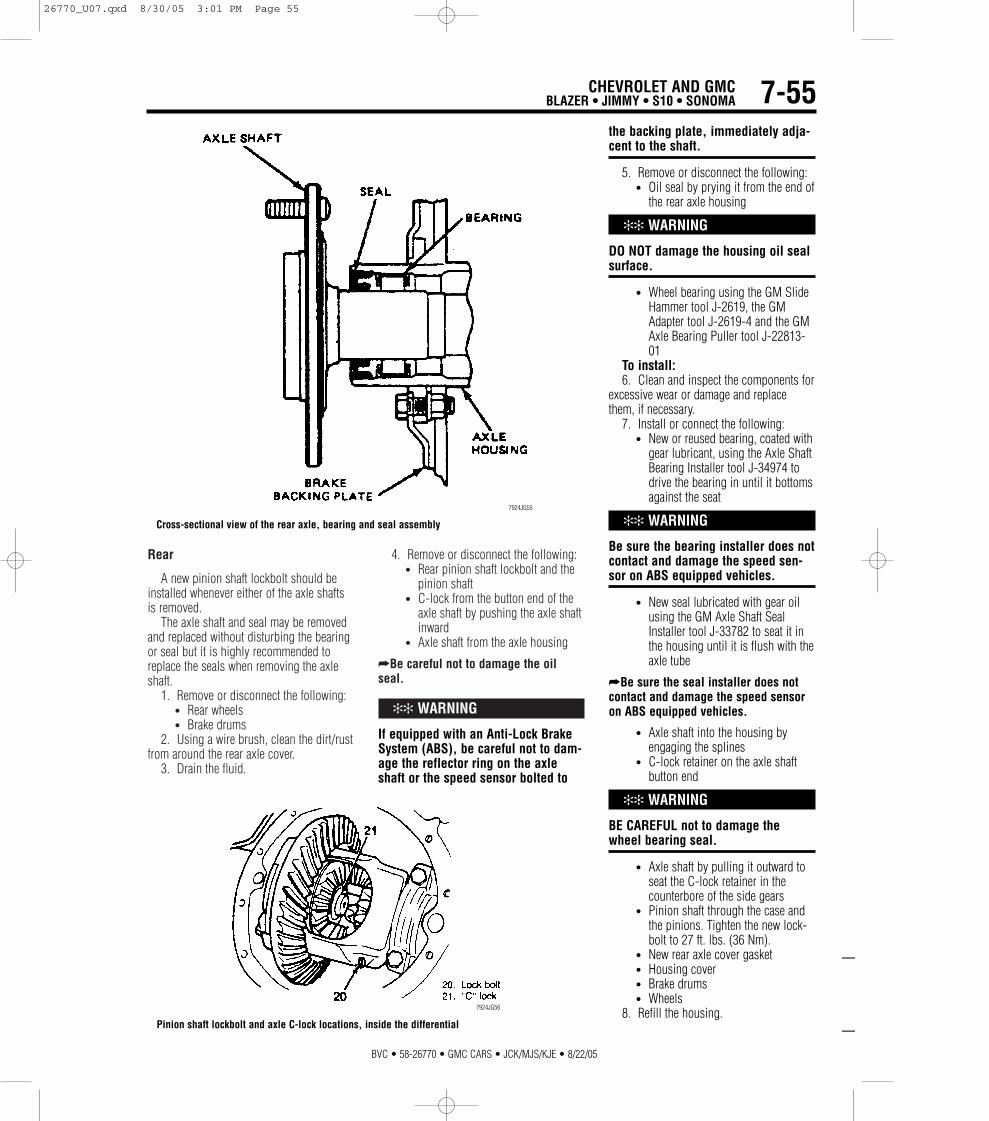
Rear
A new pinion shaft lockbolt should beinstalled whenever either of the axle shaftsis removed.
The axle shaft and seal may be removedand replaced without disturbing the bearingor seal but it is highly recommended toreplace the seals when removing the axleshaft.
1. Remove or disconnect the following:• Rear wheels• Brake drums
2. Using a wire brush, clean the dirt/rustfrom around the rear axle cover.
3. Drain the fluid.
4. Remove or disconnect the following:• Rear pinion shaft lockbolt and the
pinion shaft• C-lock from the button end of the
axle shaft by pushing the axle shaftinward
• Axle shaft from the axle housing
➦Be careful not to damage the oilseal.
✻✻ WARNING
If equipped with an Anti-Lock BrakeSystem (ABS), be careful not to dam-age the reflector ring on the axleshaft or the speed sensor bolted to
the backing plate, immediately adja-cent to the shaft.
5. Remove or disconnect the following:• Oil seal by prying it from the end of
the rear axle housing
✻✻ WARNING
DO NOT damage the housing oil sealsurface.
• Wheel bearing using the GM SlideHammer tool J-2619, the GMAdapter tool J-2619-4 and the GMAxle Bearing Puller tool J-22813-01
To install:6. Clean and inspect the components for
excessive wear or damage and replacethem, if necessary.
7. Install or connect the following:• New or reused bearing, coated with
gear lubricant, using the Axle ShaftBearing Installer tool J-34974 todrive the bearing in until it bottomsagainst the seat
✻✻ WARNING
Be sure the bearing installer does notcontact and damage the speed sen-sor on ABS equipped vehicles.
• New seal lubricated with gear oilusing the GM Axle Shaft SealInstaller tool J-33782 to seat it inthe housing until it is flush with theaxle tube
➦Be sure the seal installer does notcontact and damage the speed sensoron ABS equipped vehicles.
• Axle shaft into the housing byengaging the splines
• C-lock retainer on the axle shaftbutton end
✻✻ WARNING
BE CAREFUL not to damage thewheel bearing seal.
• Axle shaft by pulling it outward toseat the C-lock retainer in thecounterbore of the side gears
• Pinion shaft through the case andthe pinions. Tighten the new lock-bolt to 27 ft. lbs. (36 Nm).
• New rear axle cover gasket• Housing cover• Brake drums• Wheels
8. Refill the housing.
CHEVROLET AND GMCBLAZER • JIMMY • S10 • SONOMA
—
—
BVC • 58-26770 • GMC CARS • JCK/MJS/KJE • 8/22/05
7-55
Cross-sectional view of the rear axle, bearing and seal assembly
7924JG55
Pinion shaft lockbolt and axle C-lock locations, inside the differential
7924JG56
26770_U07.qxd 8/30/05 3:01 PM Page 55

BVC • 58-26770 • GMC CARS • JCK/MJS/KJE • 8/22/05
7-56 CHEVROLET AND GMCBLAZER • JIMMY • S10 • SONOMA
BRAKES
Brake Caliper
REMOVAL & INSTALLATION
Front
1. Remove or disconnect the following:• ²⁄₃ of the brake fluid from the mas-
ter cylinder reservoir• Tire and wheel assembly• Brake caliper fluid line, then plug it• Bolts retaining the caliper to the rotor• Caliper from the rotor• Disc brake pads from the caliper• Brake pad retaining clips from
inside the caliper
To install:2. Clean and lubricate the sleeves and
bushings with silicon grease.3. Install or connect the following:
• Pads in the caliper• Caliper in position over the rotor• Mounting bolts. Tighten to 38 ft.
lbs. (51 Nm).• Fluid lines to the caliper, if discon-
nected, and tighten to 40 ft. lbs. (54Nm)
• Wheel and tire assembly4. Refill the master cylinder to the cor-
rect level. Bleed the brake system if thefluid lines were disconnected from thecaliper.
Rear
1. Remove or disconnect the following:• Rear tires and wheels• Brake hose; and cap the line• Retainers from caliper and remove
caliper• Brake pads, if necessary
To install:2. Install or connect the following:
• Brake pads, if removed• Caliper over rotor, and onto mounts• Retainers, and tighten to 23 ft. lbs.
or (31 Nm)• Brake hose, and tighten to 33 ft.
lbs. (46 Nm)
Rear brake caliper
93026G44
26770_U07.qxd 8/30/05 3:01 PM Page 56

• Rear tires and wheels3. Refill the master cylinder to the cor-
rect level. Bleed the brake system if thefluid lines were disconnected from thecaliper.
Disc Brake Pads
REMOVAL & INSTALLATION
Front
1. Remove or disconnect the following:• ²⁄₃ of the brake fluid from the mas-
ter cylinder2. Place a C-clamp around the outer pad
and caliper; tighten the C-clamp until thepiston is fully compressed in the caliper.
• Remove top caliper retainer, androtate caliper away from rotor
• Inboard pad and retaining springfrom the caliper
• Outboard pad from the caliper• Sleeves and bushings
To install:3. Clean and lubricate the sleeves and
bushing with silicone lubricant and installthem in the caliper.
4. Install or connect the following:• Retaining spring onto the inboard
pad• Inboard pad in the caliper• Outboard pad into the caliper• Caliper in position over the rotor• Caliper mounting bolts. Bend the
tabs, on the outboard brake pad,over the caliper.
• Wheel and tire assemblies5. Refill the master cylinder and pump
pedal to attain full brake pedal before Road-testing the vehicle.
Rear
1. Remove or disconnect the following:• ²⁄₃ of the brake fluid from the mas-
ter cylinder• Wheels
2. Place a C-clamp around the outer padand caliper; tighten the C-clamp until thepiston is fully compressed in the caliper.
• Top caliper retainer, and rotatecaliper away from rotor
• Inboard pad and retaining springfrom the caliper
• Outboard pad from the caliperTo install:3. Clean and lubricate the sleeves and
bushing with silicone lubricant and installthem in the caliper.
4. Install or connect the following:• Retaining spring onto the inboard
pad• Inboard pad in the caliper• Outboard pad into the caliper• Caliper in position over the rotor• Caliper mounting bolts• Wheel and tire assemblies
5. Refill the master cylinder and pumppedal to attain full brake pedal before Road-testing the vehicle.
Brake Drums
REMOVAL AND INSTALLATION
1. Remove or disconnect the following:• Wheel and tire assembly• Brake drum. If the drum will not
pull of the axle, use a rubber malletand tap it around the edge.
To install:1. Install or connect the following:
• Drum on the axle• Wheel and tire assembly• Refill the master cylinder and pump
pedal to attain full brake pedalbefore road-testing the vehicle.
Brake Shoes
REMOVAL AND INSTALLATION
1. Remove or disconnect the following:• Wheel and tire assembly• Brake drum• Return springs from the brake
shoes• Shoe guide• Hold-down springs and pins• Actuator lever and pivot• Lever return spring• Actuator link• Parking brake strut and spring• Parking brake lever• Brake shoes and the adjuster
assemblyTo install:2. Lubricate the contact points on the
backing plate and the adjuster with lithiumgrease.
3. Install or connect the following:• Parking brake lever, adjusting
screw and spring assembly• Shoe assembly onto the backing
plate• Parking brake lever, strut and strut
spring• Actuator lever and lever pivot• Actuator link
CHEVROLET AND GMCBLAZER • JIMMY • S10 • SONOMA
—
—
BVC • 58-26770 • GMC CARS • JCK/MJS/KJE • 8/22/05
7-57
Compressing the caliper piston with a C-clamp
93026G47
Exploded view of the single piston front disc brake caliper
93026G48
26770_U07.qxd 8/30/05 3:01 PM Page 57

• Lever spring, the hold-down pinsand springs
• Shoe guide• Return springs• Brake drum in position
1. Adjust the brakes as follows:a. Remove the knockout area in the
backing plate, behind the adjusterassembly.
b. Ensure the parking brake system isadjusted properly with no tension on thecables or parking brake lever. The tops ofthe shoes should be firmly seated againstthe upper spring retaining anchor, if not asspecified, loosen the parking brake cables.
c. Install the drum and turn the brakeadjuster until the wheels can just beturned by hand.
d. Then, back the adjuster off 24notches. No brake drag should be feltafter 12 notches.
e. Install an adjusting hole plug in thebacking plate to prevent dirt and mois-ture from entering.
f. Readjust the parking brake cable asnecessary.2. Install the wheel and tire assemblies.3. Refill the master cylinder and pump
pedal to attain full brake pedal before Road-testing the vehicle.
BVC • 58-26770 • GMC CARS • JCK/MJS/KJE • 8/22/05
7-58 CHEVROLET AND GMCBLAZER • JIMMY • S10 • SONOMA
Exploded view of the drum brake components
93026G51
26770_U07.qxd 8/30/05 3:01 PM Page 58