chassis type a air conditioner optional parts
TRANSCRIPT

EXTE
RNAL
CO
NNEC
T KI
TU
TY-X
WZX
EXTE
RNAL
CO
NNEC
T KI
TU
TY-X
WZX
- (7) -
� Connection Method� CHASSIS TYPE A
En-1
AIR CONDITIONEROPTIONAL PARTSCommunication box kit
INSTALLATION MANUAL For authorized service personnel only.
PART NO. 9317807005
1. SAFETY PRECAUTIONS
WARNING This mark indicates procedures which, if improperly performed, might lead to the death or serious injury ofthe user.
• For the air conditioner to operate satisfactorily, install it as outlined in this installation manual.• Installation work must be performed in accordance with national wiring standards by authorized personnel only.• Do not turn on the power until all installation work is complete.• Discharge the static electricity before the operation.• Let the customer keep this installation manual because it is needed when the air conditioner or communication box kit is serviced
or moved.
CAUTION This mark indicates procedures which, if improperly performed, might possibly result in personal harm tothe user, or damage to property.
• Do not wire the communication box kit wire together with or parallel to the connection cables, transmission cables, remotecontroller cables, bus wire and power supply cables of the indoor and outdoor units. It may cause erroneous operation.
• Install the removed earth wire properly.• Do not touch the aluminum fin in the indoor unit.
2. ABOUT THE UNIT
2.1. Accessories• The following installation parts are supplied. Use them as required.
Name and shape Q'ty Description
Installationmanual
1
This manual
Control box
1
For connecting the wired remote control unit and externalconnect wire.
Name and shape Q'ty Description
Binder
1
For fixing the wiresfrom control box.
Screw1
For fixing the controlbox to the indoor unit.
Protectseal 2
For protecting the wires.
Contents1. SAFETY PRECAUTIONS ...................................................................................... 1
2. ABOUT THE UNIT2.1. Accessories ..................................................................................................... 1
3. INSTALLATION WORK3.1. Installing wired remote controller terminal /
external connect kit terminal (sold separately)................................................ 23.2. Installing communication box ......................................................................... 3
EXTE
RNAL
CO
NNEC
T KI
TU
TY-X
WZX
EXTE
RNAL
CO
NNEC
T KI
TU
TY-X
WZX
- (8) -
En-2
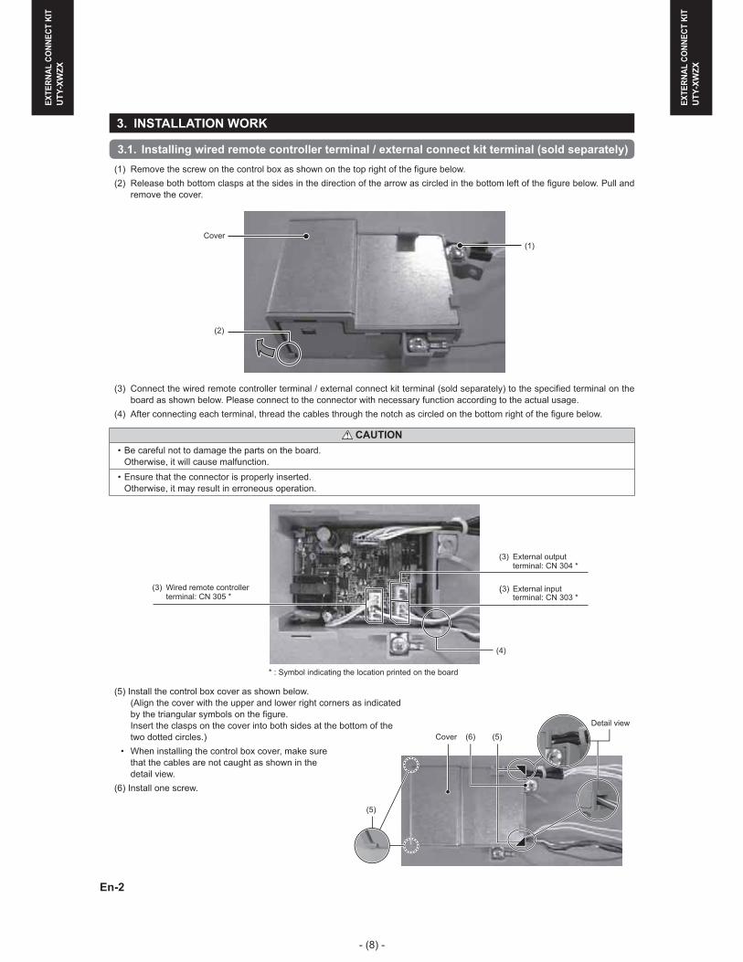
3. INSTALLATION WORK
3.1. Installing wired remote controller terminal / external connect kit terminal (sold separately)(1) Remove the screw on the control box as shown on the top right of the figure below.(2) Release both bottom clasps at the sides in the direction of the arrow as circled in the bottom left of the figure below. Pull and
remove the cover.
(2)
(1)Cover
(3) Connect the wired remote controller terminal / external connect kit terminal (sold separately) to the specified terminal on theboard as shown below. Please connect to the connector with necessary function according to the actual usage.
(4) After connecting each terminal, thread the cables through the notch as circled on the bottom right of the figure below.
CAUTION• Be careful not to damage the parts on the board.
Otherwise, it will cause malfunction.• Ensure that the connector is properly inserted.
Otherwise, it may result in erroneous operation.
(3) Wired remote controllerterminal: CN 305 *
* : Symbol indicating the location printed on the board
(3) External inputterminal: CN 303 *
(3) External outputterminal: CN 304 *
(4)
(5) Install the control box cover as shown below.(Align the cover with the upper and lower right corners as indicated by the triangular symbols on the figure.Insert the clasps on the cover into both sides at the bottom of thetwo dotted circles.)
• When installing the control box cover, make surethat the cables are not caught as shown in the detail view.
(6) Install one screw.
(5)
(5)(6)Cover
Detail view

EXTE
RNAL
CO
NNEC
T KI
TU
TY-X
WZX
EXTE
RNAL
CO
NNEC
T KI
TU
TY-X
WZX
- (9) -
En-3
3.2. Installing communication box
3.2.1. Removing intake grille (1) Open the intake grille until it is horizontal to the ground.(2) Support the intake grille with one hand and pull the knob on both sides of the unit towards you to unlock.
Mounting shaft
Intake grille
Mounting shaft
KnobKnob
(3) Lift and remove the intake grille.
3.2.2. Removing front panel (1) Lift the bottom of the front panel towards you and remove the wall hook bracket from the main unit.
• While pressing the “� mark” at the bottom of the front panel, lift the front panel towards you.
Front panel
(2) Remove the wire cover. (1 screw)(3) Remove the base screws (x3).
Wire cover
(4) While lifting the top of the front panel, pull it towards you and remove the front panel from the base.
CAUTION• Be careful when removing the front panel.
You may hurt yourself if the front panel drops.
Base
Front panel

EXTE
RNAL
CO
NNEC
T KI
TU
TY-X
WZX
EXTE
RNAL
CO
NNEC
T KI
TU
TY-X
WZX
- (10) -
En-4
3.2.3. Removing control box(1) Remove the screws (x3). (Use the same screws when installing.)(2) Pull the control box cover towards you and remove.
(1) (2)
(1)
(1)
(3) Remove the connectors (x4).• Remove and pull off the lock at the side of the connector insertion part.
CAUTION• Be careful not to damage the parts on the board.
Otherwise, it will cause malfunction.
Connector number: CN 3
Connector number: CN 4
Connector number: CN 5
Connector number: CN 7
* : Symbol indicating the location printed on the board

EXTE
RNAL
CO
NNEC
T KI
TU
TY-X
WZX
EXTE
RNAL
CO
NNEC
T KI
TU
TY-X
WZX
- (11) -
En-5
(4) Remove the protect seal (2 locations) that secures the wires to the fixtures.(5) Remove the wires from the three fixtures. (See the figure below)
• Leave the thick green wire in fixture C and remove the rest of the wires.
CAUTION• Do not pull the wires forcibly.
You may damage them.
Fixture A
Before After
Fixture B
Fixture C
Fixture C
(6) While pulling the control box towards you, remove in the right direction.• Do not remove the thermistor.• Do not damage the terminals on the removed wires. (See the figure below)
Thermistor
Control box
Terminals
Control box
(6)

EXTE
RNAL
CO
NNEC
T KI
TU
TY-X
WZX
EXTE
RNAL
CO
NNEC
T KI
TU
TY-X
WZX
- (12) -
En-6
3.2.4. Installing communication box (1) Install the communication box on the main unit and secure it with the provided screw at the location shown below.
• As shown in View A (detail view), hitch the clasp of the communication box onto the rib of the motor cover and secure with ascrew.
View A (Detail view)
Screw
Motor cover
View A (Detail view) Clasp
Rib
(2) Use the hole on the motor cover and secure the wire from the communication box with the provided binder.(See the figure below)
Binder
Cut away the tip of the binder.
Hole

EXTE
RNAL
CO
NNEC
T KI
TU
TY-X
WZX
EXTE
RNAL
CO
NNEC
T KI
TU
TY-X
WZX
- (13) -
En-7
3.2.5. Installing control box(1) Set the control box toward the bottom so that it touches the motor cover from the right.
• The installation method of the control box is different for eachdestination country. (See figure below)(When installing, reuse the screw that was removed in3.2.3. Removing control box.)
Insert the protruding part of the main unit on the fixture(1 location) into the control box.
Control box
For STANDARD MODEL and MULTI-SPLIT MODEL(2) Secure the control box with a screw.
(Use a long screw.)
(3)
(2)
For UL MODEL(2) Secure the control box.
When securing the box, use a long screw to fasten ittogether with the earth wire of the conduit holder.
(3)
(2)
(3) Fasten the earth wires of the heat exchanger together as shown in the left figure above.(Use a short screw here.)
(4) Hitch the wires onto the fixtures as shown in the oval circles below. Then connect the connectors in the squares to theterminals respectively.(Each terminal should form a pair with a connector.)
CAUTION• Ensure that the connector is properly inserted.
Otherwise, it may result in erroneous operation.• Be careful not to damage the parts on the board.
Otherwise, it will cause malfunction.
For STANDARD MODEL and MULTI-SPLIT MODEL(5)
For UL MODEL(5)

EXTE
RNAL
CO
NNEC
T KI
TU
TY-X
WZX
EXTE
RNAL
CO
NNEC
T KI
TU
TY-X
WZX
- (14) -
En-8
(5) Fasten the earth wire (green) in the communication box together with the earth wire (green) on the board of the control boxas shown below and in the bottommost figure of the previous page.
For STANDARD MODEL
(5)
For UL MODEL and MULTI-SPLIT MODEL
(5)
(6) Install the cover of the control box onto the inner side of the rib as shown below.
CAUTION• Do not cut or tuck the wires with the electrical component box cover.
An electric shock may occur if the wires are damaged.
(7) Tighten with screws to prevent the cover of the control box from falling off.(When installing, reuse the short screw that was removed in 3.2.3. Removing control box.)
(7)
(6)
Rib

EXTE
RNAL
CO
NNEC
T KI
TU
TY-X
WZX
EXTE
RNAL
CO
NNEC
T KI
TU
TY-X
WZX
- (15) -
En-9
(8) Paste protect seals (2 locations) to prevent the wires from sticking out.
(8)
3.2.6. Installing front panel(1) Insert the front panel so that it covers the base from the bottom.
(Insert the 5 bottom inner clasps of the front panel into the 5 holes at the bottom front of the base.)
(2) Next, insert the top part of the front panel into the base with both hands.(Insert the 3 upper inner clasps of the front panel into the 3 holes at the upper front of the base.)
(3) There are 2 clasps in the center of the front panel. Push these clasps with both hands.
CAUTION• Do not cut or tuck the wires with the front panel.
An electric shock may occur if the wires are damaged.• Be careful when installing the front panel.
You may hurt yourself if the front panel drops.
Upper holes (3 locations)
Base
Front panel

EXTE
RNAL
CO
NNEC
T KI
TU
TY-X
WZX
EXTE
RNAL
CO
NNEC
T KI
TU
TY-X
WZX
- (16) -
En-10
(4) Tighten and secure the front panel to the base with screws. (3 locations)(5) Install the wire cover and tighten with screws. (1 location)
Wire cover
3.2.7. Installing intake grille(1) Hold the intake grille horizontally and insert the mounting shafts into the left and right bearings at the upper portion of the
front panel.(2) Press the left and right upper knobs until they stop to lock.
Mounting shaft Mounting shaft
Bearing
Bearing
Knob Knob
(3) Close the intake grille.
4.1. Checking main unit operation(1) Check the operation of the main unit.

EXTE
RNAL
CO
NNEC
T KI
TU
TY-X
WZX
EXTE
RNAL
CO
NNEC
T KI
TU
TY-X
WZX
- (17) -
� CHASSIS TYPE B1. CONNECT TO INDOOR UNIT
(1) Remove the front panel. (Refer to INSTALLATION MANUAL of the indoor unit.)
(2) Remove the control box cover and connect the remote controller connector to the control board as below drawings.
control box cover
screw
connector
display case
Remove screws then remove the control box cover and remove the display case and connector.
connect the wire
rib
hole
binder stopper
screw
binder external connect wire
EXTERNAL INPUT : CONNCET TO No.CN14
EXTERNAL OUTPUT : CONNCET TO No.CN16
(3) Fix the binder stopper with the screw and bind the wire with the binder.
(4) Install the control box cover and the front panel as before.

EXTE
RNAL
CO
NNEC
T KI
TU
TY-X
WZX
EXTE
RNAL
CO
NNEC
T KI
TU
TY-X
WZX
- (18) -
� CHASSIS TYPE C1. CONNECT TO INDOOR
(1) Remove the side panel L. (Refer to INSTALLATION MANUAL of the indoor unit.)
(2) Remove the control cover and connect the remote controller connector to the control board as below drawings.
control cover
EXTERNAL INPUT : CONNCET TO No.CN14
EXTERNAL OUTPUT : CONNCET TO No.CN16
Attach a wire clamper and fix a wire with a clamper.
(3) Fix the binder stopper with the screw and bind the wire with the binder.
(4) Install the control cover and the side panel as before.