chasing a moving target from a flying uav - · chasing a moving target from a flying uav celine...
TRANSCRIPT

Chasing a moving target from a flying UAV
Celine Teuliere, Laurent Eck, Eric Marchand
Abstract— This paper proposes a vision-based algorithm toautonomously track and chase a moving target with a small-size flying UAV. The challenging constraints associated with theUAV flight led us to consider a density-based representationof the object to track. The proposed approach to estimate thetarget’s position, orientation and scale, is built on a robust color-based tracker using a multi-part representation. This objecttracker can handle large displacements, occlusions and accountfor some image noise due to partial loss of wireless video link,thanks to the use of a particle filter. The information obtainedfrom the visual tracker is then used to control the positionand yaw angle of the UAV in order to chase the target. Ahierarchical control scheme is designed to achieve the trackingtask. Experiments on a quad-rotor UAV following a smallmoving car are provided to validate the proposed approach.
I. INTRODUCTION
The vision-based control of Unmanned Aerial Vehicles(UAVs) has become a very active field of research in thelast decade [21] [1] [20] [6] [11]. Vision indeed providesa cheap, passive and rich source of information, and low-weight cameras can be embedded even on small-size flyingUAVs. Until now, most of the efforts have been concentratedon developing vision-based control methods for autonomoustake off, landing, stabilization and navigation, in which thevisual information is usually obtained using a known modelof a target [20] or the environment [22], key images [6], ortexture points for motion estimation [21] [16] or optical flowcomputation [11].
In this paper we consider the specific task of chasing amoving object, in an unknown environment, and without anya priori model of the object (see figure 1). The reliability ofthe visual information is critical for the good realization ofthe vision-based control task. For autonomously performingsuch a task, one has to be able to robustly extract theobject location from images despite difficult constraints:large displacements, occlusions, image noise, illuminationand pose changes or image blurr.
Considerable work has already been done in visual track-ing to address the aforementioned challenges, starting withdesigning an adequate representation for the object to betracked. A simple and widely used way to describe anobject is the image template, which stores luminance or colorvalues, and their locations [9][15]. Describing how the objectlooks like pixel-wise, image templates can accurately recovera large range of motions. However, they are very sensitive
C. Teuliere and L. Eck are with CEA, LIST, Interactive RoboticsUnit, 18 route du Panorama, BP6, Fontenay aux Roses, F- 92265 [email protected]
E. Marchand is with Universite de Rennes 1, IRISA, INRIA, LagadicProject, Rennes, France [email protected]
This work was realized in the context of the French ANR national projectSCUAV (ANR Psirob SCUAV project ref ANR-06-ROBO-0007-02)
Fig. 1. Quad-rotor UAV tracking a small vehicle and internal view fromthe embedded camera.
to some modifications in the object appearance due to posechanges, lighting variations, blurr or occlusions.
Density-based descriptors such as color histograms rep-resent an attractive alternative for their low computationalcomplexity and robustness to appearance changes [5] [19]. Inthe challenging UAV application context, strong simplifyingassumptions are usually made in the vision algorithms. [2][24]. In [2] a color-based algorithm is used to track a fixedtarget and autonomously stabilize a UAV above it. Dueto hardware limitations their proposed tracking approachis simplified and assumes that the target is clearly visible,without handling occlusions nor the presence of distractorsof similar color.
In this paper, our objective is to provide a full vision-basedsystem, using a color-based tracking method to robustlylocalize a moving object through frames and control theUAV to chase it. To our knowledge, this has never beendone while considering potential loss due to occlusions,and estimating not only the position of the object but itsrotation and scale changes in the image, which will allowus to control the UAV’s attitude and yaw.
We consider a quad-rotor UAV (see figure 1 and 7)equipped with a camera attached to its airframe, point-ing downward, an inertial measurement unit (IMU), anda barometer. Except for the low level embedded attitudecontrol, the computations are deported to a ground station.The data are transmitted between the ground station andthe UAV through a radio transmission. Figure 2 gives anoverview of the proposed system.• The visual tracking system aims to provide an estimate
of the relative position and in-plane rotation between theUAV and the object. To achieve this in a robust way,a color-based representation is chosen and the trackingis performed in the particle filtering framework. Thetracking system is presented in section II.
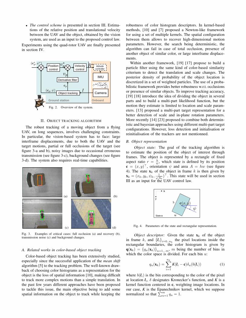
• The control scheme is presented in section III. Estima-tions of the relative position and translational velocitybetween the UAV and the object, obtained by the visionsystem, are used as an input to the proposed control law.
Experiments using the quad-rotor UAV are finally presentedin section IV.
OnboardGround station
Position control
Velocity control
IMU
Camera
Derivative filter
Object trackingI
R∗ Attitude controller
v∗p
vp
cp
(cp, ψ)
(c∗p, ψ∗)
Fig. 2. Overview of the system.
II. OBJECT TRACKING ALGORITHM
The robust tracking of a moving object from a flyingUAV, on long sequences, involves challenging constraints.In particular, the vision-based system has to face: largeinterframe displacements, due to both the UAV and thetarget motions, partial or full occlusions of the target (seefigure 3-a and b), noisy images due to occasional erroneoustransmission (see figure 3-c), background changes (see figure3-d). The system also requires real-time capabilities.
(a) (b)
(c) (d)
Fig. 3. Examples of critical cases: full occlusion (a) and recovery (b),transmission noise (c) and background changes.
A. Related works in color-based object tracking
Color-based object tracking has been extensively studied,especially since the successful application of the mean shiftalgorithm [5] to the tracking problem. The well-known draw-back of choosing color histograms as a representation for theobject is the loss of spatial information [10], making difficultto track more complex motions than a simple translation. Inthe past few years different approaches have been proposedto tackle this issue, the main objective being to add somespatial information on the object to track while keeping the
robustness of color histogram descriptors. In kernel-basedmethods, [10] and [7] proposed a Newton-like frameworkfor using a set of multiple kernels. The spatial configurationbetween them allows to recover high-dimensional motionparameters. However, the search being deterministic, thealgorithm can fail in case of total occlusion, presence ofanother object of similar color, or large interframe displace-ments.
Within another framework, [19] [17] propose to build aparticle filter using the same kind of color-based similaritycriterium to detect the translation and scale changes. Theposterior density of probability of the object location isdiscretized in a set of weighted particles. The use of a proba-bilistic framework provides better robustness w.r.t. occlusionsor presence of similar objects. To improve tracking accuracy,[19] [18] introduce the idea of dividing the object in severalparts and to build a multi-part likelihood function, but themotion they estimate is limited to location and scale param-eters. [13] proposed a multi-part target representation for abetter detection of scale and in-plane rotation parameters.More recently [14] [23] proposed to combine both determin-istic and bayesian approaches using different multi-part targetconfigurations. However, loss detection and initialisation orreinitialisation of the trackers are not mentionned.
B. Object representation
Object state: The goal of the tracking algorithm isto estimate the position of the object of interest throughframes. The object is represented by a rectangle of fixedaspect ratio r = h
w , which state is defined by its positionc = (x, y)>, orientation ψ and area A = hw (see figure4). The state xk of the object in frame k is then given byxk = (xk, yk, ψk,
1√Ak
)>. This state will be used in sectionIII as an input for the UAV control law.
State x
x
y
c(x, y)
ψ
h
w
Fig. 4. Parameters of the state and rectangular representation.
Object descriptor: Given the state xk of the objectin frame k, and lii=0..nk
the pixel locations inside therectangular boundaries, the color histogram is given byq(xk) = qu(xk)u=1...m, m being the number of bins inwhich the color space is divided. For each bin u:
qu(xk) =nk∑i=1
K(li − c)δu(b(li)) (1)
where b(li) is the bin corresponding to the color of the pixelat location li, δ designates Kronecker’s function, and K is akernel function centered in c, weighting image locations. Inour case, K is the Epanechnikov kernel, which we supposenormalized so that
∑mu=1 qu = 1.
Let q∗ = q∗uu=1...m denote the reference histogram, de-termined in the tracking initialisation step. Then, the trackingprocess aims to find in each frame k, the candidate statexk which histogram q(xk) is the “closest” to the referencehistogram q∗. To achieve this, a correlation criterion in thehistogram space is provided by Bhattacharyya coefficient:
ρ(xk) = ρ(q∗,q(xk)) =m∑u=1
√q∗uqu(xk). (2)
A candidate state xk for the object in frame k is thencompared to the reference object using the Bhattacharyyadistance:
d(xk) = d(q∗,q(xk)) =√
1− ρ(xk). (3)
Multi-kernel representation: To improve the sensitivityof the object descriptor to different motions we use a genericmulti-kernel representation. A set of identical kernels are po-sitionned in the rectangular object.Weighting pixels locationswith those kernels thus gives them a different importanceaccording to their position in the object.
Formally, a state xk is associated to nh histogramsqj(xk)j=1..nh
computed with the kernels Kj(l− cj). Thedistances dj(xk) = d(q∗j ,qj(xk)) are defined as in (3):
dm(xk) =1
nh
nh∑j=1
dj(xk) (4)
C. Tracking process
For the tracking to be robust to short occlusions of the ob-ject or noise due to transmission errors between the UAV andthe ground station, we use the particle filtering framework.The proposed tracking scheme is based on the well-knownCONDENSATION algorithm [12]. The main idea is torepresent the probability density function (p.d.f) p(xk | z1:k)of the state xk at frame k, by a finite set (s(i)k , π
(i)k )i=1..N
of N samples, or particles, s(i)k associated with the weightsπ(i)k . Each particle s
(i)k represents a potential state for the
object and z1:k are the observations until frame k. For eachnew frame, the particles first evoluate according to a givendynamic model. Then, the likelihood of every particle ismeasured in the image and a weight is derived. The outputconsidered is the weighted mean of the resulting set ofparticles. The particle set is updated by performing a randomweighted draw among the particles. This resampling steppromotes the best particles by duplicating them, to avoiddegeneracy issues and keep a fair representation of the p.d.f.
Likelihood function: The likelihood function is derivedfrom the distance defined in equation (4). The spatial in-formation is yielded by computing nh histograms in the nhparts as in [19] [14] [23]. Formally, the likelihood of a statexk is then defined by:
p(zk | xk) ∝ exp(−λdm2(xk)) (5)
where λ is a constant parameter tuned empirically (a typicalvalue is λ = 20).
For initialisation, the particles are sampled on a Gaussiandistribution around the initial known position. The particles
are propagated in the evolution step by a simple constantvelocity model. The particle filtering output considered is theestimator of probability expectation: E [xk] =
∑Ni=1 π
(i)k s
(i)k .
The algorithm is summarized in figure 5.
Knowing the set of N particles s(i)k−1i=1..Nwith equal
weights 1N at step k − 1:
• Evolution of the particles according to a constantvelocity model, giving a new set of particles:s′k
(i)i=1..N .
• Update: Using the observation zk the weight ofeach predicted particle is computed according to(5). π(i)
k ∝ p(
zk | xk = s′
k
(i))
, with∑Ni=1 π
(i)k =
1.• Resampling by performing a random weighted
draw of N particles from(s
′
k
(i), π
(i)k )i=1..N
,
thus giving the new set:(s
(i)k , 1
N )i=1..N
.
Fig. 5. Color-based tracking with particle filtering.
D. Loss detection
In case of complete occlusions or temporary image losses(see figure 3-a and c) the distance measurement becomesirrelevant and the resampling step of the particule filterpromotes the best particules in a wrong way. In such asituation, it is better to rely only on the evolution model. Thetracker is considered to be lost when the minimal particle’sdistance dmin (4) is above a given threshold dlim. Fornow, this threshold is tuned empirically, and refined in thebeginning of the sequence, where we assume the object isnot yet occluded, by taking dlim = 1.3dmin. However itwould benefit from an automatic adaptation for sequenceswith large illumination changes.
When the object is declared to be lost, the particle filterswitches to a critical mode with no resampling step, untilone particle gets under the threshold and the filter goes backto normal. This process allows the tracker to handle shortocclusions or peaks of noise in the images. If the filter failsto recover, a reinitialisation procedure needs to be performed.This is discussed in the following section.
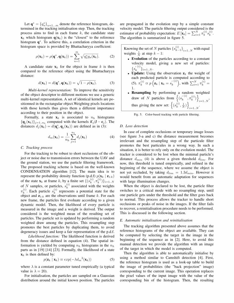
E. Automatic initialisation and reinitialisation
The tracking algorithm presented above assumes that thereference histograms of the object are available. They canbe computed by selecting the target in the image in thebeginning of the sequence as in [2]. Here, to avoid thismanual detection we provide the algorithm with an imageof the target in which the model is computed.
Then the algorithm is able to automatically initialise byusing a method similar to Camshift detection [4]. First,the reference histogram is used as a look-up table to buildthe image of probabilities (the ”back projection” image)corresponding to the current image. This operation replacesthe pixel values of the input image with the value of thecorresponding bin of the histogram. Then, the resulting
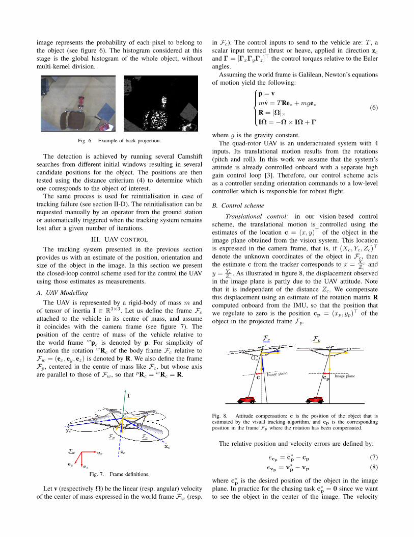
image represents the probability of each pixel to belong tothe object (see figure 6). The histogram considered at thisstage is the global histogram of the whole object, withoutmulti-kernel division.
Fig. 6. Example of back projection.
The detection is achieved by running several Camshiftsearches from different initial windows resulting in severalcandidate positions for the object. The positions are thentested using the distance criterium (4) to determine whichone corresponds to the object of interest.
The same process is used for reinitialisation in case oftracking failure (see section II-D). The reinitialisation can berequested manually by an operator from the ground stationor automatically triggered when the tracking system remainslost after a given number of iterations.
III. UAV CONTROL
The tracking system presented in the previous sectionprovides us with an estimate of the position, orientation andsize of the object in the image. In this section we presentthe closed-loop control scheme used for the control the UAVusing those estimates as measurements.
A. UAV ModellingThe UAV is represented by a rigid-body of mass m and
of tensor of inertia I ∈ R3×3. Let us define the frame Fcattached to the vehicle in its centre of mass, and assumeit coincides with the camera frame (see figure 7). Theposition of the centre of mass of the vehicle relative tothe world frame wpc is denoted by p. For simplicity ofnotation the rotation wRc of the body frame Fc relative toFw = (ex, ey, ez) is denoted by R. We also define the frameFp, centered in the centre of mass like Fc, but whose axisare parallel to those of Fw, so that pRc = wRc = R.
T
zc
Oc
ex
ezey
yc
Fc
Fw
Fp
xc
Fig. 7. Frame definitions.
Let v (respectively Ω) be the linear (resp. angular) velocityof the center of mass expressed in the world frame Fw (resp.
in Fc). The control inputs to send to the vehicle are: T , ascalar input termed thrust or heave, applied in direction zcand Γ = [ΓxΓyΓz]
> the control torques relative to the Eulerangles.
Assuming the world frame is Galilean, Newton’s equationsof motion yield the following:
p = vmv = TRez +mgezR = [Ω]×
IΩ = −Ω× IΩ + Γ
(6)
where g is the gravity constant.The quad-rotor UAV is an underactuated system with 4
inputs. Its translational motion results from the rotations(pitch and roll). In this work we assume that the system’sattitude is already controlled onboard with a separate highgain control loop [3]. Therefore, our control scheme actsas a controller sending orientation commands to a low-levelcontroller which is responsible for robust flight.
B. Control scheme
Translational control: in our vision-based controlscheme, the translational motion is controlled using theestimates of the location c = (x, y)> of the object in theimage plane obtained from the vision system. This locationis expressed in the camera frame, that is, if (Xc, Yc, Zc)
>
denote the unknown coordinates of the object in Fc, thenthe estimate c from the tracker corresponds to x = Xc
Zcand
y = Yc
Zc. As illustrated in figure 8, the displacement observed
in the image plane is partly due to the UAV attitude. Notethat it is independant of the distance Zc. We compensatethis displacement using an estimate of the rotation matrix Rcomputed onboard from the IMU, so that the position thatwe regulate to zero is the position cp = (xp, yp)
> of theobject in the projected frame Fp.
Fc
c
Fp
Oc
cpImage plan
eImage plane
Fig. 8. Attitude compensation: c is the position of the object that isestimated by the visual tracking algorithm, and cp is the correspondingposition in the frame Fp where the rotation has been compensated.
The relative position and velocity errors are defined by:
ecp = c∗p − cp (7)evp = v∗p − vp (8)
where c∗p is the desired position of the object in the imageplane. In practice for the chasing task c∗p = 0 since we wantto see the object in the center of the image. The velocity
vp is deduced from the differentiation of the position cp.
We use a hierarchical control. The inner-loop is a PIcontroller on the velocity, and the outer-loop a simple pro-portional control on the position:
vp∗ = −Kpecp (9)
The inner-loop on the velocity is required to ensure thestability of the system. It acts as a damping in the UAVcontrol.
Yaw control: the yaw angle ψ is controlled by using aproportional controller:
Ω∗z = −Kpψ(ψ∗ − ψ) (10)
where Kpψ denote the proportional gain. ψ∗ is the desiredyaw angle, that is the desired orientation of the object in theimage plane. It is set to zero in the experiments so that theUAV follows the rotations of the car. The yaw velocity Ωz
is controlled onboard using gyrometers measurements.Altitude: although the vision system also provides an
estimate of the size of the object which can be taken asa depth measurement, we found that the velocity obtainedby its differentiation was too noisy to be used directlyin the altitude control. For the experiments the altitude iscontrolled onboard using the barometer measurements toremain constant.
IV. EXPERIMENTAL VALIDATION
This section presents the experiments conducted on thequad-rotor (X4-flyer) (figure 1). The UAV sends the imagesfrom its embedded camera to the ground station (PC) througha wireless analogical link at 2.4GHz. The data is processedon the ground station and the desired orientation and thrustare sent back to the quad-rotor vehicle. Onboard, the expo-nential stability of the orientation toward the desired one isensured by a ’high gain’ controller (running at 166Hz in theDSP) [8]. On the ground station, the overall system (visualtracking and control computation) runs with a framerate of20Hz. We tested the overall system on different sequenceswith a small colored car (figure 1). In all the experimentsthe RGB color space with 8×8×8 bins has been used. Theparticle filter runs with 200 particles.
A. Stabilization task
We first present a stabilization task performed while thetarget car was static, to validate the good behaviour of thecontrol scheme. Figure 9 shows the resulting position errorfor the stabilization task: cp = (Xp/Zp Yp/Zp)
>.
In this experiment the measured altitude Zp was less than2 meters, which means that the UAV was stabilized abovethe target with a maximal translation error of 10cm. Figure9 shows that the maximum orientation error in stabilizationis 3deg.
−60 −40 −20 0 20 40 60
−60
−40
−20
0
20
40
60
u (pix)
v (p
ix)
0 5 10 15 20 25−8
−6
−4
−2
0
2
4
6
8Yaw error
Time (s)
Yaw
err
or (
deg)
Fig. 9. Trajectory of the center of the car in the image (pixel coordinates)and orientation error for the stabilization task.
Chasing a moving target: In this section we describea longer sequence (about 10000 frames) in which the caris moving, with some turns and several complete occlusions(see figure 12). Figure 10 shows the trajectory of the car inthe image.
Since the car’s motion mainly occurs on the y axis, theposition error is larger on this axis (up to 30cm, whichremains very low).
−150 −100 −50 0 50 100 150
−100
−50
0
50
100
u (pix)
v (p
ix)
Fig. 10. Trajectory of the center of the car in the image (pixel coordinates)for the chasing task.
Figure 11 illustrates the yaw angle estimation and controlwith an example of turn.
Fig. 11. Example of turn: the tracking system properly estimates therotation and the UAV follows it to keep the object with the same orientationin the camera frame.
When a loss is detected, the estimate position is drawnin orange (figure 12-b). In the experiments, the occlusionsare successfully detected, and the particle filter goes onpredicting the car position with the constant velocity model,without resampling. When the car is detected again (theestimated position is drawn in green in the image frame),the particle filter goes back to its normal mode. Since
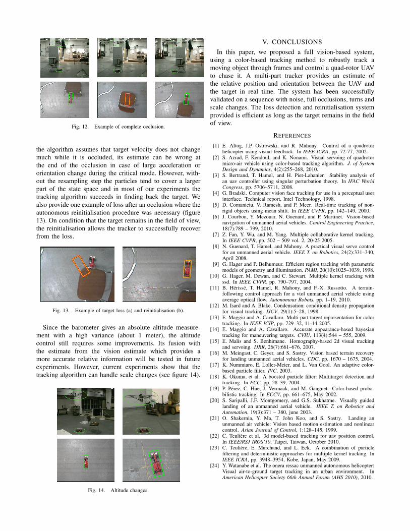
Fig. 12. Example of complete occlusion.
the algorithm assumes that target velocity does not changemuch while it is occluded, its estimate can be wrong atthe end of the occlusion in case of large acceleration ororientation change during the critical mode. However, with-out the resampling step the particles tend to cover a largerpart of the state space and in most of our experiments thetracking algorithm succeeds in finding back the target. Wealso provide one example of loss after an occlusion where theautonomous reinitialisation procedure was necessary (figure13). On condition that the target remains in the field of view,the reinitialisation allows the tracker to successfully recoverfrom the loss.
Fig. 13. Example of target loss (a) and reinitialisation (b).
Since the barometer gives an absolute altitude measure-ment with a high variance (about 1 meter), the altitudecontrol still requires some improvements. Its fusion withthe estimate from the vision estimate which provides amore accurate relative information will be tested in futureexperiments. However, current experiments show that thetracking algorithm can handle scale changes (see figure 14).
Fig. 14. Altitude changes.
V. CONCLUSIONSIn this paper, we proposed a full vision-based system,
using a color-based tracking method to robustly track amoving object through frames and control a quad-rotor UAVto chase it. A multi-part tracker provides an estimate ofthe relative position and orientation between the UAV andthe target in real time. The system has been successfullyvalidated on a sequence with noise, full occlusions, turns andscale changes. The loss detection and reinitialisation systemprovided is efficient as long as the target remains in the fieldof view.
REFERENCES
[1] E. Altug, J.P. Ostrowski, and R. Mahony. Control of a quadrotorhelicopter using visual feedback. In IEEE ICRA, pp. 72-77, 2002.
[2] S. Azrad, F. Kendoul, and K. Nonami. Visual servoing of quadrotormicro-air vehicle using color-based tracking algorithm. J. of SystemDesign and Dynamics, 4(2):255–268, 2010.
[3] S. Bertrand, T. Hamel, and H. Piet-Lahanier. Stability analysis ofan uav controller using singular perturbation theory. In IFAC WorldCongress, pp. 5706–5711, 2008.
[4] G. Bradski. Computer vision face tracking for use in a perceptual userinterface. Technical report, Intel Technology, 1998.
[5] D. Comaniciu, V. Ramesh, and P. Meer. Real-time tracking of non-rigid objects using mean shift. In IEEE CVPR, pp. 142–149, 2000.
[6] J. Courbon, Y. Mezouar, N. Guenard, and P. Martinet. Vision-basednavigation of unmanned aerial vehicles. Control Engineering Practice,18(7):789 – 799, 2010.
[7] Z. Fan, Y. Wu, and M. Yang. Multiple collaborative kernel tracking.In IEEE CVPR, pp. 502 – 509 vol. 2, 20-25 2005.
[8] N. Guenard, T. Hamel, and Mahony. A practical visual servo controlfor an unmanned aerial vehicle. IEEE T. on Robotics, 24(2):331–340,April 2008.
[9] G. Hager and P. Belhumeur. Efficient region tracking with parametricmodels of geometry and illumination. PAMI, 20(10):1025–1039, 1998.
[10] G. Hager, M. Dewan, and C. Stewart. Multiple kernel tracking withssd. In IEEE CVPR, pp. 790–797, 2004.
[11] B. Herisse, T. Hamel, R. Mahony, and F.-X. Russotto. A terrain-following control approach for a vtol unmanned aerial vehicle usingaverage optical flow. Autonomous Robots, pp. 1–19, 2010.
[12] M. Isard and A. Blake. Condensation: conditional density propagationfor visual tracking. IJCV, 29(1):5–28, 1998.
[13] E. Maggio and A. Cavallaro. Multi-part target representation for colortracking. In IEEE ICIP, pp. 729–32, 11-14 2005.
[14] E. Maggio and A. Cavallaro. Accurate appearance-based bayesiantracking for maneuvering targets. CVIU, 113(4):544 – 555, 2009.
[15] E. Malis and S. Benhimane. Homography-based 2d visual trackingand servoing. IJRR, 26(7):661–676, 2007.
[16] M. Meingast, C. Geyer, and S. Sastry. Vision based terrain recoveryfor landing unmanned aerial vehicles. CDC, pp. 1670 – 1675, 2004.
[17] K. Nummiaro, E. Loller-Meier, and L. Van Gool. An adaptive color-based particle filter. IVC, 2003.
[18] K. Okuma, et al. A boosted particle filter: Multitarget detection andtracking. In ECC, pp. 28–39, 2004.
[19] P. Perez, C. Hue, J. Vermaak, and M. Gangnet. Color-based proba-bilistic tracking. In ECCV, pp. 661–675, May 2002.
[20] S. Saripalli, J.F. Montgomery, and G.S. Sukhatme. Visually guidedlanding of an unmanned aerial vehicle. IEEE T. on Robotics andAutomation, 19(3):371 – 380, june 2003.
[21] O. Shakernia, Y. Ma, T. John Koo, and S. Sastry. Landing anunmanned air vehicle: Vision based motion estimation and nonlinearcontrol. Asian Journal of Control, 1:128–145, 1999.
[22] C. Teuliere et al. 3d model-based tracking for uav position control.In IEEE/RSJ IROS’10, Taipei, Taiwan, October 2010.
[23] C. Teuliere, E. Marchand, and L. Eck. A combination of particlefiltering and deterministic approaches for multiple kernel tracking. InIEEE ICRA, pp. 3948–3954, Kobe, Japan, May 2009.
[24] Y. Watanabe et al. The onera ressac unmanned autonomous helicopter:Visual air-to-ground target tracking in an urban environment. InAmerican Helicopter Society 66th Annual Forum (AHS 2010), 2010.