charter oak park improvements - addendum no. 1generalservices.townofmanchester.org/bidupload/charter...
TRANSCRIPT

TOWN OF MANCHESTER
GENERAL SERVICES DEPARTMENT
494 MAIN STREET
P.O. BOX 191
MANCHESTER, CONNECTICUT 06045-0191
CHARTER OAK PARK IMPROVEMENTS
BID NO. 16/17-13
ADDENDUM NO. 1
1. Minor changes have been made to proposed water and sanitary sewer facilities. Changes are
depicted on enclosed revised plan sheets 14 through 18.
2. Changes to grading and surface restoration limits have been made to the southwest corner of
the park entrance on property of #114 Charter Oak Street (part of Alternate Bid No. 1). The
removal of an existing stone retaining wall (paid under the item “Remove Miscellaneous
Concrete”) has been added. Changes are depicted on enclosed revised plan sheets 9 and 10.
3. The background for plan sheets 8, 11 and 12 has been updated to reflect the above changes
and revised plan sheets are enclosed for conformity.
4. The following changes have been made to the Bid Proposal:
a) Quantity changes have been made on Item Nos. 7, 12, 13, 14, 32, 41, 75, 79, 80 & 83.
b) Item No. 62A – 6” Gate Valve has been added to the Contract.
c) Item No. 74 – Hydrant Assembly with Tapping Sleeve and Valve has been deleted
from the Contract.
d) Item 81 has been changed from 48” Inside Drop Sanitary Manhole (0’-10’ Deep) to
48” Sanitary Manhole (10’-15’ Deep).
e) Item 82 has been changed from 48” Inside Drop Manhole (10’-15’ Deep) to 48”
Outside Drop Sanitary Manhole.
Revised Bid Proposal Sheets are enclosed.
5. Add the following special provisions to Item No. 100 “Modify Traffic Signal”:
a) Section 1.05 Control of Work
b) Section 1.06 Control of Materials
c) Section 1.07 Legal Responsibilities
d) Section 1.08 Prosecution and Progress
e) Section 10.00 General Clauses for Highway Illumination and Traffic Signal Projects\
f) Notice to Contractor – Recent Revisions
Replace the pedestrian signal special provision within Item No. 100 “Modify Traffic Signal”.
Revised “Modify Traffic Signal” specification is enclosed.

6. Replace the Water Main specification with the enclosed Water Main specification
(information on exposed ductile iron pipe, valves and fittings for Item No. 72 Pump Station
Retrofit added to Materials Section).
7. Replace the Hydrant Assembly specification with the enclosed Hydrant Assemble
specification (information on Item No. 73 Post Hydrant Assembly added to Materials
Section).
8. Add the enclosed CTDOT Standard Drawing “Trench Detail for State Roads” to the
Contract.
9. Add the enclosed Detail Sheet 23A to the Contract, which includes details for “Post Hydrant
Assembly”, “Pump Station Retrofit”, “Outside Drop Sanitary Manhole” and “Doghouse
Manhole”.
Enclosures: Revised “Water Main” specification
Revised “Hydrant Assembly” specification
Revised “Modify Traffic Signal” specification
Revised Bid Proposal
Revised Plan Sheets 1,8,9,10,11,12,14,15,16,17 and 18
New Plan Sheet 23A – Details
New CTDOT Standard Drawing “Trench Detail for State Roads”
August 1, 2016

WATER MAIN
TECHNICAL SPECIFICATIONS
WATER MAIN
TS-136
DESCRIPTION
“Water Main” of the size and type specified shall consist of the furnishing and installation water
pipe; and disinfection, flushing and testing of all ductile iron water pipe, fittings, valves, joint
restraint and other appurtenances as indicated on the Plans or directed by the Engineer.
Placement and compaction of backfill, filter fabric, bedding material, trench support systems,
abandonment of existing water mains, valves, blow-offs, and salvage of indicated items shall
also be included as part of this item. Existing water mains located within the excavation limits of
new main will not be measured separately for payment, but shall be considered as included in the
unit price bid for the new water main.
Fittings, valves and joint restraints of the size and type specified shall consist of furnishing and
installing these appurtenances where shown on the plans or as directed by the Engineer.
“Cut and Cap Water Main” shall include excavation; cutting and capping of existing pipe to
remain in service; and backfilling where shown on the plans or as directed by the Engineer.
“Pump Station Retrofit” includes the connection of proposed 8” water main and 1” copper
sampling line to existing piping within an existing building where shown on the Plans.
Refer to the General Conditions elsewhere in these specifications for licensing requirements for
any person involved in the installation of a water main and/or appurtenances.
MATERIALS
Unless otherwise specified by the Engineer, the pipe, fittings, valves and appurtenances to be
utilized in this work shall be new and unused, shall be of the types and materials specified herein
and shall meet the requirements specified herein. All material found during the progress of the
work to have cracks, flaws or other defects will be rejected by the Engineer. All defective
materials shall be promptly removed from the work site and replaced at no additional expense to
the Town.
Ductile Iron Pipe: Ductile iron pipe shall meet the requirements of the latest revision of
AWWA C151 (ANSI A21.51). Joints shall be “Tyton Joint” or “Fastite
Joint” design, rubber gasket push-on type manufactured in accordance
with the latest revision of AWWA C111 (ANSI A21.11). Pipe shall be
supplied with the standard exterior bituminous coating of either coal tar or
asphalt base approximately one mil thick. The interior shall be double
cement lined in accordance with the latest revision of AWWA C104
(ANSI A21.4), and pipe shall be of thickness Class 52 unless otherwise
indicated. Pipe shall be manufactured by Griffin, U.S. Pipe, McWane
Ductile, American or approved equal.

WATER MAIN
TECHNICAL SPECIFICATIONS
WATER MAIN
TS-137
Exposed DIP: Ductile iron pipe for exposed piping shall be thickness Class 53 flanged
pipe with ductile iron flanges meeting the requirements of AWWA/ANSI
C115/A21.15. The interior shall be cement lined in accordance with the
latest revisions of AWWA/ANSI C104/A21.4. Exterior of all exposed
piping shall be prime-coated and finish painted in accordance with the
requirements of these Specifications. Joints shall be flanged joints
conforming to AWWA C110 with a rated pressure of 250 PSI. Gaskets for
all flanged joints shall be of the ring type, 1/8-inch thick, full face, made
of natural or synthetic rubber, meeting the pipe manufacturer’s
requirements and AWWA C111. All bolts and nuts for flanged joints shall
conform to ANSI B.18.2.1 and ANSI B18.2.2 respectively, made of low
carbon steel conforming to ASTM A-307, Grade B. Pipe shall be
manufactured by Clow, Griffin, U.S. Pipe, Atlantic States, or approved
equal.
Joint Restraint: Restrained bell and spigot push on joints for ductile iron pipe shall meet
the requirements of the latest revision of AWWA C151 (ANSI A21.51).
Each restrained bell and spigot joint shall be achieved using a single
rubber FIELD LOK 350 gasket, a Series 1700 Megalug push on pipe bell
restraint harness as manufactured by Ebaa Iron, Inc., Eastland, Texas, a
Fast-Grip Gasket, or approved equal, manufactured in accordance with the
latest revision of AWWA C111 (ANSI A21.11). The bell and spigot push
on joint restraint provided shall be sufficient to restrain working pressures
of 350 psi.
Mechanical joint thrust restraining glands, for valves and fittings, shall be
the Megalug Series 1100, manufactured by Ebaa Iron, Eastland, Texas,
Ford series 1400, or approved equal.
Tiebolts, tiebolt nuts, rod couplings, threaded rods and rod nuts, retainer
clamps, and round flat washers may be used for restrained joints and shall
be steel meeting the requirements of ASTM A 36-77a. These components
shall be similar or equal to the following figure numbers manufactured by
Star National Products.
ITEM STAR FIGURE
Tiebolt 7, 7-5, or SST 7
Tiebolt and Rod Nut 8
Rod Coupling 10
Retainer Clamp 11
Threaded Rod 12
Round Flat Washer 17
Gate Valves: All gate valves shall be resilient wedge gate valves and shall meet the
requirements of AWWA C509 of latest revision. Valves shall have non-

WATER MAIN
TECHNICAL SPECIFICATIONS
WATER MAIN
TS-138
rising stems, mechanical joint ends meeting the requirements of AWWA
C111 of latest revision and have O-ring stem seals. Each valve shall be
supplied with two (2) sets of mechanical joint retainer glands. Valves shall
be wrench-operated and rated at a minimum working pressure of 200 psi.
Valves shall be right opening (clockwise) or left opening
(counterclockwise) as indicated on the plans or as directed by the
Engineer, which is dependent on where they are located in Town.
Wedge shall be encapsulated in molded rubber. Valve shall be coated
with a fusion bonded epoxy-resin both inside and outside. Coating shall be
a minimum of 10 mils thick and be in full compliance with (i.e. meet or
exceed) all requirements of the latest revision of AWWA C550.
Resilient wedge gate valves shall be only those models and manufacturers
listed below.
Manufacturer Model
American Flow Control Series 2500
AVK Series 25
Clow F-6100
M & H Style 4067
Mueller A-2362 (Ductile Iron Body)
U.S. Pipe A-USPO-23
Exposed Gate Valves: Gate valves shall be resilient seated wedge style, iron body, bronze
mounted, and shall meet the requirements of AWWA C509 of latest
revision. Valves shall have rising stems, flanged ends conforming to
B16.1, Class 125. Valves shall be equipped with hand wheels. Valves
shall be left-opening (clockwise) and shall indicate the direction of
operation. Valves shall be rated for 250 PSI working pressure. Valve sizes
shall be as shown on the drawings. Valves shall have a fusion bonded
epoxy coating inside and outside meeting the requirements of AWWA
C550.
Wedge shall be encapsulated in molded rubber.
Valves shall have manufacturer’s name and working pressure cast in
raised letters on valve body.
Each valve to be supplied shall have a stainless steel identification
nameplate stamped with the approved designation. Nameplate shall be
permanently fastened to valve body at the factory.

WATER MAIN
TECHNICAL SPECIFICATIONS
WATER MAIN
TS-139
Exposed Gate valves shall be UL listed, FM approved, NSF61 certified,
manufactured in North America and be from one of the following
manufacturers.
1. Mueller
2. AVK
3. American Flow Control
4. U.S. Pipe
5. M&H
6. Clow
Butterfly Valves: Valves shall be wrench operated, non-rising stem with O-ring stem seals
and have mechanical joints on both ends. Each valve shall be supplied
with two (2) sets of mechanical joint retainer glands. Valves shall meet or
exceed the requirements of the latest revision of AWWA C504. Valves
shall have epoxy coated cast iron bodies with mechanical joint ends
complying with the latest revisions of ANSI A21.11 (AWWA C111).
Valves shall be a minimum Class 150B and suitable for a maximum
nonshock shutoff pressure of 140 psi. The valves shall provide bubble-
tight shutoff at 150 psi when tested in accordance with AWWA C504.
Valve discs shall seat at an angle of 90 degrees to the axis of the pipe.
Valve seats shall be molded natural rubber. Rubber seats may be attached
to the body or the disc. If the rubber seat is attached to the disc, the seat
ring on the body shall be of stainless steel. The valve disc shall be of either
case Ni-Resist of cast iron Class 40 conforming to ASTM A48. Rubber
seats mounted on the disc shall be securely clamped to the disc. All
clamps, retaining rings, and their fasteners shall be Series 300 stainless
steel.
The valve shaft shall be Type 300 stainless steel or carbon steel with
stainless steel joints. The valve disc and shaft connection shall be by
means of mechanically secured taper pins extending through the disc and
shaft. Taper pins, lockwashers and nuts shall be 18-8 stainless steel. The
shaft seals shall be designed for the use of standard "O" -ring seals.
The manual operating mechanism shall be firmly fixed to the valve body
and shall be rated at 450 lb. The operator shall be permanently lubricated,
shall be totally enclosed with a cast iron case. The operator shall be
suitable for submersion. The operator shall have adjustable threaded
collars at each end of stroke. Valves shall be right opening (clockwise)
or left opening (counterclockwise) as indicated on the plans or as
directed by the Engineer, which is dependent on where they are
located in Town.

WATER MAIN
TECHNICAL SPECIFICATIONS
WATER MAIN
TS-140
Valves shall be only those models and manufacturers listed below.
Manufacturer Model
Mueller Lineseal III
M & H Style 450
Tapping Sleeve and Tapping sleeves shall consist of a full body two-piece ductile iron or cast
Valve TYPE I (CIP): iron sleeve/tee with mechanical joint ends on the run and a flanged end on
the branch. Each sleeve shall be supplied with two (2) sets of mechanical
joint retainer glands. Tapping valves shall be resilient wedge gate valves
meeting the requirements described below. The tapping valve shall have
one flanged end and one mechanical joint end.
Valves shall be wrench operated, non-rising stem with O-ring stem seals.
Each valve shall be supplied with one (1) set of type I-Mechanical Joint
Retainer Glands. Valves shall be right opening (clockwise) or left
opening (counterclockwise) as indicated on the plans or as directed by
the Engineer, which is dependent on where they are located in Town.
Wedge shall be encapsulated in molded rubber.
Valve shall be coated with a fusion bonded epoxy-resin both inside and
outside. Coating shall be a minimum of 10 mils thick and be in full
compliance with (i.e. meet or exceed) all requirements of the latest
revision of AWWA C550.
Valves and joints shall be in full compliance with (i.e. meet or exceed) all
requirements of the latest revision of AWWA C509 and AWWA C111
respectively.
Valves shall be only those models and manufacturers listed below.
Manufacturer Model
American Flow Control Series 2500
AVK Series 25
Clow F-6114
M & H Style 4067
Mueller A-2362 (Ductile Iron Body)
U.S. Pipe A-USPO-23
Tapping sleeves shall be manufactured by U.S. Pipe, Mueller, American
Flow Control or approved equal.
Tapping Sleeve and Tapping sleeve shall consist of a stainless steel body with either a stainless
Valve TYPE II (DIP): steel or carbon steel integral mechanical joint outlet flange. Gasket shall
WATER MAIN
TECHNICAL SPECIFICATIONS
WATER MAIN
TS-141
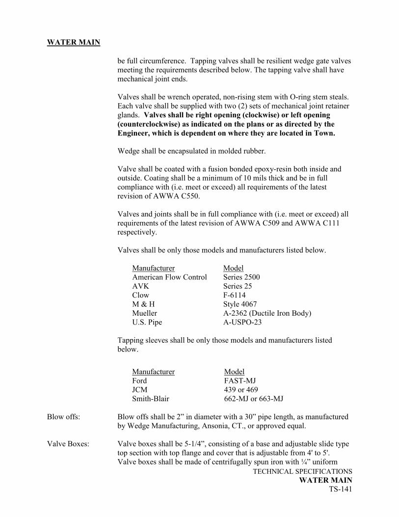
be full circumference. Tapping valves shall be resilient wedge gate valves
meeting the requirements described below. The tapping valve shall have
mechanical joint ends.
Valves shall be wrench operated, non-rising stem with O-ring stem steals.
Each valve shall be supplied with two (2) sets of mechanical joint retainer
glands. Valves shall be right opening (clockwise) or left opening
(counterclockwise) as indicated on the plans or as directed by the
Engineer, which is dependent on where they are located in Town.
Wedge shall be encapsulated in molded rubber.
Valve shall be coated with a fusion bonded epoxy-resin both inside and
outside. Coating shall be a minimum of 10 mils thick and be in full
compliance with (i.e. meet or exceed) all requirements of the latest
revision of AWWA C550.
Valves and joints shall be in full compliance with (i.e. meet or exceed) all
requirements of the latest revision of AWWA C509 and AWWA C111
respectively.
Valves shall be only those models and manufacturers listed below.
Manufacturer Model
American Flow Control Series 2500
AVK Series 25
Clow F-6114
M & H Style 4067
Mueller A-2362 (Ductile Iron Body)
U.S. Pipe A-USPO-23
Tapping sleeves shall be only those models and manufacturers listed
below.
Manufacturer
Model
Ford FAST-MJ
JCM 439 or 469
Smith-Blair 662-MJ or 663-MJ
Blow offs: Blow offs shall be 2” in diameter with a 30” pipe length, as manufactured
by Wedge Manufacturing, Ansonia, CT., or approved equal.
Valve Boxes: Valve boxes shall be 5-1/4”, consisting of a base and adjustable slide type
top section with top flange and cover that is adjustable from 4' to 5'.
Valve boxes shall be made of centrifugally spun iron with ¼” uniform

WATER MAIN
TECHNICAL SPECIFICATIONS
WATER MAIN
TS-142
wall thickness. Box cover shall have the word "WATER" cast on top.
Valve boxes shall be coated with heavy bituminous coating and be
manufactured in the United States or Canada by Water Quality Products,
Bibby Ste. Croix, Charlotte, Tyler, Bingham and Taylor, or approved
equal.
Fittings: Fittings, including mechanical joint plugs and caps, shall be ductile iron
meeting the requirements of AWWA C110 (ANSI A21.10) with
mechanical joints in conformance with AWWA C111 (ANSI A21.11).
Fittings shall have a minimum pressure rating of 350 psi and shall have an
inside lining of cement-mortar in accordance with AWWA C104 (ANSI
A21.4). Compact fittings meeting the requirements of AWWA C153
(ANSI A21.53) of latest revision may be used. Fittings shall have an
asphalt coating both inside and outside, and be manufactured in the United
States or Canada by Griffin, Tyler, U.S. Pipe, Sigma, Clow, Union or
approved equal.
Exposed Fittings: All exposed fittings shall be flanged joint ductile iron conforming to
AWWA C110 (ANSI A21.10). Gaskets for all fittings shall be natural or
synthetic rubber, 1/8-inch thick, full face. Bolts and nuts shall conform to
ANSI B18.2.1 and ANSI B18.2.2, respectively. Exposed bolts and buts
shall be ASTM A307, Grade B. Fittings shall have cement lined and seal
coated interior in accordance with AWWA C104 and a primed exterior.
Fittings shall be manufactured in North America by Griffin, Tyler, U.S.
Pipe, Sigma, Clow, Union or approved equal.
Flange adaptors shall be made of ASTM A536 Grade 65-45-12 ductile
iron. Drilling shall be done in accordance with ANSI B16.1, Class 125 for
ductile iron flanges. Flanges shall meet all test requirements of AWWA
C110/A21.10. A MJ type gasket shall be provided with the flange adaptors
for installation.
Pipe and fittings to be installed above ground shall receive a minimum of
one (1) coat of Koppers 654 Epoxy Primer, Tnemec 66-1211 Epoxoline
Primer, or equal, to a minimum four (4) mil DFT on the exterior surfaces.
Finish painting for all pipe and fittings shall be one coat of high build
polyamide epoxy, Tnemec Series 66 Epoxoline @ 3.0 mils dry or
approved equal. Finish color shall be light blue.
Sleeves: Sleeves for connecting new mains to existing mains shall be mechanical
joint solid sleeves with the mechanical joint ends restrained by the means
of retainer glands. Solid sleeves shall meet the requirements of the latest
revision of AWWA C110 (ANSI A21.10) and shall be Model F-1014 as

WATER MAIN
TECHNICAL SPECIFICATIONS
WATER MAIN
TS-143
manufactured by the Clow Corporation, Oak Brook, Illinois, or approved
equal.
Connecting sleeves for connecting new water mains to existing metal lined
cement mains (stovepipe) shall be Model 227 as manufactured by
Rockwell, Pittsburgh, PA or approved equal.
Pipe Markers: For exposed pipe, provide self-adhesive pipe markers to indicate direction
of flow as shown on the drawings and as specified herein. Markers shall
contain black arrows in a safety yellow background.
Pipe Supports: Pipe supports shall be provided for exposed ductile iron pipe. Provide
adequate pipe supports to prevent sag, vertical and lateral movement in a
manner which will prevent undue strain on any valve, fitting, pipe or piece
of equipment. Supports shall be of the saddle type with an adjustable
collar and an oversized base, suitable for ductile iron pipe and fittings.
Supports shall be factory fabricated units, complete with necessary bolts,
nuts, washers, plates etc., Contractor fabricated supports are not allowed.
Supports shall be made of ASTM A36 Steel and have a corrosion resistant
galvanized finish.
Supports shall be Standon Model S92 as manufactured by Material
Resources Inc., Hillsboro, OR. or approved equal.
Couplings: Couplings for connecting new main to oversized cast iron pipe shall be
Rockwell Model 441 Cast Transition Couplings, or approved equal.
These couplings shall be used only when oversized cast iron pipe is
encountered which does not allow the use of solid sleeves.
Concrete: Concrete for thrust blocks, pipe cradles, sealing abandoned pipe, etc., shall
conform to the requirements of the pertinent section of these
Specifications.
Polyethylene Wrap: Polyethylene wrap for fittings with poured concrete thrust blocks shall
meet the requirements for the latest revision of AWWA C105.
Pipe Insulation: Insulation boards for water main pipe shall be closed cell, extruded
polystyrene foam meeting ASTM C578, manufactured by Thermal Foams
Inc., Buffalo, NY., or 2” thick Cellular Glass Insulation meeting the
requirements of the latest revision of ASTM C552 with an aluminum
jacket. Insulation shall be Foamglas Cellular Glass manufactured by
Pittsburgh Corning, Pittsburgh, PA., or approved equal.
Bedding Material: Bedding material shall be as indicated on the Plans and shall meet the
requirements of Article M.08.01-21 for sand, Article M.02.01-1 for

WATER MAIN
TECHNICAL SPECIFICATIONS
WATER MAIN
TS-144
crushed stone, and Article M.02.01-2 (Grading “C”) of Form 816 for bank
run gravel.
Backfill: Backfill material above bedding material shall be suitable material from
the excavation which is free from large or frozen lumps of soil, wood or
other extraneous material or, if directed by the Engineer, shall be approved
backfill material meeting the requirements of Article M.02.06 (Grading
“B”) of Form 816.
Filter Fabric: Filter fabric shall be a non-woven fabric similar or equal to Mirafi 140 as
manufactured by Celanese Fibers Marketing Company, Bidim C22 as
manufactured by Monsanto Textiles Company or approved equal.
Warning Tape: Underground pipe warning (marking) tape shall be plastic and metallic-
coated to permit detection by a magnetic sensing device. The tape shall be
blue in color, not less than 3 inches in width, and shall have the words
"CAUTION - BURIED WATER MAIN BELOW" repeated along the
full length of the tape in letters not less than 1" high permanently fused
into the tape. Pipe marking tape shall be "Terra-Tape" detectable pipe
marking tape as manufactured by Reef Industries, Inc., Houston, Texas or
approved equal.
Steel Sheeting: Steel sheeting for trench stabilization, if required, shall conform to the
requirements of ASTM A328, ASTM A572 or ASTM A690 as
appropriate.
Pavement Markings: Pavement markings installed to replace disturbed markings shall be
painted, match the size and color of existing markings, and meet the
requirements of “Painted Pavement Markings” as defined in the pertinent
sections of these Specifications.
CONSTRUCTION DETAILS
General
Trench excavation and surface restoration shall conform to the requirements of the pertinent
section of these Specifications. Water mains shall only be installed in trench conditions;
embankment conditions will not be permitted.
Ductile iron pipe, fittings and valves shall be installed as detailed and directed, and in full
accordance with the latest revision of AWWA C600, manufacturer's recommendations, and
accepted best practice, with the below listed qualifications and clarifications. The methods
employed in performing the work, and all equipment, tools and machinery used in handling
material and executing any part of the work shall be subject to the approval of the Engineer
WATER MAIN
TECHNICAL SPECIFICATIONS
WATER MAIN
TS-145
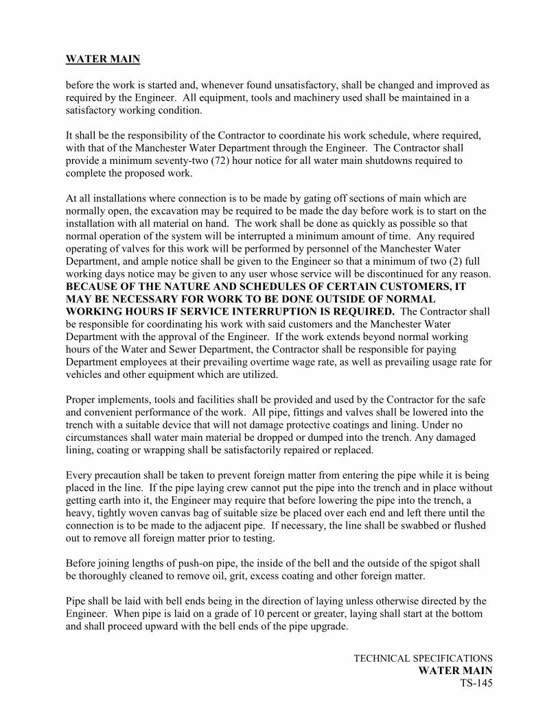
before the work is started and, whenever found unsatisfactory, shall be changed and improved as
required by the Engineer. All equipment, tools and machinery used shall be maintained in a
satisfactory working condition.
It shall be the responsibility of the Contractor to coordinate his work schedule, where required,
with that of the Manchester Water Department through the Engineer. The Contractor shall
provide a minimum seventy-two (72) hour notice for all water main shutdowns required to
complete the proposed work.
At all installations where connection is to be made by gating off sections of main which are
normally open, the excavation may be required to be made the day before work is to start on the
installation with all material on hand. The work shall be done as quickly as possible so that
normal operation of the system will be interrupted a minimum amount of time. Any required
operating of valves for this work will be performed by personnel of the Manchester Water
Department, and ample notice shall be given to the Engineer so that a minimum of two (2) full
working days notice may be given to any user whose service will be discontinued for any reason.
BECAUSE OF THE NATURE AND SCHEDULES OF CERTAIN CUSTOMERS, IT
MAY BE NECESSARY FOR WORK TO BE DONE OUTSIDE OF NORMAL
WORKING HOURS IF SERVICE INTERRUPTION IS REQUIRED. The Contractor shall
be responsible for coordinating his work with said customers and the Manchester Water
Department with the approval of the Engineer. If the work extends beyond normal working
hours of the Water and Sewer Department, the Contractor shall be responsible for paying
Department employees at their prevailing overtime wage rate, as well as prevailing usage rate for
vehicles and other equipment which are utilized.
Proper implements, tools and facilities shall be provided and used by the Contractor for the safe
and convenient performance of the work. All pipe, fittings and valves shall be lowered into the
trench with a suitable device that will not damage protective coatings and lining. Under no
circumstances shall water main material be dropped or dumped into the trench. Any damaged
lining, coating or wrapping shall be satisfactorily repaired or replaced.
Every precaution shall be taken to prevent foreign matter from entering the pipe while it is being
placed in the line. If the pipe laying crew cannot put the pipe into the trench and in place without
getting earth into it, the Engineer may require that before lowering the pipe into the trench, a
heavy, tightly woven canvas bag of suitable size be placed over each end and left there until the
connection is to be made to the adjacent pipe. If necessary, the line shall be swabbed or flushed
out to remove all foreign matter prior to testing.
Before joining lengths of push-on pipe, the inside of the bell and the outside of the spigot shall
be thoroughly cleaned to remove oil, grit, excess coating and other foreign matter.
Pipe shall be laid with bell ends being in the direction of laying unless otherwise directed by the
Engineer. When pipe is laid on a grade of 10 percent or greater, laying shall start at the bottom
and shall proceed upward with the bell ends of the pipe upgrade.

WATER MAIN
TECHNICAL SPECIFICATIONS
WATER MAIN
TS-146
The cutting of pipe for inserting valves, fittings or closure pieces shall be done in a neat manner
without damage to the pipe or cement lining and so as to leave a smooth end at right angles to the
axis of the pipe.
The deflection at pipe joints to accommodate changes in horizontal or vertical alignment shall be
in accordance with the recommendations of the manufacturer. Where bends are called for on the
plans, a standard bend may be used with any additional deflection required accomplished by
deflecting joints on adjacent pipes.
Bends shall be used only at the locations shown on the plans or at other locations approved by
the Engineer.
Underground valves shall rest on concrete masonry units. Valve boxes shall not transmit shock
or stress to the valve and shall be centered and plumb over the wrench nut of the valve. The
valve box cover shall be flush with the surface of the finished pavement or such other level as
may be directed.
Valves set with a depth to operating nut greater than 6 feet shall be equipped with extension
stems providing an operating nut depth of 4.5 feet. Extension stems shall be installed such as to
preclude accidental disconnection from the valve, shall stand plumb and shall be supported at the
upper end with a centering device attached to the stem or valve box.
Water main installed with less than 4.5 feet of cover must be insulated unless approved otherwise
by the Engineer. Insulated water main must have 2.5 feet of minimum cover.
Water main shall be installed with a minimum 2 feet of clearance from existing structures unless
indicated otherwise on the plans or directed by the Engineer.
Care shall be taken not to excavate below the depths required to perform the Work. The
Contractor shall furnish and employ such trench boxes, steel plates, shores, braces, sheeting,
pumps, etc., as may be necessary for the protection of property, proper completion of the Work
and the safety of the public and employees of the Contractor and the Town. All bracing,
sheeting, etc., shall be removed when no longer required for the construction or safety of the
Work.
All excavated materials not required or unsuitable for backfill, (i.e., clay, silt, sand, muck, gravel,
hardpan, loose shale, loose stone in masses and boulders greater than 5” in diameter) shall be
removed and properly disposed of by the Contractor. Unsuitable soils that exhibit obvious
evidence of heavy contamination or have been identified as containing elevated concentrations of
contamination should be removed and stockpiled for characterization and possible off-site
disposal. If contaminated soils are stockpiled best management practices must be employed to
reduce human and environmental exposure to the stockpiled materials. Granular fill shall be
used to replace all unsuitable material.
WATER MAIN
TECHNICAL SPECIFICATIONS
WATER MAIN
TS-147
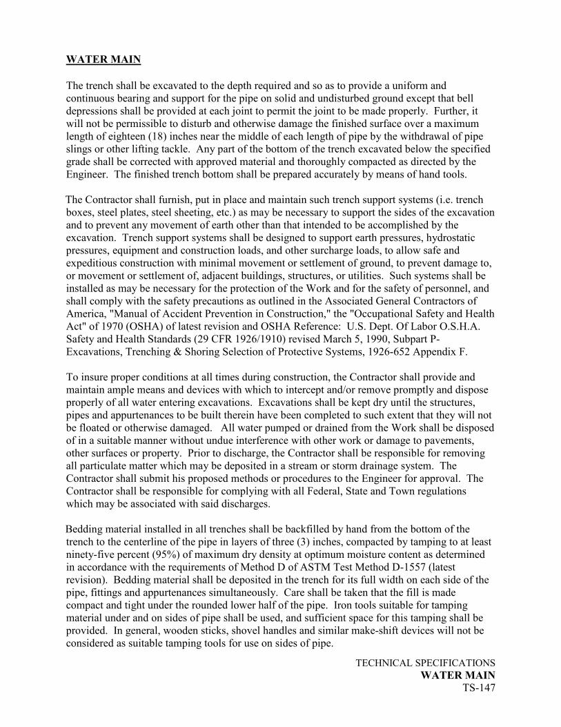
The trench shall be excavated to the depth required and so as to provide a uniform and
continuous bearing and support for the pipe on solid and undisturbed ground except that bell
depressions shall be provided at each joint to permit the joint to be made properly. Further, it
will not be permissible to disturb and otherwise damage the finished surface over a maximum
length of eighteen (18) inches near the middle of each length of pipe by the withdrawal of pipe
slings or other lifting tackle. Any part of the bottom of the trench excavated below the specified
grade shall be corrected with approved material and thoroughly compacted as directed by the
Engineer. The finished trench bottom shall be prepared accurately by means of hand tools.
The Contractor shall furnish, put in place and maintain such trench support systems (i.e. trench
boxes, steel plates, steel sheeting, etc.) as may be necessary to support the sides of the excavation
and to prevent any movement of earth other than that intended to be accomplished by the
excavation. Trench support systems shall be designed to support earth pressures, hydrostatic
pressures, equipment and construction loads, and other surcharge loads, to allow safe and
expeditious construction with minimal movement or settlement of ground, to prevent damage to,
or movement or settlement of, adjacent buildings, structures, or utilities. Such systems shall be
installed as may be necessary for the protection of the Work and for the safety of personnel, and
shall comply with the safety precautions as outlined in the Associated General Contractors of
America, "Manual of Accident Prevention in Construction," the "Occupational Safety and Health
Act" of 1970 (OSHA) of latest revision and OSHA Reference: U.S. Dept. Of Labor O.S.H.A.
Safety and Health Standards (29 CFR 1926/1910) revised March 5, 1990, Subpart P-
Excavations, Trenching & Shoring Selection of Protective Systems, 1926-652 Appendix F.
To insure proper conditions at all times during construction, the Contractor shall provide and
maintain ample means and devices with which to intercept and/or remove promptly and dispose
properly of all water entering excavations. Excavations shall be kept dry until the structures,
pipes and appurtenances to be built therein have been completed to such extent that they will not
be floated or otherwise damaged. All water pumped or drained from the Work shall be disposed
of in a suitable manner without undue interference with other work or damage to pavements,
other surfaces or property. Prior to discharge, the Contractor shall be responsible for removing
all particulate matter which may be deposited in a stream or storm drainage system. The
Contractor shall submit his proposed methods or procedures to the Engineer for approval. The
Contractor shall be responsible for complying with all Federal, State and Town regulations
which may be associated with said discharges.
Bedding material installed in all trenches shall be backfilled by hand from the bottom of the
trench to the centerline of the pipe in layers of three (3) inches, compacted by tamping to at least
ninety-five percent (95%) of maximum dry density at optimum moisture content as determined
in accordance with the requirements of Method D of ASTM Test Method D-1557 (latest
revision). Bedding material shall be deposited in the trench for its full width on each side of the
pipe, fittings and appurtenances simultaneously. Care shall be taken that the fill is made
compact and tight under the rounded lower half of the pipe. Iron tools suitable for tamping
material under and on sides of pipe shall be used, and sufficient space for this tamping shall be
provided. In general, wooden sticks, shovel handles and similar make-shift devices will not be
considered as suitable tamping tools for use on sides of pipe.

WATER MAIN
TECHNICAL SPECIFICATIONS
WATER MAIN
TS-148
From the centerline of the pipe, fittings and appurtenances to a depth of one (1) foot above the
top of the pipe, the trench shall be backfilled by hand or by approved mechanical methods.
Compaction shall not be less than ninety five percent (95%) of maximum dry density as
determined by ASTM Test Method D-1557 (latest revision). The Contractor shall use special
care in placing this portion of the backfill so as to avoid damaging or moving the pipe. This
layer of backfill shall be consolidated by means of hand held vibratory compactors.
From one (1) foot above the pipe, the remainder of the backfill shall be placed and compacted in
one (1) foot lifts. Each layer shall be compacted to not less than ninety five percent (95%) of
maximum dry density as determined by ASTM Test Method D-1557 (latest revision).
Compaction methods shall be submitted in writing to and approved by the Engineer prior to
commencement of any work.
There is no guarantee that all excavation can be done by use of machinery. In some cases, the
pipe location may preclude the use of machinery. In this event, the Contractor will be required
to perform this Work at the same unit price bid in his proposal.
Thrust Restraint
Poured concrete thrust blocks shall be provided at all horizontal bends, mechanical joint caps and
tees and all locations indicated on the plans. Joints at fittings where thrust blocks are poured
shall be wrapped with polyethylene. All mechanical joints (i.e., valves and fittings) shall be
restrained by means of ductile iron retainer glands except where rod type restraint is specifically
called for on the plans or ordered by the Engineer. Push-on joint restrainers shall be used on all
push-on pipe joints for a distance of 27 feet on each side of all retainer glands. No more than
one pipe joint shall be allowed within that 27 feet of pipe. Concrete shall be mixed and placed in
accordance with the pertinent section of these Specifications.
Restraint of push-on joints shall be accomplished by means of using FIELD LOK 350 gaskets or
approved equal push-on joint restrainers. The push-on pipe joint restrainers shall be installed in
accordance with the manufacturer’s recommendations.
Mechanical joint restrainer glands shall be installed by first tightening the tee head bolts and then
making the set screws finger-tight against the pipe. All set screws shall be torqued to
manufacturer's recommendations, proceeding alternately on opposite sides of the pipe.
At mechanical joints to be restrained by rods, the proper number of tee head bolts for the
particular pipe size shall be removed and replaced with tiebolts. Tiebolts with washers shall be
used on bell flange slots. The mechanical joint gland shall be restrained by nuts on the threaded
portion of the tiebolts. Joint restraint shall be accomplished by placing threaded rods through
corresponding tiebolts at glands on each end of the length to be restrained and by running nuts on
the rods until tension is obtained. Four-inch, six-inch and eight-inch joints shall be restrained by
two rods; 10-inch, 12-inch and 16-inch joints shall be restrained by four rods.

WATER MAIN
TECHNICAL SPECIFICATIONS
WATER MAIN
TS-149
The Contractor shall be responsible for providing any temporary thrust restraint which
may be required.
Connections to Existing Mains
Where connections are to be made between new water mains and existing water mains, any
unspecified materials required shall be utilized only after inspection and approval by the
Engineer. All connections between new mains and existing mains shall be made only at such
times as, and in a manner, approved by the Engineer. The approximate locations of connections
between new mains and existing mains are shown on the drawings; the exact locations will be
determined in the field by the Engineer.
The cutting of an existing water main where connection is to be made to a new water main shall
be done in a neat manner so as to leave a smooth end at right angles to the axis of the pipe. The
open end of the section of existing water main to be abandoned shall be sealed with concrete
before backfilling a minimum of 5' from the new facilities.
Abandonment of Existing Facilities
Abandonment of water facilities shall be as described on the plans. All open ends of abandoned
pipelines or conduits which are created or exposed by the Contractor and will not be removed
from the roadway, shall be sealed with concrete before backfilling. Valves to be abandoned shall
be closed (unless otherwise indicated on the Plans) and the valve box tops shall be removed and
properly disposed of. Where the plans call for salvaging existing water main and appurtenances,
materials shall be delivered to the Water Department at the former Line Street Water Treatment
Plant.
Leakage Testing
Leakage testing shall be performed on all cleaned and lined water mains as well as new
installations where it is not possible to perform a pressure test. Leakage testing shall consist of a
visual inspection of all new facilities and connections under system pressure. The Contractor
shall furnish any temporary thrust restraint required for testing and any other apparatus and
personnel necessary to conduct the test at no cost to the Town. All visual leaks shall be repaired
by the Contractor at his own expense regardless of the amount of leakage. Any defective pipe,
fitting, valve or hydrant discovered as a consequence of this test shall become the property of the
Contractor and shall be removed from the job site and replaced at the Contractor's expense with
sound material. When hydrants are in the test section, the test shall be made against the closed
hydrant valve with the auxiliary gate valve open.
Any section failing the test shall be retested after the repairs have been made. The test shall be
repeated until satisfactory to the Engineer. The main shall be disinfected again if so directed by
the Engineer.

WATER MAIN
TECHNICAL SPECIFICATIONS
WATER MAIN
TS-150
Any required coordination between the Contractor and the Manchester Water Department shall
be coordinated through the Engineer and shall be the responsibility of the Contractor.
Disinfection
Disinfection shall be carried out in accordance with Method 2 under Methods of Disinfecting
Pipe in the Connecticut State Department of Health's Bulletin, "Protection and Disinfection of
Water Works Pipes and Structures”, as required by Section 19-13-B47 of the Connecticut State
Sanitary Code.
Coordination with the Manchester Water Department through the Engineer will be necessary and
shall be the responsibility of the Contractor.
Water mains less than 24-inches in diameter and up to 2,500 feet in length may be disinfected
using the Tablet Method instead of the Continuous Feed Method. Disinfection using the Tablet
Method shall be performed in accordance with the most current version of AWWA Standard
C651. Chemicals used in the Tablet Method shall meet the requirements of AWWA B300 of
latest revision and shall be certified to ANSI/NSF Standard 60. The Tablet Method shall not be
used if trench water or foreign material has entered the main.
When disinfecting using the Continuous Feed Method, mains shall be completely flushed after
the leakage test until all evidence of sediment is removed. A sodium hypochlorite solution or a
mixture of calcium hypochlorite and water shall be applied, with a proper regulating device at
the beginning of the pipe section to be disinfected, through a corporation stop in the newly lined
pipe. Hypochlorites utilized in this work shall meet the requirements of AWWA B300 of latest
revision.
Water from the existing distribution system entering the newly lined pipe shall be controlled to
flow slowly during the application of hypochlorite. The rate of sodium hypochlorite application
shall be in such proportion to the rate of water flowing through the pipe that the treated water
entering the newly lined pipe will have a concentration of chlorine residual of 50 parts per
million. There shall be a retention period of at least twenty-four (24) hours and preferably more.
The non-spore forming organisms shall be destroyed, and the chlorine residual after the retention
period at the extremity of the pipe shall be at least ten parts per million. When disinfecting
newly lined and/or installed water pipe involving more than one valved section, all valves shall
be operated while the pipeline is filled with the disinfecting agent. Hydrants and other
appurtenances shall also be operated for disinfection.
Final Flushing and Testing
After disinfecting for the minimum retention period, the pipe section shall be flushed until, upon
test, the quality of the water, both chemically and bacteriologically, is equal to the quality of the
water served to the public from the existing water supply. The procedure shall be repeated if
necessary until the water from the pipe section is satisfactory.

WATER MAIN
TECHNICAL SPECIFICATIONS
WATER MAIN
TS-151
Care must be exercised when disposing of water with high free chlorine residuals and shall be
performed in a manner that will not adversely impact the environment. Disposal of highly
chlorinated water to storm sewers shall be avoided without neutralization of the chlorine
residual. Neutralization of the chlorine residual remaining in the water can be accomplished by
application of a neutralization chemical. Chlorine neutralization methods and equipment shall be
submitted to the Engineer for approval. Discharge of highly chlorinated water directly to the
sanitary sewer maybe permitted in cases where surface discharge will pose a safety risk to the
general public.
Tests to determine the chlorine residual and the quality of the water in the new pipeline will be
performed by the Manchester Water Department. It shall be the responsibility of the Contractor
to coordinate with the Water Department to arrange for the testing at the proper time. No less
than twenty-four (24) hour notice shall be given when tests are to be performed.
Where connections are to be made between new water mains and existing water mains after
disinfection and flushing are completed, new materials shall be swabbed with a suitable
hypochlorite solution.
Pressure Testing
Newly installed water mains shall be pressure tested as directed by the Engineer. Pressure
testing and leakage testing shall be carried out in accordance with the appropriate paragraphs of
Section 4 of the latest revision of ANSI/AWWA C600 with the following clarifications and
qualifications.
All testing shall be performed after backfilling the completed pipeline. Before testing, the
Contractor shall submit in writing to the Engineer, his proposed method of testing the completed
pipeline. Testing shall begin only after approval by the Engineer of the proposed methods. Any
required coordination with the Water Department shall be conducted through the Engineer and
shall be the responsibility of the Contractor.
All new sections of water main shall be hydrostatically tested at a pressure of 150 pounds per
square inch for a period of at least two hours. "Pressurization" and "air removal" shall be
accomplished as specified in Sections 4.1.2 and 4.1.3 of the latest revision of ANSI/AWWA
C600. After the test pressure is applied, any defective pipe, fitting, valve or hydrant discovered
as a consequence of this pressure test shall become the property of the Contractor and shall be
removed from the job site and replaced at the Contractor's expense with sound material. The test
shall be repeated until satisfactory to the Engineer.
A leakage test shall be conducted concurrently with the pressure test. The Contractor shall
furnish all material, equipment, tools, labor and incidentals necessary to conduct the test.
Leakage will be defined as the quantity of water that must be supplied into the newly laid pipe,
or any valved section thereof, to maintain pressure within 5 psi of the specified test pressure after
the air in the pipeline has been expelled and the pipe has been filled with water. No pipe

WATER MAIN
TECHNICAL SPECIFICATIONS
WATER MAIN
TS-152
installation will be accepted if the leakage is greater than that determined by the following
formula:
L= SD(P)1/2
133,200
L= Allowable leakage in gallons per hour
S= Length of the pipe tested, in feet
D= The nominal diameter of the pipe in inches
P= The average test pressure during the leakage test in pounds
per square inch, gage (use 150 pounds per square inch)
When testing against closed metal-seated valves, an additional leakage per closed valve of
0.0078 gallons per hour per inch of nominal valve size will be allowed.
When hydrants are in the test section, the test shall be made against the closed hydrant valve
(with the auxiliary gate valve open).
If any test of pipe laid discloses leakage greater than that specified above, the Contractor shall, at
his own expense, locate and repair the defective materials until the leakage is within the specified
allowance. All visible leaks shall be repaired regardless of the amount of leakage.
Any temporary thrust restraint required for testing sections of completed water main installation
and later removed as directed by the Engineer shall be provided by the Contractor at no
additional cost to the Town.
Pump station retrofit includes the installation of 1” copper sampling line and 8” CLDIP water
main between the valves shown on the Plan and existing piping within the existing pump station
building. It shall include all incidental work necessary to construct this piping in accordance
with the Plan and in accordance with these Specifications.
MEASUREMENT
“Water Main” of the size and type specified will be measured by the linear foot of pipe installed
complete in place and accepted. Measurement will be along the centerline of pipe and fittings.
Water main used to replace hydrant tees will not be measured for separate payment.
Ductile iron bends, tees, offsets, plugs and other such fittings of the size and type specified will
be measured by the unit of the particular type and size complete and accepted.
Gate valves of the size and type specified will be measured by the unit of the particular size
complete in place and accepted, including connecting sleeves, valve box and extension stem, if
required.

WATER MAIN
TECHNICAL SPECIFICATIONS
WATER MAIN
TS-153
Butterfly valves of the size and type specified will be measured by the unit of the particular size
complete in place and accepted, including connecting sleeves, valve box and extension stem, if
required.
Tapping sleeves and valves of the size and type specified will be measured by the unit of the
particular size complete in place and accepted, as described in the pertinent section of these
Specifications.
Cutting and capping of existing water mains that are to remain in service shall be measured by
the unit and shall be the actual number of water mains excavated, cut, capped, backfilled and
accepted.
Concrete thrust blocks will be measured by the actual cubic yards of concrete placed in
accordance with the plans and these Specifications. Thrust blocks to be measured for payment
include only those placed at bends, tees and capped/plugged ends of live mains. Thrust blocks
for temporary joint restraint, fire hydrants and abandonment of existing mains will not be
measured separately for payment; the cost shall be considered as included in the contract unit
price bid for “Water Main” of the size and type specified.
Permanent and temporary pavement repair will be measured for payment as described in the
pertinent section of these Specifications.
Retainer glands, push-on joint restrainers and rod-type joint restraint will not be measured
separately for payment; the cost shall be considered as included in the contract unit price bid for
“Water Main” of the size and type specified..
Sleeves for connecting new water main to existing water main will not be measured separately
for payment; the cost shall be considered as included in the contract unit price bid for “Water
Main” of the size and type specified.
Disinfection, flushing and testing of water mains and appurtenances and providing temporary
thrust restraint associated with testing will not be measured separately for payment; the cost shall
be considered as included in the contract unit price bid for “Water Main” of the size and type
specified.
Abandonment of valves will not be measured separately for payment; the cost shall be
considered as included in the contract unit price bid for “Water Main” of the size and type
specified.
Abandonment of blow-offs will not be measured separately for payment; the cost shall be
considered as included in the contract unit price bid for “Water Main” of the size and type
specified.
Removal from the job site, salvage and disposal of existing materials, as indicated on the plans or
as directed by the Engineer, will not be measured for payment; the cost shall be considered as

WATER MAIN
TECHNICAL SPECIFICATIONS
WATER MAIN
TS-154
included in the contract unit price bid for “Water Main” of the size and type specified.
Open ends of abandoned pipelines or conduits that will not be removed from the roadway, shall
be sealed with concrete before backfilling and will not be measured for payment; the cost shall
be considered as included in the contract unit price bid for “Water Main” of the size and type
specified.
Cutting and capping of existing water mains to remain in service will be paid for at the contract
unit price each for "Cut and Cap Water Main", which price shall include excavation, cutting
existing pipe, cap, backfill, including all materials, equipment, tools, labor, and incidentals
necessary to complete the Work.
Trench excavation, backfill, filter fabric, bedding material and trench support systems will not be
measured separately for payment; the cost shall be considered as included in the contract unit
price bid for “Water Main” of the size and type specified.
Granular fill for replacement of unsuitable material within the trench excavation will be
measured for payment as described in the pertinent section of these Specifications.
Rock in trench excavation will be measured as described in the “Excavation” section of these
Technical Specifications.
Removal of existing mains, valves and valve boxes, and salvage and disposal of existing
materials as indicated on the plans, within the limits of trench excavation or where directed by
the Engineer will not be measured for payment; the cost shall be considered as included in the
contract unit price bid for “Water Main” of the size and type specified.
Pavement markings installed to replace disturbed markings will not be measured separately for
payment; the cost shall be considered as included in the contract unit price bid for “Water Main”
of the size and type specified.
“Pump Station Retrofit” shall be measured for payment by the lump sum.
PAYMENT
Furnishing and installation of water main will be paid for at the contract unit price per linear foot
for "Water Main" of the size and type specified complete in place and accepted, which price shall
include trench excavation, backfill, filter fabric, bedding material, pipe, retainer glands, push-on
joint restrainers, rod restraint, solid sleeves, temporary restraint, disinfection, flushing and
testing, and all materials, equipment, tools, labor and work incidental thereto.
Ductile iron bends, tees, offsets, and other such fittings will be paid for at the contract unit price
each for the type and size of fitting complete in place, shall include trench excavation, backfill,
filter fabric, bedding material, pipe, retainer glands, push-on joint restrainers, rod restraint, solid
WATER MAIN
TECHNICAL SPECIFICATIONS
WATER MAIN
TS-155
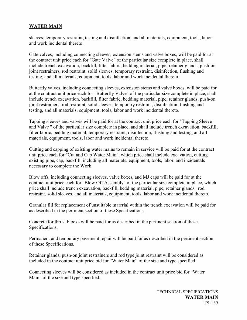
sleeves, temporary restraint, testing and disinfection, and all materials, equipment, tools, labor
and work incidental thereto.
Gate valves, including connecting sleeves, extension stems and valve boxes, will be paid for at
the contract unit price each for "Gate Valve" of the particular size complete in place, shall
include trench excavation, backfill, filter fabric, bedding material, pipe, retainer glands, push-on
joint restrainers, rod restraint, solid sleeves, temporary restraint, disinfection, flushing and
testing, and all materials, equipment, tools, labor and work incidental thereto.
Butterfly valves, including connecting sleeves, extension stems and valve boxes, will be paid for
at the contract unit price each for "Butterfly Valve" of the particular size complete in place, shall
include trench excavation, backfill, filter fabric, bedding material, pipe, retainer glands, push-on
joint restrainers, rod restraint, solid sleeves, temporary restraint, disinfection, flushing and
testing, and all materials, equipment, tools, labor and work incidental thereto.
Tapping sleeves and valves will be paid for at the contract unit price each for "Tapping Sleeve
and Valve " of the particular size complete in place, and shall include trench excavation, backfill,
filter fabric, bedding material, temporary restraint, disinfection, flushing and testing, and all
materials, equipment, tools, labor and work incidental thereto.
Cutting and capping of existing water mains to remain in service will be paid for at the contract
unit price each for "Cut and Cap Water Main", which price shall include excavation, cutting
existing pipe, cap, backfill, including all materials, equipment, tools, labor, and incidentals
necessary to complete the Work.
Blow offs, including connecting sleeves, valve boxes, and MJ caps will be paid for at the
contract unit price each for "Blow Off Assembly" of the particular size complete in place, which
price shall include trench excavation, backfill, bedding material, pipe, retainer glands, rod
restraint, solid sleeves, and all materials, equipment, tools, labor and work incidental thereto.
Granular fill for replacement of unsuitable material within the trench excavation will be paid for
as described in the pertinent section of these Specifications.
Concrete for thrust blocks will be paid for as described in the pertinent section of these
Specifications.
Permanent and temporary pavement repair will be paid for as described in the pertinent section
of these Specifications.
Retainer glands, push-on joint restrainers and rod type joint restraint will be considered as
included in the contract unit price bid for “Water Main” of the size and type specified.
Connecting sleeves will be considered as included in the contract unit price bid for “Water
Main” of the size and type specified.

WATER MAIN
TECHNICAL SPECIFICATIONS
WATER MAIN
TS-155A
Abandonment of valves will be considered as included in the contract unit price bid for “Water
Main” of the size and type specified.
Disinfection, flushing and testing of water mains and providing thrust restraint associated with
testing will be considered as included in the contract unit price bid for “Water Main” of the size
and type specified.
Removal from the job site, salvage and disposal of existing materials will be considered as
included in the contract unit price bid for “Water Main” of the size and type specified.
Trench excavation, backfill, filter fabric, bedding material and trench support systems, will be
considered as included in the contract unit price bid for “Water Main” of the size and type
specified.
Rock in trench excavation will be paid for as described in the “Excavation” section of these
Technical Specifications.
Removal of existing mains, valves and valve boxes, and salvage and disposal of existing
materials as indicated on the plans, within the limits of trench excavation or where directed by
the Engineer will be considered as included in the contract unit price bid for “Water Main” of the
size and type specified.
Open ends of abandoned pipelines or conduits that will not be removed from the roadway, shall
be sealed with concrete before backfilling and will be considered as included in the contract unit
price bid for “Water Main” of the size and type specified.
Abandonment of blow offs will be considered as included in the contract unit price bid for
“Water Main” of the size and type specified.
Pavement markings installed to replace disturbed markings will be considered as included in the
contract unit price bid for “Water Main” of the size and type specified.
Pump Station Retrofit will be paid for by the lump sum and shall include all materials,
equipment, tools, labor and incidentals to provide a complete installation.
Item No. Pay Item Pay Unit
60. 8” CLDIP Water Main Linear Foot
61. 12” CLDIP Water Main Linear Foot
62. 16” CLDIP Water Main Linear Foot
62A. 6” Gate Valve Each
63. 8” Gate Valve Each
64. 12” Gate Valve Each
65. 8” – 1/8 Ductile Iron Bend Each

WATER MAIN
TECHNICAL SPECIFICATIONS
WATER MAIN
TS-155B
66. 8” – 1/32 Ductile Iron Bend Each
67. 12” – 1/8 Ductile Iron Bend Each
68. 16” – 1/8 Ductile Iron Bend Each
69. 12” x 6” Ductile Iron Tee Each
70. 12” x 8” Ductile Iron Tee Each
71. 16” x 8” Ductile Iron Reducer Each
72. Pump Station Retrofit Each

HYDRANT ASSEMBLY Rev. Addendum No. 1 7-29-16
TECHNICAL SPECIFICATIONS
HYDRANT ASSEMBLY
TS-156
DESCRIPTION
“Hydrant Assembly” of the type required includes the furnishing and installation of new fire
hydrant assemblies off a new water main where shown on the plans or directed by the Engineer.
It shall include, but not be limited to, trench excavation and backfill, furnishing and installation
of the hydrant lead complete with hydrant tee, thrust block, pipe, fittings, auxiliary gate valve,
mechanical joint retainer glands, push-on joint restrainers and furnishing and installation of the
hydrant with concrete masonry units, drainage stone and painting after installation.
“Hydrant Assembly with Anchor Tee and Valve” of the size and type required includes the
furnishing and installation of new fire hydrant assemblies off an existing water main by means of
installing an anchor tee and valve where shown on the plans or as directed by the Engineer. It
shall include, but not be limited to, trench excavation and backfill, furnishing and installation of
the hydrant lead complete with anchor tee and auxiliary gate valve, thrust block, pipe, fittings,
mechanical joint retainer glands, push-on joint restrainers, cutting, removal anddisposal of
existing water main, and furnishing and installation of the hydrant with concrete masonry units,
drainage stone and painting after installation.
“Hydrant Assembly with Tapping Sleeve and Valve” of the size and type required includes the
furnishing and installation of new fire hydrant assemblies off an existing water main by means of
tapping sleeve and valve where shown on the plans or as directed by the Engineer. It shall
include, but not be limited to, trench excavation and backfill, furnishing and installation of the
hydrant lead complete with tapping sleeve and auxiliary gate valve, thrust block, pipe, fittings,
mechanical joint retainer glands, push-on joint restrainers, cutting, removal and disposal of
existing water main, and furnishing and installation of the hydrant with concrete masonry units,
drainage stone and painting after installation.
“Remove Hydrant Assembly” includes the removal of existing hydrant assemblies where shown
on the plans or as directed by the Engineer. It shall include, but not be limited to, salvaging the
existing hydrant; removing the existing hydrant tee from the main and replacing with new
cement-lined ductile iron pipe connected via solid sleeves; removing the valve box from the road
and sealing the open ends of the existing hydrant lead with concrete.
“Replace Hydrant Assembly” includes the furnishing and installation of new fire hydrant
assemblies to replace existing where shown on the plans or as directed by the Engineer. It shall
include, but not be limited to, trench excavation and backfill, furnishing and installation of the
hydrant lead complete with hydrant tee, thrust block, pipe, fittings, auxiliary gate valve,
mechanical joint retainer glands, push-on joint restrainers, furnishing and installation of the
hydrant with concrete masonry unit, drainage stone and painting after installation; removing the
existing hydrant assembly and salvaging the existing hydrant.
“Relocate Hydrant Assembly” includes the removal, storage, protection, reinstallation of existing
fire hydrant assemblies on the water distribution system, drainage stone and painting after
installation.
HYDRANT ASSEMBLY Rev. Addendum No. 1 7-29-16
TECHNICAL SPECIFICATIONS
HYDRANT ASSEMBLY
TS-157
MATERIALS
Hydrants: Hydrants shall be dry-barrel, post-type hydrants, with compression shut-
offs which open with the pressure. Hydrants shall meet the requirements
of AWWA C502. They shall have a main valve opening of 5-1/4 inches
and have a 6-inch mechanical joint inlet. Bury length shall be 5-1/2 feet.
Two 2-1/2 inch hose and one 4-1/2 inch pumper nozzles shall be provided
in standard nozzle arrangement. Outlet nozzle threads shall meet the
requirements of ANSI B26, "National Standard Fire-Hose Coupling Screw
Threads." Hydrants shall be of break flange construction, shall have 0-
ring seals and shall be right opening (clockwise) or left opening
(counter clockwise) as indicated on the plans or as directed by the
Engineer, which is dependent on where they are located in Town.
Interior and exterior coatings shall meet the requirements of the latest
revision of AWWA C502, and the color for that portion of the hydrant
above the ground line shall be as directed by the Manchester Water
Department.
In addition, that portion of each hydrant below finished grade shall be
given a coating of hot bitumastic material, equal to that used for exterior
coating of pipe and fittings, prior to installation. A drain outlet is required.
Hydrants shall be Eddy Model F-2640 manufactured by Clow
Corporation, Bensenville, Illinois, the Pacer Model WB-67 with 16”
traffic section manufactured by Waterous, South St. Paul, Minnesota, the
Metropolitan 250-Model 94 manufactured by U.S.Pipe and Foundry Co.,
Birmingham, AL., or Super Centurion 250 by Mueller Co., Decatur, IL.
Hydrants shall be installed so as to maintain an 18-inch nozzle height
above finished grade without use of extension sections.
The type of hydrant to be installed shall be determined in the field by the
Engineer.
Post Hydrant: Post hydrants shall be self-draining, non-freezing, compression type with
2-1/8" main opening. Inlet shall be 2" FNPT. Outlet nozzle shall be 2"
MNPT. Hydrants shall have a ductile iron exterior casing pipe, a
galvanized interior non-turning operating rod with a heavy wall cast iron
top stock and a bolted breakaway flange. Principal interior operating parts
shall be brass, bronze and aluminum and shall be removable for servicing
without excavating the hydrant. Bury depth shall be 5’-6”. Hydrant shall
be set in 4 cubic feet of crushed stone to allow for proper drainage of the
hydrant. Hydrant shall be equipped with cross connection prevention and a
locking feature. Hydrants shall be #2 Eclipse Post Hydrant as

HYDRANT ASSEMBLY Rev. Addendum No. 1 7-29-16
TECHNICAL SPECIFICATIONS
HYDRANT ASSEMBLY
TS-158
manufactured by John C. Kupferle Company, St. Louis, MO or approved
equal.
Ductile Iron Pipe: Ductile iron push-on joint pipe shall meet the requirements specified in the
pertinent section of these Technical Specifications.
Fittings: Mechanical joint fittings, exterior and interior coatings, and valve boxes
shall meet the requirements specified in the pertinent section of these
Technical Specifications.
Anchor Tee: Mechanical joint anchor tees shall be used to connect the hydrant lead to
the water main.
Auxiliary Gate All auxiliary gate valves shall be resilient wedge gate valves and shall
Valves: meet the requirements specified in the pertinent section of these Technical
Specifications. Auxiliary gate valves shall be right opening (clockwise)
or left opening (counterclockwise) as indicated on the plans or as
directed by the Engineer, which is dependent on where they are
located in Town.
Tapping Sleeves All tapping sleeve and valve configurations and installations shall meet the
and Valves: requirements specified in the pertinent section of these Technical
Specifications.
Hydrant Paint: Paint for hydrants shall be high performance industrial coating alkyd
enamel. Paint shall have a high gloss finish. Paint colors shall be Fire
Hydrant Red (245385) for left-opening (counter clockwise) hydrants or
Yellow (245488) for right-opening (clockwise) hydrants as manufactured
by Rust-Oleum Corporation or approved equal. Surface preparation and
paint application after hydrant installation shall be in accordance with the
manufacturer’s recommendations.
Concrete: Concrete shall meet the requirements of Section M.03.01 of Form 816 for
Class "A." Precast concrete masonry units shall meet the requirements of
ASTM C139.
Bedding Material: Three-quarter inch crushed stone shall meet the gradation requirements
specified for stone and gravel in Section M.01.01 of Form 816.
Joint Restraint: Mechanical joint retainer glands and push-on joint restrainers shall meet
the requirements specified in the pertinent section of these Technical
Specifications.

HYDRANT ASSEMBLY Rev. Addendum No. 1 7-29-16
TECHNICAL SPECIFICATIONS
HYDRANT ASSEMBLY
TS-159
Connecting Sleeves: Sleeves for connecting new water mains to existing water mains shall be
as described in the pertinent section of these Technical Specifications.
CONSTRUCTION DETAILS
Trench excavation and backfill, installation of water main and appurtenances, testing,
disinfection, pavement repair and surface restoration will be carried out as defined in the
pertinent sections of these Technical Specifications.
Fire hydrants shall be provided and located as shown on the plans or as directed by the Engineer.
Installation shall be as detailed on the plans and as defined in these Technical Specifications.
Hydrants shall stand plumb with the center a minimum of 2’-6” from the face of curb or edge of
road. Hydrant nozzles shall be parallel with, or at right angles to the road, with the pumper
nozzle facing the road. Hydrants shall be set to the established grade with a 5-1/2 foot bury and
with nozzles 18 inches above the ground or as directed by the Engineer without the use of
extension sections. It is the Contractor’s responsibility to ensure final nozzle height is based on
the finished grades shown on the plans and shall request clarification from the Engineer if
proposed grades are unclear.
A mechanical joint offset or two 1/8 bends shall be utilized in the hydrant lead to achieve the
proper grade of the fire hydrant when the depth of the water main does not permit these
requirements to be met using only straight pipe. Offset or bends shall be located as close to the
auxiliary gate valve as field conditions permit.
Auxiliary gate valves shall be set in accordance with the requirements of the pertinent section of
these Technical Specifications. Depth of bury shall be as shown on the plans.
Tapping sleeve and auxiliary gate valves shall be installed in accordance with requirements of
the pertinent section of these Technical Specifications.
All mechanical joints in hydrant leads shall have ductile iron retainer glands.
All push-on joints in hydrant leads shall have push-on joint restrainers.
A poured concrete thrust block shall be provided behind the hydrant. The thrust block shall rest
against undisturbed earth and shall not obstruct the hydrant drain.
A concrete collar shall be poured around the hydrant barrel as indicated on the plans.
The Contractor shall place and secure a burlap bag or plastic bag over each new hydrant
indicating the hydrant is “out-of service” and shall be responsible for maintaining this
HYDRANT ASSEMBLY Rev. Addendum No. 1 7-29-16
TECHNICAL SPECIFICATIONS
HYDRANT ASSEMBLY
TS-160
identification until the hydrant is put into service, at which time the cover shall be removed and
disposed of.
All existing hydrants that are removed or replaced shall be salvaged. The hydrants shall be
delivered to the Water Department facilities on Line Street, Manchester. The Contractor shall be
responsible for properly unloading all salvaged materials.
Where the plans call for existing hydrants to be removed (but not replaced), the existing hydrant
shall be salvaged and the existing hydrant tee shall be removed from the main and replaced with
new cement-lined ductile iron pipe connected to the existing main using solid sleeves. The valve
box shall be removed from the road and the open ends of the existing hydrant lead shall be sealed
with concrete.
Where the plans call for existing hydrants to be replaced, the existing hydrant shall be salvaged
and the existing hydrant tee shall be removed from the main. The existing hydrant assembly shall
be replaced with a new hydrant assembly in accordance with the provisions of this section.
Where excavations are to be made in grass covered areas, loam and topsoil shall be carefully
removed and separately stored to be used again. If the Contractor prefers not to separate surface
materials he shall furnish, as directed by the Engineer, loam and topsoil at least equal in quality
to that excavated.
Hydrants shall be painted after installation entirely red or yellow based on the opening direction
as specified herein.
MEASUREMENT
“Hydrant Assembly”, “Hydrant Assembly with Tapping Sleeve and Valve” and “Hydrant
Assembly with Anchor Tee and Valve” will be measured as units, of the particular type,
complete and accepted. Measurement shall be from and inclusive of the tee (or tapping sleeve
and valve) at the water main to back of the hydrant. Units measured under this item shall include
the installation of new hydrant assemblies only.
“Remove Hydrant Assembly” will be measured as units, complete and accepted. Units shall be
measured under this item only when a new hydrant assembly is not being installed at the location
of the existing hydrant assembly. When an existing hydrant to be removed is located within the
trench excavation limits of a new hydrant assembly, the removal of the existing hydrant
assembly will not be measured for payment, but its costs shall be considered as included in the
bid price for “Replace Hydrant Assembly”.
“Replace Hydrant Assembly” as indicated on the Plan will be measured as units, complete and
accepted. This shall include both the removal of existing hydrant assembly and the installation of

HYDRANT ASSEMBLY Rev. Addendum No. 1 7-29-16
TECHNICAL SPECIFICATIONS
HYDRANT ASSEMBLY
TS-161
a new hydrant assembly. Measurement shall be from and inclusive of the tee (or tapping sleeve
and valve) at the water main to the back of the hydrant.
“Relocate Hydrant Assembly” as indicated on the Plan will be measured as units, complete and
accepted. This shall include both the removal of existing hydrant, storage, protection and
reinstallation of the existing hydrant assembly. Measurement shall be from and inclusive of the
nearest fitting on the water main to the back of the hydrant.
Excavation, backfill, storage, protection, salvage and delivery of existing hydrants,
removal/disposal of existing materials (i.e. pipes, tees, valve boxes, hydrant leads etc.),
abandonment of existing hydrant leads, thrust blocks, connecting sleeves, nipple pieces, retainer
glands, push-on pipe joint restrainers, rod type joint restraint, hydrant tees, bends, offsets,
hydrant leads, hydrant gate valves, concrete collars and other appurtenances will not be
measured separately for payment but the cost shall be considered as included in the price bid for
the Work.
Surface restoration will be measured for payment as described in the pertinent section of these
Technical Specifications.
PAYMENT
“Hydrant Assembly” will be paid for at the contract unit price each for "Hydrant Assembly”
installed off a new water main, of the particular type completed and accepted, which price shall
include trench excavation, backfill, removal, furnishing, installation of hydrant tee, hydrant gate
valve and valve box, the hydrant lead and hydrant, offset (Type B Hydrant Assembly), 1/8 bends
(Type C Hydrant Assembly), mechanical joint retainer glands, push-on pipe joint restrainers,
drainage stone, thrust block, concrete collar, as well as testing and disinfection, including all
materials, equipment, tools, labor and incidentals necessary to complete the Work.
“Hydrant Assembly with Anchor and Valve” will be paid for at the contract unit price each for
"Hydrant Assembly with Anchor Tee and Valve” of the size and type required installed off an
existing water main, completed and accepted, which price shall include trench excavation,
backfill, removal, furnishing, installation of anchor tee and valve, valve box, the hydrant lead
and hydrant, offset (Type B Hydrant Assembly), 1/8 bends (Type C Hydrant Assembly),
mechanical joint retainer glands, push-on pipe joint restrainers, drainage stone, thrust block,
concrete collar, as well as testing and disinfection, including all materials, equipment, tools,
labor and incidentals necessary to complete the Work.
“Hydrant Assembly with Tapping Sleeve and Valve” will be paid for at the contract unit price
each for "Hydrant Assembly with Tapping Sleeve and Valve” of the size and type required
installed off an existing water main, completed and accepted, which price shall include trench
excavation, backfill, removal, furnishing, installation of tapping sleeve and valve, valve box, the
hydrant lead and hydrant, offset (Type B Hydrant Assembly), 1/8 bends (Type C Hydrant

HYDRANT ASSEMBLY Rev. Addendum No. 1 7-29-16
TECHNICAL SPECIFICATIONS
HYDRANT ASSEMBLY
TS-162
Assembly), mechanical joint retainer glands, push-on pipe joint restrainers, drainage stone, thrust
block, concrete collar, as well as testing and disinfection, including all materials, equipment,
tools, labor and incidentals necessary to complete the Work.
“Remove Hydrant Assembly” will be paid for at the contract unit price each for "Remove
Hydrant Assembly" complete and accepted, which price shall include trench excavation, backfill,
removal, salvage and delivery of existing hydrant, removal/disposal of existing materials (i.e.
tees, valve boxes, hydrant leads, etc.), furnishing and installation of replacement pipe, solid
sleeves, retainer glands, thrust restraint, testing and disinfection, including all materials,
equipment, tools, labor and work incidental. When an existing hydrant to be removed is located
within the trench excavation limits of a new hydrant assembly, the removal of the existing
hydrant assembly will not be paid for separately; the cost shall be considered as included in the
bid price for “Replace Hydrant Assembly”.
“Replace Hydrant Assembly” will be paid for at the contract unit price each for “Replace
Hydrant Assembly” complete and accepted, which price shall include trench excavation, backfill,
removal, salvage and delivery of existing hydrants, removal/disposal of existing materials (i.e.
tees, valve boxes, hydrant leads, etc.), furnishing and installation of new hydrant tee, hydrant
gate valve and valve box, the hydrant lead and hydrant, offset (Type B Hydrant Assembly), 1/8
bends (Type C Hydrant Assembly), mechanical joint retainer glands, push-on pipe joint
restrainers, drainage stone, thrust block, concrete collar, as well as testing and disinfection,
including all materials, equipment, tools, labor and incidentals necessary to complete the Work.
“Relocate Hydrant Assembly” will be paid for at the contract unit price each for “Relocate
Hydrant Assembly” complete and accepted, which price shall include trench excavation, backfill,
removal, storage, protection and reinstallation of existing hydrants, removal/disposal of existing
materials (i.e. tees, valve boxes, hydrant leads, etc.), replacing or adjusting the nearest existing
fitting, furnishing and installing mechanical joint retainer glands, push-on pipe joint restrainers,
drainage stone, thrust block and concrete collar as required, as well as testing and disinfection,
including all materials, equipment, tools, labor and incidentals necessary to complete the Work.
Item No. Pay Item Pay Unit
73. Post Hydrant Assembly Each
74. Hydrant Assembly with Tapping Sleeve and Valve Each
MODIFY TRAFFIC SIGNAL
TECHNICAL SPECIFICATIONS
MODIFY TRAFFIC SIGNAL
TS-285
DESCRIPTION
“Modify Traffic Signal” shall consist of the modification of the existing traffic control signal at
Charter Oak Street as shown on the Plan and as specified herein.
MATERIALS
All work shall conform with Form 816 and attached Special Provisions.
CONSTRUCTION DETAILS
All work shall conform with Form 816 and attached Special Provisions.
MEASUREMENT AND PAYMENT
“Modify Traffic Signal” will be measured for payment by the lump sum. The Contractor shall
submit a schedule of values to the Engineer for approval based upon the different items
associated with this work for partial payment purposes. The lump sum unit price shall include
all materials, labor, equipment, tools and incidentals required for the work shown and necessary
to install a complete system as shown on the Plans. It includes all work shown on the Plan
associated with the signal modification.
Item No. Pay Item Pay Unit
100. Modify Traffic Signal Lump Sum

Rev. Date 2/00 Page 1 of 1
ITEM #1008908A
ITEM# 1008908A - CLEAN EXISTING CONDUIT
Description: Clean existing conduit as required, as shown on the plans or as directed by the Engineer to
remove dirt and debris to facilitate the installation of new cable.
Construction Methods: Where cable is to be installed in existing conduit the conduit may have to be cleared prior to the
installation. Cleaning will only be necessary if the new cable cannot be easily installed in the existing
conduit. By field inspection, and with the concurrence of the Engineer, determine the sections of conduit
that require cleaning.
Remove all existing cable from conduit. Install temporary cable elsewhere, as necessary, to
maintain normal signalization complete with vehicle & pedestrian detection, EVPS, and coordination.
Clean the conduit by one of the following methods:
1) Rodding.
2) A high pressure jet spray, or air pressure.
3) By pulling a mandrel or ball through the conduit.
Submit in writing the anticipated method of cleaning the conduit to the Engineer for approval
prior to cleaning any conduit.
If the conduit is found damaged to any extent that the cleaning process will not clear the
obstruction, it will be the judgment of the Engineer whether to replace the entire conduit run or excavate
and replace only the damaged section.
If the existing conduit is found to be missing hardware such as bonding bushings and bond wire,
the missing material shall be provided and installed under this item prior to installation of the cable.
TS-286

Rev. Date 2-14 1 of 1
ITEM #1010060A
ITEM #1010060A – CLEAN EXISTING CONCRETE HANDHOLE
DESCRIPTION:
Clean all debris from an existing concrete handhole where shown on the plans or as
directed.
MATERIAL:
Insulated Bonding Bushings:
Specification Grade
Threaded
Malleable Iron or Steel
Galvanized
UL listed
Bonding Wire:
M.15.13
Grout:
M.03.05
CONSTRUCTION METHODS:
Remove to a level even with the bottom of the handhole all sand, silt and other debris.
Remove any material that is accessible from the ends of conduit. Additional conduit cleaning
will be paid for under Item 1008908A-Clean Existing Conduit. Place approximately 4” (100) of
¾” (19) crushed stone in bottom of handhole using care not to allow crushed stone to enter
conduits. Grout around conduits to prevent future entrance of dirt and silt. Properly dispose all
removed debris. Inspect bonding bushings. Tighten loose bushings. Secure loose bond
connections. Install new bonding bushings on spare conduits and bond to other conduits.
TS-287

Rev. Date 6-15 1 of 1
ITEM #1002291A
ITEM #1002291A - MODIFICATION OF TRAFFIC CONTROL
FOUNDATION
Description: This item shall consist of modifying existing traffic control foundation of the type specified at the locations shown on the plans or as directed by the Engineer and in conformity with these special provisions. Materials: Concrete replacement shall be Class "A" concrete conforming to Section M.03 and for Rigid Metal Conduit, Article M.15.09. Concrete bonding compound shall be of an approved type as directed by the Engineer. Construction Methods: All work shall be in accordance with the following procedure or as directed by the Engineer. a) Remove concrete foundation by cutting, chiseling or any other method approved by the
Engineer as required to install new conduit sweeps. b) Position new conduit sweeps, and apply an approved concrete bonding compound on
the exposed concrete surfaces as recommended by the manufacturer. c) Forms shall be positioned so that all existing exposed foundation at grade level or above
will be matched. All work shall be in accordance with Section 6.01. d) Allow concrete to cure and backfill as indicated on the details. When all conduits, existing and new, are used, one additional 50mm (2”) rigid metal conduit sweep shall be installed as a spare. Existing conduits that will be abandoned shall be cut and capped approximately two feet from the foundation. Surfaces, new and existing, of a foundation which is modified, shall be "Grout
Clean-Down Finish" as described in Section 6.01.
Where a foundation is modified within or adjacent to a concrete sidewalk, unless
otherwise directed by the Engineer, the entire section of sidewalk shall be replaced in accordance
with Section 9.21.
TS-288

Rev. Date 12-14
1 of 4
ITEM #1105301A
ITEM #1105301A - 1 WAY, 3 SECTION PEDESTAL MOUNTED
TRAFFIC SIGNAL
Article 11.05.03 – Construction Methods:
Add the following paragraph:
Circular indications that have an identification mark (such as an arrow) on the top of the lens shall be installed with that mark at the 12 o-clock position.
Article M.16.06 - Traffic Signals
Sub Article 3 - Housing:
In the last sentence, between the words “housing” and “shall” add “and all internal
hardware”.
Add the following after the last paragraph.
Each section of the housing shall be provided with a removable visor. The visor shall be
the cap type, unless otherwise noted on the plan. The visor shall be a minimum .05 inch (.13
mm) thick. The visor shall be the twist on type and secured to the signal by four equidistant flat
tabs screwed to the signal head.
Sub Article 4 - Brackets:
Add the following at the end of the last paragraph:
Install a 2” wide yellow retroreflective strip (Type IV sheeting) along the perimeter of the
face of the backplate.
Delete Sub Article 5 - Optical Unit and Sub Article 6 – Lamp Socket and replace with the
following:
Optical Unit, Light Emitting Diode:
(a) General:
Only Optical Units that meet the requirements contained herein supplied by the below
manufacturers that have been tested by the Department’s Signal Lab will be accepted. Final
approval for model numbers will be done at the time of the catalog cut submittals.
Duralight GE Lighting Solutions
TS-289
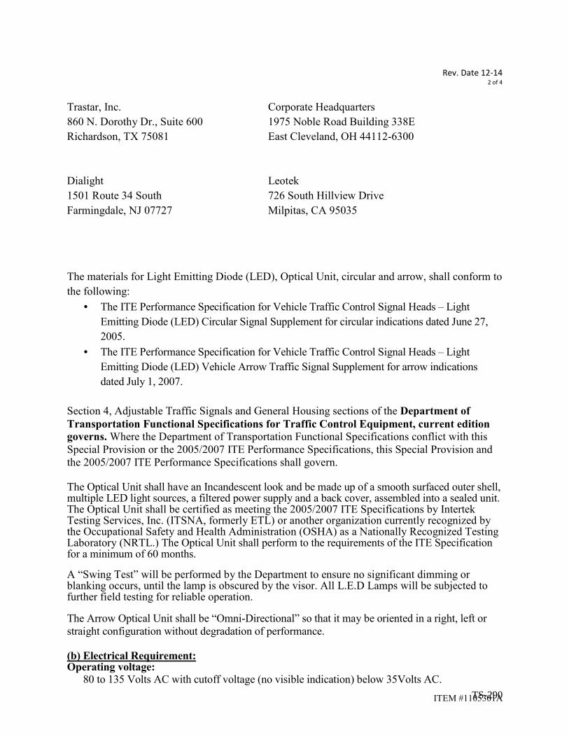
Rev. Date 12-14
2 of 4
ITEM #1105301A
Trastar, Inc. Corporate Headquarters
860 N. Dorothy Dr., Suite 600 1975 Noble Road Building 338E
Richardson, TX 75081 East Cleveland, OH 44112-6300
Dialight Leotek
1501 Route 34 South 726 South Hillview Drive
Farmingdale, NJ 07727 Milpitas, CA 95035
The materials for Light Emitting Diode (LED), Optical Unit, circular and arrow, shall conform to
the following:
• The ITE Performance Specification for Vehicle Traffic Control Signal Heads – Light
Emitting Diode (LED) Circular Signal Supplement for circular indications dated June 27,
2005.
• The ITE Performance Specification for Vehicle Traffic Control Signal Heads – Light
Emitting Diode (LED) Vehicle Arrow Traffic Signal Supplement for arrow indications
dated July 1, 2007.
Section 4, Adjustable Traffic Signals and General Housing sections of the Department of
Transportation Functional Specifications for Traffic Control Equipment, current edition
governs. Where the Department of Transportation Functional Specifications conflict with this
Special Provision or the 2005/2007 ITE Performance Specifications, this Special Provision and
the 2005/2007 ITE Performance Specifications shall govern.
The Optical Unit shall have an Incandescent look and be made up of a smooth surfaced outer shell, multiple LED light sources, a filtered power supply and a back cover, assembled into a sealed unit. The Optical Unit shall be certified as meeting the 2005/2007 ITE Specifications by Intertek Testing Services, Inc. (ITSNA, formerly ETL) or another organization currently recognized by the Occupational Safety and Health Administration (OSHA) as a Nationally Recognized Testing Laboratory (NRTL.) The Optical Unit shall perform to the requirements of the ITE Specification for a minimum of 60 months.
A “Swing Test” will be performed by the Department to ensure no significant dimming or blanking occurs, until the lamp is obscured by the visor. All L.E.D Lamps will be subjected to further field testing for reliable operation.
The Arrow Optical Unit shall be “Omni-Directional” so that it may be oriented in a right, left or
straight configuration without degradation of performance.
(b) Electrical Requirement: Operating voltage: 80 to 135 Volts AC with cutoff voltage (no visible indication) below 35Volts AC.
TS-290

Rev. Date 12-14
3 of 4
ITEM #1105301A
Power requirements:
Circular Indications: 12”, (300 mm) – no more than 16 Watts
Circular Indications: 8”, (200mm) - no more than 16 Watts
Arrows Indications: 12”, (300mm) - no more than 16 Watts
Power Supply: Fused and filtered to provide excess current protection and over voltage protection from electrical surges and transient voltages. (c) Photometric Requirement: Beam Color: Meet 2005/2007 ITE Specifications (d) Mechanical Requirements: Diameter: The Circular Optical Unit shall fit into standard 12” (300mm) or 8” (200mm) housing. The Arrow Optical Unit shall fit 12” (300mm) housings only. Enclosure: UV (Ultraviolet) stabilized polycarbonate back cover. Clear lens cover for all Red, Yellow and Green Circular Optical Units. For Arrow Optical Units the arrow indication segment of the lens shall be clear. Enclosure sealed and waterproofed to eliminate dirt contamination and be suitable for installation in all weather conditions. Clearly mark on the housing the following information:
• Manufacturer & model number
• Date of manufacture (must be within one year of installation)
The model number shall end with the number of LEDs used to comprise the unit as the last digits of the model number. Example, if the unit comprised of 3 LEDs and the model is x12y, then the new model number shall read x12y3. Operating temperature: Meet 2005/2007 ITE Specification Wiring: L.E.D. lamps shall have color coded 16 AWG wires for identification of heads as follows:
RED L.E.D. Lamps RED with WHITE neutral
YELLOW L.E.D. Lamps YELLOW with WHITE neutral
GREEN L.E.D. Lamps GREEN or Brown with WHITE neutral
RED L.E.D. ARROWS RED/WHITE with WHITE neutral
YELLOW L.E.D. ARROWS YELLOW/WHITE with WHITE neutral
TS-291

Rev. Date 12-14
4 of 4
ITEM #1105301A
GREEN L.E.D. ARROWS GREEN/WHITE or BROWN/WHITE with WHITE neutral
GREEN/YELLOW LE.D ARROWS GREEN/WHITE or BROWN/WHITE, YELLOW/WHITE, with WHITE
neutral
Wires shall be terminated with a Block Spade, 6-8 stud/ 16-14 wire size.
All Circular Optical Units shall be supplied with a minimum 40” pigtail and all Arrow
Optical Units Supplied with a minimum 60” pigtail.
Sub Article 9 - Painting: Third coat: Replace the first two sentences with the following: All brackets and hardware shall be painted yellow by the manufacturer. The color shall be No. 13538, Federal Standard No. 595. At intersections at Merritt Parkway interchanges, all brackets and hardware shall be painted dark green by the manufacturer. The color shall be No. 14056, Federal Standard No. 595.
TS-292

Rev. Date 3-131 of 2
ITEM #1106001A, #1106003A
ITEM#1106001A- 1 WAY PEDESTRIAN SIGNAL POLE MOUNTED
ITEM#1106003A- 1 WAY PEDESTRIAN SIGNAL PEDESTAL MOUNTED
Section 11.06.02 Pedestrian Signal, Materials
Section M.16.07 C. Optical Unit
Delete 2. LED: and replace with the following:
General Meet requirements of current MUTCD Section 4E. Meet current ITE specifications for Pedestrian Traffic Control Signal Indications -
(PTCSI) Part 2: Light Emitting Diode (LED). Meet CT DOT, 2008 - 2010 Functional Specifications for Traffic Control Equipment;
Section 5D, LED Pedestrian Signal with Countdown Timer. Meet EPA Energy Star® requirements for LED Pedestrian Signal Modules.
Operational Countdown display only during the flashing Pedestrian Clearance (Ped Clr) Interval.
Timer goes blank at end of flashing ped clr even if countdown has not reached zero.
Physical Sealed optical module to prevent entrance of moisture and dust. Self-contained optical module, including necessary power supplies. Designed to securely fit into standard housing without the use of special tools or
modifications to the housing. Identification information on module: manufacturer’s name, model number, serial
number, and date code.
Optical Multiple LED sources; capable of partial loss of LED’s without loss of symbol or
countdown message. Two complete self contained optical systems. One to display the walking person
symbol (walk) and the hand symbol (don’t walk). One to display the countdown timer digits.
Visual Image similar to incandescent display; smooth, non-pixilated. Symbol and countdown digit size as shown on the plan. Solid hand/person symbol; outline display not allowed. Overlaid hand/person symbols and countdown digits arranged side by side. Countdown digit display color: Portland Orange in accordance with ITE requirements. Countdown digits comprised of two seven segments, each in a figure 8 pattern. Photometric Requirements: Luminance, Uniformity, and Distribution in accordance
with ITE requirements. Color Uniformity in accordance with ITE requirements. Blank–Out design; symbols and digits illegible even in direct sunlight when not
illuminated.
TS-293

Rev. Date 3-132 of 2
ITEM #1106001A, #1106003A
Electrical Operating voltage: 89 VAC to 135 VAC. Low Voltage Turn-Off: 35 VAC. Turn-On and Turn-Off times in accordance with ITE specifications. Combined Hand – Countdown Digits wattage: > 20 Watts. Input impedance at 60 Hertz sufficient to satisfy Malfunction Management Unit
(MMU) requirements. Two separate power supplies. One to power the walking person symbol. One to power
the hand symbol and the countdown digits. Meet Federal Communication Commission (FCC) regulations concerning electronic
noise. Filtered and protected against electrical transients and surges.
Warrantee Five years from date ownership is accepted.
Section M.16.07 F. Painting:
Third coat: Replace the first two sentences with the following:
All brackets and hardware shall be painted yellow by the manufacturer. The color shall be No. 13538, Federal Standard No. 595.
At intersections at Merritt Parkway interchanges, all brackets and hardware shall be painted dark green by the manufacturer. The color shall be No. 14056, Federal Standard No. 595.
TS-294
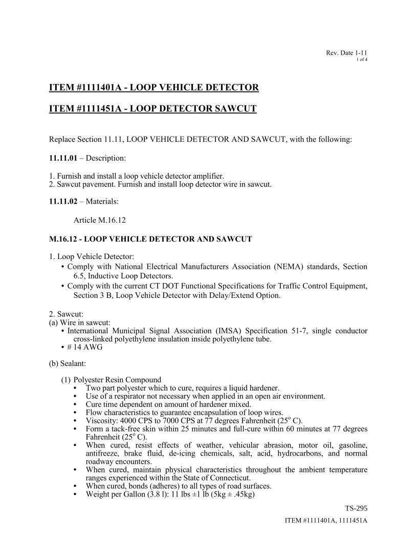
Rev. Date 1-11 1 of 4
ITEM #1111401A, 1111451A
ITEM #1111401A - LOOP VEHICLE DETECTOR
ITEM #1111451A - LOOP DETECTOR SAWCUT
Replace Section 11.11, LOOP VEHICLE DETECTOR AND SAWCUT, with the following:
11.11.01 – Description:
1. Furnish and install a loop vehicle detector amplifier. 2. Sawcut pavement. Furnish and install loop detector wire in sawcut. 11.11.02 – Materials:
Article M.16.12
M.16.12 - LOOP VEHICLE DETECTOR AND SAWCUT 1. Loop Vehicle Detector:
• Comply with National Electrical Manufacturers Association (NEMA) standards, Section
6.5, Inductive Loop Detectors.
• Comply with the current CT DOT Functional Specifications for Traffic Control Equipment,
Section 3 B, Loop Vehicle Detector with Delay/Extend Option.
2. Sawcut: (a) Wire in sawcut:
• International Municipal Signal Association (IMSA) Specification 51-7, single conductor cross-linked polyethylene insulation inside polyethylene tube.
• # 14 AWG (b) Sealant:
(1) Polyester Resin Compound • Two part polyester which to cure, requires a liquid hardener. • Use of a respirator not necessary when applied in an open air environment. • Cure time dependent on amount of hardener mixed. • Flow characteristics to guarantee encapsulation of loop wires. • Viscosity: 4000 CPS to 7000 CPS at 77 degrees Fahrenheit (25
o C).
• Form a tack-free skin within 25 minutes and full-cure within 60 minutes at 77 degrees Fahrenheit (25
o C).
• When cured, resist effects of weather, vehicular abrasion, motor oil, gasoline, antifreeze, brake fluid, de-icing chemicals, salt, acid, hydrocarbons, and normal roadway encounters.
• When cured, maintain physical characteristics throughout the ambient temperature ranges experienced within the State of Connecticut.
• When cured, bonds (adheres) to all types of road surfaces. • Weight per Gallon (3.8 l): 11 lbs ±1 lb (5kg ± .45kg)
TS-295

Rev. Date 1-11 2 of 4
ITEM #1111401A, 1111451A
• Show no visible signs of shrinkage after curing. • 12 month shelf life of unopened containers when stored under manufacturers
specified conditions. • Cured testing requirements:
• Gel time at 77 degrees F (25° C): 15 - 20 minutes, ASTM C881, D-2471 • Shore D Hardness at 24 hours: 55-78, ASTM D-2240 • Tensile Strength: > 1000 psi (6895 kPa), ASTM D-638 • Elongation: 18 - 20 %, ASTM D-638 • Adhesion to steel: 700 - 900 psi (4826 - 6205 kPa), ASTM D-3163 • Absorption of water, sodium chloride, oil, and gasoline: < 0.2%, ASTM D-570
• Include in the Certificate of Compliance: • Manufacturer’s confirmation of the uncured and cured physical properties
stated above. • Material Safety Data Sheet (MSDS) stating sealant may be applied without a
respirator in an open air environment. • Designed to allow clean-up without the use of solvent that is harmful to the workers
and the environment.
(2) Elasotmeric Urethane Compound: • One part urethane which to cure, does not require a reactor initiator, or a source of
thermal energy prior to or during its installation. • Use of a respirator not necessary when applied in an open air environment. • Cure only in the presence of moisture. • Flow characteristics to guarantee encapsulation of loop wires. • Viscosity such that it does not run out of the sawcut in sloped pavement during
installation; 5000 CPS to 85,000 CPS. • Form a tack-free skin within 24 hours and 0.125 inch (0.33mm) cure within 30 hours at
75 degrees Fahrenheit (24o C).
• When cured, resist effects of weather, vehicular abrasion, motor oil, gasoline, antifreeze, brake fluid, de-icing chemicals, salt, acid, hydrocarbons, and normal roadway encounters.
• When cured, maintain physical characteristics throughout the ambient temperature ranges experienced within the State of Connecticut.
• Show no visible signs of shrinkage after curing. • Shelf life when stored under manufacturers specified conditions:
• Caulk type cartridges: minimum 9 months • Five gallon containers: minimum 12 months
• Designed for application when the pavement surface temperature is between 40 and 100 degrees Fahrenheit (4
o and 38
o C).
• Uncured testing requirements: • Weight/Gallon: ASTM D-1875 • Determination of Non-volatile Content: ASTM D-2834 • Viscosity: ASTM D-1048B • Tack-free Time: ASTM D-1640
• Cured testing requirements: • Hardness: ASTM D-2240 • Tensile Strength & Elongation: ASTM D-412A
• Include in the Certificate of Compliance: • Manufacturer’s confirmation of the uncured and cured physical properties
stated above. • Material Safety Data Sheet (MSDS) stating sealant may be applied without a
respirator in an open air environment.
TS-296

Rev. Date 1-11 3 of 4
ITEM #1111401A, 1111451A
• Designed to allow clean-up without the use of solvent that is harmful to the workers and the environment.
3. Miscellaneous:
(a) Liquidtight Flexible Nonmetallic Conduit • UL listed for direct burial • UL 1660 • Smooth polyvinyl chloride inner surface
(b) Water Resistant Pressure Type Wire Connector
• Ul listed for direct burial and wet locations • UL 486D
11.11.03 - Construction methods:
1. Loop Vehicle Detector
• Shelf-mount the detector amplifier in the controller cabinet. • Terminate the harness conductors with crimped spade connectors. Connect conductors to
appropriate terminals, eg, black wire to 110vac, white wire to 110vac neutral. • Tie loop harness and conductors to controller cabinet wiring harness. Leave enough slack in
loop harness so that amplifier may be moved around on cabinet shelf; ± 2 feet (0.6 meter) slack.
• Attach a loop identification tag to the harness. Record pertinent detector information on the tag with indelible ink. See example below.
o Loop No.: D4 o Phase Call: Phase 4 o Field Location: Rt. 411(West St.) o Eastbound, Left Lane o Detector No.: 4 o Cabinet Terminals: 234, 235
2. Loop Detector Sawcut
• Loop size, number of turns, and location is shown on the intersection plan. • Do not cut through a patched trench, damaged or poor quality pavement without the approval
of the Engineer. • Wet-cut pavement with a power saw using a diamond blade ⅜ inch (9.5mm) wide. Dry-cut is
not allowed. • Ensure slot depth is between 1 ¾ inch to 2.0 inch (45mm to 50mm). • Overlap corners to ensure full depth of cut. • To prevent wire kinking and insulation damage, chamfer inside of corners that are ≤ 120
degrees. • Clean all cutting residue and moisture from slot with oil-free compressed air. Ensure slot is
dry before inserting wire and sealing sawcut. • Cut home-run, from loop to curb or edge-of-road, as shown on the typical installation sheet. • To prevent cross-talk and minimize electrical interference, twist home-run wires, from edge
of road to handhole, with at least 5 turns per foot (16 turns per meter). Tape together twisted home-run wires at 2 foot (0.6 meter) ± intervals.
• In new or resurfaced pavement, install loops in the wearing course. If the wearing course is not scheduled for immediate placement (within 24 hours) after the base course, provide temporary detection when directed by the Engineer. Temporary detection may be sawcut
TS-297

Rev. Date 1-11 4 of 4
ITEM #1111401A, 1111451A
loops, preformed loops, microwave sensor, video, or other method approved by the Engineer.
• Splice(s) not allowed anywhere in loop wire either in loop or in home-run. • Ensure wires are held in place at bottom of slot by inserting at 2 foot (0.6 m) intervals, 1 inch
sections of foam backer rod or wedges formed from 1 inch (25mm) sections of the polyethylene tubing. Loop detectors with wires that have floated to the top of the sealant will not be accepted.
• To create a uniform magnetic field in the detection zone, wind adjacent loops in opposite directions.
• Use polyester compound as the sealant unless another type is allowed by the Engineer. • Mix hardening agent into polyester resin with a power mixer or in an application machine
designed for this type of sealant in accordance with the manufacturer’s instructions. • Apply the loop sealant in accordance with the manufacturer’s instructions and the typical
installation sheet. Do not apply sealant when pavement temperature is outside the manufacturers recommended application range.
• Solder splice the loop wires to the lead-in cable and install water resistant connector as shown on the typical installation sheet.
• Test the loop circuit resistance, inductance, and amplifier power-interruption as shown on the typical installation sheet. Document all test results.
3. Damaged, Patched, or Excessively Worn Pavement
• Where the existing pavement is damaged, patched or excessively worn and is found to be not suitable for reliable loop detection, notify the Engineer.
• When directed by the Engineer, remove and replace an area of pavement to allow the proper installation of the loop.
• Remove a minimum of 3 inches (75mm) depth. • Comply with the applicable construction methods of Section 2.02 Roadway Excavation,
Formation Of Embankment and Disposal of Surplus Material, and Section 4.06 Bituminous Concrete, such as:
o Cut Bituminous Concrete o Material for Tack Coat o Bituminous Concrete Class 1
4. Re-surface/Overlay Project
• Prior to disconnecting the existing loop confirm that the amplifier is operating properly and is programmed according to plan. Document loop operation. Report any discrepancies and malfunctions to Engineer.
• Remove all abandoned sawcut home-run wire from handhole. • Sawcut new loop according to plan. • Solder splice new loop wires to the existing lead-in cable and install new water resistant
twist connectors as shown on the typical installation sheet. Do not re-use the removed connectors.
• Test the loop circuit resistance and inductance. Document results. • Ensure the existing loop amplifier has re-tuned to the new loop and is operating according to
plan.
TS-298

Rev. Date 5-15 1 of 1
ITEM #1107007A
ITEM #1107007A - PEDESTRIAN PUSHBUTTON AND SIGN (PIEZO)
Article 11.07.05: Basis of Payment: Insert the following after the word saddle: “Extension Brackets,” Article M16.08 - Pedestrian Push Button: Delete the entire section and replace with the following: A. General
• Size and force compliant with ADA, Section 14.2.5, Crossing Controls. • Tamper-proof, and Vandal-proof, Weatherproof, Freeze-proof, Impact-resistant design and
construction. • Completely insulated to preclude electrical shock under any weather conditions. • Wire entrance through the rear. • Stainless steel mounting hardware.
B. Actuation
1. Mechanical: • Single momentary contact switch with tactile feedback. • Rated at 10 amps, 125 volts. • Normally open, closed when actuated.
2. Piezo: • Either non-movable or minimal movement (< 1/16” (1.6)) pressure activation. • Audible confirmation beep to correspond with circuit closure. • Minimum 100,000,000 actuations.
C. Housing • Die cast aluminum meeting requirements of ASTM B85. • Designed to attach 9" x 12" (230 x 300) four-hole advisory sign. • Flat back to facilitate surface mount. • Available hardware to either pedestal top-mount or pole side-mount on diameter range of
3½" (89) to 15" (380). • Available extension bracket of a size indicated on the plan – 18” maximum.
D. Finish
• Method: Either 1. Painted with 3 coats of infrared oven-baked paint before assembly.
• Primer: Baked iron oxide which meets or exceeds FS TT-P-636. • Second coat: Exterior-baking enamel, light gray, which meets or exceeds FS TT-E-
527. • Third coat: Exterior-baking enamel, which meets or exceeds FS TT-E-489.
2. Electrostatic powder coated after chemically cleaned. Article M.16.08 Painting: Third coat: Replace with the following: All brackets and hardware shall be painted yellow by the manufacturer. The color shall be No. 13538, Federal Standard No. 595. At intersections at Merritt Parkway interchanges, all brackets and hardware shall be painted dark green by the manufacturer. The color shall be No. 14056, Federal Standard No. 595.
TS-299
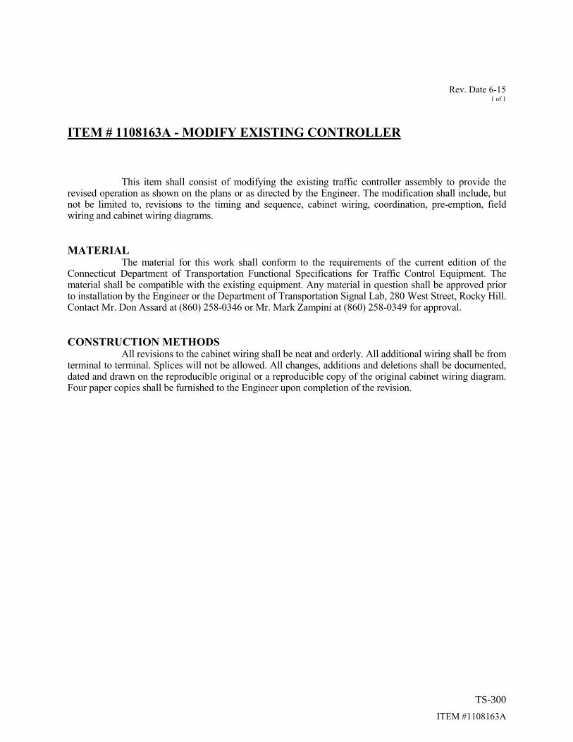
Rev. Date 6-15 1 of 1
ITEM #1108163A
ITEM # 1108163A - MODIFY EXISTING CONTROLLER
This item shall consist of modifying the existing traffic controller assembly to provide the revised operation as shown on the plans or as directed by the Engineer. The modification shall include, but not be limited to, revisions to the timing and sequence, cabinet wiring, coordination, pre-emption, field wiring and cabinet wiring diagrams.
MATERIAL
The material for this work shall conform to the requirements of the current edition of the Connecticut Department of Transportation Functional Specifications for Traffic Control Equipment. The material shall be compatible with the existing equipment. Any material in question shall be approved prior to installation by the Engineer or the Department of Transportation Signal Lab, 280 West Street, Rocky Hill. Contact Mr. Don Assard at (860) 258-0346 or Mr. Mark Zampini at (860) 258-0349 for approval.
CONSTRUCTION METHODS
All revisions to the cabinet wiring shall be neat and orderly. All additional wiring shall be from terminal to terminal. Splices will not be allowed. All changes, additions and deletions shall be documented, dated and drawn on the reproducible original or a reproducible copy of the original cabinet wiring diagram. Four paper copies shall be furnished to the Engineer upon completion of the revision.
TS-300

Rev. Date 4-12 1 of 3
ITEM #1118012A
ITEM#1118012A REMOVAL AND/OR RELOCATION OF TRAFFIC
SIGNAL EQUIPMENT
Section 11.18: Replace the entire section with the following: 11.18.01 – Description:
Remove all abandon traffic signal equipment. Restore the affected area. Where indicated
on the plans remove and reinstall existing traffic signal equipment to the location(s) shown. 11.18.02 – Materials:
The related sections of the following specifications apply to all incidental and additional material required for the proper relocation of existing equipment and the restoration of any area affected by this work.
• Division III, “Materials Section” of the Standard Specifications.
• Current Supplemental Specifications to the Standard Specifications.
• Applicable Special Provisions to the Standard Specifications.
• Current Department of Transportation, Functional Specifications for Traffic Control Equipment.
Article 11.18.03 - Construction Methods:
Schedule/coordinate the removal and/or relocation of existing traffic signal equipment with the installation of new equipment to maintain uninterrupted traffic signal control. This includes but is not limited to vehicle signals and detectors, pedestrian signals and pushbuttons, co-ordination, and pre-emption.
Abandoned Equipment
The contract traffic signal plan usually does not show existing equipment that will be abandoned. Consult the existing traffic signal plan for the location of abandoned material especially messenger strand, conduit risers, and handholes that are a distance from the intersection. A copy of the existing plan is usually in the existing controller cabinet. If not, a plan is available from the Division of Traffic Engineering upon request.
Unless shown on the plans it is not necessary to remove abandoned conduit in-trench and
conduit under-roadway When a traffic signal support strand, rigid metal conduit, down guy, or other traffic signal
equipment is attached to a utility pole, secure from the pole custodian permission to work on the pole. All applicable Public Utility Regulatory Authority (PURA) regulations and utility company requirements govern. Keep utility company apprised of the schedule and the nature of the work.
TS-301

Rev. Date 4-12 2 of 3
ITEM #1118012A
Remove all abandoned hardware, conduit risers, and down guys, Remove anchor rods, to 6” (150mm) below grade.
When underground material is removed, backfill the excavation with clean fill material. Compact the fill to eliminate settling. Remove entirely the following material: pedestal foundation; controller foundation; handhole; pressure sensitive vehicle detector complete with concrete base. Unless otherwise shown on the plan, remove steel pole and mast arm foundation to a depth of 2 feet (600mm) below grade. Restore the excavated area to a grade and condition compatible with the surrounding area.
• If in an unpaved area apply topsoil and establish turf in accordance with Section 9.44 and Section 9.50 of the Standard Specifications.
• If in pavement or sidewalk, restore the excavated area in compliance with the applicable
Sections of Division II, “Construction Details” of the Standard Specifications.
Relocated Equipment
In the presence of the Engineer, verify the condition of all material that will be relocated and reused at the site. Carefully remove all material, fittings, and attachments in a manner to safeguard parts from damage or loss. Replace at no additional cost, all material which becomes damaged or lost during removal, storage, or reinstallation.
Salvage Equipment
Salvage Material Stock No. Value
Aluminum Pedestal
8 foot (2.4 m)
330-16-7108
$ 100.00
All material not listed as salvage becomes the property of the Contractor. Properly handle, transport, then dispose in a suitable dump or recycle this material. Comply with all Federal and State hazardous waste laws and regulations.
In the presence of the Engineer, verify the condition and quantity of salvage material prior
to removal. After removal transport and store the material protected from moisture, dirt, and other damage. Coil and secure copper cable separate from other cable such as galvanized support strand.
Within 4 working days of removal, return the State owned salvage material to the
Department of Transportation Stores warehouse listed below. Supply all necessary manpower and equipment to load, transport, and unload the material. The condition and quantity of the material after unloading will be verified by the Engineer.
DOT Salvage Store #134 660 Brook Street
TS-302

Rev. Date 4-12 3 of 3
ITEM #1118012A
Rocky Hill, CT
Contact Materials Management Salvage Coordinator, at (860) 258-1980, at least 24 hours prior to delivery.
Municipal Owned Traffic Signal Equipment Return all municipal owned material such as pre-emption equipment to the Town.
TS-303

Rev. Date 3-161 of 1
GENERAL
NOTICE TO CONTRACTOR – SPECIAL PROVISIONS
The Contractor is hereby notified that Traffic Engineering’s Special Provisions pertaining to traffic signal equipment have been revised.
The contractor should note the changes in the following special provisions:Section 1.05 – Control of Work:
Product data sheet submission contact has changed.Section 1.08 – Prosecution and Progress-Construction w/ Closed Loop & Overlay:
Revised the number of days to contact the Traffic Signal Lab prior to work beginning.1107011A – Accessible Pedestrian Signal and Detector (Type):
Revised Basis of Payment to include “all necessary cable”.11xxxxxA – Video Detection System:
Extension Bracket – clarified attachment to span pole location.
NOTICE TO CONTRACTOR – UTILITY COMPANIES
It is understood that any references in the contract documents to Northeast Utilities, CL&P and/or Yankee Gas are meant to refer to Eversource.It is understood that any references in the contract documents to AT&T is meant to refer to Frontier Communications.
NOTICE TO CONTRACTOR – STANDARD SHEETS
The Contractor is hereby notified that Traffic Engineering’s Standard Sheets pertaining to traffic signal equipment have been revised.
The contractor should note the changes on the following sheets:
TR-1105_01 – Removed Strain Insulator.TR-1114_01 – Revised Span Wire to Wood Pole Details,
Added Bonding Attachment Details, Removed Anchor Details.
NOTICE TO CONTRACTOR – TURF ESTABLISHMENT - LAWN
The Contractor shall use turf seed mix that conforms to Article M.13.04. Refer to the special provisions contained elsewhere in this Contract.
TS-304

Rev. Date 5-161 of 1
GENERAL
SECTION 1.05 - CONTROL OF THE WORK
Article 1.05.02 - Plans, Working Drawings and Shop Drawingsis supplemented as follows:
Subarticle 1.05.02 - (2) is supplemented by the following:
Traffic Signal Items:
When required by the contract documents or when ordered by the Engineer, The Contractor shall prepare and submit product data sheets, working drawings and/or shop drawings for all traffic signal items, except Steel Span Poles and Mast Arm Assemblies when applicable, to the Division of Traffic Engineering for approval before fabrication. The packaged set of product data sheets, working drawings and/or shop drawings shall be submitted either in paper (hard copy) form or in an electronic portable document format (.pdf). The package submitted in paper form shall include one (1) set. Product data sheets shall be printed on ANSI A (8 ½” x 11”; 216 mm x 279mm; letter) sheets. Working drawings and shop drawings shall be printed on ANSI B (11” x 17”; 279 mm x 432 mm; ledger/tabloid) sheets.
Please mail to:
Traffic Electrical – Room 4307
Connecticut Department of TransportationDivision of Traffic Engineering – Electrical2800 Berlin TurnpikeP.O. Box 317546Newington, Connecticut 06131-7546
(860) 594-2791
The packaged set submitted in an electronic portable document format (.pdf) shall be in an individual file with appropriate bookmarks for each item. The electronic files for product data sheets shall be created on ANSI A (8 ½” x 11”; 216 mm x 279mm; letter) sheets. Working drawings and shop drawings shall be created on ANSI B (11” x 17”; 279 mm x 432 mm; ledger/tabloid) sheets.
Please send the pdf documents via email to:
TS-305

Rev. Date 5-161 of 1
GENERAL
SECTION 1.06 CONTROL OF MATERIALS
Article 1.06.01 - Source of Supply and Quality:
Add the following:
Traffic Signal Items:
For the following traffic signal items the contractor shall submit a complete description of the item, working drawings, product data sheets and other descriptive literature which completely illustrates such items presented for formal approval. Such approval shall not change the requirements for a certified test report and materials certificate as may be called for. All documents shall be submitted at one time, unless otherwise approved by the engineer.
Aluminum PedestalsRigid Metal Conduit
Traffic Signal Housings and Hardware
LED Traffic Signal Lamp UnitPedestrian Signals Housing and HardwarePedestrian Pushbuttons and Type of Sign
Loop Vehicle DetectionLoop DetectorLoop SealantLoop WireLoop Lead-in Wire
Control Cable
SECTION 1.06 CONTROL OF MATERIALS
Article 1.06.07 - Certified Test Reports and Materials Certificate.
Add the following:
1) For the materials in the following traffic signal items, a Certified Test Report will be required confirming their conformance to the requirements set forth in these plans or specifications or both. Should the consignee noted on a Certified Test Report be other than the Prime Contractor, then Materials Certificates shall be required to identify the shipment.
N/A
2) For the materials in the following traffic signal items, a Materials Certificate will be required confirming their conformance to the requirements set forth in these plans or specifications or both.
Concrete HandholeAluminum Pedestals
TS-306

Rev. Date 5-161 of 1
GENERAL
SECTION 1.07 - LEGAL RELATIONS AND RESPONSIBILITIES
Article 1.07.13 - Contractor's Responsibility for Adjacent Property, Facilities and Services is supplemented as follows:
The following company and representative shall be contacted by the Contractor to coordinate the protection of their utilities on this project 30 days prior to the start of any work on this project involving their utilities:
Mr. Augusto GrazunaDistrict 1 Electrical SupervisorDepartment of TransportationHartford, Connecticut(860) 566-3156/[email protected]
Mr. Vasant PatelConnecticut Natural Gas76 Meadow Street, 1st FloorEast Hartford, CT 06108(860) [email protected]
Mr. Tom DerwayCox Communications, Inc.801 Parker StreetManchester, CT 06042(860) [email protected]
Mr. Patrick KearneyWater Department Administrator125 Spring Street, P.O. Box 191Manchester, CT 06045-0191(860) [email protected]
Mr. Raymond PuzemisFrontier Communications1441 North Colony Rd Meriden, CT 06045-4101(203) [email protected]
Mr. Barry LashleyEversource Energy135 New Road, MADISON AWCMadison, CT 06443(203) [email protected]
TS-307

Rev. Date 3-161 of 1
GENERAL
SECTION 1.08 - PROSECUTION AND PROGRESS
Article 1.08.03 - Prosecution of Work:
Add the following:The Contractor will not be allowed to install traffic signal or pedestrian heads until the controllers are on hand and ready for installation. Once installation of this equipment commences, the Contractor shall complete this work in a most expeditious manner.
The Contractor shall notify the project engineer on construction projects, or the district permit agent on permit jobs, when all traffic signal work is completed. This will include all work at signalized intersections including loop replacements, adjusting existing traffic signals or any relocation work including handholes. The project engineer or district permit agent will notify the Division of Traffic Engineering to coordinate a field inspection of all work. Refer to Section 10.00 – General Clauses for Highway Illumination and Traffic Signal Projects, Article 10.00.10 and corresponding special provision.
TS-308

Rev. Date 1-141 of 1
GENERAL
SECTION 10.00 - GENERAL CLAUSES FOR HIGHWAY ILLUMINATION AND TRAFFIC SIGNAL PROJECTS
Article 10.00.10 Section 3. Functional Inspection, first paragraph after the 2nd sentence: Add the following:
The contractor shall have a bucket truck with crew on site during the Functional Inspection to make any necessary aerial signal adjustments as directed by the Engineer.
Article 10.00.12 - Negotiations with utility company: Add the following:
The contractor shall give notice to utility companies a minimum of 30 days prior to required work or services to the utility company. Refer to Section 1.07 – Legal Relations and Responsibilities for the list of utility companies and representatives the contractor shall use.
The Contractor shall perform all work in conformance with Rules and Regulations of Public Utility Regulatory Authority (PURA) concerning Traffic Signals attached to Public Service Company Poles. The Contractor is cautioned that there may be energized wires in the vicinity of the specified installations. In addition to ensuring compliance with NESC and OSHA regulations, the Contractor and/or its Sub-Contractors shall coordinate with the appropriate utility company for securing/protecting the site during the installation of traffic signal mast arms, span poles or illumination poles.
When a span is attached to a utility pole, the Contractor shall ensure the anchor is in line with the proposed traffic signal span wire. More than 5 degree deviation will lower the holding strength and is not allowed. The Contractor shall provide any necessary assistance required by the utility company, and ensure the anchor and guy have been installed and properly tensioned prior to attaching the span wire to the utility pole.
TS-309
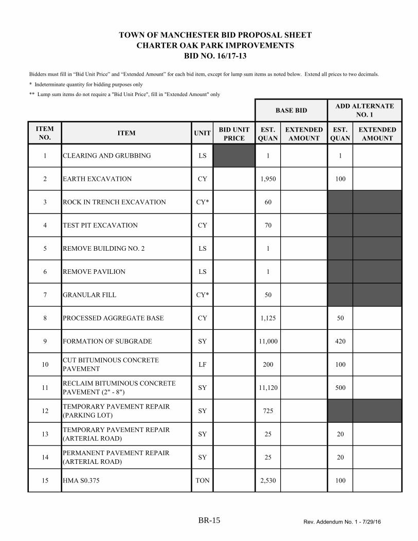
* Indeterminate quantity for bidding purposes only
** Lump sum items do not require a "Bid Unit Price", fill in "Extended Amount" only
ITEM
NO.ITEM UNIT
BID UNIT
PRICE
EST.
QUAN
EXTENDED
AMOUNT
EST.
QUAN
EXTENDED
AMOUNT
1 CLEARING AND GRUBBING LS 1 1
2 EARTH EXCAVATION CY 1,950 100
3 ROCK IN TRENCH EXCAVATION CY* 60
4 TEST PIT EXCAVATION CY 70
5 REMOVE BUILDING NO. 2 LS 1
6 REMOVE PAVILION LS 1
7 GRANULAR FILL CY* 50
8 PROCESSED AGGREGATE BASE CY 1,125 50
9 FORMATION OF SUBGRADE SY 11,000 420
10CUT BITUMINOUS CONCRETE
PAVEMENTLF 200 100
11RECLAIM BITUMINOUS CONCRETE
PAVEMENT (2" - 8")SY 11,120 500
12TEMPORARY PAVEMENT REPAIR
(PARKING LOT)SY 725
13TEMPORARY PAVEMENT REPAIR
(ARTERIAL ROAD)SY 25 20
14PERMANENT PAVEMENT REPAIR
(ARTERIAL ROAD)SY 25 20
15 HMA S0.375 TON 2,530 100
BID NO. 16/17-13
Bidders must fill in “Bid Unit Price” and “Extended Amount” for each bid item, except for lump sum items as noted below. Extend all prices to two decimals.
TOWN OF MANCHESTER BID PROPOSAL SHEET
CHARTER OAK PARK IMPROVEMENTS
BASE BIDADD ALTERNATE
NO. 1
Rev. Addendum No. 1 - 7/29/16BR-15

* Indeterminate quantity for bidding purposes only
** Lump sum items do not require a "Bid Unit Price", fill in "Extended Amount" only
ITEM
NO.ITEM UNIT
BID UNIT
PRICE
EST.
QUAN
EXTENDED
AMOUNT
EST.
QUAN
EXTENDED
AMOUNT
BID NO. 16/17-13
Bidders must fill in “Bid Unit Price” and “Extended Amount” for each bid item, except for lump sum items as noted below. Extend all prices to two decimals.
TOWN OF MANCHESTER BID PROPOSAL SHEET
CHARTER OAK PARK IMPROVEMENTS
BASE BIDADD ALTERNATE
NO. 1
16 HMA S0.5 TON 80
17 4" CONCRETE SIDEWALK SF* 50
18 5" CONCRETE SIDEWALK SF 560 95
195" CONCRETE SIDEWALK AND CURB
MONOLITHICSF 710 490
206" REINFORCED CONCRETE SIDEWALK
WITH CURB MONOLITHICSF 280
21 6" CONCRETE SIDEWALK RAMP SF 880
22 8" CONCRETE SIDEWALK RAMP SF 280 160
23 REMOVE CONCRETE SIDEWALK SY 185
24 BITUMINOUS CONCRETE SIDEWALK SY 2,300 30
25BITUMINOUS CONCRETE SIDEWALK
(4" THICK)SY 130
26 6" CONCRETE DRIVEWAY APRON SF 350
27 BITUMINOUS CONCRETE DRIVEWAY SY 175
28 BITUMINOUS CONCRETE LIP CURB LF 500
29 6" EXTRUDED CONCRETE CURB LF 3,570 130
30 GRANITE STONE CURB LF* 10
Rev. Addendum No. 1 - 7/29/16BR-16

* Indeterminate quantity for bidding purposes only
** Lump sum items do not require a "Bid Unit Price", fill in "Extended Amount" only
ITEM
NO.ITEM UNIT
BID UNIT
PRICE
EST.
QUAN
EXTENDED
AMOUNT
EST.
QUAN
EXTENDED
AMOUNT
BID NO. 16/17-13
Bidders must fill in “Bid Unit Price” and “Extended Amount” for each bid item, except for lump sum items as noted below. Extend all prices to two decimals.
TOWN OF MANCHESTER BID PROPOSAL SHEET
CHARTER OAK PARK IMPROVEMENTS
BASE BIDADD ALTERNATE
NO. 1
31 RADIUS GRANITE STONE CURB LF 55
32 MISCELLANEOUS CONCRETE CY 10
33 REMOVE MISCELLANEOUS CONCRETE CY* 5 25
34 TIMBER RAIL LF 680 215
35WOODEN STOCKADE FENCE WITH
STEEL POSTS (6' HIGH)LF 40
36DUMPSTER GATE WITH STEEL POSTS
(2 PANEL, 18' TOTAL WIDTH, 6' HIGH)EA 1
37 12" R.C.P. (CLASS V) LF 70
38 15" R.C.P. (CLASS V) LF 30
39 12" HDPE LF 140
40 15" HDPE LF 35
41 PLUG PIPE EA 17
42 ABANDON PIPE WITH FLOWABLE FILL LF 1,600
43 REMOVE PIPE LF 70
44TYPE "C" CATCH BASIN WITH
CONCRETE CURB INLETEA 8
45
TYPE "C" DOUBLE GRATE TYPE I
CATCH BASIN WITH CONCRETE CURB
INLET
EA 2
Rev. Addendum No. 1 - 7/29/16BR-17

* Indeterminate quantity for bidding purposes only
** Lump sum items do not require a "Bid Unit Price", fill in "Extended Amount" only
ITEM
NO.ITEM UNIT
BID UNIT
PRICE
EST.
QUAN
EXTENDED
AMOUNT
EST.
QUAN
EXTENDED
AMOUNT
BID NO. 16/17-13
Bidders must fill in “Bid Unit Price” and “Extended Amount” for each bid item, except for lump sum items as noted below. Extend all prices to two decimals.
TOWN OF MANCHESTER BID PROPOSAL SHEET
CHARTER OAK PARK IMPROVEMENTS
BASE BIDADD ALTERNATE
NO. 1
46
TYPE "C" DOUBLE GRATE TYPE II
CATCH BASIN WITH CONCRETE CURB
INLET
EA 2
47
RESET TYPE "C" CATCH BASIN TOP
WITH CONCRETE CURB INLET (NEW
TOP)
EA 1
48RESET TYPE "C-L" CATCH BASIN TOP
(EXISTING TOP)EA 1
49 CONVERT CATCH BASIN TO MANHOLE EA 7
50CONVERT CATCH BASIN TO YARD
DRAINEA 2
51CONVERT MANHOLE TO CATCH BASIN
(3-SIDED TOP)EA 1
52 REMOVE DRAINAGE STRUCTURE EA 3
53 ABANDON DRAINAGE STRUCTURE EA* 1
54RESET MANHOLE TO GRADE
(EXISTING FRAME AND COVER)EA 2 2
55RESET MANHOLE TO GRADE (NEW
FRAME AND COVER)EA* 1
56 HYDRODYNAMIC SEPARATOR EA 2
57 1" COPPER SAMPLING LINE EA 1
58 2" COPPER SERVICE EA 2
59 ABANDON WATER SERVICE EA 4
60 8" CLDIP WATER MAIN LF 300
Rev. Addendum No. 1 - 7/29/16BR-18

* Indeterminate quantity for bidding purposes only
** Lump sum items do not require a "Bid Unit Price", fill in "Extended Amount" only
ITEM
NO.ITEM UNIT
BID UNIT
PRICE
EST.
QUAN
EXTENDED
AMOUNT
EST.
QUAN
EXTENDED
AMOUNT
BID NO. 16/17-13
Bidders must fill in “Bid Unit Price” and “Extended Amount” for each bid item, except for lump sum items as noted below. Extend all prices to two decimals.
TOWN OF MANCHESTER BID PROPOSAL SHEET
CHARTER OAK PARK IMPROVEMENTS
BASE BIDADD ALTERNATE
NO. 1
61 12" CLDIP WATER MAIN LF 25
62 16" CLDIP WATER MAIN LF 570
62A 6" GATE VALVE EA 1
63 8" GATE VALVE EA 3
64 12" GATE VALVE EA 1
65 8" - 1/8 DUCTILE IRON BEND EA 2
66 8" - 1/32 DUCTILE IRON BEND EA 2
67 12" - 1/8 DUCTILE IRON BEND EA 1
68 16" - 1/8 DUCTILE IRON BEND EA 8
69 12" X 6" DI TEE EA 1
70 12" X 8" DI TEE EA 1
71 16" X 8" DI REDUCER EA 2
72 PUMP STATION RETROFIT EA 1
73 POST HYDRANT ASSEMBLY EA 1
75 8" PVC SANITARY SEWER (0'-10' DEEP) LF 380
Rev. Addendum No. 1 - 7/29/16BR-19
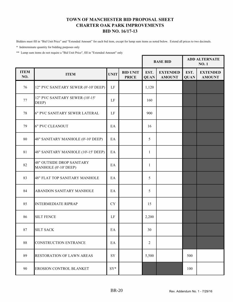
* Indeterminate quantity for bidding purposes only
** Lump sum items do not require a "Bid Unit Price", fill in "Extended Amount" only
ITEM
NO.ITEM UNIT
BID UNIT
PRICE
EST.
QUAN
EXTENDED
AMOUNT
EST.
QUAN
EXTENDED
AMOUNT
BID NO. 16/17-13
Bidders must fill in “Bid Unit Price” and “Extended Amount” for each bid item, except for lump sum items as noted below. Extend all prices to two decimals.
TOWN OF MANCHESTER BID PROPOSAL SHEET
CHARTER OAK PARK IMPROVEMENTS
BASE BIDADD ALTERNATE
NO. 1
76 12" PVC SANITARY SEWER (0'-10' DEEP) LF 1,120
7712" PVC SANITARY SEWER (10'-15'
DEEP)LF 160
78 6" PVC SANITARY SEWER LATERAL LF 900
79 6" PVC CLEANOUT EA 16
80 48" SANITARY MANHOLE (0'-10' DEEP) EA 5
81 48" SANITARY MANHOLE (10'-15' DEEP) EA 1
8248" OUTSIDE DROP SANITARY
MANHOLE (0'-10' DEEP)EA 1
83 48" FLAT TOP SANITARY MANHOLE EA 5
84 ABANDON SANITARY MANHOLE EA 5
85 INTERMEDIATE RIPRAP CY 15
86 SILT FENCE LF 2,200
87 SILT SACK EA 30
88 CONSTRUCTION ENTRANCE EA 2
89 RESTORATION OF LAWN AREAS SY 5,500 500
90 EROSION CONTROL BLANKET SY* 100
Rev. Addendum No. 1 - 7/29/16BR-20

* Indeterminate quantity for bidding purposes only
** Lump sum items do not require a "Bid Unit Price", fill in "Extended Amount" only
ITEM
NO.ITEM UNIT
BID UNIT
PRICE
EST.
QUAN
EXTENDED
AMOUNT
EST.
QUAN
EXTENDED
AMOUNT
BID NO. 16/17-13
Bidders must fill in “Bid Unit Price” and “Extended Amount” for each bid item, except for lump sum items as noted below. Extend all prices to two decimals.
TOWN OF MANCHESTER BID PROPOSAL SHEET
CHARTER OAK PARK IMPROVEMENTS
BASE BIDADD ALTERNATE
NO. 1
914" YELLOW EPOXY RESIN PAVEMENT
MARKINGSLF 830 250
924" WHITE EPOXY RESIN PAVEMENT
MARKINGSLF 5,100
93EPOXY RESIN PAVEMENT MARKINGS,
SYMBOLS AND LEGENDSSF* 700 200
94 HANDICAP PARKING SYMBOL EA 7
95MAINTENANCE AND PROTECTION OF
TRAFFIC LS 1 1
96 UNIFORMED POLICE OFFICERS EST EST $1,000.00
97 CONSTRUCTION AREA SIGNS SF* 50
98 CONSTRUCTION STAKING LS 1 1
99 SITE LIGHTING LS 1
100 MODIFY TRAFFIC SIGNAL LS 1
BASE BID TOTAL:
ADD ALTERNATE
NO. 1 TOTAL:
Rev. Addendum No. 1 - 7/29/16BR-21
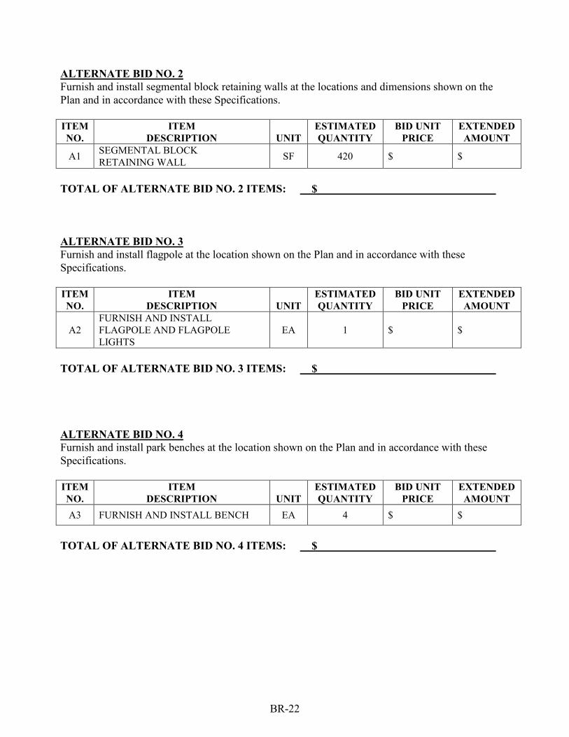
BR-22
ALTERNATE BID NO. 2 Furnish and install segmental block retaining walls at the locations and dimensions shown on the
Plan and in accordance with these Specifications.
ITEM
NO.
ITEM
DESCRIPTION
UNIT
ESTIMATED
QUANTITY
BID UNIT
PRICE
EXTENDED
AMOUNT
A1 SEGMENTAL BLOCK
RETAINING WALL SF 420 $ $
TOTAL OF ALTERNATE BID NO. 2 ITEMS: $
ALTERNATE BID NO. 3 Furnish and install flagpole at the location shown on the Plan and in accordance with these
Specifications.
ITEM
NO.
ITEM
DESCRIPTION
UNIT
ESTIMATED
QUANTITY
BID UNIT
PRICE
EXTENDED
AMOUNT
A2
FURNISH AND INSTALL
FLAGPOLE AND FLAGPOLE
LIGHTS
EA 1 $ $
TOTAL OF ALTERNATE BID NO. 3 ITEMS: $
ALTERNATE BID NO. 4 Furnish and install park benches at the location shown on the Plan and in accordance with these
Specifications.
ITEM
NO.
ITEM
DESCRIPTION
UNIT
ESTIMATED
QUANTITY
BID UNIT
PRICE
EXTENDED
AMOUNT
A3 FURNISH AND INSTALL BENCH EA 4 $ $
TOTAL OF ALTERNATE BID NO. 4 ITEMS: $

BR-23
A. The undersigned understands that there may be changes, omissions, or modification in the
work, and that appropriate adjustments will be made to the Contract price in accordance with
the Contract Documents. The undersigned understands that the Owner reserves the right to
accept or reject any or all bids, and to waive all formalities, any irregularities, and accept the
Bid deemed to be in the Owner's best interest.
B. Bid prices shall not include any sales, excise or other taxes for which the Owner is not liable. Town of Manchester is the awarding authority. The bid award is anticipated in AUGUST
2016. The Bidder agrees to hold the above pricing for sixty (60) days.
C. The Bid security in the sum of: 5% OF TOTAL BID is to become the property of the
Town in the event the above forms are not executed within the time set forth above, as
liquidated damages, and not as a penalty for the delay and additional expense to the Town
caused thereby.
D. The Town reserves the right to award the base bid or the base bid plus any combination of
the alternate bids.
Respectfully Submitted By: (Signature)
Name (Please Print):
Title:
SEAL Company: (If Bid is by a Corporation) Business Address:
Business Phone: ( )
Business Fax: ( )
Email Address:

TOWN OF MANCHESTERP U B L I C W O R K S D E P A R T M E N T
E N G I N E E R I N G D I V I S I O N
CHARTER OAK PARK IMPROVEMENTS50 CHARTER OAK STREET
JULY 2016
PROJECT LOCATION
PROJECT AREA
R:\P
roje
ct\P
ublic
Wor
ks\2
0130
93 -
Cha
rter O
ak P
ark
Infr
astru
ctur
e Im
prov
emen
ts\P
roj\_
As-
Bid
\201
3093
BID
-Cov
er-R
ev 0
7-27
-16.
dwg,
7/2
8/20
16 2
:38:
36 P
M, m
hand
field

SF
R:\P
roje
ct\P
ublic
Wor
ks\2
0130
93 -
Cha
rter O
ak P
ark
Infr
astru
ctur
e Im
prov
emen
ts\P
roj\_
As-
Bid
\201
3093
BID
-Pla
n-R
ev 0
7-27
-16.
dwg,
7/2
9/20
16 1
1:45
:26
AM
, mha
ndfie
ld

SF
R:\P
roje
ct\P
ublic
Wor
ks\2
0130
93 -
Cha
rter O
ak P
ark
Infr
astru
ctur
e Im
prov
emen
ts\P
roj\_
As-
Bid
\201
3093
BID
-Pla
n-R
ev 0
7-27
-16.
dwg,
7/2
9/20
16 1
1:29
:48
AM
, mha
ndfie
ld

MAT
CHLI
NE -
SEE
SHEE
T 11
SF
MATCHLINE - SEE SHEET 12
R:\P
roje
ct\P
ublic
Wor
ks\2
0130
93 -
Cha
rter O
ak P
ark
Infr
astru
ctur
e Im
prov
emen
ts\P
roj\_
As-
Bid
\201
3093
BID
-Pla
n-R
ev 0
7-27
-16.
dwg,
7/2
9/20
16 1
1:32
:20
AM
, mha
ndfie
ld

MAT
CHLI
NE -
SEE
SHEE
T 10
SF
R:\P
roje
ct\P
ublic
Wor
ks\2
0130
93 -
Cha
rter O
ak P
ark
Infr
astru
ctur
e Im
prov
emen
ts\P
roj\_
As-
Bid
\201
3093
BID
-Pla
n-R
ev 0
7-27
-16.
dwg,
7/2
9/20
16 1
1:44
:42
AM
, mha
ndfie
ld

MAT
CHLI
NE -
SEE
SHEE
T 13
SF
MATCHLINE - SEE SHEET 10
R:\P
roje
ct\P
ublic
Wor
ks\2
0130
93 -
Cha
rter O
ak P
ark
Infr
astru
ctur
e Im
prov
emen
ts\P
roj\_
As-
Bid
\201
3093
BID
-Pla
n-R
ev 0
7-27
-16.
dwg,
7/2
9/20
16 1
1:44
:14
AM
, mha
ndfie
ld

MATCHLINE STA 5+
00 - SEE SHEET 16
SF
R:\P
roje
ct\P
ublic
Wor
ks\2
0130
93 -
Cha
rter O
ak P
ark
Infr
astru
ctur
e Im
prov
emen
ts\P
roj\_
As-
Bid
\201
3093
BID
-Pla
n_SA
NIT
AR
Y-R
ev 0
7-27
-16.
dwg,
7/2
9/20
16 1
1:00
:18
AM
, bka
lans
uriy
a

SF
R:\P
roje
ct\P
ublic
Wor
ks\2
0130
93 -
Cha
rter O
ak P
ark
Infr
astru
ctur
e Im
prov
emen
ts\P
roj\_
As-
Bid
\201
3093
BID
-Pla
n_SA
NIT
AR
Y-R
ev 0
7-27
-16.
dwg,
7/2
9/20
16 1
1:01
:11
AM
, bka
lans
uriy
a

MAT
CHLI
NE S
TA 1
0+25
- SE
E SH
EET
17
SF
MATCHLINE STA 5+
00 - SEE SHEET 14
R:\P
roje
ct\P
ublic
Wor
ks\2
0130
93 -
Cha
rter O
ak P
ark
Infr
astru
ctur
e Im
prov
emen
ts\P
roj\_
As-
Bid
\201
3093
BID
-Pla
n_SA
NIT
AR
Y-R
ev 0
7-27
-16.
dwg,
7/2
9/20
16 1
1:06
:34
AM
, bka
lans
uriy
a

SF
MATCHLINE STA 10+
25 - SEE SHEET 16
R:\P
roje
ct\P
ublic
Wor
ks\2
0130
93 -
Cha
rter O
ak P
ark
Infr
astru
ctur
e Im
prov
emen
ts\P
roj\_
As-
Bid
\201
3093
BID
-Pla
n_SA
NIT
AR
Y-R
ev 0
7-27
-16.
dwg,
7/2
9/20
16 1
1:07
:11
AM
, bka
lans
uriy
a

SF
R:\P
roje
ct\P
ublic
Wor
ks\2
0130
93 -
Cha
rter O
ak P
ark
Infr
astru
ctur
e Im
prov
emen
ts\P
roj\_
As-
Bid
\201
3093
BID
-Pla
n-R
ev 0
7-27
-16.
dwg,
7/2
9/20
16 1
1:47
:02
AM
, mha
ndfie
ld

PUMP STATION RETROFIT1"=5'
SF
48" OUTSIDE DROP SANITARY MANHOLEN O T T O S C A L E
48" DOGHOUSE MANHOLEN O T T O S C A L E
POST HYDRANT ASSEMBLYN O T T O S C A L E
R:\P
roje
ct\P
ublic
Wor
ks\2
0130
93 -
Cha
rter O
ak P
ark
Infr
astru
ctur
e Im
prov
emen
ts\P
roj\_
As-
Bid
\201
3093
BID
-Det
ails
-Rev
07-
27-1
6.dw
g, 7
/29/
2016
3:4
4:58
PM
, bka
lans
uriy
a
