charging system
DESCRIPTION
2005-2008 Acura RLTRANSCRIPT

2005-08 ELECTRICAL
Charging System - RL
COMPONENT LOCATION INDEX
Fig. 1: Identifying Charging System Components Location Courtesy of AMERICAN HONDA MOTOR CO., INC.
SYMPTOM TROUBLESHOOTING INDEX
SYMPTOM TROUBLESHOOTING INDEX Symptom Diagnostic procedure
Charging system indicator does not come on with the ignition switch ON (II),
Troubleshoot the charging system indicator circuit (see CHARGING SYSTEM INDICATOR CIRCUIT TROUBLESHOOTING ).
Charging system indicator stays on
2007 Acura RL
2005-08 ELECTRICAL Charging System - RL
2007 Acura RL
2005-08 ELECTRICAL Charging System - RL
me
Friday, June 05, 2009 2:41:57 PM Page 1 © 2005 Mitchell Repair Information Company, LLC.
me
Friday, June 05, 2009 2:42:02 PM Page 1 © 2005 Mitchell Repair Information Company, LLC.

CIRCUIT DIAGRAM
1. Check for PGM-FI DTCs.
2. Troubleshoot the charging system indicator circuit (see CHARGING SYSTEM INDICATOR CIRCUIT TROUBLESHOOTING ).
3. Check for a broken drive belt (see DRIVE BELT INSPECTION ).
4. Check the drive belt auto-tensioner (see DRIVE BELT AUTO-TENSIONER INSPECTION ).
Battery discharged 1. Check for excessive parasitic current draw with the ignition switch OFF, and the key removed. The multiplex control units may take up to 10 minutes to turn off (sleep mode) for some models.
2. Check for a broken drive belt (see DRIVE BELT INSPECTION ).
3. Check the drive belt auto-tensioner (see DRIVE BELT AUTO-TENSIONER INSPECTION ).
4. Troubleshoot the alternator and regulator circuit (see ALTERNATOR AND REGULATOR CIRCUIT TROUBLESHOOTING ).
5. Check for a poor connection at the battery terminal.
6. Test the battery (see BATTERY TEST ). Battery overcharged 1. Troubleshoot the alternator and regulator
circuit (see ALTERNATOR AND REGULATOR CIRCUIT TROUBLESHOOTING ).
2. Test the battery (see BATTERY TEST ).
2007 Acura RL
2005-08 ELECTRICAL Charging System - RL
me
Friday, June 05, 2009 2:41:57 PM Page 2 © 2005 Mitchell Repair Information Company, LLC.

Fig. 2: Charging System Circuit Diagram Courtesy of AMERICAN HONDA MOTOR CO., INC.
CHARGING SYSTEM INDICATOR CIRCUIT TROUBLESHOOTING
1. Turn the ignition switch ON (II).
Does the charging system indicator come on?
YES -Go to step 2.
NO -Go to step 11.
2007 Acura RL
2005-08 ELECTRICAL Charging System - RL
me
Friday, June 05, 2009 2:41:57 PM Page 3 © 2005 Mitchell Repair Information Company, LLC.
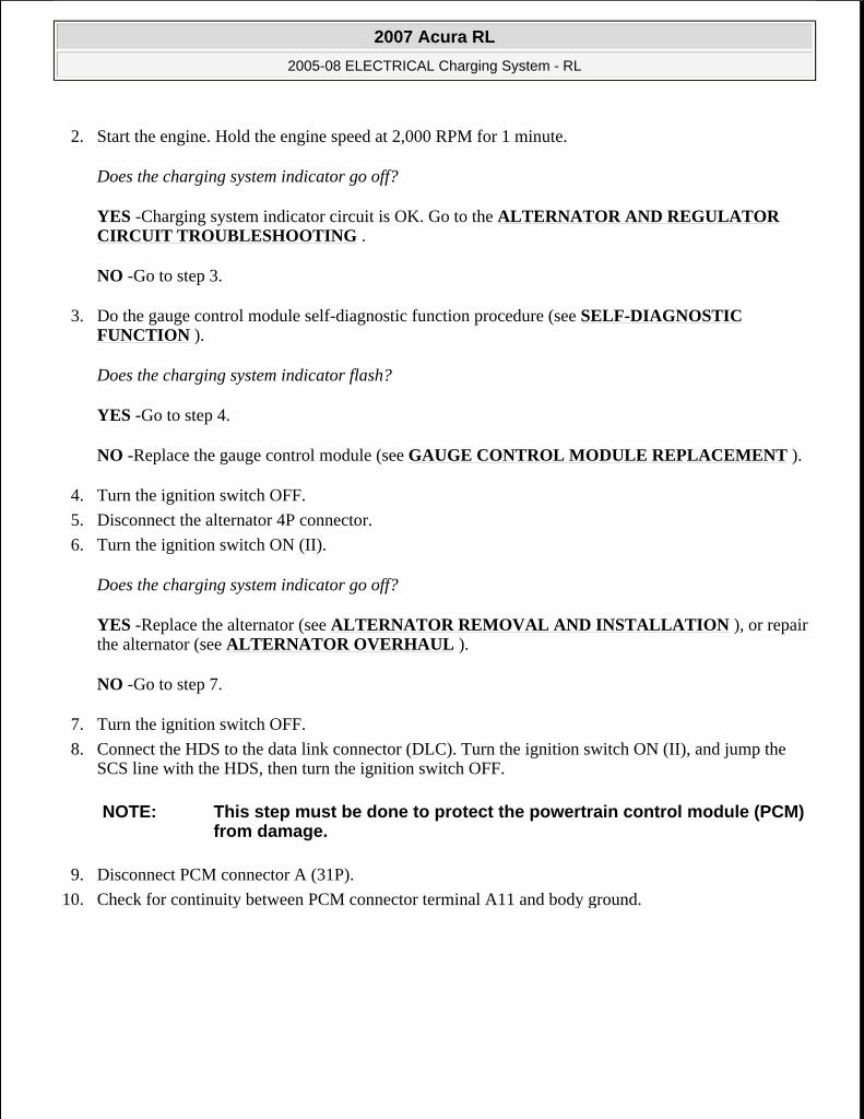
2. Start the engine. Hold the engine speed at 2,000 RPM for 1 minute.
Does the charging system indicator go off?
YES -Charging system indicator circuit is OK. Go to the ALTERNATOR AND REGULATOR CIRCUIT TROUBLESHOOTING .
NO -Go to step 3.
3. Do the gauge control module self-diagnostic function procedure (see SELF-DIAGNOSTIC FUNCTION ).
Does the charging system indicator flash?
YES -Go to step 4.
NO -Replace the gauge control module (see GAUGE CONTROL MODULE REPLACEMENT ).
4. Turn the ignition switch OFF.
5. Disconnect the alternator 4P connector.
6. Turn the ignition switch ON (II).
Does the charging system indicator go off?
YES -Replace the alternator (see ALTERNATOR REMOVAL AND INSTALLATION ), or repair the alternator (see ALTERNATOR OVERHAUL ).
NO -Go to step 7.
7. Turn the ignition switch OFF.
8. Connect the HDS to the data link connector (DLC). Turn the ignition switch ON (II), and jump the SCS line with the HDS, then turn the ignition switch OFF.
9. Disconnect PCM connector A (31P).
10. Check for continuity between PCM connector terminal A11 and body ground.
NOTE: This step must be done to protect the powertrain control module (PCM) from damage.
2007 Acura RL
2005-08 ELECTRICAL Charging System - RL
me
Friday, June 05, 2009 2:41:57 PM Page 4 © 2005 Mitchell Repair Information Company, LLC.

Fig. 3: Checking Continuity Between PCM Connector Terminal A11 And Body Ground Courtesy of AMERICAN HONDA MOTOR CO., INC.
Is there continuity?
YES -Repair short in the wire between the alternator and the PCM.
NO -Update the PCM if it does not have the latest software (see UPDATING THE PCM ), or substitute a known-good PCM (see SUBSTITUTING THE PCM ), then recheck. If the symptom/indication goes away with a known-good PCM, replace the original PCM (see SUBSTITUTING THE PCM ).
11. Do the gauge control module self-diagnostic function procedure (see SELF-DIAGNOSTIC FUNCTION ).
Does the charging system indicator flash?
YES -Go to step 12.
NO -Replace the gauge control module (see GAUGE CONTROL MODULE REPLACEMENT ).
12. Turn the ignition switch OFF.
13. Disconnect the alternator 4P connector.
14. Connect alternator 4P connector terminal No. 3 and body ground with a jumper wire.
Fig. 4: Connecting Alternator 4P Connector Terminal No 3 And Body Ground With Jumper Wire Courtesy of AMERICAN HONDA MOTOR CO., INC.
2007 Acura RL
2005-08 ELECTRICAL Charging System - RL
me
Friday, June 05, 2009 2:41:57 PM Page 5 © 2005 Mitchell Repair Information Company, LLC.
15. Turn the ignition switch ON (II).
Does the charging system indicator come on?
YES -Replace the alternator (see ALTERNATOR REMOVAL AND INSTALLATION ), or repair the alternator (see ALTERNATOR OVERHAUL ).
NO -Go to step 16.
16. Connect the HDS to the DLC. Turn the ignition switch ON (II), and jump the SCS line with the HDS, then turn the ignition switch OFF.
17. Disconnect PCM connector A (31P).
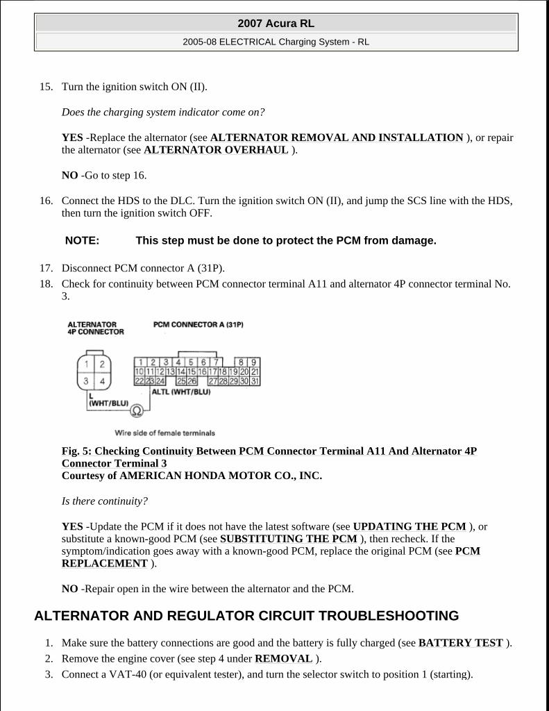
18. Check for continuity between PCM connector terminal A11 and alternator 4P connector terminal No. 3.
Fig. 5: Checking Continuity Between PCM Connector Terminal A11 And Alternator 4P Connector Terminal 3 Courtesy of AMERICAN HONDA MOTOR CO., INC.
Is there continuity?
YES -Update the PCM if it does not have the latest software (see UPDATING THE PCM ), or substitute a known-good PCM (see SUBSTITUTING THE PCM ), then recheck. If the symptom/indication goes away with a known-good PCM, replace the original PCM (see PCM REPLACEMENT ).
NO -Repair open in the wire between the alternator and the PCM.
ALTERNATOR AND REGULATOR CIRCUIT TROUBLESHOOTING
1. Make sure the battery connections are good and the battery is fully charged (see BATTERY TEST ).
2. Remove the engine cover (see step 4 under REMOVAL ).
3. Connect a VAT-40 (or equivalent tester), and turn the selector switch to position 1 (starting).
NOTE: This step must be done to protect the PCM from damage.
2007 Acura RL
2005-08 ELECTRICAL Charging System - RL
me
Friday, June 05, 2009 2:41:57 PM Page 6 © 2005 Mitchell Repair Information Company, LLC.

Fig. 6: Identifying VAT-40 Courtesy of AMERICAN HONDA MOTOR CO., INC.
4. Start the engine. Hold the engine speed at 3,000 RPM, with no load until the radiator fan comes on, then let it idle.
5. Raise the engine speed to 2,000 RPM, and hold it there.
Is the voltage over 15.1 V?
YES -Check the alternator mounting bolt torque. If they are loose, retorque them. If the bolts are tight, replace the alternator (see ALTERNATOR REMOVAL AND INSTALLATION ) or rear housing assembly (see ALTERNATOR OVERHAUL ).
NO -Go to step 6.
6. Release the accelerator pedal, and let the engine idle.
7. Turn off all the accessories. Select the charging test on the tester.
8. Remove the inductive pickup, and zero the ammeter.
9. Place the inductive pickup over the B terminal wire of the alternator so the arrow points away from the alternator.
10. Raise the engine speed to 2,000 RPM, and hold it there.
Is the voltage less than 13.5 V?
YES -Go to ALTERNATOR CONTROL CIRCUIT TROUBLESHOOTING .
NO -Go to step 11.
11. Apply a load with the VAT-40 until the battery voltage drops within 12-13.5 V.
2007 Acura RL
2005-08 ELECTRICAL Charging System - RL
me
Friday, June 05, 2009 2:41:57 PM Page 7 © 2005 Mitchell Repair Information Company, LLC.
Is the amperage 87.5 A or more?
YES -The charging system is OK.
NO -Replace the alternator (see ALTERNATOR REMOVAL AND INSTALLATION ), or repair the alternator (see ALTERNATOR OVERHAUL ).
ALTERNATOR CONTROL CIRCUIT TROUBLESHOOTING
1. Connect the HDS to the data link connector (DLC), and check for DTCs. If a DTC is present, diagnose and repair the cause before continuing with this test.
2. Disconnect the alternator 4P connector from the alternator.
3. Start the engine, and turn on the headlights to high beam.
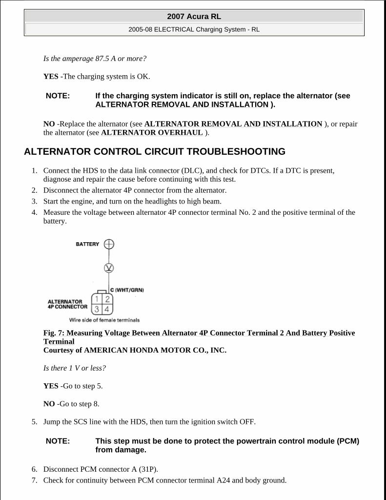
4. Measure the voltage between alternator 4P connector terminal No. 2 and the positive terminal of the battery.
Fig. 7: Measuring Voltage Between Alternator 4P Connector Terminal 2 And Battery Positive Terminal Courtesy of AMERICAN HONDA MOTOR CO., INC.
Is there 1 V or less?
YES -Go to step 5.
NO -Go to step 8.
5. Jump the SCS line with the HDS, then turn the ignition switch OFF.
6. Disconnect PCM connector A (31P).
7. Check for continuity between PCM connector terminal A24 and body ground.
NOTE: If the charging system indicator is still on, replace the alternator (see ALTERNATOR REMOVAL AND INSTALLATION ).
NOTE: This step must be done to protect the powertrain control module (PCM) from damage.
2007 Acura RL
2005-08 ELECTRICAL Charging System - RL
me
Friday, June 05, 2009 2:41:57 PM Page 8 © 2005 Mitchell Repair Information Company, LLC.
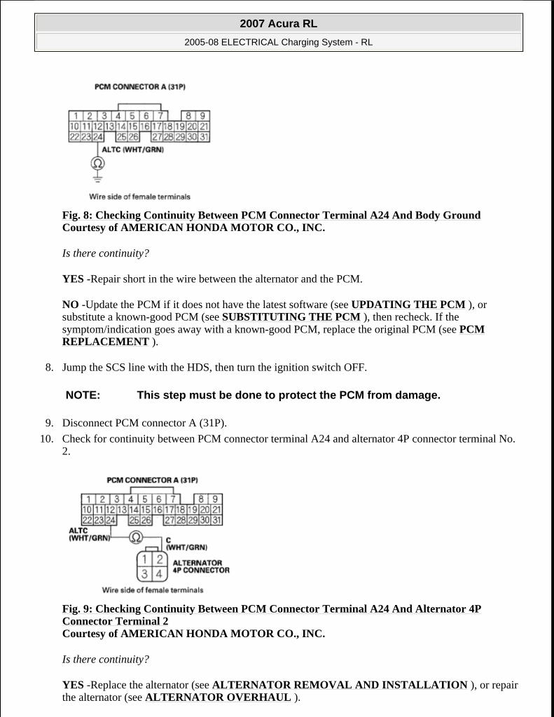
Fig. 8: Checking Continuity Between PCM Connector Terminal A24 And Body Ground Courtesy of AMERICAN HONDA MOTOR CO., INC.
Is there continuity?
YES -Repair short in the wire between the alternator and the PCM.
NO -Update the PCM if it does not have the latest software (see UPDATING THE PCM ), or substitute a known-good PCM (see SUBSTITUTING THE PCM ), then recheck. If the symptom/indication goes away with a known-good PCM, replace the original PCM (see PCM REPLACEMENT ).
8. Jump the SCS line with the HDS, then turn the ignition switch OFF.
9. Disconnect PCM connector A (31P).
10. Check for continuity between PCM connector terminal A24 and alternator 4P connector terminal No. 2.
Fig. 9: Checking Continuity Between PCM Connector Terminal A24 And Alternator 4P Connector Terminal 2 Courtesy of AMERICAN HONDA MOTOR CO., INC.
Is there continuity?
YES -Replace the alternator (see ALTERNATOR REMOVAL AND INSTALLATION ), or repair the alternator (see ALTERNATOR OVERHAUL ).
NOTE: This step must be done to protect the PCM from damage.
2007 Acura RL
2005-08 ELECTRICAL Charging System - RL
me
Friday, June 05, 2009 2:41:57 PM Page 9 © 2005 Mitchell Repair Information Company, LLC.

NO -Repair open in the wire between the alternator and the PCM.
DRIVE BELT INSPECTION
1. Remove the right upper fender trim.
Fig. 10: Identifying Right Upper Fender Trim Courtesy of AMERICAN HONDA MOTOR CO., INC.
2. Inspect the belt for cracks or damage. If the belt is cracked or damaged, replace it.
3. Check that the auto-tensioner indicator (A) is within the standard range (B) as shown. If it is out of the standard range, replace the drive belt (see DRIVE BELT REPLACEMENT ).
Fig. 11: Identifying Auto-Tensioner Indicator Range Courtesy of AMERICAN HONDA MOTOR CO., INC.
DRIVE BELT REPLACEMENT
2007 Acura RL
2005-08 ELECTRICAL Charging System - RL
me
Friday, June 05, 2009 2:41:57 PM Page 10 © 2005 Mitchell Repair Information Company, LLC.
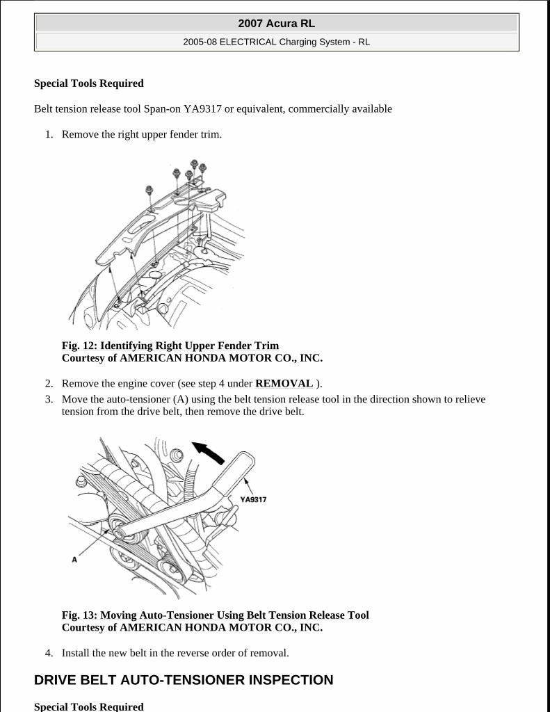
Special Tools Required
Belt tension release tool Span-on YA9317 or equivalent, commercially available
1. Remove the right upper fender trim.
Fig. 12: Identifying Right Upper Fender Trim Courtesy of AMERICAN HONDA MOTOR CO., INC.
2. Remove the engine cover (see step 4 under REMOVAL ).
3. Move the auto-tensioner (A) using the belt tension release tool in the direction shown to relieve tension from the drive belt, then remove the drive belt.
Fig. 13: Moving Auto-Tensioner Using Belt Tension Release Tool Courtesy of AMERICAN HONDA MOTOR CO., INC.
4. Install the new belt in the reverse order of removal.
DRIVE BELT AUTO-TENSIONER INSPECTION
Special Tools Required
2007 Acura RL
2005-08 ELECTRICAL Charging System - RL
me
Friday, June 05, 2009 2:41:57 PM Page 11 © 2005 Mitchell Repair Information Company, LLC.

Belt tension release tool Span-on YA9317 or equivalent, commercially available
1. Remove the right upper fender trim (see step 1 ).
2. Turn the ignition switch ON (II), and make sure to turn the A/C switch OFF. Turn the ignition switch OFF.
3. Check the position of the auto-tensioner indicator's pointer (A). Start the engine, then check the position again with the engine idling. If the position of the indicator moves or fluctuates a lot, replace the auto-tensioner (see DRIVE BELT AUTO-TENSIONER REPLACEMENT ).
Fig. 14: Identifying Auto-Tensioner Indicator's Pointer Courtesy of AMERICAN HONDA MOTOR CO., INC.
4. Check for abnormal noise from the tensioner pulley. If you hear any abnormal noise, replace the auto-tensioner pulley (see TENSIONER PULLEY REPLACEMENT ).
5. Remove the drive belt (see DRIVE BELT REPLACEMENT ).
6. Move the auto-tensioner within its limit using the belt tension release tool in the direction shown. Check that the tensioner moves smoothly and without any abnormal noise. If the tensioner does not move smoothly, or you hear abnormal noises, replace the auto-tensioner (see DRIVE BELT AUTO-TENSIONER REPLACEMENT ).
Fig. 15: Moving Auto-Tensioner Within Its Limit Using Belt Tension Release Tool Courtesy of AMERICAN HONDA MOTOR CO., INC.
7. Remove the auto-tensioner (see DRIVE BELT AUTO-TENSIONER REPLACEMENT ).
8. Clamp the auto-tensioner (A) by using a 10 mm bolt (B), 8 mm bolt (C), and a vise (D) as shown. Do not clamp the auto-tensioner itself.
2007 Acura RL
2005-08 ELECTRICAL Charging System - RL
me
Friday, June 05, 2009 2:41:58 PM Page 12 © 2005 Mitchell Repair Information Company, LLC.
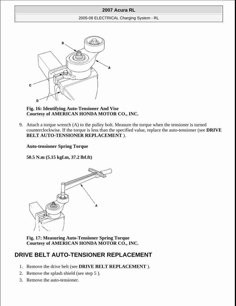
Fig. 16: Identifying Auto-Tensioner And Vise Courtesy of AMERICAN HONDA MOTOR CO., INC.
9. Attach a torque wrench (A) to the pulley bolt. Measure the torque when the tensioner is turned counterclockwise. If the torque is less than the specified value, replace the auto-tensioner (see DRIVE BELT AUTO-TENSIONER REPLACEMENT ).
Auto-tensioner Spring Torque
50.5 N.m (5.15 kgf.m, 37.2 lbf.ft)
Fig. 17: Measuring Auto-Tensioner Spring Torque Courtesy of AMERICAN HONDA MOTOR CO., INC.
DRIVE BELT AUTO-TENSIONER REPLACEMENT
1. Remove the drive belt (see DRIVE BELT REPLACEMENT ).
2. Remove the splash shield (see step 5 ).
3. Remove the auto-tensioner.
2007 Acura RL
2005-08 ELECTRICAL Charging System - RL
me
Friday, June 05, 2009 2:41:58 PM Page 13 © 2005 Mitchell Repair Information Company, LLC.
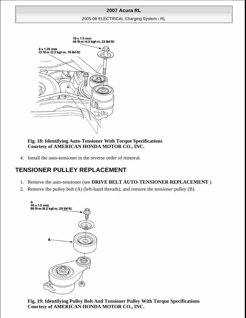
Fig. 18: Identifying Auto-Tensioner With Torque Specifications Courtesy of AMERICAN HONDA MOTOR CO., INC.
4. Install the auto-tensioner in the reverse order of removal.
TENSIONER PULLEY REPLACEMENT
1. Remove the auto-tensioner (see DRIVE BELT AUTO-TENSIONER REPLACEMENT ).
2. Remove the pulley bolt (A) (left-hand threads), and remove the tensioner pulley (B).
Fig. 19: Identifying Pulley Bolt And Tensioner Pulley With Torque Specifications Courtesy of AMERICAN HONDA MOTOR CO., INC.
2007 Acura RL
2005-08 ELECTRICAL Charging System - RL
me
Friday, June 05, 2009 2:41:58 PM Page 14 © 2005 Mitchell Repair Information Company, LLC.

3. Install the tensioner pulley in the reverse order of removal.
ALTERNATOR REMOVAL AND INSTALLATION
REMOVAL
1. Make sure you have the anti-theft codes for the audio system and navigation system. Make sure the ignition switch is OFF.
2. Remove the right upper fender trim (A), battery trim (B), left upper fender trim (C), then remove the upper grille cover (D).
Fig. 20: Identifying Right/Left Upper Fender Trim, Battery Trim And Upper Grille Cover Courtesy of AMERICAN HONDA MOTOR CO., INC.
3. Disconnect the negative cable from the battery.
4. Raise the vehicle on the lift to full height.
5. Remove the splash shield.
Fig. 21: Identifying Splash Shield Courtesy of AMERICAN HONDA MOTOR CO., INC.
2007 Acura RL
2005-08 ELECTRICAL Charging System - RL
me
Friday, June 05, 2009 2:41:58 PM Page 15 © 2005 Mitchell Repair Information Company, LLC.
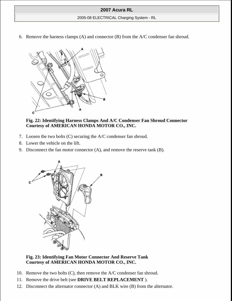
6. Remove the harness clamps (A) and connector (B) from the A/C condenser fan shroud.
Fig. 22: Identifying Harness Clamps And A/C Condenser Fan Shroud Connector Courtesy of AMERICAN HONDA MOTOR CO., INC.
7. Loosen the two bolts (C) securing the A/C condenser fan shroud.
8. Lower the vehicle on the lift.
9. Disconnect the fan motor connector (A), and remove the reserve tank (B).
Fig. 23: Identifying Fan Motor Connector And Reserve Tank Courtesy of AMERICAN HONDA MOTOR CO., INC.
10. Remove the two bolts (C), then remove the A/C condenser fan shroud.
11. Remove the drive belt (see DRIVE BELT REPLACEMENT ).
12. Disconnect the alternator connector (A) and BLK wire (B) from the alternator.
2007 Acura RL
2005-08 ELECTRICAL Charging System - RL
me
Friday, June 05, 2009 2:41:58 PM Page 16 © 2005 Mitchell Repair Information Company, LLC.

Fig. 24: Identifying Alternator Connector And BLK Wire Courtesy of AMERICAN HONDA MOTOR CO., INC.
13. Remove the bolt (C) securing the harness holder.
14. Remove the mounting bolt (A) and alternator bracket mounting bolt (B), then remove the alternator.
Fig. 25: Identifying Alternator Bracket Mounting Bolt Courtesy of AMERICAN HONDA MOTOR CO., INC.
INSTALLATION
1. Install the alternator.
2007 Acura RL
2005-08 ELECTRICAL Charging System - RL
me
Friday, June 05, 2009 2:41:58 PM Page 17 © 2005 Mitchell Repair Information Company, LLC.

Fig. 26: Identifying Alternator With Torque Specifications Courtesy of AMERICAN HONDA MOTOR CO., INC.
2. Connect the alternator connector (A) and the BLK wire (B) to the alternator.
Fig. 27: Identifying Alternator Connector And BLK Wire With Torque Specifications Courtesy of AMERICAN HONDA MOTOR CO., INC.
3. Install the bolt (C) securing the harness holder.
4. Install the drive belt (see DRIVE BELT INSPECTION ).
5. Install the A/C condenser fan shroud (A), and tighten the bolts.
2007 Acura RL
2005-08 ELECTRICAL Charging System - RL
me
Friday, June 05, 2009 2:41:58 PM Page 18 © 2005 Mitchell Repair Information Company, LLC.
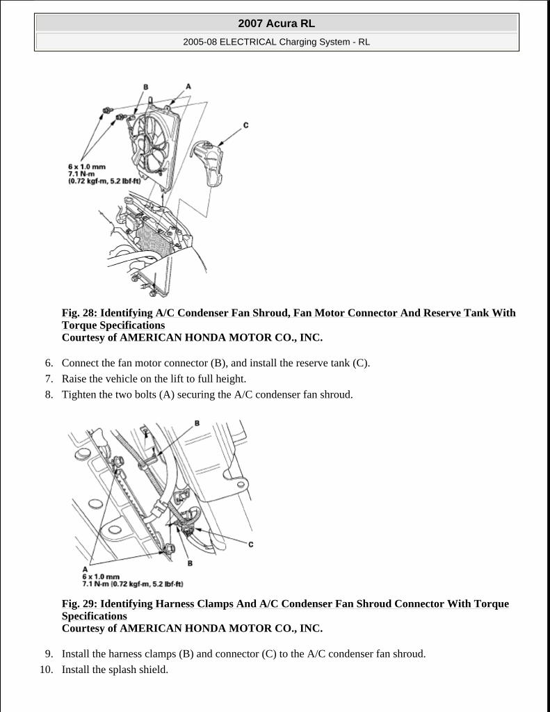
Fig. 28: Identifying A/C Condenser Fan Shroud, Fan Motor Connector And Reserve Tank With Torque Specifications Courtesy of AMERICAN HONDA MOTOR CO., INC.
6. Connect the fan motor connector (B), and install the reserve tank (C).
7. Raise the vehicle on the lift to full height.
8. Tighten the two bolts (A) securing the A/C condenser fan shroud.
Fig. 29: Identifying Harness Clamps And A/C Condenser Fan Shroud Connector With Torque Specifications Courtesy of AMERICAN HONDA MOTOR CO., INC.
9. Install the harness clamps (B) and connector (C) to the A/C condenser fan shroud.
10. Install the splash shield.
2007 Acura RL
2005-08 ELECTRICAL Charging System - RL
me
Friday, June 05, 2009 2:41:58 PM Page 19 © 2005 Mitchell Repair Information Company, LLC.
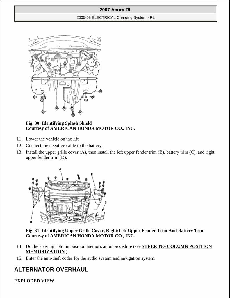
Fig. 30: Identifying Splash Shield Courtesy of AMERICAN HONDA MOTOR CO., INC.
11. Lower the vehicle on the lift.
12. Connect the negative cable to the battery.
13. Install the upper grille cover (A), then install the left upper fender trim (B), battery trim (C), and right upper fender trim (D).
Fig. 31: Identifying Upper Grille Cover, Right/Left Upper Fender Trim And Battery Trim Courtesy of AMERICAN HONDA MOTOR CO., INC.
14. Do the steering column position memorization procedure (see STEERING COLUMN POSITION MEMORIZATION ).
15. Enter the anti-theft codes for the audio system and navigation system.
ALTERNATOR OVERHAUL
EXPLODED VIEW
2007 Acura RL
2005-08 ELECTRICAL Charging System - RL
me
Friday, June 05, 2009 2:41:58 PM Page 20 © 2005 Mitchell Repair Information Company, LLC.

Fig. 32: Exploded View Of Alternator Courtesy of AMERICAN HONDA MOTOR CO., INC.
Special Tools Required
Handle driver 07749-0010000
Attachment, 42 x 47 mm 07746-0010300
ALTERNATOR DISASSEMBLY
1. Test the alternator and regulator before you remove them (see ALTERNATOR AND REGULATOR CIRCUIT TROUBLESHOOTING ).
2. Remove the alternator (see ALTERNATOR REMOVAL AND INSTALLATION ).
3. If the front bearing needs replacing, remove the pulley locknut with a 10 mm wrench (A) and a 22 mm wrench (B). If necessary, use an impact wrench.
NOTE: Refer to the EXPLODED VIEW as needed during this procedure.
2007 Acura RL
2005-08 ELECTRICAL Charging System - RL
me
Friday, June 05, 2009 2:41:58 PM Page 21 © 2005 Mitchell Repair Information Company, LLC.

Fig. 33: Removing Pulley Locknut Courtesy of AMERICAN HONDA MOTOR CO., INC.
4. Remove the three flange nuts.
Fig. 34: Identifying Flange Nuts Courtesy of AMERICAN HONDA MOTOR CO., INC.
5. Remove the end cover (A) and the insulator (B). A.
Fig. 35: Identifying End Cover And Insulator Courtesy of AMERICAN HONDA MOTOR CO., INC.
2007 Acura RL
2005-08 ELECTRICAL Charging System - RL
me
Friday, June 05, 2009 2:41:58 PM Page 22 © 2005 Mitchell Repair Information Company, LLC.
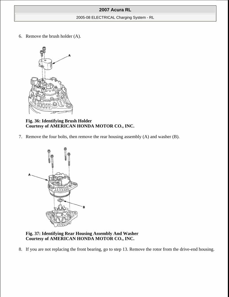
6. Remove the brush holder (A).
Fig. 36: Identifying Brush Holder Courtesy of AMERICAN HONDA MOTOR CO., INC.
7. Remove the four bolts, then remove the rear housing assembly (A) and washer (B).
Fig. 37: Identifying Rear Housing Assembly And Washer Courtesy of AMERICAN HONDA MOTOR CO., INC.
8. If you are not replacing the front bearing, go to step 13. Remove the rotor from the drive-end housing.
2007 Acura RL
2005-08 ELECTRICAL Charging System - RL
me
Friday, June 05, 2009 2:41:58 PM Page 23 © 2005 Mitchell Repair Information Company, LLC.

Fig. 38: Identifying Rotor And Drive-End Housing Courtesy of AMERICAN HONDA MOTOR CO., INC.
9. Inspect the rotor shaft for scoring, and inspect the bearing journal surface in the drive-end housing for seizure marks.
If the rotor is damaged, replace the rotor assembly.
If the rotor is OK, go to step 10.
10. Remove the front bearing retainer plate.
Fig. 39: Identifying Front Bearing Retainer Plate Courtesy of AMERICAN HONDA MOTOR CO., INC.
11. Drive out the front bearing with a brass drift and hammer.
2007 Acura RL
2005-08 ELECTRICAL Charging System - RL
me
Friday, June 05, 2009 2:41:58 PM Page 24 © 2005 Mitchell Repair Information Company, LLC.

Fig. 40: Removing Front Bearing Courtesy of AMERICAN HONDA MOTOR CO., INC.
12. Install a new front bearing in the drive-end housing with a hammer, the handle driver, and attachment (42 x 47 mm).
Fig. 41: Installing Front Bearing Courtesy of AMERICAN HONDA MOTOR CO., INC.
Alternator Brush Inspection
13. Measure the length of both brushes (A) with a vernier caliper (B).
If either brush is shorter than the service limit, replace the brush holder assembly.
If the brush length is OK, go to step 14.
Alternator Brush Length
Standard (New): 10.5 mm (0.41 in.)
Service Limit: 1.5 mm (0.06 in.)
2007 Acura RL
2005-08 ELECTRICAL Charging System - RL
me
Friday, June 05, 2009 2:41:58 PM Page 25 © 2005 Mitchell Repair Information Company, LLC.
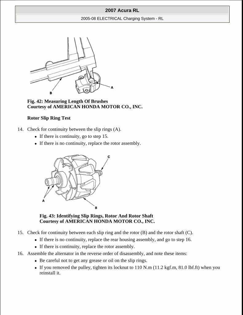
Fig. 42: Measuring Length Of Brushes Courtesy of AMERICAN HONDA MOTOR CO., INC.
Rotor Slip Ring Test
14. Check for continuity between the slip rings (A).
If there is continuity, go to step 15.
If there is no continuity, replace the rotor assembly.
Fig. 43: Identifying Slip Rings, Rotor And Rotor Shaft Courtesy of AMERICAN HONDA MOTOR CO., INC.
15. Check for continuity between each slip ring and the rotor (B) and the rotor shaft (C).
If there is no continuity, replace the rear housing assembly, and go to step 16.
If there is continuity, replace the rotor assembly.
16. Assemble the alternator in the reverse order of disassembly, and note these items:
Be careful not to get any grease or oil on the slip rings.
If you removed the pulley, tighten its locknut to 110 N.m (11.2 kgf.m, 81.0 lbf.ft) when you reinstall it.
2007 Acura RL
2005-08 ELECTRICAL Charging System - RL
me
Friday, June 05, 2009 2:41:58 PM Page 26 © 2005 Mitchell Repair Information Company, LLC.