characterization of goce gps a

1
1 Introduction 4 GOCE GPS Antenna Calibration Campaign 5 Results The outcome of the stand-alone calibrations is, that the antennas show phase center variations in azimuth and elevation of up to more than 1 cm in L1 and L2. flat surface instead of a rough honeycomb structure did not induce considerable changes. ß Mounted on the GOCE solar wing model, significant changes in phase and amplitude can be noticed in particular for the ionospheric-free signal L0. The differences between stand-alone and solar wing PCV are illustrated in Fig. 6. At this, the use of a More results are given in Dil ner and Seeber 2005. Institut für Erdmessung CHARACTERIZATION OF GOCE GPS ANTENNAS mbH (Geo++), Steinriede 8, 30827 Garbsen, Germa y 3 1 1 2 2 3 Florian Dilßner , Günter Seeber , Martin Schmitz , Gerhard Wübbena , Giovanni Toso , Damien Maeusli 1 Institut für Erdmessung (IfE), Universität Hannover, Schneiderberg 50, 30167 Hannover, Germany 2 Gesellschaft für satellitengestütze geodätische und navigatorische Technologien n 3 European Space Research and Technology Centre (ESTEC), Keplerlaan 1, 2200 AG Noordwijk ZH, Netherlands Within the framework of the Gravity Field and Steady-State Ocean Circulation Explorer (GOCE) mission, which is scheduled for launch in 2007 by the European Space Agency (ESA), a high accuracy Satellite-to-Satellite Tracking Instrument (SSTI) will be used for real time navigation and precise orbit determination. The instrument consists of two advanced dual-frequency, 12-channel LAGRANGE GPS receivers as well as two hemispherical-coverage receiving antennas. These antennas are directly mounted on the edge of one of the metallic solar array wings of the spacecraft (Fig. 1). In addition to phase center variations (PCV), near field effects like multipath, diffraction and imaging induced by the close vicinity of the antenna can seriously affect the measurement performance of the SSTI unit. Due to restricted space and for reducing the available power aboard the satellite, the GPS antennas are directly installed on top of the solar wing (Fig. 3) with boresight direction to zenith. Two dummy antennas are mounted on the opposite panel. The positions have been optimized by numerical electromagnetic simulations. The most critical interactions with the spacecraft will be caused by the wing, especially for the antenna located in position A2 (Polimeni 2004). The GOCE antenna calibration campaign was executed in April 2005 on the rooftop of the Institut für Erdmessung. Several experiments were performed in order to characterize the phase center variations and carrier to noise behaviour of the two antenna candidates. All measurements Each antenna was calibrated once mounted in stand-alone mode and once mounted on a simplified GOCE solar wing model (Fig. 5). The top surface of this wing is characterized by a metallic honeycomb structure with cells of about 1-cm size. In order to evaluate the influence of the rough honeycomb structure, the wing was also covered by a flat metallic tape. have been modelled via spherical harmonic expansions of degree and order (8,5). References Dilßner, F., Seeber, G. (2005): Absolute Field Calibration of the GOCE GPS Antennas RYMSA Quadrifilar Helix and LABEN Cosmo Patch. ESTEC Test Report, Hannover, 2005. Polimeni, D. (2004): GOCE SSTI Antenna Performance. ESTEC Working Paper, Noordwijk, 2004. Schmitz, M., Wübbena, G., Boettcher, G. (2004): Near Field Effects of a Car Roof on TPSHIPERPLUS Phase Variations. Geo++ White Paper, http://www.geopp.com/publications, Garbsen, 2004. Acknowledgements The work described on this poster was funded by the European Space Agency (ESA). The preparation and execution of the robot calibration campaign was supported by Alcatel Alenia Space Italy from Turin. 3 Automated Absolute Field Calibration The fundamental concept of this calibration method is based on the rigorous separation between phase center variations and site dependent multipath effects. By means of a precisely calibrated and fast moving robot, the antenna will be tilted and rotated. Since time differences between consecutive epochs amount just a few seconds, the environment multipath error is highly correlated and can be well described as a stochastic process. Distance dependent errors cancel out using a very close-by reference station. Due to this observation procedure, it is possible to obtain a clear PCV signal free of any remaining systematic effects. 6 Summary and Conclusions Therefore, several experiments were performed using the Automated Absolute Field Calibration Technique developed by the Institut für Erdmessung (IfE) of the University of Hannover and Geo++ at Garbsen, Germany. In order to characterize the interactions with the spacecraft, the antennas were calibrated not only in stand- alone mode but also together with a representative cut-out of GOCE's solar wing which was mounted beneath the antennas. The differences of both set-ups in terms of PCV and C/N reveal the influence of the near field effects O caused by the wing. Anechoic chamber calibrations as well as numerical simulations done at the European Space Research and Technology Centre (ESTEC) have confirmed the results. The Quadrifilar Helix (QFH) antenna was specifically developed for the GOCE SSTI application by RYMSA, Spain (Fig. 2). The antenna provides a broad gain pattern with a very sharp drop-off near the horizon and was designed with high rejection to Left Hand Circularly Polarized (LHCP) signals in order to minimize multipath interferences. Because of the unsymmetrical structure of the antenna feeding part and the fact that the number of turns of the helical arms is equal to 2/3, significant azimuthal phase center variations can be expected. In order to reveal near field effects like multipath, the antenna has to be mounted on the robot together with a representative model of the real antenna environment (Schmitz et. al. 2004). During the calibration, this surface model will now cause multipath interferences (Fig. 4). Because the geometric relationship between antenna and environment cut-out will be held constant, reflections coming from the same direction with respect to the antenna coordinate system, induce the same multipath signal. Hence, the effect is not eliminated by the observation procedure. Instead, an additional signal pattern caused by the near field multipath superimposes the PCV signal. Comparing the measured pattern with the PCV results of an isolated antenna calibration, the influence of the near field can be estimated and analyzed. Fig. 3. Positions of GPS antennas Fig. 2. QFH antenna Fig. 1. GOCE S/C with payload Fig.4. Near field multipath A second antenna model was selected in order to have a possible backup solution. It contains a standard Dorne Margolin DM-145-10 patch element which is covered by a plastic housing and has a metallic ground plane in square shape. Fig. 6. Influence of GOCE solar wing on PCV of RYMSA QFH (left) and COSMO PATCH (right) antenna The SSTI antenna calibration results are essential for achieving a 1-cm accuracy level in precise orbit determination for the ESA GOCE mission to be launched in 2007. In order to fully meet the accuracy requirements, near field effects like multipath disturbances have to be considered as they can conspicuously modify the measurement performance. Depending on carrier frequency, antenna type and position, one can observe that the presence of the spacecraft’s solar wing can cause changes of up to 3 cm in phase and 5 dB-Hz in amplitude. In case of the GOCE mission, special attention needs to be paid to the ionospheric-free signal L0 which amplifies antenna near field effects once more by a factor of 3 (see Fig. 6). The is of particular relevance because for the satellite, a mean orbital altitude of 250 km has been chosen where ionospheric propagation delays still play a non-negligible role. The Automated Absolute Field Calibration provides a powerful mean to correct for this effect. linear combination ® INTERGEO / Geodätische Woche 2005, 4.-6. October, Düsseldorf, Germany Fig. 5. Mechanical set-ups for robot calibration campaign 2 GOCE SSTI GPS Antennas ® Geo++

Upload: others

Post on 18-Nov-2021

3 views

Category:

Documents


0 download

TRANSCRIPT

1 Introduction 4 GOCE GPS Antenna Calibration Campaign

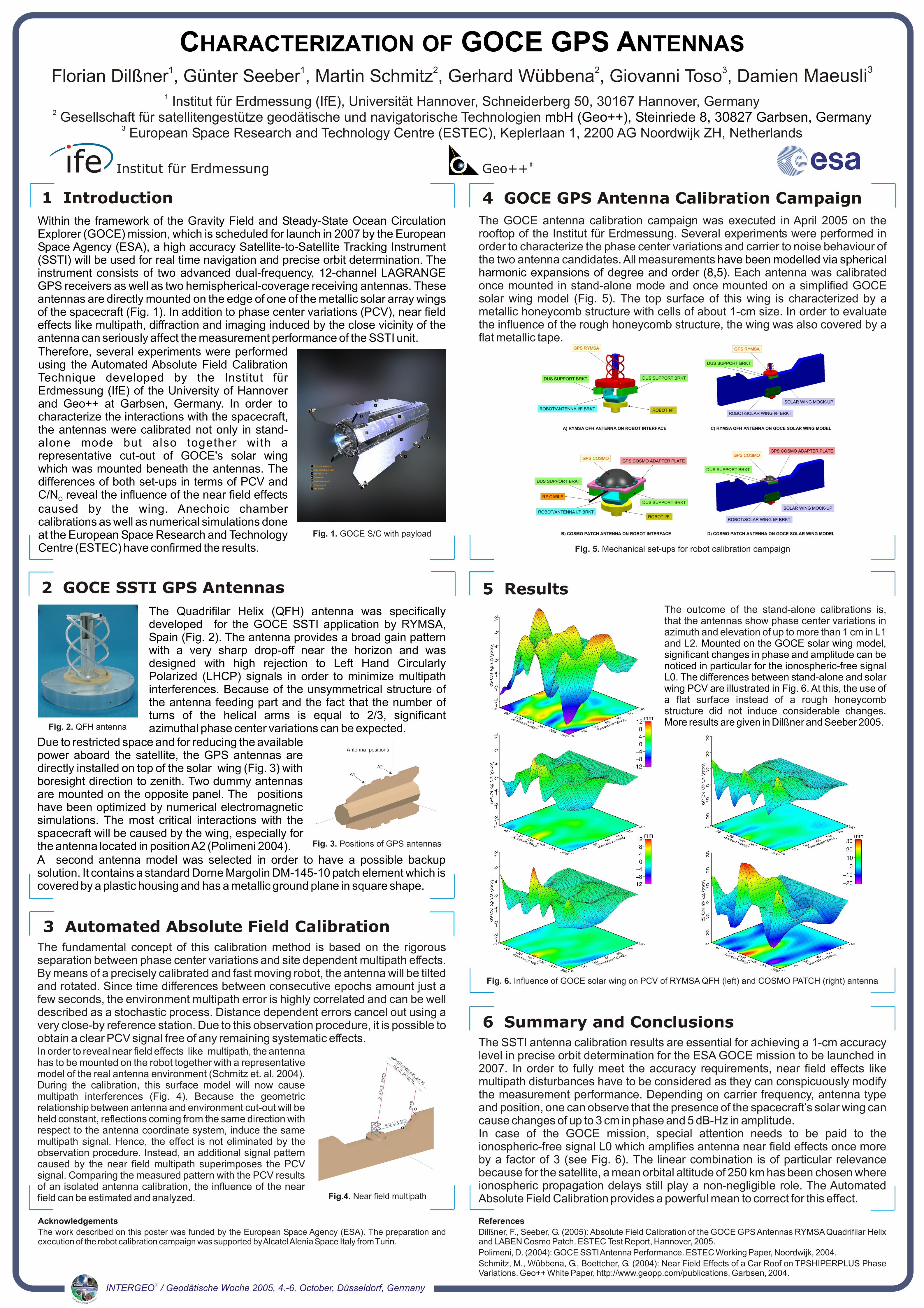
5 ResultsThe outcome of the stand-alone calibrations is, that the antennas show phase center variations in azimuth and elevation of up to more than 1 cm in L1 and L2.

flat surface instead of a rough honeycomb structure did not induce considerable changes.

ß

Mounted on the GOCE solar wing model, significant changes in phase and amplitude can be noticed in particular for the ionospheric-free signal L0. The differences between stand-alone and solar wing PCV are illustrated in Fig. 6. At this, the use of a

More results are given in Dil ner and Seeber 2005.

Institut für Erdmessung

CHARACTERIZATION OF GOCE GPS ANTENNAS

mbH (Geo++), Steinriede 8, 30827 Garbsen, Germa y

31 1 2 2 3Florian Dilßner , Günter Seeber , Martin Schmitz , Gerhard Wübbena , Giovanni Toso , Damien Maeusli1 Institut für Erdmessung (IfE), Universität Hannover, Schneiderberg 50, 30167 Hannover, Germany

2 Gesellschaft für satellitengestütze geodätische und navigatorische Technologien n3 European Space Research and Technology Centre (ESTEC), Keplerlaan 1, 2200 AG Noordwijk ZH, Netherlands

Within the framework of the Gravity Field and Steady-State Ocean Circulation Explorer (GOCE) mission, which is scheduled for launch in 2007 by the European Space Agency (ESA), a high accuracy Satellite-to-Satellite Tracking Instrument (SSTI) will be used for real time navigation and precise orbit determination. The instrument consists of two advanced dual-frequency, 12-channel LAGRANGE GPS receivers as well as two hemispherical-coverage receiving antennas. These antennas are directly mounted on the edge of one of the metallic solar array wings of the spacecraft (Fig. 1). In addition to phase center variations (PCV), near field effects like multipath, diffraction and imaging induced by the close vicinity of the antenna can seriously affect the measurement performance of the SSTI unit.

Due to restricted space and for reducing the available power aboard the satellite, the GPS antennas are directly installed on top of the solar wing (Fig. 3) with boresight direction to zenith. Two dummy antennas are mounted on the opposite panel. The positions have been optimized by numerical electromagnetic simulations. The most critical interactions with the spacecraft will be caused by the wing, especially for the antenna located in position A2 (Polimeni 2004).

The GOCE antenna calibration campaign was executed in April 2005 on the rooftop of the Institut für Erdmessung. Several experiments were performed in order to characterize the phase center variations and carrier to noise behaviour of the two antenna candidates. All measurements

Each antenna was calibrated once mounted in stand-alone mode and once mounted on a simplified GOCE solar wing model (Fig. 5). The top surface of this wing is characterized by a metallic honeycomb structure with cells of about 1-cm size. In order to evaluate the influence of the rough honeycomb structure, the wing was also covered by a flat metallic tape.

have been modelled via spherical harmonic expansions of degree and order (8,5).

References

Dilßner, F., Seeber, G. (2005): Absolute Field Calibration of the GOCE GPS Antennas RYMSA Quadrifilar Helix and LABEN Cosmo Patch. ESTEC Test Report, Hannover, 2005.

Polimeni, D. (2004): GOCE SSTI Antenna Performance. ESTEC Working Paper, Noordwijk, 2004.

Schmitz, M., Wübbena, G., Boettcher, G. (2004): Near Field Effects of a Car Roof on TPSHIPERPLUS Phase Variations. Geo++ White Paper, http://www.geopp.com/publications, Garbsen, 2004.

Acknowledgements

The work described on this poster was funded by the European Space Agency (ESA). The preparation and execution of the robot calibration campaign was supported by Alcatel Alenia Space Italy from Turin.

3 Automated Absolute Field CalibrationThe fundamental concept of this calibration method is based on the rigorous separation between phase center variations and site dependent multipath effects. By means of a precisely calibrated and fast moving robot, the antenna will be tilted and rotated. Since time differences between consecutive epochs amount just a few seconds, the environment multipath error is highly correlated and can be well described as a stochastic process. Distance dependent errors cancel out using a very close-by reference station. Due to this observation procedure, it is possible to obtain a clear PCV signal free of any remaining systematic effects.

6 Summary and Conclusions

Therefore, several experiments were performed using the Automated Absolute Field Calibration Technique developed by the Institut für Erdmessung (IfE) of the University of Hannover and Geo++ at Garbsen, Germany. In order to characterize the interactions with the spacecraft, the antennas were calibrated not only in stand-alone mode but also together with a representative cut-out of GOCE's solar wing which was mounted beneath the antennas. The differences of both set-ups in terms of PCV and C/N reveal the influence of the near field effects O

caused by the wing. Anechoic chamber calibrations as well as numerical simulations done at the European Space Research and Technology Centre (ESTEC) have confirmed the results.

The Quadrifilar Helix (QFH) antenna was specifically developed for the GOCE SSTI application by RYMSA, Spain (Fig. 2). The antenna provides a broad gain pattern with a very sharp drop-off near the horizon and was designed with high rejection to Left Hand Circularly Polarized (LHCP) signals in order to minimize multipath interferences. Because of the unsymmetrical structure of the antenna feeding part and the fact that the number of turns of the helical arms is equal to 2/3, significant azimuthal phase center variations can be expected.

In order to reveal near field effects like multipath, the antenna has to be mounted on the robot together with a representative model of the real antenna environment (Schmitz et. al. 2004). During the calibration, this surface model will now cause multipath interferences (Fig. 4). Because the geometric relationship between antenna and environment cut-out will be held constant, reflections coming from the same direction with respect to the antenna coordinate system, induce the same multipath signal. Hence, the effect is not eliminated by the observation procedure. Instead, an additional signal pattern caused by the near field multipath superimposes the PCV signal. Comparing the measured pattern with the PCV results of an isolated antenna calibration, the influence of the near field can be estimated and analyzed.

Fig. 3. Positions of GPS antennas

Fig. 2. QFH antenna

Fig. 1. GOCE S/C with payload

Fig.4. Near field multipath

A second antenna model was selected in order to have a possible backup solution. It contains a standard Dorne Margolin DM-145-10 patch element which is covered by a plastic housing and has a metallic ground plane in square shape.

Fig. 6. Influence of GOCE solar wing on PCV of RYMSA QFH (left) and COSMO PATCH (right) antenna

The SSTI antenna calibration results are essential for achieving a 1-cm accuracy level in precise orbit determination for the ESA GOCE mission to be launched in 2007. In order to fully meet the accuracy requirements, near field effects like multipath disturbances have to be considered as they can conspicuously modify the measurement performance. Depending on carrier frequency, antenna type and position, one can observe that the presence of the spacecraft’s solar wing can cause changes of up to 3 cm in phase and 5 dB-Hz in amplitude. In case of the GOCE mission, special attention needs to be paid to the ionospheric-free signal L0 which amplifies antenna near field effects once more by a factor of 3 (see Fig. 6). The is of particular relevance because for the satellite, a mean orbital altitude of 250 km has been chosen where ionospheric propagation delays still play a non-negligible role. The Automated Absolute Field Calibration provides a powerful mean to correct for this effect.

linear combination

®INTERGEO / Geodätische Woche 2005, 4.-6. October, Düsseldorf, Germany

Fig. 5. Mechanical set-ups for robot calibration campaign

2 GOCE SSTI GPS Antennas

®Geo++