characteristics of a non-circulating transient flow …
TRANSCRIPT

Wei, N., et al.: Characteristics of a Non-Circulating Transient Flow during … THERMAL SCIENCE: Year 2019, Vol. 23, No. 4, pp. 2257-2264 2257
CHARACTERISTICS OF A NON-CIRCULATING TRANSIENT FLOW DURING GAS INVASION
IN THE UNDERBALANCED DRILLING PROCESS
by
Na WEI a*, Ying-Feng MENG
a, An-Qi LIU b, Hai-Tao LI
a, Lin JIANG a,
Li-Jun ZHENG c, Qiang FU
c, and Xin LV d
aState Key Laboratory of Oil and Gas Reservoir Geology and Exploitation, Southwest Petroleum University, Chengdu, China
bGeological Explorations and Development Institute, Chuan Qing Drilling Engineering Company Limited, Chengdu, China
cChina National Offshore Oil Corporation, Beijing, China dChina National Offshore Oil Corporation Research Institute Limited Liability Company,
Beijing, China
Original scientific paper https://doi.org/10.2298/TSCI1904257W
The wellbore flow in a liquid-based underbalanced drilling process consists of a steady multiphase flow during normal drilling and a transient gas-liquid flow without mud-cycling. The theory of steady multi-phase flow has been used to cal-culate the pressure profile of normal drilling. Therefore, it is vital to figure out how to calculate the transient pressure variation caused by formation fluid flow-ing into wellbore when the mud-cycling is stopped. In this paper, a numerical simulation method and a mathematic model are established to study the wellbore flow and to control pressure during the underbalanced drilling process with liq-uid-based mud. The results also shed a light on the hidden mechanism of this special flow. Key words: underbalanced drilling, non-circulating, gas invasion, regularity,
transient flow
Introduction
The conventional liquid-based underbalanced drilling (UBD) could protect the for-mation, while heavy slurry killing and tripping after stopping drilling could damage formation seriously [1]. Nowadays, the liquid-based UBD has been developing fast, and it becomes a crucial means to develop the deep reservoir of oil and gas efficiently [2, 3]. Generally the bot-tom-hole flowing pressure (BHFP) is lower than the reservoir pressure during various treat-ments, and the static pressure difference could be increased when a connection is made, every swabbing action during pulling out the hole could force a piece of formation flowing into wellbore when the mud-cycling of liquid-based UBD is stopped [4-6]. Therefore, it is neces-sary to study the flow behaviors of the formation fluid and special gas. The control equation, initial and boundary conditions are established firstly. Then, the dynamic mathematic model is established. Meanwhile, the characteristic parameters of gas-liquid flow are obtained from transient multiphase flow theory. Lastly, the solutions could evolve the laws and control
* Corresponding author, e-mail: [email protected] ––––––––––––––
Wei, N., et al.: Characteristics of a Non-Circulating Transient Flow during … 2258 THERMAL SCIENCE: Year 2019, Vol. 23, No. 4, pp. 2257-2264
methods for gas-liquid flow’s transient flow, which occurs during making a connection and swabbing in non-circulating liquid-based UBD.
Fundamental physical model and pseudo-steady mathematical model
The pseudo-steady state multiphase flow can use the calculation method for steady state to figure out the relationship between the characteristic parameters of the multiphase flow and time while the effect of pressure wave propagation is neglected [7].
The non-circulating pseudo-steady state multiphase flow in liquid-based UBD is mainly related to the dynamic analysis of the ascension by buoyancy force in static non-New-tonian fluid [8]. Combined the dynamic analysis, the computing method and mathematic model are established for pseudo-steady state flow. The performance laws of characteristic parameters for transient gas-liquid flow could be gained by combining transient multiphase flow’s theory and algorithm with the computing results of pseudo-steady flow [9].
The flow analysis of carrying out drilling fluid by gas invading the static non-Newton liquid singly under the condition of one-way opened
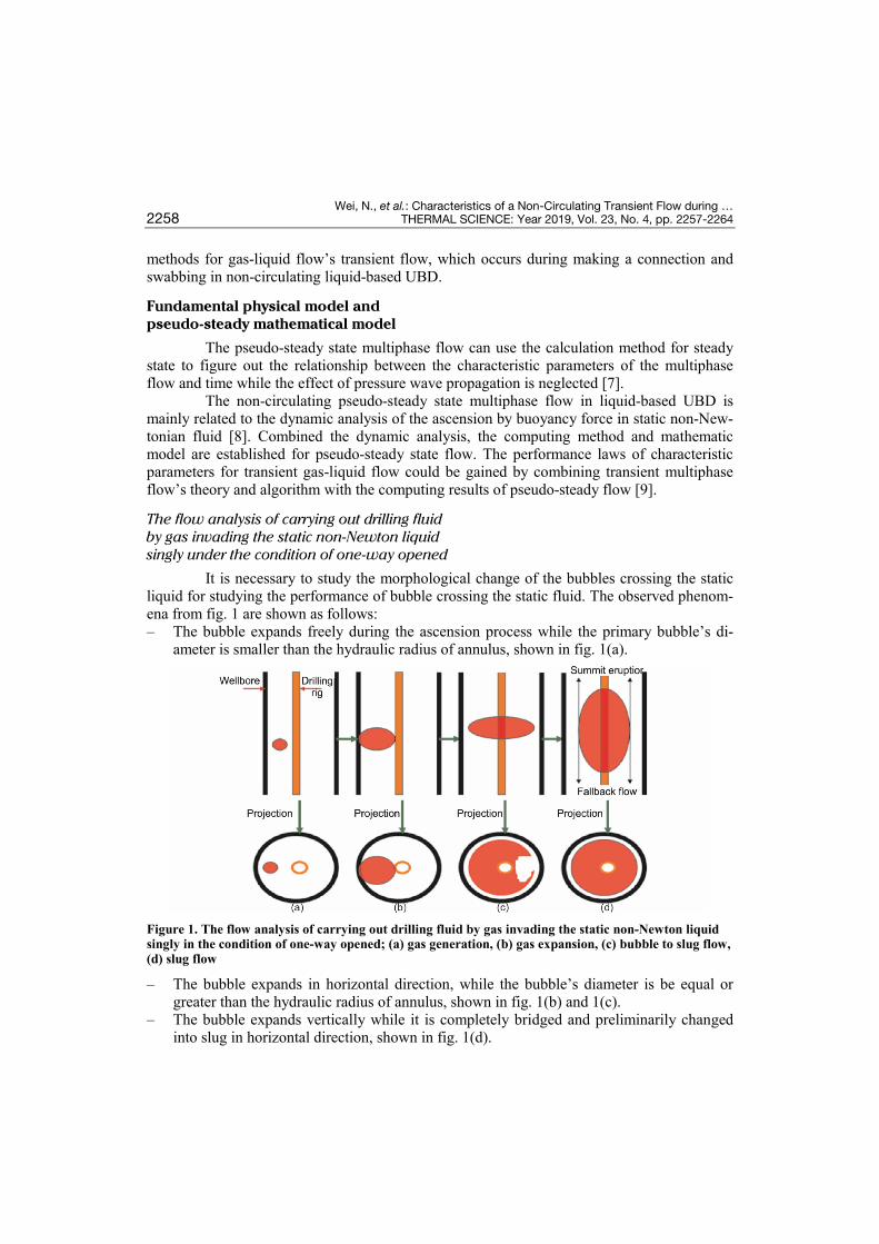
It is necessary to study the morphological change of the bubbles crossing the static liquid for studying the performance of bubble crossing the static fluid. The observed phenom-ena from fig. 1 are shown as follows: – The bubble expands freely during the ascension process while the primary bubble’s di-
ameter is smaller than the hydraulic radius of annulus, shown in fig. 1(a).
Figure 1. The flow analysis of carrying out drilling fluid by gas invading the static non-Newton liquid singly in the condition of one-way opened; (a) gas generation, (b) gas expansion, (c) bubble to slug flow, (d) slug flow
– The bubble expands in horizontal direction, while the bubble’s diameter is be equal or greater than the hydraulic radius of annulus, shown in fig. 1(b) and 1(c).
– The bubble expands vertically while it is completely bridged and preliminarily changed into slug in horizontal direction, shown in fig. 1(d).

Wei, N., et al.: Characteristics of a Non-Circulating Transient Flow during … THERMAL SCIENCE: Year 2019, Vol. 23, No. 4, pp. 2257-2264 2259
Characteristics parameter mathematical model for multiphase flow when gas crossing the non-Newtonian fluid
– The rising velocity of single gas invasion and the posi-tion of dynamic interface, fig. 2.
The rising velocity of gas is calculated by conven-tional model:
( )1/4
l g2l
( )g4.8663 0.5607U
ρ ρ σφ
ρ∞−
= +
(1)
The position of dynamic interface is:
L U T∞= ∆∑ (2)
– Gas holdup The restraint is from horizon when it crosses the static fluid in the pipe according to
the previous analysis and it only expands to slug in vertical direction. Therefore, the gas holdup could be obtained reversely by Harmathy’s relationship, which is:
1/4l g
2l
4.866 0.56074.866( )g
vφρ ρ σ
ρ
= −−
(3)
– The volume of the displaced drilling fluid q Aν φ= (4) – The BHFP f l slug 3gwp p p Hρ= + + (5)
where slug 2 f 2l 1 f1 back g l[ gg , (1 )] .p H Pp H p pρ ρ φ ρ φ= += + + + − The BHFP changing with time and the rate under pseudo-steady state at the well-
head could be obtained by solving the pseudo-steady state mathematical models for gas cross-ing the static fluid. On this basis, the transient numerical simulation results could be calculat-ed through the transient calculating method and process for gas-liquid two-phase flow.
The characteristic line method of the transient gas-liquid flow equation
The continuous equation is:
g g gg g g g g 0
vp pp p pv vt t z z zα α
α α α∂ ∂ ∂∂ ∂
+ + + + =∂ ∂ ∂ ∂ ∂
(6)
Kinematic equation is [10]:
g gl lg g l l g g g l l l gm w
v vv v pv v Ft t z z z
ρ α ρ α ρ α ρ α ρ∂ ∂∂ ∂ ∂
+ + + + + = − −∂ ∂ ∂ ∂ ∂
(7)
Figure 2. The flow pressure analysis of carrying out drilling fluid by gas invading the static non-Newton liquid singly in the condition of one-way opened

Wei, N., et al.: Characteristics of a Non-Circulating Transient Flow during … 2260 THERMAL SCIENCE: Year 2019, Vol. 23, No. 4, pp. 2257-2264
According to the slippage relationship between two phases, the gas velocity can be expressed as the liquid velocity, which is:
0 l 1g l
0 g 0 g1 1C Cv v
C Cαα α
= +− −
(8)
Substituting eq. (8) into the continuous equation and kinematic equation, the original hydromechanics equations would change the form [11-13]:
g0 0l lg g l g l l l g g g
0 g 0 g( )
1 1C Cv vv v vC t t t C
αρ α α ρ α ρ α
α α∂ ∂ ∂
+ − + + ⋅ − ∂ ∂ ∂ −
gl ll g l l l l( ) gm w
v v pv v v Fz z z z
αα ρ α ρ
∂ ∂ ∂ ∂⋅ + − + + = − − ∂ ∂ ∂ ∂
(9)
Rewriting previous equations as matrix form, it is shown:
t zA At x
∂ ∂+ =
∂ ∂u u f (10)
where u = (p αg v1)T.
g
l
g g 0 g l g g 0 ll l
0 g 0 g
0
0( )
01 1
t
p
A pC v v C
C C
α
αρ α ρ α α
ρ αα α
= − − +
− −
g 0 g l g 0 lg g
0 g 0 g
l l l l
g g g 0 g l g g g 0 ll l l
0 g 0 g
( )1 1 0
0( ) g
11 1
z
m w
p v C v p Cv
C C
A v pv pv C v v v C F
vC C
α α αα
α α
α αρ α ρ α α ρ
ρ αα α
− − −
= − − = − − − + − −
f (11)
If rewriting it into homogeneous linear equations, it will be changed into the follow-ing form, which is:
d dd dz t tzA A At t t
∂ − = − ∂
u uf (12)
According to the linear algebra theory, the necessary and sufficient condition of eq. (12) with the non-zero solution is that the determinant of coefficient is zero.
g 0 g l 0 g lg g
0 g 0 g
l l l l
g g 0 g l g g g 0 l gl l g
0 g 0 g
( ) ( )( )
1 1
( ) ( )( )( ) ( )
1 ( )1 1
x t
p v pC v pCv
C C
A A v p v pC v v v C v
vC C
λ α λ α αα λ
α α
λ α λ λ αρ α λ ρ α α λ
ρ α λα α
− − −−
− −
− = − − −− − −
− −− −
(13)
Wei, N., et al.: Characteristics of a Non-Circulating Transient Flow during … THERMAL SCIENCE: Year 2019, Vol. 23, No. 4, pp. 2257-2264 2261
The characteristic value of the equations could be obtained by making the determi-nant |Ax – Atλ| equal to zero.
Through simplification, characteristic line equation for two-phase flow equations is:
g
g 0 g
g
dd 0d (1 ) d:dd
p pt C tcx vt
αα α−
+ = −
=
(14)
g 1l g l l g l l g l
l
d dd ( ) ( ) ( )( g )d d d:dd
m wvp a v v v v a v v a F
t t tcx v at
αρ ρ α ρ
+
+ − − − − = − − − −
= +
(15)
where a is the wave’s propagation velocity in gas-liquid mixture. Combining eqs. (14) and (15), we could get the transient velocity for gas-liquid
flow, gas holdup, velocity and pressure for gas phase and liquid phase at each grid node.
Examples
Three numerical simulation examples are used to analyze the effect of gas produc-tion rate and wellhead backpressure to this flow and engineering security.
The basic parameters are as follows: well depth is 1600 m, diameter of the open hole is 0.1542 m, diameter of the production casing is 0.2445 m and landing depth is 1200 m, drill-ing fluid density is 1150 kg/m3, initial pressure difference is 1 MPa.
Drill-assembly: PDC with Ø152.4 mm + screw with Ø120.7 mm + drill color with Ø120.7 mm × 2 + pressure joint with Ø120.7 mm + float valve with Ø120.7 mm × 2 + extra heavy drill rod with Ø88.9 mm + drill pipe with Ø88.9 mm + drill pipe with Ø139.7 mm + float valve with Ø165 mm + drill pipe with Ø127 mm.
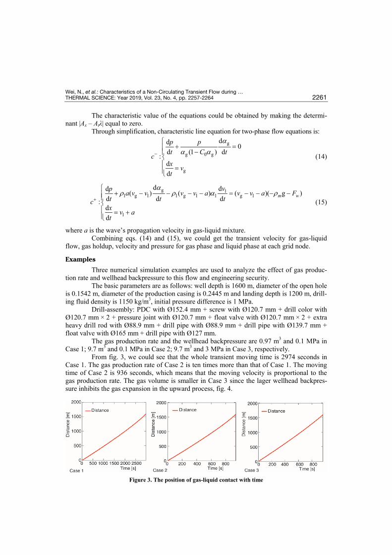
The gas production rate and the wellhead backpressure are 0.97 m3 and 0.1 MPa in Case 1; 9.7 m3 and 0.1 MPa in Case 2; 9.7 m3 and 3 MPa in Case 3, respectively.
From fig. 3, we could see that the whole transient moving time is 2974 seconds in Case 1. The gas production rate of Case 2 is ten times more than that of Case 1. The moving time of Case 2 is 936 seconds, which means that the moving velocity is proportional to the gas production rate. The gas volume is smaller in Case 3 since the lager wellhead backpres-sure inhibits the gas expansion in the upward process, fig. 4.
Figure 3. The position of gas-liquid contact with time

Wei, N., et al.: Characteristics of a Non-Circulating Transient Flow during … 2262 THERMAL SCIENCE: Year 2019, Vol. 23, No. 4, pp. 2257-2264
Figure 4. The volume of single gas with time
The accumulative and transient volume of carried-out mud with time are, respective-ly, shown in figs. 5 and 6. The results in fig. 5 show that the transient carried-out mud is in-creased by gas expansion with time. However, the results in fig. 6 show that the transient vol-ume of carried-out mud fluctuates rapidly in first 3 seconds, then the fluctuation range tends to smooth and the amplitude decreases rapidly.
Figure 5. The accumulative volume of carried-out mud with time
Figure 6. The transient volume of carried-out mud with time (detail view)
The relationship of the flow pressure with time is shown in fig. 7 and the detail view is in fig. 8. The results shown in fig. 7 demonstrate that for the gas expansion with time, more and more drilling mud is carried out and the flow pressure decreases slowly. However, the re-sults shown in fig. 8 demonstrate that the flow pressure fluctuates sharply during the initial period, then the fluctuation range tends to be smooth and the amplitude decreases rapidly. The variations of the flow pressure is similar to that of transient drilling mud.

Wei, N., et al.: Characteristics of a Non-Circulating Transient Flow during … THERMAL SCIENCE: Year 2019, Vol. 23, No. 4, pp. 2257-2264 2263
Figure 7. The relationship of the flow pressure with time
Figure 8. The relationship of the flow pressure with time (detail view)
The accumulative volume of carried-out mud in Case 3 is less than that in Case 2, the volume difference is about 4 m3. However, the maximum volume of carried-out mud at the beginning in Case 3 is 0.009 m3/s, 0.003 m3/s less than that in Case 2. The BHFP in Case 3 decreased to 13 MPa, 4 MPa higher than that in Case 2. The transient pressure fluctuation at the beginning in Case 3 is smaller than that in Case 2 obviously, which means the backpres-sure added at the wellhead could inhibit the BHFP fluctuation effectively.
In conclusion, when gas invasion occurred if mud cycling is stopped, adding the wellhead backpressure could inhibit the gas malignant expansion at the bottom-hole, and avoid the malignant blowout caused by amount of carried out mud during the ascension pro-cess of gas, which has a practical significance for the well control.
Conclusions
• The wellbore flow model of liquid-based UBD includes: the static gas-liquid-solid flow during normal drilling and transient gas-liquid flow during stopping mud cycling. It is vi-tal to figure out how to apply the transient change of BHFP caused by gas invasion to cal-culate the pressure profile of normal drilling.
• The basic flow equation for transient gas-liquid flow is established and solved by charac-teristic line iterative method. The solution provides a theory for dynamical well control and pressure prediction without mud cycling during liquid-based UBD.
• From the variation of gas-liquid flow characteristic parameters at different gas invasion rate, some conclusions are found: the moving velocity, the volume of displaced drilling fluid, and the fluctuation of BHFP are all proportional to the gas production rate. The ef-fect of backpressure on bottom-hole flow parameter is also simulated and its results

Wei, N., et al.: Characteristics of a Non-Circulating Transient Flow during … 2264 THERMAL SCIENCE: Year 2019, Vol. 23, No. 4, pp. 2257-2264
demonstrate that the wellhead backpressure could inhibit the gas expansion in the well and the pressure surge in bottom hole.
Nomenclature A – the cross-section area of wellbore, [m2] q – the volume of the instantaneous displacing
drilling fluid, [m3s–1] pwf – BHFP (the bottom-hole flowing
pressure), [Pa] pl – the flowing pressure drop of liquid over
the bubble, [Pa] pf – the frictional drag, [Pa] pslug – the pressure drop of slug flow, [Pa]
Greek symbols
v – the rising velocity of bubble, [ms–1] ρg – the density of gas phase, [kgm–3] ρl – the density of liquid phase, [kgm–3] σ – the interface tension coefficient
of gas-liquid, [Ncm–1] ϕ – gas holdup, [–]
Acknowledgment
The research was supported by the National Key Research and Development Pro-gram (Grant No. 2016YFC0304008), National Natural Science Funds of China (Grant No. 51334003).
References [1] Wei, N., et al., Sensitivity Analysis of Multiphase Flow in Annulus during Drilling of Marine Natural
Gas Hydrate Reservoirs, Journal of Natural Gas Science & Engineering, 36, Part A (2016), Nov., pp. 692-707
[2] Borkevoll, K. S., et al., Successful Field Use of Advanced Dynamic Models, Proceedings, IADC/SPE Drilling Conference, Society of Petroleum Engineers, Miami, Fla., USA, 2006
[3] Wei, N., et al., Annular Phase Behavior Analysis during Marine Natural Gas Hydrate Reservoir Drilling (In Chinese), Acta Petrolei Sinica, 38 (2017), 6, pp. 710-720
[4] Lee, S. J., et al., Pressure Wave Speeds from the Characteristics of Two Fluids, Two-Phase Hyperbolic Equation System, Multiphase Flow, 24 (1998), 5, pp. 855-866
[5] Wei, N., et al., Imaging of Gas-Liquid Annular Flows for Underbalanced Drilling Using Electrical Re-sistance Tomography, Flow Measurement and Instrumentation, 46 (2015), B, pp. 319-326
[6] Zuber, N., et al., Average Volumetric Concentration in Two-Phase Flow Systems, Journal of Heat Transfer, 87 (1965), 4, pp. 453-468
[7] Wei, N., et al., Characteristics Analysis of Multiphase Flow in Annulus in Natural Gas Hydrate Reser-voir Drilling, AER-Advances in Engineering Research, 40 (2015), Jan., pp. 396-400
[8] Martin, C. S., Padmanabhan, M., Pressure Pulses Propagation in Two-Component Slug Flow, Fluids Engineering, 101 (1979), 1, pp. 44-52
[9] Wei, N., et al., Reservoir Evaluation Technology During Underbalanced Drilling of Horizontal Wells in Gas Reservoirs, Geotechnical Testing Journal, 41 (2018), 1, pp. 164-170
[10] Wei, N., et al., Foam Drilling in Natural Gas Hydrate, Thermal Science, 19 (2015), 4, pp. 1403-1405 [11] Shi, H., et al., Drift-flux Parameters for Three-Phase Steady State Flow in Wellbores, SPE Journal, 10
(2005), 2, pp. 130-137 [12] Wei, N., et al., Cuttings Transport Models and Experimental Visualization of Underbalanced Horizontal
Drilling, Mathematical Problems in Engineering, 10 (2013), 2, pp. 1024-1230 [13] Wang, Z. Y., et al., Multiphase Flow Behavior in Annulus with Solid Gas Hydrate Considering Nature
Gas Hydrate Phase Transition, Petroleum Science, 6 (2009), 1, pp. 57-63
Paper submitted: March 1, 2018 © 2019 Society of Thermal Engineers of Serbia. Paper revised: September 1, 2018 Published by the Vinča Institute of Nuclear Sciences, Belgrade, Serbia. Paper accepted: October 1, 2018 This is an open access article distributed under the CC BY-NC-ND 4.0 terms and conditions.