chapters 1 & 2 - m. olsen's...
TRANSCRIPT


Conversion FactorsU.S. Customary Units to SI Units
To convert from To Multiply by
(Acceleration)foot/second2 (ft/sec2) meter/second2 (m/s2) 3.048 � 10�1*inch/second2 (in./sec2) meter/second2 (m/s2) 2.54 � 10�2*
(Area)foot2 (ft2) meter2 (m2) 9.2903 � 10�2
inch2 (in.2) meter2 (m2) 6.4516 � 10�4*(Density)
pound mass/inch3 (lbm/in.3) kilogram/meter3 (kg/m3) 2.7680 � 104
pound mass/foot3 (lbm/ft3) kilogram/meter3 (kg/m3) 1.6018 � 10(Force)
kip (1000 lb) newton (N) 4.4482 � 103
pound force (lb) newton (N) 4.4482(Length)
foot (ft) meter (m) 3.048 � 10�1*inch (in.) meter (m) 2.54 � 10�2*mile (mi), (U.S. statute) meter (m) 1.6093 � 103
mile (mi), (international nautical) meter (m) 1.852 � 103*(Mass)
pound mass (lbm) kilogram (kg) 4.5359 � 10�1
slug (lb-sec2/ft) kilogram (kg) 1.4594 � 10ton (2000 lbm) kilogram (kg) 9.0718 � 102
(Moment of force)pound-foot (lb-ft) newton-meter (N � m) 1.3558pound-inch (lb-in.) newton-meter (N � m) 0.1129 8
(Moment of inertia, area)inch4 meter4 (m4) 41.623 � 10�8
(Moment of inertia, mass)pound-foot-second2 (lb-ft-sec2) kilogram-meter2 (kg � m2) 1.3558
(Momentum, linear)pound-second (lb-sec) kilogram-meter/second (kg � m/s) 4.4482
(Momentum, angular)pound-foot-second (lb-ft-sec) newton-meter-second (kg � m2/s) 1.3558
(Power)foot-pound/minute (ft-lb/min) watt (W) 2.2597 � 10�2
horsepower (550 ft-lb/sec) watt (W) 7.4570 � 102
(Pressure, stress)atmosphere (std)(14.7 lb/in.2) newton/meter2 (N/m2 or Pa) 1.0133 � 105
pound/foot2 (lb/ft2) newton/meter2 (N/m2 or Pa) 4.7880 � 10pound/inch2 (lb/in.2 or psi) newton/meter2 (N/m2 or Pa) 6.8948 � 103
(Spring constant)pound/inch (lb/in.) newton/meter (N/m) 1.7513 � 102
(Velocity)foot/second (ft/sec) meter/second (m/s) 3.048 � 10�1*knot (nautical mi/hr) meter/second (m/s) 5.1444 � 10�1
mile/hour (mi/hr) meter/second (m/s) 4.4704 � 10�1*mile/hour (mi/hr) kilometer/hour (km/h) 1.6093
(Volume)foot3 (ft3) meter3 (m3) 2.8317 � 10�2
inch3 (in.3) meter3 (m3) 1.6387 � 10�5
(Work, Energy)British thermal unit (BTU) joule (J) 1.0551 � 103
foot-pound force (ft-lb) joule (J) 1.3558kilowatt-hour (kw-h) joule (J) 3.60 � 106*
*Exact value

SI Units Used in Mechanics
Quantity Unit SI Symbol
(Base Units)Length meter* mMass kilogram kgTime second s
(Derived Units)Acceleration, linear meter/second2 m/s2
Acceleration, angular radian/second2 rad/s2
Area meter2 m2
Density kilogram/meter3 kg/m3
Force newton N (� kg � m/s2)Frequency hertz Hz (� 1/s)Impulse, linear newton-second N � sImpulse, angular newton-meter-second N � m � sMoment of force newton-meter N � mMoment of inertia, area meter4 m4
Moment of inertia, mass kilogram-meter2 kg � m2
Momentum, linear kilogram-meter/second kg � m/s (� N � s)Momentum, angular kilogram-meter2/second kg � m2/s (� N � m � s)Power watt W (� J/s � N � m/s)Pressure, stress pascal Pa (� N/m2)Product of inertia, area meter4 m4
Product of inertia, mass kilogram-meter2 kg � m2
Spring constant newton/meter N/mVelocity, linear meter/second m/sVelocity, angular radian/second rad/sVolume meter3 m3
Work, energy joule J (� N � m)(Supplementary and Other Acceptable Units)
Distance (navigation) nautical mile (� 1,852 km)Mass ton (metric) t (� 1000 kg)Plane angle degrees (decimal) �Plane angle radian —Speed knot (1.852 km/h)Time day dTime hour hTime minute min
*Also spelled metre.
SI Unit Prefixes
Multiplication Factor Prefix Symbol1 000 000 000 000 � 1012 tera T
1 000 000 000 � 109 giga G1 000 000 � 106 mega M
1 000 � 103 kilo k100 � 102 hecto h10 � 10 deka da
0.1 � 10�1 deci d0.01 � 10�2 centi c
0.001 � 10�3 milli m0.000 001 � 10�6 micro �
0.000 000 001 � 10�9 nano n0.000 000 000 001 � 10�12 pico p
Selected Rules for Writing Metric Quantities1. (a) Use prefixes to keep numerical values generally between 0.1 and 1000.
(b) Use of the prefixes hecto, deka, deci, and centi should generally be avoidedexcept for certain areas or volumes where the numbers would be awkwardotherwise.
(c) Use prefixes only in the numerator of unit combinations. The one exception is the base unit kilogram. (Example: write kN/m not N/mm; J/kg not mJ/g)
(d) Avoid double prefixes. (Example: write GN not kMN)2. Unit designations
(a) Use a dot for multiplication of units. (Example: write N � m not Nm)(b) Avoid ambiguous double solidus. (Example: write N/m2 not N/m/m)(c) Exponents refer to entire unit. (Example: mm2 means (mm)2)
3. Number groupingUse a space rather than a comma to separate numbers in groups of three,counting from the decimal point in both directions. Example: 4 607 321.048 72)Space may be omitted for numbers of four digits. (Example: 4296 or 0.0476)

xiv Chapter 5 Distributed Forces
CHAPTER 1
INTRODUCTION TO STATICS 3
1/1 Mechanics 3
1/2 Basic Concepts 4
1/3 Scalars and Vectors 4
1/4 Newton’s Laws 7
1/5 Units 8
1/6 Law of Gravitation 12
1/7 Accuracy, Limits, and Approximations 13
1/8 Problem Solving in Statics 14
1/9 Chapter Review 18
CHAPTER 2
FORCE SYSTEMS 23
2/1 Introduction 23
2/2 Force 23
SECTION A TWO-DIMENSIONAL FORCE SYSTEMS 26
2/3 Rectangular Components 26
2/4 Moment 38
2/5 Couple 50
2/6 Resultants 58
Contents
xiv

Contents xv
SECTION B THREE-DIMENSIONAL FORCE SYSTEMS 66
2/7 Rectangular Components 66
2/8 Moment and Couple 74
2/9 Resultants 88
2/10 Chapter Review 99
CHAPTER 3
EQUILIBRIUM 109
3/1 Introduction 109
SECTION A EQUILIBRIUM IN TWO DIMENSIONS 110
3/2 System Isolation and the Free-Body Diagram 110
3/3 Equilibrium Conditions 121
SECTION B EQUILIBRIUM IN THREE DIMENSIONS 145
3/4 Equilibrium Conditions 145
3/5 Chapter Review 163
CHAPTER 4
STRUCTURES 173
4/1 Introduction 173
4/2 Plane Trusses 175
4/3 Method of Joints 176
4/4 Method of Sections 188
4/5 Space Trusses 197
4/6 Frames and Machines 204
4/7 Chapter Review 224
CHAPTER 5
DISTRIBUTED FORCES 233
5/1 Introduction 233
SECTION A CENTERS OF MASS AND CENTROIDS 235
5/2 Center of Mass 235
5/3 Centroids of Lines, Areas, and Volumes 238
5/4 Composite Bodies and Figures; Approximations 254
5/5 Theorems of Pappus 264

SECTION B SPECIAL TOPICS 272
5/6 Beams—External Effects 272
5/7 Beams—Internal Effects 279
5/8 Flexible Cables 291
5/9 Fluid Statics 306
5/10 Chapter Review 325
CHAPTER 6
FRICTION 335
6/1 Introduction 335
SECTION A FRICTIONAL PHENOMENA 336
6/2 Types of Friction 336
6/3 Dry Friction 337
SECTION B APPLICATIONS OF FRICTION IN MACHINES 357
6/4 Wedges 357
6/5 Screws 358
6/6 Journal Bearings 368
6/7 Thrust Bearings; Disk Friction 369
6/8 Flexible Belts 377
6/9 Rolling Resistance 378
6/10 Chapter Review 387
CHAPTER 7
VIRTUAL WORK 397
7/1 Introduction 397
7/2 Work 397
7/3 Equilibrium 401
7/4 Potential Energy and Stability 417
7/5 Chapter Review 433
APPENDICES
APPENDIX A AREA MOMENTS OF INERTIA 441
A/1 Introduction 441
A/2 Definitions 442
xvi Contents

A/3 Composite Areas 456
A/4 Products of Inertia and Rotation of Axes 464
APPENDIX B MASS MOMENTS OF INERTIA 477
APPENDIX C SELECTED TOPICS OF MATHEMATICS 479
C/1 Introduction 479
C/2 Plane Geometry 479
C/3 Solid Geometry 480
C/4 Algebra 480
C/5 Analytic Geometry 481
C/6 Trigonometry 481
C/7 Vector Operations 482
C/8 Series 485
C/9 Derivatives 485
C/10 Integrals 486
C/11 Newton’s Method for Solving Intractable Equations 489
C/12 Selected Techniques for Numerical Integration 491
APPENDIX D USEFUL TABLES 495
Table D/1 Physical Properties 495
Table D/2 Solar System Constants 496
Table D/3 Properties of Plane Figures 497
Table D/4 Properties of Homogeneous Solids 499
INDEX 503
PROBLEM ANSWERS 507
Contents xvii

Structures which support large forces must be designed with the principles of mechanics foremost in mind. In this view of New York, one can see a variety of such structures.
© fotoVoyager/iStockphoto

Sir Isaac Newton
© S
. Te
rry/
Ph
oto
Re
sea
rch
ers
, In
c.
3
1/1 Mechanics
1/2 Basic Concepts
1/3 Scalars and Vectors
1/4 Newton’s Laws
1/5 Units
1/6 Law of Gravitation
1/7 Accuracy, Limits, and Approximations
1/8 Problem Solving in Statics
1/9 Chapter Review
CHAPTER OUTLINE
1Introductionto Statics
1/1 MechanicsMechanics is the physical science which deals with the effects of
forces on objects. No other subject plays a greater role in engineeringanalysis than mechanics. Although the principles of mechanics are few,they have wide application in engineering. The principles of mechanicsare central to research and development in the fields of vibrations, sta-bility and strength of structures and machines, robotics, rocket andspacecraft design, automatic control, engine performance, fluid flow,electrical machines and apparatus, and molecular, atomic, and sub-atomic behavior. A thorough understanding of this subject is an essen-tial prerequisite for work in these and many other fields.
Mechanics is the oldest of the physical sciences. The early history ofthis subject is synonymous with the very beginnings of engineering. Theearliest recorded writings in mechanics are those of Archimedes(287–212 B.C.) on the principle of the lever and the principle of buoy-ancy. Substantial progress came later with the formulation of the lawsof vector combination of forces by Stevinus (1548–1620), who also for-mulated most of the principles of statics. The first investigation of a dy-namics problem is credited to Galileo (1564–1642) for his experimentswith falling stones. The accurate formulation of the laws of motion, aswell as the law of gravitation, was made by Newton (1642–1727), whoalso conceived the idea of the infinitesimal in mathematical analysis.Substantial contributions to the development of mechanics were alsomade by da Vinci, Varignon, Euler, D’Alembert, Lagrange, Laplace, andothers.
In this book we will be concerned with both the development of theprinciples of mechanics and their application. The principles of mechan-ics as a science are rigorously expressed by mathematics, and thus

mathematics plays an important role in the application of these princi-ples to the solution of practical problems.
The subject of mechanics is logically divided into two parts: statics,which concerns the equilibrium of bodies under action of forces, anddynamics, which concerns the motion of bodies. Engineering Mechan-ics is divided into these two parts, Vol. 1 Statics and Vol. 2 Dynamics.
1/2 Basic ConceptsThe following concepts and definitions are basic to the study of me-
chanics, and they should be understood at the outset.Space is the geometric region occupied by bodies whose positions
are described by linear and angular measurements relative to a coordi-nate system. For three-dimensional problems, three independent coordi-nates are needed. For two-dimensional problems, only two coordinatesare required.
Time is the measure of the succession of events and is a basic quan-tity in dynamics. Time is not directly involved in the analysis of staticsproblems.
Mass is a measure of the inertia of a body, which is its resistance toa change of velocity. Mass can also be thought of as the quantity of mat-ter in a body. The mass of a body affects the gravitational attractionforce between it and other bodies. This force appears in many applica-tions in statics.
Force is the action of one body on another. A force tends to move abody in the direction of its action. The action of a force is characterizedby its magnitude, by the direction of its action, and by its point of appli-cation. Thus force is a vector quantity, and its properties are discussedin detail in Chapter 2.
A particle is a body of negligible dimensions. In the mathematicalsense, a particle is a body whose dimensions are considered to be nearzero so that we may analyze it as a mass concentrated at a point. Weoften choose a particle as a differential element of a body. We may treata body as a particle when its dimensions are irrelevant to the descrip-tion of its position or the action of forces applied to it.
Rigid body. A body is considered rigid when the change in distancebetween any two of its points is negligible for the purpose at hand. Forinstance, the calculation of the tension in the cable which supports theboom of a mobile crane under load is essentially unaffected by the smallinternal deformations in the structural members of the boom. For thepurpose, then, of determining the external forces which act on the boom,we may treat it as a rigid body. Statics deals primarily with the calcula-tion of external forces which act on rigid bodies in equilibrium. Determi-nation of the internal deformations belongs to the study of the mechanicsof deformable bodies, which normally follows statics in the curriculum.
1/3 Scalars and VectorsWe use two kinds of quantities in mechanics—scalars and vectors.
Scalar quantities are those with which only a magnitude is associated.Examples of scalar quantities are time, volume, density, speed, energy,
4 Chapter 1 Introduction to Statics

and mass. Vector quantities, on the other hand, possess direction as wellas magnitude, and must obey the parallelogram law of addition as de-scribed later in this article. Examples of vector quantities are displace-ment, velocity, acceleration, force, moment, and momentum. Speed is ascalar. It is the magnitude of velocity, which is a vector. Thus velocity isspecified by a direction as well as a speed.
Vectors representing physical quantities can be classified as free,sliding, or fixed.
A free vector is one whose action is not confined to or associatedwith a unique line in space. For example, if a body moves without rota-tion, then the movement or displacement of any point in the body maybe taken as a vector. This vector describes equally well the direction andmagnitude of the displacement of every point in the body. Thus, we mayrepresent the displacement of such a body by a free vector.
A sliding vector has a unique line of action in space but not aunique point of application. For example, when an external force acts ona rigid body, the force can be applied at any point along its line of actionwithout changing its effect on the body as a whole,* and thus it is a slid-ing vector.
A fixed vector is one for which a unique point of application isspecified. The action of a force on a deformable or nonrigid body must bespecified by a fixed vector at the point of application of the force. In thisinstance the forces and deformations within the body depend on thepoint of application of the force, as well as on its magnitude and line ofaction.
Conventions for Equations and DiagramsA vector quantity V is represented by a line segment, Fig. 1/1, hav-
ing the direction of the vector and having an arrowhead to indicate thesense. The length of the directed line segment represents to some conve-nient scale the magnitude �V� of the vector, which is printed with light-face italic type V. For example, we may choose a scale such that anarrow one inch long represents a force of twenty pounds.
In scalar equations, and frequently on diagrams where only themagnitude of a vector is labeled, the symbol will appear in lightfaceitalic type. Boldface type is used for vector quantities whenever the di-rectional aspect of the vector is a part of its mathematical representa-tion. When writing vector equations, always be certain to preserve themathematical distinction between vectors and scalars. In handwrittenwork, use a distinguishing mark for each vector quantity, such as an un-derline, V, or an arrow over the symbol, , to take the place of boldfacetype in print.
Working with VectorsThe direction of the vector V may be measured by an angle � from
some known reference direction as shown in Fig. 1/1. The negative of Vis a vector �V having the same magnitude as V but directed in thesense opposite to V, as shown in Fig. 1/1.
Vl
Article 1/3 Scalars and Vectors 5
θ–V
V
Figure 1/1
*This is the principle of transmissibility, which is discussed in Art. 2/2.

Vectors must obey the parallelogram law of combination. This lawstates that two vectors V1 and V2, treated as free vectors, Fig. 1/2a, maybe replaced by their equivalent vector V, which is the diagonal of theparallelogram formed by V1 and V2 as its two sides, as shown in Fig.1/2b. This combination is called the vector sum, and is represented bythe vector equation
where the plus sign, when used with the vector quantities (in boldfacetype), means vector and not scalar addition. The scalar sum of the mag-nitudes of the two vectors is written in the usual way as V1 � V2. Thegeometry of the parallelogram shows that V � V1 � V2.
The two vectors V1 and V2, again treated as free vectors, may also beadded head-to-tail by the triangle law, as shown in Fig. 1/2c, to obtain theidentical vector sum V. We see from the diagram that the order of addi-tion of the vectors does not affect their sum, so that V1 � V2 � V2 � V1.
The difference V1 � V2 between the two vectors is easily obtainedby adding �V2 to V1 as shown in Fig. 1/3, where either the triangle orparallelogram procedure may be used. The difference V� between thetwo vectors is expressed by the vector equation
where the minus sign denotes vector subtraction.Any two or more vectors whose sum equals a certain vector V are
said to be the components of that vector. Thus, the vectors V1 and V2 inFig. 1/4a are the components of V in the directions 1 and 2, respectively.It is usually most convenient to deal with vector components which aremutually perpendicular; these are called rectangular components. The
V� � V1 � V2
V � V1 � V2
6 Chapter 1 Introduction to Statics
(a) (b) (c)
V1 V1 V1
V2
V2V2
V
V
Figure 1/2
V V V
V2 Vy
Vx
Vy′
y′
x′Vx′V1
1
y
xθ
2
(a) (b) (c)
Figure 1/4
V1 V1
V′V′
–V2
–V2
Figure 1/3

vectors Vx and Vy in Fig. 1/4b are the x- and y-components, respectively,of V. Likewise, in Fig. 1/4c, Vx� and Vy� are the x�- and y�-components ofV. When expressed in rectangular components, the direction of the vec-tor with respect to, say, the x-axis is clearly specified by the angle �,where
A vector V may be expressed mathematically by multiplying itsmagnitude V by a vector n whose magnitude is one and whose directioncoincides with that of V. The vector n is called a unit vector. Thus,
In this way both the magnitude and direction of the vector are conve-niently contained in one mathematical expression. In many problems,particularly three-dimensional ones, it is convenient to express the rec-tangular components of V, Fig. 1/5, in terms of unit vectors i, j, and k,which are vectors in the x-, y-, and z-directions, respectively, with unitmagnitudes. Because the vector V is the vector sum of the componentsin the x-, y-, and z-directions, we can express V as follows:
We now make use of the direction cosines l, m, and n of V, which are de-fined by
Thus, we may write the magnitudes of the components of V as
where, from the Pythagorean theorem,
Note that this relation implies that l2 � m2 � n2 � 1.
1/4 Newton’s LawsSir Isaac Newton was the first to state correctly the basic laws gov-
erning the motion of a particle and to demonstrate their validity.*Slightly reworded with modern terminology, these laws are:
Law I. A particle remains at rest or continues to move with uniformvelocity (in a straight line with a constant speed) if there is no unbal-anced force acting on it.
V2 � Vx
2 � Vy
2 � Vz
2
Vx � lV Vy � mV Vz � nV
l � cos �x m � cos �y n � cos �z
V � Vxi � Vy j � Vzk
V � Vn
� � tan�1Vy
Vx
Article 1/4 Newton’s Laws 7
V
k
i
j
z
x
y
Vzk
Vy j
Vxi
θ x
θ z θ y
Figure 1/5
*Newton’s original formulations may be found in the translation of his Principia (1687) re-vised by F. Cajori, University of California Press, 1934.

Law II. The acceleration of a particle is proportional to the vectorsum of forces acting on it, and is in the direction of this vector sum.
Law III. The forces of action and reaction between interacting bod-ies are equal in magnitude, opposite in direction, and collinear (they lieon the same line).
The correctness of these laws has been verified by innumerable ac-curate physical measurements. Newton’s second law forms the basis formost of the analysis in dynamics. As applied to a particle of mass m, itmay be stated as
(1/1)
where F is the vector sum of forces acting on the particle and a is the re-sulting acceleration. This equation is a vector equation because the di-rection of F must agree with the direction of a, and the magnitudes of Fand ma must be equal.
Newton’s first law contains the principle of the equilibrium offorces, which is the main topic of concern in statics. This law is actuallya consequence of the second law, since there is no acceleration when theforce is zero, and the particle either is at rest or is moving with a uni-form velocity. The first law adds nothing new to the description of mo-tion but is included here because it was part of Newton’s classicalstatements.
The third law is basic to our understanding of force. It states thatforces always occur in pairs of equal and opposite forces. Thus, thedownward force exerted on the desk by the pencil is accompanied by anupward force of equal magnitude exerted on the pencil by the desk. Thisprinciple holds for all forces, variable or constant, regardless of theirsource, and holds at every instant of time during which the forces areapplied. Lack of careful attention to this basic law is the cause of fre-quent error by the beginner.
In the analysis of bodies under the action of forces, it is absolutelynecessary to be clear about which force of each action–reaction pair isbeing considered. It is necessary first of all to isolate the body under con-sideration and then to consider only the one force of the pair which actson the body in question.
1/5 UnitsIn mechanics we use four fundamental quantities called dimensions.
These are length, mass, force, and time. The units used to measure thesequantities cannot all be chosen independently because they must be con-sistent with Newton’s second law, Eq. 1/1. Although there are a numberof different systems of units, only the two systems most commonly usedin science and technology will be used in this text. The four fundamentaldimensions and their units and symbols in the two systems are summa-rized in the following table.
F � ma
8 Chapter 1 Introduction to Statics

SI UnitsThe International System of Units, abbreviated SI (from the
French, Système International d’Unités), is accepted in the UnitedStates and throughout the world, and is a modern version of the metricsystem. By international agreement, SI units will in time replace othersystems. As shown in the table, in SI, the units kilogram (kg) for mass,meter (m) for length, and second (s) for time are selected as the baseunits, and the newton (N) for force is derived from the preceding threeby Eq. 1/1. Thus, force (N) � mass (kg) � acceleration (m/s2) or
Thus, 1 newton is the force required to give a mass of 1 kg an accelera-tion of 1 m/s2.
Consider a body of mass m which is allowed to fall freely near thesurface of the earth. With only the force of gravitation acting on thebody, it falls with an acceleration g toward the center of the earth. Thisgravitational force is the weight W of the body, and is found from Eq. 1/1:
U.S. Customary UnitsThe U.S. customary, or British system of units, also called the foot-
pound-second (FPS) system, has been the common system in businessand industry in English-speaking countries. Although this system willin time be replaced by SI units, for many more years engineers must beable to work with both SI units and FPS units, and both systems areused freely in Engineering Mechanics.
As shown in the table, in the U.S. or FPS system, the units of feet(ft) for length, seconds (sec) for time, and pounds (lb) for force are se-lected as base units, and the slug for mass is derived from Eq. 1/1. Thus,force (lb) � mass (slugs) � acceleration (ft/sec2), or
Therefore, 1 slug is the mass which is given an acceleration of 1 ft/sec2
when acted on by a force of 1 lb. If W is the gravitational force or weightand g is the acceleration due to gravity, Eq. 1/1 gives
m (slugs) �W (lb)
g (ft/sec2)
slug �lb-sec2
ft
W (N) � m (kg) � g (m/s2)
N � kg � m/s2
Article 1/5 Units 9
DIMENSIONALQUANTITY SYMBOL UNIT SYMBOL UNIT SYMBOL
Mass M kilogram kg slug —Length L meter m foot ftTime T second s second secForce F newton N pound lb
U.S. CUSTOMARY UNITSSI UNITS
Baseunits Base
units

Note that seconds is abbreviated as s in SI units, and as sec in FPSunits.
In U.S. units the pound is also used on occasion as a unit of mass,especially to specify thermal properties of liquids and gases. When dis-tinction between the two units is necessary, the force unit is frequentlywritten as lbf and the mass unit as lbm. In this book we use almost ex-clusively the force unit, which is written simply as lb. Other commonunits of force in the U.S. system are the kilopound (kip), which equals1000 lb, and the ton, which equals 2000 lb.
The International System of Units (SI) is termed an absolute systembecause the measurement of the base quantity mass is independent ofits environment. On the other hand, the U.S. system (FPS) is termed agravitational system because its base quantity force is defined as thegravitational attraction (weight) acting on a standard mass under speci-fied conditions (sea level and 45� latitude). A standard pound is also theforce required to give a one-pound mass an acceleration of 32.1740ft/sec2.
In SI units the kilogram is used exclusively as a unit of mass—neverforce. In the MKS (meter, kilogram, second) gravitational system, whichhas been used for many years in non-English-speaking countries, thekilogram, like the pound, has been used both as a unit of force and as aunit of mass.
Primary StandardsPrimary standards for the measurements of mass, length, and time
have been established by international agreement and are as follows:
Mass. The kilogram is defined as the mass of a specific platinum–iridium cylinder which is kept at the International Bureau of Weightsand Measures near Paris, France. An accurate copy of this cylinder iskept in the United States at the National Institute of Standards andTechnology (NIST), formerly the National Bureau of Standards, andserves as the standard of mass for the United States.
Length. The meter, originally defined as one ten-millionth of thedistance from the pole to the equator along the meridian through Paris,was later defined as the length of a specific platinum–iridium bar kept atthe International Bureau of Weights and Measures. The difficulty of ac-cessing the bar and reproducing accurate measurements prompted theadoption of a more accurate and reproducible standard of length for themeter, which is now defined as 1 650 763.73 wavelengths of a specific ra-diation of the krypton-86 atom.
Time. The second was originally defined as the fraction 1/(86 400)of the mean solar day. However, irregularities in the earth’s rotation ledto difficulties with this definition, and a more accurate and reproduciblestandard has been adopted. The second is now defined as the duration of9 192 631 770 periods of the radiation of a specific state of the cesium-133 atom.
For most engineering work, and for our purpose in studying me-chanics, the accuracy of these standards is considerably beyond our
10 Chapter 1 Introduction to Statics
The standard kilogram
© O
mik
ron
/Ph
oto
Re
sea
rch
ers
, In
c.

needs. The standard value for gravitational acceleration g is its value atsea level and at a 45� latitude. In the two systems these values are
The approximate values of 9.81 m/s2 and 32.2 ft/sec2, respectively, aresufficiently accurate for the vast majority of engineering calculations.
Unit ConversionsThe characteristics of SI units are shown inside the front cover of
this book, along with the numerical conversions between U.S. custom-ary and SI units. In addition, charts giving the approximate conversionsbetween selected quantities in the two systems appear inside the backcover for convenient reference. Although these charts are useful for ob-taining a feel for the relative size of SI and U.S. units, in time engineerswill find it essential to think directly in terms of SI units without con-verting from U.S. units. In statics we are primarily concerned with theunits of length and force, with mass needed only when we compute gravi-tational force, as explained previously.
Figure 1/6 depicts examples of force, mass, and length in the twosystems of units, to aid in visualizing their relative magnitudes.
U.S. units g � 32.1740 ft/sec2
SI units g � 9.806 65 m/s2
Article 1/5 Units 11
FORCE
MASS
LENGTH
1 kg(2.20 lbm)
1 ft
1 m(0.305 m)
(3.28 ft)
1 lbm(0.454 kg)
1 slug or 32.2 lbm(14.59 kg)
9.81 N(2.20 lbf)
1 lbf(4.45 N)
32.2 lbf(143.1 N)
Figure 1/6

1/6 Law of GravitationIn statics as well as dynamics we often need to compute the weight
of a body, which is the gravitational force acting on it. This computationdepends on the law of gravitation, which was also formulated by New-ton. The law of gravitation is expressed by the equation
(1/2)
where F � the mutual force of attraction between two particles
G � a universal constant known as the constant of gravitation
m1, m2 � the masses of the two particles
r � the distance between the centers of the particles
The mutual forces F obey the law of action and reaction, since they areequal and opposite and are directed along the line joining the centers ofthe particles, as shown in Fig. 1/7. By experiment the gravitational con-stant is found to be G � 6.673(10�11)
Gravitational Attraction of the EarthGravitational forces exist between every pair of bodies. On the sur-
face of the earth the only gravitational force of appreciable magnitude isthe force due to the attraction of the earth. For example, each of twoiron spheres 100 mm in diameter is attracted to the earth with a gravi-tational force of 37.1 N, which is its weight. On the other hand, the forceof mutual attraction between the spheres if they are just touching is0.000 000 095 1 N. This force is clearly negligible compared with theearth’s attraction of 37.1 N. Consequently the gravitational attractionof the earth is the only gravitational force we need to consider for mostengineering applications on the earth’s surface.
The gravitational attraction of the earth on a body (its weight)exists whether the body is at rest or in motion. Because this attrac-tion is a force, the weight of a body should be expressed in newtons(N) in SI units and in pounds (lb) in U.S. customary units. Unfortu-nately in common practice the mass unit kilogram (kg) has been fre-quently used as a measure of weight. This usage should disappear intime as SI units become more widely used, because in SI units thekilogram is used exclusively for mass and the newton is used forforce, including weight.
For a body of mass m near the surface of the earth, the gravitationalattraction F on the body is specified by Eq. 1/2. We usually denote the
m3/(kg � s2).
F � Gm1m2
r2
12 Chapter 1 Introduction to Statics
r
m1 m2F F
Figure 1/7
The gravitational force which the earthexerts on the moon (foreground) is akey factor in the motion of the moon.
NA
SA M
ars
ha
ll Sp
ac
e F
ligh
t C
en
ter (
NA
SA-M
SFC
)

magnitude of this gravitational force or weight with the symbol W. Be-cause the body falls with an acceleration g, Eq. 1/1 gives
(1/3)
The weight W will be in newtons (N) when the mass m is in kilograms(kg) and the acceleration of gravity g is in meters per second squared(m/s2). In U.S. customary units, the weight W will be in pounds (lb)when m is in slugs and g is in feet per second squared. The standard val-ues for g of 9.81 m/s2 and 32.2 ft/sec2 will be sufficiently accurate for ourcalculations in statics.
The true weight (gravitational attraction) and the apparent weight(as measured by a spring scale) are slightly different. The difference,which is due to the rotation of the earth, is quite small and will be ne-glected. This effect will be discussed in Vol. 2 Dynamics.
1/7 Accuracy, Limits, and ApproximationsThe number of significant figures in an answer should be no greater
than the number of figures justified by the accuracy of the given data.For example, suppose the 24-mm side of a square bar was measured tothe nearest millimeter, so we know the side length to two significant fig-ures. Squaring the side length gives an area of 576 mm2. However, ac-cording to our rule, we should write the area as 580 mm2, using only twosignificant figures.
When calculations involve small differences in large quantities,greater accuracy in the data is required to achieve a given accuracy inthe results. Thus, for example, it is necessary to know the numbers4.2503 and 4.2391 to an accuracy of five significant figures to expresstheir difference 0.0112 to three-figure accuracy. It is often difficult inlengthy computations to know at the outset how many significant fig-ures are needed in the original data to ensure a certain accuracy in theanswer. Accuracy to three significant figures is considered satisfactoryfor most engineering calculations.
In this text, answers will generally be shown to three significant fig-ures unless the answer begins with the digit 1, in which case the answerwill be shown to four significant figures. For purposes of calculation,consider all data given in this book to be exact.
DifferentialsThe order of differential quantities frequently causes misunder-
standing in the derivation of equations. Higher-order differentials mayalways be neglected compared with lower-order differentials when themathematical limit is approached. For example, the element of volume�V of a right circular cone of altitude h and base radius r may be takento be a circular slice a distance x from the vertex and of thickness �x.The expression for the volume of the element is
�V ��r2
h2 [x2 �x � x(�x)2 �
13(�x)3]
W � mg
Article 1/7 Accuracy, Limits, and Approximations 13

Note that, when passing to the limit in going from �V to dV and from�x to dx, the terms containing (�x)2 and (�x)3 drop out, leaving merely
which gives an exact expression when integrated.
Small-Angle ApproximationsWhen dealing with small angles, we can usually make use of simpli-
fying approximations. Consider the right triangle of Fig. 1/8 where theangle �, expressed in radians, is relatively small. If the hypotenuse isunity, we see from the geometry of the figure that the arc length 1 � �
and sin � are very nearly the same. Also cos � is close to unity. Further-more, sin � and tan � have almost the same values. Thus, for small an-gles we may write
provided that the angles are expressed in radians. These approximationsmay be obtained by retaining only the first terms in the series expan-sions for these three functions. As an example of these approximations,for an angle of 1�
If a more accurate approximation is desired, the first two terms maybe retained, and they are
where the angles must be expressed in radians. (To convert degrees toradians, multiply the angle in degrees by �/180�.) The error in replacingthe sine by the angle for 1� (0.0175 rad) is only 0.005 percent. For 5�
(0.0873 rad) the error is 0.13 percent, and for 10� (0.1745 rad), the erroris still only 0.51 percent. As the angle � approaches zero, the followingrelations are true in the mathematical limit:
where the differential angle d� must be expressed in radians.
1/8 Problem Solving in StaticsWe study statics to obtain a quantitative description of forces which
act on engineering structures in equilibrium. Mathematics establishesthe relations between the various quantities involved and enables us topredict effects from these relations. We use a dual thought process in
sin d� � tan d� � d� cos d� � 1
sin � � � � �3/6 tan � � � � �3/3 cos � � 1 � �2/2
sin 1� � 0.017 452 cos 1� � 0.999 848
1� � 0.017 453 rad tan 1� � 0.017 455
sin � � tan � � � cos � � 1
dV ��r2
h2x2 dx
14 Chapter 1 Introduction to Statics
Figure 1/8
θ θ θθ
θcos
1sin
Arc length =1 × =

solving statics problems: We think about both the physical situation andthe corresponding mathematical description. In the analysis of everyproblem, we make a transition between the physical and the mathemati-cal. One of the most important goals for the student is to develop theability to make this transition freely.
Making Appropriate AssumptionsWe should recognize that the mathematical formulation of a
physical problem represents an ideal description, or model, which ap-proximates but never quite matches the actual physical situation.When we construct an idealized mathematical model for a given engi-neering problem, certain approximations will always be involved.Some of these approximations may be mathematical, whereas otherswill be physical.
For instance, it is often necessary to neglect small distances, angles,or forces compared with large distances, angles, or forces. Suppose aforce is distributed over a small area of the body on which it acts. Wemay consider it to be a concentrated force if the dimensions of the areainvolved are small compared with other pertinent dimensions.
We may neglect the weight of a steel cable if the tension in the cableis many times greater than its total weight. However, if we must calcu-late the deflection or sag of a suspended cable under the action of itsweight, we may not ignore the cable weight.
Thus, what we may assume depends on what information is desiredand on the accuracy required. We must be constantly alert to the variousassumptions called for in the formulation of real problems. The ability tounderstand and make use of the appropriate assumptions in the formula-tion and solution of engineering problems is certainly one of the most im-portant characteristics of a successful engineer. One of the major aims ofthis book is to provide many opportunities to develop this ability throughthe formulation and analysis of many practical problems involving theprinciples of statics.
Using GraphicsGraphics is an important analytical tool for three reasons:
1. We use graphics to represent a physical system on paper with asketch or diagram. Representing a problem geometrically helps uswith its physical interpretation, especially when we must visualizethree-dimensional problems.
2. We can often obtain a graphical solution to problems more easilythan with a direct mathematical solution. Graphical solutions areboth a practical way to obtain results, and an aid in our thoughtprocesses. Because graphics represents the physical situation andits mathematical expression simultaneously, graphics helps us makethe transition between the two.
3. Charts or graphs are valuable aids for representing results in a formwhich is easy to understand.
Article 1/8 Problem Solving in Statics 15

The Free-Body DiagramThe subject of statics is based on surprisingly few fundamental con-
cepts and involves mainly the application of these basic relations to avariety of situations. In this application the method of analysis is allimportant. In solving a problem, it is essential that the laws which applybe carefully fixed in mind and that we apply these principles literallyand exactly. In applying the principles of mechanics to analyze forcesacting on a body, it is essential that we isolate the body in question fromall other bodies so that a complete and accurate account of all forces act-ing on this body can be taken. This isolation should exist mentally andshould be represented on paper. The diagram of such an isolated bodywith the representation of all external forces acting on it is called a free-body diagram.
The free-body-diagram method is the key to the understanding ofmechanics. This is so because the isolation of a body is the tool by which
16 Chapter 1 Introduction to Statics
Formulating Problems and Obtaining SolutionsIn statics, as in all engineering problems, we need to use a precise andlogical method for formulating problems and obtaining their solutions.We formulate each problem and develop its solution through the follow-ing sequence of steps.
1. Formulate the problem:
(a) State the given data.
(b) State the desired result.
(c) State your assumptions and approximations.
2. Develop the solution:
(a) Draw any diagrams you need to understand the relationships.
(b) State the governing principles to be applied to your solution.
(c) Make your calculations.
(d) Ensure that your calculations are consistent with the accuracyjustified by the data.
(e) Be sure that you have used consistent units throughout yourcalculations.
(f ) Ensure that your answers are reasonable in terms of magni-tudes, directions, common sense, etc.
(g) Draw conclusions.
Keeping your work neat and orderly will help your thought process andenable others to understand your work. The discipline of doing orderlywork will help you develop skill in formulation and analysis. Problemswhich seem complicated at first often become clear when you approachthem with logic and discipline.
KEY CONCEPTS

cause and effect are clearly separated, and by which our attention isclearly focused on the literal application of a principle of mechanics. Thetechnique of drawing free-body diagrams is covered in Chapter 3, wherethey are first used.
Numerical Values versus SymbolsIn applying the laws of statics, we may use numerical values to
represent quantities, or we may use algebraic symbols, and leave theanswer as a formula. When numerical values are used, the magnitudeof each quantity expressed in its particular units is evident at eachstage of the calculation. This is useful when we need to know the mag-nitude of each term.
The symbolic solution, however, has several advantages over thenumerical solution. First, the use of symbols helps to focus our atten-tion on the connection between the physical situation and its relatedmathematical description. Second, we can use a symbolic solution re-peatedly for obtaining answers to the same type of problem, but hav-ing different units or numerical values. Third, a symbolic solutionenables us to make a dimensional check at every step, which is moredifficult to do when numerical values are used. In any equation repre-senting a physical situation, the dimensions of every term on bothsides of the equation must be the same. This property is called dimen-sional homogeneity.
Thus, facility with both numerical and symbolic forms of solution isessential.
Solution MethodsSolutions to the problems of statics may be obtained in one or more
of the following ways.
1. Obtain mathematical solutions by hand, using either algebraicsymbols or numerical values. We can solve most problems thisway.
2. Obtain graphical solutions for certain problems.
3. Solve problems by computer. This is useful when a large number ofequations must be solved, when a parameter variation must bestudied, or when an intractable equation must be solved.
Many problems can be solved with two or more of these methods. Themethod utilized depends partly on the engineer’s preference and partlyon the type of problem to be solved. The choice of the most expedientmethod of solution is an important aspect of the experience to be gainedfrom the problem work. There are a number of problems in Vol. 1 Stat-ics which are designated as Computer-Oriented Problems. These prob-lems appear at the end of the Review Problem sets and are selected toillustrate the type of problem for which solution by computer offers adistinct advantage.
Article 1/8 Problem Solving in Statics 17

1/9 Chapter ReviewThis chapter has introduced the concepts, definitions, and units
used in statics, and has given an overview of the procedure used to for-mulate and solve problems in statics. Now that you have finished thischapter, you should be able to do the following:
1. Express vectors in terms of unit vectors and perpendicular com-ponents, and perform vector addition and subtraction.
2. State Newton’s laws of motion.
3. Perform calculations using SI and U.S. customary units, usingappropriate accuracy.
4. Express the law of gravitation and calculate the weight of an object.
5. Apply simplifications based on differential and small-angle approx-imations.
6. Describe the methodology used to formulate and solve staticsproblems.
18 Chapter 1 Introduction to Statics

SAMPLE PROBLEM 1/1
Determine the weight in newtons of a car whose mass is 1400 kg. Convertthe mass of the car to slugs and then determine its weight in pounds.
Solution. From relationship 1/3, we have
Ans.
From the table of conversion factors inside the front cover of the textbook, wesee that 1 slug is equal to 14.594 kg. Thus, the mass of the car in slugs is
Ans.
Finally, its weight in pounds is
Ans.
As another route to the last result, we can convert from kg to lbm. Again usingthe table inside the front cover, we have
The weight in pounds associated with the mass of 3090 lbm is 3090 lb, as calcu-lated above. We recall that 1 lbm is the amount of mass which under standardconditions has a weight of 1 lb of force. We rarely refer to the U.S. mass unit lbmin this textbook series, but rather use the slug for mass. The sole use of slug,rather than the unnecessary use of two units for mass, will prove to be powerfuland simple—especially in dynamics.
m � 1400 kg� 1 lbm0.45359 kg� � 3090 lbm
W � mg � (95.9)(32.2) � 3090 lb
m � 1400 kg� 1 slug
14.594 kg� � 95.9 slugs
W � mg � 1400(9.81) � 13 730 N
Article 1/9 Chapter Review 19
m = 1400 kg
Helpful Hints
� Our calculator indicates a result of13 734 N. Using the rules of signifi-cant-figure display used in this text-book, we round the written result tofour significant figures, or 13 730 N.Had the number begun with anydigit other than 1, we would haverounded to three significant figures.
� A good practice with unit conversionis to multiply by a factor such as
which has a value of 1,
because the numerator and the de-nominator are equivalent. Make surethat cancellation of the units leavesthe units desired; here the units ofkg cancel, leaving the desired unitsof slug.
� 1 slug
14.594 kg�,
�
�
�
� Note that we are using a previously calculated result (95.9 slugs). We must be sure that when a calculated number isneeded in subsequent calculations, it is retained in the calculator to its full accuracy, (95.929834 . . .) until it is needed.This may require storing it in a register upon its initial calculation and recalling it later. We must not merely punch 95.9into our calculator and proceed to multiply by 32.2—this practice will result in loss of numerical accuracy. Someindividuals like to place a small indication of the storage register used in the right margin of the work paper, directlybeside the number stored.
SAMPLE PROBLEM 1/2
Use Newton’s law of universal gravitation to calculate the weight of a 70-kgperson standing on the surface of the earth. Then repeat the calculation by usingW � mg and compare your two results. Use Table D/2 as needed.
Solution. The two results are
Ans.
Ans.
The discrepancy is due to the fact that Newton’s universal gravitational law doesnot take into account the rotation of the earth. On the other hand, the value g �
9.81 m/s2 used in the second equation does account for the earth’s rotation. Notethat had we used the more accurate value g � 9.80665 m/s2 (which likewise ac-counts for the earth’s rotation) in the second equation, the discrepancy wouldhave been larger (686 N would have been the result).
W � mg � 70(9.81) � 687 N
W �Gmem
R2�
(6.673 � 10�11)(5.976 � 1024)(70)
[6371 � 103]2� 688 N
R me
m = 70 kg
�
Helpful Hint
� The effective distance between themass centers of the two bodies in-volved is the radius of the earth.

20 Chapter 1 Introduction to Statics
SAMPLE PROBLEM 1/3
For the vectors V1 and V2 shown in the figure,
(a) determine the magnitude S of their vector sum S � V1 � V2
(b) determine the angle � between S and the positive x-axis
(c) write S as a vector in terms of the unit vectors i and j and then write a unitvector n along the vector sum S
(d) determine the vector difference D � V1 � V2
Solution (a) We construct to scale the parallelogram shown in Fig. a for addingV1 and V2. Using the law of cosines, we have
Ans.
(b) Using the law of sines for the lower triangle, we have
Ans.
(c) With knowledge of both S and �, we can write the vector S as
Ans.
Then Ans.
(d) The vector difference D is
Ans.
The vector D is shown in Fig. b as D � V1 � (�V2).
� 0.230i � 4.33j units
D � V1 � V2 � 4(i cos 45� � j sin 45�) � 3(i cos 30� � j sin 30�)
n �SS
�5.43i � 1.328j
5.59� 0.971i � 0.238j
� 5.59[i cos 13.76� � j sin 13.76�] � 5.43i � 1.328j units
S � S[i cos � � j sin �]
(� � 30�) � 43.8� � � 13.76�
sin(� � 30�) � 0.692
sin 105�5.59
�sin(� � 30�)
4
S � 5.59 units
S2 � 32 � 42 � 2(3)(4) cos 105�
x
y
V1 = 4 units
V2 = 3 units
45°
30°i
j
x
y
V1 = 4 units
V2 = 3 units
45°45° 60°
30°105°
α
(a)
S
x
y V1
V2
–V2
(b)
D
�
�
Helpful Hints
� You will frequently use the laws ofcosines and sines in mechanics. SeeArt. C/6 of Appendix C for a review ofthese important geometric principles.
� A unit vector may always be formedby dividing a vector by its magnitude.Note that a unit vector is dimen-sionless.

Article 1/9 Problems 21
1/8 Suppose that two nondimensional quantities are ex-actly A � 6.67 and B � 1.726. Using the rules for sig-nificant figures as stated in this chapter, express thefour quantities (A � B), (A � B), (AB), and (A/B).
1/9 Compute the magnitude F of the force which theearth exerts on the moon. Perform the calculationfirst in newtons and then convert your result topounds. Refer to Table D/2 for necessary physicalquantities.
Problem 1/9
1/10 The uniform steel and titanium spheres are posi-tioned as shown. Determine the magnitude of thesmall gravitational force of mutual attraction if r �50 mm.
Problem 1/10
1/11 Determine the percent error n in replacing the sineand the tangent of an angle by the value of theangle in radians for angle values of 5°, 10°, and 20°.Explain the qualitative difference between the sineand tangent results.
Steel
Titanium
4r
r
r–2
F F
PROBLEMS1/1 Determine the angles made by the vector V � 40i �
30j with the positive x- and y-axes. Write the unitvector n in the direction of V.
1/2 Determine the magnitude of the vector sum V �
V1 � V2 and the angle �x which V makes with thepositive x-axis. Complete both graphical and alge-braic solutions.
Problem 1/2
1/3 For the given vectors V1 and V2 of Prob. 1/2, deter-mine the magnitude of the vector difference V� �
V2 � V1 and the angle �x which V� makes with thepositive x-axis. Complete both graphical and alge-braic solutions.
1/4 A force is specified by the vector F � 120i � 160j �
80k lb. Calculate the angles made by F with the posi-tive x-, y-, and z-axes.
1/5 What is the mass in both slugs and kilograms of a3000-lb car?
1/6 From the gravitational law calculate the weight W(gravitational force with respect to the earth) of a 90-kg man in a spacecraft traveling in a circular orbit250 km above the earth’s surface. Express W in bothnewtons and pounds.
1/7 Determine the weight in newtons of a woman whoseweight in pounds is 130. Also, find her mass in slugsand in kilograms. Determine your own weight innewtons.
y
x60° 4
3
V1 = 10 units
V2 = 12 units

The properties of force systems must be thoroughly understood by the engineers who designstructures such as these overhead cranes.
© Media Bakery

23
2/1 Introduction
2/2 Force
Section A Two-Dimensional Force Systems
2/3 Rectangular Components
2/4 Moment
2/5 Couple
2/6 Resultants
Section B Three-Dimensional Force Systems
2/7 Rectangular Components
2/8 Moment and Couple
2/9 Resultants
2/10 Chapter Review
CHAPTER OUTLINE
2Force Systems
2/1 IntroductionIn this and the following chapters, we study the effects of forces
which act on engineering structures and mechanisms. The experiencegained here will help you in the study of mechanics and in other sub-jects such as stress analysis, design of structures and machines, andfluid flow. This chapter lays the foundation for a basic understandingnot only of statics but also of the entire subject of mechanics, and youshould master this material thoroughly.
2/2 ForceBefore dealing with a group or system of forces, it is necessary to
examine the properties of a single force in some detail. A force has beendefined in Chapter 1 as an action of one body on another. In dynamicswe will see that a force is defined as an action which tends to cause ac-celeration of a body. A force is a vector quantity, because its effect de-pends on the direction as well as on the magnitude of the action. Thus,forces may be combined according to the parallelogram law of vectoraddition.
The action of the cable tension on the bracket in Fig. 2/1a is repre-sented in the side view, Fig. 2/1b, by the force vector P of magnitude P.The effect of this action on the bracket depends on P, the angle �, andthe location of the point of application A. Changing any one of thesethree specifications will alter the effect on the bracket, such as the force

in one of the bolts which secure the bracket to the base, or the internalforce and deformation in the material of the bracket at any point. Thus,the complete specification of the action of a force must include its mag-nitude, direction, and point of application, and therefore we must treatit as a fixed vector.
External and Internal EffectsWe can separate the action of a force on a body into two effects, ex-
ternal and internal. For the bracket of Fig. 2/1 the effects of P externalto the bracket are the reactive forces (not shown) exerted on the bracketby the foundation and bolts because of the action of P. Forces externalto a body can be either applied forces or reactive forces. The effects of Pinternal to the bracket are the resulting internal forces and deforma-tions distributed throughout the material of the bracket. The relationbetween internal forces and internal deformations depends on the mate-rial properties of the body and is studied in strength of materials, elas-ticity, and plasticity.
Principle of TransmissibilityWhen dealing with the mechanics of a rigid body, we ignore defor-
mations in the body and concern ourselves with only the net external ef-fects of external forces. In such cases, experience shows us that it is notnecessary to restrict the action of an applied force to a given point. Forexample, the force P acting on the rigid plate in Fig. 2/2 may be appliedat A or at B or at any other point on its line of action, and the net exter-nal effects of P on the bracket will not change. The external effects arethe force exerted on the plate by the bearing support at O and the forceexerted on the plate by the roller support at C.
This conclusion is summarized by the principle of transmissibility,which states that a force may be applied at any point on its given line ofaction without altering the resultant effects of the force external to therigid body on which it acts. Thus, whenever we are interested in onlythe resultant external effects of a force, the force may be treated as asliding vector, and we need specify only the magnitude, direction, andline of action of the force, and not its point of application. Because thisbook deals essentially with the mechanics of rigid bodies, we will treatalmost all forces as sliding vectors for the rigid body on which they act.
Force ClassificationForces are classified as either contact or body forces. A contact force
is produced by direct physical contact; an example is the force exertedon a body by a supporting surface. On the other hand, a body force isgenerated by virtue of the position of a body within a force field such asa gravitational, electric, or magnetic field. An example of a body force isyour weight.
Forces may be further classified as either concentrated or distrib-uted. Every contact force is actually applied over a finite area and istherefore really a distributed force. However, when the dimensions ofthe area are very small compared with the other dimensions of the
24 Chapter 2 Force Systems
Figure 2/2
P
Aθ
θ(a)
(b)
Cable tensionP
Figure 2/1
C
AB
O
P P
The forces associated with this lift-ing rig must be carefully identified,classified, and analyzed in order toprovide a safe and effective work-ing environment.
© m
rfo
tos/
iSto
ckp
ho
to

body, we may consider the force to be concentrated at a point with neg-ligible loss of accuracy. Force can be distributed over an area, as in thecase of mechanical contact, over a volume when a body force such asweight is acting, or over a line, as in the case of the weight of a sus-pended cable.
The weight of a body is the force of gravitational attraction distrib-uted over its volume and may be taken as a concentrated force actingthrough the center of gravity. The position of the center of gravity is fre-quently obvious if the body is symmetric. If the position is not obvious,then a separate calculation, explained in Chapter 5, will be necessary tolocate the center of gravity.
We can measure a force either by comparison with other knownforces, using a mechanical balance, or by the calibrated movement of anelastic element. All such comparisons or calibrations have as their basisa primary standard. The standard unit of force in SI units is the newton(N) and in the U.S. customary system is the pound (lb), as defined inArt. 1/5.
Action and ReactionAccording to Newton’s third law, the action of a force is always ac-
companied by an equal and opposite reaction. It is essential to distin-guish between the action and the reaction in a pair of forces. To do so,we first isolate the body in question and then identify the force exertedon that body (not the force exerted by the body). It is very easy to mis-takenly use the wrong force of the pair unless we distinguish carefullybetween action and reaction.
Concurrent ForcesTwo or more forces are said to be concurrent at a point if their lines
of action intersect at that point. The forces F1 and F2 shown in Fig. 2/3ahave a common point of application and are concurrent at the point A.Thus, they can be added using the parallelogram law in their commonplane to obtain their sum or resultant R, as shown in Fig. 2/3a. The re-sultant lies in the same plane as F1 and F2.
Suppose the two concurrent forces lie in the same plane but are ap-plied at two different points as in Fig. 2/3b. By the principle of transmis-sibility, we may move them along their lines of action and completetheir vector sum R at the point of concurrency A, as shown in Fig. 2/3b.We can replace F1 and F2 with the resultant R without altering the ex-ternal effects on the body upon which they act.
We can also use the triangle law to obtain R, but we need to movethe line of action of one of the forces, as shown in Fig. 2/3c. If we add thesame two forces as shown in Fig. 2/3d, we correctly preserve the magni-tude and direction of R, but we lose the correct line of action, because Robtained in this way does not pass through A. Therefore this type ofcombination should be avoided.
We can express the sum of the two forces mathematically by thevector equation
R � F1 � F2 Figure 2/3
Article 2/2 Force 25
R
F1
F2
A
(a)
R
F1
F1
F2
F2
A
(b)
R
F1
F2
A
(c)
R
F1
F2
A
(d)
R
F1
Fa
F2
Fb
Aa
b
(e)

Vector ComponentsIn addition to combining forces to obtain their resultant, we often
need to replace a force by its vector components in directions which areconvenient for a given application. The vector sum of the componentsmust equal the original vector. Thus, the force R in Fig. 2/3a may be re-placed by, or resolved into, two vector components F1 and F2 with thespecified directions by completing the parallelogram as shown to obtainthe magnitudes of F1 and F2.
The relationship between a force and its vector components alonggiven axes must not be confused with the relationship between a forceand its perpendicular* projections onto the same axes. Figure 2/3eshows the perpendicular projections Fa and Fb of the given force R ontoaxes a and b, which are parallel to the vector components F1 and F2 ofFig. 2/3a. Figure 2/3e shows that the components of a vector are not nec-essarily equal to the projections of the vector onto the same axes. Fur-thermore, the vector sum of the projections Fa and Fb is not the vectorR, because the parallelogram law of vector addition must be used toform the sum. The components and projections of R are equal onlywhen the axes a and b are perpendicular.
A Special Case of Vector AdditionTo obtain the resultant when the two forces F1 and F2 are parallel
as in Fig. 2/4, we use a special case of addition. The two vectors are com-bined by first adding two equal, opposite, and collinear forces F and �Fof convenient magnitude, which taken together produce no external ef-fect on the body. Adding F1 and F to produce R1, and combining withthe sum R2 of F2 and �F yield the resultant R, which is correct in mag-nitude, direction, and line of action. This procedure is also useful forgraphically combining two forces which have a remote and inconvenientpoint of concurrency because they are almost parallel.
It is usually helpful to master the analysis of force systems in twodimensions before undertaking three-dimensional analysis. Thus the re-mainder of Chapter 2 is subdivided into these two categories.
26 Chapter 2 Force Systems
Figure 2/4
SECTION A TWO-DIMENSIONAL FORCE SYSTEMS
2/3 Rectangular ComponentsThe most common two-dimensional resolution of a force vector is
into rectangular components. It follows from the parallelogram rulethat the vector F of Fig. 2/5 may be written as
(2/1)
where Fx and Fy are vector components of F in the x- and y-directions.Each of the two vector components may be written as a scalar times the
F � Fx � Fy
*Perpendicular projections are also called orthogonal projections.
F2F1 R1
R2
R1
R2
R
F– F
Figure 2/5
y
x
Fy
F
j
iFx
θ

appropriate unit vector. In terms of the unit vectors i and j of Fig. 2/5,Fx � Fxi and Fy � Fy j, and thus we may write
(2/2)
where the scalars Fx and Fy are the x and y scalar components of the vec-tor F.
The scalar components can be positive or negative, depending onthe quadrant into which F points. For the force vector of Fig. 2/5, the xand y scalar components are both positive and are related to the magni-tude and direction of F by
(2/3)
Conventions for Describing Vector ComponentsWe express the magnitude of a vector with lightface italic type in
print; that is, �F� is indicated by F, a quantity which is always nonnega-tive. However, the scalar components, also denoted by lightface italictype, will include sign information. See Sample Problems 2/1 and 2/3 fornumerical examples which involve both positive and negative scalarcomponents.
When both a force and its vector components appear in a diagram, itis desirable to show the vector components of the force with dashedlines, as in Fig. 2/5, and show the force with a solid line, or vice versa.With either of these conventions it will always be clear that a force andits components are being represented, and not three separate forces, aswould be implied by three solid-line vectors.
Actual problems do not come with reference axes, so their assign-ment is a matter of arbitrary convenience, and the choice is frequentlyup to the student. The logical choice is usually indicated by the way inwhich the geometry of the problem is specified. When the principal di-mensions of a body are given in the horizontal and vertical directions, forexample, you would typically assign reference axes in these directions.
Determining the Components of a ForceDimensions are not always given in horizontal and vertical direc-
tions, angles need not be measured counterclockwise from the x-axis,and the origin of coordinates need not be on the line of action of a force.Therefore, it is essential that we be able to determine the correct com-ponents of a force no matter how the axes are oriented or how the an-gles are measured. Figure 2/6 suggests a few typical examples of vectorresolution in two dimensions.
Memorization of Eqs. 2/3 is not a substitute for understanding theparallelogram law and for correctly projecting a vector onto a referenceaxis. A neatly drawn sketch always helps to clarify the geometry andavoid error.
Fy � F sin � � � tan�1Fy
Fx
Fx � F cos � F � �Fx
2 � Fy
2
F � Fxi � Fy j
Figure 2/6
Article 2/3 Rectangular Components 27
β
β
y
F
Fx = F sin
x
βFy = F cos
β
F y
xβπFx = F sin ( )
Fy = – F cos–
βπ ( )–
βF
y
x
βFx = – F cosβFy = – F sin
α
β
Fy
x
αβFx = F cos( ) –αβFy = F sin( ) –

Rectangular components are convenient for finding the sum or re-sultant R of two forces which are concurrent. Consider two forces F1
and F2 which are originally concurrent at a point O. Figure 2/7 showsthe line of action of F2 shifted from O to the tip of F1 according to thetriangle rule of Fig. 2/3. In adding the force vectors F1 and F2, we maywrite
or
from which we conclude that
(2/4)
The term ΣFx means “the algebraic sum of the x scalar components”.For the example shown in Fig. 2/7, note that the scalar component would be negative.
F2y
Ry � F1y� F2y
� ΣFy
Rx � F1x� F2x
� ΣFx
Rxi � Ryj � (F1x� F2x
)i � (F1y� F2y
) j
R � F1 � F2 � (F1xi � F1y
j) � (F2xi � F2y
j)
28 Chapter 2 Force Systems
The structural elements in the fore-ground transmit concentrated forcesto the brackets at both ends.
F2
R
i
j
x
y
O
F1
F1xF2x
Rx
F1y
F2y
Ry
Figure 2/7
© V
inc
e S
tre
an
o/P
ho
tog
rap
he
r’s
Ch
oic
e/G
ett
y Im
ag
es

SAMPLE PROBLEM 2/1
The forces F1, F2, and F3, all of which act on point A of the bracket, arespecified in three different ways. Determine the x and y scalar components ofeach of the three forces.
Solution. The scalar components of F1, from Fig. a, are
Ans.
Ans.
The scalar components of F2, from Fig. b, are
Ans.
Ans.
Note that the angle which orients F2 to the x-axis is never calculated. The cosineand sine of the angle are available by inspection of the 3-4-5 triangle. Also notethat the x scalar component of F2 is negative by inspection.
The scalar components of F3 can be obtained by first computing the angle �of Fig. c.
Then, Ans.
Ans.
Alternatively, the scalar components of F3 can be obtained by writing F3 asa magnitude times a unit vector nAB in the direction of the line segment AB.Thus,
The required scalar components are then
Ans.
Ans.
which agree with our previous results.
F3y� �716 N
F3x� 358 N
� 358i � 716j N
� 800 [0.447i � 0.894j]
F3 � F3nAB � F3 �AB
lAB
� 800 � 0.2i � 0.4j
�(0.2)2 � (�0.4)2�
F3y� �F3 cos � � �800 cos 26.6� � �716 N
F3x� F3 sin � � 800 sin 26.6� � 358 N
� � tan�1 �0.20.4� � 26.6�
F2y� 500(35) � 300 N
F2x� �500(45) � �400 N
F1y� 600 sin 35� � 344 N
F1x� 600 cos 35� � 491 N
Article 2/3 Rectangular Components 29
Helpful Hints
� You should carefully examine thegeometry of each component deter-mination problem and not rely onthe blind use of such formulas as Fx � F cos � and Fy � F sin �.
� A unit vector can be formed by di-viding any vector, such as the geo-metric position vector , by itslength or magnitude. Here we usethe overarrow to denote the vectorwhich runs from A to B and theoverbar to determine the distancebetween A and B.
ABl
0.4 m
0.2 m
0.1 m
0.3 m
F2 = 500 N
F3 = 800 N
F1 = 600 N
34
A
B
x
y
35°
F2 = 500 N
34
F1 = 600 N
A
A
B
A
35°
F1y
F1x
F3x
F3yF2y
F2x
0.4 m
0.2 m
(a)
(b)
(c)
α
F3 = 800 N
�
�

SAMPLE PROBLEM 2/2
Combine the two forces P and T, which act on the fixed structure at B, intoa single equivalent force R.
Graphical solution. The parallelogram for the vector addition of forces T andP is constructed as shown in Fig. a. The scale used here is 1 in. � 800 lb; a scaleof 1 in. � 200 lb would be more suitable for regular-size paper and would givegreater accuracy. Note that the angle a must be determined prior to constructionof the parallelogram. From the given figure
Measurement of the length R and direction � of the resultant force R yields theapproximate results
Ans.
Geometric solution. The triangle for the vector addition of T and P isshown in Fig. b. The angle � is calculated as above. The law of cosines gives
Ans.
From the law of sines, we may determine the angle � which orients R. Thus,
Ans.
Algebraic solution. By using the x-y coordinate system on the given figure,we may write
The magnitude and direction of the resultant force R as shown in Fig. c are then
Ans.
Ans.
The resultant R may also be written in vector notation as
Ans.R � Rxi � Ry j � 346i � 393j lb
� � tan�1�Ry �
�Rx �� tan�1 393
346� 48.6�
R � �Rx
2 � Ry
2 � �(346)2 � (�393)2 � 524 lb
Ry � ΣFy � �600 sin 40.9� � �393 lb
Rx � ΣFx � 800 � 600 cos 40.9� � 346 lb
600sin �
�524
sin 40.9� sin � � 0.750 � � 48.6�
R � 524 lb
R2 � (600)2 � (800)2 � 2(600)(800) cos 40.9� � 274,300
R � 525 lb � � 49�
tan � �BDAD
�6 sin 60�
3 � 6 cos 60�� 0.866 � � 40.9�
30 Chapter 2 Force Systems
� Note the repositioning of F so as topreserve the correct line of action ofthe resultant R.
P = 800 lb
T= 60
0 lb
B
DCA
y
x
α 60°
6′
3′
600 lb
B P
R
T
α
α
θ
(b)
800 lb
Rx = 346 lb
Ry = – 393 lb
B x
y
R
θ
(c)
600 lb
RT
(a)
BP
α
θ800 lb
Helpful Hints
� Note the repositioning of P to per-mit parallelogram addition at B.
�
�

SAMPLE PROBLEM 2/3
The 500-N force F is applied to the vertical pole as shown. (1) Write F interms of the unit vectors i and j and identify both its vector and scalar compo-nents. (2) Determine the scalar components of the force vector F along the x�- and y�-axes. (3) Determine the scalar components of F along the x- and y�-axes.
Solution. Part (1). From Fig. a we may write F as
Ans.
The scalar components are Fx � 250 N and Fy � �433 N. The vector compo-nents are Fx � 250i N and Fy � �433j N.
Part (2). From Fig. b we may write F as F � 500i� N, so that the requiredscalar components are
Ans.
Part (3). The components of F in the x- and y�-directions are nonrectan-gular and are obtained by completing the parallelogram as shown in Fig. c. Themagnitudes of the components may be calculated by the law of sines. Thus,
The required scalar components are then
Ans.
SAMPLE PROBLEM 2/4
Forces F1 and F2 act on the bracket as shown. Determine the projection Fb
of their resultant R onto the b-axis.
Solution. The parallelogram addition of F1 and F2 is shown in the figure.Using the law of cosines gives us
The figure also shows the orthogonal projection Fb of R onto the b-axis. Itslength is
Ans.
Note that the components of a vector are in general not equal to the projec-tions of the vector onto the same axes. If the a-axis had been perpendicular tothe b-axis, then the projections and components of R would have been equal.
Fb � 80 � 100 cos 50� � 144.3 N
R2 � (80)2 � (100)2 � 2(80)(100) cos 130� R � 163.4 N
Fx � 1000 N Fy� � �866 N
�Fy��
sin 60��
500sin 30�
�Fy�� � 866 N
�Fx�sin 90�
�500
sin 30� �Fx� � 1000 N
Fx� � 500 N Fy� � 0
� (250i � 433j) N
� (500 cos 60�)i � (500 sin 60�)j
F � (F cos �)i � (F sin �)j
Article 2/3 Rectangular Components 31
y
y′
x′
i′
i
j′
j
Ax
30°
30°
F = 500 N
30°20°
C
b
a
F1 = 100 N
F2 = 80 N
a
C
50°
50°
b
F2
F1
R
80 N
100 N
Fb
A A
FF
x
x
y
x′
y′
Fy
Fy′
Fx
Fx
= 60°θ
y′
i′
j′
(a) (b)
(c)
F = 500 N30° 60°
90° 60° 30°
90°
Helpful Hint
� Obtain Fx and Fy� graphically andcompare your results with the calcu-lated values.
�

2/4 The line of action of the 3000-lb force runs throughthe points A and B as shown in the figure. Determinethe x and y scalar components of F.
Problem 2/4
2/5 The 1800-N force F is applied to the end of the I-beam. Express F as a vector using the unit vectors iand j.
Problem 2/5
2/6 The control rod AP exerts a force F on the sector asshown. Determine both the x-y and the n-t compo-nents of the force.
Problem 2/6
x
y
n
tα
F
β
O
A
P
r
x
z
y
O
A
3
4
F = 1800 N
x, ft
y, ft
F = 3000 lb
A (–7, –2)
B (8, 6)
O
32 Chapter 2 Force Systems
PROBLEMSIntroductory Problems
2/1 The force F has a magnitude of 600 N. Express F as avector in terms of the unit vectors i and j. Identifythe x and y scalar components of F.
Problem 2/1
2/2 The magnitude of the force F is 400 lb. Express F asa vector in terms of the unit vectors i and j. Identifyboth the scalar and vector components of F.
Problem 2/2
2/3 The slope of the 6.5-kN force F is specified as shownin the figure. Express F as a vector in terms of theunit vectors i and j.
Problem 2/3
x
y
F = 6.5 kN
12
5
30°x, ft
y, ft
F = 400 lb
A (3, –1)
40°x
y
F = 600 N
O

2/7 The two structural members, one of which is in ten-sion and the other in compression, exert the indi-cated forces on joint O. Determine the magnitude ofthe resultant R of the two forces and the angle which R makes with the positive x-axis.
Problem 2/7
2/8 The t-component of the force F is known to be 75 N.Determine the n-component and the magnitude of F.
Problem 2/8
2/9 Two forces are applied to the construction bracket asshown. Determine the angle which makes the resul-tant of the two forces vertical. Determine the magni-tude R of the resultant.
Problem 2/9
70°
x
z
yF1 = 800 lb
F2 = 425 lb
θ
�
F
nt
30°
10°
3 kN
2 kN
x30°
3
4
O
�
Article 2/3 Problems 33
Representative Problems
2/10 Determine the n- and t-components of the force Fwhich is exerted by the rod AB on the crank OA.Evaluate your general expression for and(a) and (b)
Problem 2/10
2/11 The two forces shown act at point A of the bent bar.Determine the resultant R of the two forces.
Problem 2/11
A
F1 = 3 kips
x
y
45°
30°
F2 = 7 kips
x
A
y nt
θ
B
F
β
O
� � 15�, � � 25�.� � 30�, � � 10�
F � 100 N

Problem 2/14
2/15 To satisfy design limitations it is necessary to deter-mine the effect of the 2-kN tension in the cable onthe shear, tension, and bending of the fixed I-beam.For this purpose replace this force by its equivalentof two forces at parallel and perpendicularto the beam. Determine and
Problem 2/15
2/16 Determine the x- and y-components of the tension Twhich is applied to point A of the bar OA. Neglectthe effects of the small pulley at B. Assume that rand are known.
Problem 2/16
T
θ O
A
x
y
n
t
r
r
B
�
30°
20°
A
2 kN
Fn.Ft
FnA, Ft
x
y60°
T
T
34 Chapter 2 Force Systems
2/12 A small probe P is gently forced against the circularsurface with a vertical force F as shown. Determinethe n- and t-components of this force as functions ofthe horizontal position s.
Problem 2/12
2/13 The guy cables AB and AC are attached to the top ofthe transmission tower. The tension in cable AB is8 kN. Determine the required tension T in cable ACsuch that the net effect of the two cable tensions is adownward force at point A. Determine the magni-tude R of this downward force.
Problem 2/13
2/14 If the equal tensions T in the pulley cable are 400 N,express in vector notation the force R exerted onthe pulley by the two tensions. Determine the mag-nitude of R.
40 m 50 m
20 m
30 m
A
B
C
F
r
s
P
O
t
n

2/17 Refer to the mechanism of the previous problem.Develop general expressions for the n- and t-compo-nents of the tension T applied to point A. Then eval-uate your expressions for and
2/18 The ratio of the lift force L to the drag force D forthe simple airfoil is If the lift force on ashort section of the airfoil is 50 lb, compute themagnitude of the resultant force R and the angle which it makes with the horizontal.
Problem 2/18
2/19 Determine the resultant R of the two forces appliedto the bracket. Write R in terms of unit vectorsalong the x- and y-axes shown.
Problem 2/19
2/20 Determine the scalar components and of theforce R along the nonrectangular axes a and b. Alsodetermine the orthogonal projection of R ontoaxis a.
Pa
RbRa
35°
30°
yy
x
200 N
150 N
20°
'
x'
Air flow
C D
L
�
L/D � 10.
� � 35�.T � 100 N
Article 2/3 Problems 35
Problem 2/20
2/21 Determine the components of the 800-lb force Falong the oblique axes a and b. Also, determine theprojections of F onto the a- and b-axes.
Problem 2/21
2/22 Determine the components and of the 4-kNforce along the oblique axes a and b. Determine theprojections and of F onto the a- and b-axes.
Problem 2/22
y
b
a
xO
F = 4 kN
15°
30°40°
PbPa
FbFa
a
b
F = 800 lb
45°
60°
O
a
b
110°
30°R = 800 N

2/26 The cable AB prevents bar OA from rotating clock-wise about the pivot O. If the cable tension is 750 N,determine the n- and t-components of this force act-ing on point A of the bar.
Problem 2/26
2/27 At what angle must the 400-lb force be applied inorder that the resultant R of the two forces have amagnitude of 1000 lb? For this condition what willbe the angle between R and the horizontal?
Problem 2/27
O
700 lb
400 lb
θ
�
�
1.2 m
1.5
m
60°
A
OB
tn
36 Chapter 2 Force Systems
2/23 Determine the resultant R of the two forces shownby (a) applying the parallelogram rule for vectoraddition and (b) summing scalar components.
Problem 2/23
2/24 It is desired to remove the spike from the timber byapplying force along its horizontal axis. An obstruc-tion A prevents direct access, so that two forces, one400 lb and the other P, are applied by cables asshown. Compute the magnitude of P necessary toensure a resultant T directed along the spike. Alsofind T.
Problem 2/24
2/25 At what angle must the 800-lb force be applied inorder that the resultant R of the two forces have amagnitude of 2000 lb? For this condition, determinethe angle between R and the vertical.
Problem 2/25
θ
1400 lb
800 lb
�
�
8″
4″
6″A
P
400 lb
60°
y
x
600 N
400 N

2/28 In the design of the robot to insert the small cylin-drical part into a close-fitting circular hole, therobot arm must exert a 90-N force P on the partparallel to the axis of the hole as shown. Determinethe components of the force which the part exertson the robot along axes (a) parallel and perpendicu-lar to the arm AB, and (b) parallel and perpendicu-lar to the arm BC.
Problem 2/28
60°
45°
B
AC
D
15°
P = 90 N
Article 2/3 Problems 37
2/29 The unstretched length of the spring is r. When pinP is in an arbitrary position determine the x- andy-components of the force which the spring exertson the pin. Evaluate your general expressions for
and (Note: Theforce in a spring is given by where is theextension from the unstretched length.)
Problem 2/29
2/30 Refer to the figure and statement of Prob. 2/29.When pin P is in the position determine then- and t-components of the force F which the springof modulus exerts on the pin. The dis-tance r � 400 mm.
k � 1.4 kN /m
� � 20�,
x
n
k
t
y
2r
O
A
rP
θ
�F � k�,� � 40�.r � 400 mm, k � 1.4 kN /m,
�,�
�

2/4 MomentIn addition to the tendency to move a body in the direction of its ap-
plication, a force can also tend to rotate a body about an axis. The axismay be any line which neither intersects nor is parallel to the line of ac-tion of the force. This rotational tendency is known as the moment M ofthe force. Moment is also referred to as torque.
As a familiar example of the concept of moment, consider the pipewrench of Fig. 2/8a. One effect of the force applied perpendicular tothe handle of the wrench is the tendency to rotate the pipe about itsvertical axis. The magnitude of this tendency depends on both themagnitude F of the force and the effective length d of the wrenchhandle. Common experience shows that a pull which is not perpendic-ular to the wrench handle is less effective than the right-angle pullshown.
Moment about a PointFigure 2/8b shows a two-dimensional body acted on by a force F in
its plane. The magnitude of the moment or tendency of the force to ro-tate the body about the axis O-O perpendicular to the plane of thebody is proportional both to the magnitude of the force and to the mo-ment arm d, which is the perpendicular distance from the axis to theline of action of the force. Therefore, the magnitude of the moment isdefined as
(2/5)
The moment is a vector M perpendicular to the plane of the body. Thesense of M depends on the direction in which F tends to rotate thebody. The right-hand rule, Fig. 2/8c, is used to identify this sense. Werepresent the moment of F about O-O as a vector pointing in the direc-tion of the thumb, with the fingers curled in the direction of the rota-tional tendency.
The moment M obeys all the rules of vector combination and maybe considered a sliding vector with a line of action coinciding with themoment axis. The basic units of moment in SI units are newton-meters
and in the U.S. customary system are pound-feet (lb-ft).When dealing with forces which all act in a given plane, we custom-
arily speak of the moment about a point. By this we mean the momentwith respect to an axis normal to the plane and passing through thepoint. Thus, the moment of force F about point A in Fig. 2/8d has themagnitude M � Fd and is counterclockwise.
Moment directions may be accounted for by using a stated sign con-vention, such as a plus sign (�) for counterclockwise moments and aminus sign (�) for clockwise moments, or vice versa. Sign consistencywithin a given problem is essential. For the sign convention of Fig. 2/8d,the moment of F about point A (or about the z-axis passing throughpoint A) is positive. The curved arrow of the figure is a convenient wayto represent moments in two-dimensional analysis.
(N � m),
M � Fd
38 Chapter 2 Force Systems
Figure 2/8
A
x
y
F
M
MF
r
d
M = Fd
(d)
(c)
(b)
(a)
+
O
Ad
O
α
d
F

The Cross ProductIn some two-dimensional and many of the three-dimensional prob-
lems to follow, it is convenient to use a vector approach for moment cal-culations. The moment of F about point A of Fig. 2/8b may berepresented by the cross-product expression
(2/6)
where r is a position vector which runs from the moment referencepoint A to any point on the line of action of F. The magnitude of this ex-pression is given by*
(2/7)
which agrees with the moment magnitude as given by Eq. 2/5. Note thatthe moment arm d � r sin � does not depend on the particular point onthe line of action of F to which the vector r is directed. We establish thedirection and sense of M by applying the right-hand rule to the se-quence r F. If the fingers of the right hand are curled in the directionof rotation from the positive sense of r to the positive sense of F, thenthe thumb points in the positive sense of M.
We must maintain the sequence r F, because the sequence F rwould produce a vector with a sense opposite to that of the correctmoment. As was the case with the scalar approach, the moment Mmay be thought of as the moment about point A or as the momentabout the line O-O which passes through point A and is perpendicularto the plane containing the vectors r and F. When we evaluate themoment of a force about a given point, the choice between using thevector cross product or the scalar expression depends on how thegeometry of the problem is specified. If we know or can easily deter-mine the perpendicular distance between the line of action of theforce and the moment center, then the scalar approach is generallysimpler. If, however, F and r are not perpendicular and are easily ex-pressible in vector notation, then the cross-product expression isoften preferable.
In Section B of this chapter, we will see how the vector formulationof the moment of a force is especially useful for determining the mo-ment of a force about a point in three-dimensional situations.
Varignon’s TheoremOne of the most useful principles of mechanics is Varignon’s theo-
rem, which states that the moment of a force about any point is equal tothe sum of the moments of the components of the force about the samepoint.
��
�
M � Fr sin � � Fd
M � r � F
Article 2/4 Moment 39
*See item 7 in Art. C/7 of Appendix C for additional information concerning the crossproduct.

To prove this theorem, consider the force R acting in the plane ofthe body shown in Fig. 2/9a. The forces P and Q represent any two non-rectangular components of R. The moment of R about point O is
Because R � P � Q, we may write
Using the distributive law for cross products, we have
(2/8)
which says that the moment of R about O equals the sum of the mo-ments about O of its components P and Q. This proves the theorem.
Varignon’s theorem need not be restricted to the case of two compo-nents, but it applies equally well to three or more. Thus we could haveused any number of concurrent components of R in the foregoingproof.*
Figure 2/9b illustrates the usefulness of Varignon’s theorem. Themoment of R about point O is Rd. However, if d is more difficult to de-termine than p and q, we can resolve R into the components P and Q,and compute the moment as
where we take the clockwise moment sense to be positive.Sample Problem 2/5 shows how Varignon’s theorem can help us to
calculate moments.
MO � Rd � �pP � qQ
MO � r � R � r � P � r � Q
r � R � r � (P � Q)
MO � r � R
40 Chapter 2 Force Systems
*As originally stated, Varignon’s theorem was limited to the case of two concurrent com-ponents of a given force. See The Science of Mechanics, by Ernst Mach, originally pub-lished in 1883.
O
r
Q
PR
B
(a)
O
Q
PR
B
(b)
p
d
q
Figure 2/9

SAMPLE PROBLEM 2/5
Calculate the magnitude of the moment about the base point O of the 600-Nforce in five different ways.
Solution. (I) The moment arm to the 600-N force is
By M � Fd the moment is clockwise and has the magnitude
Ans.
(II) Replace the force by its rectangular components at A,
By Varignon’s theorem, the moment becomes
Ans.
(III) By the principle of transmissibility, move the 600-N force along itsline of action to point B, which eliminates the moment of the component F2. Themoment arm of F1 becomes
and the moment is
Ans.
(IV) Moving the force to point C eliminates the moment of the componentF1. The moment arm of F2 becomes
and the moment is
Ans.
(V) By the vector expression for a moment, and by using the coordinatesystem indicated on the figure together with the procedures for evaluating crossproducts, we have
The minus sign indicates that the vector is in the negative z-direction. The mag-nitude of the vector expression is
Ans.MO � 2610 N � m
� �2610k N � m
MO � r � F � (2i � 4j) � 600(i cos 40� � j sin 40�)
MO � 386(6.77) � 2610 N � m
d2 � 2 � 4 cot 40� � 6.77 m
MO � 460(5.68) � 2610 N � m
d1 � 4 � 2 tan 40� � 5.68 m
MO � 460(4) � 386(2) � 2610 N � m
F1 � 600 cos 40� � 460 N, F2 � 600 sin 40� � 386 N
MO � 600(4.35) � 2610 N � m
d � 4 cos 40� � 2 sin 40� � 4.35 m
Article 2/4 Moment 41
2 m
4 m
A
O
40°
600 N
2 m
4 m600 N
40°
40°
O
d
2 m
4 m
O
F2 = 600 sin 40°
F1 = 600 cos 40°
O
C
B
F
Ax
y
d1
d2
F2
F2
F1
F1
r
Helpful Hints
� The required geometry here and insimilar problems should not cause dif-ficulty if the sketch is carefully drawn.
� This procedure is frequently theshortest approach.
� The fact that points B and C are noton the body proper should not causeconcern, as the mathematical calcula-tion of the moment of a force does notrequire that the force be on the body.
� Alternative choices for the positionvector r are r � d1 j � 5.68j m and r � d2i � 6.77i m.
�
�
�
�

SAMPLE PROBLEM 2/6
The trap door OA is raised by the cable AB, which passes over the small fric-tionless guide pulleys at B. The tension everywhere in the cable is T, and this ten-sion applied at A causes a moment MO about the hinge at O. Plot the quantity MO/Tas a function of the door elevation angle � over the range 0 � � � 90� and note min-imum and maximum values. What is the physical significance of this ratio?
Solution. We begin by constructing a figure which shows the tension force Tacting directly on the door, which is shown in an arbitrary angular position �. Itshould be clear that the direction of T will vary as � varies. In order to deal withthis variation, we write a unit vector nAB which “aims” T:
Using the x-y coordinates of our figure, we can write
So
and
The desired unit vector is
Our tension vector can now be written as
The moment of T about point O, as a vector, is MO � rOB T, where rOB � 0.4j m, or
The magnitude of MO is
and the requested ratio is
Ans.
which is plotted in the accompanying graph. The expression MO/T is the momentarm d (in meters) which runs from O to the line of action of T. It has a maximumvalue of 0.4 m at � � 53.1� (at which point T is horizontal) and a minimum value of0 at � � 90� (at which point T is vertical). The expression is valid even if T varies.
This sample problem treats moments in two-dimensional force systems, andit also points out the advantages of carrying out a solution for an arbitrary posi-tion, so that behavior over a range of positions can be examined.
MO
T�
0.2 cos �
�0.41 � 0.4 sin �
MO �0.2T cos �
�0.41 � 0.4 sin �
�0.2T cos �
�0.41 � 0.4 sin �k
MO � 0.4j � T��0.5 cos �i � (0.4 � 0.5 sin �)j
�0.41 � 0.4 sin � ��
T � TnAB � T��0.5 cos �i � (0.4 � 0.5 sin �)j
�0.41 � 0.4 sin � �
nAB �rABrAB
��0.5 cos �i � (0.4 � 0.5 sin �)j
�0.41 � 0.4 sin �
� �0.41 � 0.4 sin � m
rAB � �(0.5 cos �)2 � (0.4 � 0.5 sin �)2
� �0.5 cos �i � (0.4 � 0.5 sin �)j m
rAB � rOB � rOA � 0.4j � (0.5)(cos �i � sin �j)
rOB � 0.4j m and rOA � 0.5(cos �i � sin �j) m
nAB �rABrAB
�rOB � rOA
rAB
42 Chapter 2 Force Systems
0.5
0.4
0.3
0.2
0.1
0
, m
0 10 20 30 40 50 60 70 80 90
MO——–T
, degθ
0.4 m0.5 m
0.3 m
T
A
B
O θ
rOA
T
dA
O θ x
y
rOB
rABB
�
�
�
� Recall that any vector may be writ-ten as a magnitude times an “aim-ing” unit vector.
� In the expression M � r F, the po-sition vector r runs from the mo-ment center to any point on the lineof action of F. Here, rOB is more con-venient than rOA.
�
Helpful Hints
� Recall that any unit vector can bewritten as a vector divided by itsmagnitude. In this case the vector inthe numerator is a position vector.

PROBLEMSIntroductory Problems
2/31 The 4-kN force F is applied at point A. Compute themoment of F about point O, expressing it both asa scalar and as a vector quantity. Determine thecoordinates of the points on the x- and y-axesabout which the moment of F is zero.
Problem 2/31
2/32 The rectangular plate is made up of 1-ft squares asshown. A 30-lb force is applied at point A in the di-rection shown. Calculate the moment of the forceabout point B by at least two different methods.
Problem 2/32
2/33 The throttle-control sector pivots freely at O. If aninternal torsional spring exerts a return moment
on the sector when in the positionshown, for design purposes determine the necessarythrottle-cable tension T so that the net momentabout O is zero. Note that when T is zero, the sectorrests against the idle-control adjustment screw at R.
M � 1.8 N � m
x
A
B
y
1 ft
30 lb
1 ft
MB
y, m
x, m
5
3
F = 4 kN
A (1.2, 1.5)
O
Article 2/4 Problems 43
Problem 2/33
2/34 The force of magnitude F acts along the edge of thetriangular plate. Determine the moment of F aboutpoint O.
Problem 2/34
2/35 Calculate the moment of the 250-N force on thehandle of the monkey wrench about the center ofthe bolt.
Problem 2/35
200 mm
30 mm
15°
250 N
b
F
A
B
O
h
M
Q
R
P
T
50 mm
O

Problem 2/38
Representative Problems
2/39 The slender quarter-circular member of mass m isbuilt-in at its support O. Determine the moment ofits weight about point O. Use Table D/3 as neces-sary to determine the location of the mass center ofthe body.
Problem 2/39
2/40 The 30-N force P is applied perpendicular to theportion BC of the bent bar. Determine the momentof P about point B and about point A.
Problem 2/40
C
B
A
P = 30 N
45°
1.6 m
1.6 m
b
O
m
20°
F = 60 N
r = 100 mm
O
44 Chapter 2 Force Systems
2/36 The tension in cable AB is 100 N. Determine themoment about O of this tension as applied to pointA of the T-shaped bar. The dimension b is 600 mm.
Problem 2/36
2/37 A prybar is used to remove a nail as shown. Deter-mine the moment of the 60-lb force about the pointO of contact between the prybar and the small sup-port block.
Problem 2/37
2/38 A force F of magnitude 60 N is applied to the gear.Determine the moment of F about point O.
A
14″
65°
15°
60 lb
1.2″
O
b
b O B
A
60°
b––2
b––2

2/41 Compute the moment of the 0.4-lb force about thepivot O of the wall-switch toggle.
Problem 2/41
2/42 The cable AB carries a tension of 400 N. Determinethe moment about O of this tension as applied topoint A of the slender bar.
Problem 2/42
2/43 As a trailer is towed in the forward direction, theforce lb is applied as shown to the ball ofthe trailer hitch. Determine the moment of thisforce about point O.
Problem 2/43
F = 120 lb
1.25′′
1.5′′
30°
11′′
AO
F � 120
B
O
A
650 mm
500 mm
30°
10°
F = 0.4 lb
30° O
A
″7_8
Article 2/4 Problems 45
2/44 Determine the moments of the tension T aboutpoint P and about point O.
Problem 2/44
2/45 The lower lumbar region A of the spine is the partof the spinal column most susceptible to abuse whileresisting excessive bending caused by the momentabout A of a force F. For given values of and h,determine the angle which causes the most severebending strain.
Problem 2/45
b
h
F
A
θ
�
F, b,
P
A
Or
T
θα

Problem 2/47
2/48 The crank of Prob. 2/10 is repeated here. Ifand determine the
moment of the force F of magnitude aboutpoint O.
Problem 2/48
x
A
y nt
θ
B
F
β
O
F � 20 N� � 55�,OA � 50 mm, � � 25�,
19891989LIBERTYLIBERTY
INGOD WE TRUSTINGOD WE TRUST
3.5 mmO
20°
s
9.5 mm
pennies dimes
46 Chapter 2 Force Systems
2/46 Determine the combined moment about O due tothe weight of the mailbox and the cross member AB.The mailbox weighs 4 lb and the uniform crossmember weighs 10 lb. Both weights act at the geo-metric centers of the respective items.
Problem 2/46
2/47 A portion of a mechanical coin sorter works as fol-lows: Pennies and dimes roll down the incline,the last triangular portion of which pivots freelyabout a horizontal axis through O. Dimes are lightenough (2.28 grams each) so that the triangularportion remains stationary, and the dimes roll intothe right collection column. Pennies, on the otherhand, are heavy enough (3.06 grams each) so thatthe triangular portion pivots clockwise, and the pen-nies roll into the left collection column. Determinethe moment about O of the weight of the penny interms of the slant distance s in millimeters.
20�
7″3″1″
7″
9″
3.5″
38″
19″
O
A B

2/49 Elements of the lower arm are shown in the figure.The weight of the forearm is 5 lb with mass centerat G. Determine the combined moment about theelbow pivot O of the weights of the forearm and thesphere. What must the biceps tension force be sothat the overall moment about O is zero?
Problem 2/49
2/50 The mechanism of Prob. 2/16 is repeated here. Forthe conditions and determine the moment about O of the tension Tapplied by cable AB to point A.
Problem 2/50
T
θ O
A
x
y
n
t
r
r
B
r � 200 mm,� � 40�, T � 150 N,
13″
6″
2″
8 lb5 lb
T
G
A
O
55°
Article 2/4 Problems 47
2/51 In order to raise the flagpole OC, a light frame OABis attached to the pole and a tension of 780 lb is de-veloped in the hoisting cable by the power winch D.Calculate the moment of this tension about thehinge point O.
Problem 2/51
2/52 Determine the angle which will maximize themoment of the 50-lb force about the shaft axisat O. Also compute
Problem 2/52
7″
10″
30° 50 lb
O
θ
MO.MO
�
MO
B
A
OD C20°
10′ 10′
10′

Problem 2/54
2/55 An exerciser begins with his arm in the relaxed ver-tical position OA, at which the elastic band is un-stretched. He then rotates his arm to the horizontalposition OB. The elastic modulus of the band is
—that is, 60 N of force is required tostretch the band each additional meter of elonga-tion. Determine the moment about O of the forcewhich the band exerts on the hand B.
Problem 2/55
635 mm
740 mm
C
A
O
F
B
k � 60 N /m
24″
30″
40″
xz
O
y
48 Chapter 2 Force Systems
2/53 The spring-loaded follower A bears against the circu-lar portion of the cam until the lobe of the cam liftsthe plunger. The force required to lift the plunger isproportional to its vertical movement h from its low-est position. For design purposes determine theangle for which the moment of the contact force onthe cam about the bearing O is a maximum. In theenlarged view of the contact, neglect the small dis-tance between the actual contact point B and theend C of the lobe.
Problem 2/53
2/54 As the result of a wind blowing normal to the planeof the rectangular sign, a uniform pressure of 3.5lb/ft2 is exerted in the direction shown in the figure.Determine the moment of the resulting force aboutpoint O. Express your result as a vector using thecoordinates shown.
�
A
θ40 mm
80 mm
B
C
O

2/56 The rocker arm BD of an automobile engine is sup-ported by a nonrotating shaft at C. If the designvalue of the force exerted by the pushrod AB on therocker arm is 80 lb, determine the force which thevalve stem DE must exert at D in order for the com-bined moment about point C to be zero. Computethe resultant of these two forces exerted on therocker arm. Note that the points B, C, and D lie on ahorizontal line and that both the pushrod and valvestem exert forces along their axes.
Problem 2/56
2/57 The small crane is mounted along the side of apickup bed and facilitates the handling of heavyloads. When the boom elevation angle is theforce in the hydraulic cylinder BC is 4.5 kN, andthis force applied at point C is in the direction fromB to C (the cylinder is in compression). Determinethe moment of this 4.5-kN force about the boompivot point O.
� � 40�,
5° 10°
1″
D
E
B
A
1.75″
C
Article 2/4 Problems 49
Problem 2/57
2/58 The 120-N force is applied as shown to one end ofthe curved wrench. If calculate the momentof F about the center O of the bolt. Determine thevalue of which would maximize the moment aboutO; state the value of this maximum moment.
Problem 2/58
A
O
F = 120 N
150 mm
25 mm70m
m
25 mm
α
70mm
�
� � 30�,
B
C
A
θ
785mm
340mm
360mm
110mm
O

2/5 CoupleThe moment produced by two equal, opposite, and noncollinear
forces is called a couple. Couples have certain unique properties andhave important applications in mechanics.
Consider the action of two equal and opposite forces F and �F a dis-tance d apart, as shown in Fig. 2/10a. These two forces cannot be combinedinto a single force because their sum in every direction is zero. Their onlyeffect is to produce a tendency of rotation. The combined moment of thetwo forces about an axis normal to their plane and passing through anypoint such as O in their plane is the couple M. This couple has a magnitude
or
Its direction is counterclockwise when viewed from above for the case il-lustrated. Note especially that the magnitude of the couple is indepen-dent of the distance a which locates the forces with respect to themoment center O. It follows that the moment of a couple has the samevalue for all moment centers.
Vector Algebra MethodWe may also express the moment of a couple by using vector alge-
bra. With the cross-product notation of Eq. 2/6, the combined momentabout point O of the forces forming the couple of Fig. 2/10b is
where rA and rB are position vectors which run from point O to arbi-trary points A and B on the lines of action of F and �F, respectively. Be-cause rA � rB � r, we can express M as
Here again, the moment expression contains no reference to the mo-ment center O and, therefore, is the same for all moment centers. Thus,we may represent M by a free vector, as shown in Fig. 2/10c, where thedirection of M is normal to the plane of the couple and the sense of M isestablished by the right-hand rule.
Because the couple vector M is always perpendicular to the plane ofthe forces which constitute the couple, in two-dimensional analysis wecan represent the sense of a couple vector as clockwise or counterclock-wise by one of the conventions shown in Fig. 2/10d. Later, when we dealwith couple vectors in three-dimensional problems, we will make fulluse of vector notation to represent them, and the mathematics will au-tomatically account for their sense.
Equivalent CouplesChanging the values of F and d does not change a given couple as
long as the product Fd remains the same. Likewise, a couple is not af-fected if the forces act in a different but parallel plane. Figure 2/11
M � r � F
M � rA � F � rB � (�F) � (rA � rB) � F
M � Fd
M � F(a � d) � Fa
50 Chapter 2 Force Systems
Figure 2/10
M
(a)
(b)
(c)
Counterclockwisecouple
(d)
Clockwisecouple
a
O
d
–F
F
O
O
A
B –F
FrrA
rB
M
M M
M

shows four different configurations of the same couple M. In each ofthe four cases, the couples are equivalent and are described by thesame free vector which represents the identical tendencies to rotate thebodies.
Force–Couple SystemsThe effect of a force acting on a body is the tendency to push or pull
the body in the direction of the force, and to rotate the body about anyfixed axis which does not intersect the line of the force. We can repre-sent this dual effect more easily by replacing the given force by an equalparallel force and a couple to compensate for the change in the momentof the force.
The replacement of a force by a force and a couple is illustrated inFig. 2/12, where the given force F acting at point A is replaced by anequal force F at some point B and the counterclockwise couple M � Fd.The transfer is seen in the middle figure, where the equal and oppositeforces F and �F are added at point B without introducing any net exter-nal effects on the body. We now see that the original force at A and theequal and opposite one at B constitute the couple M � Fd, which iscounterclockwise for the sample chosen, as shown in the right-hand partof the figure. Thus, we have replaced the original force at A by the sameforce acting at a different point B and a couple, without altering the ex-ternal effects of the original force on the body. The combination of theforce and couple in the right-hand part of Fig. 2/12 is referred to as aforce–couple system.
By reversing this process, we can combine a given couple and a forcewhich lies in the plane of the couple (normal to the couple vector) toproduce a single, equivalent force. Replacement of a force by an equiva-lent force–couple system, and the reverse procedure, have many applica-tions in mechanics and should be mastered.
Article 2/5 Couple 51
≡ ≡ ≡
M
F
F
F
–F
–F–F
2F
–2F
d
d d
d /2
M M M
Figure 2/11
Figure 2/12
A
BBF
F–F d
B F
AF
M = Fd
≡ ≡

52 Chapter 2 Force Systems
M
40
100
100
10060
100 N
100 N
Dimensions in millimeters
P
–Pθ
θ
40 mmd
θ
θ
θ
P = 400 N
P = 400 N
60°O
9″
80 lb
80 lb
≡ ≡
80 lb624 lb-in.
80 lb
O O O
80 lb 80 lb
SAMPLE PROBLEM 2/7
The rigid structural member is subjected to a couple consisting of the two100-N forces. Replace this couple by an equivalent couple consisting of the twoforces P and �P, each of which has a magnitude of 400 N. Determine the properangle �.
Solution. The original couple is counterclockwise when the plane of the forcesis viewed from above, and its magnitude is
The forces P and �P produce a counterclockwise couple
Equating the two expressions gives
Ans.
Helpful Hint
� Since the two equal couples are parallel free vectors, the only dimensionswhich are relevant are those which give the perpendicular distances betweenthe forces of the couples.
SAMPLE PROBLEM 2/8
Replace the horizontal 80-lb force acting on the lever by an equivalent sys-tem consisting of a force at O and a couple.
Solution. We apply two equal and opposite 80-lb forces at O and identify thecounterclockwise couple
Ans.
Thus, the original force is equivalent to the 80-lb force at O and the 624-lb-in.couple as shown in the third of the three equivalent figures.
Helpful Hint
� The reverse of this problem is often encountered, namely, the replacementof a force and a couple by a single force. Proceeding in reverse is the same asreplacing the couple by two forces, one of which is equal and opposite to the80-lb force at O. The moment arm to the second force would be M/F �
624/80 � 7.79 in., which is 9 sin 60�, thus determining the line of action ofthe single resultant force of 80 lb.
M � 80(9 sin 60�) � 624 lb-in.[M � Fd]
� � cos�1 1016 � 51.3�
10 � (400)(0.040) cos �
M � 400(0.040) cos �
M � 100(0.1) � 10 N � m[M � Fd]
�
�

PROBLEMSIntroductory Problems
2/59 Compute the combined moment of the two 90-lbforces about (a) point O and (b) point A.
Problem 2/59
2/60 Replace the 12-kN force acting at point A by aforce–couple system at (a) point O and (b) point B.
Problem 2/60
O
B
A30°
12 kN
4 m
5 m
y
x
A O
y
x
4″4″8″
90 lb
90 lb
Article 2/5 Problems 53
2/61 Replace the force–couple system at point O by asingle force. Specify the coordinate of the pointon the y-axis through which the line of action of thisresultant force passes.
Problem 2/61
2/62 The top view of a revolving entrance door is shown.Two persons simultaneously approach the door andexert force of equal magnitudes as shown. If theresulting moment about the door pivot axis at O is
determine the force magnitude F.
Problem 2/62
15°
15°
0.8 m
0.8 m
O
– F
F
25 N � m,
O80 N·m
200 N
y
x
yA

2/65 The 7-lb force is applied by the control rod on thesector as shown. Determine the equivalent force–couple system at O.
Problem 2/65
2/66 Replace the 10-kN force acting on the steel columnby an equivalent force–couple system at point O.This replacement is frequently done in the design ofstructures.
Problem 2/66
1 m
10 kN
O
75 mm
A
T = 7 lb
15°
30°
15°O
3"
54 Chapter 2 Force Systems
2/63 Determine the moment associated with the coupleapplied to the rectangular plate. Reconcile theresults with those for the individual special cases of
and
Problem 2/63
2/64 As part of a test, the two aircraft engines are revvedup and the propeller pitches are adjusted so as to re-sult in the fore and aft thrusts shown. What force Fmust be exerted by the ground on each of the mainbraked wheels at A and B to counteract the turningeffect of the two propeller thrusts? Neglect any ef-fects of the nose wheel C, which is turned andunbraked.
Problem 2/64
500 lb
C
A
B500 lb
8′ 14′
90�
b
h
F
F
θ
θ
h � 0.� � 0, b � 0,

2/67 Each propeller of the twin-screw ship develops afull-speed thrust of 300 kN. In maneuvering theship, one propeller is turning full speed ahead andthe other full speed in reverse. What thrust P musteach tug exert on the ship to counteract the effect ofthe ship’s propellers?
Problem 2/67
Representative Problems
2/68 The force–couple system at A is to be replaced bya single equivalent force acting at a point B onthe vertical edge (or its extension) of the triangularplate. Determine the distance d between A and B.
Problem 2/68
b
hd
B
A R
MA
12 mF
F
50 m
120 m
Article 2/5 Problems 55
2/69 A lug wrench is used to tighten a square-head bolt.If 50-lb forces are applied to the wrench as shown,determine the magnitude F of the equal forcesexerted on the four contact points on the 1-in. bolthead so that their external effect on the bolt isequivalent to that of the two 50-lb forces. Assumethat the forces are perpendicular to the flats of thebolt head.
Problem 2/69
2/70 A force–couple system acts at O on the circularsector. Determine the magnitude of the force F ifthe given system can be replaced by a stand-aloneforce at corner A of the sector.
Problem 2/70
O A0.4 m80 N·m
60°
F F
60�
14″
50 lb
B
AC
50 lb
14″
1″
View C Detail(clearances exaggerated)

2/73 The tie-rod AB exerts the 250-N force on the steer-ing knuckle AO as shown. Replace this force by anequivalent force–couple system at O.
Problem 2/73
2/74 The 250-N tension is applied to a cord which is se-curely wrapped around the periphery of the disk.Determine the equivalent force–couple system atpoint C. Begin by finding the equivalent force–couple system at A.
Problem 2/74
60°
45°
60° D
B
A
C
200 mm
400 mm
120 mm
250 N
50 mm
235 mm
10° F = 250 N
A
B
O
x
y
56 Chapter 2 Force Systems
2/71 During a steady right turn, a person exerts the forcesshown on the steering wheel. Note that each forceconsists of a tangential component and a radially-inward component. Determine the moment exertedabout the steering column at O.
Problem 2/71
2/72 A force F of magnitude 50 N is exerted on theautomobile parking-brake lever at the position
Replace the force by an equivalentforce–couple system at the pivot point O.
Problem 2/72
x
100 mm10°
20°
15°
F
O
x � 250 mm.
375 mm
8 N
8 N
30°
30°
15°
15°B
OA

2/75 The system consisting of the bar OA, two identicalpulleys, and a section of thin tape is subjected to thetwo 180-N tensile forces shown in the figure. Deter-mine the equivalent force–couple system at point O.
Problem 2/75
2/76 Points A and B are the midpoints of the sides of therectangle. Replace the given force F acting at A by aforce–couple system at B.
Problem 2/76
b
h B
A
O
F
x
y
O
A
50 mm
100 mm
r = 25 mm
r
r
45°
180 N
180 N
Article 2/5 Problems 57
2/77 The device shown is a part of an automobile seat-back-release mechanism. The part is subjected tothe 4-N force exerted at A and a restor-ing moment exerted by a hidden torsional spring.Determine the y-intercept of the line of action of thesingle equivalent force.
Problem 2/77
2/78 The force F acts along line MA, where M is the mid-point of the radius along the x-axis. Determine theequivalent force–couple system at O if
Problem 2/78
x
y
O M
A
F
θ
R––2
R––2
� � 40�.
15°
O
F = 4 N
40 mm
10 mm
300 N·mmx
y
A
300-N � mm

2/6 ResultantsThe properties of force, moment, and couple were developed in the
previous four articles. Now we are ready to describe the resultant action ofa group or system of forces. Most problems in mechanics deal with a systemof forces, and it is usually necessary to reduce the system to its simplestform to describe its action. The resultant of a system of forces is the sim-plest force combination which can replace the original forces without alter-ing the external effect on the rigid body to which the forces are applied.
Equilibrium of a body is the condition in which the resultant of allforces acting on the body is zero. This condition is studied in statics. Whenthe resultant of all forces on a body is not zero, the acceleration of the bodyis obtained by equating the force resultant to the product of the mass andacceleration of the body. This condition is studied in dynamics. Thus, thedetermination of resultants is basic to both statics and dynamics.
The most common type of force system occurs when the forces allact in a single plane, say, the x-y plane, as illustrated by the system ofthree forces F1, F2, and F3 in Fig. 2/13a. We obtain the magnitude anddirection of the resultant force R by forming the force polygon shownin part b of the figure, where the forces are added head-to-tail in anysequence. Thus, for any system of coplanar forces we may write
(2/9)
Graphically, the correct line of action of R may be obtained by pre-serving the correct lines of action of the forces and adding them by theparallelogram law. We see this in part a of the figure for the case ofthree forces where the sum R1 of F2 and F3 is added to F1 to obtain R.The principle of transmissibility has been used in this process.
Algebraic MethodWe can use algebra to obtain the resultant force and its line of ac-
tion as follows:
1. Choose a convenient reference point and move all forces to thatpoint. This process is depicted for a three-force system in Figs.2/14a and b, where M1, M2, and M3 are the couples resulting fromthe transfer of forces F1, F2, and F3 from their respective originallines of action to lines of action through point O.
2. Add all forces at O to form the resultant force R, and add all couplesto form the resultant couple MO. We now have the single force–couple system, as shown in Fig. 2/14c.
3. In Fig. 2/14d, find the line of action of R by requiring R to have amoment of MO about point O. Note that the force systems of Figs.2/14a and 2/14d are equivalent, and that Σ(Fd) in Fig. 2/14a is equalto Rd in Fig. 2/14d.
� � tan�1Ry
Rx� tan�1
ΣFy
ΣFx
Rx � ΣFx Ry � ΣFy R � �(ΣFx)2 � (ΣFy)2
R � F1 � F2 � F3 � � � � � ΣF
58 Chapter 2 Force Systems
Figure 2/13
F1
F2
F3
F1
R1R1
F2
F3
R
y
x
F1
F1x
F1y
F2yF3y
F2xF3x
Rx
F2
θ
F3
RRy
(a)
(b)

Principle of MomentsThis process is summarized in equation form by
(2/10)
The first two of Eqs. 2/10 reduce a given system of forces to a force–couple system at an arbitrarily chosen but convenient point O. The lastequation specifies the distance d from point O to the line of action of R,and states that the moment of the resultant force about any point Oequals the sum of the moments of the original forces of the system aboutthe same point. This extends Varignon’s theorem to the case of noncon-current force systems; we call this extension the principle of moments.
For a concurrent system of forces where the lines of action of allforces pass through a common point O, the moment sum ΣMO aboutthat point is zero. Thus, the line of action of the resultant R � ΣF, de-termined by the first of Eqs. 2/10, passes through point O. For a paral-lel force system, select a coordinate axis in the direction of the forces.If the resultant force R for a given force system is zero, the resultantof the system need not be zero because the resultant may be a couple.The three forces in Fig. 2/15, for instance, have a zero resultant forcebut have a resultant clockwise couple M � F3d.
Rd � MO
MO � ΣM � Σ(Fd)
R � ΣF
Figure 2/15
Article 2/6 Resultants 59
F1
F2
F3
d3d1
d2O
(a) (b)
F1M1 = F1d1
M2 = F2d2M3 = F3d3
F2
F3
O
(c)
MO = Σ(Fd)
R = ΣF
O
(d)
R
O
d
d =MO–—R
Figure 2/14
F1
F2
d
F1 + F2 = –F3
F1
F2
F3

SAMPLE PROBLEM 2/9
Determine the resultant of the four forces and one couple which act on theplate shown.
Solution. Point O is selected as a convenient reference point for the force–couplesystem which is to represent the given system.
Ans.
Ans.
The force–couple system consisting of R and MO is shown in Fig. a.We now determine the final line of action of R such that R alone represents
the original system.
Ans.
Hence, the resultant R may be applied at any point on the line which makes a63.2� angle with the x-axis and is tangent at point A to a circle of 1.600-m radiuswith center O, as shown in part b of the figure. We apply the equation Rd � MO inan absolute-value sense (ignoring any sign of MO) and let the physics of the situa-tion, as depicted in Fig. a, dictate the final placement of R. Had MO been counter-clockwise, the correct line of action of R would have been the tangent at point B.
The resultant R may also be located by determining its intercept distance bto point C on the x-axis, Fig. c. With Rx and Ry acting through point C, only Ry
exerts a moment about O so that
Alternatively, the y-intercept could have been obtained by noting that the mo-ment about O would be due to Rx only.
A more formal approach in determining the final line of action of R is to usethe vector expression
where r � xi � yj is a position vector running from point O to any point on theline of action of R. Substituting the vector expressions for r, R, and MO and car-rying out the cross product result in
Thus, the desired line of action, Fig. c, is given by
By setting y � 0, we obtain x � �1.792 m, which agrees with our earlier calcula-tion of the distance b.
132.4x � 66.9y � �237
(132.4x � 66.9y)k � �237k
(xi � yj) � (66.9i � 132.4j) � �237k
r � R � MO
Ryb � �MO� and b �237
132.4� 1.792 m
148.3d � 237 d � 1.600 m[Rd � �MO�]
� �237 N � m
MO � 140 � 50(5) � 60 cos 45�(4) � 60 sin 45�(7)[MO � Σ(Fd)]
� � tan�1 132.466.9
� 63.2��� � tan�1Ry
Rx�
R � �(66.9)2 � (132.4)2 � 148.3 N [R � �Rx
2 � Ry
2]
Ry � 50 � 80 sin 30� � 60 cos 45� � 132.4 N [Ry � ΣFy]
Rx � 40 � 80 cos 30� � 60 cos 45� � 66.9 N [Rx � ΣFx]
60 Chapter 2 Force Systems
50 N60 N
2 m
2 m
2 m
1 m
5 m
140 N·m
80 N
40 N 30°
45°
O x
y
R = 148.3 N
= 63.2°θ
Ox
y
|MO| =237 N·m
R = 148.3 N
63.2°1.600 m
O
A
Bx
132.4x – 66.9y =–237
Ob
x
y
R
C
(a)
(b)
(c)
Helpful Hints
� We note that the choice of point O asa moment center eliminates any mo-ments due to the two forces whichpass through O. Had the clockwisesign convention been adopted, MO
would have been �237 , withthe plus sign indicating a sensewhich agrees with the sign conven-tion. Either sign convention, ofcourse, leads to the conclusion of aclockwise moment MO.
� Note that the vector approachyields sign information automati-cally, whereas the scalar approachis more physically oriented. Youshould master both methods.
N � m
�
�

PROBLEMSIntroductory Problems
2/79 Two rods and one cable are attached to the supportat O. If two of the forces are as shown, determinethe magnitude F and direction of the third force sothat the resultant of the three forces is verticallydownward with a magnitude of 1200 lb.
Problem 2/79
2/80 Determine the resultant R of the three tensionforces acting on the eye bolt. Find the magnitude ofR and the angle which R makes with the positivex-axis.
Problem 2/80
20 kN
30°
45°
y
x
8 kN
4 kN
�x
45° 30°O
1000 lbF
500 lb
θ
x
y
�
Article 2/6 Problems 61
2/81 Determine the equivalent force–couple system atthe center O for each of the three cases of forcesbeing applied along the edges of a square plate ofside d.
Problem 2/81
2/82 Determine the equivalent force–couple system atthe origin O for each of the three cases of forcesbeing applied along the edges of a regular hexagonof width d. If the resultant can be so expressed, re-place this force–couple system with a single force.
Problem 2/82
2/83 Where does the resultant of the two forces act?
Problem 2/83
500mm
300mm
680 N
660 N
A
F
F
FF
x
y
d
d
O
(a)
F FF
x
y
O
(b)
dFF
F
x
y
O
(c)
FF
x
y
d
d O
(a)
F
F
x
y
d
O
(b)
F
F
x
y
d
O
(c)

2/87 The flanged steel cantilever beam with rivetedbracket is subjected to the couple and two forcesshown, and their effect on the design of the attach-ment at A must be determined. Replace the twoforces and couple by an equivalent couple M andresultant force R at A.
Problem 2/87
2/88 If the resultant of the two forces and couple M passesthrough point O, determine M.
Problem 2/88
2/89 Replace the three forces which act on the bent barby a force–couple system at the support point A.Then determine the x-intercept of the line of actionof the stand-alone resultant force R.
Problem 2/89
1200 lb
2500 lb
800 lb
y
x
3′
30°
2′
2′
A B
C
D E
4′
150mm
150mm
160mm
30°
60°
320 N
400 N
M
O
A
2 kN
1.2 kN
0.5 m
70°0.15 m0.15 m
1.5 m
43500 N⋅m
x
y
62 Chapter 2 Force Systems
2/84 Determine and locate the resultant R of the twoforces and one couple acting on the I-beam.
Problem 2/84
2/85 Replace the two forces acting on the bent pipe by asingle equivalent force R. Specify the distance y frompoint A to the line of action of R.
Problem 2/85
2/86 Under nonuniform and slippery road conditions, thetwo forces shown are exerted on the two rear-drivewheels of the pickup truck, which has a limited-sliprear differential. Determine the y-intercept of theresultant of this force system.
Problem 2/86
67�
100 lb
50 lb
x
y
G
45�
30�
30�
80 mm
160 mm
100 mm
A
y
x
120 N
200 N
2 m 2 m
25 kN⋅m
8 kN
5 kN
2 m
x

2/90 A commercial airliner with four jet engines, eachproducing 90 kN of forward thrust, is in a steady,level cruise when engine number 3 suddenly fails.Determine and locate the resultant of the three re-maining engine thrust vectors. Treat this as a two-dimensional problem.
Problem 2/90
Representative Problems
2/91 The directions of the two thrust vectors of an exper-imental aircraft can be independently changed fromthe conventional forward direction within limits.For the thrust configuration shown, determine theequivalent force–couple system at point O. Then re-place this force–couple system by a single force andspecify the point on the x-axis through which theline of action of this resultant passes. These resultsare vital to assessing design performance.
Problem 2/91
10 m
3 m
3 m
15°
y
AT
T
B
xO
9 m90 kN
4
9 m
12 m
12 m
90 kN
90 kN
3
2
1
Article 2/6 Problems 63
2/92 Determine the x- and y-axis intercepts of the line ofaction of the resultant of the three loads applied tothe gearset.
Problem 2/92
2/93 Determine the resultant R of the three forces actingon the simple truss. Specify the points on the x- andy-axes through which R must pass.
Problem 2/93
25 kN
y
xO
20 kN
30 kN
30°
6 m
5 m
3 m 3 m
2.4 kN1.5 kN
300 mm
200 mm120 mm
20° 20°
20°3.6 kN
y
O x

2/96 While sliding a desk toward the doorway, three stu-dents exert the forces shown in the overhead view.Determine the equivalent force–couple system atpoint A. Then determine the equation of the line ofaction of the resultant force.
Problem 2/96
2/97 Under nonuniform and slippery road conditions, thefour forces shown are exerted on the four drivewheels of the all-wheel-drive vehicle. Determine theresultant of this system and the x- and y-interceptsof its line of action. Note that the front and reartracks are equal (i.e., ).
Problem 2/97
300 N
300 N
200 N
1520 mm 1120 mm
B C
x
y
A D
G
760 mm
760 mm
30°
30°
150 N
AB � CD
xA
y
25 lb
60″
30″
15 lb
20 lb
64 Chapter 2 Force Systems
2/94 The asymmetric roof truss is of the type used whena near normal angle of incidence of sunlight ontothe south-facing surface ABC is desirable for solarenergy purposes. The five vertical loads representthe effect of the weights of the truss and supportedroofing materials. The 400-N load represents theeffect of wind pressure. Determine the equivalentforce–couple system at A. Also, compute the x-inter-cept of the line of action of the system resultanttreated as a single force R.
Problem 2/94
2/95 As part of a design test, the camshaft–drive sprocketis fixed and then the two forces shown are applied toa length of belt wrapped around the sprocket. Findthe resultant of this system of two forces and deter-mine where its line of action intersects both the x- and y-axes.
Problem 2/95
45°
T1 = 400 N
T2 = 500 N
15°
y
xO
60 mm
60° 30°
500 N
500 N
400 N 500 N
250 N
250 N
30° 30°
C
BD
AG
E
F
y
x
5 m 5 m

2/98 A rear-wheel-drive car is stuck in the snow betweenother parked cars as shown. In an attempt to freethe car, three students exert forces on the car atpoints A, B, and C while the driver’s actions resultin a forward thrust of 40 lb acting parallel to theplane of rotation of each rear wheel. Treating theproblem as two-dimensional, determine the equiva-lent force–couple system at the car center of mass Gand locate the position x of the point on the car cen-terline through which the resultant passes. Neglectall forces not shown.
Problem 2/98
2/99 An exhaust system for a pickup truck is shown inthe figure. The weights and of the head-pipe, muffler, and tailpipe are 10, 100, and 50 N,respectively, and act at the indicated points. If theexhaust-pipe hanger at point A is adjusted so thatits tension is 50 N, determine the required forcesin the hangers at points B, C, and D so that theforce–couple system at point O is zero. Why is a zeroforce–couple system at O desirable?
Problem 2/99
30°
D
r = 0.35
C
FC FD
FBFA
Wh Wm
BAO
30°
Wt
0.650.20.5 0.65
Dimensions in meters
0.5 0.4
FA
WtWh, Wm,
72″G
y
x
B
A
C
66″
70 lb50 lb30°
33″
40 lb
40 lb
80 lb33″
Article 2/6 Problems 65
2/100 The pedal–chainwheel unit of a bicycle is shown inthe figure. The left foot of the rider exerts the 40-lbforce, while the use of toe clips allows the right footto exert the nearly upward 20-lb force. Determinethe equivalent force–couple system at point O.Also, determine the equation of the line of action ofthe system resultant treated as a single force R.Treat the problem as two-dimensional.
Problem 2/100
20 lb
5°
15°
30°
40 lb
O
B
y
x
6.5″
6.5″
A

2/7 Rectangular ComponentsMany problems in mechanics require analysis in three dimensions,
and for such problems it is often necessary to resolve a force into itsthree mutually perpendicular components. The force F acting at point Oin Fig. 2/16 has the rectangular components Fx, Fy, Fz, where
(2/11)
The unit vectors i, j, and k are in the x-, y-, and z-directions, respec-tively. Using the direction cosines of F, which are l � cos �x, m � cos �y,and n � cos �z, where l2 � m2 � n2 � 1, we may write the force as
(2/12)
We may regard the right-side expression of Eq. 2/12 as the forcemagnitude F times a unit vector nF which characterizes the direction ofF, or
(2/12a)
It is clear from Eqs. 2/12 and 2/12a that nF � li � mj � nk, whichshows that the scalar components of the unit vector nF are the directioncosines of the line of action of F.
In solving three-dimensional problems, one must usually find the x,y, and z scalar components of a force. In most cases, the direction of aforce is described (a) by two points on the line of action of the force or(b) by two angles which orient the line of action.
(a) Specification by two points on the line of action of the force.If the coordinates of points A and B of Fig. 2/17 are known, the force Fmay be written as
Thus the x, y, and z scalar components of F are the scalar coefficients ofthe unit vectors i, j, and k, respectively.
F � FnF � F ABl
AB� F
(x2 � x1)i � (y2 � y1)j � (z2 � z1)k
�(x2 � x1)2 � (y2 � y1)2 � (z2 � z1)2
F � FnF
F � F(li � mj � nk)
Fz � F cos �z F � F(i cos �x � j cos �y � k cos �z)
Fy � F cos �y F � Fxi � Fyj � Fzk
Fx � F cos �x F � �Fx
2 � Fy
2 � Fz
2
66 Chapter 2 Force Systems
Figure 2/16
SECTION B THREE-DIMENSIONAL FORCE SYSTEMS
x
y
yθ
xθ
zθ
Fxi
O
ij
k
Fyj
Fzk F
z
z
y
x
A (x1, y1, z1)
B (x2, y2, z2)
(z2 – z1)
(x2 – x1)
(y2 – y1)
⎫⎪⎪⎪⎬⎪⎪⎪⎭
⎫ ⎪ ⎪ ⎪ ⎬ ⎪ ⎪ ⎪ ⎭⎫⎬⎭
F
Figure 2/17

(b) Specification by two angles which orient the line of actionof the force. Consider the geometry of Fig. 2/18. We assume that theangles � and � are known. First resolve F into horizontal and verticalcomponents.
Then resolve the horizontal component Fxy into x- and y-components.
The quantities Fx, Fy, and Fz are the desired scalar components of F.The choice of orientation of the coordinate system is arbitrary, with
convenience being the primary consideration. However, we must use aright-handed set of axes in our three-dimensional work to be consistentwith the right-hand-rule definition of the cross product. When we rotatefrom the x- to the y-axis through the 90� angle, the positive direction forthe z-axis in a right-handed system is that of the advancement of aright-handed screw rotated in the same sense. This is equivalent to theright-hand rule.
Dot ProductWe can express the rectangular components of a force F (or any
other vector) with the aid of the vector operation known as the dot orscalar product (see item 6 in Art. C/7 of Appendix C). The dot product oftwo vectors P and Q, Fig. 2/19a, is defined as the product of their mag-nitudes times the cosine of the angle � between them. It is written as
We can view this product either as the orthogonal projection P cos � ofP in the direction of Q multiplied by Q, or as the orthogonal projectionQ cos � of Q in the direction of P multiplied by P. In either case the dotproduct of the two vectors is a scalar quantity. Thus, for instance, wecan express the scalar component Fx � F cos �x of the force F in Fig.2/16 as , where i is the unit vector in the x-direction.Fx � F � i
P � Q � PQ cos �
Fy � Fxy sin � � F cos � sin �
Fx � Fxy cos � � F cos � cos �
Fz � F sin �
Fxy � F cos �
Figure 2/18
Article 2/7 Rectangular Components 67
F
z
Fz
θ
φFy
Fx
Fxy
y
x
P
Q
F
(b)(a)
n (unit vector)Fn = F·nn
Fn = F·n
α
Figure 2/19

In more general terms, if n is a unit vector in a specified direction,the projection of F in the n-direction, Fig. 2/19b, has the magnitude Fn � . If we want to express the projection in the n-direction as avector quantity, then we multiply its scalar component, expressed by
, by the unit vector n to give Fn � . We may write this as Fn � without ambiguity because the term nn is not defined, andso the complete expression cannot be misinterpreted as .
If the direction cosines of n are �, �, and , then we may write n invector component form like any other vector as
where in this case its magnitude is unity. If the direction cosines of Fwith respect to reference axes x-y-z are l, m, and n, then the projectionof F in the n-direction becomes
because
and
The latter two sets of equations are true because i, j, and k have unitlength and are mutually perpendicular.
Angle between Two VectorsIf the angle between the force F and the direction specified by the
unit vector n is �, then from the dot-product definition we have �
Fn cos � � F cos �, where �n� � n � 1. Thus, the angle between F and nis given by
(2/13)
In general, the angle between any two vectors P and Q is
(2/13a)
If a force F is perpendicular to a line whose direction is specified by theunit vector n, then cos � � 0, and � 0. Note that this relationshipdoes not mean that either F or n is zero, as would be the case withscalar multiplication where (A)(B) � 0 requires that either A or B (orboth) be zero.
The dot-product relationship applies to nonintersecting vectors aswell as to intersecting vectors. Thus, the dot product of the noninter-secting vectors P and Q in Fig. 2/20 is Q times the projection of P� on Q,or P�Q cos � � PQ cos � because P� and P are the same when treated asfree vectors.
F � n
� � cos�1 P � QPQ
� � cos�1 F � nF
F � n
i � j � j � i � i � k � k � i � j � k � k � j � 0
i � i � j � j � k � k �1
� F(l� � m� � n)
Fn � F � n � F(li � mj � nk) � (�i � �j � k)
n � �i � �j � k
F � (nn)F � nn
(F � n)nF � n
F � n
68 Chapter 2 Force Systems
Figure 2/20
P
αP′
Q

SAMPLE PROBLEM 2/10
A force F with a magnitude of 100 N is applied at the origin O of the axes x-y-z as shown. The line of action of F passes through a point A whose coordi-nates are 3 m, 4 m, and 5 m. Determine (a) the x, y, and z scalar components ofF, (b) the projection Fxy of F on the x-y plane, and (c) the projection FOB of Falong the line OB.
Solution. Part (a). We begin by writing the force vector F as its magnitudeF times a unit vector nOA.
The desired scalar components are thus
Ans.
Part (b). The cosine of the angle �xy between F and the x-y plane is
so that Fxy � F cos �xy � 100(0.707) � 70.7 N Ans.
Part (c). The unit vector nOB along OB is
The scalar projection of F on OB is
Ans.
If we wish to express the projection as a vector, we write
� 58.1i � 58.1j � 19.35k N
� 84.4(0.688i � 0.688j � 0.229k)
FOB � F � nOBnOB
� 84.4 N
� (42.4)(0.688) � (56.6)(0.688) � (70.7)(0.229)
FOB � F � nOB � (42.4i � 56.6j � 70.7k) � (0.688i � 0.688j � 0.229k)
nOB �OB
lOB
�6i � 6j � 2k
�62 � 62 � 22� 0.688i � 0.688j � 0.229k
cos �xy ��32 � 42
�32 � 42 � 52� 0.707
Fx � 42.4 N Fy � 56.6 N Fz � 70.7 N
� 42.4i � 56.6j � 70.7k N
� 100[0.424i � 0.566j � 0.707k]
F � FnOA � F OAl
OA� 100 � 3i � 4j � 5k
�32 � 42 � 52�
Article 2/7 Rectangular Components 69
z
x
y
A
B
O
5 m
4 m
F = 100 N
3 m
6 m
6 m
2 m
F
z
y
x
O
Fx
Fz
Fy
xyθ Fxy = 70.7 N
F
nOB
z
y
x
O
FOB = 84.4 N
Helpful Hints
� In this example all scalar componentsare positive. Be prepared for the casewhere a direction cosine, and hencethe scalar component, are negative.
� The dot product automatically findsthe projection or scalar componentof F along line OB as shown.
�
�

2/104 In checking a recently installed fencepost for ade-quacy of the ground support, a person exerts a force
on the top of the post asshown. Determine the angles which P makes withthe positive x-axis and with the x-z plane.
Problem 2/104
2/105 The turnbuckle is tightened until the tension inthe cable AB equals 2.4 kN. Determine the vectorexpression for the tension T as a force acting onmember AD. Also find the magnitude of the projec-tion of T along the line AC.
Problem 2/105
2/106 The unstretched length of the spring is b. Determinethe force which the spring exerts on point B ofthe space frame if The magnitude of thespring force is the spring constant k multiplied by thedeflection (lengthening or shortening) of the spring.
b � 0.3 m.
5 m
OC
B
x
y2 m
3 m1 m
z
D
A
x
y
z
P
P � �160i � 40j � 60k N
70 Chapter 2 Force Systems
PROBLEMSIntroductory Problems
2/101 Express the 900-lb force F as a vector in terms ofthe unit vectors i, j, and k. Determine the projec-tion of F onto the y-axis.
Problem 2/101
2/102 Express the 5-kN force F as a vector in terms ofthe unit vectors i, j, and k. Determine the projec-tions of F onto the x-axis and onto the line OA.
Problem 2/102
2/103 The cable exerts a tension of 2 kN on the fixedbracket at A. Write the vector expression for thetension T.
Problem 2/103
z
y
x
A
B
0.5 m0.4 m
2 kN
0.3 m
1.2 m
O
35°
60°30°
F = 5 kN
O
z
x
y
A
B (60, 30, 40)
OA (–48, –25, 20)
x, in.
y, in.
z, in.
F = 900 lb

Problem 2/106
2/107 The rigid pole and cross-arm assembly is supportedby the three cables shown. A turnbuckle at D istightened until it induces a tension T in CD of 1.2kN. Express T as a vector. Does it make any differ-ence in the result which coordinate system is used?
Problem 2/107
2/108 Use the result cited for Prob. 2/107 and determine themagnitude of the projection of T onto line GF.
Representative Problems
2/109 The force F has a magnitude of 500 lb and actsalong the line AM, where M is the midpoint of the
TGF
T = 1.2 kN
z′
y′
y
x′
x
z
B
C
G
A
E
D
F1 m
2 m
3 m
1.5 m
1.5 m
1.5 m
1 m
3 m
O
b
b
z
yx
1.5b bB
A
O
k = 400 N/m
Article 2/7 Problems 71
vertical side OB of the parallelepiped. Express F asits magnitude times the appropriate unit vectorand determine its x-, y-, and z-scalar components.
Problem 2/109
2/110 The force F has a magnitude of 2 kN and is di-rected from A to B. Calculate the projection ofF onto line CD and determine the angle betweenF and CD.
Problem 2/110
2/111 The cable BC carries a tension of 750 N. Write thistension as a force T acting on point B in terms ofthe unit vectors i, j, and k. The elbow at A forms aright angle.
Problem 2/111
1.6 mC O
Ax
z
y
B
0.7 m
1.2 m
0.8 m30°
B
A
0.2 m
0.2 m
0.2 m 0.4 m
CD
F
�
FCD
10″ 16″
16″M
O
B
A
y
x
z
F = 500 lb

Problem 2/114
2/115 An overhead crane is used to reposition the boxcarwithin a railroad car-repair shop. If the boxcar be-gins to move along the rails when the x-component ofthe cable tension reaches 600 lb, calculate the neces-sary tension T in the cable. Determine the angle between the cable and the vertical x-y plane.
Problem 2/115
2/116 The access door is held in the open position bythe chain AB. If the tension in the chain is 100 N,determine the projection of the tension force ontothe diagonal axis CD of the door.
Problem 2/116
900 mm
30°CA
D
B
900mm
1200 mm
30�
xz
y
54
1
T
�xy
400 mm
25°E
C
D
A
B
T = 300 N 1200
mm
72 Chapter 2 Force Systems
2/112 The tension in the supporting cable BC is 800 lb.Write the force which this cable exerts on the boomOAB as a vector T. Determine the angles and
which the line of action of T forms with the posi-tive x-, y-, and z-axes.
Problem 2/112
2/113 Determine the angle between the 200-lb forceand line OC.
Problem 2/113
2/114 The rectangular plate is supported by hinges alongits side BC and by the cable AE. If the cable ten-sion is 300 N, determine the projection onto lineBC of the force exerted on the plate by the cable.Note that E is the midpoint of the horizontal upperedge of the structural support.
z
y
x 24′′ 12′′
8′′
B
A
C
O F = 200 lb
�
z
xy
O
C
D
AB
7′ 1.5′2.5′
2.5′
1′
6′
2′
4′
�z
�x, �y,

2/117 The shafts and attached brackets are twisted in op-posite directions to maintain a tension T of 500 Nin the wire joining A and B. Express the tension,considered as a force acting on A, as a vector in theform of Eq. 2/12 and determine the projection of Tonto the line DC.
Problem 2/117
2/118 A force F is applied to the surface of the sphereas shown. The angles and locate point P, andpoint M is the midpoint of ON. Express F in vectorform, using the given x-, y-, and z-coordinates.
Problem 2/118
O
M
N
P
F
R
z
x
yθ
φ
��
x
y
z
140 mm
40°
90mm
A
DO
B
T
C
100mm
120mm
Article 2/7 Problems 73
2/119 The power line is strung from the power-pole armat A to point B on the same horizontal plane. Be-cause of the sag of the cable in the vertical plane,the cable makes an angle of with the horizontalwhere it attaches to A. If the cable tension at A is200 lb, write T as a vector and determine the mag-nitude of its projection onto the x-z plane.
Problem 2/119
2/120 Determine the x-, y-, and z-components of force Fwhich acts on the tetrahedron as shown. The quan-tities a, b, c, and F are known, and M is the mid-point of edge AB.
Problem 2/120
z
y
M
C
O
B
A
a
c
b F
x
x
C
z
A
B
15°
4.5′
18′
30′
T
O
y
15�
�
�
�

Figure 2/21
2/8 Moment and CoupleIn two-dimensional analyses it is often convenient to determine a
moment magnitude by scalar multiplication using the moment-armrule. In three dimensions, however, the determination of the perpendic-ular distance between a point or line and the line of action of the forcecan be a tedious computation. A vector approach with cross-productmultiplication then becomes advantageous.
Moments in Three DimensionsConsider a force F with a given line of action acting on a body, Fig.
2/21a, and any point O not on this line. Point O and the line of F estab-lish a plane A. The moment MO of F about an axis through O normal tothe plane has the magnitude MO � Fd, where d is the perpendicular dis-tance from O to the line of F. This moment is also referred to as the mo-ment of F about the point O.
The vector MO is normal to the plane and is directed along the axisthrough O. We can describe both the magnitude and the direction of MO
by the vector cross-product relation introduced in Art. 2/4. (Refer toitem 7 in Art. C/7 of Appendix C.) The vector r runs from O to any pointon the line of action of F. As described in Art. 2/4, the cross product of rand F is written r F and has the magnitude (r sin �)F, which is thesame as Fd, the magnitude of MO.
The correct direction and sense of the moment are established bythe right-hand rule, described previously in Arts. 2/4 and 2/5. Thus,with r and F treated as free vectors emanating from O, Fig. 2/21b, thethumb points in the direction of MO if the fingers of the right hand curlin the direction of rotation from r to F through the angle �. Therefore,we may write the moment of F about the axis through O as
(2/14)
The order r F of the vectors must be maintained because F rwould produce a vector with a sense opposite to that of MO; that is, F r � �MO.
Evaluating the Cross ProductThe cross-product expression for MO may be written in the determi-
nant form
(2/15)
(Refer to item 7 in Art. C/7 of Appendix C if you are not already familiarwith the determinant representation of the cross product.) Note thesymmetry and order of the terms, and note that a right-handed coordi-nate system must be used. Expansion of the determinant gives
MO � (ry Fz � rz Fy)i � (rz Fx � rx Fz)j � (rx Fy � ry Fx)k
MO � � irx
Fx
jry
Fy
krz
Fz
�
�
��
MO � r � F
�
74 Chapter 2 Force Systems
MO
F
r
OA
(b)
(a)
α
α
MO
r
F
OA d

To gain more confidence in the cross-product relationship, exam-ine the three components of the moment of a force about a point asobtained from Fig. 2/22. This figure shows the three components of aforce F acting at a point A located relative to O by the vector r. Thescalar magnitudes of the moments of these forces about the positivex-, y-, and z-axes through O can be obtained from the moment-armrule, and are
which agree with the respective terms in the determinant expansion forthe cross product r F.
Moment about an Arbitrary AxisWe can now obtain an expression for the moment M of F about any
axis through O, as shown in Fig. 2/23. If n is a unit vector in the -direction, then we can use the dot-product expression for the compo-nent of a vector as described in Art. 2/7 to obtain , the componentof MO in the direction of . This scalar is the magnitude of the momentM of F about .
To obtain the vector expression for the moment M of F about ,multiply the magnitude by the directional unit vector n to obtain
(2/16)
where r F replaces MO. The expression is known as a triplescalar product (see item 8 in Art. C/7, Appendix C). It need not be writ-ten because a cross product cannot be formed by a vector anda scalar. Thus, the association would have no meaning.
The triple scalar product may be represented by the determinant
(2/17)
where �, �, are the direction cosines of the unit vector n.
Varignon’s Theorem in Three DimensionsIn Art. 2/4 we introduced Varignon’s theorem in two dimensions.
The theorem is easily extended to three dimensions. Figure 2/24 shows asystem of concurrent forces F1, F2, F3, . . . . The sum of the momentsabout O of these forces is
� r � ΣF
r � F1 � r � F2 � r � F3 � � � � � r � (F1 � F2 � F3 � � � � )
�M� � M � � rx
Fx
�
ry
Fy
�
rz
Fz
�
r � (F � n)(r � F) � n
r � F � n�
M � (r � F � n)n
MO � n
�
Mx � ry Fz � rz Fy My � rz Fx � rx Fz Mz � rx Fy � ry Fx
Article 2/8 Moment and Couple 75
Figure 2/22
Fy
Fz
Fx
F
O
A
x
y
z
rx
ry
Mx
My
Mzrzr
F2
F1
F3
AO r
MO
λ
r
O
Mλ
nF
Figure 2/24
Figure 2/23

where we have used the distributive law for cross products. Using thesymbol MO to represent the sum of the moments on the left side of theabove equation, we have
(2/18)
This equation states that the sum of the moments of a system of concur-rent forces about a given point equals the moment of their sum aboutthe same point. As mentioned in Art. 2/4, this principle has many appli-cations in mechanics.
Couples in Three DimensionsThe concept of the couple was introduced in Art. 2/5 and is easily
extended to three dimensions. Figure 2/25 shows two equal and oppositeforces F and �F acting on a body. The vector r runs from any point Bon the line of action of �F to any point A on the line of action of F.Points A and B are located by position vectors rA and rB from any pointO. The combined moment of the two forces about O is
However, rA � rB � r, so that all reference to the moment center O dis-appears, and the moment of the couple becomes
(2/19)
Thus, the moment of a couple is the same about all points. The magni-tude of M is M � Fd, where d is the perpendicular distance between thelines of action of the two forces, as described in Art. 2/5.
The moment of a couple is a free vector, whereas the moment of aforce about a point (which is also the moment about a defined axisthrough the point) is a sliding vector whose direction is along the axisthrough the point. As in the case of two dimensions, a couple tends toproduce a pure rotation of the body about an axis normal to the plane ofthe forces which constitute the couple.
Couple vectors obey all of the rules which govern vector quantities.Thus, in Fig. 2/26 the couple vector M1 due to F1 and �F1 may be added
M � r � F
M � rA � F � rB � (�F) � (rA � rB) � F
MO � Σ(r � F) � r � R
76 Chapter 2 Force Systems
Figure 2/25
M1
M
M2
F1
–F1
–F≡F
M1
M2F2
–F2
Figure 2/26
rArB
–F
A
d
O
B r
F
M

as shown to the couple vector M2 due to F2 and �F2 to produce the cou-ple M, which, in turn, can be produced by F and �F.
In Art. 2/5 we learned how to replace a force by its equivalentforce–couple system. You should also be able to carry out this replace-ment in three dimensions. The procedure is represented in Fig. 2/27,where the force F acting on a rigid body at point A is replaced by anequal force at point B and the couple M � r F. By adding the equaland opposite forces F and �F at B, we obtain the couple composed of�F and the original F. Thus, we see that the couple vector is simply themoment of the original force about the point to which the force is beingmoved. We emphasize that r is a vector which runs from B to any pointon the line of action of the original force passing through A.
�
Article 2/8 Moment and Couple 77
AB
F
AB
F
M = r ×× F
F
r
–F
F≡ ≡B
Figure 2/27
The three-dimensionality of the cablesystem on the Leonard P. Zakim BunkerHill Bridge is evident in this view.
© M
ark
Hu
nt/
Ind
ex
Sto
ck/
Ag
e F
oto
sto
ck
Am
eric
a, I
nc
.

78 Chapter 2 Force Systems
O
F
a b
cy
z
x
O
F
a b
cy
z
x
r
z
yx
A
O
1.6 m
0.8 m1.5 m
2 m
B
z
yx
A
O
1.6 m
0.8 m1.5 m
2 m
B
T
rOA
�
�
SAMPLE PROBLEM 2/11
Determine the moment of force F about point O (a) by inspection and (b) bythe formal cross-product definition MO � r F.
Solution. (a) Because F is parallel to the y-axis, F has no moment about thataxis. It should be clear that the moment arm from the x-axis to the line of actionof F is c and that the moment of F about the x-axis is negative. Similarly, themoment arm from the z-axis to the line of action of F is a and the moment of Fabout the z-axis is positive. So we have
Ans.
(b) Formally,
Ans.
Helpful Hint
� Again we stress that r runs from the moment center to the line of action of F.Another permissible, but less convenient, position vector is r � ai � bj � ck.
SAMPLE PROBLEM 2/12
The turnbuckle is tightened until the tension in cable AB is 2.4 kN. Deter-mine the moment about point O of the cable force acting on point A and themagnitude of this moment.
Solution. We begin by writing the described force as a vector.
The moment of this force about point O is
Ans.
This vector has a magnitude
Ans.
Helpful Hint
� The student should verify by inspection the signs of the moment components.
MO � �2.742 � 4.392 � 2.192 � 5.62 kN � m
� �2.74i � 4.39j � 2.19k kN � m
MO � rOA � T � (1.6i � 2k) � (0.731i � 1.371j � 1.829k)
� 0.731i � 1.371j � 1.829k kN
T � TnAB � 2.4� 0.8i � 1.5j � 2k
�0.82 � 1.52 � 22�
� F(�ci � ak)
MO � r � F � (ai � ck) � Fj � aFk � cFi
MO � �cFi � aFk � F(�ci � ak)
�

SAMPLE PROBLEM 2/13
A tension T of magnitude 10 kN is applied to the cable attached to the top Aof the rigid mast and secured to the ground at B. Determine the moment Mz of Tabout the z-axis passing through the base O.
Solution (a). The required moment may be obtained by finding the compo-nent along the z-axis of the moment MO of T about point O. The vector MO isnormal to the plane defined by T and point O, as shown in the accompanying fig-ure. In the use of Eq. 2/14 to find MO, the vector r is any vector from point O tothe line of action of T. The simplest choice is the vector from O to A, which iswritten as r � 15j m. The vector expression for T is
From Eq. 2/14,
The value Mz of the desired moment is the scalar component of MO in the z-direction or . Therefore,
Ans.
The minus sign indicates that the vector Mz is in the negative z-direction. Ex-pressed as a vector, the moment is Mz � �84.9k .
Solution (b). The force of magnitude T is resolved into components Tz and Txy
in the x-y plane. Since Tz is parallel to the z-axis, it can exert no moment aboutthis axis. The moment Mz is, then, due only to Txy and is Mz � Txyd, where d isthe perpendicular distance from Txy to O. The cosine of the angle between T andTxy is , and therefore,
The moment arm d equals multiplied by the sine of the angle between Txy
and OA, or
Hence, the moment of T about the z-axis has the magnitude
Ans.
and is clockwise when viewed in the x-y plane.
Solution (c). The component Txy is further resolved into its components Tx andTy. It is clear that Ty exerts no moment about the z-axis since it passes through it, sothat the required moment is due to Tx alone. The direction cosine of T with respectto the x-axis is so that Tx � 10(0.566) � 5.66 kN. Thus,
Ans.Mz � 5.66(15) � 84.9 kN � m
12/�92 � 122 � 152 � 0.566
Mz � 9.06(9.37) � 84.9 kN � m
d � 15 12�122 � 152
� 9.37 m
OA
Txy � 10(0.906) � 9.06 kN
�152 � 122 / �152 � 122 � 92 � 0.906
kN � m
Mz � 150(�0.566k � 0.424i) � k � �84.9 kN � m
Mz � MO � k
� 150(�0.566k � 0.424i) kN � m
MO � 15j � 10(0.566i � 0.707j � 0.424k) [MO � r � F]
� 10(0.566i � 0.707j � 0.424k) kN
T � TnAB � 10 � 12i � 15j � 9k
�(12)2 � (�15)2 � (9)2�
Article 2/8 Moment and Couple 79
A
B
xz
T = 10 kN
y
12 m
15 m
9 m
O
y
A
O
x
Bz
15 m
9 m12 m
Mo
Mz
T
T
r
y
A
O
TxTz
TyTxy
x
B
z
�
�
�
Helpful Hints
� We could also use the vector from Oto B for r and obtain the same result,but using vector OA is simpler.
� It is always helpful to accompany yourvector operations with a sketch of thevectors so as to retain a clear pictureof the geometry of the problem.
� Sketch the x-y view of the problemand show d.

SAMPLE PROBLEM 2/14
Determine the magnitude and direction of the couple M which will replacethe two given couples and still produce the same external effect on the block.Specify the two forces F and �F, applied in the two faces of the block parallel tothe y-z plane, which may replace the four given forces. The 30-N forces act paral-lel to the y-z plane.
Solution. The couple due to the 30-N forces has the magnitude M1 � 30(0.06) �
1.80 . The direction of M1 is normal to the plane defined by the two forces,and the sense, shown in the figure, is established by the right-hand convention.The couple due to the 25-N forces has the magnitude M2 � 25(0.10) � 2.50with the direction and sense shown in the same figure. The two couple vectorscombine to give the components
Thus, Ans.
with Ans.
The forces F and �F lie in a plane normal to the couple M, and their mo-ment arm as seen from the right-hand figure is 100 mm. Thus, each force has themagnitude
[M = Fd] Ans.
and the direction � � 44.3�.
SAMPLE PROBLEM 2/15
A force of 40 lb is applied at A to the handle of the control lever which is at-tached to the fixed shaft OB. In determining the effect of the force on the shaftat a cross section such as that at O, we may replace the force by an equivalentforce at O and a couple. Describe this couple as a vector M.
Solution. The couple may be expressed in vector notation as M � r F,where and F � �40i lb. Thus,
Alternatively we see that moving the 40-lb force through a distance d �
� 9.43 in. to a parallel position through O requires the addition of acouple M whose magnitude is
Ans.
The couple vector is perpendicular to the plane in which the force is shifted, andits sense is that of the moment of the given force about O. The direction of M inthe y-z plane is given by
Ans.� � tan�1 58 � 32.0�
M � Fd � 40(9.43) � 377 lb-in.
�52 � 82
M � (8j � 5k) � (�40i) � �200j � 320k lb-in.
r � OAl
� 8j � 5k in.�
F �2.230.10
� 22.3 N
� � tan�1 1.5591.600 � tan�1 0.974 � 44.3�
M � �(1.559)2 � (�1.600)2 � 2.23 N � m
Mz � �2.50 � 1.80 cos 60� � �1.600 N � m
My � 1.80 sin 60� � 1.559 N � m
N � m
N � m
80 Chapter 2 Force Systems
z
x y
25 N
25 N
30 N
100 mm
50 mm
40 mm60 mm
30 N
60°
60°
M2 = 2.5 N·m
M1 = 1.8 N·m
M
60°
z
x
z
y
y
−F
F
θ
θ
θ
y
x
3″
8″2″
B
O
z
A
40 lb
M
O
dA
x y
θ
θ 5″
8″
40 lb
(40 lb)
z
�
Helpful Hint
� Bear in mind that the couple vectorsare free vectors and therefore haveno unique lines of action.

PROBLEMSIntroductory Problems
2/121 The three forces act perpendicular to the rectangu-lar plate as shown. Determine the moments of
of and of all about point O.
Problem 2/121
2/122 The weight of the printer is 80 lb with center ofgravity at point G. Determine the moment ofthis weight about point O on the horizontal tabletop. Find the magnitude of
Problem 2/122
MO.
MO
F2
F3
c
bx
O
z
y
F1
F3,M3F2,F1, M2
M1
Article 2/8 Problems 81
2/123 Determine the moment of force F about point O,about point A, and about line OB.
Problem 2/123
2/124 The steel H-beam is being designed as a column tosupport the two vertical forces shown. Replacethese forces by a single equivalent force along thevertical centerline of the column and a couple M.
Problem 2/124
6″
3″
150 kips
100 kips
z
y
x
6″
O
F
ab
A
cy
z
xB
9 2448 y
z
x
G
O
A""
"

2/127 The two forces acting on the handles of the pipewrenches constitute a couple M. Express the cou-ple as a vector.
Problem 2/127
2/128 The body is composed of slender bar which has amass per unit of length. Determine the momentof the weight of the body about point O.
Problem 2/128
O
a b
h
xy
z
�
250 mm
150 N
150 N
x
y
250 mm
150 mm
82 Chapter 2 Force Systems
2/125 A right-angle bracket is welded to the flange of theI-beam to support the 9000-lb force, applied paral-lel to the axis of the beam, and the 5000-lb force,applied in the end plane of the beam. In analyzingthe capacity of the beam to withstand the appliedloads in the design stage, it is convenient to replacethe forces by an equivalent force at O and a corre-sponding couple M. Determine the x-, y-, and z-components of M.
Problem 2/125
2/126 The turnbuckle is tightened until the tension incable AB is 1.2 kN. Calculate the magnitude ofthe moment about point O of the force acting onpoint A.
Problem 2/126
z
y
x
A
B
O
1.6 m
0.8 m1.5 m
2 m
4″
6″
8″
30°
z
O
y
x
4″
5000 lb
9000 lb

2/129 In opening a door which is equipped with a heavy-duty return mechanism, a person exerts a force Pof magnitude 6 lb as shown. Force P and the nor-mal n to the face of the door lie in a vertical plane.Compute the moment of P about the z-axis.
Problem 2/129
2/130 A 50-lb force is applied to the control pedal asshown. The force lies in a plane parallel to the x-zplane and is perpendicular to BC. Determine themoments of this force about point O and about theshaft OA.
Problem 2/130
x
y
OA
B
7″
6″
8″15°
50 lb
z
C
40″
n
x
y
z
P
30°
20°
Article 2/8 Problems 83
2/131 The bent bar has a mass per unit of length. De-termine the moment of the weight of the bar aboutpoint O.
Problem 2/131
2/132 A helicopter is shown here with certain three-dimensional geometry given. During a ground test,a 400-N aerodynamic force is applied to the tailrotor at P as shown. Determine the moment of thisforce about point O of the airframe.
Problem 2/132
P
O
400 N
1.2 m
0.8 m
6 m
x
y
z
yba
z
x
O
θ
�

Problem 2/135
2/136 A space shuttle orbiter is subjected to thrusts fromfive of the engines of its reaction control system.Four of the thrusts are shown in the figure; thefifth is an 850-N upward thrust at the right rear,symmetric to the 850-N thrust shown on the leftrear. Compute the moment of these forces aboutpoint G and show that the forces have the samemoment about all points.
Problem 2/136
2/137 The specialty wrench shown in the figure is de-signed for access to the hold-down bolt on certainautomobile distributors. For the configurationshown where the wrench lies in a vertical planeand a horizontal 200-N force is applied at A per-pendicular to the handle, calculate the moment applied to the bolt at O. For what value of the dis-tance d would the z-component of be zero?MO
MO
z
y
x
20″ 20″
25″
1.2 lb
G
1.2 lb
25″
3.2 m3.2 m
1700 N
850 N 2 m
12 m
18 m
1700 N
1700 N
y
xz
G
84 Chapter 2 Force Systems
Representative Problems
2/133 A 300-N force is applied to the handle of the winchas shown. The force lies in a plane which is parallelto the y-z plane and is perpendicular to line AB ofthe handle. Determine the moments of this forceabout point O and about the x-axis.
Problem 2/133
2/134 The right-angle pipe OAB of Prob. 2/111 is shownagain here. Replace the 750-N tensile force whichthe cable exerts on point B by a force–couple sys-tem at point O.
Problem 2/134
2/135 Two 1.2-lb thrusters on the nonrotating satelliteare simultaneously fired as shown. Compute themoment associated with this couple and stateabout which satellite axes rotations will begin tooccur.
1.6 mC O
Ax
z
y
B
0.7 m
1.2 m
0.8 m30°
x
y
40 mm75 mm
75 mm
350 mm
300 N
60°
z
BA
O
40°

Problem 2/137
2/138 A 50-N horizontal force is applied to the handle ofthe industrial water valve as shown. The force isperpendicular to the vertical plane containing lineOA of the handle. Determine the equivalent force–couple system at point O.
Problem 2/138
2/139 If the magnitude of the moment of F about line CDis determine the magnitude of F.
Problem 2/139
B
A
0.2 m
0.2 m
0.2 m 0.4 m
CD
F
50 N � m,
O
A
x
y 50 N
20 mm
125 mm
40°
z
x
200 mm
70 mm
d = 125 mm
A
20°200 Ν
y
z
O
Article 2/8 Problems 85
2/140 Replace the two forces which act on the 3-m cube byan equivalent single force F at A and a couple M.
Problem 2/140
2/141 Using the principles to be developed in Chapter 3on equilibrium, one can determine that the tensionin cable AB is 143.4 N. Determine the momentabout the x-axis of this tension force acting onpoint A. Compare your result with the moment ofthe weight W of the 15-kg uniform plate about thex-axis. What is the moment of the tension force act-ing at A about line OB?
Problem 2/141
x
A
z
y0.4 m
0.7 m
15 kg
0.45 m
0.35 m
20°
B
G
O
W
3 m
40 kN
30 kN
3 m3 m
y
x
z
A

2/144 The special-purpose milling cutter is subjected tothe force of 1200 N and a couple of asshown. Determine the moment of this system aboutpoint O.
Problem 2/144
2/145 The 180-lb force is applied at point A of the bracket.Determine the moments of this force about point B,about point C, and about the line BC.
Problem 2/145
60°
180 lb
12″15″
13″
6″
45°
y
xz
A
B
C
O
z
60°
240 N·m1200 N
250 mm200 mm
x
y
240 N � m
86 Chapter 2 Force Systems
2/142 The rigid pole and cross-arm assembly of Prob.2/107 is shown again here. Determine the vectorexpression for the moment of the 1.2-kN tension(a) about point O and (b) about the pole z-axis.Find each moment in two different ways.
Problem 2/142
2/143 A 1.8-lb vertical force is applied to the knob of thewindow-opener mechanism when the crank BC ishorizontal. Determine the moment of the forceabout point A and about line AB.
Problem 2/143
z
x
B
C
D
1.8 lb
y
30°
1″
2″
3″
A
T = 1.2 kN
z′
y′
y
x′
x
z
B
C
G
A
E
D
FO
1 m
1 m 3 m
3 m
1.5 m
2 m1.5 m
1.5 m

2/146 For the instant shown when the crankpins of atwo-cylinder engine pass through the horizontal y-z plane, connecting rod A is under a compression of1.8 kN and rod B is under a compression of 0.8 kN.Determine the moment (torque) exerted by the tworods about the crank axis z. For design purposes itis also necessary to have the vector expression forthe moments of the two forces about one of themain ball bearings at O.
Problem 2/146
2/147 The force F acts along an element of the right cir-cular cone as shown. Determine the equivalentforce–couple system at point O.
Problem 2/147
h
Oθ
F
z
y
x
h–2
x
AB
z80
230230
O
y 130130
Dimensions in millimeters
80
Article 2/8 Problems 87
2/148 The threading die is screwed onto the end of thefixed pipe, which is bent through an angle of Replace the two forces by an equivalent force at Oand a couple M. Find M and calculate the magni-tude of the moment which tends to screw thepipe into the fixed block about its angled axisthrough O.
Problem 2/148
40 lb
10″
8″6″
20°
10″
30 lbz
O
x
y
M�
20�.�

2/9 ResultantsIn Art. 2/6 we defined the resultant as the simplest force combina-
tion which can replace a given system of forces without altering the ex-ternal effect on the rigid body on which the forces act. We found themagnitude and direction of the resultant force for the two-dimensionalforce system by a vector summation of forces, Eq. 2/9, and we located theline of action of the resultant force by applying the principle of moments,Eq. 2/10. These same principles can be extended to three dimensions.
In the previous article we showed that a force could be moved to aparallel position by adding a corresponding couple. Thus, for the systemof forces F1, F2, F3 . . . acting on a rigid body in Fig. 2/28a, we may moveeach of them in turn to the arbitrary point O, provided we also intro-duce a couple for each force transferred. Thus, for example, we maymove force F1 to O, provided we introduce the couple M1 � r1 F1,where r1 is a vector from O to any point on the line of action of F1.When all forces are shifted to O in this manner, we have a system ofconcurrent forces at O and a system of couple vectors, as represented inpart b of the figure. The concurrent forces may then be added vectoriallyto produce a resultant force R, and the couples may also be added toproduce a resultant couple M, Fig. 2/28c. The general force system,then, is reduced to
(2/20)
The couple vectors are shown through point O, but because they arefree vectors, they may be represented in any parallel positions. Themagnitudes of the resultants and their components are
(2/21)
M � �Mx2 � My
2 � Mz2
Mz � Σ(r � F)zMx � Σ(r � F)x My � Σ(r � F)y
R � �(ΣFx)2 � (ΣFy)2 � (ΣFz)2
Rx � ΣFx Ry � ΣFy Rz � ΣFz
M � M1 � M2 � M3 � � � � � Σ(r � F)
R � F1 � F2 � F3 � � � � � ΣF
�
88 Chapter 2 Force Systems
F1
F2
F3
O
(a)
≡ ≡
F1
M3M2
M1 F2
F3
O
(b)
O
R
M
(c)
Figure 2/28
The cables of this cable-stayed bridgeexert a three-dimensional system ofconcentrated forces on the bridgetower.
© jo
sem
ora
es/
iSto
ckp
ho
to

The point O selected as the point of concurrency for the forces is ar-bitrary, and the magnitude and direction of M depend on the particularpoint O selected. The magnitude and direction of R, however, are thesame no matter which point is selected.
In general, any system of forces may be replaced by its resultantforce R and the resultant couple M. In dynamics we usually select themass center as the reference point. The change in the linear motion ofthe body is determined by the resultant force, and the change in the an-gular motion of the body is determined by the resultant couple. In stat-ics, the body is in complete equilibrium when the resultant force R iszero and the resultant couple M is also zero. Thus, the determination ofresultants is essential in both statics and dynamics.
We now examine the resultants for several special force systems.
Concurrent Forces. When forces are concurrent at a point, only thefirst of Eqs. 2/20 needs to be used because there are no moments aboutthe point of concurrency.
Parallel Forces. For a system of parallel forces not all in the sameplane, the magnitude of the parallel resultant force R is simply the mag-nitude of the algebraic sum of the given forces. The position of its line ofaction is obtained from the principle of moments by requiring that r R � MO. Here r is a position vector extending from the force–couplereference point O to the final line of action of R, and MO is the sum ofthe moments of the individual forces about O. See Sample Problem 2/17for an example of parallel-force systems.
Coplanar Forces. Article 2/6 was devoted to this force system.
Wrench Resultant. When the resultant couple vector M is parallelto the resultant force R, as shown in Fig. 2/29, the resultant is called awrench. By definition a wrench is positive if the couple and force vectorspoint in the same direction and negative if they point in opposite direc-tions. A common example of a positive wrench is found with the applica-tion of a screwdriver, to drive a right-handed screw. Any general forcesystem may be represented by a wrench applied along a unique line ofaction. This reduction is illustrated in Fig. 2/30, where part a of the fig-ure represents, for the general force system, the resultant force R actingat some point O and the corresponding resultant couple M. Although Mis a free vector, for convenience we represent it as acting through O.
In part b of the figure, M is resolved into components M1 along the di-rection of R and M2 normal to R. In part c of the figure, the couple M2 isreplaced by its equivalent of two forces R and �R separated by a distance
�
Article 2/9 Resultants 89
M R R
Positive wrench Negative wrench
M
Figure 2/29

d � M2/R with �R applied at O to cancel the original R. This step leavesthe resultant R, which acts along a new and unique line of action, and theparallel couple M1, which is a free vector, as shown in part d of the figure.Thus, the resultants of the original general force system have been trans-formed into a wrench (positive in this illustration) with its unique axis de-fined by the new position of R.
We see from Fig. 2/30 that the axis of the wrench resultant lies in aplane through O normal to the plane defined by R and M. The wrench isthe simplest form in which the resultant of a general force system maybe expressed. This form of the resultant, however, has limited applica-tion, because it is usually more convenient to use as the reference pointsome point O such as the mass center of the body or another convenientorigin of coordinates not on the wrench axis.
90 Chapter 2 Force Systems
M1
RO
M1 R
–R
Od
MM2
M1 R
(a) (b)
(c) (d)
M
R
O O
R
Figure 2/30

Article 2/9 Resultants 91
50 lb
100 lb
80 lb
80 lb
50 lb
z
x
O
y
10″
12″
100 lb
1000 lb-in.
700 lb-in.
16″
960lb-in.
0.5 m
50 N
200 N300 N
500 N
0.35 m
0.35 m
0.5 mz
O
x
y
RMO
rR
z
z
O
xx
y
�
�
�
SAMPLE PROBLEM 2/16
Determine the resultant of the force and couple system which acts on therectangular solid.
Solution. We choose point O as a convenient reference point for the initialstep of reducing the given forces to a force–couple system. The resultant force is
The sum of the moments about O is
Hence, the resultant consists of a couple, which of course may be applied at anypoint on the body or the body extended.
Helpful Hints
� Since the force summation is zero, we conclude that the resultant, if it exists,must be a couple.
� The moments associated with the force pairs are easily obtained by using the M � Fd rule and assigning the unit-vector direction by inspection. In manythree-dimensional problems, this may be simpler than the M � r F approach.
SAMPLE PROBLEM 2/17
Determine the resultant of the system of parallel forces which act on theplate. Solve with a vector approach.
Solution. Transfer of all forces to point O results in the force–couple system
The placement of R so that it alone represents the above force–couple system isdetermined by the principle of moments in vector form
From the one vector equation we may obtain the two scalar equations
Hence, x � �0.357 m and z � 0.250 m are the coordinates through which theline of action of R must pass. The value of y may, of course, be any value, aspermitted by the principle of transmissibility. Thus, as expected, the variable ydrops out of the above vector analysis.
350x � �125 and �350z � �87.5
350xk � 350zi � �87.5i � 125k
(xi � yj � zk) � 350j � �87.5i � 125k
r � R � MO
� �87.5i � 125k N � mMO � [50(0.35) � 300(0.35)]i � [�50(0.50) � 200(0.50)]k
R � ΣF � (200 � 500 � 300 � 50)j � 350j N
�
� 100i lb-in.MO � [50(16) � 700]i � [80(12) � 960] j � [100(10) � 1000]k lb-in.
R � ΣF � (80 � 80)i � (100 � 100)j � (50 � 50)k � 0 lb
Helpful Hint
� You should also carry out a scalarsolution to this problem.

SAMPLE PROBLEM 2/18
Replace the two forces and the negative wrench by a single force R appliedat A and the corresponding couple M.
Solution. The resultant force has the components
Thus,
and Ans.
The couple to be added as a result of moving the 500-N force is
where r is the vector from A to B.
The term-by-term, or determinant, expansion gives
The moment of the 600-N force about A is written by inspection of its x- and z-components, which gives
The moment of the 700-N force about A is easily obtained from the moments ofthe x- and z-components of the force. The result becomes
Also, the couple of the given wrench may be written
Therefore, the resultant couple on adding together the i-, j-, and k-terms of thefour M’s is
and Ans.M � �(49.4)2 � (90.5)2 � (24.6)2 � 106.0 N � m
M � 49.4i � 90.5j � 24.6k N � m
� �16.07i �13.54 j � 13.54k N � m
M� � 25.0(�i sin 40� � j cos 40� cos 45� � k cos 40� sin 45�)
� 10.5i � 71.4 j � 18.19k N � m
� � (700 cos 60�)(0.100)] j � (700 sin 60�)(0.030)kM700 � (700 cos 60�)(0.030)i � [(700 sin 60�)(0.060)
� 36.0i � 24.0k N � m
M600 � (600)(0.060)i � (600)(0.040)k
M500 � 18.95i � 5.59j � 16.90k N � m
� j cos 40� cos 45� � k cos 40� sin 45�) [M � r � F] M500 � (0.08i � 0.12j � 0.05k) � 500(i sin 40�
R � �(928)2 � (871)2 � (621)2 � 1416 N
R � 928i � 871j � 621k N
[Rz � ΣFz] Rz � 700 cos 60� � 500 cos 40� sin 45� � 621 N
[Ry � ΣFy] Ry � 600 � 500 cos 40� cos 45� � 871 N
[Rx � ΣFx] Rx � 500 sin 40� � 700 sin 60� � 928 N
92 Chapter 2 Force Systems
A
B
y
z
x
500 N
25 N·m
120 mm
60 mm
40 mm600 N
45°
40°60°
700 N
100mm
30mm
50 mm
80 mm
A
RM
�
�
�
�
Helpful Hints
� Suggestion: Check the cross-productresults by evaluating the momentsabout A of the components of the500-N force directly from the sketch.
� For the 600-N and 700-N forces it iseasier to obtain the components oftheir moments about the coordinatedirections through A by inspectionof the figure than it is to set up thecross-product relations.
� The couple vector of thewrench points in the direction oppo-site to that of the 500-N force, andwe must resolve it into its x-, y-, andz-components to be added to theother couple-vector components.
� Although the resultant couple vec-tor M in the sketch of the resultantsis shown through A, we recognizethat a couple vector is a free vectorand therefore has no specified lineof action.
25-N � m

SAMPLE PROBLEM 2/19
Determine the wrench resultant of the three forces acting on the bracket.Calculate the coordinates of the point P in the x-y plane through which the resul-tant force of the wrench acts. Also find the magnitude of the couple M of thewrench.
Solution. The direction cosines of the couple M of the wrench must be thesame as those of the resultant force R, assuming that the wrench is positive. Theresultant force is
and its direction cosines are
The moment of the wrench couple must equal the sum of the moments ofthe given forces about point P through which R passes. The moments about P ofthe three forces are
and the total moment is
The direction cosines of M are
where M is the magnitude of M. Equating the direction cosines of R and M gives
Solution of the three equations gives
Ans.
We see that M turned out to be negative, which means that the couple vector ispointing in the direction opposite to R, which makes the wrench negative.
M � �120 lb-in. x � 3 in. y � 2 in.
�40x �20y �2M3
�200 �40x �2M3
40 � 40y �M3
cos �z � (�40x � 20y)/M
cos �y � (�200 � 40x)/M
cos �x � (40 � 40y)/M
M � (40 � 40y)i � (�200 � 40x)j � (�40x � 20y)k lb-in.
(M)Rz� 40(4 � y)i � 40(5 � x)j lb-in.
(M)Ry� �40(3)i � 40xk lb-in.
(M)Rx� 20yk lb-in.
cos �x � 20/60 � 1/3 cos �y � 40/60 � 2/3 cos �z � 40/60 � 2/3
R � 20i � 40j � 40k lb R � �(20)2 � (40)2 � (40)2 � 60 lb
Article 2/9 Resultants 93
3″
4″
40 lb
20 lb
40 lb
5″
y
z
x
x
yP
3″
4″
M
5″
y
y = 2 in.
x = 3 in.
z
x
R
P
Helpful Hint
� We assume initially that the wrenchis positive. If M turns out to be neg-ative, then the direction of the cou-ple vector is opposite to that of theresultant force.
�

94 Chapter 2 Force Systems
PROBLEMSIntroductory Problems
2/149 A baseball is thrown with spin so that three con-current forces act on it as shown in the figure. Theweight W is 5 oz, the drag D is 1.7 oz, and the lift Lis perpendicular to the velocity v of the ball. If it isknown that the y-component of the resultant is
oz and the z-component is oz, deter-mine and R.
Problem 2/149
2/150 A table exerts the four forces shown on the floor sur-face. Reduce the force system to a force–couple sys-tem at point O. Show that R is perpendicular to
Problem 2/150
0.9 m
y
0.6 m
200 N 80 N
x
O
z 160 N
160 N
MO.
yx
z
v
θ
WD
L
L, �,�0.866�5.5
2/151 Two forces act on the rectangular plate as shown.Reduce this force system to an equivalent force–couple system acting at point O. Then determinethe resultant of the system, expressed as a singleforce if possible, with its line of action.
Problem 2/151
2/152 The concrete slab supports the six vertical loadsshown. Determine the x- and y-coordinates of thepoint on the slab through which the resultant ofthe loading system passes.
Problem 2/152
x
y
Dimensions in meters
48 kN
40 kN
32 kN
64 kN
56 kN
2.4
3.6
2.82
3.2
2.8
72 kN
z
x
b 2b
y
OF
2F

2/153 The thin rectangular plate is subjected to thefour forces shown. Determine the equivalent force–couple system at O. Is R perpendicular to ?
Problem 2/153
2/154 The pulley wheels are subjected to the loads shown.Determine the equivalent force–couple system atpoint O.
Problem 2/154
x
400 N240mm
180mm
600 N
300 N600 mm
600 mm
200 N
y
O
z
z
x
2b
b
y
F
F
F
F
30°
O
MO
Article 2/9 Problems 95
2/155 The spacecraft of Prob. 2/135 is repeated here. Theplan is to fire four 1.2-lb thrusters as shown inorder to spin up the spacecraft about its z-axis, butthe thruster at A fails. Determine the equivalentforced–couple system at G for the remaining threethrusters.
Problem 2/155
2/156 An oil tanker moves away from its docked positionunder the action of reverse thrust from screw A,forward thrust from screw B, and side thrust fromthe bow thruster C. Determine the equivalentforced–couple system at the mass center G.
Problem 2/156
7 m
5 m5 m
40 m
6 m
50 kN
z
y
C
AB
8 kNG
50 kN x
z
y
x A
20″ 20″
25″
1.2 lb
G
1.2 lb
1.2 lb
25″

96 Chapter 2 Force Systems
2/157 Determine the force–couple system at O which isequivalent to the two forces applied to the shaftAOB. Is R perpendicular to
Problem 2/157
Representative Problems
2/158 Replace the two forces and single couple by anequivalent force–couple system at point A.
Problem 2/158
A
x
z
y
1 m
20 kN
35 kN·m
1 m
1 m
3 m
1 m40 kN
z
A
O
y
80 mm
160 mm
30°
45°
xB
800 N
600 N
MO?
2/159 The commercial airliner of Prob. 2/90 is redrawnhere with three-dimensional information supplied.If engine 3 suddenly fails, determine the resultantof the three remaining engine thrust vectors, eachof which has a magnitude of 90 kN. Specify the y- and z-coordinates of the point through which theline of action of the resultant passes. This informa-tion would be critical to the design criteria of per-formance with engine failure.
Problem 2/159
2/160 Two upward loads are exerted on the small three-dimensional truss. Reduce these two loads to a sin-gle force–couple system at point O. Show that R isperpendicular to Then determine the point inthe x-z plane through which the resultant passes.
Problem 2/160
y
zO
x
400 lb3′
3′
3′
4′
4′
200 lb
MO.
12
90 kN90 kN
90 kN
2 m
2 m
3 m
3 m
x
y
9 m
9 m
12 m
12 m
3
4
z

2/161 The horizontal top of a concrete column is sub-jected to the system of forces shown. Represent theresultant of all forces as a force R at point O and acouple M. Also specify the magnitudes of R and M.
Problem 2/161
2/162 Replace the two forces and one couple acting onthe rigid pipe frame by their equivalent resultantforce R acting at point O and a couple
Problem 2/162
O
x
y
12″
15″
30°
50 lb
10″
40 lb-ft
60 lb
z
MO.
y
0.4 m
0.4 m
0.8 m0.8 m
0.8 m
3 kN
3 kN
4 kN
z
x 2 kN3 kN
1 kN 5 kN
2 kN 0.4 mO
Article 2/9 Problems 97
2/163 In tightening a bolt whose center is at point O, aperson exerts a 40-lb force on the ratchet handlewith his right hand. In addition, with his left handhe exerts a 20-lb force as shown in order to securethe socket onto the bolt head. Determine the equiv-alent force–couple system at O. Then find the pointin the x-y plane through which the line of action ofthe resultant force of the wrench passes.
Problem 2/163
2/164 Replace the two forces acting on the pole by awrench. Write the moment M associated with thewrench as a vector and specify the coordinates ofthe point P in the y-z plane through which the lineof action of the wrench passes.
Problem 2/164
T
T
z
a
3a
O
y
x
z
x
O
y
8″
40 lb
20 lb
1.4″

2/167 Replace the two forces acting on the rectangularsolid by a wrench. Write the moment M associatedwith the wrench as a vector and specify the coordi-nates of the point P in the x-y plane through whichthe line of action of the wrench passes.
Problem 2/167
2/168 Replace the system of two forces and couple shownin Prob. 2/158 by a wrench. Determine the magni-tude of the moment M of the wrench, the magni-tude of the force R of the wrench, and thecoordinates of the point P in the x-y plane throughwhich R passes.
z
x y
a b
cO
F
F
98 Chapter 2 Force Systems
2/165 Replace the two forces acting on the frame by awrench. Write the moment associated with thewrench as a vector and specify the coordinates ofthe point P in the y-z plane through which the lineof action of the wrench passes. Note that the forceof magnitude F is parallel to the x-axis.
Problem 2/165
2/166 For the system of two forces in Prob. 2/157, deter-mine the coordinates of the point in the x-z planethrough which the line of action of the resultant ofthe system passes.
2a
a
O
3F
F
z
yx
�
�

2/10 Chapter ReviewIn Chapter 2 we have established the properties of forces, moments,
and couples, and the correct procedures for representing their effects.Mastery of this material is essential for our study of equilibrium in thechapters which follow. Failure to correctly use the procedures of Chap-ter 2 is a common cause of errors in applying the principles of equilib-rium. When difficulties arise, you should refer to this chapter to be surethat the forces, moments, and couples are correctly represented.
ForcesThere is frequent need to represent forces as vectors, to resolve a
single force into components along desired directions, and to combinetwo or more concurrent forces into an equivalent resultant force. Specif-ically, you should be able to:
1. Resolve a given force vector into its components along given direc-tions, and express the vector in terms of the unit vectors along agiven set of axes.
2. Express a force as a vector when given its magnitude and informa-tion about its line of action. This information may be in the form oftwo points along the line of action or angles which orient the line ofaction.
3. Use the dot product to compute the projection of a vector onto aspecified line and the angle between two vectors.
4. Compute the resultant of two or more forces concurrent at a point.
MomentsThe tendency of a force to rotate a body about an axis is described
by a moment (or torque), which is a vector quantity. We have seen thatfinding the moment of a force is often facilitated by combining the mo-ments of the components of the force. When working with moment vec-tors you should be able to:
1. Determine a moment by using the moment-arm rule.
2. Use the vector cross product to compute a moment vector in termsof a force vector and a position vector locating the line of action ofthe force.
3. Utilize Varignon’s theorem to simplify the calculation of moments,in both scalar and vector forms.
4. Use the triple scalar product to compute the moment of a force vec-tor about a given axis through a given point.
CouplesA couple is the combined moment of two equal, opposite, and non-
collinear forces. The unique effect of a couple is to produce a pure twistor rotation regardless of where the forces are located. The couple isuseful in replacing a force acting at a point by a force–couple system at
Article 2/10 Chapter Review 99

a different point. To solve problems involving couples you should beable to:
1. Compute the moment of a couple, given the couple forces and eithertheir separation distance or any position vectors locating their linesof action.
2. Replace a given force by an equivalent force–couple system, and viceversa.
ResultantsWe can reduce an arbitrary system of forces and couples to a single
resultant force applied at an arbitrary point, and a corresponding resul-tant couple. We can further combine this resultant force and couple intoa wrench to give a single resultant force along a unique line of action,together with a parallel couple vector. To solve problems involving re-sultants you should be able to:
1. Compute the magnitude, direction, and line of action of the resul-tant of a system of coplanar forces if that resultant is a force; other-wise, compute the moment of the resultant couple.
2. Apply the principle of moments to simplify the calculation of themoment of a system of coplanar forces about a given point.
3. Replace a given general force system by a wrench along a specificline of action.
EquilibriumYou will use the preceding concepts and methods when you study
equilibrium in the following chapters. Let us summarize the concept ofequilibrium:
1. When the resultant force on a body is zero (ΣF � 0), the body is intranslational equilibrium. This means that its center of mass is ei-ther at rest or moving in a straight line with constant velocity.
2. In addition, if the resultant couple is zero (ΣM � 0), the body is inrotational equilibrium, either having no rotational motion or rotat-ing with a constant angular velocity.
3. When both resultants are zero, the body is in complete equilibrium.
100 Chapter 2 Force Systems

REVIEW PROBLEMS
2/169 A cable stretched between the fixed supports A and Bis under a tension T of 2 kN. Express the tension as avector using the unit vectors i and j, first, as a force
acting on A and second, as a force acting on B.
Problem 2/169
2/170 It is known that the y-component of the force Fexerted on pin P is 20 lb when and
Determine the force magnitude F and thex-component of F.
Problem 2/170
x
n
O
F
P
ty
β
θ
� � 15�.� � 30�
x
y
600 mm
400 mm
A
B
TBTA
Article 2/10 Review Problems 101
2/171 The three forces act perpendicular to the rectangu-lar plate as shown. Determine the moments of
of and of all about point O.
Problem 2/171
2/172 A die is being used to cut threads on a rod. If 15-lbforces are applied as shown, determine the magni-tude F of the equal forces exerted on the rod by each of the four cutting surfaces so that theirexternal effect on the rod is equivalent to that ofthe two 15-lb forces.
Problem 2/172
- in.14
x
z
yO
a
c
F2
F3
F1
F3,M3F2,F1, M2
M1
1—4
″
5″
15 lb
5″
15 lb

Problem 2/175
2/176 Reduce the given loading system to a force–couplesystem at point A. Then determine the distance xto the right of point A at which the resultant of thethree forces acts.
Problem 2/176
2/177 Represent the resultant of the three forces andcouple by a force–couple system located at point A.
Problem 2/177
2 m
3.5 m1.5 m
2.5 m
3 kN
4 kN
10 kN·m
5 kN160°
A
20″8″
18″
200 lb
300 lb
180 lb
A
100 N
160 N
240 N
600 mm
600 mm
A
600 mm
102 Chapter 2 Force Systems
2/173 The control lever is subjected to a clockwise coupleof exerted by its shaft at A and is designedto operate with a 200-N pull as shown. If the resul-tant of the couple and the force passes through A,determine the proper dimension x of the lever.
Problem 2/173
2/174 Calculate the moment of the 250-N force aboutthe base point O of the robot.
Problem 2/174
2/175 Replace the three forces shown by an equivalentforce–couple system at point A. If the forces arereplaced by a single resultant force, determine thedistance d below point A to its line of action.
A
B
C
400 mm
300 mm
250 N
20°
60°
O
500 mm
MO
150 mm
200 N
x
20°
A
80 N � m

2/178 Express and identify the resultant of the two forcesand one couple shown acting on the shaft angled inthe x-z plane.
Problem 2/178
2/179 When the pole OA is in the position shown, the ten-sion in cable AB is 3 kN. (a) Write the tension forceexerted on the small collar at point A as a vectorusing the coordinates shown. (b) Determine themoment of this force about point O and state the mo-ments about the x-, y-, and z-axes. (c) Determine theprojection of this tension force onto line AO.
Problem 2/179
z
60
35
A
B
OA = 10 mOB = 8 mOG = 6 m
O
G
y
x
300 lb
400 lb-ft
A300 lb 6″
18″
20°
z
x
y
O
Article 2/10 Review Problems 103
2/180 A force F acts along the line AB inside the rightcircular cylindrical shell as shown. The quantities
and F are known. Using the and z-coordinates shown, express F as a vector.
Problem 2/180
2/181 The spring which connects point B of the disk andpoint C on the vertical surface is under a tension of500 N. Write this tension as it acts on point B as aforce vector T in terms of the unit vectors i, j, andk, and determine the moment of this forceabout the shaft axis OA.
Problem 2/181
300 mm
600 mm
350 mm
y
x
C
A
OB
30°
150 mm
z
Mz
y
z
xB
F
A
O
h
rθ
x- , y- ,r, h, �,

Problem 2/184
2/185 The throttle-control lever OA rotates in the rangeAn internal torsional return spring
exerts a restoring moment about O given bywhere and
is in radians. Determine and plot as a function of the tension T required to make the net moment
about O zero. Use the two values andand comment on the relative design
merits. The effects of the radius of the pulley at Bare negligible.
Problem 2/185
2/186 The figure of Prob. 2/78 is repeated here. The forceof magnitude F acts along line MA, where M is themidpoint of the radius along the x-axis. Determineand plot the moment of the force about the ori-gin O as a function of over the range State the maximum value of and the corre-sponding value of �.
MO
0 � � � 90�.�
MO
d
T
B
M
A
40 mm45° 40 mm
θ
O
d � 160 mmd � 60 mm
�
�K � 500 N � mm /radM � K(� � � /4),
0 � � � 90�.
30°
θ
30°
y
x
2 kN
1.8 kN
1.2 kN
T
104 Chapter 2 Force Systems
2/182 Three couples are formed by the three pairs ofequal and opposite forces. Determine the resultantM of the three couples.
Problem 2/182
2/183 The combined action of the three forces on thebase at O may be obtained by establishing their resultant through O. Determine the magnitudes ofR and the accompanying couple M.
Problem 2/183
*Computer-Oriented Problems
2/184 The eyebolt supports the four forces shown. If thenet effect on the bolt is a direct pull of 3 kN in thex-direction, determine the necessary values of and T.
�
600 lb
45°
7′
3′
3′
3′
500 lb
400 lbz
x
yO
30° y
z
x
45°
200
mm
180
mm
100
mm
20°
80 N
80 N
100 N
120 N
120 N
100 N 20°
45°
*
*
*

Problem 2/186
2/187 A motor attached to the shaft at O causes the armOA to rotate over the range The un-stretched length of the spring is 0.65 m, and it cansupport both tension and compression. If the netmoment about O must be zero, determine and plotthe required motor torque M as a function of
Problem 2/187
2/188 A person locks his elbow so that the angle ABC ismaintained at and rotates the shoulder jointat A so that the arm remains in the vertical planeshown. The shoulder joint remains fixed. Deter-mine and plot on the same axes the moments aboutpoints A and B of the weight of the 8-lb sphereas the angle is varied from 0 to Comment onthe physical significance of the maximum value ofthe moment on each curve.
120�.�
130�
O
M
B
0.5 m
x
y
A′′ A′
A
0.3 mk = 600 N/m
θ
�.
0 � � � 180�.
x
y
O M
A
F
θ
R––2
R––2
Article 2/10 Review Problems 105
Problem 2/188
2/189 The tension T in cable AB is maintained at a constantvalue of 120 N. Determine the moment of thistension about point O over the range Plot the x-, y-, and z-components of as functionsof
Problem 2/189
BT
O
800 mm
800 mm
400 mm
A′
A
z
x
y
θ
�.MO
0 � � � 90�.MO
C
8 lbB
A
11″
13″
θ 130°
Vertical
*
*
*
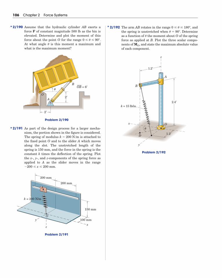
2/192 The arm AB rotates in the range andthe spring is unstretched when Determineas a function of the moment about O of the springforce as applied at B. Plot the three scalar compo-nents of and state the maximum absolute valueof each component.
Problem 2/192
A
z
D
B
k = 15 lb/in.
Ox
y
1.2′
1.2′
2.4′
θ
MO,
�
� � 90�.0 � � � 180�,
106 Chapter 2 Force Systems
2/190 Assume that the hydraulic cylinder AB exerts aforce F of constant magnitude 500 lb as the bin iselevated. Determine and plot the moment of thisforce about the point O for the range At what angle is this moment a maximum andwhat is the maximum moment?
Problem 2/190
2/191 As part of the design process for a larger mecha-nism, the portion shown in the figure is considered.The spring of modulus is attached tothe fixed point O and to the slider A which movesalong the slot. The unstretched length of thespring is 150 mm, and the force in the spring is theconstant k times the deflection of the spring. Plotthe x-, y-, and z-components of the spring force asapplied to A as the slider moves in the range
mm.
Problem 2/191
150 mm
200 mm
200 mm
100 mmyO
xz
k = 200 N/m
A
�200 � x � 200
k � 200 N /m
2′
B
θ
O
2′
A
= 6′OB–––
�
0 � � � 90�.
*
**

503
Absolute system of units, 10Acceleration, of a body, 8, 121
due to gravity, 11Accuracy, 13Action and reaction, principle of, 8, 25, 110, 173, 204, 225, 279Active force, 402Active-force diagram, 403Addition of vectors, 6, 25, 28, 482Aerostatics, 306Angle, of friction, 339
of repose, 342Approximations, 14, 254Archimedes, 3Area, first moment of, 238
second moment of, 238, 441Area moments of inertia, see Moments of inertia of areasAtmospheric pressure, 307Axes, choice of, 27, 68, 114, 179, 237, 240
rotation of, 465Axis, moment, 38, 74
Beams, concentrated loads on, 273definition of, 272distributed loads on, 273external effects, 273internal effects, 279loading-shear relation for, 280, 281resultant of forces on cross section of, 279shear-moment relation for, 280, 281, 284statically determinate and indeterminate, 272types of, 272
Bearing friction, 368Belt friction, 377Bending moment, 279Bending-moment diagram, 280Bodies, interconnected, 204, 402Body, deformable, 5
rigid, 4Body force, 24, 234Boundary conditions, 293British system of units, 9Buoyancy, center of, 312
force of, 312principle of, 311
Cables, catenary, 295flexible, 291length of, 294, 297parabolic, 293tension in, 294, 297
Cajori, F., 7Center, of buoyancy, 312
of gravity, 25, 235of mass, 235, 237of pressure, 308
Centroids, 238of composite figures, 254by integration, 238
of irregular volumes, 255table of, 497by theorems of Pappus, 264
Coefficient, of friction, 338, 339, 495of rolling resistance, 378
Collinear forces, equilibrium of, 121Components, of a force, 26, 27, 28
rectangular, 6, 26, 27, 28, 66scalar, 27of a vector, 6, 26, 27, 28, 66
Composite areas, moment of inertia of, 456Composite bodies, center of mass of, 254Composite figures, centroid of, 254Compression in truss members, 175, 178Computer-oriented problems, 17, 104, 168, 229, 331, 392,
438, 475Concentrated forces, 24, 233
on beams, 273Concurrent forces, equilibrium of, 121, 146
resultant of, 25, 28, 59, 89Cone of friction, 340Constant of gravitation, 12, 496Constraint, 124, 148
adequacy of, 125, 149partial, 149proper and improper, 125redundant, 126, 149
Coordinates, choice of, 27, 67, 114, 240, 325, 443Coplanar forces, equilibrium of, 121, 122
resultant of, 28, 58Coulomb, 336Couple, 50, 76
equivalent, 50moment of, 50, 76resolution of, 51, 89resultant, 58, 88, 89vector representation of, 50, 76work of, 399
Cross or vector product, 39, 74, 483
D’Alembert, J., 3da Vinci, 3Deformable body, 4Degrees of freedom, 404, 422, 433Density, 237, 495Derivative of vector, 484Derivatives, table of, 485Diagram, active-force, 403, 419
bending-moment, 280free-body, 16, 110, 114, 146shear-force, 280
Differential element, choice of, 239Differentials, order of, 13, 239, 325Dimensions, homogeneity of, 17Direction cosines, 7, 66Disk friction, 369Displacement, 398
virtual, 400
Index

specifications of, 24unit of, 9work of, 398
Force–couple system, 51, 58, 77Force system, concurrent, 59, 76, 89, 121, 146
coplanar, 58general, 23, 89parallel, 26, 59, 89
Formulation of problems, 14Frames, defined, 204, 225
equilibrium of, 204Frames and machines, rigidity of, 204Free-body diagram, 16, 110, 114, 146Freedom, degrees of, 404, 422, 433Free vector, 5, 6, 50, 76Friction, angle of, 339
bearing, 368, 369belt, 377circle of, 368coefficients of, 338, 339, 495cone of, 340disk, 369dry or Coulomb, 336, 337fluid, 336internal, 336journal bearing, 368kinetic, 338limiting, 338in machines, 357mechanism of, 337pivot, 369problems in dry friction, 341, 387rolling, 378screw thread, 358static, 338types of, 336wedge, 357work of, 404
Gage pressure, 307Galileo, 3Gas, 306Graphical representation, 15, 25, 26, 58Gravitation, constant of, 12, 496
law of, 12Gravitational force, 12, 25, 113, 234Gravitational potential energy, 418Gravitational system of units, 10Gravity, acceleration due to, 11
center of, 25, 235Guldin, Paul, 264Gyration, radius of, 443
Homogeneity, dimensional, 17Hydrostatic pressure, 307, 309, 310Hydrostatics, 306Hyperbolic functions, 296
Ideal systems, 402Impending motion, 338, 340, 341Inclined axes, area moments of inertia about, 465Inertia, 4, 442
area moments of, see Moments of inertia of areasprincipal axes of, 466products of, 464
Inertia force, 442Integrals, table of selected, 486Integration, choice of element for, 240, 325
numerical techniques for, 491, 493of vectors, 485
504 Index
Distributed forces, 24, 233, 234, 325, 326on beams, 273
Distributive laws, 40, 483Dot or scalar product, 67, 398, 483Dynamics, 4, 8
Efficiency, mechanical, 405Elastic potential energy, 417Energy, criterion for equilibrium, 422
criterion for stability, 422elastic, 417potential, 417, 419, 421
Equilibrium, alternative equations of, 123categories of, 121, 146of collinear forces, 121of concurrent forces, 121, 146condition of, 58, 121, 145, 401, 403of coplanar forces, 121, 122energy criterion for, 421, 422equations of, 121, 145of interconnected rigid bodies, 204, 402of machines, 204necessary and sufficient conditions for, 121, 145neutral, 421of parallel forces, 121, 148of a particle, 401of a rigid body, 401stability of, 125, 421with two degrees of freedom, 404by virtual work, 400, 401, 403
Euler, 3External effects of force, 24
First moment of area, 238Fixed vector, 5, 24Flexible cables, 291
differential equation for, 292Fluids, 306
friction in, 336incompressible, 307pressure in, 306
Foot, 9Force, action of, 23, 111, 112, 146, 147
active, 402body, 24, 234buoyancy, 312components of, 26, 27, 66concentrated, 24, 233concept of, 4contact, 24coplanar system of, 58distributed, 24, 233, 234, 325, 326effects of, 23external, 24friction, 113, 335gravitational, 12, 25, 113, 234inertia, 442intensity of, 234internal, 24, 234, 279, 403kinds of, 24magnetic, 24, 113measurement of, 25mechanical action of, 111, 112, 147moment of, 38, 74polygon, 58, 123reactive, 24, 402remote action of, 113resolution of, 26, 27, 66, 67resultant, 58, 88, 89, 235, 325shear, 279, 306

Interconnected bodies, 204, 402Internal effects of force, 24, 234, 279, 403Internal friction, 336International System of units, 9
Joints, method of, 176, 198, 224Joule, 400Journal bearings, friction in, 368
Kilogram, 9, 10, 12Kilopound, 10Kinetic friction, 338
coefficient of, 339, 495
Lagrange, 3Laplace, 3Law, associative, 482
commutative, 482, 483of cosines, 482distributive, 40, 483of gravitation, 12parallelogram, 6, 25, 58of sines, 482Pascal’s, 306triangle, 6, 25
Laws of motion, Newton’s, 7Length, standard unit of, 10Limit, mathematical, 14Line of action, 24Liquids, 307Loading-shear relation for beams, 280, 281
Mach, Ernst, 40Machines, defined, 204, 225
equilibrium of, 204friction in, 357ideal or real, 336
Mass, 4, 10center of, 235, 237unit of, 9, 10
Mathematical limit, 13Mathematical model, 15Mathematics, selected topics in, 479Mechanical efficiency, 405Mechanical system, 110Mechanics, 3Metacenter, 313Metacentric height, 313Meter, 10Method, of joints, 176, 198, 224
of problem solution, 16, 99, 114, 163, 224, 325, 387, 433of sections, 188, 198, 224of virtual work, 397
Metric units, 9Minimum energy, principle of, 405Mohr’s circle, 469Moment, bending, 279
components of, 75of a couple, 50, 76of a force, 38, 74torsional, 279, 442units of, 38vector representation of, 39, 74
Moment arm, 38Moment axis, 38, 74Moments, principle of, 59, 88, 235, 241, 325Moments of inertia of areas, 441
for composite areas, 456dimensions and units of, 443about inclined axes, 465by integration, 442
Index 505
maximum and minimum, 466, 467Mohr’s circle representation of, 467polar, 443principal axes of, 466radius of gyration for, 443rectangular, 442table of, 497tabular computation of, 456transfer of axes for, 444, 464
Morin, 336Motion, impending, 338, 340, 341Multi-force members, 204
Neutral equilibrium, 421Newton, Isaac, 3Newton’s laws, 7Newton (unit), 9Newton’s method, 489Numerical integration, 491, 493
Order of differentials, 13, 239, 325
Pappus, 264theorems of, 264
Parallel-axis theorems, for area moments of inertia, 445Parallel forces, equilibrium of, 121, 148
resultant of, 26, 59, 89Parallelogram law, 6, 25, 58Particle, 4Particles, equilibrium of, 401Pascal (unit), 234Pascal’s law, 306Pivot friction, 369Polar moment of inertia, 443Polygon, of forces, 58, 123Potential energy, 417, 419, 421
datum for, 418units of, 418, 419
Pound, standard, 10Pound force, 9Pound mass, 10Pressure, 234, 306
atmospheric, 307center of, 308fluid, 306gage, 307hydrostatic, 307, 309, 310on submerged surfaces, 307, 309, 310
Principal axes of inertia, 466Principia, 7Principle, of action and reaction, 8, 25, 110, 173, 204,
225, 279of buoyancy, 311of concurrency of forces, 122of minimum energy, 421of moments, 59, 88, 235, 241, 325of transmissibility, 5, 24, 58of virtual work, 401, 403, 420
Products of inertia, 464about inclined axes, 465
Products of vectors, 39, 67, 74, 75, 398, 483
Radius of gyration, 443Reactive forces, 24, 402Rectangular components, 6, 26, 27, 28, 66Rectangular moments of inertia, 442Redundancy, external and internal, 178, 197Redundant supports, 125, 149Repose, angle of, 342Resolution, force, 26, 27, 66, 67
force and couple, 51, 58, 77

of derivatives, 485of mathematical relations, 479of solar system constants, 496
Tension in truss members, 175, 176Theorem, of Pappus, 264
of Varignon, 39, 59, 75Three-force member, 122Thrust bearing, friction in, 369Time, 4, 10Ton, 10Torque, see Moment, of forceTorsional moment, 279, 442Transfer of axes, for moments of inertia, 444
for products of inertia, 464Transmissibility, principle of, 5, 24, 58Triangle law, 6, 25Triple scalar product, 75, 484Triple vector product, 484Trusses, definition, 175
plane, 175simple, 175, 197space, 197, 224stability of, 178, 197statical determinacy of, 178, 197, 224types of, 174
Two-force members, 122, 175
U.S. customary units, 9Units, 8, 38, 400Unit vectors, 7, 27, 66, 68, 75Unstable equilibrium, 421
Varignon, 3Varignon’s theorem, 39, 59, 75Vector equation, 8Vectors, 4, 23
addition of, 6, 25, 28, 482components of, 6, 26, 27, 28, 66couple, 50, 76cross or vector product of, 39, 74, 483derivative of, 484dot or scalar product of, 67, 398, 483fixed, 5, 24free, 5, 6, 50, 76moment, 39, 74notation for, 5resolution of, 26, 27, 66, 67sliding, 5, 24, 38, 76subtraction of, 6, 482unit, 7, 27, 66, 68, 75
Vector sum, of couples, 76, 88of forces, 25, 28, 58, 88
Virtual displacement, 400Virtual work, 397, 400
for elastic systems, 420for ideal systems, 402, 403for a particle, 401for a rigid body, 401
Viscosity, 336
Wear in bearings, 369Wedges, friction in, 357Weight, 12, 25, 113, 234Work, of a couple, 399
of a force, 398units of, 400virtual, 397, 400
Wrench, 89
506 Index
Resultant, of concurrent forces, 25, 28, 59, 89of coplanar forces, 28, 58couple, 58, 88, 89of fluid pressure, 307, 309, 311force, 58, 88, 89, 235, 325of forces on beam cross section, 279of general force system, 89of parallel forces, 26, 59, 89
Right-hand rule, 38, 67, 74, 483Rigid bodies, interconnected, 204, 402Rigid body, 4
equilibrium of, 401Rolling resistance, coefficient of, 378
Scalar, 4Scalar components, 27Scalar or dot product, 67, 398, 483Screw, friction in, 358Second moment of area, 238, 441Sections, method of, 188, 198, 224Series, selected expansions, 485Shear force, 279, 306Shear-force diagram, 280Shear-moment relation for beams, 280, 281, 282Shear stress, 442Singularity functions, 282SI units, 9Sliding vector, 5, 24, 38, 76Slug, 9Space, 4Space trusses, 197, 224Specific weight, 234Spring, linear and nonlinear, 112, 113
potential energy of, 417stiffness of, 417
Stability, of equilibrium, 125, 421of floating bodies, 312for single degree-of-freedom system, 421of trusses, 178, 197
Statically determinate structures, 125, 148, 173, 178, 197Statically indeterminate structures, 125, 149, 178, 197, 204Static friction, 338
coefficient of, 338, 495Statics, 4Stevinus, 3Stiffness of spring, 417Stress, 234
shear, 442Structures, statical determinacy of, 125, 148, 173, 178, 197, 204
types of, 173Submerged surfaces, pressure on, 307, 309, 310Subtraction of vectors, 6, 482Symmetry, considerations of, 237, 464System, with elastic members, 417
force–couple, 51, 58, 77of forces, concurrent, 25, 59, 75, 89, 121, 146
coplanar, 58general, 23, 88parallel, 59, 89, 121, 148
ideal, 402of interconnected bodies, 204, 402mechanical, 110real, 404of units, 8
Table, of area moments of inertia, 497of centroids, 497of coefficients of friction, 495of densities, 495

507
Problem Answers
Chapter 1
1/1 , , 1/2 units,1/3 units,1/4 , , 1/5 slugs, kg1/6 ,1/7 , slugs, kg1/8 ,
,
1/9 ,1/101/11 ,
,, nt � �4.09%ns � 2.06%� � 20�:
nt � �1.017%ns � 0.510%� � 10�:nt � �0.254%ns � 0.1270%� � 5�:
F � 1.358(10�9) NF � 4.46(1019) lbF � 1.984(1020) N
A/B � 3.86AB � 11.51A � B � 4.94A � B � 8.40
m � 58.9m � 4.04 W � 578 NW � 184.1 lbW � 819 N
m � 1361m � 93.2�z � 68.2��y � 138.0��x � 56.1�
�x � 162.6�V� � 14.67�x � 83.0�V � 16.51
n � 0.8i � 0.6j�y � 126.9��x � 36.9�
Chapter 2
2/1 , , 2/2
2/3 kN2/4 lb, lb2/5 N2/6 ,
,2/7
2/8 N2/9 lb2/10 (a) N, N
(b) N, N2/11 kips
2/12 ,
2/13 kN, kN2/14 N, N2/15 kN, kNFn � 1.532Ft � 1.286
R � 693R � 600i � 346jR � 9.25T � 5.83
Fn � �F�r2 � s2
rFt �Fsr
R � 2.35i � 3.45jFt � 98.5Fn � �17.36
Ft � 94.0Fn � 34.2� � 49.9�, R � 1077Fn � �62.9 N, F � 97.9
R � 3.80 kN, � � 338� (or �21.6�)Ft � F cos (���)Fn � F sin (���)
Fy � �F cos �Fx � �F sin �F � �1080i � 1440j
Fy � 1412Fx � 2650i � 2.5jF � �6
Fx � �346i lb, Fy � 200j lbFx � �346 lb, Fy � 200 lbF � �346i � 200j lb
F � 460i � 386j NFy � �386 NFx � 460 N
(When a problem asks for both a general and a specific result, only the specific result might be listed below.)

508 Problem Answers
2/16
2/17 N, N2/18 lb,2/19 N2/20 N, N, N2/21 lb, lb
lb, lb2/22 kN, kN
kN, kN2/23 (a) N,
(b) N2/24 lb, lb2/25 ,2/26 ,2/27 ,2/28 N, N
N, N2/29 N, N2/30 N, N2/31 CCW,
and2/32 CW2/33 N
2/34 CW
2/35 CW2/36 CW2/37 lb-ft CW2/38 CW
2/39 CW
2/40 CWCW
2/41 lb-in. CCW2/42 CCW2/43 lb-ft CCW2/44 CW
CW
2/45
2/46 lb-in. CCW2/472/48 CCW2/49 lb-in. CW, lb2/50 CCW2/51 lb-ft CCW2/52 lb-in. CW
2/532/54 lb-ft2/55 CCW2/56 ,2/57 CW2/58 CW
, CW2/59 lb-in. CW2/60 CW
CW2/61 m2/62 N2/63 CCW2/64 lb2/65 , lb-in. CCW2/66 , CCW2/67 kN
2/68 (below A)
2/69 lb2/70 N2/71 CW2/72 , CCW2/73 N, CW2/74 , CW2/75 CCW
2/76 , CW
2/772/78 , CCW2/79 , lb2/802/81 (a) ,
(b) , (c) ,
2/82 (a) along
(b)
(c)
2/83 left of A2/842/852/862/87 kN m CCW2/88 CCW2/89
ft2/90 below Od � 4 m
MA � 18,190 lb-ft CW, x � 6.05R � 400i � 3010j lbM � 148.0 N � m
�R � 1.644i � 1.159j kN, MA � 2.22y � �10 in.R � 80 N left, y � 40 mmR � 3 kN down, x � 4.33 md � 10.70 m
R � �Fi ��3Fj along y � ��3 x �
d2
R � �2Fi along y �
3d4
y � �d2
R � 2Fi
MO � 0R � �Fi � FjMO � FdkR � 0
MO � 0R � �2FjR � 17.43 kN at �x � 26.1�
F � 1361� � 56.9�
MO � 0.462FRF at 67.5�
y � �40.3 mm
MB �3hbF
4�b2
4� h2
F � F �b2
i � hj
�b2
4� h2�
M � 21.7 N � mMC � 174.9 N � mR � 250 N at �45�
MO � 60.0 N � mF � 43.4i � 246jMO � 17.29 N � mR � 50 N at 110�
M � 2.60 N � mF � 231F � 700
d �MA�b2 � h2
Rb
P � 51.4MO � 0.75 kN � mR � 10 kN down
MO � 14.85R � 7 lb at 60�
F � 875M � F(b cos � � h sin �)F � 16.18yA � �0.4MB � 76.0 kN � m
kN � mMO � 24F � 12 kN at 30�,M � 1440
(MO)max � 41.6 N � m� � 33.2�
MO � 41.5 N � mMO � 0.902 kN � m
R � 220 lb at 94.6�FDE � 141.6 lbMO � 26.8 N � mMO � 80.2k� � 57.5�
� � 65.8�, MO � 740MO � 5010MO � 23.5 N � m
T � 64.3MO � 128.6MO � 0.866 N � mMO � 0.1335 � 0.0282s N � mmMO � 130
� � tan�1�hb�
MP � Tr[cos � � sin (� � �)]MO � Tr sin (� � �)MO � 102.8MO � 191.0 N � mMO � 0.268MA� 81.9 N � mMB � 48 N � m
MO � mgb�1 �2��
MO � 5.64 N � mMO � 70.0
N � mMO � 43.4MO � 46.4 N � m
MO �Fbh
�b2 � h2
T � 36MB � 83.2 lb-ft
(0, 0.78)m(x, y) � (�1.3, 0)MO � 2.68k kN � mMO � 2.68 kN � m
Ft � �39.2Fn � 50.4Fy � 194.4Fx � �101.2Pn � 63.6AB: Pt � 63.6
Pn � 45.0BC: Pt � �77.9� � 18.19�� � 51.3�
Tt � �672 NTn � 333 N� � 18.19�� � 51.3�
T � 800P � 537R � 520i � 700j
� � 36.6�R � 872Pb � 3.76Pa � 3.63Fb � 2.39Fa � 1.935
Pb � 207Pa � 400Fb � 980Fa � 1093
Pa � 693Rb � 622Ra � 1170R � 88.8i � 245j
� � 84.3�R � 50.2Tt � 74.5Tn � 66.7
Ty �T(sin � � 1)
�3 � 2 cos � � 2 sin �
Tx �T(1 � cos �)
�3 � 2 cos � � 2 sin �
�
�

Problem Answers 509
2/91 CW
2/922/93
2/94
2/952/96
2/97
2/98
2/992/100
2/1012/102
2/1032/1042/105
2/1062/1072/1082/109
2/110
2/1112/112
2/1132/1142/1152/1162/117
2/118
2/119
2/120
Fy �2bcF
�a2 � b2� a2 � b2 � 4c2
Fx �2acF
�a2 � b2� a2 � b2 � 4c2
T � 191.0i � 28.7j � 51.8k lb, Txz � 197.9 lb� 2 cos �k]
(cos �i � sin �j)F �F
�5 – 4 sin � [(2 sin � � 1)
TDC � 458 NT � 500(0.370i � 0.410j � 0.833k) NTCD � 46.0 NT � 778 lb, �xy � 8.88�
TBC � 251 N� � 54.9�
�x � 82.0�, �y � 165.6�, �z � 78.0�
T � 110.7i � 775j � 166.0k lbT � �598i � 411j � 189.5k N
FCD ��65
kN, � � 56.8�
Fx � 390 lb, Fy � �244 lb, Fz � 195.2 lbF � 500[0.781i � 0.488j � 0.390k] lbTGF � 0.978 kNT � 0.321i � 0.641j � 0.962k kNF � 92.7i � 61.8j � 61.8k NTAC � 2.06 kNT � 0.876i � 0.438j � 2.19k kN�x � 155.7�, �xz � 13.17�
T � 2(�0.920i � 0.383j � 0.0767k) kNFx � 2.05 kN, FOA � 3.55 kNF � 2.05i � 3.55j � 2.87k kN
Fy � 403 lbF � 791i � 403j � 146.5k lb,y � �1.547x � 29.6 (in.)
MO � �358k lb-in.R � 12.10i � 18.71j lb,FC � FD � 6.42 N, FB � 98.9 NMG � 460 lb-ft CCW, x � 4.06 ftR � 185i � 1133j lby � �0.253 mR � 903i � 175j N, x � 1.308 m
y � �13
x �110
3 (in.)
R � 45i � 15j lb, MA � �1650k lb-in.x � 7.83 mm, y � 14.55 mmMA � 11 000 N � m CW, x � 5 mR � 346i � 2200j Ny � �23.4 mR � �15i � 47.3j kN, x � 7.42 mx � 1.637 m, y � �0.997 mx � �10.39 mR � T(1.966i � 0.259j), MO � 2.69T
�
�
��
2/1212/1222/123
2/1242/1252/1262/127
2/128
2/1292/130
2/1312/1322/133
2/134
2/1352/1362/1372/138
2/1392/140
2/141
2/142
2/143
2/1442/145
,2/146
2/147
2/148
2/149 L � 1 oz, � � 30�, R � 5.82 ozM� � 685 lb-in.MO � 136.4i � 679k lb-in.
MO �Fh�5
(cos �j � sin �i)
F �F�5
(cos �i � sin �j � 2k)
MO � �9.04i � 414j � 75.0k N � mMz � 75.0 N � m
MBC � 2540 lb-in.MC � �2840k lb-in.MB � �1871i � 1080j � 3780k lb-in.MO � �260i � 328j � 88k N � mMAB � �4.05i � 2.34k lb-in.MA � �5.40i � 4.68j lb-in.Mz � �0.962k kN � mMO � �2.89i � 0.962k kN � m(Mx)W � �31.1 N � m, MOB � 0Mx � 31.1 N � mM � 5.15i � 90k kN � mF � �1.716j � 28.3k kNF � 228 NMO � 643i � 766j � 6250k N � mmR � �38.3i � 32.1j NMO � �48.6 j � 9.49k N � m, d � 74.5 mmM � 3400i � 51 000j � 51 000k N � mM � �60i � 48k lb-in.MO � �361i � 718j � 419k N � mR � �598i � 411j � 189.5k NMx � �98.7 N � mMO � �98.7i � 17.25j � 29.9k N � mMO � 480i � 2400k N � m
MO � �ag(b �a2)[�sin �i � cos �j]
MOA � �690 lb-in.MO � �90.6i � 690j � 338k lb-in.Mz � 208k lb-in.
MO ��g2 (a2j � b2i)
M � �75i � 22.5j N � mMO � 2.81 kN � mM � (126i � 36j � 50.6k)103 lb-in.M � (�0.450i � 0.300j)106 lb-in.
MOB � �Fac
a2 � b2(ai � bj)
MO � F(�ci � ak), MA � FakMO � �320i � 160j lb-ft, MO � 358 lb-ft
M2 � F2(cj � bk), M3 � �bF3kM1 � �cF1j,
Fz � F � a2 � b2
a2 � b2 � 4c2

510 Problem Answers
2/185 T �
12.5�� ��
4��d2 � 80d cos�� ��
4� � 3200 sin�� ��
4� � 3200
d sin�� ��
4� � 40 cos�� ��
4�
2/150
2/151
2/1522/153
2/154
2/155 ,2/1562/157
, no2/158
2/1592/160
2/161
2/162
2/163
2/164
2/165
2/166 ,
2/167
2/168
2/1692/1702/1712/1722/1732/1742/1752/176
x � 15.5 in.R � 80 lb down, MA � 1240 lb-in. CWd � 0.733 mMO � 189.6 N � m CCWx � 266 mmF � 300 lbM1 � �cF1i, M2 � F2(ci � ak), M3 � �aF3kF � 20.7 lb, Fx � �5.36 lbTB � �TA � �1.664i � 1.109 kNx � 0.221 m, y � �0.950 mR � 44.7 kN, M � �26.9 kN � m
x � a � c, y �b2
, M �Fb2 (i�k)
M � �99.6 N � mx � 66.9 mm, z � 0
y �a10
, z � 2a
M �3aF10 (i � 3k)R � F(i � 3k),
y � 0, z �7a2
, M � �aT2 (i � j)
x � �6.4 in., y � 1.4 in.R � �20j � 40k lb, MO � �56i � 320j lb-in.MO � 1153i � 830j � 250k lb-in.R � 25i � 60j � 43.3k lbM � �0.4i � 4j � 4k kN � m, M � 5.67 kN � mR � 4i � 3j � 6k kN, R � 7.81 kNx � 8 ft, z � �2 ftR � 600j lb, MO � 1200i � 4800k lb-fty � �4 m, z � 2.33 mM � 45.3j � 40.9k kN � mR � �20i � 37.9j � 12.65k kNMO � �48.9j � 114.5k N � mR � �266j � 1085k NR � �8i kN, MG � 48j � 820k kN � m
MG � �30i � 72k lb-in.R � �1.2j lbMO � 12i � 300j � 1200k N � mR � 1000j � 500k N
yesMO � Fb(1.866i � 0.268j � k),R � F(0.5j � 0.1340k)x � 2.92 m, y � 6.33 mx � �b, y � 4bR � Fk, MO � Fb(4i � j)MO � �216i � 216j N � m, R ⊥ MO
R � 600 N down 2/1772/1782/179
,
2/180
2/181 ,2/1822/1832/184 � � 21.7�, T � 1.022 kN
R � 1093 lb, M � 9730 lb-ftM � �20i � 6.77j � 37.2k N � m
Mz � �45.0 N � mT � 282i � 112.7j � 398k N
F � F�hi � r(cos � � 1)j � r sin �k
�h2 � 2r2(1 � cos �) �(c) TAO � 2.69 kN(MO)z � 0
(MO)y � �10.90 kN � m(MO)x � 7.63 kN � m(b) MO � 7.63i � 10.90j kN � m(a) TAB � �2.05i � 1.432j � 1.663k kNM � 864i � 6720k lb-in., M � 6770 lb-in.R � 4.75 kN, MA � 21.1 kN � m CCW
2/186
2/187
2/188
2/189
2/190
2/191
2/192
(Mz)max � 47.6 lb-ft at � � 0 and � � �
(Mx)max � 95.1 lb-ft at � � 0 and � � �
259 cos �k] lb-ft
[�518i �MO ��1.5 – 0.5 sin � � 1
�1.5 – 0.5 sin �
Fz � [�x2 � 0.0325 � 0.15]� 30�x2 � 0.0325 �
Fy � [�x2 � 0.0325 � 0.15]� 20�x2 � 0.0325 �
Fx � [�x2 � 0.0325 � 0.15]� �200xA
�x2 � 0.0325 �(MO)max � 1414 lb-ft at � � 16.87�
MO �3000(sin � � cos �)
�11 � 6(sin � � cos �)k lb-ft
MO ��76.8 cos �i � 38.4 cos �j � 38.4 sin �k
�1.44 – 1.28 sin �
MA � 154.8 sin � � 79.7 cos � (lb-in.)MB � 104 sin(� � 50�) (lb-in.)
M �90 cos �[�0.34 � 0.3 sin ��0.65]
�0.34 � 0.3 sin �
(MO)max � 0.5FR at � � 60�
Chapter 3
3/13/23/33/43/5
3/63/73/83/9 (a)3/10 (a)3/11 m � 1509 kg, x � 1052 mm
P � 6.00 N, (b) P � 6.25 NP � 5.59 N, (b) P � 5.83 N
T � 131.2 lbW � 162 lbOx � 0, Oy � 1736 N, MO � 7460 N � m CW
MO � 7560 N � m CCWOx � 1500 N, Oy � 6100 NAy � 1864 N, By � 2840 NNA � 15.91 lb, NB � 13.09 lbNA � 12 lb down, NB � 24 lb upFA � 566 N, FB � 283 N
*
*
*
*
*
*
*
*
*
�
�

Problem Answers 511
3/123/133/143/153/163/173/183/193/203/213/223/233/243/25 (a)3/263/273/283/293/303/31 CW3/323/333/343/353/363/373/383/393/403/413/423/433/443/453/46 (a)
(b)3/473/483/493/503/513/523/533/54
3/55
3/563/573/583/59
3/60 (a)(b)
3/61
3/623/633/643/653/66
3/673/68
3/69
3/703/71
3/72
3/73
3/743/75
3/76
3/773/783/793/803/813/82
3/833/843/85
3/863/873/883/893/90
If P = Pmin/2: D = 13.5 N3/913/92 P � 0.206 N, Ay � 0.275 N, By � �0.0760 N
A � 31.4 lb, B � 72.1 lb
Pmin � 18 N, B � 30.8 N, C � 29.7 NC � 100 lb, Bxy � 45.5 lb, Axy � 38.0 lbB � 2.36 kN�NA � 1000 N, �NB � �NC � �500 Nk � 16.41 lb /in.NA � 15.58 lb, NB � 12.95 lbP � 2.72 lb, FA � 1.896 lb, FB � 0.785 lbR � mg/�7FS � 3950 N, FA � 437 N, FB � 2450 NMz � 341 N � m
My � 8700 N � mMx � �524 N � m,Ox � 869 N, Oy � 0, Oz � 2440 N� � 30�
T � 452 lb, T0 � 267 lbTA � TB � 5.41 kN, TC � 9.87 kN�NA � 66.1 N, �NB � 393 N, �NC � 522 NA � 275 lb, B � 158.5 lb, C � 317 lb
Mz ��gh
2 (ab � ac � c2)
Mx � �ghb�b2
� c�, My � 0
Ox � 0, Oy � �gh(a � b � c), Oz � 0
� � 9.49�, X � 118.0 mmAx � 48 lb, Bx � 12 lb
TBD � 2770 N, TBE � 654 NTAC � 4810 N,Ox � 1962 N, Oy � 0, Oz � 6540 NMz � 0
Mx � �ga�a2
� b � c�, My � ��gb�b2
� c�Ox � 0, Oy � 0, Oz � �g(a � b � c)D: NA � 3140 N, NB � 4710 N, ND � 7850 NC: NA � 2350 N, NB � 5490 N, NC � 7850 Nm � 1509 kg, x � 1052 mm, y � �20.5 mm
O � �g(a � b � c), M ��g2 �a4
4�
b4
9
O � 300 lb, M � 8280 lb-ftT1 � 4.90 kNMx � 81.4 lb-ft, My � 9.76 lb-ftOx � 1.953 lb, Oy � �16.27 lb, Oz � 16.27 lbTA � TB � 278 N, TC � 262 NTAB � TAC � 1698 N, D � 1884 NTA � TB � 20.4 lb, TC � 27.2 lbTAB � TAC � 47.8 lb, TAD � 31.2 lbM � �9.32i � 21.7j � 34.8k N � mR � �173.9i � 46.6k N
S � 2.20W, C � 2.53WS � 0.669W, C � 0.770W
M � 49.9 sin � (N � mm) CWA � 1266 N, B � 1514 NF � 187.1 lbAx � 346 N, Ay � 1100 N, Fy � 1100 N
C �mg2
(�3 �2�), FA � 1.550mg
O � 820 lbT � 0.1176kL � 0.366mgP � 26.3 NF � 121.7 lbM � 4.94 kN � m CCWRB � 1382 N, O � 2270 NO � 4140 N, P � 2.58(106) PanA � �32.6%, nB � 2.28%
nA � 3.15%, nB � �5.97%nA � �4.14%, nB � 4.98%
M � 41.5 lb-ft, F � 35.3 lbC � 1276 lb, P � 209 lb /in.2P � 45.5 N, R � 691 NF � 2.25W, O � 2.67W
F � 753 N, E � 644 NFD � 710 N, Ox � 662 N, Oy � �185.6 NF � 1832 N
A � 1.082 kNR � 4.38 kNNC � 18 lbB � 133.3 N, C � 253 NP � 166.7 N, T2 � 1.917 kNNA � 0.892mg, O � 0.580mgNC � 0.433mg, O � 0.869mgAx � 869 N, Ay � 2350 N, MA � 8810 N � mT � 200 lb, A � 188.8 lbWL � 550 lbF � 13.98 N, O � 48.8 NDx � L, Dy � 1.033L, Ay � 1.967LP � 111.1 N
FC � 1705 N, (b) FC � 1464 NT � 38.3 lb, CD � 5.23 ftNA � NB � 12.42 kNO � 64.6 lbP � 40 lbF � 52.8 Nm1 � 0.436mNA � 0.1091mg, O � 1.006mgT � 90 N, O � 94.9 NT � 160 N� � 18.43�
T � 81.2 lbTAC � 215 N, TBC � 264 NP � 225 N �

512 Problem Answers
3/933/943/95
3/963/97
3/983/99 L = 1.676 kN3/1003/1013/1023/103
3/104
(a) (b)
3/1053/1063/1073/1083/109 ,3/1103/1113/1123/113
3/114
3/1153/116
3/117
3/118
3/119 (a)
(b)
(c)3/120
3/121
3/122
3/1233/124
3/125
3/126 T � 495 N at � � 15�
T �51.1 cos � � 38.3 sin �
cos ��425 – 384 sin �
T � 0 at � � 1.729�
T45� � 5.23 N, T90� � 8.22 NTAB � 503 lb, TBC � 493 lb, TCD � 532 lbAB � 17.01 ft, CD � 8.99 ftTAB � 529 lb, TBC � 513 lb, TCD � 539 lb� � 14.44�, � � 3.57�, � � 18.16�
(TBC)max � 600 N at x � 6.09 m(TAC)max � 600 N at x � 3.91 m
Rmax � 24.3 kN at x � 3.8 m
Rmin � 10.39 kN at x �12
m
R �13
[400x2 � 400x � 1072]12
�max � 79.1�
[8 � 8 cos (� � 60�)]12
�T � �2750 cos � � 687 cos (� � 60�)4 sin (� � 60�) �
T � mg
�32
cos ���24
cos (� � 15�) cos �
Mz � 857 N � mMx � �19 390 N � m, My � �12 120 N � mOx � �14 900 N, Oy � 24 400 N, Oz � 8890 NA � 183.9 N, B � 424 N
P �mg
3�2
FA � 24.5 lbT � 1053 NTA � 147.2 N, TB � 245 N, TC � 196.2 Nx� 199.2 mm
�T � 344 N�F � 521 ND � 7.60 kNA� � 41.7 lbT1 � 45.8 kN, T2 � 26.7 kN, A � 44.2 kNFA � 486 N down, FB � 686 N up
m1 �32
mm1 � 0.634m,
NA � �3g �m2
�m1
3 �NA � 159.9 lb down, NB � 129.9 lb upP � 351 NA � 15 lb, B � 40 lb, T � 60.2 lbR � 566 N
T � 471 N, O � 144.9 NNB � 32.4 NP � 50 N, NC � 58.1 N, NA � 108.6 NT � 277 N, B � 169.9 N Mz � �2.56 N � m, Bz � 14.72 NMx � �1.857 N � m, My � 1.411 N � mM � 47.7 N � m, V � 274 N, P � 321 NFB � 70 lb, Dn � 101.1 lb
Chapter 4
*
*
*
*
*
*
**
*
*
�
�
�
�
�
�
BH � DF � CG � 60 kN T, CH � CF � 48.0 kN C
4/1
4/2
4/3
4/4
4/54/6
4/7BC � CD � 75 kN CAB � DE � 96.0 kN C, AH � EF � 75 kN TBC � 2 kN T, DE � 1 kN CAE � BD � 1.414 kN CAB � BE � CD � 1 kN TAC � 849 lb C, AD � 849 lb C, DE � 849 lb T
CD � 15 kN CBC � 5�2 kN C AD � 0,AB � 5 kN T, AC � 5�5 kN TBC � 0.816W CAB � 1.115W T, AC � 0.577W TBC � 1962 N CAB � 3400 N T, AC � 981 N TBC � 2550 N CAB � 2350 N T, AC � 981 N T 4/9
4/10
4/11
4/12
4/13
,
4/14
, DE �113
�3 kN TCD �133
�3 kN T
BE �73�3 kN C
BC �263
�3 kN C, BD � 3�3 kN C
AB � 9�3 kN C, AE � 5�3 kN T
DE � 1400 /�3 lb CBE � BD � 800 /�3 lb TAB � BC � 1000 /�3 lb TAE � CD � 2000 /�3 lb CCE � 12.62 kN T, DE � 7 kN TBE � CD � 12.62 kN C, BC � 2.00 kN TAB � 6.61 kN T, AE � 21.0 kN T
AB � BC �L2
T, BD � 0
DF � 1000 lb C, BE � CD � EF � 707 lb CAB � 1000 lb T, AE � BC � DE � 707 lb TCD � DE � 6 kN CBD � 6 kN T, BE � 5.20 kN CAB � 12 kN T, AE � 3 kN C, BC � 5.20 kN T
4/8BC � 6.45 kN T, BD � 12.89 kN CAB � 14.42 kN T, AC � 2.07 kN C, AD � 0GH � FG � 112.5 kN T

Problem Answers 519
6/526/536/546/556/566/576/586/596/606/616/626/636/646/656/666/676/686/696/706/716/726/736/746/756/766/776/786/796/80 ,6/816/82
6/83
6/846/85
6/86
6/876/88
6/89
6/906/91
6/92
6/93
6/946/956/966/97
6/986/996/1006/1016/1026/1036/1046/1056/1066/107
6/108 (a)
(b)
6/109
6/110
6/1116/1126/1136/1146/1156/1166/1176/1186/119
6/120
6/121
6/1226/123 Rotates first at 6/1246/1256/126 A and B slip, C does not slip6/1276/1286/1296/1306/1316/1326/133
6/1346/1356/136
6/137
6/1386/139 M � 10.16 N � m
W � 70.1 lb
b � a ��k
2d2
12.44 � m � 78.0 kg� � 0.368M � 4.12 lb-in., M� � 1.912 lb-in.(b) 0.1183 � m � 33.8 kg(a) 0.304 � m � 13.17 kg�s � 0.767(a) M � 24.1 N � m, (b) M � 13.22 N � m(a) F � 133.3 N, (b) F � 127.6 NP � 913 lbM � 3.00 kN � m, �min � 0.787T � 7980 N
C � 273 lb, F � 68.2 lb, P� � 2.73 lbR � 1855 N
P � 0.232mgP � 93.7 lb(b) F � 10 lb
(a) Tmax � 76.0 lb, Tmin � 24.0 lb
T ��gr
1 � �2�2�e��/2 � 1 � �2�T2 � T1e��/sin(�/2), n � 3.33 � � 0.1948x � 0.813 m� � 0.2148.66 � W � 94.3 lbh � 27.8 mmM � 1834 lb-in.� � 0.768P � 142.0 lb
� � 0: Tmg � 6.59, � l �
2: T
mg l e��B
T � mge��
Tb �mg
sin �(1 � e2��)
Ta �mg
sin �(1 � e�2��)
P � 23.7 lbW � 24.5 lbP � 3.30 kNT � 1720 lbPx � 55.2 NP � 320 N(a) � � 0.620, (b) P� � 3.44 kNT � 2.11 kN� � 0.228(a) P � 1007 N, (b) P � 152.9 N
� � 0.221M � �PrM � 335 N � m� � 0.204
M �25
�0La
M �58
�La
T � 899 N, T1 � 949 N, T2 � 1013 NT � 1069 N, T1 � 1013 N, T2 � 949 N
M �4�P
3Ro
3 � Ri3
Ro2 � Ri
2
F � 136.1 NT � 56.4 N
M �12
�PR
T � 233 NT � 258 N
M � �Lro � ri
ln(ro/ri)
P � 47.2 lb, No(a) P � 50 lb, (b) P � 52.9 lb
� � 31.3�� � 0.609T � 3830 N, T0 � 4020 NT � 4020 N, T0 � 3830 NM � 96 lb-in., � � 0.3(a) � � 0.1947, (b) rƒ � 3.82 mm� � 0.271� � 0.1222(a) P � 78.6 N, (b) P � 39.6 NM � 30.9 N � mM� � 3.02 N � mM � 7.30 N � mp � 2400 kPaFA � FB � 24.6 N, P � 98.6 N(a) P� � 6.45 lb left, (b) P� � 13.55 lb right(a) P � 49.4 lb, (b) P � 69.4 lbP � 105.1 NP � 333 N(a) F � 8.52 N, (b) F � 3.56 NM � 24.8 lb-in.P� � 3.51 kNP � 4.53 kNP � 449 N�s � 0.3, FA � 1294 N�s � 0.265NU � 53.5 lb, NL � 50.8 lbN � 5.66 threads per inch�s � 0.0262�s � 0.1763k � 20.8(103) N /m
�
�
�
*

520 Problem Answers
6/140
6/141
6/1426/1436/1446/145
6/146
6/1476/148
6/149
6/1506/151 � � 0.420
V � 0.867mg(b) � � 41.8�, �s � 0.554(a) 24.0� � � � 57.2�
�s �sin �
1 � tan �(tan � � sin �)
Pmax � 2430 N, � � 26.6�
�k � 0.298, T � 30.7 kN, h � 58.1 m
y � 0: Tmg � 21.2; y large: T
mg l 81.3
�max � 59.9�, Pmax � 0.295mg� � 21.5�
Pmin � 517 N at x � 7.5 m(a) M � 35.7 N � m, (b) M� � 12.15 N � mdmax � R � 2r
dmin �2r � (1 � �2)R
1 � �2
P � 25.3 N
Chapter 7
7/1
7/2
7/3
7/4
7/5
7/6
7/7
7/8
7/97/10
7/11
7/12
7/13
7/14
7/15
7/16
7/17
7/18
7/19
7/20
7/21
7/22
7/23
7/24
7/25
7/26
7/27
7/28
7/29
7/30
7/31 ,
7/327/337/34
7/35
7/36
7/37
7/38
7/39
7/40 x � ��Fk�
2� h2
�k � F
h�(a) unstable, (b) stable
l � 2Rmg
kmin �mg4L
kmin �mg
b�3� � cos�1 �mg
2kb�,
x � 0: unstable; x �12
: stable; x � �12
: stable
Q � 13.18 kNP � 3.5 kNM � 7.88 N � m
�2 � cos�1 � 2Mmgl��1 � cos�1 � 2M
3mgl�N � 1.6P
F �2�M
L�tan � �ab
C � 2mg�1 � �bL�
2� 2
bL
cos � cot �
P �2Feb
c(b � a)
P � W, no, Q �W2
�1 �2e
�l2 � h2�P � 309 lb
p �2mg
A
C �Pe(d � c)
2bc
M � 2mgb�1 � � h2b�
2
P � mg
cos �
cos�2
F � mg
Rr sin �
e � 0.597
F �mgl4h
sin 2�
� � tan�1 �mgP �, no
C � P��2bh �2
� 1
e � 0.983
M � (C � mg)
rn
M �32
mgl sin �
2
F � 0.8R cos �
P �32
mg
R � 11.67PP � 4kl (tan � � sin �)
Q � P
ba
M � mg(b cos � � a sin �)
� � tan�1 �2mg3P �
� � cos�1 � Mmgb�
P � 2�gb
R � P
br
M � mgl sin �
2
� � 2 tan�1 �4Pmg�
***
*
**
*
**
�
�
�

Problem Answers 521
7/41
7/42
7/437/44
7/45
7/46
7/47
7/48
7/49
7/50
7/51
7/52
7/53
7/54
7/557/567/57
7/58
7/59
7/607/617/627/637/647/657/667/677/687/697/70
7/71
7/72
7/73
7/747/757/767/777/787/79
7/80 RP
� 0.943 sin��
4� ��
sin �
� � 71.7�
� � 24.8�: unstable� � 78.0�: stable; � � 260�: unstableV � 56.3x2 � 231x� � 23.0�
x � 130.3 mm
� � cos�1�12�1 �
mg
ka ��: stable if k �mga
� � 0: stable if k �mga
kmin �mg2b �1 �
b2
l2�bmin �
2R3
x � 2.05 m: stable� � �6.82�: stable; � � 207�: unstable�s � 0.1443h � rA: a, b, d; B: c, e, fF � 960,000 lbh � 2rhmax � 0.363r� � 28.1�
P � 1047 Nh � 265 mm
k �mg(r � a)
8a2
M �(2m1 � m2)pg
4� cot �
h � b�2� � 6rkmax � 1.125 lb /in.
cos � �2mg
kL: unstable
� � 0: k �2mg
L for stability
h �mgr2
K
k �mgba2
k � L2l
� � sin�1
Mkb2
, M � kb2
h � 2kb2
mg
k �mg2b
P �4kb2
a sin � (1 � cos �)
Kmin �12
mgl
� � 2 sin�1 �P �mg2
2kb �� � 120� and 240�: stable� � 0 and 180�: unstableStable
M � m2
� � sin�1 � Mkb2�
Appendix A
A/1
A/2
A/3
A/4A/5
A/6
A/7 ,
A/8
A/9
A/10
A/11
A/12A/13
A/14
A/15 Ix �4ab3
9�
IO �h12
[h2(3a � b) � a3 � a2b � ab2 � b3]
Ix � h3�a4
�b
12�, Iy �h12(a3 � a2b � ab2 � b3)
kA � 14.43 mm
Ix � 0.1963a4, Iy � 1.648a4, kO � 1.533a
Ix � Iy �13
Ab2, IO �23
Ab2
Ix � Iy �12
�r3t, IC � �r3t�1 �4
�2�kB � a/�3, kO � a
Ix � 4.38(106) mm4
IB � r4�3�4
�43�IA �
34
�r4
Iz �bh4 �h2 �
b2
12�Iy �
hb3
48Ix �
bh3
4,
A � 4800 mm2Iy � 21.5 in.4
Iy �hb3
4
Ix �bh3
3, Iy �
hb3
9Iz �
bh3 �h2 �
b2
3 �A � 1600 mm2
�
�
�
�
�
******
*

522 Problem Answers
A/16
A/17
A/18
A/19
A/20
A/21
A/22A/23A/24A/25
A/26
A/27
A/28A/29
A/30
A/31A/32
A/33
A/34A/35A/36A/37A/38
A/39
A/40A/41A/42A/43
A/44
A/45
A/46A/47A/48
A/49
A/50
A/51A/52A/53
A/54
A/55A/56A/57A/58A/59A/60A/61
A/62
A/63
A/64
A/65
A/66
A/67
A/68
A/69
A/70
A/71A/72
A/73
A/74
A/75
A/76
A/77
A/78
A/79 Ixy �1
16a2b2
Ixy �5
16s4
Ixy �r4
16(1� cos 2�)
Ixy �18
a2b2
Ixy �h2
24(3a2 � 2ab � b2)
A � 1.316(104) mm2
Ixy �23
r4
Ixy � �1968 in.4Ixy � �0.01647r4
Ixy �b2h2
8
Ixy �b2h2
24, Ix0y0
� �b2h2
72
Ixy �12
r3b, Ix0y0� �1
2�
2��r3b
Ixy � 18.40(106) mm4
Ixy2� Ixy4
��bL3
6 sin 2�
Ixy1� Ixy3
�bL3
6 sin 2�
Ixy �16
bL3 sin 2�
(d): Ixy � �2.98(106) mm4
(b): Ixy � �4.71(106) mm4
(a) and (c): Ixy � 9.60(106) mm4
Ixy � 110.2 in.4
Ixy � �14.14(106) mm4
Ix � 2.44(108) mm4, Iy � 9.80(108) mm4
(b) and (d): Ixy � �360(104) mm4
(a) and (c): Ixy � 360(104) mm4b � 161.1 mmIO � 86.5(106) mm4Ix0
� 6.24(106) mm4Ix � 0.319a4Ix � 0.222h4, Iy � 0.0281h4, IO � 0.251h4h � 1.900 in.
Iy �h48(b1
3 � b12b2 � b1b2
2 � b23)
Ix � h3�b2
4�
b1
12�kC � 261 mmkO � 0.778aIx � 254 in.4, Ixexact
� 245 in.4
Ix �5�316
a4
Ix �hb9 �7
4h2 �
29
b2 � hb�, n � 176.0%
kO � 7.92 in.kA � 78.9 mmn � 0.1953 � 2.34y2, n � 9.57%
Ix �583
a4
Ix � 22.6(106) mm4, Iy � 9.81(106) mm4
Ix � 0.01825a4, Iy � 0.1370a4Ix � 4.94a4, Iy � 3.37a4Ix � 130.8(106) mm4Ix � 649 in.4
kx � ky ��54
a, kz ��10
4a
nA � 50%, nIy� 22.2%
n � 3.68%Iy � 0.785R4, Iy � 0.702R4Ix � 0.0833bh3, Ix � 0.0781bh3Ix � 0.1988r4
kx � ky ��54
a, kz ��10
4a
Ix � 25.6 in.4, Iy � 30.5 in.4, IO � 56.1 in.4Ix� � Iy� � Ix � Iy
Ix �a4
4 �� �12
sin 2��, Iy �a4
4 �� �12
sin 2��ky � 53.1 mmIx � 140.8 in.4
Ix �58
�r4, kO � 1.830r
Ix �16ab3
105
Ix � 51.2 in.4Iy � 73.1(108) mm4, Iy� � 39.0(108) mm4Ix� � 0.315a4n � �0.518%
Ix �a4
28, Iy �
a4
20
kM �a�6
Iy ��a3b
4, kO �
12�a2 � b2
Iy �h48(b1
3 � b12 b2 � b1b2
2 � b23)
Ix � h3�b2
4�
b1
12�Ix� � Ix �
a4
24
kx � 0.754, ky � 1.673, kz � 1.835
�
�

Problem Answers 523
A/80
A/81
A/82
A/83A/85A/86A/87A/88A/89A/90
A/91A/92A/93
A/94Imax � 147.2(106) mm4 at � � 99.3�
Imin � 20.8(106) mm4 at � � 9.26�
Imax � 0.286b4 at � � 131.1�
Imin � 0.0547b4 at � � 41.1�
Imax � 1.820(106) mm4, � � 30.1�
Ix�y� � �203 sin 2� � 192 cos 2�, � � 68.3�
(Ix�y�)max � 0.514a4 at � � 156.8�
(Ix�y�)min � �0.514a4 at � � 66.8�
(Iy�)max � 1.070a4 at � � 21.8�
(Iy�)min � 0.0432a4 at � � 111.8�
(Ix�)max � 1.070a4 at � � 111.8�
(Ix�)min � 0.0432a4 at � � 21.8�
Imin � 3.03(106) mm4 at � � 64.1�
(Ix�)min � 2.09(108) mm4 at � � 22.5�
Imax � 183.6 in.4, � � �16.85�
Imin � 0.252b4, Imax � 3.08b4, � � �22.5�
Imin � 0.505a4, Imax � 6.16a4, � � 112.5�
Ix � 0.446b4, Iy � 0.280b4
Ix� �r4
16(� � �3), Iy� �r4
16(� � �3), Ix�y� �r4
16
Imax � 3.79a4, Imin � 0.373a4, � � 111.5�
Ix�y� � 0.0361b4Ix� � 0.0277b4, Iy� � 0.1527b4
***
***
*

Conversion Charts Between SI and U.S. Customary Units

Conversion Charts Between SI and U.S. Customary Units (cont.)