chapter three maintenance and overhaul of steam turbines · filters, but removal of water requires...
TRANSCRIPT

CHAPTER THREE Maintenance and Overhaul of Steam Turbines Introduction Steam turbines are utilized in numerous industries to drive boiler fans, boiler feed and water pumps, process and chiller compressors, blast furnace blowers, paper mill line shafts, sugar mill grinders, and generators in a variety of industries and applications. Consequently, steam turbines can range from being small and simple in design/construction to large, highly complex designs/arrangements consisting of multiple sections and multiple shafts. Specifying the desired maintenance and overhaul intervals for steam turbines, therefore, has to take into account the design/construction of the turbine as well as the industry and application utilizing the turbine. Besides the configuration and industry associated with the steam turbine, the infrastructure for monitoring, operations and maintenance including specific practices, and steam quality can have a major effect on the reliability of steam turbines regardless of the industry or application. In the next several sections of this paper, several pertinent aspects of steam turbines will be addressed. The discussions have been organized in a sequence beginning with steam turbine component characteristics, failure mechanisms, arrangements and applications. These discussions are followed by what infrastructures should be in place to operate and maintain steam turbines, what has failed based on past experience, and what maintenance should be conducted to minimize the risk of failure. And lastly, the discussions include what should betaken into account for determining longer major overhaul intervals and what effects the new steam turbine technologies may have on scheduled maintenance and overhaul intervals. 3.1. Steam Turbine Component Characteristics Failure Mechanisms, Arrangements and Applications Steam turbines are fundamentally the same regardless of whether they drive a simple 500 shaft horsepower (SHP) fan or drive a 1,000 MW generator. In all cases, steam is expanded through rows of stationary and rotating blading which convert the energy in the steam into mechanical energy. While the functions are the same for all steam turbines, the designs are sufficiently different to necessitate brief discussions on the important components, their characteristics and failure mechanisms, and how they are arranged or organized as these attributes do affect steam turbine maintenance tasks and frequencies.

3.1.1Turbine Component Characteristics and Failure Mechanisms A; Steam Turbine Balding Steam turbines produce power by converting the energy in steam provided from a boiler or heat recovery steam generator (HRSG) into rotational energy as the steam passes through a turbine stage. A turbine stage normally consists of a row of stationary blading and a row of rotating blading. The purpose of the stationary blading is to direct the flow of the passing steam to the rotating blading at the proper angle and velocity for the highest efficiency and extraction of power. The purpose of the rotating blading is to convert the directed mass flow and steam velocity into rotational speed and torque. Stationary blading may be referred to as nozzles, vanes, stators, partitions, and stationary blading while rotating blades may be referred to as buckets, blades, and rotating blading. A turbine may have a single row or stage of stationary and rotating blading or may have multiple rows or stages of blading. Steam turbine blading have different shapes which are referred to as either impulse blading or reaction blading. Impulse blading is characterized by high velocity fluids entering the turbine blade, by a blade profile that efficiently turns the direction of the fluid with little pressure change, and by decreasing the velocity of the fluid as it leaves the blade to extract energy. Typical impulse blades are crescent or U-shaped and may not always be symmetrical. Reaction blading is characterized by high velocity fluids entering the turbine blade, but not as high as impulse velocity levels, by a blade profile that efficiently allows the fluid to expand while passing through the blade, and by decreasing both the velocity and pressure of the fluid as it exits from the blade to extract energy. Typical reaction blading has tear-drop shaped leading edges with a tapered thickness to the trailing edge. The blades may have twist to their shape which may range from low amounts of twist or reaction at the base of the blade to high twist or reaction at the tip of the blade.Impulse type balding is typically utilized in the high pressure or front sections of the steam turbine while reaction blading is utilized in the lower pressure or aft sections of the turbine. Many of today’s new steam turbines, however, are utilizing reaction blading in all stages of the turbine including the high pressure sections. Regardless of the blading type, the blade tips may be covered with bands peened to their tips which connect several blades together in groups, or the blades may have integral shrouds which are part of the blades, or may have no tip cover bands or shrouds free standing). The blade shrouds and cover bands are utilized to keep the passing steam from leaking over the tip of the blades which reduces efficiency and power output and to reduce

or dampen the vibration characteristics of the blading. Both stationary and rotating blading can have shrouds or covers depending on the turbine design. The number of blades in a group that are covered by shrouds is dependent upon the vibration characteristics of the specific machine. For some designs, thick wires (called tie wires) are brazed into or between blades to dampen the vibration levels of the blades or groups of blades. In other cases, the tie wires are installed in the blade tips particularly in large blades in the last stages of turbines. And for some blade designs, interlocking tip shrouds (z-shaped) and midspan snubbers (contact surfaces) are utilized to dampen blade vibration, particularly for long last stage turbine blades. Steam turbine blading can be subjected to several failure mechanisms in service. These mechanisms are indicated in Table 1 along with the resultant damage and typical causes of failure. For steam turbines to operate with high reliability and availability, the ability to regularly inspect and assess the steam blading condition is important as any of the failure mechanisms in Table 1 can lead to failure if left undiagnosed or neglected. B; Discs, Rotors, Shafts, Blade Rings, Shells, and Diaphragms To transmit the torque produced in each stage of the turbine, the rotating blading is fastened to discs or wheels through a specially designed attachment shape at the blade base or root. The root shape may be fir-tree, T-slot, or semi-circular fir-tree shaped or may use multiple pins to hold the blades to the discs. The turbine discs may be shrunk fit onto a shaft

with an antirotation key or the discs may have been forged with the shaft as an integral assembly. The output shaft from the shrunk fit or integral disc rotor is then connected to the driven equipment through a flange connection or flexible coupling. Similarly, stationary balding roots may be attached to slots in shells, casings, or blade rings or where the stationary blading is welded to support rings to create a stationary blading assembly referred to as a diaphragm. Depending on the pressure and temperature of the steam to the turbine, there may be dual sets of shells or casings; an inner shell which holds the stationary lading and an outer shell which acts as pressure boundary for the turbine as well as accommodating attachment of blade rings. The mass and thermal inertial of steam turbine rotors and shells can be quite large. As such, the temperature gradients the rotors and shells can encounter during starting and transients need to be controlled carefully otherwise there can be serious rubs between the rotating and stationary parts and/or there can be extensive distortion of rotors and/or shells when the gradients are too large or occur too fast. Steam turbine discs, rotors, shafts, shells, blade rings, and diaphragms are subjected to the same failure mechanisms and causes that apply to steam turbine blading. It is not uncommon to encounter permanent deformation (creep), fatigue cracks (thermal and vibratory), and stress corrosion cracking in discs, rotors, shells, and diaphragms. Unlike balding, the mechanisms may take longer for the resultant damage to become detectable as these parts tend to be more robust in size. C; Rotor Forgings with Center Bores Integrally forged steam turbine rotors manufactured in the past two decades have not had bores machined in the center of the rotor. The improvements in steel refining and forging manufacturing have not necessitated the need to remove impurities and poorly forged material that accumulated in the center of older rotors. The presence of the center bore results in a high stress in the bore that requires periodic ultrasonic (UT) and eddy current (ET) inspection for cracks. Because of the quality of some of the early forgings, cracks have been found that require internal machining of the bore to remove the affected material. It has not been uncommon to find a few hundred thousand indications during UT inspection that may require additional analyses to determine if the indications are cracks and if they are connected to each other, potentially resulting in a unsafe condition. The improvements in UT inspection instrumentation and techniques have also resulted in finding new numbers of defects that were not detectable with older UT technologies. On the positive side, the presence of the center bore does allow for UT inspection of rotor wheels and blade slots from; underneath.

D Bearings and Lubrication Systems As with most rotating machinery, bearings are utilized to support the turbine rotor inside housings installed in the turbine shells. Depending on the size and number of stages of the steam turbine, different types of bearings may be utilized. It is common for smaller steam turbines to utilize rolling element bearings while larger turbines will utilize journal and multi-pad thrust bearings. Regardless of the type of turbine, there needs to be a complete lubrication system that reliably provides clean, cool lube oil to the turbine bearings. For many large steam turbines, shaft lift oil systems are utilized to lift the shaft in their journal bearings during starting and to keep the shaft lubricated during coast down of the turbine rotor after steam to the turbine is shut off. For some turbines, lube oil (usually mineral oil) is utilized to power servomotors and actuators for stop and control valves. In other cases, hydraulic fluids (usually phosphate-ester type fluids), which can operate at higher pressures and temperatures without ignition, are utilized to provide the required power for the valves. Properly designed and maintained lube oil or hydraulic fluid systems are extremely important. Most oil systems, as a minimum, need to include an oil reservoir with level indication, filters and separators (particulate and water removal), pumps (primary and emergency backup that are independent of the primary pump system), pressure switches or sensors to detect loss of oil pressure, and heat exchangers to cool the oil. Of most concern is protecting the turbine from loss of lube oil incidents which may involve the loss of oil pressure detectors (pressure switches and controls) or backup lube oil pump(s) and/or their starting logic not working properly. Since oil is utilized to lubricate and cool turbine bearings (and gearbox gears and bearings, if present) and actuate major turbine valves, it is important that the oil be free of dirt, moisture, foaming, and any contaminants which would cause damage to bearings, servomotors, and valve actuators. Some contaminants are removed by filters, but removal of water requires water separators, oil purifiers, or centrifuge type filter systems. Oil coolers can also be a source of water as leaks tend to flow from higher pressure (water) to the lower pressure oil system in the cooler. Oil does oxidize in the presence of water and will have a limited life. As such, conducting frequent sampling of lube oil and hydraulic fluids for particulates, water, contaminants, and remaining life is important. The reliability of the lube oil system is important as loss of lube incidents have been both frequent and severe events for all sizes of turbines. As such, periodic checks of loss of lube protection devices and logic need to be conducted.

E; Steam and Oil Seals In order to keep the steam from going around the stationary and rotating blading, steam turbines utilize seals to keep the steam confined to the flow path. Depending on the size and type of steam turbine, various types of steam seal designs (carbon rings, labyrinth, retractable labyrinth, brush) may be utilized. These systems are usually pressurized with steam to minimize the pressure differential across these seals so that leakage from the higher pressure parts of the turbine is less likely to occur. Similar type seals are utilized to keep bearing oil confined to the bearing housing. As such, seal systems may have filters, pressure regulators, coolers, and the like to maintain a seal pressure as required. Severe rubbing of new seals after overhaul or during transients operation, particularly starting, continues to cause steam turbine forced outages. F; Stop, Trip & Throttle, and Intercept Valves Important to any turbine is the ability to start and stop the machine under normal (controlled) and emergency conditions. For steam turbines, being able to shut off the steam supply quickly and reliably is required. This is normally accomplished by either main steam (MS) stop valves or trip and throttle (T&T) valves which are usually installed in the inlet piping to the steam turbine or on the turbine shell. The valves are designed to be leak tight otherwise any steam leakage may keep the turbine turning at low speed after shutdown or causing an over speed because the valve did not close completely after a shutdown or trip. For most applications, actuators for these valves are powered by high-pressure hydraulic system fluid or lube system oil. Hydraulic or lube system pressure powers servomotors to open the valves while loss of oil pressure results in spring-load closing of the valve in a fail-safe condition (closed). For some old and small steam turbines, the stop valve may be a manual valve with a large hand wheel. The same valve may also be used for starting the unit. In addition, there may be hand operated valves mounted in the nozzle inlet for manually increasing steam to the turbine. For reheat type steam turbines, which direct steam back to a boiler superheated section for reheating after going through the high pressure section of the turbine, there are additional valves installed between the high pressure section and subsequent section of the turbine. Reheat stop valves are used for leak tight protection but a faster active valve called an intercept valve is installed in series or combination with the reheat stop valves in order to prevent over speeds. The valves also open with oil pressure and are spring-loaded closed when oil pressure is reduced to zero under trip and over speed conditions. These valves provide fundamental overspeed protection to the steam turbine and need to be tested, inspected, and overhauled routinely as
contaminants in the steam, wear of mating valve parts, or damaged valve seats can cause sticking or leaking of these valves in service. G; Governor/Control Valves Control valves are provided on the turbine shell to regulate the flow of steam to the turbine for starting, increasing/decreasing power, and maintaining speed control with the turbine governor system. Several different valve arrangements are utilized. These include a single inlet valve with separate actuator, cam lift inlet valve assemblies, and bar lift inlet valve assemblies. The valve assemblies are normally mounted onto a steam chest that may be integral to the shell or bolted to it. The cam lift valve arrangement utilizes cams, bearings, and bushings which are mounted on camshaft to regulate the position of each valve. A hydraulic servomotor drives a rack and pinion connection to the camshaft to indicate the position desired by the governor. In the bar lift valve arrangement, a hydraulic cylinder lifts all of the valves attached to the bar together, but the collars on each valve stem are set at different heights and opening sequencing for admitting steam during starting and load changes. These valves need to be cycled routinely to minimize the potential for the valves to stick. When the valves stick open or closed, the turbine is put into jeopardy as a result of losing the ability to control the turbine (i.e., increase or reduce load). H; Admission, Extraction, and Non-Return Valves (NRV) In addition to the traditional stop and control valves, many steam turbines have additional ports installed on the turbine to admit or extract steam. Steam turbines designed to admit steam not only at the turbine inlet but also at a lower pressure locations in downstream sections of the turbine are referred to as admission turbines. These turbines are utilized primarily in applications (steel mills, paper mills, combined cycle plants with triple pressure HRSG’s) where additional steam flow at lower pressures is available to make additional power. In addition to providing additional sources of steam to the turbine, the turbine can also be a source of steam for facility services at various pressures and flows. Turbines with this kind of capability are referred to as extraction turbines and may be described by the number of extractions (single, dual, etc.). Steam is taken from the turbine at various stages to match with the facility’s pressure and flow requirements. The extractions can be categorized as controlled or uncontrolled, as well as automatic or manual. Some extractions are utilized for feed water heating. The extraction control valves typically have two functions; to regulate the steam flow externally and to maintain the extraction steam pressure constant. The valves are hydraulically opened and spring-loaded shut. They are, however, not

designed to be leak tight and will typically pass 5% steam flow in the closed position. Non-return valves (NRV) or check valves are normally installed downstream of the controlled and uncontrolled (i.e., no regulating or control valve) extraction connections to the turbine. The function of the valves is to permit flow of extraction steam in the outgoing direction and prohibit backward flow into the turbine when turbine extraction pressure is lower than the lines it feeds. The valves are designed to be spring-loaded shut when there is no extraction pressure but they also have an air or hydraulically assisted actuator to close the valve when the systems are pressurized. Malfunctioning of extraction NRV’s is the primary cause of over speed damage during turbine shutdown. As such, these valves need to be tested, inspected, and overhauled on a frequent basis. I; Steam Line Connections and Drains Proper connections and support of the steam lines to the turbine are important as well as the steam drains. If the steam supply lines are putting a load on the turbine, it is likely to cause the turbine to vibrate and will cause mechanical distress to the attachment locations. Similarly, when steam turbines are started, there is a warm-up time to heat the turbine to the proper temperature level before admitting full starting steam. Removal of condensed steam from the stop valve and T&T valves, the turbine shells, and any sealing steam locations during this period of operation is important to prevent damage to the turbine. As such, low point drains, steam traps and drain valves, vents, and the like need to be functioning properly and piping runs orientated so that the water drains out. When drain systems are not operating properly, the potential for encountering thermally distorted rotors (bowed) and shells (humped) will be high. 3.1.2Turbine over speed Protection and Trip Logic The most destructive event for a steam turbine is an over speed event as the steam turbine and its driven equipment are usually catastrophically damaged. These events, while infrequent, continue to occur on either small or larger steam turbines regardless of the vintage, technology level, application, or type of control system (digital, analog, hydro-mechanical, mechanical associated with the steam turbine. A steam turbine may utilize a mechanical over speed protection system, electronic over speed protection system, or combination of systems to maximize protection. The mechanical over speed device consists of a spring-loaded piston mounted in the turbine shaft at the front of the turbine. When turbine speed reaches an over speed condition (i.e., 10% above running speed), the piston pops out and hits an oil dump valve

lever which causes depressurization of the oil supply to the stop, trip and throttle, and intercept valves. These results in all stop and intercept valves immediately closing. Many mechanical systems also utilize a flywheel ball governor driven by the turbine shaft. Any change in governor position is converted to a change in oil pressure to the turbine control valve servomotor or actuator. Under over speed conditions, the flywheel governor will hit the oil dump valve lever to close the steam stop valve. With electronic systems, numerous magnetic speed pickups are installed on the turbine shaft. The turbine control system and software logic will electronically open the oil dump valve to depressurize the oil system and close all stop and intercept valves. There are various versions of electronic over speed systems in service. Some include both primary and backup (emergency) systems that operate independently. Some include test switches to test the primary system for proper operation without actually tripping the turbine. For most turbines the over speed protection system will also cause or command the turbine control valves to close as well. Because the control valves are not leak tight by design and their closure rate is much slower than stop and intercept valves, they are not considered to provide any over speed protection. In addition to the type of over speed protection provided, the trip logic utilized by the control system to open the circuit breaker associated with the steam turbine’s generator does have some effect on the performance of the protection. Typically, two trip schemes are utilized; sequential tripping and simultaneous tripping. Sequential tripping is when the steam turbine is always tripped first and the generator circuit breaker opens when the turbine speed and decaying power has decreased sufficiently to cause the generator reverse power relay to open the breaker. The method is typically utilized with large steam turbines operating at high steam inlet pressures and temperatures where it is desired to dissipate the energy in the turbine before opening the breaker to minimize the over speed level on shutdown. Simultaneous tripping is utilized when both the turbine stop or trip and throttle valve and the generator circuit breaker are opened at the same time, regardless of whether the turbine or generator protection system initiated the trip. This type system is utilized successfully on small to medium size steam turbines where the steam pressures and temperatures are low and there is little steam volume in the turbine to cause an increase in speed on shutdown. Regardless of the type of over speed and trip protection systems provided, the system needs to be regularly tested by simulation and by actual testing of the complete system.
3.2 Steam Turbine Arrangements and Applications 3.2.1Type of Steam The steam utilized in steam turbines can be in three different states: saturated, superheated, and supercritical. Saturated steam is produced when you heat water to the boiling point or vaporization temperature for a given pressure. Under those conditions, you have very hot water and a steam vapor that is given off at the water interface, similar to what happens in a tea pot. However, for steam turbines, the boiling occurs in the boiler steam drum where the steam is separated from the liquid water that it came from. Depending on the pressure and temperature of the water being heated, the steam may still contain a portion of entrained water unless it is heated further to vaporize the remaining water content. Steam turbines do not like water in their steam so the steam is heated until all of the remaining water has vaporized. Saturated steam may be heated to a higher temperature at the same pressure in other boiler sections referred to as superheaters or reheaters. Saturated steam heated to these higher temperatures is then referred to as superheated steam. Steam turbines which utilize superheated and saturated steam are often referred to as subcritical steam turbines. If the pressure of the superheated steam is increased further until the thermodynamic critical point of water is reached (221 bar/3,205 psi), then the steam is referred to as supercritical steam. This steam has the characteristic of passing from a liquid (water) to a vapor (steam) state without going through an intermediate liquid and vapor phase. This means a boiler drum is not needed as the heated water directly converts to vapor with no moisture to separate or reheat. Turbines utilizing this type of steam are referred to as supercritical turbines. If the pressure of the steam is increased to 370 bar (5,365 psi), the plants are referred to as ultrasupercritical plants. As would be expected, as the temperature and pressure of steam increase, the complexity, materials, and the costs of the steam turbines will increase accordingly. Typically, smaller steam turbines utilize saturated steam. Most industrial and power plant applications use superheated steam, and most advanced power plants are moving towards supercritical steam. The supercritical units have higher efficiencies, produce less emissions, need less fuel, but tend to require more advanced and thicker materials to deal with both the higher pressures (370 bar/5,365 psi) and temperatures (720°C/1,328°F). Of course, the costs are higher as well. There are a number of typical inlet pressures and temperatures that steam turbines are designed to utilize. The approximate ranges of steam inlet conditions for various size units can be arbitrarily categorized based on what has been installed in industry. These are listed below noting that there is some overlap between conditions.

• Small Units (0.5 - 2 MW): 150-400 psi/500-750°F (10-30 bar/260-400°C) • Medium Units (1.5 - 10 MW): 400-600 psi/750-825°F (10-42 bar/400-440°C) • Large Units (4 - 100 MW): 600-900 psi/750-900°F (42-62 bar/400-482°C) • Large Units (10-1,000 MW): 900-2,400 psi/825-1,050°F (62-166 bar/440-566°C) • Supercritical Units (>200 MW): 3,625-5,365 psi/1,010-1,328°F (250-370 bar/ 540-720°C) 3.2.2Exhaust System Configuration The exhaust of the turbine can be designed for two different pressure levels. If the exhaust pressure of the turbine is designed to be near atmospheric pressure (i.e., a few inches of Mercury absolute), the turbine type is referred to as a condensing turbine. This is because the low pressure exhaust steam enters the condenser for conversion into water, which is pumped to the plant’s condensate and feed water systems. The condensing steam turbine exhaust may be in the vertical or axial (horizontal) direction. This type of turbine results in maximizing the expansion ratio across the turbine and requires larger last stage turbine blades as a result of the low pressures in the later stages of the turbine. If the exhaust pressure of the turbine is designed for a higher pressure (i.e., 3.5 bar/50 psi), the turbine is referred to as a backpressure turbine. In these types of applications, the steam turbine is being used as a pressure reducing station which can make power; however, the higher pressure exhaust steam is being used for other purposes in the facility. In this case, the exhaust connection to the turbine will be a pipe rather than ducting leading to a condenser, consequently the last stage blades will be smaller. 3.2.3Grouping and Number of Turbine Stages Turbines are often described by the number of stages. For example, single stage turbines are usually small units that drive pumps, fans, and other general purpose equipment in a facility. For medium size steam turbines that drive air conditioning chillers or generators, 4 to 10 stages may be utilized. In large size units, there may be 12 to 40 stages driving generators or other equipment. These stages may be grouped into different sections of the turbine. The section with the highest pressure levels is called the high pressure (HP) section. The intermediate pressure (IP) section has the mid-level pressure levels. The low pressure (LP) section has the lowest pressure levels and discharges to the condenser or

backpressure system. The turbine sections can be packaged into separate sections in a single turbine casing, into separate casings for each section, or in combination (HP/IP turbines in one casing and LP turbine in another). In addition, in many LP turbines and some HP and IP turbines, there are two turbines connected together in the same casing but in opposing directions to balance the thrust loads. Flow to these turbines is through the center of the casing and exits from each end of the turbine. These are referred to as turbines with double flows (i.e., opposing flow paths on same shaft). The MW rating of the steam turbine, however, may not be indicative of the number of sections or casings which make up the turbine. This is exemplified in Figure 2 where a 750 MW turbine could consist of 2, 3 or 4 casings. Of course the fewer number of casings and stages for the same steam conditions results in high loadings and larger size blading for these model turbines, particularly in the last stage. The selection of which configuration is utilized is dependent on economics (cost and efficiency) and customer desires.
Figure 3 – Typical LP Turbine Last Stage Blade Sizes Consistent with the variation in the number of turbine casings, the last stage blades in the LP section, which is the largest blade in the turbine, may range in size and materials over a broad range. Figure 1 shows a typical suite of blade sizes that a manufacturer may utilize in their steam turbines. Several manufacturers are now utilizing titanium material for the last stage blades because of the lighter weight and improved corrosion resistance as compared to steel blades. Unfortunately, whether made from titanium or steel, these large blades are usually the most expensive in the turbine and the most likely to fail with time.

3.3 Turbine Arrangement In most cases, steam turbines and the generators they drive are laid out in sequence, meaning that the casings and shafts of all of the turbine sections and generator are in a single line. This is referred to as a tandem compound layout or arrangement. In some cases, the casings and shafting are laid out with two parallel shafting arrangements. These are referred to as cross compound arrangement. These units are characterized by the HP and IP turbines driving one generator and the LP turbine driving another generator. The steam for the LP turbine comes from a cross connection from the IP turbine exhaust. This is exemplified in Figure 4 where the HP and IP turbines and their generator make up the left drive train while the 2 LP turbines and their generator make up the right drive train. Regardless of the two parallel shafting arrangements, the unit has to run as if the systems were all directly connected together. For some steam turbine designs, the turbine sections are mounted on opposite sides of the generator. An example of a Stal VAX modular steam turbine generator design is shown in Figure 5. In this turbine design, the HP turbine section is on the left of the generator and the LP turbine is mounted on the other side of the generator. A reduction gearbox is provided to reduce HP turbine speed to the generator. Stal also designed radial turbines where there are no stationary blading but rather counter rotating blading that connect to two separate generators. While the exhaust arrangement, steam inlet conditions, and turbine stages and/or blade size can characterize a turbine, so can the operating speed. Larger steam turbines and older turbines run at 3,000 (50 Hz) or 3,600 (60 Hz) RPM. The LP turbines and generators with cross compound units typically run at half speed – 1,500 (50Hz) and 1,800 (60 Hz) RPM. All of these turbines connect directly to the generator for operation at this speed. Small, medium and lower end large turbines run at higher speeds (5,000 to 12,000 RPM). This necessitates the use of a speed reduction gearbox to match the generator design speeds. In non-generator drive applications, the steam turbines may be run at higher speeds with or without a gearbox to match the driven speed of compressors, pumps, fans, line shafts, and other equipment. 3.3.1Single Stage Small Steam Turbines A typical single stage turbine is shown in the left side of Figure 6. These units typically consist of a double row of stationary and rotating blading, wheels keyed and shrunk onto shaft, antifriction thrust and radial journal bearings, carbon shaft seals, overspeed trip bolt, mechanical governor, and housings. Because these turbines run low pressure and temperature steam, they are usually constructed of less sophisticated and lower cost

materials. These types of units are utilized to drive boiler fans, water pumps, boiler feed pumps, and generators in a variety of industries. 3.3.2Multistage Medium Size Steam Turbines The typical construction of a multistage unit with nine stages is shown in the right side of Fig. These types of units consist of an initial impulse stage followed by several reaction stages, wheels shrunk onto a shaft, tilting pad thrust and radial journal bearings, labyrinth shaft seals, over speed trip device, and casing. These may be used for driving line shafts in paper mills, chiller compressors for building air conditioning, small centrifugal and reciprocating compressors in the oil and gas industry, and generators in all industries.
Figure 2 – Single and Multistage Steam Turbines A; Single Casing Admission/Extraction Multistage Steam Turbines The typical construction of a 35 MW admission/extraction steam turbine is indicated in Figure 7.This turbine consists of 16 stages grouped into three different sections (HP, IP, and LP) with an admission valve at the inlet to the IP turbine section and extraction valve located at the inlet to the LP turbine. These size machines will utilize an integrally forged rotor (discs/shaft), journal and tilting pad thrust bearings, labyrinth type seals, and non-return valves downstream of the extraction valve. This condensing, non-reheat design has several features common to many steam turbines rated at less than 120 MW and with those that provide extraction steam capabilities. These types of steam turbines are utilized in paper mills and steel mills to drive generators or turbo blowers as well as to reduce the pressure of boiler supplied steam for other plant services. In the oil and gas industry, these types of turbines are also utilized to drive compressors.
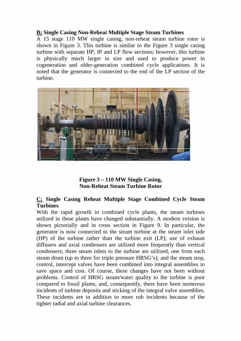
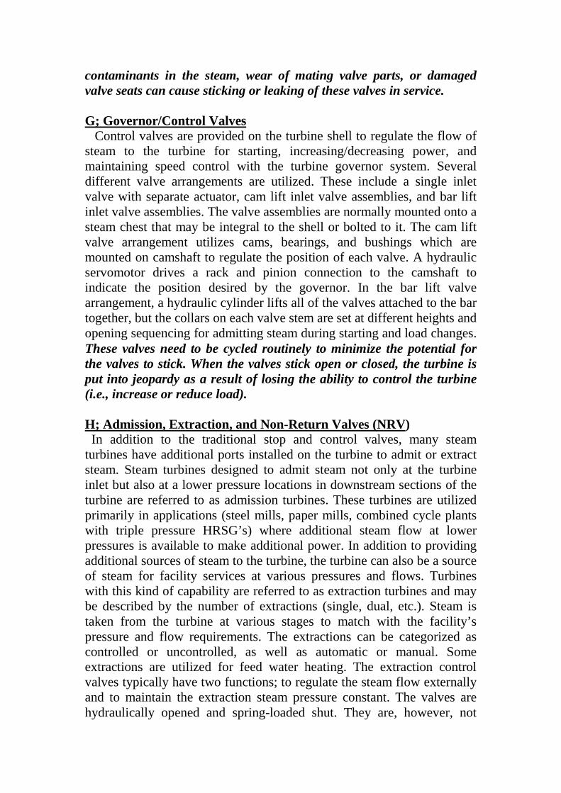
B; Single Casing Non-Reheat Multiple Stage Steam Turbines A 15 stage 110 MW single casing, non-reheat steam turbine rotor is shown in Figure 3. This turbine is similar to the Figure 3 single casing turbine with separate HP, IP and LP flow sections; however, this turbine is physically much larger in size and used to produce power in cogeneration and older-generation combined cycle applications. It is noted that the generator is connected to the end of the LP section of the turbine.
Figure 3 – 110 MW Single Casing, Non-Reheat Steam Turbine Rotor
C; Single Casing Reheat Multiple Stage Combined Cycle Steam Turbines With the rapid growth in combined cycle plants, the steam turbines utilized in these plants have changed substantially. A modern version is shown pictorially and in cross section in Figure 9. In particular, the generator is now connected to the steam turbine at the steam inlet side (HP) of the turbine rather than the turbine exit (LP); use of exhaust diffusers and axial condensers are utilized more frequently than vertical condensers; three steam inlets to the turbine are utilized, one from each steam drum (up to three for triple pressure HRSG’s); and the steam stop, control, intercept valves have been combined into integral assemblies to save space and cost. Of course, these changes have not been without problems. Control of HRSG steam/water quality to the turbine is poor compared to fossil plants, and, consequently, there have been numerous incidents of turbine deposits and sticking of the integral valve assemblies. These incidents are in addition to more rub incidents because of the tighter radial and axial turbine clearances.
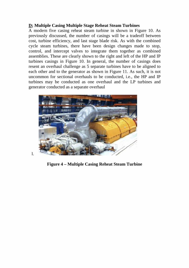
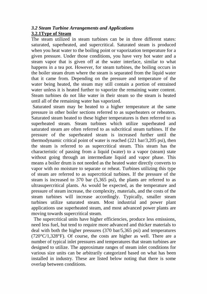
D; Multiple Casing Multiple Stage Reheat Steam Turbines A modern five casing reheat steam turbine in shown in Figure 10. As previously discussed, the number of casings will be a tradeoff between cost, turbine efficiency, and last stage blade risk. As with the combined cycle steam turbines, there have been design changes made to stop, control, and intercept valves to integrate them together as combined assemblies. These are clearly shown to the right and left of the HP and IP turbines casings in Figure 10. In general, the number of casings does resent an overhaul challenge as 5 separate turbines have to be aligned to each other and to the generator as shown in Figure 11. As such, it is not uncommon for sectional overhauls to be conducted, i.e., the HP and IP turbines may be conducted as one overhaul and the LP turbines and generator conducted as a separate overhaul
l.
Figure 4 – Multiple Casing Reheat Steam Turbine

Figure 5– Multiple Casing Reheat Steam Turbine 3.4 Monitoring, Operations, Maintenance, and Training Infrastructure Training Infrastructure Regardless of the size, number of casings, steam conditions, and arrangements, it is essential that steam turbines have effective monitoring, operating and maintenance procedures/practices, and training for personnel. These topics are discussed in the next sections. Monitoring Equipment Monitoring To effectively manage the health and performance of steam turbines, there are a number of turbine parameters which should be measured, monitored and/or displayed on a continuous basis. How much information is monitored is a function of the steam turbine design and application, but with today’s modern steam turbines, the following parameters should be monitored: • Speed (RPM) and load (kW/MW, or shaft horsepower (SHP)) • Steam turbine inlet pressure and temperature • Steam turbine 1st stage pressure and temperature (these are the conditions downstream of the first/large impulse stage before remaining HP section blading, as applicable)

• HP turbine outlet (or cold reheat), IP turbine inlet (or hot reheat), and IP turbine outlet/LP turbine inlet (or crossover) pressures and temperatures for reheat and multiple shell turbines only • Steam turbine rotor/shell differential expansions (as applicable for large turbines) • Steam turbine shell and steam chest temperatures/differentials (lower and upper half thermocouples installed in HP and IP turbine sections for large turbines) • Admission and extraction pressures and temperatures (as applicable) • Extraction line thermocouples to detect water induction (as applicable) • Water and steam purity at the main steam inlet and condensate pump discharge • Sealing steam and exhauster pressures (as applicable) • Steam turbine exhausts pressure and temperature • Lube oil and hydraulic fluid supply pressures and temperatures • Cooling water supply pressures and temperatures for the lube oil and hydraulic fluid systems • Journal bearing and thrust bearing metal temperatures (or drain temperatures, if applicable) for the turbine and gearbox (as applicable) • Bearing vibration – seismic, shaft rider or shaft x-and-y proximity probes measurements for all turbine and gearbox (pinion) bearing locations (as applicable) Monitoring of these and other parameters is typically done in conjunction with today’s modern turbine digital controls and plant control room systems. These systems will also handle the starting sequence, synchronizing, loading, speed governing, alarms, and trip logic for the turbine, gearbox (if present), generator, and any supporting systems. These systems also provide the electronic portion of the protection (i.e., turbine over speed) for critical turbine and generator parameters. For older units there may be an analog control system which provides limited protection along with mechanical/electrical devices on the unit. There usually is a limited display of monitoring parameters. For even older units, all operation will be manual with only a gage panel to monitor a few turbine parameters. Vibration monitoring is done periodically using hand-held instrumentation. These older units are dependent solely on the knowledge of the operating staff, the presence and use of written operating procedures, and the mechanical/electrical devices on the unit for protection. All of these issues are important for every unit but the consequence is higher with older, outdated units

summary
In Table 2, the main wear out problems with steam turbines is summarized, together with an outline of how condition monitoring can detect them.
Part affected Wear out problem Comments, suitable condition
monitoring
Blades
Erosion by solid particles(also erosion by water droplets on latter LP blades)
Usually occurs gradually, worst at inlet blades. Less usual on sets with drum boilers and/or sub-critical inlet steam conditions, or with bypass systems. Performance analysis detects.
Blades Parts breaking off Usually sudden. Vibration analysis and Performance analysis detects.
Bearings Scoring damage to white metal
Performance analysis, vibration analysis, wears particles in oil (but representative sampling at each bearing is rare).
Rotors Rubbing, temporary unbalance, cracking, misalignment
Vibration analysis, and off-line, some NDT (not detailed in this paper)
Valve spindles
Shaft and inter-stage glands (seals)
Casing joints
LP manhole gaskets
Internal steam piping and fittings
Leakage due to wear, distortion, breakage
Likely to occur gradually, but can be sudden. Performance analysis detects.
Effect of seal wear is relatively greater for HP blades. For impulse machines, the relative lost output for each 25µm increase above design clearance of about 600µm is:
• HP: blade tips, 5kW; inter-stage seals, 6kW per stage; end glands 15 to 25kW.
• IP: blade tips, 2.5kW; inter-stage 2kW per stage; end glands 5kW
• LP: Blades tips and inter stage, 1.5kW per stage; end glands 2kW.

For reaction blades, the effect will be greater.
Steam valve strainers
Valve spindles
Blading
Deposits (more prevalent with base loaded sets as cyclic loading tends to have a blade washing effect).
Likely to occur gradually, mostly in areas around 260°C. Some on-load blade washing occurs with forced steam cooling. Performance analysis detects. Blade surface roughness has biggest effect at higher steam pressures. One case gave 17% drop in output from deposits varying between 250 to 2300 µm in thickness.
Permissible roughness for LP blades can be 100× coarser than for HP blades. One test with surface finish equivalent to 500 grit emery paper caused 5% to 7% less efficiency in HP blades, about 2% in LP.
Generator rotor, stator Insulation faults Electrical plant testing (several
techniques
Condenser Air in leakage Tube fouling Performance analysis
Feed water heaters
Air in leakage, tube fouling by scale or oil
Performance analysis
Valves - HP, IP bypass, etc
Leakage Performance analysis. Acoustic leakage detection is also possible.
OPERATIONS AND MAINTENANCE PERFORMANCE of Gas Turbine OPERATION (a) Starting. Starting sequence of any gas turbine from rest to its rated speed requires a certain

order of events to be accomplished either manually or automatically. The major steps in sequence are cranking, ignition, acceleration and governing. The following is typical starting sequence of a gas turbine 1. Application of control power illuminates all the malfunctions lights. 2. Operate ‘Reset switch’ to reset malfunctions circuits: By doing so, malfunction lights go off and all control devices assume the condition for starting. 3. Operate “Start” switch to initiate starting sequence. By doing this, lube oil pump and cooling fan start. If there are separate switch for these, operate these. 4. When lube oil reaches a preset pressure, the starter is energized and cranking of the engine begins. 5. With the cranking of starting of starter, the engine and exhausts ducts are purged of any combustible gases that might be present. 6. During the cranking cycle, the fuel boost pump is used and operated to increase fuel pressure. 7. As soon as the fuel pressure has reached a prescribed minimum value, fuel and ignition switches are turned on provided a preset turbine speed has been reached. 8. The turbine accelerates due to combustion of fuel and assistance of cranking motor. At a preset value, say in the order of 70% of rated speed, the starter and ignition are cut-off automatically. 9. The turbine becomes self- sustaining and accelerates on its own to its governed speed till the governing system takes over the control. (b) Shut down. To stop the gas turbine fuel supply should be turned off. This is accomplished by closing the fuel valve either manually or by de-energizing an electrically operated valve. In cases where sleeve bearings are used, circulation of lube oil to bearings after shutdown is necessary for cooling. MAINTENANCE PERFORMANCE The type of maintenance, which is done on the gas turbine, is the same as that of steam turbines. From the experiences of the most manufactures of gas turbine equipment forced outages are frequently caused-at least in part by inadequate maintenance. The basic purposes of a preventive maintenance programme are to reduce forced outages.

The following are the principal sub-systems of the gas turbine for which manufacturers present maintenance instructions: 1. Turbine gear 2. Starting 3. Clutches and coupling 4. Fuel system 5. Pneumatic system 6. Fire protection system 7. Control equipment 8. Generator-exciter 9. Electrical controls 10. Auxiliary gear and main gear 11. Gas turbine 12. Lube oil system 13. Over speed protection 14. Temperature control and monitoring systems 15. Air conditioning system 16. Emergency power 17. Motors 18. Related station equipment. Maintenance is carried out daily monthly, quarterly, semi-annually and annually. So for the sequence of overhaul is concerned, it is similar to that of steam turbines with some exceptions. TROUBLESHOOTING AND REMEDIES Modern gas turbines are usually equipped with a very sophisticated protection system using microprocessor and computers, which gives a visual and audio alarm when any pre-established safe condition is violated. In all types of alarm, it is not necessary to shut the gas turbine down. If an alarm condition is of sufficient duration and magnitude the unit will trip and shut down automatically. The following are the principal symptoms of gas turbine malfunctions and the most common causes of these malfunctions: (a) Drop in compressor discharge pressure and subsequent drop in load: 1. Dirty intake screens 2. Dirty compressor blades 3. Loss of compressor blades 4. Damaged labyrinth seals (b) Smoke or dark stack: 1. Burner nozzle-dirty or worn Puffs of smoke indicate that carbon is building up around the fuel nozzle and then passing through the turbine creating rapid wear of blades, vanes and shrouds. 2. Uneven distribution of fuel to combustion chambers. 3. Combustion chambers damaged or out of position. (c) Spread in turbine discharge temperatures: 1. Bad thermocouples 2. Uneven fuel to burners or dirty nozzles
3. Combustion chambers damaged or out of position 4. Unlit burners 5. Damaged burner nozzles (d) High wheel space temperatures: 1. Cooling airlines plugged 2. Cooling air heat exchanger dirty, leaking water or loss of cooling water. 3. Bad thermocouples 4. Wheel space seals worn due to rubs by axial movement or rotor (worn thrust bearing), bowed shaft or casing out of round to open seal clearances 5. Cooling air supply not functioning properly. (e) High turbine exhaust temperatures: 1. Loss of turbine blades or damaged inlet vanes 2. Bad thermocouples 3. Exhaust temperature controller out of adjustment 4. Increased blade tip clearances due to radial ribs. 5. Dirty air compressor. (f ) High Turbine Exhaust Pressure: 1.Turning vanes in turbine discharge duct damaged or missing. 2. Discharge silencer damaged. (g) Vibration: 1. Indicating instrument out of adjustment 2. Loose shaft couplings 3. Bowed turbine shaft 4. Broken or missing turbine blades 5. Damaged bearings 6. Shaft mis-alignment (h) Loss of fuel pressure: 1. Fuel control valve out of adjustment 2. Fuel strainers dirty 3. Fuel pump or compressor damaged (i) Light of failure: 1. Faulty spark plug 2. Combustion chamber cross fire tubes out of place. 3. Electrical control out of adjustment 4. Fuel proportion out of adjustment 5. Fuel atomizing air out of proportion 6. Burner nozzles dirty or worn 7. Combustion chamber damaged (j) Machine ‘Hunting’: 1. Worn governor and control parts 2. Fluctuating fuel controllers 3. Fluctuating exhaust temperature controllers 4. Hydraulic control valves leaking or strainers dirty. (k) Loss of oil pressure 1. Filters 2. Pump failure 3. Leakage in pump.