towards high throughput plasma based water purifiers
TRANSCRIPT

Journal of Physics D: Applied Physics
TOPICAL REVIEW
To cite this article: John E Foster et al 2018 J. Phys. D: Appl. Phys. 51 293001
View the article online for updates and enhancements.
Related contentPlasma–liquid interactions: a review androadmapP J Bruggeman, M J Kushner, B R Lockeet al.
-
Towards understanding plasma formationin liquid water via single bubble studiesJohn E. Foster, Bradley Sommers andSarah Gucker
-
Plasmas for environmental issues: fromhydrogen production to 2D materialsassemblyE Tatarova, N Bundaleska, J Ph Sarretteet al.
-
Recent citationsHybrid electric discharge plasmatechnologies for water decontamination: ashort reviewKefeng SHANG et al
-
Special issue on environmentalapplications of thermal and non-thermalplasmasAkira Mizuno and Selma MededovicThagard
-
The penetration and concentration ofsolvated electrons and hydroxyl radicals ata plasma-liquid interfacePaul Rumbach et al
-
This content was downloaded from IP address 141.213.172.164 on 21/04/2019 at 02:48

1 © 2018 IOP Publishing Ltd Printed in the UK
Journal of Physics D: Applied Physics
1. Scope
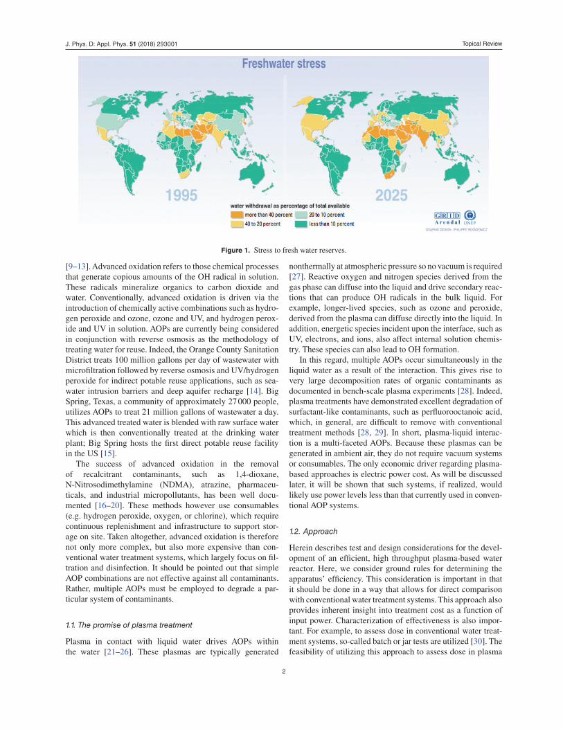
The confluence of societally impacting forces such as climate change, overpopulation, and overdevelopment are stress-ing freshwater reserves (see figure 1) [1, 2]. Beyond issues of scarcity, fresh water quality is increasingly affected by pollution derived from agriculture and industry. Water reuse addresses water scarcity [3–6]. By water reuse, we refer to the use of technology to directly or indirectly recycle treated
wastewater effluent for potable and non-potable applications, thereby augmenting existing water supplies. In the US alone, water reuse, if implemented, could meet up to 30% of the cur-rent public water supply demand [7]. Advanced water treat-ment technologies are required to reduce contaminant levels in reused water to acceptable values [8]. These same technolo-gies have the potential to also remove those contaminants not addressed by conventional water treatment systems. Advanced oxidation processes (AOPs) have been identified as the basis for the treatment of difficult water, addressing contaminants that are difficult to strip, absorb or biodegrade conventionally
Towards high throughput plasma based
water purifiers: design considerations and
the pathway towards practical application
John E Foster1,3 , Selman Mujovic1, Joseph Groele1
and Isaiah M Blankson2
1 Department of Nuclear Engineering and Radiological Sciences, University of Michigan, Ann Arbor, MI, United States of America2 NASA Glenn Research Center, Cleveland, OH, United States of America
E-mail: [email protected]
Received 2 February 2018, revised 11 May 2018Accepted for publication 25 May 2018Published 22 June 2018
Abstract
Plasma-based water purification methods offer an alternative means to introduce advanced oxidation into liquid water. This approach drives a number of advanced oxidation processes simultaneously without the need for conventional consumables, making this approach potentially not only energy efficient but also cost effective. The chief barrier to implementing plasma-based methods for water purification is scale-up. This paper describes the scale-up problem, the current state of the art, and design considerations both from plasma science and engineering standpoints. The overall objective of this paper is to summarize key challenges to scale-up and implementation as well as elaborate on approaches to achieving a high throughput plasma-based water treatment system. Plasma dose delivery requirements for a given contaminant are estimated using basic rate equations. Two scale-up design approaches are also discussed along with performance data. The pathway from bench-top demonstration of plasma-based systems to piloting and ultimately reduction of the technology to practice are also elaborated upon.
Keywords: plasma, water, advanced oxidation, contaminants of emerging concern, water treatment, reactor
(Some figures may appear in colour only in the online journal)
Topical Review
3 Author to whom any correspondence should be addressed.
1361-6463/18/293001+18$33.00
https://doi.org/10.1088/1361-6463/aac816J. Phys. D: Appl. Phys. 51 (2018) 293001 (18pp)
Topical Review
2
[9–13]. Advanced oxidation refers to those chemical processes that generate copious amounts of the OH radical in solution. These radicals mineralize organics to carbon dioxide and water. Conventionally, advanced oxidation is driven via the introduction of chemically active combinations such as hydro-gen peroxide and ozone, ozone and UV, and hydrogen perox-ide and UV in solution. AOPs are currently being considered in conjunction with reverse osmosis as the methodology of treating water for reuse. Indeed, the Orange County Sanitation District treats 100 million gallons per day of wastewater with microfiltration followed by reverse osmosis and UV/hydrogen peroxide for indirect potable reuse applications, such as sea-water intrusion barriers and deep aquifer recharge [14]. Big Spring, Texas, a community of approximately 27 000 people, utilizes AOPs to treat 21 million gallons of wastewater a day. This advanced treated water is blended with raw surface water which is then conventionally treated at the drinking water plant; Big Spring hosts the first direct potable reuse facility in the US [15].
The success of advanced oxidation in the removal of recalcitrant contaminants, such as 1,4-dioxane, N-Nitrosodimethylamine (NDMA), atrazine, pharmaceu-ticals, and industrial micropollutants, has been well docu-mented [16–20]. These methods however use consumables (e.g. hydrogen peroxide, oxygen, or chlorine), which require continuous replenishment and infrastructure to support stor-age on site. Taken altogether, advanced oxidation is therefore not only more complex, but also more expensive than con-ventional water treatment systems, which largely focus on fil-tration and disinfection. It should be pointed out that simple AOP combinations are not effective against all contaminants. Rather, multiple AOPs must be employed to degrade a par-ticular system of contaminants.
1.1. The promise of plasma treatment
Plasma in contact with liquid water drives AOPs within the water [21–26]. These plasmas are typically generated
nonthermally at atmospheric pressure so no vacuum is required [27]. Reactive oxygen and nitrogen species derived from the gas phase can diffuse into the liquid and drive secondary reac-tions that can produce OH radicals in the bulk liquid. For example, longer-lived species, such as ozone and peroxide, derived from the plasma can diffuse directly into the liquid. In addition, energetic species incident upon the interface, such as UV, electrons, and ions, also affect internal solution chemis-try. These species can also lead to OH formation.
In this regard, multiple AOPs occur simultaneously in the liquid water as a result of the interaction. This gives rise to very large decomposition rates of organic contaminants as documented in bench-scale plasma experiments [28]. Indeed, plasma treatments have demonstrated excellent degradation of surfactant-like contaminants, such as perfluorooctanoic acid, which, in general, are difficult to remove with conventional treatment methods [28, 29]. In short, plasma-liquid interac-tion is a multi-faceted AOPs. Because these plasmas can be generated in ambient air, they do not require vacuum systems or consumables. The only economic driver regarding plasma-based approaches is electric power cost. As will be discussed later, it will be shown that such systems, if realized, would likely use power levels less than that currently used in conven-tional AOP systems.
1.2. Approach
Herein describes test and design considerations for the devel-opment of an efficient, high throughput plasma-based water reactor. Here, we consider ground rules for determining the apparatus’ efficiency. This consideration is important in that it should be done in a way that allows for direct comparison with conventional water treatment systems. This approach also provides inherent insight into treatment cost as a function of input power. Characterization of effectiveness is also impor-tant. For example, to assess dose in conventional water treat-ment systems, so-called batch or jar tests are utilized [30]. The feasibility of utilizing this approach to assess dose in plasma
Figure 1. Stress to fresh water reserves.
J. Phys. D: Appl. Phys. 51 (2018) 293001

Topical Review
3
reactors will be discussed as well. The importance of opti-mizing both contact time and contact area is then discussed from the context of the plasma-liquid interface. Ultimately, the key to optimizing plasma-based water purification systems lies in understanding the source chemistry taking place in the gas phase, at the plasma-liquid interface, and subsequent mass transport processes into the bulk solution that follow. A brief review of attempts to scale-up plasma technology for water treatment and a description of piloting results of a prototype system are presented. We finally discuss two example sources that have the capacity for high throughput applications cur-rently under development at NASA and the University of Michigan.
1.3. Metrics
The chief measure of the effectiveness of any water purifi-cation method lies in its ability to degrade contaminants to concentrations below the mandated maximum contaminant level. Often the evolution of a contaminant in solution under radical attack (e.g. OH) can be complex, leading to the con-version of the contaminant itself into intermediates that can consume OH. Indeed, the chain reaction of OH with these resulting remnants of the original contaminant is desired as it ultimately leads to mineralization. The rate law for such reac-tions can be determined experimentally. A general overall rate law capturing these physical processes has been suggested for steady state and completely mixed solution:
dCdt
=−ξPkc [C] /V
kc [C] +∑
i ki [Si] (1)
where Si is the scavenger molar concentrations at steady state, ki are the second-order scavenger-OH rate constants, C is the contaminant molar concentration, kc is the contaminant-OH rate constant, P is the power, V is the volume, and ξ is the system dependent constant [31]. ξ is related to the conversion of input power to reactive species that actually participate in decomposition of contaminants. For instance, in photochemi-cal reactors, ξ is a function of the applied power, the power of useful photons emitted, the fraction of photons absorbed by the solution, and quantum yield for radical production. Here, scavengers are defined as any OH-consuming compound. If the contaminant concentration is high, the decomposition rate exhibits zeroth-order decay. If the scavenger concentration is high, the rate equation is first-order. In that case, the pseudo first-order coefficient:
k′ =ξPkc
V∑i ki [Si]
. (2)
Since electrical power is required for operation, the effective-ness and efficiency of plasma-based water systems involve quantifying contaminate concentration change and the elec-trical energy expended. For example, Malik reviewed a range of plasma reactor embodiments, which were assigned an energy yield for the decomposition of dyes in solution known as the G50 [32]. The G50 yield represents the energy required to yield a 50% conversion of a given pollutant:
G50 = 1.8 × 10⁻⁶CoVoM/ (P · t50), where Co is the initial molar concentration, Vo is the initial volume, M is the molecu-lar mass of the pollutant, P is the reactor operating power, and t50 is the time for 50% reduction in concentration of the pollutant. Here, the units of this metric are g kWh−1. This expression is appropriate for batch reactors and assumes zeroth-order contaminant decay. This expression does not capture efficiency or energy requirements for flow through systems. Additionally, the metric does not consider evapora-tion or give any direct insight into the kinetics of the reaction.
As illustrated in Malik’s work, G50 is a useful parameter to compare past fixed-volume plasma reactor data; however, the unit itself is not standard. Instead, in the advanced oxi-dation water treatment community, the electric energy per
mass (EEM) and the electric energy per order (EEO) have been
developed [33]. EEM = 1000P·tV·(ci−cf )
for closed loop reactors and EEM = P
F·(ci−cf ) for flow through reactors where ci is the initial
mass concentration, cf is the final mass concentration, and F is the flow rate. EEM is appropriate for zeroth-order decomposi-tion and notice, the batch EEM is the inverse of G50. On the other hand, EEO is defined as the electrical energy required to reduce the contaminant concentration in a fixed volume of solution (e.g. 1000 l) one order of magnitude (90%). It is defined as:
EEO = P·tV·log
(cicf
) for batch processes andEEO = PF·log
(cicf
)
for flow through reactors. This parameter is independent of concentration if the contaminant exhibits first-order removal.
Note that for flow through reactors, the log(
cicf
) factor is actu-
ally the effective first-order rate coefficient multiplied by log e and the detention time. Nonetheless, it has been shown that the energy efficiency for the removal of a given contaminant can vary widely depending on the initial concentration, initial pH, and volume of contaminated solution [34]. Thus, it should be kept in mind that these parameters focus on the efficiency to remove a specific compound.
1.4. Dose considerations
While electrical efficiency is a key consideration, the dose required to achieve the desired treatment is equally impor-tant. Assessing dose in plasma reactors is somewhat difficult in that contributions to decomposition are derived from many reaction pathways, including UV-driven processes. Much emphasis in plasma studies focuses on the formation of reac-tive species, such as OH, O3, H2O2, NO, NO−
3 , and OONO− [35]. While these processes are important, UV light may also play a key role in the contaminant decomposition because it can directly photolyze contaminants, such as NDMA, and produce ROS similar to conventional UV-based AOPs [36]. More research is required to assess plasma-driven UV pho-tochemistry as it is known that significant percentage of dis-charge power goes into UV production. The actual amount of UV production varies with discharge type [27]. In the case of a UV-based AOP, the dose is related to the number of photons deposited. The number of photons produced can be calculated if the integrated emission is measured. Here, the
J. Phys. D: Appl. Phys. 51 (2018) 293001

Topical Review
4
number of photons of frequency ν generated in moles per liter
is: Q = PηNAVhν where P is the power deposited into the UV
lamp, η is the photon conversion efficiency, and h is Planck’s constant. While straightforward to access with conventional lamps, Q is difficult to assess in a plasma reactor as it requires a reliable method to assess η. Indeed, tracking the multitude of processes in a plasma reactor is part of the issue in assess-ing dose.
In conventional advanced oxidation systems, the dose required to degrade a given contaminant to the desired level is carried out using a bench scale test [37]. Conventionally, an oxidant such as ozone is applied to water samples spiked with known concentrations of target contaminants. The con-centration of the oxidants, contaminants, and scavengers in solution are measured as a function of time. The pseudo-first order rate constant for the oxidant can be determined by fitting the data. Similarly, the effective rate constant for the contami-nants can also be determined provided that the rate law, the oxidant decay rate constant, and the production rate of OH by the oxidant are known. This rate constant can also be deter-mined by best fit method. In this manner the required dose as well as detention time can be determined. By detention time, we refer to the time the water to be treated spends or resides in the reactor; thus in this context, this parameter represents the contact time between contaminants and radicals. This basic approach can also be applied to plasma reactors as well, since currently the dose delivered by the plasma to the liquid is not well understood. In this case, one can directly measure hydro-gen peroxide and ozone production in addition to UV fluence as a function of time, along with assessing the concentration of the contaminant as a function of time. This would allow for the determination of the rate constants in an analogous manner with conventional advanced oxidation. This approach provides insight not only into the kinetics but also provides a basis for comparison with conventional advanced oxida-tion methods. Here the assumption is that plasma is simply an alternative method for delivering AOPs where instead of the use of consumables, it is the plasma-liquid interaction that produces the ozone, UV, and peroxide.
To summarize, currently, plasma reactor research studies utilizes non-standard units to assess efficiency. Advanced oxi-dation methods have advanced to practice in the water treat-ment arena. The efficiency of AOP systems is conventionally assessed using EEO, it is recommended that plasma reactor studies assess performance using this metric as well.
1.5. Scale up: general considerations
An important consideration for the scale up of plasma reac-tors from laboratory demonstrations to industrial applica-tions is maximizing plasma contact with the liquid. With this consideration satisfied, it is then possible to develop actual rules or scaling laws that dictate how to optimize parameters such as discharge characteristics, electrode dimensions, and gas and liquid flow rates [38]. Malik sur-veyed a range of plasma reactor approaches in an attempt to assess which implementation approach was most efficient
[8]. An outcome of the Malik plasma reactor survey was that those reactor configurations that exposed thin layers of water or small droplets of water to plasma were the most efficient. These geometries maximize the plasma- induced dose in the liquid. It is argued that in these cases the surface area to volume ratio presented to the plasma is larger. In general, reactive species diffusion time in liquid water is slow [39]. Indeed, ROS propagation times as inferred via 2D plasma bubble studies suggest diffusion front speeds of order 0.1 mm s−1. It should be pointed out that if stream-ers contact the surface directly, transport times can increase dramatically (>10 times). Therefore, the thinner the water layer, the more complete the treatment as the liquid passes through the active plasma treatment zone. While the Malik study points one in the direction of which geometries make the most efficient plasma reactors for water treatment, based on his assessment, the most efficient geometries are also inherently low throughput—with the general focus on thin water layers or small droplets. More recently, Stratton et al developed general guidelines for plasma reactor design and optimization for water treatment. This study highlighted the importance of maximizing the plasma-liquid contact area and radical transport across the interface [40].
The most well-known early attempt to commercialize a plasma reactor for water treatment was the effort carried out by the company AquaPure [41]. The AquaPure reactor design was faithful to considerations consistent with the Malik study; that is, thin layers of water are subjected to nonthermal, atmos-pheric pressure plasma, as depicted in figure 2. The AquaPure system utilized a brush array of plasma applicators (carbon electrodes) positioned over a flowing, thin sheet of water. While the decomposition efficiency of this reactor exceeded conventional AOPs for the reduction of Trichloroethylene (TCE) and NDMA, the throughput was rather low rang-ing from approximately 10–15 l min−1 (3–4 gallons min−1). Treatment levels of interest for practical application (e.g. point of use residential) start at around 20 l min−1, based on average household usage. Higher flow rates can be generally applied to industrial water treatment applications. Starting at around 500 l min−1, reactors can be considered for small townships or municipalities.
In general, while numerous plasma reactors have dem-onstrated the ability to decompose a range of contaminants, the majority of these studies processed water in small batch reactor configurations. In general, once-through configura-tions are desired for practical applications particularly where throughput is fairly high.
Figure 2. Aquapure plasma applicator geometry.
J. Phys. D: Appl. Phys. 51 (2018) 293001

Topical Review
5
1.6. The problem of the plasma liquid interface, general considerations
The key driver of plasma-induced reactivity in liquid water is the plasma-liquid interface. The contact area between the plasma and the water ultimately determines the treatable throughput; thus, understanding the physics and chemistry of the plasma-liquid interface (depicted in figure 3(a)) is key to optimizing plasma water reactors (PWR). The plasma-liquid interface is the thin, reactive interfacial zone formed between the gas phase plasma and the liquid water. The reactive zone is not a distinct boundary in that it includes the supersaturated vapor layer above the liquid as well as a thin layer within the liquid where the chemistry can be driven far from equilib-rium. Here, species produced in the gas phase can diffuse into solution. These species include reactive oxygen and nitrogen species, such as hydroxyl, hydrogen peroxide, superoxide and NOx. Incident UV can also drive the production of OH in solution via the detachment of OH−: OH−UV→ e− + OH [42]. Recombination of OH in solution produces hydrogen perox-ide. The incident electrons solvate only to ultimately decom-pose water molecules on a microsecond time scale to produce OH−. The longer-lived species, such as hydrogen peroxide and ozone, can diffuse deeper into solution, ultimately form-ing OH, which in turn can attack contaminants within the bulk.
Understanding the effectiveness of a reactor requires in turn an understanding of the mass transfer rates of the various reac-tive species produced at the interface. This knowledge allows
one to access interfacial contact time and associated power required to deliver the dose. The longer-lived species are pri-marily transported via four interrelated physical processes. These processes include multi-layer diffusion, electrostatic effects, plasma-induced fluid flow, and self-organization. One can crudely divide the plasma contact interfacial region into a number of zones as depicted in figure 3(a), each of which play a key role in transport. Optimizing oxidant transfer from these various regions is key to ensuring the delivery of appropriate dose to the liquid. As can be seen in the figure, beyond the plasma glow, a sheath forms at the interface. This sheath regu-lates the flow of charged species in and out of the solution. The sheath can also impart activation energy to charged spe-cies for chemical reactions in solution. Just beyond the sheath, located essentially at the interface, is an electric field in solu-tion known as a double layer. Here, in finite conductivity solutions, a voltage drop develops in solution. The associated electric field regulates ion transport in the vicinity of the inter-face. This field has been shown to affect local rate constants [43]. Since the double layer field affects ion flow, it also strati-fies chemistry in the interfacial region and can give rise to a pH gradient [44]. Interestingly, the spatial extent of this region depends on water quality parameters such as conductivity. It has been shown that the spatial extent of the double layer can greatly exceed the classical Debye Hückel length scale. Indeed, at high electrolyte concentrations, the length scale can exceed 100 times the classical value [45]. In this regard, the double layer thickness and associated chemistry such as dose delivery is water quality dependent. The sign of the net charge delivered to the interface also affects water chemis-try. Net positive irradiation tends to acidify solution while net electron flux gives rise to solvated electrons that tends to pro-duce more basic solutions [46]. pH stratification and charge injection affects water quality in at least two important ways. Particulates in solution clump when surface charge is neutral-ized. Particle surface charge in solution is pH dependent. In solution, plasma-driven chemical reactions can also lead to precipitation. Plasma dose can therefore aid in particulate coagulation. Figure 3(b) illustrates an in-house demonstration of plasma-induced precipitation. pH also affects the concen-tration of HCO−
3 and CO2−3 , which are OH radical scavengers.
Charge injection can also affect the oxidation state of metal ions in solution. Reduced metal ions such as Fe(II) or Mn(II) are also OH scavengers.
Fluid effects derived at the plasma-liquid interface are also important. A range of plasma-induced fluid dynamic effects have been reported to date [47–51]. These include plasma-induced circulation, capillary wave formation, and turbulent diffusion. These effects can enhance not only the interfacial transport but also mixing since the circulation effects extend well beyond the interface. The presence of physical electrodes in the fluid flow field can also enhance mixing through the for-mation of mixing eddies. The nature and rate of radical trans-port in the liquid is dependent on the nature of the discharge. Diffusive plasma attachments at the interface tend to give rise to transport best characterized as simple diffusion, essentially a slow process. On the other hand, streamer-type microdis-charges induce rapid transport of species into the solution due
Figure 3. (a) Physical processes prevailing at plasma liquid interface. (b) Plasma driven precipitation.
J. Phys. D: Appl. Phys. 51 (2018) 293001

Topical Review
6
to Marangoni flows driven by heat and concentration gradi-ents at the interface (see figure 4) [35, 52]. The contrasting effects of the two discharge types show the true difficulty in scaling up. If one is able to generate a diffuse attachment at the interface, the radical injection rate is slow but the surface contact area is modest. With the streamer, surface attach-ment is highly localized but induced flows can be large scale. Ideally, a combination of diffuse and streamer discharges may be best since the species produced by the diffuse attachment can be swept into the bulk by the large scale flows generated by the streamer attachment [53]. In any event, plasma-induced flows cannot be overlooked as the effect in fact provides an opportunity to optimize dose delivery.
Related to plasma-induced circulation is plasma self-organ-ization. It is well known that in DC glows with liquid elec-trodes under certain conditions the plasma attachment at the liquid surface will self-organize into intricate, very localized patterns. The resulting self-organization gives rise to circula-tion both on the surface and in the volume. Additionally, the self-organization means that not only is the plasma attachment non-uniform, but the plasma attachment is also in motion. In this regard, the delivered dose is spatially and time dependent. Implications regarding these physical processes on delivered dose remain not well understood.
2. Plasma water purification: scale up
Plasma-based water purification utilizes plasma to generate AOPs in liquid water using air or water itself as the active medium. Advanced oxidation is an effective method of treat-ing recalcitrant contaminants and contaminants of emerging concern in particular [54]. An impediment to the eventual adaptation of plasma-based AOP water treatment technolo-gies is scale-up. Plasma-based water purification approaches have been researched for some time now with their earliest embodiment appearing in patent applications as early as the early 20th century [55–57]! The chief scale up issue regard-ing atmospheric pressure plasma technology is that the dis-charges tend to be filamentary in form. This is largely due to the reduced electron diffusion lengths, typically micrometers,
at one atmosphere. In this regard, the application of high volt-age at atmospheric pressure produces discharges that are very localized and reminiscent of lightning. This very localized nature makes it difficult to integrate into large flow rate geom-etries. In the lab, contaminated water volumes of order a liter have been treated, but as mentioned earlier, treatment flows of order 10 s of l min−1 are required in practice.
2.1. Determining OH production in practical settings
A key aspect of plasma-based water purification is the pro-duction of the OH radical, which rapidly degrades organic contaminants. The OH rate constant for a range of organic contaminants encountered in drinking and wastewater have been tabulated for room temperature reactions. The OH reac-tion with organic contaminant, CR, can be described by the second-order rate equation:
dCR
dt= −kR · COH · CR, (3)
where COH and CR are the concentrations of OH and the con-taminant R, respectively.
Of particular interest is the removal from drinking water contaminants of emerging concern. 1,4-dioxane is a con-taminant of particular concern for water reuse as not only is it known to be a likely carcinogen but it can also cause liver and kidney damage. Figure 5 illustrates superfund sites where the groundwater has been contaminated with this toxin [58]. In support of water reuse applications, it is desirable to remove such contaminants to minimize health impacts. While the EPA has not established a maximum contamination level for 1,4-dioxane, the WHO has established 50 μg l−1 as the guideline value for remediation action [59]. Removal of 1,4-dioxane, while difficult and expensive, can be achieved using advanced oxidation [60]. Typically, pump and treat is implemented to clean contaminated groundwater plumes [61]. Here, the groundwater is pumped out of a given ground water site and treated with an AOPs such as hydrogen peroxide-UV to remove the contaminant before its returned to the environ-ment, usually via a matriculation lagoon. Plasma-based approaches have the potential to remove contaminants from
Figure 4. Plasma induced Marangoni flow.Figure 5. 1,4-dioxane superfund survey problem in the US.
J. Phys. D: Appl. Phys. 51 (2018) 293001

Topical Review
7
pumped out groundwater as well; however, for the approach to be practical, the OH production rate must be sufficiently high so that contact times can be reduced to accommodate large flow rates (typically ~ one million gallons/day) [62].
For illustration purposes, 1,4 dioxane was used as a test case to assess what concentrations of plasma generated OH would be necessary to reduce the contaminant to acceptable levels as defined by the WHO or more recently the California ‘removal from service’ level of 35 μg l−1 [63]. California EPA notification level is 1 μg l−1. Using the second-order rate equation, the degradation of 1,4-dioxane was calculated as function of OH concentration and time for a starting con-centration of 1,4-dioxane of 9 μg l−1, a value observed at Superfund sites [53]. The exponential decay of 1,4-dioxane is obvious in figure 6; maintaining a high concentration of OH in solution clearly leads to more rapid decay. Since primar-ily OH destroys 1,4-dioxane, it is critical to approximate OH concentration in order to predict 1,4-dioxane kinetics. Though plasma provides plentiful pathways to OH production, it is possible to estimate the OH concentration of reactors by measuring 1,4-dioxane decay.
A key consideration is the rate at which the OH is actually produced. In conventional advanced oxidation, OH is gener-ated using consumables in tandem such as ozone and hydro-gen peroxide: H2O2 + 2O3 → 2OH + 3O2. Peroxide and UV are also effective in producing large amounts of OH. Analysis of underwater plasma jet data suggests that both ozone and hydrogen peroxide are produced in large quantities in solution [64]. It is therefore of interest to analyze plasma-based water purification based on this AOP to assess 1,4-dioxane decom-position in solution. Again, this is not the only mech anism prevailing during the plasma-liquid water interaction but one can assess its overall relative contribution to OH production. In order to carry out this exercise, the measured, plasma-produced concentrations of ozone and peroxide are used to calculate the degradation of 1,4-dioxane. Implicit here is the assumption that the ratio of the hydrogen peroxide to ozone concentration
can be controlled to achieve the proper dosage, which depends on water quality, disinfection byproduct formation, and man-agement of residuals. In this manner, we capture at least one reaction pathway that ultimately supplies OH. Here, we do not a priori specify the OH concentration but rather we calculate it based on known precursor concentrations and then determine its action on the contaminant and its intermediates. Insight into 1,4-dioxane decay and hence the required OH produc-tion, will ultimately lead to the ability to approximate reactor-specific decomposition of other persistent organics. To make this calcul ation realistic in regards to water encountered in a real water treatment plant, we account of contributions of: (1) alkalinity, (2) pH, and (3) the presence of suspended and dis-solved organic material. By alkalinity, we refer to the calcium carbonate concentration in the liquid, which is taken to be a typical value of 400 mg l−1. Note carbonates can scavenge OH. The pH is taken to be 7.5 and the dissolved organic carbon is taken to by approximately 1 mg l−1. Overall, these affect OH reactivity and compete with the contaminant decomposition by acting as OH scavengers. The reactions, which ultimately lead to OH production, implemented in this model are listed below (note ‘∗’ denotes an unpaired electron) [65, 66]:
O3 + HO−2 → O−∗
3 + HO∗2 k = 2.8 × 10⁶ M−1 s−1 at 25 C
(4)
HO∗2 � O−∗
2 + H+ Ka = 1.6 × 10⁻⁵ at 25 C (5)
O−∗2 + O3 → O−∗
3 + O2 k = 1.6 × 10⁹ M−1 s−1 at 25 C (6)
O−∗3 + H+ → HO∗
3 k = 5.2 × 10¹⁰ M−1 s−1 at 25 C (7)
HO∗3 → O2 + OH∗ k = 1.1 × 10⁵ M−1 s−1 at 25 C, (8)
where Ka is the equilibrium constant. Using the rate equa-tions associated with this chain of reactions, one can deter-mine 1,4-dioxane degradation as a function of time given a specified dose of ozone and peroxide. In this case, it is assumed that the plasma-water interaction provides the oxi-dants, which are well mixed in the reactor. In this model, a notional flow rate of one million gallons per day is used, typical of a small municipality. Derived from demonstration plasma units in bench scale tests, the effective ozone input is taken to be 1 mg l−1 per second. The peroxide concentration is taken to be 1 ppm. This number is derived from demonstra-tion plasma units in bench scale tests [67]. The key challenge is to input this dose into the treatment flows via a scale up approach. It is assumed that the treatment passes through four plasma treatment cells to improve treatment performance. We assume a partial pressure of ozone at the plasma-water inter-face of PO3 = 0.07 atm, similar to dosing used in conven-tional ozonators as a rough estimate. It should be pointed out that in solution, plasma-produced ozone matches the amount applied in conventional AOPs, so this assumption is quite plausible. This pressure is used to determine concentration in the liquid via Henry’s law taking into account the mass transfer coefficient. The final equation for the OH production may be written as:
Figure 6. 1,4-dioxane decomposition for different molar concentrations of OH (model results).
J. Phys. D: Appl. Phys. 51 (2018) 293001

Topical Review
8
[OH] =KO3 · PO3
HO3
k1[HO−
2
]+ k2 [H2O2] + k3 · [HCO3] + k4 · [CR] + k5 · [NOM]
(9)
where kn refers to the aforementioned rate constants, KO3 is the mass transfer coefficient for ozone, and NOM is the con-centration of natural organic matter. The model can be used to predict the OH generation rates for a range of water conditions. Furthermore, the model can estimate the contribution of OH consumed by contaminant CR. The degradation of the contami-nant, 1,4-dioxane in this case, can be described by the relation:
[1, 4 dioxane] =[1, 4 dioxane initial](
1 + kdioxane · τn
)n . (10)
Here, we use n = 4 for the four plasma reactors in series required to process the water. kdioxane is the pseudo first-order rate constant and is equivalent to the product of the OH deg-radation rate constant and the steady state concentration of OH. The initial concentration of 1,4-dioxane is 95 ppb, which has been measured in contaminated groundwater sites. τ is the total detention time; that is, the time the contaminant is in contact with the well-mixed, ozone-peroxide solution.
2.2. Hydrogen peroxide ozone model results
The model results are shown in figure 7. As can be seen in the rightmost panel, the 1,4-dioxane concentration is decreases exponentially as expected with detention time. The detention time itself is determined as the ratio of the total reactor vol-ume and the flow rate, which in this case was equivalent to one million gallons per day. While, as expected, the longer the treatment the greater the reduction, it is not desirable to have too long of a treatment time as it requires larger deten-tion tank volume, as can be seen in the leftmost panel. The problem with large detention volumes is that in general, the total plasma-based dose delivered to the tank has to increase to maintain an effective radical concentration. This in turn usually translates into either more reactor cells in series or greater input power. The plasma reactor must maintain the appropriate dose, or concentration of reactive oxygen species at reasonable power levels and complexity.
2.2.1. Design considerations: general. The engineering embodiment of any plasma reactor must satisfy a number of key design considerations. These include: (1) efficiency, (2) reactor lifetime, (3) process volume/throughput, (4) an understanding of the toxicity of intermediates formed, and (5) pre- and post-feed water treatment requirements, and (6) ancillary hardware simplicity. Efficiency metrics were commented upon earlier. It is important that the reactor is characterized in a manner that allows for direct comparison to existing treatment technologies. In plasma systems, electrodes are often in contact with liquid water. In this case, the electrode tends to degrade over time due to electrochemical-derived erosion. Such erosion has two nega-tive effects: (1) reduced plasma production efficiency typically arising owing to modification of application electrodes (e.g. tip sharpness) and (2) introduction of electrode derived material into the liquid which itself is a contaminant. Gas phase ROS can also attack exposed electrodes. Engineering robust elec-trode designs is therefore important. Design embodiments that isolate the electrodes from the water are therefore desirable. Process volume and throughput is a function of plasma-liquid contact area and associated reactions driven at the interface. A key objective in reactor design is to maximize the plasma-liquid contact surface area. The most straightforward approach to achieving this is to operate a multitude of sources in par-allel. The relationship between delivered dose, the number of applicators and the required input power is complex. Distance between localized plasma treatment sites can influence overall effectiveness. Discharge overlap tends to lead to synergism and thus reduces the power required to deliver a given dose. Another attribute associated with interfacial processes is the role of the local electric field and induced fluid dynamical effects. The double layer electric field can control rates of ion flow to and from the interface and can even stratify the pH locally [44, 68]. Plasma driven fluid flows, such as Marangoni flows, can greatly affect transport of reactive species from the interface into the bulk solution. These processes enhance the delivery of dose into the liquid water. Even if a high throughput system is developed that can deliver the appropriate oxidant dose to the liquid water (ozone, UV, hydrogen peroxide), the resulting solution must be free of plasma-generated hazards, such as air-derived nitrates, nitrites and ozone-derived brominated byproducts. For exam-ple, nitrate exposure puts babies at risk for methemoglobinemia,
Figure 7. Degradation of 1,4-dioxane versus detention time using a batch plasma reactor modeled as input steady state concentrations of hydrogen peroxide and ozone.
J. Phys. D: Appl. Phys. 51 (2018) 293001

Topical Review
9
which is associated with red blood cell oxidation. High nitrate concentrations (>10 mg l−1- EPA MCL) has also been linked to cancer, thyroid disease and diabetes [69]. Contaminants such as these can be removed at added cost via reverse osmosis, anion exchange membranes, or electro-dialysis. Bioreactors can also be used to denitrify water [70]. Indeed, the combination of advanced oxidation with biological remediation methods has been studied as a means to address treatment byproducts [71]. Additionally, the intermediates left by the treatment process must also be relatively nontoxic. In general, incomplete oxida-tion can generate species that can be more toxic than parent molecule. In order to assess treated water, chemical analysis and bioassays are suggested [72–74]. If the raw feed water is too heavily laden with natural organic matter, then pretreatment such as microfiltration may also be necessary. Each of these aspects must be considered throughout the design and test pro-cess, and repeated until optimization is achieved. This is espe-cially true for point-of-use systems.
Finally, system simplicity is usually desired. Systems requiring low maintenance and relatively straightforward upkeep amortize the upfront and operating costs of the system. It is also likely that first generation systems will require pulsed power and perhaps pumps to input air. Aeration is common in water treatment but it does account for significant fraction of electrical costs of the plant [75]. It is desirable that pulsed power sources operate at fixed frequency and fixed applied voltage waveform, which not only reduce system complexity but also overall cost.
The discharge type discussed herein is of the dielectric barrier discharge (DBD) type. Here streamers and microdis-charges generate ROS/RNS for treatment. These were cho-sen largely because they are amenable to scale up approaches [76]. The working gas unless otherwise specified is air, but in either of the cases discussed, an inert gas can also be used. Air is chosen as it eliminates the need for consumables.
2.3. Design considerations: multiplicity of plasma jets approach to scale up
One potential pathway to scale up involves using a multitude of small-scale reactors operating in parallel to provide sufficient
plasma-liquid contact area. Using the ns-pulsed DBD jet, developed at NASA Glenn with Michigan, as a building block, a pathway to realizing high throughput may be possible [77]. This apparatus has been used to decompose a range of organic contaminants [78]. Figure 8(a) depicts the high throughput embodiment of this device. This approach directly treats water by forcing it to pass through the plumes of several underwater plasma jets. This delivers a characteristic dose of ozone, OH, peroxide, and UV light to each slug of water that passes each jet, as depicted in figure 8(b). At reasonable flow rates, expo-sure times are not long enough to allow the plasma to treat the entire slug; rather only a thin layer is treated. The actual thickness of this annular region is dependent on diffusion and induced fluid dynamical flow effects. This dosed water, carry-ing the longer-lived reactive species with it, is then sent into a diffuser integrated into a detention tank. The detention tank and diffuser are sized such that the contaminants are exposed long enough to radicals and are fully treated before the water leaves the tank. This topology or architecture is scalable since one would add additional lines to accommodate higher flows. In this respect, the flow through a given line is reduced while the plasma exposure time of a given slug of water is increased. Alternatively, one can increase the number of inline plasma jet applicators per line. This would have the same effect—increasing the dose to a given slug of water. In summary, this geometry can be thought of as a dosing approach where plasma generates reactive species and deposits them into the water as the water flows through the active zone. The dosed water is then detained in the detention tank long enough for this dose to be effective. The plasma essentially replaces consumables used in conventional AOPs, thereby greatly reducing cost and enhancing effectiveness. Another operational attribute of mul-tiple jets is the observed synergistic effect where measured decomposition times are shorter than one would expect from simple summative effects; rather, the inferred decomposition rate is nonlinear with applicator number [77]. The origin of this nonlinearity is not well understood but may be related to second-order processes associated with the overlap of plasma-activated liquid layers, which may enhance circulation and produce additional precursor species for OH production. Finally, it should be pointed out that because the process water
Figure 8. (a) Large-scale plasma jet implementation. (b) Treatment dynamics of a water plug via plasma.
J. Phys. D: Appl. Phys. 51 (2018) 293001

Topical Review
10
is not in physical contact with the powered electrode, electro-chemical erosion is minimized. However, if not covered, the electrode can be attacked by gas phase ROS.
2.4. Design considerations–packed bed discharge approach to scale-up
As mentioned earlier, the key challenge to the scale up of plasma reactors involves optimizing the plasma liquid contact surface area. Physical processes taking place in this bound-ary layer along with associated transport processes drive reac-tivity. So key here is to maximize this contact area. Plasmas are inherently filamentary at high pressure, which makes dif-fuse, uniform plasma contact with a liquid surface difficult to achieve. At the University of Michigan, as a means of circum-venting this issue, we have developed the so-called packed bed reactor (PWR). In this device, the input feedwater water is disposed into of a series of very thin dielectric water streams via a showerhead applicator. The water jets themselves are subject to two key design constraints: stream size and stability.
The surface area-to-volume ratio of the water jets scales inversely with jet radius; therefore, the diameter of the water jets must be as small as practically possible. Thin jets allow for more complete uptake of plasma-produced species, which ultimately diffuse into the core of the jet, particularly when the dominant transport process is diffusion. Here the diffusion rate can be approximated using the Stokes–Einstein equa-
tion: Di =kT
3πdiμi, where di is the size of the molecule, μi is
the liquid viscosity, and T is the liquid temperature. The flow speed of species into the liquid is therefore v = −Di·∇n
n . Key to effective dosing is that v·τr ∼ 1, where τ is plasma exposure time of a differential slug of the water jet and r is the radius of the water jet; here, the reactive species can be considered uniformly mixed into the slug.
The stability of the jet is important as well. Jet stability depends on surface tension and inertia. The characteristic length of a jet before breakup associated with surface per-turbation growth amplified by surface tension occurs is well known:
Zd= 1.03
(ln
(aδo
)v(ρdσ
)0.5)
(11)
where σ is the surface tension, a is the jet radius, d is related to the axisymmetrical disturbance wavelength of initial ampl-itude δo, Z is the length of the jet just before breakup, and ρ is the liquid density [79]. At length scales of this order, the jet is cylindrical in shape; beyond which however, the jet breaks into droplets as depicted in figure 9. At this point, the amplitude of the growing perturbation is on the order of the jet radius. In general, unstable modes along the surface can occur when the product of the wave number (k) and the radius a, is less than one: ka < 1. The time to break up can also be
estimated as well: tb ≈ 2.91 ·√
ρ·a3
σ . In this regard, the con-
version of tubular water flow to gravity-aligned jets represents a well-defined spatial run. Clearly, thinner jets result in shorter break up times. The quality of the jet is a function of nozzle
parameters, such as interior surface smoothness, the contrac-tion angle, the contraction ratio, and the nozzle aspect ratio [44]. Optimization of nozzle parameters and pressure head allows for jet diameters as small as a micrometer, such as those used in water jet cutter applications [80].
Furthermore, the transition of the pipe flow to thin jets pre-sents high surface area for the effusion of dissolved gases, such as volatile organic compounds (VOCs). Here, VOCs move from the water into the interstitial spaces, which is akin to the process known as air stripping. The difference here, however, is that the plasma treats VOCs after they leave the liquid state. VOCs are driven out via diffusion at a rate dependent on its Henry’s law constant. For low concentrations, the relationship between the partial pressure of the VOC and its liquid phase concentration may be expressed: Px = Hx · αx · [X] ,where X is the solute, Hx is Henry’s law constant, and αx is the activity of X in solution. Here, it is assumed that the com-pound X in solution and in air are in equilibrium and thus, an equilibrium constant at constant temperature can be applied:
Xgas
Xaq= Keq=Hx.
Air stripping is most effective for those species with higher Henry’s law constants. This method has been used to remove contaminants, such as trichloroethyene (TCE), perchloroeth-ylene (PCE), and benzene [70]. The thin jets provide large surface area for mass transfer to the gas phase. In fact, the geometry is similar to the so-called thin film air–water con-tactor. In the case of a conventional air stripper, water flows through a packing material. As water flows along the pack-ing material surface, the effective mass transport surface area greatly increases. In the case of the packed bed plasma reac-tor, air stripped molecules, such as VOCs, can be mineralized in the gas phase plasma.
2.4.1. Plasma generation. The packed bed PWR is depicted schematically in figure 10. The figure depicts two possible close-packed configurations: one in a planar geometry and
Figure 9. Jet deformation and droplet formation of jet owing to growth of surface disturbance. Reprinted from [79], Copyright 1974, with permission from Elsevier.
J. Phys. D: Appl. Phys. 51 (2018) 293001

Topical Review
11
another in a cylindrical geometry. While multiple variants are possible, the chief design consideration is filling the interelec-trode gap with densely packed dielectric media. The dielectric medium here is the water itself in the form of liquid ‘rods’ or jets of liquid water previously described, whose di electric constant is approximately 80. The dense packing of the dielectric elements prevents line of sight between electrodes, which could otherwise lead to an arcing event. The role of the dielectric in this context is similar to the role it plays in a con-ventional packed bed DBD [81]. The electric field is ampli-
fied locally at the surface of the water dielectric as well as in
interstitial spaces between jets: Eg = Ep · εp
εg, where Ep is the
electric field in the packing media, εp is the packing material dielectric constant, εg is the gas dielectric constant, and Eg is the field in the interstitial space.
Streamers form locally and attach to the water jets, and deposit charge. Sufficient charge deposition leads to the for-mation of surface discharges that propagate along the sur-face of the jet, thereby increasing plasma contact with liquid water. The surface discharges give birth to microdischarges that propagate to adjacent water jets along regions of high, localized electric fields. This manner of propagation—micro-discharge to surface discharge to microdischarge—is typical of packed bed discharge behavior [82]. The surface discharge greatly increases the contact surface area of the plasma with the water. This mixed mode of surface and microdischarge propagation is therefore highly desirable.
Application of voltage facilitates breakdown near the dielectric elements. It is well documented that the liquid accommodates charged species, such as electrons and ions, by solvating them, thereby affecting the chemistry, charge, and associated electrolytic activity within. Indeed, depending on its influent quality (conductivity, pH, and scavengers), water absorbs charge, typically on fast time scales (solvation ~ ps; in solution lifetime ~μs) [68]. The charge accumulation within the dielectric builds to the point where it can offset the applied electric field, causing it to fall below the value necessary to drive the discharge in the interstitial space. When this occurs, the microdischarge extinguishes. The advantage of a liquid water dielectric is that it is essentially a leaky capacitor and
thereby can accommodate longer and larger charge transfers before the discharge extinguishes. This is a direct consequence of the absorbed charged species, which drive reactivity in the solution. Thus, charge accumulation and reactivity induction are in fact coupled.
Plasma forms between dielectric elements if the interstitial electric field is sufficiently high. This requirement imposes a lower limit on the applied voltage for a given geometry. The electric field in a planar geometry, shown in figure 11(a), is capacitively divided between alternating quasi-layers of water and air gaps. In cylindrical configurations, the situation is similar though the electric field in the cylindrical geometry
varies with distance since: E = λ2πεor, where λ is the charge
per unit length. For a simple system consisting of an air gap and a single radially symmetric ring of water jets (a reduced version of figure 11(b)), the total voltage across the water (the dielectric) and air gap depends on the geometric dimensions
of the system: Vair =λ
2πεo· [ln ( c
a
)], where c is the radial dis-
tance between the central conductor surface (of radius a) and the boundary of the water layer (jets). The voltage drop across
the water layer is Vwater =λ
2πkεo· [ln ( b
c
)], where k is the rela-
tive dielectric constant and b is the radial distance between the water layer and the grounded surface. This applied voltage must be sufficient to establish a streamer discharge between water layers such that the interstitial electric field must exceed 30 kV cm−1 for one atmosphere of dry air.
In the reactor, the air is humid so that avalanche multipli-cation must exceed the sum of losses due to diffusion as well as attachment so that:
´ L0 (α− β) dx ≈ 18 − 20, where α is
the Townsend ionization coefficient, β is the attachment coef-ficient, and L is the characteristic breakdown path along an electric field line [83]. Assuming the gas number density is constant, both coefficients are electric field dependent, which itself is position dependent. The relations for voltage drop across the air gap and water layer suggest that there is a prac-tical size limit to a cylindrical device, as shown in figure 12. As the reactor size gets larger, the number of alternating air and water layers (layer number) increases, further dividing the voltage drop. One cannot simply increase the voltage as
Figure 10. (a) Planar packed bed geometry. (b) Cylindrical embodiment of packed bed reactor with water jet dielectrics.
J. Phys. D: Appl. Phys. 51 (2018) 293001

Topical Review
12
the resulting electric field significantly decreases with the natural logarithm of the ratio of the radii. If the cylindrical embodiment has similar gas and water layer thicknesses, the ratio of radii approaches one. In effect, the natural log fac-tor gets smaller with increasing radius. Therefore, one cannot simply increase the number of layers to process more water because for a fixed voltage, breakdown will not occur in the outer layers. Increasing the voltage is not a viable solution either. Overvoltage can lead to jet destabilization in the cen-tral regions and irregular plasma distribution. The inner layer plasma may also increase local conductivity, leading to further nonuniformity in the electric field, particularly at outer layer. This likely results in unstable and impractical operation since field requirements for outer layers for large systems would be substantial. In this respect, to avoid this issue for scale-up, one can use multiple cylindrical units in parallel.
Alternatively, a large planar geometry with spatially uni-form electric fields may be more applicable. Figure 11 depicts the midplane electric field for cylindrical and planar geom-etries for an applied voltage of 20 kV. With the same lattice length (jet-to-jet) of 1.89 mm, the electrode gap in the pla-nar geometry is 1.19 cm while the radial electrode gap in the cylindrical embodiment is 0.60 cm. The number of jets, jet diameter, reactor volume, and cross section are equal in the
two cases. As can be seen in the figures, the interstitial electric fields primarily exceed the breakdown electric field of 30 kV cm−1. Indeed, the electric field exceeds the breakdown field in air for 50.12% of the planar cross section and 82.26% of the cylindrical cross section. In the cylindrical geometry, while the field drops off radially, what is apparent is the spatial extent of regions where the electric field exceeds the sparking field. These regions extend further for inner jets in contrast to the highly localized interstitial regions parallel to a normal seg-ment across the gap in the planar case. This observation high-lights both the inherent advantage of the cylindrical geometry and demonstrates its size limitation, as discussed earlier.
2.4.2. Stability. As shown earlier, high dielectric constants produce high electric fields in interstitial spaces. This leads to the production of energetic electrons, which can drive gas-phase and liquid-phase reactions. The size of the jets (curva-ture) also influences the local electric field intensity. Narrow jets are associated with higher electric field. A high surface electric field can actually distort and even destabilize the jet. In this respect both surface tension and local field play key roles in jet stability. The electric field induced distortion further amplifies the local field, thereby leading to positive feedback. This instability can lead to jet disintegration. Such amplifica-tion effects have been observed in bubbles in water, which can actually lead to breakdown in bubbles [84]. The threshold for destabilization of spherical water droplets in the presence of
an electric field has been studied. It was found that the drop-
let becomes unstable when: E · ( roσ
)0.5 � 1.51 where ro is the
droplet radius in cm, E is the electric field in Gaussian units and σ is the surface tension in dynes cm−1 [85]. While not strictly applicable to the cylindrical jet, this expression can be used to obtain a rough approximation of the maximum electric field that can be applied for a given jet radius. For example, if one considers the breakdown field of 30 kV cm−1 between jets for a jet of 5 mm in diameter, the expression is approxi-mately: 0.37, which is stable. In that design, the safety margin
Figure 11. (a) Planar electric field profile in packed bed reactor. (b) Cylindrical electric field profile in packed bed reactor.
Figure 12. Limitations of scaling a cylindrical packed bed reactor.
J. Phys. D: Appl. Phys. 51 (2018) 293001

Topical Review
13
is approximately four times the minimum breakdown field. Detailed analysis of the stability of the surface of the water jet and its susceptibility to Raleigh Taylor or Kelvin Helmhotz instability, due to electric field induced electrohydrodynamic effects, may be carried out following similar analysis methods discussed by Holgate and the earlier work of Melcher [86, 87].
2.4.3. UV photoreactor considerations. The plasma pro-duced in the air–water vapor mixture is also a source of UV emission. Nitrogen second positive system and OH emission produce UV photons that can not only drive photolysis directly but also other advanced oxidation pathways such as the UV-hydrogen peroxide system and the UV ozone system. In gen-eral the effectiveness of the photolysis process is species and wavelength dependent. The rate of photolysis is characterized by the so-called quantum yield, which is defined as the ratio of the photon-driven reaction rate to the rate of photons absorbed per unit volume of solution. This rate of photon absorption is a function of the molar extinction coefficient, which is the molar absorptivity of the solute. The primary quantum yield, φi, and extinction coefficient are tabulated for a range of con-taminants as functions of wavelength, λ. A fraction of the power deposited into the plasma is converted into UV. The spectral power distribution can be used to ascertain the num-ber of relevant photons input into the plasma per unit time per
unit volume: ΓUV = P·η·λV·h·c where c is the speed of light and η
is the fraction of power P that goes into UV production at a given λ. The reaction rate is therefore ri = −φi (λ) · P · fi (λ), where fi is the fraction of the photons absorbed by the com-pound. One can then approximate the decomposition of direct
photolysis via a pseudo-first-order rate constant: ri = ki · Ci. NDMA, a potential carcinogen that can be generated during wastewater treatment or via industrial processing, is now found in trace amounts in some drinking waters. This con-taminant can directly degraded by UV driven photolysis and thus its decomposition is describable by this approach [88]. A similar reaction rate and effective rate constant can be written for UV-activated species, such as peroxide and ozone, which can provide insight into UV dose. Key to this analysis is the determination of the spectral power distribution.
The UV contribution should be considered in the design and optimization of the water reactor. For municipal water treat-ment trains, UV lamps are integrated through two basic con-figurations. As shown in figure 13, the UV lamps are aligned with either their axis parallel or perpendicular to water flow [89]. In the case of the packed bed discharge, as illustrated in figure 10, the UV light source –the discrete microdischarges and surface attachments—actually runs essentially parallel with the flow in a similar fashion. In this respect, the packed bed reactor’s geometry inherently takes advantage of UV photons produced. Microdischarges have been investigated as intense UV light sources for water purification and offer effi-cient mercury-free operation [90]. In principle, it is possible to assess the UV dose via absolute emission spectr oscopy or the use of a chemical probe such as potassium iodide [91]. Assessing the photon flux of the packed bed reactor is left to future work.
It should be pointed out that plasma reactors, such as the packed bed approach, could produce elevated levels of hydro-gen peroxide. The excess peroxide is should be quenched to make the water drinkable [92, 93]. Even if the UV output from the plasma itself is low, one can expose the plasma-treated efflu-ent to a UV stage to fully utilize the oxidation capacity of the water. Such an approach would further mineralize contaminants in water since a final UV stage can augment the effectiveness of the PWR. This design consideration is based on assessing a priori how effective the plasma discharge is at converting input power into UV emission, typically around 250 nm.
3. Prototype configuration and preliminary test
data
Figure 14 depicts the PWR along with images of the plasma and water within the region where the water jets are well-developed. The initial PWR experiments are performed in a recirculating configuration exposed to air, as shown in fig-ure 14(a). The system is composed of a single-phase polypro-pylene pump with a bypass valve, a turbine-based flow meter, a 1 l water reservoir, and the cylindrical configuration shower head applicator that generates a water jet geometry similar to that depicted in figures 10(b) and 15. The maximum flow rate (Fmax ≈ 4.3 l min−1) yields a Reynold’s number of about 3500. Though this value indicates turbulent flow, the nozzle flow is laminar enough to maintain the overall void-stream structure, as imaged in figure 14(b) with a Redlake high-speed camera at 1000 frames s−1. The image is centered on the region just below the showerhead, which develops the jet
Figure 13. Conventional UV treatment reactor design (courtesy of EPA) [77].
J. Phys. D: Appl. Phys. 51 (2018) 293001

Topical Review
14
streams. The jets have a braided-like appearance, suggesting some turbulence and intermixing with adjacent jets. Without plasma but with flowing water, the capacitance of the system is approximately 80 pF, which was measured with a QuadTech 1730 LCR digi-bridge. Figure 14(c) images the discharge in the region just below the showerhead. The centrally mounted powered electrode extends from the showerhead section into the region where the actual jets are developed (see figure 15). For these tests, the reactor was powered with an Eagle Harbor Technologies floating power supply.
A range of pulse widths (tp = 40–120 ns), pulsing frequen-cies (fp = 1–10 kHz), and excitation voltages (Vp = 10–20 kV) were explored. Current–voltage waveforms were acquired using Tektronix P6015A high-voltage probes, a Pearson coil (Model 6585), and a Tektronix 200 MHz mixed domain oscil-loscope. These waveforms were extracted using an in-house LabVIEW program. The change in pH (ΔpH), peroxide concentrations, and ozone concentrations were respectively measured with a Thermo Scientific Orion Star A329 water meter, EMD Millipore reagent strips, and a Hanna Instruments photometer (N,N-diethyl-p-phenylenediamine colorimetric method).
3.1. Reactive species generation
Knowing radical concentrations gives some insight into the decomposition kinetics of contaminants in subsequent tests. To quantify the reactor’s capacity to inject advanced oxi-dants into flowing water, the reactor was operated on 0.5 L of deionized water for 5 min at a recirculation flow rate of 4.3 l min−1. Figure 16 shows variations in peroxide, ozone, and pH after closed loop treatment. In this regard, the effective once through flow rate is simply the reservoir volume divided by the total treatment time. As can be seen in figure 16, the peroxide concentration at sufficiently high frequency does not vary appreciably with increasing voltage. On the other hand, there is apparently a threshold voltage before satur-ation is reached for hydrogen peroxide. This threshold volt age
(A) (C)
(B)
Figure 14. Photograph of packed water jet bed plasma reactor. (A) Closed loop configuration. (B) Spacing of outer most H2O(l) jets. (C) Intense discharge.
Figure 15. Internal schematic of the PWR applicator head.
J. Phys. D: Appl. Phys. 51 (2018) 293001

Topical Review
15
apparently shifts to lower voltages at higher frequencies. This behavior is most likely related to discharge morphology varia-tions (microdischarge to surface wave) and deposited power. Saturation is likely associated with saturation in the input power itself given that the supply was limited to 100 W. At a given frequency and voltage, the output upper limit of the pulser inherently limits the magnitude of the current spike, and thus plasma intensity. Ozone production did not appear to saturate with voltage (power). While ozone production mani-fested a voltage threshold that depended on frequency, ozone growth above this critical value increases monotonically with increasing applied voltage. The fact that ozone did not satur ate while hydrogen peroxide did may be related to spe-cies lifetime. Peroxide is susceptible to photolysis. At higher powers, competition between production and photolysis may also play a role in the observed hydrogen peroxide saturation. Further research is necessary to clarify these trends.
The voltage threshold dependence with frequency was also apparent in the measured pH changes. In general, the plasma exposure acidifies the water. This is attributed to nitrification derived from reactive nitrogen species, namely NOx. The acid-ification occurs at lower input voltages for higher frequencies, indicating the consistent dosing nature of the repetitive pulses. In summary, the observed changes in water appear to be
related to the number of breakdowns per unit time, which tend to track the power supply frequency. Ultimately the energy dissipated in the discharges is limited by the output power of the supply. For scale purposes, it should be pointed out that for reuse applications, a few ppm of peroxide and on the order of one ppm of ozone are typically used [94]. For a once through system, the dose delivered by this system would be 1/N of that observed in the batch process mode, where N is the number of recirculation cycles. To minimize the number of cycles and maintain a high oxidant dose, a higher power pulser must be used. Nonetheless, in this work, production of in solution per-oxide was considerably higher than what is used in practice, illustrating the power of the plasma approach and cycling. The various pulser parameters also indicate the capability to con-trol the oxidant dose ratio (e.g. [O3]/[H2O2]) in the system, which can be advantageous for treatment tailoring.
3.2. Contaminants of emerging concern test case
Decomposition of recalcitrant organic compounds was also explored with the packed bed reactor. These included a com-mon dye, methylene blue (MB), and two solvents, methyl tert-butyl ether (MTBE) and 1,4-dioxane. Here, the goal was to evaluate the efficacy of this packed bed approach on relevant contaminants. Tests were performed at Vp = 15 kV, fp = 5 kHz, and tp = 40 ns, which correspond to the maximum ozone concentration shown in figure 16. For a starting volume of 0.5 l, flow rate of ~4.3 l min−1, and a starting contaminant concentration of ci = 50 ppm, decomposition was measured as a function of time for each compound. As plotted in fig-ure 17, these variations in concentrations of MB, MTBE, and 1,4-dioxane indicate first-order reaction rate kinetics.
MB was analytically measured with an Analytik Jena UV–vis spectrophotometer at 609 nm and an Agilent high perfor-mance liquid chromatograph-mass spectrometer (HPLC-MS) at 284.1221 m/z (HPLC-MS results are based on extracted ion chromatograph). Both MTBE and 1,4-dioxane concentration were measured using an Agilent gas chromatograph. Using
Figure 16. Variation in hydrogen peroxide, ozone and pH versus voltage.
Figure 17. Decomposition of recalcitrant organics using the packed bed PWR with characteristic time constants.
J. Phys. D: Appl. Phys. 51 (2018) 293001

Topical Review
16
the HPLC-MS results, the first-order decay of MB yields a time constant of 37.3 min, which is similar to the 38.5 min measured using an underwater plasma jet [77]. MTBE is a common gas additive and can be decomposed via advanced oxidants (e.g. OH, H2O2, and O3) [95]. The PWR decomposed MTBE twice as fast as the AquaPure plasma system (figure 2) while consuming similar or less energy. 1,4-dioxane is primar-ily decomposed via OH and the difficulty to decompose it is evident. The highest, middle, and lowest decomposition rates were respectively MTBE, MB, and 1,4-dioxane. Figure 18 illustrates variation in 1,4-dioxane concentration with time and input power for these low power tests. As can be seen here, the reactor is able to achieve the conventional AOP standard of half-log reduction in concentration [96]. Optimizing 1,4-diox-ane decomposition while maximizing power efficiency is the primary objective of current research. It should be pointed out that 1,4-dioxane readily decomposes with peroxide and UV. The premature saturation of peroxide may be the origin of the reduced decomposition rate. Operating at higher power levels, which is presently beyond the capacity of the current power supply, may be one potential solution to achieving higher decomposition rates. In summary, the reactor has demon-strated the capacity to inject advanced oxidants into the water at levels equal to or higher than conventional methods without consumables and remove contaminants of emerging concern.
4. Prospects for the future
Once a laboratory demonstration has been made, the next step is to evolve the reactor into the so-called minimum viable product (MVP). The MVP is the simplest embodiment of the reactor that performs the core functions. From a commercial-ization standpoint, the MVP yields a cost effective starting point for the reactor. It also allows one to quickly manufac-ture the hardware and get it into the market for early adopters. If the technology is to mature, the target users must also be clearly identified. As scale up is an ongoing issue with plasma reactors, it is likely that point-of-use or specialty industries
with difficult/hard-to-treat water—and small process vol-umes—will be among the first adopters. Here again, the key is to minimize the cost of treating the difficult water.
The MVP also serves as a basis for field testing. Demonstrations in relevant environments are key for even-tual adoption. In general, new technologies in the water treat-ment sector are field tested via a pilot study. A pilot study refers to testing the MVP in a relevant environment usually at small-scale. The goal is to characterize performance in a practical setting and to determine whether to proceed to a large-scale project. Piloting also allows for side-by-side com-parison with technologies that perhaps it will one day replace. Data from pilot studies help optimize the reactor, determine plasma-based kinetics of various practical water qualities, establish a basis of confidence for the ultimate end users, and directly address public outreach, which is particularly impor-tant for acceptance. Finally, the pilot testing is required for regulatory approval, especially in water reuse (eg. Florida FAC 62-610.564, California –Title 22). Piloting comes in essentially four varieties: (1) bench scale testing, (2) pilot testing, (3) demonstration testing, and (4) full scale testing. Determining the appropriate piloting approach is application dependent, often depending on cost. Piloting also addresses issues such as toxicity in a relevant environment. Toxicity considerations for plasma-based treatment include byproducts and nitrification effects, which can be significant if air plas-mas are used. The treatment byproducts include residual frag-ments and unintended reactions—for example reactions with natural organic matter in solution, and ozone-derived bromate [97]. These toxicity considerations can only be addressed with relevant feed water obtained at an actual treatment facil-ity. The effectiveness of using other treatment methods in tan-dem, such as activated sludge to denitrify or remove chemical fragments associated with incomplete mineralization, can be accessed via piloting. Indeed, denitrification is a typical step already implemented in treatment plants and thus, such exist-ing technologies can be leveraged in terms of integrating a plasma reactor into a commercial water treatment system or plant. Bromates can be controlled by controlling the ratio of ozone to hydrogen peroxide. Finally, to be relevant, the pilot-ing exercise must extract relevant data that can be interpreted and compared to existing treatment methods. In general, the basic characterization of the treated water must include: (1) contaminant concentration, (2) pH, (3) alkalinity (ability of water to resist change in pH), (4) conductivity, (5) turbidity, (6) biological oxygen demand (oxygen required for aerobic microbes to decompose organics present), (7) chemical oxy-gen demand (COD, oxidant required to decompose organics present), (8) bacteria coliform, virus, and specific protozoa such as Giardia, (9) total dissolved solids, and (10) nitrate/nitrite concentration. It should be noted that plasma activated liquid can interfere with the implementation of some of these tests and thus care must be taken in adapting them to plasma treated water. For example, excess hydrogen peroxide in plasma treated water can actually interference with conven-tional COD tests, leading one to conclude that the treatment
Figure 18. Logarithmic reduction in initial and final concentrations of 1,4-dioxane as a function of plasma circuit power (Pc) and treatment time (tt) for various operating conditions (peak voltage, pulse frequency, and pulse width).
J. Phys. D: Appl. Phys. 51 (2018) 293001

Topical Review
17
had minimal effect on the organic load in the water. Instead, the peroxide can oxidize the oxidant in the COD kit leading to a null or little change measured organic load result [98]. Piloting also allows one to optimize practical implementation of advanced water treatment technologies.
5. Concluding remarks
Plasma-based water purifiers are an alternative means of driv-ing AOPs in solution for the purpose of contaminant removal and disinfection. Since plasmas drive a wide range of AOPs at once, it is currently being studied as a means to address diffi-cult-to-treat water and recalcitrant contaminants of emerging concern. It does so by efficiently injecting many reactive oxy-gen species into solution without the need for consumables—the key value proposition. The key challenge has been scale up. As described above, parallel operation of multiple plasma jets or packed bed arrays of water streams are potential solu-tions to the scale-up problem. A multi-applicator, foaming discharge is also being investigated at Clarkson as a means to address scale up [28]. In each of these cases, an attempt is made to maximize the plasma contact area with the water. Both approaches have demonstrated the capacity to not only deliver AOP dose comparable to conventional methods but also degrade contaminants of emerging concern in solution. A critical step in maturing water treatment technology is pilot-ing in practical settings. This exercise allows one to assess the effectiveness of the approach in a relevant environment. Piloting also provides the foundation for acceptance by poten-tial users, particularly early adopters.
Acknowledgments
The authors would like to acknowledge the support of the following funding agencies, which made this work possible: NSF CBET 1336375, NSF 1700848, NSF 1550469, DOEDE-SC0001939, DOEDE-SC0018058, Anthroprocene Gift: G020920 and Emergetech LLC: N022459-00.
ORCID iDs
John E Foster https://orcid.org/0000-0001-8369-1828
References
[1] United Nations Development Program 1999 Global Environment Outlook 200 (London: Earthscan)
[2] Mekonnen M M and Hoekstra A Y 2016 Sci. Adv. 2 e1500323
[3] Exall K, Marsalek J and Schaefer K 2004 Water Qual. Res. J. 39 1
[4] Vergine P, Salerno C, Libutti A, Beneduce L, Gatta G, Berardi G and Pollice A 2017 J. Cleaner Prod. 164 587
[5] Haris-Lovett S R, Binz C, Sedlak D L, Kiparsky M and Truffer B 2015 Enivron. Sci. Technol. 49 7552
[6] Trussell R R et al 2013 Water reuse, potential for expanding the nation’s water supply through reuse of municipal wastewater Technical Report The National Academies (https://doi.org/10.17226/13303)
[7] Carpenter G 2016 Reuse boot camp, an introduction to reuse Proc. 2016 Water Reuse Conf. (Tampa, FL)
[8] Crook J and Surampalli R U 1996 Water Sci. Tech. 33 451–62 [9] Raucher R S and Tchobanoglous G 2014 The Opportunities
and Economics of Direct Potable Reuse (Alexandria, VA: Water Reuse Research Foundation)
[10] Carey J H 1992 Water Poll. Res. J. Canada 27 1 [11] Andreozzi R, Caprio V, Insola A and Marotta R 1999 Catal.
Today 53 51 [12] Glaze W H, Kang J-W and Chapin D H 1987 Ozone Sci. Eng.
9 335 [13] Munter R 2001 Proc. Estonian Acad. Sci. Chem. 50 59 [14] Ikehata K and Li Y 2018 Advanced Oxidation Processes for
Waste Water Treatment (London: Academic) (https://doi.org/10.1016/B978-0-12-810499-6.00005-X)
[15] Lahnsteiner L, van Rensburg P and Esterhuizen J 2018 Direct potable reuse—a feasible water management option J. Water Reuse Desal. 8 14–28
[16] Klavarioti M, Mantzaions D and Kassions D 2008 Environ. Int. 35 402
[17] Ikehata K, El-Din M G and Synder S A 2008 Ozone Sci. Eng. 30 21
[18] Oturan M A and Aaron J-J 2014 Crit. Rev. Environ. Sci. Tecnol. 44 2577
[19] Pera-Titus M, Garcia-Molina V, Banos M A, Gimenez J and Esplugas S 2004 Appl. Catal. B 47 219
[20] Melin G 2000 Treatment Technologies for the Removal of MTBE from Drinking Water: Air Stripping, Advanced Oxidation Processes, Granular Activated Carbon, Synthetic Resins 2nd edn (Fountain Valley, CA: National Water Research Institute)
[21] Malik M A, Ghaffar A and Malik S A 2001 Plasma Sources Sci. Technol. 10 82
[22] Locke B R, Sato M, Sunka P, Hoffmann M R and Chang J S 2006 Ind. Eng. Chem. Res. 45 882
[23] Bruggeman P and Leys C 2009 J. Phys. D: Appl. Phys. 42 053001
[24] Foster J, Sommers B S, Gucker S N, Blankson I M and Adamovsky G 2012 IEEE Trans. Plasma 40 1311
[25] Kirkpatrick M J and Locke B R 2005 Ind. Eng. Chem. Res. 44 4243
[26] Foster J E 2017 Phys. Plasma 254 055501 [27] Bruggeman P J et al 2016 Plasma Sources Sci. Technol.
25 053002 [28] Thagard S M et al 2017 J. Phys. D: Appl. Phys. 50 014003 [29] Trojanowicz M et al 2018 Chem. Eng. J. 336 170 [30] Callegari A, Boguniewicz-Zablocka J and Capodaglio A G
2017 Separations 4 32 [31] Bolton J R et al 2001 Figures-of-merit for the technical
development and application of advanced oxidation technologies for both electric- and solar-driven systems Technical Report 4 International Union of Pure and Applied Chemistry pp 627–37
[32] Malik M A 2010 Plasma Chem. Plasma Process. 30 21–31 [33] Bolton J R, Bircher K G, Tumas W and Tolman C A 1995 J.
Adv. Oxid. Technol. 73 627–37 [34] Bobkova E S and Rybkin V V 2015 Plasma Chem. Plasma
Process. 35 133 [35] Graves D B 2012 J. Phys. D: Appl. Phys. 45 263001 [36] Sedlak D and Kavanaugh M 2006 Removal and destruction of
NDMA and NDMA precursors during wastewater treatment Technical Report WRRF-01-002. WateReuse Research Foundation
J. Phys. D: Appl. Phys. 51 (2018) 293001
Topical Review
18
[37] Rosenfeldt E J, Linden K G, Canoica S and Gunten U V 2006 Water Res. 40 3695
[38] Pfau S, Rutsher A and Das W K 1969 Beitr. Plasma Phys. 9 333–58
[39] Foster J E and Lai J 2016 IEEE Trans. Plasma Sci. 44 1127–36
[40] Stratton G R, Bellona C, Dai F, Holsen T M and Thagard S M 2015 Chem. Eng. J. 273 543
[41] Even-Ezra I et al 2009 Desalination Water Treat. 11 236–44 [42] Attri A, Kim Y H, Park D H, Park J H, Hong Y J, Uhm H S,
Kim K-N, Fridman A and Choi E H 2015 Sci. Rep. 5 9332 [43] Joshi A A et al 1995 J. Hazard. Mater. 41 3–30 [44] Rumbach P et al 2015 Nat. Commun. 6 7248 [45] Smith A A, Lee A A and Perkin S 2016 J. Phys. Chem. Lett.
7 2157–63 [46] Tochikubo F, Shimokawa Y, Shirai N and Uchida S 2014
Japan. J. Appl. Phys. 53 126201 [47] Birkin P R, Watson Y E and Leighton T G 2001 Chem.
Commun. 24 2650–1 [48] Sommers B, Foster J E and Kushner M J 2011 J. Phys. D:
Appl. Phys. 44 082001 [49] Shimizu T, Iwafuchi Y, Morfill G E and Sato T 2011 New J.
Phys. 13 053025 [50] van Rens J F M, Schoof J T, Ummelen F C, van Vught D C,
Bruggeman P J and van Veldhuizen E M 2014 IEEE Trans. Plasma Sci. 42 2622
[51] Kawasaki T, Masaki W E, Hamada M, Wakabayashi Y, Abe Y and Kihara K 2015 Japan. J. Appl. Phys. 54 086201
[52] Berendsen C W J, Veldhuizen E M, Kroesen G M W and Darhuber A A 2005 J. Phys. D: Appl. Phys. 48 025203
[53] Lai J, Petrov V and Foster J 2017 IEEE Trans. Plasma Sci. 46 875–81
[54] Uribe I O, Mosquera-Corral A, Lema-Rodicio J and Esplugas S 2015 AICHE J. 61 3156
[55] Lacomme J M A and Lauder W 1901 Device for the purification of water Patent Number 672,231
[56] Fuller G W 1998 Report on the Investigations into the Purification of the Ohio River (Water Louisville, KY: D.VAAn Nostrand Company)
[57] Lester J F 1902 Apparatus for electrically purifying water Patent Number 696,647
[58] US EPA 2017 1,4-Dioxane Technical Fact Sheet (EPA 505-F-17-011)
[59] WHO 2005 1,4-dioxane in drinking-water (WHO/SDE/WSH/05.08/120) (www.who.int/water_sanitation_health/dwq/chemicals/14dioxane0505.pdf)
[60] Stefan M I and Bolton J R 1998 Environ. Sci. Technol. 32 1588 [61] US EPA 2012 A citizen’s guide to pump and treat (EPA 542-F-
12-017) (www.semspub.epa.gov/work/HQ/158717.pdf) [62] US EPA 2006 Treatment technologies for 1,4-dioxane:
fundamental and field applications (EPA 542-R-06-009) (www.epa.gov/sites/production/files/2015-08/documents/treatment_for_1-4-dioxane_542r06009.pdf)
[63] State Water Resources Control Board of CA (www.waterboards.ca.gov/drinking_water/certlic/drinkingwater/14-Dioxane.shtml) (Accessed: 2 February 2016)
[64] Gucker S N, Foster J E and Garcia M C 2015 Plasma Sources Sci. Technol. 24 055005
[65] Staehelin J and Hoigne J 1982 Environ. Sci. Technol. 16 676 [66] Buehler R E, Staehelin J and Hoigne J 1984 J. Phys. Chem.
88 2560
[67] Mujovic S and Foster J E 2017 Plasma physics for high throughput water reuse WateReuse Symp. Poster Session
[68] Rumbach P, Clarke J P and Go D B 2017 Phys. Rev. E 95 053203
[69] Knobeloch L, Salna B, Hogan A, Postle J and Anderson H 2000 Grand Rounds Environ. Med. 108 675
[70] Zhu G, Peng Y, Li B, Guo J, Yang Q and Wang S 2008 Rev. Environ. Contam. Toxicol. 192 159
[71] Oller I, Maloto S and Sanchez-Perez J A 2011 Sci. Total Environ. 409 4141
[72] Rizzo L 2011 Water Res. 45 4311 [73] Justo A, González V, Aceña J, Mita L, Casado M, Pérez S,
Piña B, Sans C, Barceló D and Esplugas S 2014 J. Chem. Technol. Biotechnol. 89 1168
[74] Radjenovic J, Petrovic M and Barcelo D 2009 Trends Anal. Chem. 38 562
[75] Rosso D, Larson L E and Stenstrom M K 2008 Water Sci. Technol. 57 973
[76] Kunhardt E E 2000 IEEE Trans. Plasma Sci. 28 189 [77] Foster J E et al 2013 IEEE Trans. Plasma Sci. 41 503–12 [78] Gucker S N 2015 Plasma discharges in gas bubbles in liquid
water:breakdown mechanisms and resultant chemistry Doctoral Thesis The University of Michigan, Ann Arbor, MI
[79] McCarthy M J and Molloy N A 1974 Chem. Eng. J. 7 1–20 [80] Ng E Y-K and Guannan D 2015 Int. J. Adv. Manuf. Technol.
78 939 [81] Chen H L et al 2008 Review of packed-bed plasma reactor for
ozone generation and air pollution control Ind. Eng. Chem. Res. 47 2122–30
[82] Kruszelnicki J, Engeling K W, Foster J E, Zhongmin X and Kushner M J 2016 J. Phys. D: Appl. Phys. 50 025203
[83] Montijn C and Ebert U 2006 J. Phys. D: Appl. Phys. 39 2979
[84] Babaeva N Y et al 2017 J. Phys. D: Appl. Phys. 50 364001 [85] Ausman E L and Brook M 1967 J. Geophys. Res.
72 6131–5 [86] Holgate J T, Coppins M and Allen J E 2018 Appl. Phys. Lett.
112 024101 [87] Melcher J R 1963 Field-Couple Surface Waves (Cambridge,
MA: MIT Press) [88] Lee C, Choi W, Kim Y G and Yoon J 2005 Environ. Sci.
Technol. 39 2101 [89] US EPA 1999 Wastewater Technology Fact Sheet: UV
Disinfection (EPA 832-F-99-094) [90] Prakash R et al 2017 Nat. Sci. Rep. 7 17426 [91] Rahn R O 1997 Photochem. Photobiol. 66 450 [92] Olmez-Hanci T, Arslan-Alton I and Dursun D 2014 J. Hazard.
Mater. 278 330 [93] Liu W, Andrews S A, Stefan M I and Bolton J R 2003 Water
Res. 37 3697 [94] Gerrity D, Pecson B, Trussell R S and Trussell R R 2013
J. Water Supply: Research Technol. 62 321–38 [95] Mitani M M et al 2002 J. Hazard. Mater. 89 197–212 [96] Stefan M I (ed) 2017 Advanced Oxidation Processes for Water
Treatment: Fundamentals and Applications (London: IWA Publishing)
[97] Von Guten U, Bruchet A and Costenin E 1996 Am. Water Works Assoc. J. 88 53
[98] Lee E, Lee H, Kim Y K, Sohn K and Lee K 2011 Int. J. Environ. Sci. Technol. 8 381
J. Phys. D: Appl. Phys. 51 (2018) 293001