chapter six column-beam design
TRANSCRIPT
University of Anbar
College of Engineering,
Civil Engineering Department.
Design of Steel Structure, Course 2017-2018 Chapter Six : Column-
Beam design
DESIGN OF STEEL STRUCTURE, COURSE BY : Dr. Sheelan & Mr. SHAHO AL-BRZINJI Page No. 1
CHAPTER SIX
COLUMN-BEAM DESIGN
6-1 Introduction While many structural members can be treated as axially loaded columns or as beams
with only flexural loading, most beams and columns are subjected to some degree of
both bending and axial load. This is especially true of statically indeterminate
structures.
Even the roller support of a simple beam can experience friction that restrains the
beam longitudinally, inducing axial tension when transverse loads are applied. In this
particular case, however, the secondary effects are usually small and can be neglected.
Many columns can be treated as pure compression members with negligible error. If
the column is a one-story member and can be treated as pinned at both ends, the only
bending will result from minor accidental eccentricity of the load.
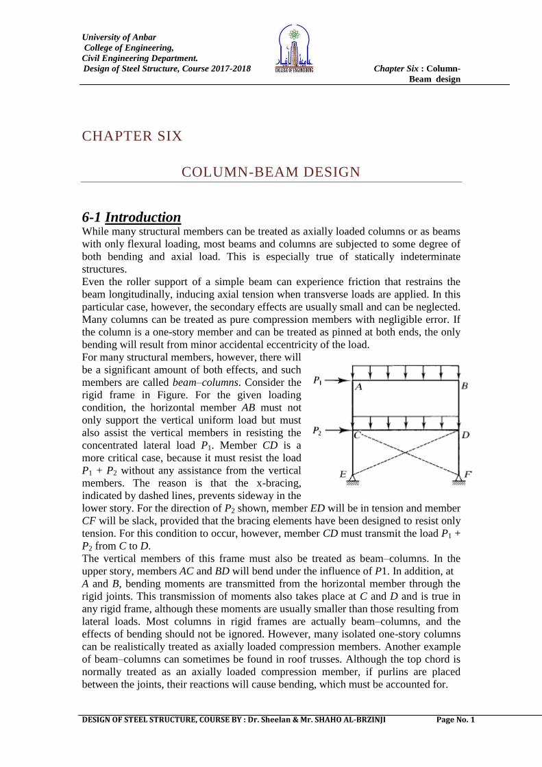
For many structural members, however, there will
be a significant amount of both effects, and such
members are called beam–columns. Consider the
rigid frame in Figure. For the given loading
condition, the horizontal member AB must not
only support the vertical uniform load but must
also assist the vertical members in resisting the
concentrated lateral load P1. Member CD is a
more critical case, because it must resist the load
P1 + P2 without any assistance from the vertical
members. The reason is that the x-bracing,
indicated by dashed lines, prevents sideway in the
lower story. For the direction of P2 shown, member ED will be in tension and member
CF will be slack, provided that the bracing elements have been designed to resist only
tension. For this condition to occur, however, member CD must transmit the load P1 +
P2 from C to D.
The vertical members of this frame must also be treated as beam–columns. In the
upper story, members AC and BD will bend under the influence of P1. In addition, at
A and B, bending moments are transmitted from the horizontal member through the
rigid joints. This transmission of moments also takes place at C and D and is true in
any rigid frame, although these moments are usually smaller than those resulting from
lateral loads. Most columns in rigid frames are actually beam–columns, and the
effects of bending should not be ignored. However, many isolated one-story columns
can be realistically treated as axially loaded compression members. Another example
of beam–columns can sometimes be found in roof trusses. Although the top chord is
normally treated as an axially loaded compression member, if purlins are placed
between the joints, their reactions will cause bending, which must be accounted for.
University of Anbar
College of Engineering,
Civil Engineering Department.
Design of Steel Structure, Course 2017-2018 Chapter Six : Column-
Beam design
DESIGN OF STEEL STRUCTURE, COURSE BY : Dr. Sheelan & Mr. SHAHO AL-BRZINJI Page No. 2
6-2 Interaction Formulas The relationship between required and available strengths may be expressed as
For compression members, the strengths are axial forces. For example, for LRFD
These expressions can be written in the general form:
where
Pr = required axial strength
Pc = available axial strength
If both bending and axial compression are acting, the interaction formula would be
Where: Mr required moment strength = Mu
Mc = available moment strength = φb Mn
For biaxial bending, there will be two moment ratios:
where the x and y subscripts refer to bending about the x and y axes.
For large axial load, the bending term is slightly reduced. The AISC requirements are
given in Chapter H, ―Design of Members for Combined Forces and Torsion,‖ and are
summarized as follows:
University of Anbar
College of Engineering,
Civil Engineering Department.
Design of Steel Structure, Course 2017-2018 Chapter Six : Column-
Beam design
DESIGN OF STEEL STRUCTURE, COURSE BY : Dr. Sheelan & Mr. SHAHO AL-BRZINJI Page No. 3
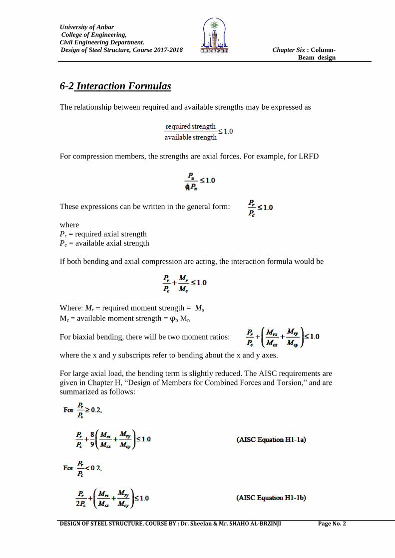
EXAMPLE 6-1: The beam–column shown in Figure is pinned at
both ends and is subjected to the loads shown. Bending is about the
strong axis. Determine whether this member satisfies the appropriate
AISC Specification interaction equation.
SOLUTION:
From the column load tables, the axial compressive design strength
of a W10 × 49 with Fy = 50 ksi and an effective length of KyL = 1.0
× 17 = 17' is φc Pn = 405 kips (Table 4-1, pp. 4-20)
Since bending is about the strong axis, the design moment:
For an unbraced length Lb = 17 ':
Lp= 8.97 ', Lr = 31.6 ', φb Mp = 226.5, BF= 3.67 (Table 3-2, pp. 3-18)
b p b[ (L L )b n b b px pxM C M BF M
φb Mn = 197 ft-kips
For the end conditions and loading of this problem, Cb = 1.32
For Cb = 1.32, the design strength is
φb Mn = Cb × 197 = 1.32(197) = 260 ft-kips > φb Mp = 226.5
φb Mn = 226.5 ft-kips
Factored loads:
Pu = 1.2PD + 1.6PL = 1.2(35) + 1.6(99) = 200.4 kips
Qu = 1.2QD + 1.6QL = 1.2(5) + 1.6(12) = 25.2 kips
The maximum bending moment occurs at midheight, so
Determine which interaction equation controls:
This member satisfies the AISC Specification.
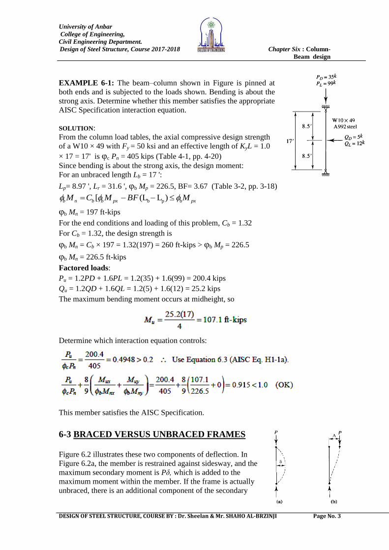
6-3 BRACED VERSUS UNBRACED FRAMES
Figure 6.2 illustrates these two components of deflection. In
Figure 6.2a, the member is restrained against sidesway, and the
maximum secondary moment is Pδ, which is added to the
maximum moment within the member. If the frame is actually
unbraced, there is an additional component of the secondary
University of Anbar
College of Engineering,
Civil Engineering Department.
Design of Steel Structure, Course 2017-2018 Chapter Six : Column-
Beam design
DESIGN OF STEEL STRUCTURE, COURSE BY : Dr. Sheelan & Mr. SHAHO AL-BRZINJI Page No. 4
moment, shown in Figure 6.2b, that is caused by sidesway. This secondary moment
has a maximum value of PΔ, which represents an amplification of the end moment.
To approximate these two effects, two amplification factors, B1 and B2, are used
for the two types of moments. The amplified moment to be used in design is
computed from the loads and moments as follows (x and y subscripts are not used
here; amplified moments must be computed in the following manner for each axis
about which there are moments):
Mr B1Mnt B2Mlt (AISC Equation A-8-1)
Where: Mr required moment strength Mu for LRFD
Mnt maximum moment assuming that no sidesway occurs, whether the frame is
actually braced or not (the subscript nt is for ―no translation‖). Mnt will be a factored
load moment for LRFD
Mlt maximum moment caused by sidesway (the subscript lt is for ―lateral
translation‖). This moment can be caused by lateral loads or by unbalanced gravity
loads. Gravity load can produce sidesway if the frame is unsymmetrical or if the
gravity loads are unsymmetrically placed. Mlt will be zero if the frame is actually
braced. For LRFD, Mlt will be a factored load moment
B1 amplification factor for the moments occurring in the member when it is braced
against sidesway (P-δ moments).
B2 amplification factor for the moments resulting from sidesway (P-Δmoments).
In addition to the required moment strength, the required axial strength must account
for second-order effects. The required axial strength is affected by the displaced
geometry of the structure during loading. This is not an issue with member
displacement (δ), but it is with joint displacement (Δ). The required axial compressive
strength is given by
Pr Pnt B2Plt (AISC Equation A-8-2)
Where: Pnt axial load corresponding to the braced condition
Plt axial load corresponding to the sidesway condition
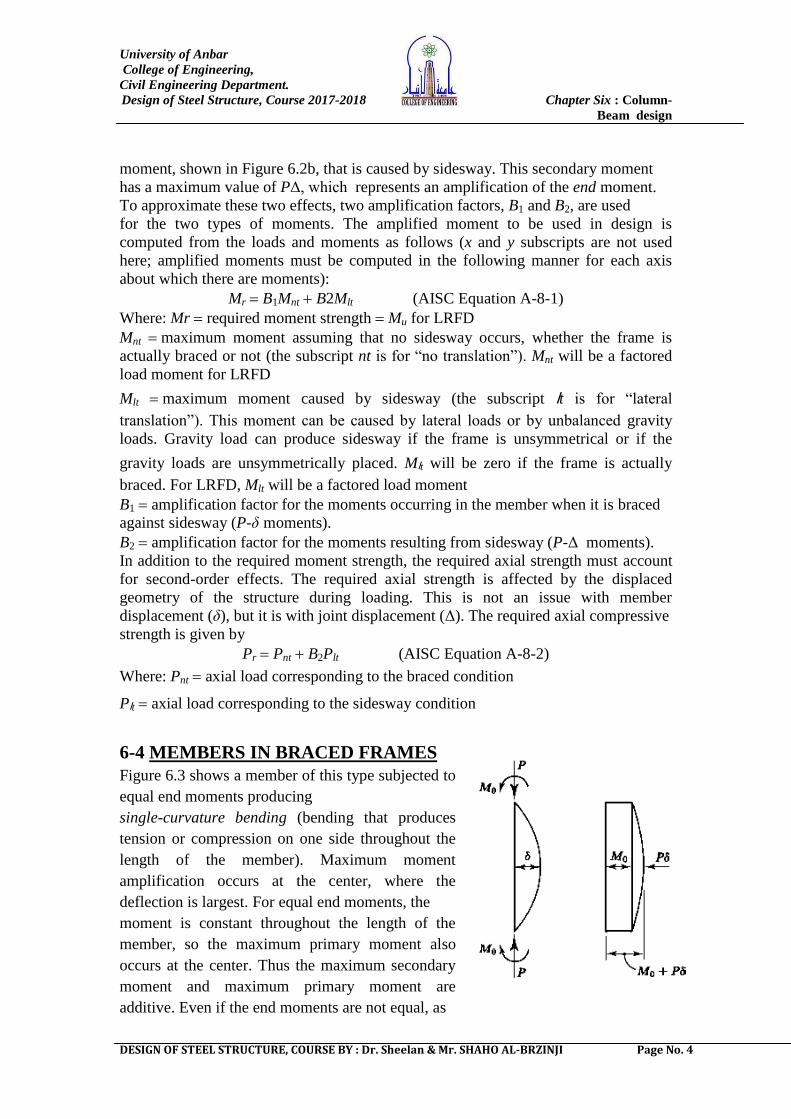
6-4 MEMBERS IN BRACED FRAMES
Figure 6.3 shows a member of this type subjected to
equal end moments producing
single-curvature bending (bending that produces
tension or compression on one side throughout the
length of the member). Maximum moment
amplification occurs at the center, where the
deflection is largest. For equal end moments, the
moment is constant throughout the length of the
member, so the maximum primary moment also
occurs at the center. Thus the maximum secondary
moment and maximum primary moment are
additive. Even if the end moments are not equal, as
University of Anbar
College of Engineering,
Civil Engineering Department.
Design of Steel Structure, Course 2017-2018 Chapter Six : Column-
Beam design
DESIGN OF STEEL STRUCTURE, COURSE BY : Dr. Sheelan & Mr. SHAHO AL-BRZINJI Page No. 5
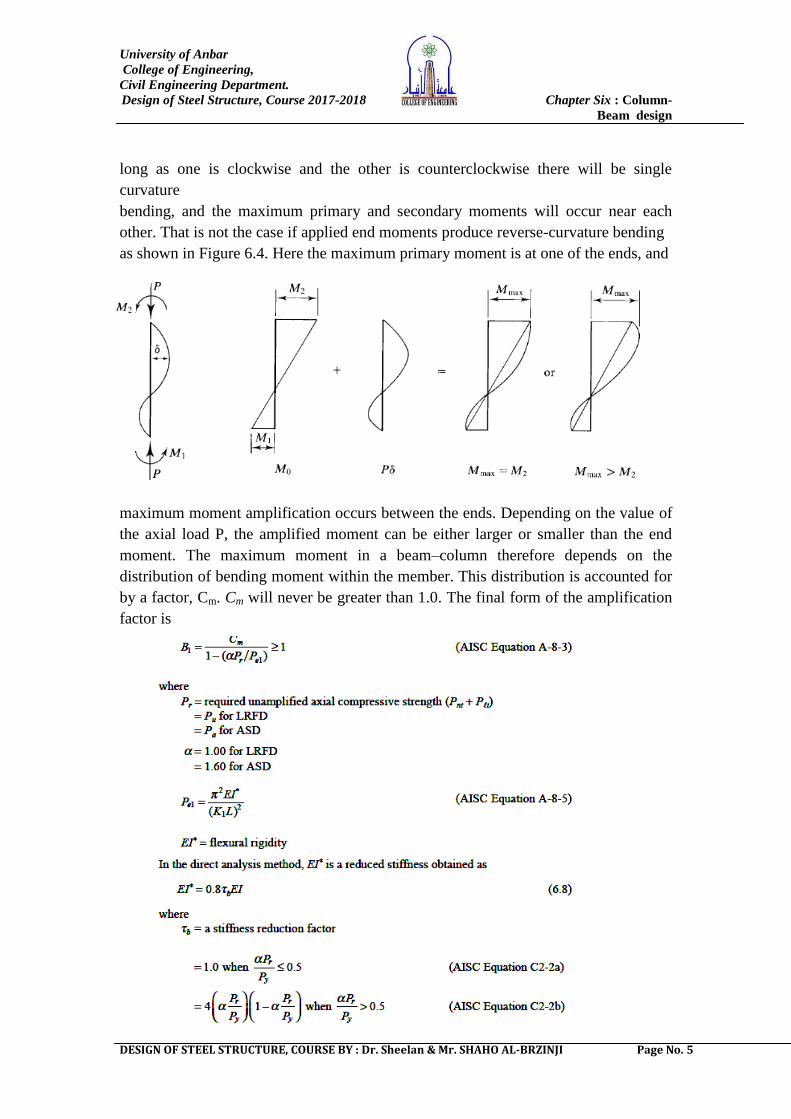
long as one is clockwise and the other is counterclockwise there will be single
curvature
bending, and the maximum primary and secondary moments will occur near each
other. That is not the case if applied end moments produce reverse-curvature bending
as shown in Figure 6.4. Here the maximum primary moment is at one of the ends, and
maximum moment amplification occurs between the ends. Depending on the value of
the axial load P, the amplified moment can be either larger or smaller than the end
moment. The maximum moment in a beam–column therefore depends on the
distribution of bending moment within the member. This distribution is accounted for
by a factor, Cm. Cm will never be greater than 1.0. The final form of the amplification
factor is
University of Anbar
College of Engineering,
Civil Engineering Department.
Design of Steel Structure, Course 2017-2018 Chapter Six : Column-
Beam design
DESIGN OF STEEL STRUCTURE, COURSE BY : Dr. Sheelan & Mr. SHAHO AL-BRZINJI Page No. 6
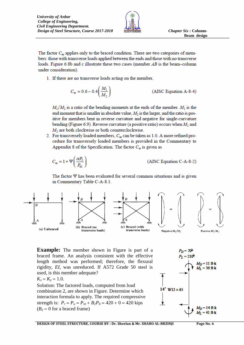
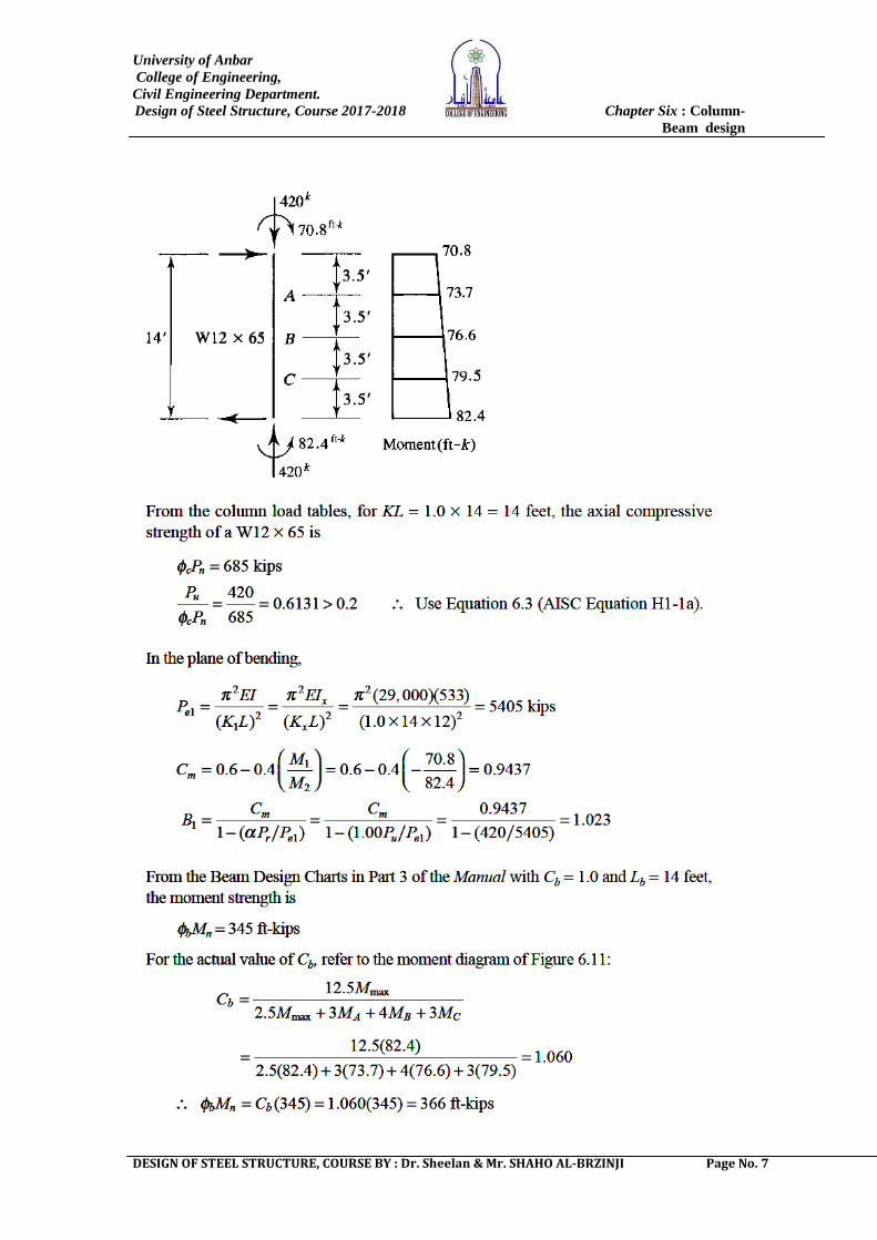
Example: The member shown in Figure is part of a
braced frame. An analysis consistent with the effective
length method was performed; therefore, the flexural
rigidity, EI, was unreduced. If A572 Grade 50 steel is
used, is this member adequate?
Kx Ky 1.0.
Solution: The factored loads, computed from load
combination 2, are shown in Figure. Determine which
interaction formula to apply. The required compressive
strength is: Pr Pu Pnt B2Plt 420 0 420 kips
(B2 0 for a braced frame)
University of Anbar
College of Engineering,
Civil Engineering Department.
Design of Steel Structure, Course 2017-2018 Chapter Six : Column-
Beam design
DESIGN OF STEEL STRUCTURE, COURSE BY : Dr. Sheelan & Mr. SHAHO AL-BRZINJI Page No. 7
University of Anbar
College of Engineering,
Civil Engineering Department.
Design of Steel Structure, Course 2017-2018 Chapter Six : Column-
Beam design
DESIGN OF STEEL STRUCTURE, COURSE BY : Dr. Sheelan & Mr. SHAHO AL-BRZINJI Page No. 8
Example: The horizontal beam–column
shown in Figure is subject to the service live
loads shown. This member is laterally braced at
its ends, and bending is about the x-axis. Check
for compliance with the AISC Specification. Kx
Ky 1.0.
Solution:
The factored axial load is: Pu = 1.6(28) = 44.8 kips
The factored transverse loads and bending moment are: Qu = 1.6(28) = 44.8 kips
wu = 1.2(0.035) = 0.042 kips-ft
University of Anbar
College of Engineering,
Civil Engineering Department.
Design of Steel Structure, Course 2017-2018 Chapter Six : Column-
Beam design
DESIGN OF STEEL STRUCTURE, COURSE BY : Dr. Sheelan & Mr. SHAHO AL-BRZINJI Page No. 9
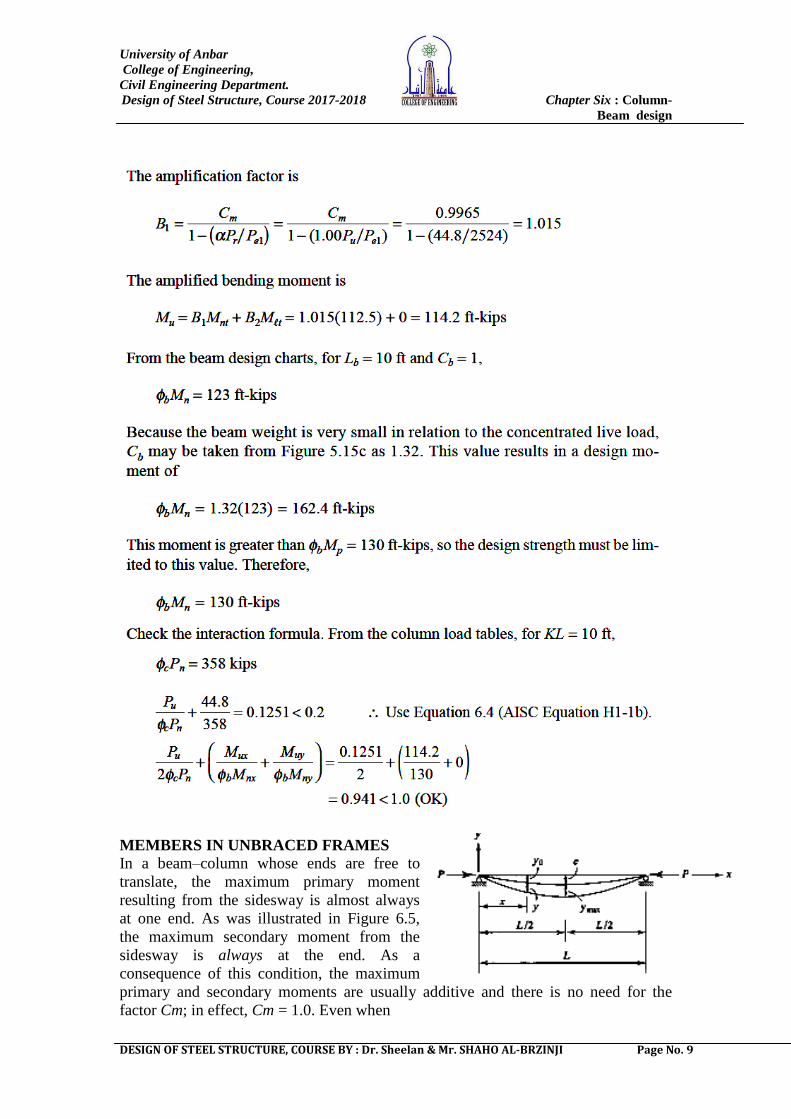
MEMBERS IN UNBRACED FRAMES
In a beam–column whose ends are free to
translate, the maximum primary moment
resulting from the sidesway is almost always
at one end. As was illustrated in Figure 6.5,
the maximum secondary moment from the
sidesway is always at the end. As a
consequence of this condition, the maximum
primary and secondary moments are usually additive and there is no need for the
factor Cm; in effect, Cm = 1.0. Even when
University of Anbar
College of Engineering,
Civil Engineering Department.
Design of Steel Structure, Course 2017-2018 Chapter Six : Column-
Beam design
DESIGN OF STEEL STRUCTURE, COURSE BY : Dr. Sheelan & Mr. SHAHO AL-BRZINJI Page No. 10
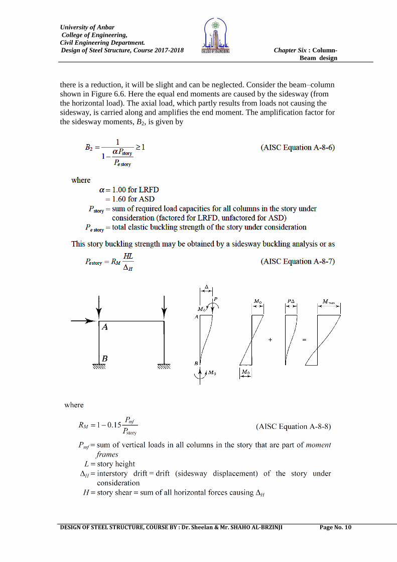
there is a reduction, it will be slight and can be neglected. Consider the beam–column
shown in Figure 6.6. Here the equal end moments are caused by the sidesway (from
the horizontal load). The axial load, which partly results from loads not causing the
sidesway, is carried along and amplifies the end moment. The amplification factor for
the sidesway moments, B2, is given by
University of Anbar
College of Engineering,
Civil Engineering Department.
Design of Steel Structure, Course 2017-2018 Chapter Six : Column-
Beam design
DESIGN OF STEEL STRUCTURE, COURSE BY : Dr. Sheelan & Mr. SHAHO AL-BRZINJI Page No. 11
Note that, if there are no moment frames in the story, Pmf = 0 and RM= 1.0. If all of the
columns in the story are members of moment frames, then Pmf = Pstory and RM = 0.85.
The rationale for using the total story load and strength is that B2 applies to unbraced
frames, and if sidesway is going to occur, all columns in the story must sway
simultaneously. In most cases, the structure will be made up of plane frames, so Pstory
and Pe story are for the columns within a story of the frame, and the lateral loads H
are the lateral loads acting on the frame at and above the story. With ΔH caused by H,
the ratio H/ΔH can be based on either factored or unfactored loads. In situations
where Mnt and M t act at two different points on the member, as in Figure 6.4, AISC
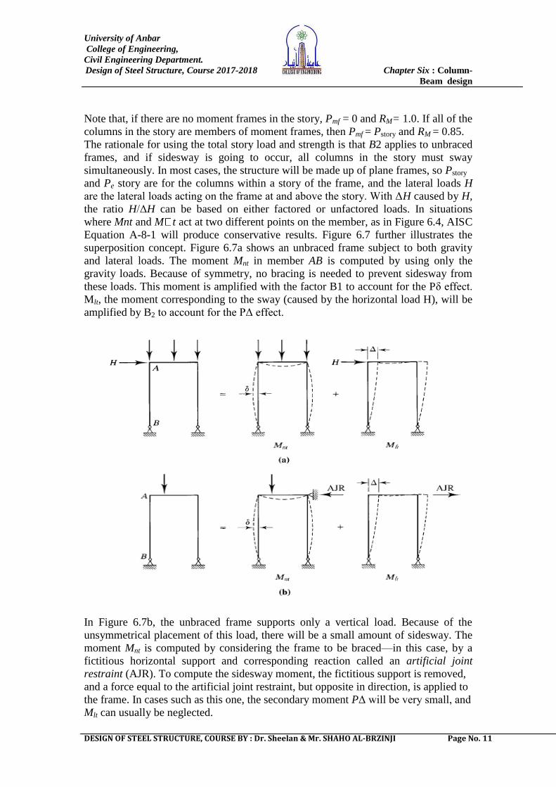
Equation A-8-1 will produce conservative results. Figure 6.7 further illustrates the
superposition concept. Figure 6.7a shows an unbraced frame subject to both gravity
and lateral loads. The moment Mnt in member AB is computed by using only the
gravity loads. Because of symmetry, no bracing is needed to prevent sidesway from
these loads. This moment is amplified with the factor B1 to account for the Pδ effect.
Mlt, the moment corresponding to the sway (caused by the horizontal load H), will be
amplified by B2 to account for the PΔ effect.
In Figure 6.7b, the unbraced frame supports only a vertical load. Because of the
unsymmetrical placement of this load, there will be a small amount of sidesway. The
moment Mnt is computed by considering the frame to be braced—in this case, by a
fictitious horizontal support and corresponding reaction called an artificial joint
restraint (AJR). To compute the sidesway moment, the fictitious support is removed,
and a force equal to the artificial joint restraint, but opposite in direction, is applied to
the frame. In cases such as this one, the secondary moment PΔ will be very small, and
Mlt can usually be neglected.
University of Anbar
College of Engineering,
Civil Engineering Department.
Design of Steel Structure, Course 2017-2018 Chapter Six : Column-
Beam design
DESIGN OF STEEL STRUCTURE, COURSE BY : Dr. Sheelan & Mr. SHAHO AL-BRZINJI Page No. 12
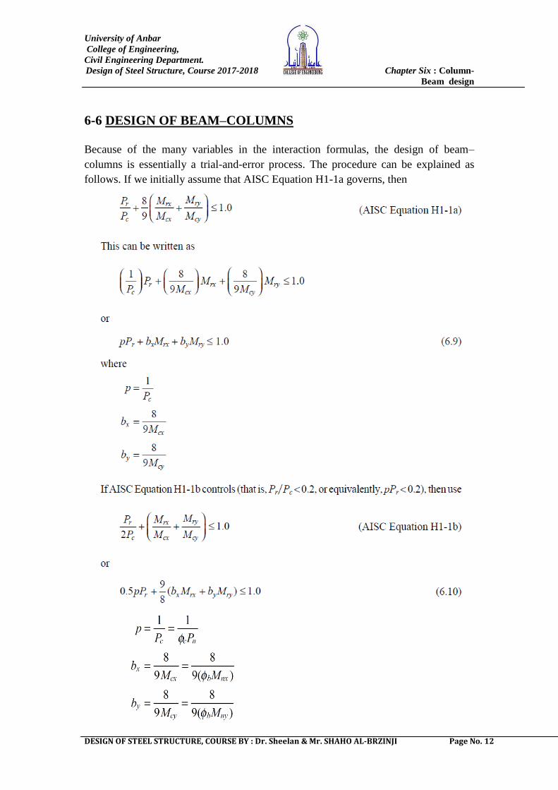
6-6 DESIGN OF BEAM–COLUMNS
Because of the many variables in the interaction formulas, the design of beam–
columns is essentially a trial-and-error process. The procedure can be explained as
follows. If we initially assume that AISC Equation H1-1a governs, then
University of Anbar
College of Engineering,
Civil Engineering Department.
Design of Steel Structure, Course 2017-2018 Chapter Six : Column-
Beam design
DESIGN OF STEEL STRUCTURE, COURSE BY : Dr. Sheelan & Mr. SHAHO AL-BRZINJI Page No. 13
Table 6-1 gives values of p, bx, and by for all W shapes listed in Part 1 of the Manual,
―Dimensions and Properties,‖ except for those smaller than W8. The values of Cb, B1,
and B2 must be calculated independently for use in the computation of Mr (Mu for
LRFD). The procedure for design is as follows:
1. Select a trial shape from Table 6-1 of the Manual.
2. Use the effective length KL to select p, and use the unbraced length Lb to select
bx (the constant by determines the weak axis bending strength, so it is independent of
the unbraced length). The values of the constants are based on the assumption that
weak axis buckling controls the axial compressive strength and that Cb = 1.0.
3. Compute pPr. If this is greater than or equal to 0.2, use interaction Equation
6.9. If pPr is less than 0.2, use Equation 6.10.
4. Evaluate the selected interaction equation with the values of p, bx, and by for the
trial shape.
5. If the result is not very close to 1.0, try another shape. By examining the value of
each term in Equation 6.9 or 6.10, you can gain insight into which constants need to
be larger or smaller.
6. Continue the process until a shape is found that gives an interaction equation result
less than 1.0 and close to 1.0 (greater than 0.9).
Verification of assumptions:
If strong axis buckling controls the compressive strength, use an effective
length of
to obtain p from Table 6-1.
If Cb is not equal to 1.0, the value of bx must be adjusted.
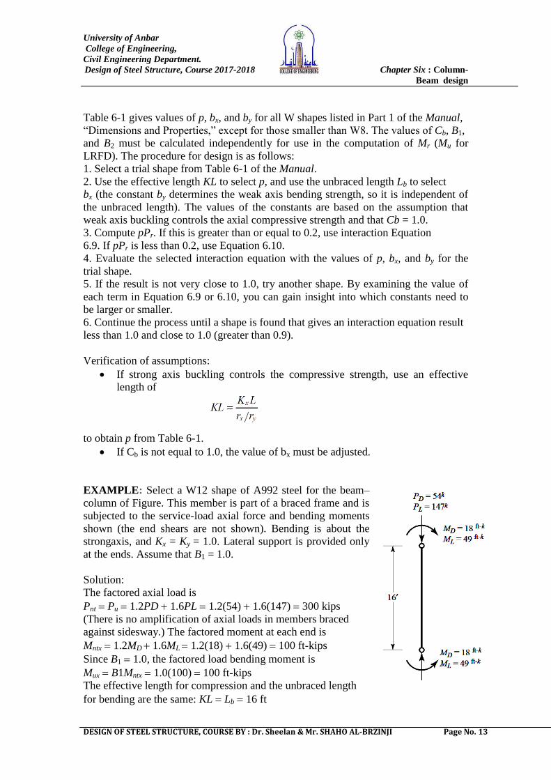
EXAMPLE: Select a W12 shape of A992 steel for the beam–
column of Figure. This member is part of a braced frame and is
subjected to the service-load axial force and bending moments
shown (the end shears are not shown). Bending is about the
strongaxis, and Kx = Ky = 1.0. Lateral support is provided only
at the ends. Assume that B1 = 1.0.
Solution:
The factored axial load is
Pnt Pu 1.2PD 1.6PL 1.2(54) 1.6(147) 300 kips
(There is no amplification of axial loads in members braced
against sidesway.) The factored moment at each end is
Mntx 1.2MD 1.6ML 1.2(18) 1.6(49) 100 ft-kips
Since B1 1.0, the factored load bending moment is
Mux B1Mntx 1.0(100) 100 ft-kips
The effective length for compression and the unbraced length
for bending are the same: KL Lb 16 ft
University of Anbar
College of Engineering,
Civil Engineering Department.
Design of Steel Structure, Course 2017-2018 Chapter Six : Column-
Beam design
DESIGN OF STEEL STRUCTURE, COURSE BY : Dr. Sheelan & Mr. SHAHO AL-BRZINJI Page No. 14