chapter news information displayinformationdisplay.org/portals/informationdisplay...chapter news...
TRANSCRIPT

Chapter News
MINNEAPOLIS/ ST. PAUL CHAPTER-Thanks to our reliable friend, Vern Born, Director of SID Central Division, we have another picture of a happy group at a chapter meeting. Vern took this picture in November and sent it to you r Editor with an amusing letter penned whi le flying back to the Twin Cities from New York: Dateline, Over Lake Erie 5 p.m., January 16, 1981 . The weather was apparently rough enough so that Vern rated his chances of making the SID meeting that evening at 50%. Our hero did it, and enjoyed the demonstration at National Weather Service. In a report on this meeting approved by Russell E. lngvaldsen, Chapter Treasurer, and prepared by Will Hailer, Secretary, 27 SID Members and guests saw a computer display of weather data including 200 square mile grids covering the entire U.S. Dale Branch, meteorologist in charge of man-machine interface and electronic computer display at NWS, was the speaker.
At CPT Corp, about half the group of SID Members and guests from MINNEAPOLIS/ ST PAUL Chapter who attended an Interesting meeting in November 1980.
DELAWARE VALLEY CHAPTER on January 29 was treated to a talk by Dr. Derick Jones of Electronic Display Systems, Hatfield, PA. Topic was "Liquid Crystal Displays",
INFORMATION DISPLAY MARCH 1981 SOCIETY FOR INFORMATION DISPLAY 654 NORTH SEPULVEDA BOULEVARD LOS ANGELES, CALIFORNIA 90049
and 25 attendees enjoyed demonstrations at EDS plant in Hatfie ld. Th anks to C.P. Halsted, Chapter Chairman, and N. Rubin , Chapter Secretary, for regular information on SID meetings in your area!
LOS ANGELES CHAPTER has had exceptionally good SID meetings during this 1980-81 period, thanks to Gordon Kramer, Program Cha irman. Gordon is also prompt about supplying data to your Editor for this page. Oh, that there were more like h im .. .. On February 25, SID Members enjoyed a tour of the control tower at LAX (Los Angeles Internationa l Airport), one of the world 's busiest airports as most SID travelers know. Ivan Hunt of the tower staff guided SID Members and guests through the fac il ity, described the display systems used for air traffic control , provided some classroom instruction for our numerous flying buffs, and led the large group to the LAX radar tracking fac il ity, TRACON. Hunt was a most entertaining host, dealing w ith topics interesting to practically every SID member.
SAN DIEGO CHAPTER news is as reliable as the rain on the plain in Spain, thanks to George Unangst. (He not only collects bucks, he's willing to spend 15¢ frequently to send Chapter News to June Friend or me. Only the news comes in bunches, like bananas.) On December 16, the SID group went to world -famous San Diego Zoo in Balboa Park and enjoyed a discussion on " Special Photographic Techniques-How Zoo Animals Are Photographed" by B. Green of th e zoo staff . ... R.W. " Bob" Netting, marketing manager of the Reuben H. Fleet Space Theater and Science Center, Balboa Park, provided a fascinating film , lecture, and tour of the facility for a large SID group on January 21. One feature described and displayed was the use of pinhole apertures for planetarium projectors .. . . Then on February 10, Dr. William V. Smith, manager of the laser laboratory, and Terry Bochanty, marketing representative, both of DiscoVision Associates, Costa Mesa, presented an excellent program. The principles of the optical disc technology developed by MCA DiscoVision (now DiscoVision Associates) and Phillips were described.
Non-Profit Organization U.S. Postage Paid Permit No. 29744 Los Angeles, Ca.
At...4~l n:m:::~ u 33
28/ lnformation Display 3-81
633 MICHIJA~ AVE. £VA~S!O~. IL bl2J2
Information Display The Official Journal of t he Society For Information Display MARCH 1981
Collection of Magnetic Shields for encapsulating vari ous sizes of CRTs is shown w ith Richard D. Vance, president, Ad-Vance Magnetics, Inc., Rochester, Indiana. Shield fabrication involves deep drawing, meta l spinning, and heliarc and spot we lding. Materials range from 0.025 to 0.062 AD-M U-78 high permeability shielding alloy.
A unique CRT shield w ith support mounts and term ina ls is in SID member Rick Vance's hand. The accompanying article beginning on page 3 discusses protection against the earth 's magnetic field, denser packaging problems, unexpected hidden hazards to equipment performance in modern construction, solutions to certain CRT shielding problems, and the pros and cons of low cost "i nstant" CRT shields made of foil.
FRONT COVER MATERIAL WELCOMED: Every month Information Display usually features one or more active members of SID and the products w it h w hich they are most closely associated. Please send a glossy print and appropriate captions so that you, too, can be on our front cover. Send your material to Ted Lucas, Editor, P.O. Box 852, Cedar Glen, CA92321 , or to our National Off ice Manager, June Friend, for Information Display, 654 North Sepulveda Blvd., Los Angeles, CA 90049. Next deadline for material f rom you is April 1 0. If you miss that, try forthe May issue, NOTE: We also welcome feature articles on interesting projects.
.. ..

OFFICERS
President .......... ...... • ...... . ....... T. DuPuis Vice President .........•......... ... ..... V.J. Fowler Secretary ............... ..... ....... ... G.F. Carroll T reasurer .............. ............ • ... I.F. Chang
DIRECTORS Central ............. ................ ... V.A. Born M idwest .................. . ............ J. Markin Northeast ....... • • . .. ...•....... •• ..... P .Pieshko
W.G . Mulley G.R. Spencer
Western. . . . . . . . . . . . . . . . . . . . . . . . . . . ... H .P. Sherman L.E. Tannas, Jr.
R .E. T homan Japan ................... . . .. .. . . .. .. M . Ashikawa Past President ...... . .... . . . . .. . . ....... B.J . Lechner
COMMITTEE CHAIRMEN Academic . . . . . ...... . ... . . . .. H.G. Slottow AFIPS Representative .. . . . .. • . • . • .... . .... C.P. Crocetti A rchives/Historian ... . . . . ... ........ .. ... . J.A. Clifton Bylaws ..... . ..... .... . . . •• .. . ... .. . .. R.C. Klein Symposium Advisory Committee .. ...• . ....... J.A. van Raalte
Symposium Consultant. .... . .•. ... ... ...... L. Winner Definit ions & Standards ..... . .. .. ........ .. N.W. Patrick Honors & Awards . . . . . . . . . . . • . . . . . . . . . . . . . I . Reingold Membership ....... ... • .. • ... • . ....... L .M. Seeberger Nominations .. .. . . .......... . .. • .... . .. B.J . Lechner Publications .......... ........ .. . . ...... T .V. Curran
Information Display Editor . . . • . . . . . . . . . ... T . Lucas Proceedings Editor . . . . . . . . . . . . . . . . . . S. Sherr
CHAPTER OFFICERS Chap ter Chairman
Bay Area. . • • . . . . . . . . . . •. ... G. Carroll Del . Valley . . . . . . . . • . . . • . . . . . . . . . C. Halstead Japan . . . . . . . . • . • • • . . • . . . . . . .. ... . I . Ohishi Los Angeles . . . . . . . . • . . . . . . . . . . . . . . . • . . . . T . Lim Mid-Atlantic ... .. .•........ . ... .. ... • ... J. St apleton Midwest .. . .. . . • .•... . . ... . .... . . .. . ... W. Martin Minn./St. Paul . . . . • . • • . . . . . . .. . R . Jamieson New England ... .. • . . ... . • . .. ..... . . ..... T . Cheek San Diego ........... . . . . .. . . .... . . . . . J. Lipscombe
SOCIETY FOR INFORMATION DISPLAY 654 No. Sepulveda Blvd. , Los Angeles, Calif. 90049
(213) 4 72-3550
June Friend, National Office Manager
Sustaining Members ASEA, DPET. YLDK S-721 83 Vasteras. Sweden AUDIOTRONICS VIDEO DISPLAY DIVISION 8299 Central Ave .• N.E .. Spring Lake Park, MN 55432 AYDIN CONTROLS 414 Commerce Drive, Fort Washington, PA 19034 BALL ElECTRONIC DISPLAY DIVISION 4501 Ball Road, N.E., Circle Pines, MN 55014 BENDIX CORPORATION Flight Systems Division, Teterboro, NJ 07608 BIDCO, INC. CRT Display Electronics. 18 Milford Dr .. Plainview, NY 11803 BURROUGHS OEM CORPORATION Plainfield Plant, Pla infield, NJ 07061 CARDION ELECTRONICS A Division of General Signa l Corporation Long Island Expressway, Woodbury, NY 11 797 CELCO (Constantine Engineering Labs. Co.) 70 Constantine Drive. Mahwah, NJ 07430 C HERRY ELECTRICAL PRODUCTS CORP. 3600 Sunset Ave .. Waukegan. IL 60085 C LIFTON PRECISION/ SPECIA L DEVICES 5100 State Road. Drexel Hill, PA 19026 CLINTON ELECTRONICS CORPORATION 6701 Cl inton Road. Loves Park, IL 6111 1 CONRAC CORPORATION 3 Landmark Square. Stamford, CT 06901 DALE ELECTRONI CS P.O. Box 609, Columbus, NE 68601
2/ lnformation Display 3 -81
DIEHL RESEARCH CENTER DIEHL CORPORATION 65 Commerce Road, Stamford, CT 06902 DISPLAY COMPONENTS, INC. 334 Littleton Road, Westford, MA 01886 DuMONT DIVISION, Division of Thomson·CSF Component Co. 750 Bloomfield Avenue, Clifton, NJ 07015 ELECTRONIC DISPLAY SYSTEM S, INC. 2321 Topaz Drive. P.O. Box 280. Hatfield, PA 19440 FORD AEROSPACE AND COMMUNICATIONS CORP. WDL Division, Palo Alto, CA 94302 GENERAL ATRONICS CORP. Subsidiary of Magnavox Govt. & Industrial Electronics Co. 1200 E. Mermaid Lane, Philadelphia, PA 19 11 8 GENERAL ELECTRIC COMPANY Aerospace Control Systems Department P.O. Box 5000, Binghampton, NY 13902 GEROME MANUFACTURING CO., INC. P.O. Box 1089, Oliver Road. Uniontown, PA 15401 GML INFORMATION SERVICES 594 Marrett Road, Lexington, MA 02173 GTE LABORATORIES, INC. 40 Sylvan Road, Waltham. MA 02254 HARTMAN SYSTEMS Division of A -T-O Inc., 360 Wolf Hill Road, Huntington Station, NY 11 746 HAZELTINE CORPORATION Greenlawn, NY 11740 HUGHES AIRCRAFT COMPANY Culver City, CA 90230 HYCOM, INCORPORATED 16841 Armstrong Ave., Irvine, CA 92714 IBM CORPORATION Armonk, NY 1 0504 IMARO, INC. West Royalty Industrial Park, Charlottetown, P.R.I., Canada C1 E 180 INDUSTRIAl ElECTRONIC ENGINEERS, INC. 7740 Lemona Ave .. Van Nuys, CA 91405 INFORMATION CONTROL CORPORATION 9610 Bellanca Ave .. Los Angeles, CA 90045 INTERSTATE ELECTRONICS CORPORATION Display Product Operations 1001 E. Ball Road, Anaheim, CA 92803 ISE ELECTRONICS CORPORATION P.O. Box 46, lse, Mie, Japan MITSUBISHI ELECTR ONICS AMERICA. INC. 2200 W. Artesia, Compton, CA 90220 OPTICAL COATING lABORATORY, INC . P.O. Box 1599, Santa Rosa. CA 95402 ORWIN ASSOCIATES, INC. 88 Seabro Avenue, Amityville, New York 11701 PHOTO RESEARCH DIVISON Kollmorgen Corporation 3000 N. Hollywood Way, Burbank, CA 91505 PHOTONICS TECHNOLOGY P.O. Box 432, Luckey, OH 43443 PTK CORPORATI ON 1173 Los Olivos Ave .• Los Osos, CA 93402 RANK ELECTRONIC TUBES RANK PRECISION INDUSTRIES LIMITED Sidcup By-Pass, Sidcup, Kent, England RAYTHEON COMPANY Industrial Components Operation 465 Centre Street. Quincy, MA02169 SAl TECHNOLOGY COMPANY 4060 Sorrento Valley Blvd., San Diego, CA 92121 SANDERS ASSOCIATES. INC . D.W. Highway South, Nashua, NH' 03061 SCHOTT OPTICAl GLASS. INC. 400 York Ave., Duryea, PA 18642 SGL HOMALITE A Division of SGL Industries, 11 Brookside Drive. Wilmington, DE 19804 SIEMENS AG Components Group, 73 Balanstr. D8000, Munich, West Germany SINGER-LIBRASCOPE Aerospace & Marine Systems Group, 833 Sonora Avenue, Glendale, CA 91201 SMITH ENGINEERING 3232 Nebraska Ave., Santa Monica, CA 90404 SONY CORPORATION 7-35 Kitashinagawa 6-chome Shinagawa-ku Tokyo, 141 Japan SYNTRONIC INSTRUMENTS, INC. 100 Industrial Road, Addison, IL 60101 TEKTRONIX, INC. Information Display Products, P.O. Box 500, Beaverton, OR 97007 TEXAS INSTRUMENTS, INCORPORATED P.O. Box 225936, MS 147, Dallas, TX 75265 THOMAS ELECTRONICS, INC. 100 Riverview Drive, Wayne, NJ 07470 THORN-BRIMAR LTD. Greenside Way, Chadderton Industrial Estate. Middleton, Manchester M24 1 SN, England TRANS COM Unit of Sundstrand Corporation 3100 Pullman St., Costa Mesa. CA 92626 XEROX C ORPORATION Palo Alto Research Center, Palo Alto, CA 94304 ZENITH RADIO CORPORATI ON 1000 Milwaukee Ave., Glenview, IL 60025
J
Who Needs Magnetic Shielding? You Do if Magnetic Interference
Prevents Your Product From Functioning Optimally
by Richard D . Vance, President, Ad-Vance Magnetics. Inc.
When magnetic interference is present, it can cause an unwelcome deterrent to f ull f unction ing of products susceptible to it. Sometimes this problem may be foreseen and avoided by mandat ing proper magnetic shielding during the design stage. Otherwise, magnetic interference may cause consternation by appearing unexpectedly during the production or testing stages. At worst, it evidences itself when t he customer uses the product. In any event. the consequential reduction in expected top performance from components and systems req ui res the addition of magnetic shielding to divert the interfering fields.
Protection Against The Earth 's Magnetic Field
The pervasive earth 's magnetic field is not a factor in some applications. However, it can be detrimental to certain specialized applications. One example is a 0.025" thick high permeability double cylinder shield used to t ransport rocks. degaussed of the present earth 's field, safely to a site sh ielded aga inst the earth 's magnetic f ield. In the double cylinder sh ield illustrated by Figure 1 the requi red attenuation is approximately 1,000 times, w ith the cyl inder in the field transverse to its axis. The geometric increase in shielding effectiveness of two cylinders vs. a sing le cylinder is expressed in this equat ion: One cylinder static shield effectiveness, s,,
given by s ,= 1 + 1~ t = thickness of cylinder R = outer radius of cylinder in same units of length
Double cylinder static sh ield effectiveness, S'
S' = 1 + St + S2+ (St) (S2) (1-&) A2
A 1= Cross section area (normal to flux) of outer surface of fi rst cylinder
A2= Cross section area (normal to f lux) of outer surface of second cylinder
(1 - : :) = 0 .5 usually.
Double cylinder construction of 0 .025" high permeabi l ity fabricated alloy provides the requ ired strength and shape stability. Aluminum bar spacers separating cylinders have milled reliefs for demagnetizing coils. The outer cylinder radius is~times the inner cylinder radius, with both cylinders having t he same thickness.
Denser Packaging Problems
The closeness of components in ever denser modern systems makes magnetic radiation problems worse. Offending fie lds may originate in a small motor, or generator, or transformer, for example. Affected components may include CRTs, scan converter t ubes, storage tubes. wea ther radar display tubes, high resolution v ideo recorder head assemblies, etc .
Ease of access is the deciding factor on w hether to shield the radiating component or the affected component . It is recommended that the radiation source be sh ielded when practica l. However, in very close spacing, AC
shielding should be achieved by absorpt ion (magnetic hysteresis). This is because the reflection mechanism, which is a major cost-free sh ielding effect at plane wave conditions, changes sign and becomes counter-productive "antenna gain" .
Figure 1
Figure 2
ADVERTISERS' INDEX Ad-Vance Magnetics, Inc . .... ... ... . ... . . . ..... 22
(Burton Browne Adv.)
Ce lco (Constanti ne Eng ineering Labs., Co.) . ..... . 26 (Stano Advertising )
Eagle Magnetic Company, Inc . ... .. ... . . .... . ... 27 (Rohr Advertising)
Keltron Corportion ...... .. .. .. . .. .. .......... . 19 (Appleton-Kingston, Inc.)
Static Systems Corp .... . ...... ..... .. .. .. . . 14-15
Magnet ic Radiation . . ......... . ... . . . . . . . .... . 17 (Harrison Advertising, Inc.)
M itsubishi Electronics of America, Inc ..... .. ... . 25 (J2 Marketing Services)
Photo Research. . . . . . . . . . . . . . . . . . . . . . . . . . . . . . . 8 (Darryl Lloyd, Inc.)
Schott America ... .. . . . ...... ... . ..... . .. .. ... 17 (Stiefei/ Raymond Advertising, Inc.)
Special Purpose Technology ... . .. . .. .. .. . ... .. . 24
Syntronic Instruments, Inc .. . . ... .. . .. . . ... . .. . 20 (Scholz Moody Advertis ing, Inc.)
Information Display 3 -8 1 / 3
Magnetic Shielding . . . Continued from page 3
Unexpected Hidden Hazards in Modern Construction
A firm moves proudly into its new reinforced concrete building. Equipment is set up and ready for use. But magnetic interference that seemingly defies tracing prevents optimum functioning of equipment. There was no such problem with identical equipment in the old building. Laboratory researchers and production technicians can 't understand why the problem exists in the new building.
Typica lly, the hidden answer may lie in lower cei lings which contain more reinforced steel beams. Those lower cei lings bring nearer to sensitive equipment the performance-affecting magnetic fields which are generated by the steel beams. The older structures were constructed with higher cei lings; therefore the offending fields were farther away, so interference was less. Magnetic field gradients much more than the typical150 Gamma/em of the high ceiling structures are often present in low ceilinged reinforced concrete buildings.
Thus, while a magnetic radiation source is frequently apparent, even obvious, it can also be difficult to trace. In any event, magnetic shielding for sensitive equipment in low ceilinged reinforced concrete edifices is imperative. Otherwise, there is continuing excessive disturbance in such newer buildings, preventing research or production equipment from operating at desired resolution levels when the equipment is not packaged to function in such an inhomogeneous environment.
CRT Shielding Problems- The Magic Number is 0.2
The design stage is the foolproof time to realize the possible future need for a magnetic shield and to allow enough area for a shield in the design itself. Too often this possiblity is not considered, causing later complications w ith suboptimum performance and even customer dissatisfaction. Trying to cram the required magnetic shield into the too-small area available won't work. So a less effective shield that does fit into the available area is a familiar compromise attempt at a solution . Of course the less effective shield helps but cannot fully block out the magnetic fields interfering with top CRT performance.
The proper solution is to design in sufficient clearance around the neck of the CRT to permit placing of a shield system. A two cylinder system generally gives the optimum static field shielding effectiveness per unit of weight when the outer cylinder diameter is 1.414 times the diameter of the inner cylinder. Thus when ventilation is not required, and the inner shield cylinder fits close ly around the neck glass, a clearance slightly greater than 0.2 times the neck diameter would be the typical clearance to be designed into the shielding system.
Some CRT Shielding Examples In this example, the problem was to design and
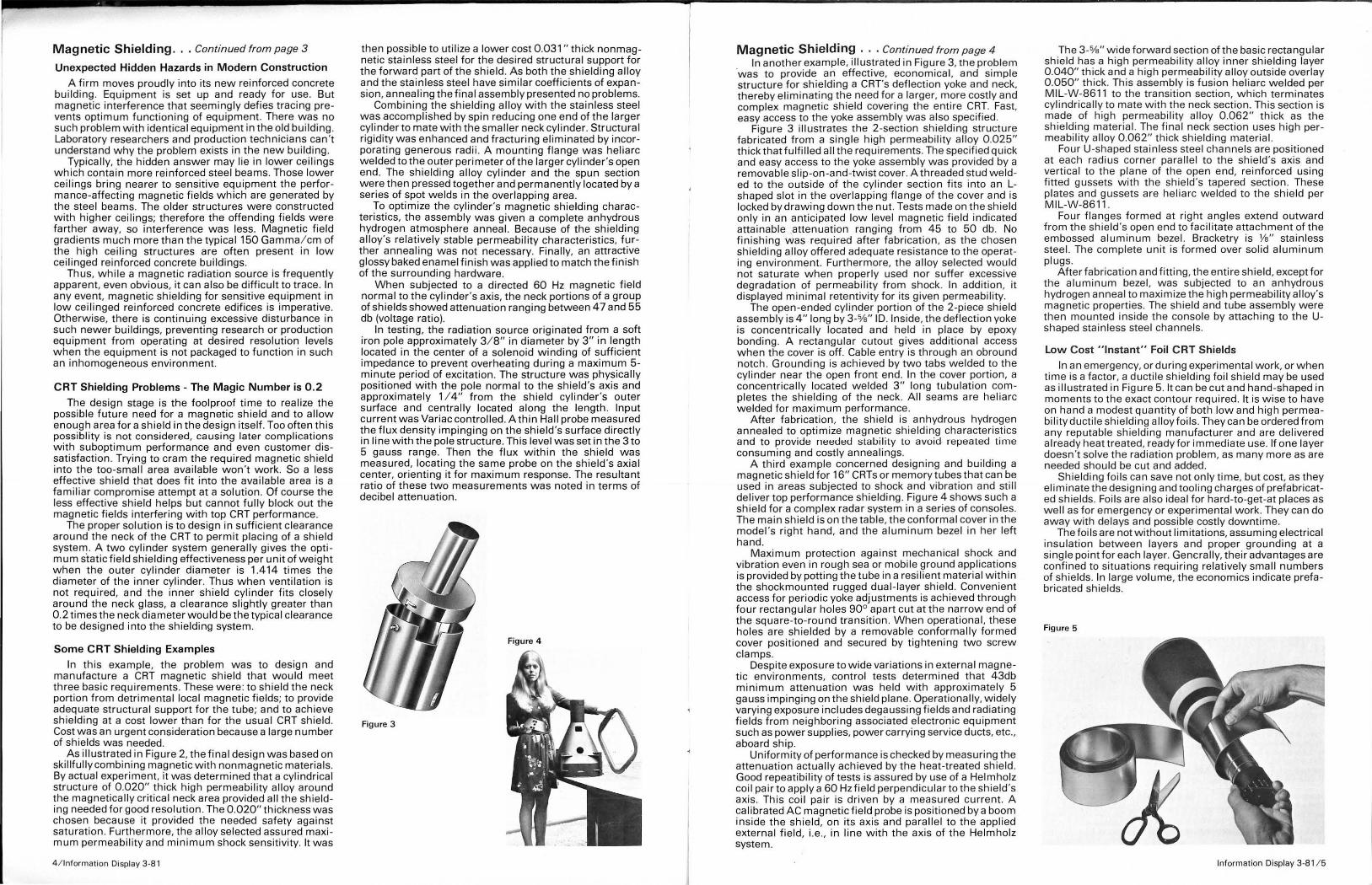
manufacture a CRT magnetic shie ld that wou ld meet three basic requirements. These were: to shield the neck portion from detrimental local magnetic fie lds; to provide adequate structural support for the tube; and to achieve shielding at a cost lower than for the usual CRT shield. Cost was an urgent consideration because a large number of sh ields was needed.
As illustrated in Figure 2, the final design was based on skillfully combining magnetic with nonmagnetic materials. By actual experiment, it was determined that a cylindrical structure of 0.020" thick high permeability alloy around the magnetical ly critica l neck area provided all the shielding needed for good reso lution. The 0.020" thickness was chosen because it provided the needed safety against saturation. Furthermore, the alloy se lected assured maximum permeability and minimum shock sensitivity. It was
4 / lnformation Display 3-8 1
then possible to utilize a lower cost 0.031" thick nonmagnetic stainless steel for the desired structural support for the forward part of the shield. As both the shielding alloy and the stainless steel have similar coefficients of expansion, annealing the final assembly presented no problems.
Combining the shielding alloy with the stainless steel was accomplished by spin reducing one end of the larger cylinder to mate w ith the smaller neck cylinder. Structural rigidity was enhanced and fracturing eliminated by incorporating generous radii. A mounting flange was hel iarc welded to the outer perimeter of the larger cyl inder 's open end. The shielding alloy cylinder and the spun section were then pressed together and permanently located by a series of spot welds in the overlapping area.
To optimize the cylinder's magnetic shielding characteristics, the assembly was given a complete anhydrous hydrogen atmosphere anneal. Because of the shielding alloy's relatively stable permeability characteristics, further annealing was not necessary. Finally, an attractive glossy baked enamel finish was applied to match the finish of the surrounding hardware.
When subjected to a directed 60 Hz magnetic field normal to the cylinder's axis, the neck portions of a group of shields showed attenuation ranging between 47 and 55 db (voltage ratio).
In testing, the radiat ion source originated from a soft iron pole approximately 3/ 8" in diameter by 3" in length located in the center of a solenoid winding of suff icient impedance to prevent overheating during a maximum 5-minute period of excitation. The structure was physically positioned w ith the pole normal to the shield's axis and approximately 1 I 4" from the shield cylinder's outer surface and centrally located along the length. Input current was Variac controlled. A thin Hall probe measured the flux density imping ing on the shield's surface di rectly in line w ith the pole structure. This level was set in the 3 to 5 gauss range. Then the flux within the shield was measured, locating the same probe on the shield's axial center, orienting it for maximum response. The resultant ratio of these two measurements was noted in terms of decibel attenuation.
Figure 4
Figure 3
Magnetic Shielding ... Continued from page 4 In another example, illustrated in Figure 3, the problem
'was to provide an effective, economical. and simple structure for shielding a CRT's deflect ion yoke and neck, thereby eliminating the need for a larger, more costly and complex magnetic shield covering the entire CRT. Fast, easy access to the yoke assembly was also specif ied.
Figure 3 illustrates the 2-section shielding structure fabricated from a single high permeability alloy 0 .025" thick that fulfilled all the requ irements. The specif ied qu ick and easy access to the yoke assembly was provided by a removable sl ip-on-and-twist cover. A threaded stud welded to the outside of the cylinder section f its into an Lshaped slot in the overlapping flange of the cover and is locked by drawing down the nut. Tests made on the shield only in an anticipated low level magnetic field indicated attainable attenuation ra nging from 45 to 50 db. No f inishing was required after fabrication, as the chosen shielding alloy offered adequate resistance to the operating environment. Furthermore, the alloy selected would not saturate when properly used nor suffer excessive degradation of permeabil ity from shock. In addition, it displayed minimal retentivity for its given permeabil ity.
The open-ended cylinder portion of the 2-piece shield assembly is 4" long by 3-o/s" 10. Inside, the deflection yoke is concentrica l ly located and he ld in place by epoxy bonding. A rectangular cutout gives additional access when the cover is off. Cable entry is through an obround notch. Grounding is achieved by two tabs welded to the cylinder near the open front end. In the cover portion, a concentrica l ly located welded 3" long tubulation completes the shielding of the neck. All seams are hel iarc welded for maximum performance.
After fabrication. the shield is anhydrous hydrogen annealed to optimize magnetic shielding characteristics and to provide needed stability to avoid repeated time consuming and costly annealings.
A third example concerned designing and building a magnetic shield for 16" CATs or memory tubes that can be used in areas subjected to shock and vibration and still deliver top performance shielding. Figure 4 shows such a shield for a complex radar system in a series of consoles. The main shield is on the table, the conformal cover in the model's right hand, and the aluminum bezel in her left hand.
Maximum protection against mechanical shock and vibration even in rough sea or mobile ground applications is provided by potting the tube in a resi lient material w ith in the shockmounted rugged dua l- layer sh ield. Convenient access for period ic yoke adjustments is achieved through four rectangular holes 90° apart cut at the narrow end of the square-to-round transition . When operationa l, these holes are shielded by a removable conformally formed cover positioned and secured by tightening two screw clamps.
Despite exposure to wide variations in external magnetic environments, control tests determined that 43db minimum attenuation was held with approximately 5 gauss impinging on the shield plane. Operationally, w idely varying exposure includes degaussing f ields and radiating fields from neighboring associated electronic equipment such as power supplies, power carrying service ducts, etc., aboard ship.
Uniformity of performance is checked by measuring the attenuation actua lly achieved by the heat-treated shield. Good repeatibi l ity of tests is assured by use of a Helmholz coi l pai r to apply a 60Hz field perpendicular to the shie ld 's axis. This coil pair is driven by a measured current. A calibrated AC magnetic field probe is positioned by a boom inside the shield, on its axis and parallel to t he applied external field, i. e., in line with the axis of the Helmholz system.
The 3-o/s" wide forward section of the basic rectangular sh ield has a high permeability alloy inner sh ielding layer 0.040" th ick and a high permeability alloy outside overlay 0.050" th ick. Th is assembly is fusion heliarc welded per M IL-W-8611 to the transition section, which terminates cyl indrically to mate w ith the neck section. This section is made of h igh permeability alloy 0 .062" th ick as the shielding material. The f inal neck section uses high permeability alloy 0 .062" thick shielding material.
Four U-shaped sta inless steel channels are posit ioned at each radius corner parallel to the shield 's axis and vert ica l to the plane of the open end, reinforced using fitted gussets w ith the sh ield 's tapered section . These plates and gussets are helia rc welded to the shield per MIL-W-8611 .
Four f langes formed at right angles extend outward from the sh ield 's open end to faci l itate attachment of the embossed aluminum bezel. Bracketry is Ya" stainless steel. The complete unit is formed over solid aluminum plugs.
After fabrication and fitting, the entire shield, except for the aluminum bezel , was subjected to an anhydrous hydrogen annea l to maximize the high permeabi lity alloy's magnetic properties . The shield and tube assembly were then mounted inside t he console by attaching to the Ushaped stainless steel channels.
low Cost "Instant" Foil CRT Shields
In an emergency, or during experimental work, or when time is a factor, a ductile shielding foil shield may be used as illustrated in Figure 5. It can be cut and hand-shaped in moments to the exact contour requ ired. It is w ise to have on hand a modest quantity of both low and high permeability ductile shielding alloy foi ls. They can be ordered from any reputable shielding manufacturer and are del ivered already heat treated, ready for immediate use. If one layer doesn 't solve the rad iation problem, as many more as are needed should be cut and added.
Shielding foils can save not only time. but cost, as they eliminate the designing and tooling charges of prefabricated shields. Foils are also ideal for hard-to-get-at places as well as for emergency or experimental work. They can do away with delays and possible costly downtime.
The foils are not without lim itations, assuming electrical insu lation between layers and proper grounding at a sing le point for each layer. Generally, their advantages are confined to situations requiring relatively small numbers of shields. In large volume, the economics indicate prefabricated shields.
Figure 5
Information Display 3 -8 1/ 5

t GREETINGS TO NEW SID MEMBERS! Each month you'll find a roster of new SID Members, listed by Chapters with the Chapters in alphabetical order. If your name- or a friend's- should have been listed and was inadvertently omitted, please let June Friend or your Editor know immediately. We'll make amends in the next issue. See the front cover for your choice of addresses to which to send vita l data.
BAY AREA CHAPTER Bernard, Thomas J . AM-BA Vice President A. N.D., Div of W. J. Purdy Co., 770 Airport Blvd., Burlingame, CA 94010 (415) 347-9916 Ext. 247
Browne, John C. M-SU-BA 9401 S.W. Washington St., Portland, OR 97225 (503) 292-5651 Gen'l Mgr., Terminals & Displays Bus. Unit Tektronix, Inc., PO Box 500 63-659, Beaverton, OR 97005 (503) 685-3121
Infante, Carlo M -SU-BA IDD Technology Director Tektronix, Inc. PO Box 500, Beaverton, OR 97077 (503) 685-3453
Preiss, Richard B. M-SU-BA 14125 SW Wilson Drive .• Beaverton, Oregon 97005 (503) 646-9424 Engineering Manager Tektronix, Inc. PO Box 500 63-659, Beaver OR 97005 (503) 685-3647
Silzars, Aris M-SU-BA Director of Solid State Group Tektronix, Inc. PO Box 500, 504 79, Beaverton, OR 97077 (503)644-0161 Ext. 69 11
DELAWARE VALLEY CHAPTER Bauer, James E. M-SU-DV 2334 Triebel Rd., Roslyn, PA 19001 (215) 887-1434 V.P. Inti' Sa les Aydin Controls 414 Commerce Dr .• Fort Washington, PA 19034 (215) 542-7800
Vara, Alfred M M-SU-DV 1807 Mare Road, Warrington PA 18976 (215) 343-9155 Vice President Aydin Controls 414 Commerce Drive, Ft. Washington, PA 19034 (215) 542-7800
EUROPEAN CHAPTER Bonye, Gordon R M -SU-EUR General Manager Rank Electronic Tubes Sidcup By-Pass, Sidcup Kent, England DA 14 6L.Z 01-302 072 Ext. 32
Fryer, Stuart J M -SU-EUR Marketing Manger Rank Electronic Tubes Sidcup By-Pass, Sidcup Kent, England, DA 14 69Z 01 302-0271 Ext. 36
Goodwin, Ronald K. M-SU-EUR Works Manager Rank Electronic Tubes Sidcup By-Pass Sidcup Kent, EnglandDA 14 6L.Z 01 302-0271 Ext 7
6/ lnformation Display 3-81
Hills, Douglas S M-SU-EUR Engineering Consultant Rank Electronic Tubes Sidcup By-Pass Sidcup Kent, England 01 302-0271 Ext. 33
Johnson, Ronald G M -SU-EUR R & D Manager Rank Electronic Tubes Sidcup By-Pass Sidcup Kent, England DA 14 6 Lz 01 302-0271 Ext. 2
Piller, Ernest M M-EUR Meidlinger Hpt Str. 7/ 3/ 13 Vienna Austria A-1120 0222 852-3003 Assistant Professor Technische Universitat Gushhausstr. 27, Vienna Austra A-1040 0222 653785-788
Sjoekvist, Goesta M-EUR Skarpangsvagen 8 18341 Taby 08 758-4682 Systems Manager SRA Communications AB Box 1 16300 spanga, Stockholm, Sweden 08 752-1000 Ext. 1467
JAPAN CHAPTER Michio, Yoshizawa M-JP 738-31 Hata-Mati Chiba-City, Japan 281 0472 - 72 - 9341
Technical Division RICOH Company, LTD. 3-6, 1-chome, Naka-magome, Ohtaku, Tokyo, Japan 143 03- 777 - 8111 Ext. 2781
Tsuemnari, Saito M-JP 6-17-35 Chiuoh Ohta-ku, Tokyo, Japan 143 (03) 753-6155 Engineer Sony Corporation (Osaki Plant) 10-14 Osaki-Z chome Shinagawa-Ku, Tokyo, Japan 141 (03) 493-3406
LOS ANGELES CHAPTER Cronin, Paul V M-LA 22912 Rumble OR., El Toro, CA 92630 (714) 501 -0306 V.P. Display Division Symbolic Displays Inc. 1762 MeGan, Irvine, CA 92714 (714) 546-0601
Gradin, James H M -SU-LA 5042 Paseo Dali, Irvine CA 92715 (714) 851-0135 Vice President Engr. Trans Com 3100 Pullman. Costa Mesa, CA 92626 (714) 979-2600 Ext. 50
J oseph, John S. M-SU-LA 11902 Reagan St., Los Alamitos. CA. 90720 (213) 598-2895 Section Mgr. Electrical Engr. Transcom 160 McCormick St. , Costa Mesa Ca. 92626 (714) 979-2600 Ext. 76
Kushner, Doreen C. M-LA 2211 E. 19th St., Signal Hill, CA 90806 (213)433-8419 User / System Interface Engineer- Xerox Corp. 701 S. Aviation Blvd. A 1-66, El Segundo, CA 90245 (213) 536-9302
Parsons, Thomas T M-LA 1349 E. La Pa lma Ave., Anaheim, Ca 92805 (714) 956-7413 Mfg. Eng Symbolic Displays Inc. 1762 McGaw, Irvine, CA 92714 (714) 546-0601
Webber, Lonnie D M-SU-LA 9388 Grackle Ave., Fountain Val., CA 92708 (714) 962-2612 Manager, Applications Engineering TRANS COM 3100 Pullman St., Costa Mesa. CA 92626
MID-ATLANTIC CHAPTER Beasty, Michael L. Jr. M-SU-MA Vice President Thomas Electronics, Inc. 101 Riverview Drive, Wayne, NJ 07470 (201) 696s-5200 Ext. 57
Cole, John, A M-SU-MA 38 Kenwood Rd., Garden City, NY 11530 (516) 742-2477 Principa l Engineer Hartman Systems Co. 360 Wolf Hill Rd., Dept. 50, Huntington Sta., NY 11746 (5 16) 427-7500 Ext. 221
Kelley, Everett J . M-SU-MA 11 Radburn Drive, Commack NY 11725 (516) 864-3997 Research Engineer Hartman Systems 360 Wolf Hil l Road Huntington Sta., NY 11746 (516) 427-7500 Ext. 226
Ketchum, Harold A M -SU-MA Box 686, Bernardsville, NJ 07924 (201) 543-495 1 Chairman of Board Thomas Electronics Inc. 100 Riverview Dr. Wayne, NJ 07470 (201) 696-5200
Kinoshita, Kazuya M-MA 345, 7th St. #E, Palisades Park, NJ 07650 (201) 947-4136 41 Madison Ave., New York, NY 10010 (212) 481 -3440
Lowney, Daniel F M-SU-MA 282 Rockaway St., Islip Terrace, NY 11752 (516) 277-3568 Systems Section Head Display Hartman Systems Div. ATO 360 Wolf Hill Rd. Huntington Station, NY 11746 (516) 427-7500 Ext. 222
Miner, Carla J M-MA Member Technological Staff Bell Northern Research P.O. Box 3511 Station C, Ottawa, Ontario CANADA K1Y4H7 (613) 596-6285
New Members .. . Continued from page 6
· McMullen, Andres M-SU-MA 8Nor3wood Road, Northport, NY 11768 (516) 757-0389 Principal Engineer Hartman systems Div. of ATO 360 Wolf Hi ll Rd. Huntington Station, NY 11746 (516) 427-7500 Ext. 221
Piaget, Bruce A M-SU-MA 100 Riverview Drive, Wayne, NJ 07470 (201) 838-74 70 Sales Engineer Thomas Electronics, Inc. 100 Riverview Drive Wayne, NJ 07470 (201) 696-5200
Schwartz, Harold H M-SU-MA 28 Seventh Street, Bayville, NY 11709 (516) 628-2815 SR. Elect. Eng. Hartman Systems 360 Wolf Hill Road, Huntington Station, NY 11746 (516) 427-7500 Ext. 223 Seats, Peter M-SU-MA President Thomas Electronics Inc. 100 Riverview Drive Wayne, NJ 07470 (201) 696-5200
Setticase, Ben M -SU-MA V. P. Marketing Thomas Electronics, Inc. 100 Riverview Drive Wayne, NJ 07470 (201) 696-5200
Suga, Hikotsugu 393 Oak St., Ridgefield NJ 07657 (20 1) 943-3477
MIDWEST CHAPTER
M-MA
Brown, William K. M-MW 4926 lvybrook Drive, Fort Wayne, Indiana 46815(219)485-9269
*Senior Staff Engineer Magnavox, 1010 Production Rd., Dept. 528 Fort Wayne, Indiana 46808 (219) 429-5598
Myers. Joseph T. (II) M-MW 830 Bryce Road, Kent, OH 44240 (216) 673-3936
*Managing Partner/General Manager Nypano Company, 765 Stow St., P.O. Box 753 Kent, Ohio 44240 (216) 673-4914
Ward, Sharon L. M-MW 5585 S. Dayton Brandt Rd., New Carlisle Ohio 45344 (51 3) 845-1256 '
*Operation Research Analyst AF Aerospace MED Research LAB/ HEC Wright-Patterson AFB, Ohio45433 (513) 255-3438
NEW ENGLAND CHAPTER Aubin, Richard E. M-NE
*268 Temple St., West Roxbury, MA 02132 (617) 327-8538 Vice President Geo. D. Sandel Assoc .• 479 Winter St. Waltham, MA 02154 (617) 890-0713
Death, Morgan E. SU-NE 9 Beckley St., Nashua, NH 03050 (603) 883-6974
*Marketing Manager, Govt. Systems Sanders Assoc. Inc., Daniel Webster Highway, South Nashua. NH 03061 (603) 885-3522
lannotta, Ben C. M-SU-NE 172 Red Acre Rd., Stow, MA 01775 (617) 897-9169
*V.P. Marketing Display Components, Inc., 334 Littleton Rd ., Westford, MA 01886 (617) 692-6000
Klein, Stanley M-NE *39 HnrnP.ss Lane. Sudbury, MA 01776 (617) 443-3458 Publisher Harvard Newsletter on Computer Graphics, 730 Boston Post Rd., Sudbury, MA 01776 (617) 443-4671
TAB Products Markets Smart Terminal
TAB Products Co., Palo Alto, CA, has introduced a new editing CRT display term inal, t he TAB 132/ 15. Developed by the company's electronic office products group, t his terminal features a 15-inch, non-glare, high resolution screen, 80 or 132 column format, 7 x 11 dot matr ix characters in a 9 x 14 or 9 x 16 cell , screen-labeled soft keys, and English language prompts for set up and operation modes.
" One of the strongest fea tures," says Robert J. Stroh, electronic office products director of marketing, " is the eight soft keys. These keys put over 100 funct ions, some of which are user programmable, at the operator's fingertips.
Macintyre, Alfred J. M-NE P.O. Box 46, Nashua, NH 03060 (603) 882-8997
*Component Engineer Fasfax Corp., Simon & Ledge St., Nashua. NH 03060 (603) 889-5152 Ext. 27
Sawyer, Carleton E. M -SU-NE 557 Newtown Rd., Littleton, MA 01460 (617) 486-4 788
*President Display Components, Inc .. 334 Littleton Rd., Westford, MA 01886 (617) 692-6000
SAN DIEGO CHAPTER Archuleta. William P. M-SU-SD
*667 Marsolan, Solana Beach, CA 92075 (714) 755-2380 Product Dev. Manager, Displays SAl Technology Company, A Division of Science Applications. Inc., 4060 Sorrento Valley Boulevard. San Diego, CA 92121 (714) 452-9150 Ext. 241
Highstrete, Bruce A . M-SU-SD P.O. Box 9, Bonsall, CA 92003 (714) 758-0947
*Division Manager Hughes A ircraft Company, 6155 El Camino Real, Carlsbad, CA 92008 (71 4) 438-9191 Ext. 400
SOUTHWEST CHAPTER Williams. Rodney Don M -SW
*P.O. Box 91 16, College Station, TX 77840 (71 3) 693-995 7 Research Associate Texas A&M University College Station, TX 77840 (713) 845-2736
"The TAB 132/ 15," Stroh says, "is designed specifically tor the operator. English (or other) language prompts lead the operator through set up and operation modes. There is no need to learn 'computerese' or to refer to deta iled manual instructions.
The TAl 132/15 irurt lft sp l•'J fer•ll'lll f u tures 1 15 - l t~ch , h i gh resolut t oft , no•-gla re sc reel'l , wl t h 10 or UZ colu•ll f orut. l a rt• . f l lc;t l!'r-fr l!e ch• r uhrs •re for•ed by
" Features such as bidirectional smooth or j ump scroll, horizonta l scroll, split screen, communications speeds to 19,200 baud, four pages of display memory, a ful ly displayed status line, make the TAB 132/ 15 suited to almost any application.
"To our knowledge," claims Stroh, "t he TAB 132/ 15 is the first fu l ly featured smart term inal on the market in its price range."
1 7 x II dot • • tr h Ia 1 9 a U or 9 x 16 cel l. Ch.r1chr • ttrlbutu hclude blhlktng , bo ld . und1rl tne , re·nrst •Ideo. Prolecled fie lds r~:y be based on ~: ny 1ttr t bule.
The TAB 132/ 15 smart display terminal features a 15-inch, high resolution, non-g lare screen, w ith 80 or 132 column format. Large, flicker-free characters are formed by a 7 x 11 dot matrix in a 9 x 14 or 9 x 16 cell. Character attributes include blinking, bold, underline, reverse video. Protected fields may be based on any attribute.
In addition to marketing the terminal directly through the TAB sa les offices, the company w ill sell t hrough distributors, orig inal equipment manufacturers, and systems houses.
Information Display 3-81 / 7

Takes outo
ectral analysis the back room.
The Pritchard® Model1980B Spectroradiometer puts it on the production line.
It offers simple, error-free, computer assisted spectroradiometric scanning.
The Pritchard PRTM 1980B Scanning Spectroradiometric System is a completely integrated spectral scanning system featuring operating procedures that can be quickly learned by even inexperienced personnel.
The HP Computer/Controller that is part of the system has been tailored to meet your needs. Software programs have been specially written to minimize program initiation procedures, often down to a single keystroke command.
For visible spectral analysis of color integrity and color matching, for accuracy and repeatability, for the special signature of a display that is its "fingerprint" of color output, the PR 1980B System has no equal.
And for your added convenience, a single control instantly converts the PR 1980B into a standard PR 1980A photometer.
Let us help you take the complexity out of computer assisted spectroradiometric scanning. Call or write for complete information. Photo Research Division of Kollmorgen Corporation 3000 No. Hollywood Way Burbank, CA 91505 (213) 843-6100
PHOTO RESEARCH™ The Light Measurement People
Circle No. 13
1981
April 1
6
20
20
27
April 27
May 1
July 1
20
September 16-18
1981
March 23-24
24-27
May 4-7
4-7
June 17-19
18
24-26
August 17-22
24-28
26-29
November 1-4
SID CALENDAR MARCH TO SEPTEMBER 1981
Proceedings, Volume 22, No. 2, 1981, Mailed
National Ballot Return Deadline
Quarterly Mailed
Executive Committee Meeting
National Board Meeting, New York, NY
SID 1981 Internationa l Symposium
Grand Hyatt Hotel, New York, NY
Proceedings, Volume 22, No. 3, 1981, Mailed
Quarterly Chapter Rebates Mailed
Eurodisplay 81 - The First European Display Research
Munich, Germany
OTHER EVENTS
Office Automation Conference, Houston, TX
Printemps lnformatique (DEP exhibition), Paris, France
National Computer Conference, Chicago, IL
Personal Computing Festival, Chicago, IL
Conference,
International Conference on Optical Radiation Measurements of Fluorescent
and Retroflective Materials, Minneapolis, MN
20th Annual ACM Symposium (NBS and ACM), College Park, MD
Computer Industry Trade Expo, Atlantic City, NJ
5th Internationa l Congress of Cybernetics and Systems, Mexico City
SPIE Annual International Technical Symposium & Exhibit, San Diego, CA
National Small Computer Show, New York, NY
DPMA's 30th International Conference & Business Exposition, San
Francisco, CA
Information Display 3-8 1 /9

Call For Nominations Of Candidates For The 1982 SID Honors And Awards
The SID Honors and Awards Committee is soliciting your help in nominating qualified candidates for Fellow, for the Frances Rice Darne Memorial Award, and for Special Recognition Awards. General qualifications based on the SID Bylaw requirements for honors and awards are given below.
(1) FELLOW
The grade of Fellow is one of unusual professional distinction conferred by the Board of Directors, acting on the recommendation of the Honors and Awards Committee, upon a SID member of outstanding qualifications and exper ience as a scientist or engineer in the field of Information Display. The candidate shall have made a widely recognized and significant contribution to the advancement of the field. The nomination must be supported and signed by at least five members in good standing.
1982 Guidelines For SID Honors And Awards Nominations
Nominations for SID Honors and Awards should be concise, but they must inc lude the following information, preferably in the order given below.
(1) Name, Present Occupation, Business and Home Address, and SID Membership Grade (Member or Fellow) of Nominee.
(2) Award being recommended: (a) Fellow*, (b) Francis Rice Darne Memorial Award, (c) Special Recongition . * Fellow nominations must be supported and signed by at least five SID members.
(3) Proposed Citation - this should not exceed thirty words.
(4) Name, Address, Telephone Number, and SID Membership Grade of Nominator.
(5) Education and Professiona l History of CandidateInclude college and/ or university degrees, positions and responsibilit ies of each professional employment.
(6) Professional Awards and Other Professiona l Society Affiliations and Grades of Membership.
1 0/lnformation Display 3-81
(2) FRANCES RICE DARNE MEMORIAL AWARD
The Frances Rice Darne Memorial Award is awarded periodica lly, but not more than once each year, to a Society member for an outstanding technical achievement (as opposed to teaching, publication, or service) in, or contribution to, the display field. The award is made by the Board of Directors acting on the recommendation of the Honors and Awards Committee.
(3) SPECIAL RECOGNITION AWARDS
Special citation awards are given to members of the technical and scientific community, not necessarily SID members, for distinguished and valued contributions to the Information Display field. These awards may be made for contributions in one or more of the following categories:
a. Outstanding technical accomplishments. b. Outstanding contributions to the literature. c. Outstanding service to the Society.
Nominations should comply with the 1982 Guidelines for SID Honors and Awards Nominations, and they should be submitted to the Honors and Awards Committee Cha irman at any time during the year, but no later than June 30, 1981.
(7) Specific statement by the nominator concerning the most significant achievement or achievements or outstanding technical leadership which qualifies the candidate for the award. This is the most important consideration for the awards committee, and it should be specific (citing references when necessary) and concise.
(8) Supportive material: Cite specific evidence such as patents, publications, SID activities, other technical and/ or professional society activities, evidence of outstanding leadership, etc. Please be specific and concise. Cite material that directly supports the citation and statement in (7) above. Limit the evidence to the most important patents, publications, or service- do not generalize.
(9) References: Fellow nomination must be supported by the references indicated in (2) above. Supportive letters of reference will strengthen the nomination for any award.
Send the complete nomination- including all the above material-to the Honors and Awards Chairman by June 30, 1981 .
I. Reingold, Chairman SID Honors and Awards Committee USA Electronics Technology & Devices Laboratory, ERADCOM
DELET-B For-Monmouth, NJ 07703 Phone: 201-544-5740
-~ --
Intelligent Copier Using Liquid Crystal Dot Matrix Imaging
For Printing
Show n here from Static Systems Corporat ion, New York City, is a photograph of the first liquid crysta l printing intelligent copier. Any RS232 pi ug serial or parallel display computer type or word processing terminal may be plugged into the copier up to a maximum of 16 un its with collator. The copier shown is t he EP310 self-diagnostic electronic copier made by M inolta. This has a Static Systems Corporation liquid crystal imager made by Hitachi, with upper-lower case single-l ine page w idth display of 80 characters. The mounted imager display box on the copier where the cover would normally be also contains a strobe unit flashed every tenth of a second and synchronized to the speed of the liquid crystal display, which is 100 milliseconds. This is equa l to 10 lines per second or four to five seconds for the average page.
According to SID member Bob Lester, president of Static Systems corporat ion , the liquid crystal speed is synchronized to the drum speed of t he copier. The purpose of the strobe light is to illuminate the liquid crystal matrix display prior to the change, preventing any blur such as would occur if a cont inuous light source were left on between changes due to the slowness of the display. However, direct-driven dot matrix liquid crystals of high speed (less than one millisecond on-off) w ill be available later this year, eliminating the strobe light and allowing the use of the fastest copy machines ava ilable.
Looking ahead to the next few years, the inventor expects that full screen (page size) for graphic quality al lowing any style of font will be available for imaging, eliminating the scroll ing of the single line alphanumeric dot matrix LCD.
Liquid crystal imaging provides solid state graph ics at very low cost and w ith exceptionally low power requirements. Liquid crysta l image printing is another new method to be added to the list, such as lasers, fiber optics, thermal, inkjet, electrostatic and all types of impact printers, with advantages over all of the above, says Lester.
Chomerics Offers Lifetime Keyboard Guarantee
Chomerics, Inc. Woburn, MA, a major membrane keyboard manufacturer, recently announced it w i ll offer lifetime guarantees on its Fastype™ line of alphanumeric keyboards. The guarantee covers end-product keyboard use, and is said to be the fi rst available in the A / N keyboard market.
In making the announcement, Len Halio, genera l manager of Chomerics alphanumeric products said: " Issuance of a lifetime guarantee reflects t he qual ity and re liabil ity of our Fastype keyboards. Since we have complete control over the manufact ur ing process-from condu'::i've ink form ulation to keytop product ion-it is only natural that we stand behind our products.
" Furthermore, Chomerics is in the un ique posit ion of being the world leader in membrane switch technology. The company invented this technology in t he late '60s and holds more than 100 patents covering the spectrum of material and component developments critical to its reliability and economy," sa id Halio.
In outlining the guarantee progra m, Chomerics stated that it wi ll unconditionally replace any keyboard that becomes defective in the course of normal operation in end-use applications . Halio said," This does not cover damage resulting from abuse. It is effective w ith shipments on or after January 1, 1981."
Chomerics, w ith nearly half of the membrane keyboard market, introduced a complete line of high-end, alphanumeric membrane keyboards last year. Membrane switches are said to provide a cost-effective alternat ive to both conventional electromechanica l and solid state switchbased keyboard designs.
Halio points out that Chomerics has del ivered ,more than 15 mill ion membrane keyboards for over 1,000 applications since 1970. Its keyboards are currently integrated into products such as a computerized PABX system, an industrial robot, applicances, telephones, electronic toys, instruments, and terminals.
Lifetime guarantee now offered on Fastype1 M line of alphanumeric membrane keyboards from Chomerics Inc.
Information Display 3-81 / 11

HIGHLIGHTS OF THE SID '81 INTERNATIONAL SEMINAR AND SYMPOSIUM
Symposium Topics Covered in 16 Daytime Sessions:
Electroluminscent Displays Hard Copy Human Factors Non-Impact Printing and Recording Passive Displays Color CRTs CRTs Panel and Large Screen Displays Graphics and Image Processing Plasma Displays Display Systems
Seminar Topics Covered in Two Day Sessions (April 27 and May 1)
CRTs for Information Display Passive Displays AC Plasma Display Panel Fabrication Technology and
Intrinsic Panel Addressing Techniques Electroluminescent Displays Printer Technology and Applications Display Interface Requirements Architecture for Display Terminals Human Factors and Display Quality Display Technology Forecasting
Keynote Address:
Videotext: Information Display for the Mass Market, by Richard Clark, Joan de Smith (Systems) Ltd., London, England.
Progress report on display standards, stytem designs, prospects for the future.
Invited Papers:
Telconferencing for Business Meetings Space Industria lization and the Role of Information Display Hardcopy Technology in Japan Trends in AC Plasma Displays in Japan
Luncheon Address:
Sports telecast programming by the NBC sports director. His talk will cover setup procedures and a wide assortment of display equipment required, illustrated by video tapes.
Evening Panel Topics:
Displays and Health Hazards IC Approaches to Addressing Problems Engineering/ Scientific Office of the Future.
Number of Authors/ Coauthors:
More than 175 from U.S., Eng land, Finland, France, Japan, Switzerland, Taiwan, and West Germany.
12/ lnformation Display 3 -81
Award Ceremonies:
198o Symposium Best Papers Sid Honors and Awards
Exhibition:
International show featuring latest developments in equipment. accessories, components, and measuring devices.
Symposium Registration Fees:
Advance . .. $50.00 (Member) ... $65.00 (Nonmember) Symnposium ... $60.00 (Member) ... $75.00 (Nonmem-ber
Seminar Registration Fees:
One Day (Monday or Friday) ... $80.00 Two Days (Monday and Friday) ... $125.00
DIGESTs (Additional Copies):
$30.00 (Member) ... $40.00 (Nonmember)
Symposium/ Seminar/ Exhibit Dates:
Symposium and Exhibition .. . Tuesday to Thursday, April
~:~i~ars: Monday, April. 27 and Friday, May 1
Symposium/ Seminar / Exhibit Information:
Lewis Winner, 301 Almeria / Box 343788, Coral Gables, FL 33134. 305-446-8193/ 4(1 :00-5:00 P.M.)
G) N
l;, < ,;..
i "' 1-
0 l'l
4:00P.M. 9:00P.M.
8 :00A.M. 8:30A.M.
8:30A.M. 5 :15P.M.
5:00P.M. 9 :00P.M.
8:00A.M. 4 :00P.M.
10:00 A.M. 5:30P.M.
9:00A.M. 9:30A.M.
9:30A.M. 10: 15 A.M.
10: 15 A.M. 11 :00 A .M.
11 :00 A .M. 12:00 Noon
12:05 P.M. 1:40P.M. [Lunch)
2:00P.M. 5:00P.M.
5 : 15P.M. 6:15P.M . 6 :00P.M. 7 :30P.M.
8:00P.M.
Empire State Ballroom Foyer
Sl D 81 Registration
Seminar Registration
Sl D 81 Registration
Sl D 81 Registration
8 :00A.M. SID 81 Registration 4:00P.M.
9 :00A.M . 5:00P.M.
9 :00A.M. 11 :45 A.M.
12 :00 Noon 1:50P.M. [ Lunch)
2 :15P.M. 5:00 P.M.
5: 15P.M. 6 : 15P.M.
8:00P.M.
8 ' 00 A .M. SID 81 Registration 11 :00A.M.
9 :00A.M. 12:00 Noon
l;, 9 :00A.M. < 12:00 Noon
~ ... '1:)> ·-. . .t :E
12:00 Noon 1:00 P.M.
12:00 Noon 1:40 P.M . [Lunch)
2:00P.M. 5:00P.M .
8 :00A.M. 8:30A.M . 8 :30A.M . 5 :15P.M.
Seminar Registration
SID '81 AT THE GRAND HYATT HOTEL NEW YORK CITY
A B
Exhibits
Social Hour
Exhibits
Exhibits
Empire State Ballrooms
c D
SESSION I Sl D BUSINESS MEETING
SESSION II FORMAL OPENING
SESSION Ill KEYNOTE ADDRESS
SESSION IV INVITED ADDRESSES
SESSION V Electroluminescent
Displays
SESSION VI Hard Copy
AUTHOR INT ERV IEWS
INFORMAL DJSCUSSIONS E-1 E-2
Health Hazards and IC Approaches t o Displays Addressing
SESSION VIII Non-Impact Printing and Recording
Lunch Invited Talk
E-3 E ngineeri ng-Scien t ific Office of the Future
SESSION XIII Panel Displays
SESSION XV Plasma Displays
Problems
SESSION IX Passive
Displays I
SESSION X I Passive
Displays I I
SESSION XIV Image Processing
Graphics
SESSION XVI Display Systems
E
SESSION V II Human Factors
SESSION X Color CATs
SESSION X II CATs
AUTHOR INTERV IEWS
AUTHOR INTERVI EWS
CARNEGIESWAY
JULLIARD
SEMINAR I-IV
SEMINAR V- VIII
Information Display 3-81 / 13
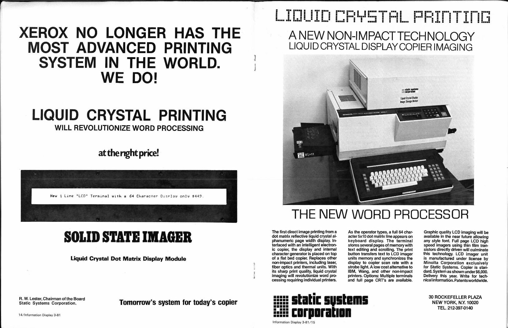
XEROX NO LONGER HAS THE MOST ADVANCED PRINTING
SYSTEM IN THE WORLD. WE DO!
LIQUID CRYSTAL PRINTING WILL REVOLUTIONIZE WORD PROCESSING
at the r.ght price! -
SOLID STATE IMAGER Liquid Crystal Dot Matrix Display Module
R. W. Lester, Chairman ofthe Board Static Systems Corporation.
14 / lnformation Display 3-8 1
Tomorrow's system for today's copier
I ••• ••••• • • ••• •••• • II II Ill I I • • • • • • • • • 11.111111 ••••• ••• ••••• ••• ••• • •••
1•••1 1•••. I I 1•••• ••1•• .•••. I • • • • • • • • • • • •••• ••••• ••••• • ••••• • • • • • • • • • • • • • • • • • • • • ••••• • • • ••••• • • • •••••
••••• •••• ••• •••• ••••• ••• •••• • •••• • • • • • • • • • • • • • • • • • • • • • • • • • ••••• •••• • • • • • • • • • • • • • • • • • • • • • • • • • • • • • • • • • • • • • ••• • • • ••• • • • ••••
A NEW NON-IMPACT TECHNOLOGY LIQUID CRYSTAL DISPLAY COPIER IMAGING
THE NEW WORD PROCESSOR The first direct image printing from a dot matrix reflective liquid crystal al· phanumeric page width display. In· terfaced with an intelligent electron· ic copier, the display and internal character generator is placed on top of a flat bed copier. Replaces other non-impact printers, including laser, fiber optics and thermal units. With its sharp print quality, liquid crystal imaging will revolutionize word processing requiring individual printers.
As the operator types, a full 64 char· acter 5x1 0 dot matrix line appears on keyboard display. The terminal stores several pages of memory with text editing and scrolling. The print button transfers text to LCD imager units memory and synchronizes the display to copier scan rate with a strobe light. A low cost alternative to IBM, Wang, and other non-impact printers. Options: Multiple terminals and full page CRT's are available.
5!!55 stati.: sustams • •••• E:EEE I:DFIIIFitlll Information Display 3-8 1 / 15
Graphic quality LCD imaging will be available in the near future allowing any style font. Full page LCD high speed imagers using thin film tran· sistors directly driven will culminate this technology. LCD imager unit is manufactured under license by Minolta Corporation exclusively for Static Systems. Copier is stan· dard. System as shown under $6,000. Delivery this year. Write for tech· nical information. Patents worldwide.
30 ROCKEFELLER PLAZA NEW YORK, N.Y. 10020
TEL. 212·397·0140

TRW-Fujitsu Introduces New POS Terminal
The TRW-Fujitsu Company (TFC), Los Angeles, recently announced its first product since the joint venture begana retail POS terminal that offers retailers a high degree of flexibility in tai loring terminal operation to specific pointof-sale transaction needs.
The terminal, designated the TFC 7880, makes available a choice of display types, keyboard types, cash drawers and memory configurations including up to one megabyte of internal storage using bubble memory technology. The manufacturer states that this flexibility, combined with proven transaction software, gives the user the ability to configure each terminal with only those features necessary to match his operating style .
"TRW-Fujitsu is offering retailers two highly sophisti cated 'a Ia carte' menus of features and transaction software, " says William Carr, vice president of retail systems. for TFC.
The TFC 7880 offers the user one of three display types, ranging from a numeric version providing basic operator prompting to one that's highly interactive. A 40 character alphanumeric display type provides additional prompting flexibility. Also available is a full function 320 character version utilizing plasma display technology.
"With three choices, you select and pay for the level of operator prompting required to perform transactions best at each particular point of sale," Carr explained. " For checkout lanes where operators perform routine transactions, a numeric display may be all that's needed."
The plasma display offers the highest level of operator prompting and is appropriate where transactions are more complex, such as at customer service desks to handle layaways and returns. An optional customer display is also available.
The system's transaction software works with each of the displays, so operations continuity can be maintained when different display types are used in the same store.
"The powerful microprocessor-based terminal can function as a dedicated unit in a variety of different retail functions such as checkout, layaway, stockroom, or customer service, depending on the customer's selection of hardware options and software options," Carr noted.
Internal program memory is available with capacities from 32 K to 128 K bytes of RAM.
Data storage capabilities can be directly ink:,~ rated into the terminal with the addition of a non-volatile bubble memory. The bubble memory capacity ranges from 32 K to one million bytes of data storage. The high-speed characteristics of the bubble memory enable users to generate promotional item price lookup or local layaway files quickly.
The 7880 is said to be the first POS terminal to offer as an option a magnetic stripe credit card reader that is directly integrated into the terminal. The card reader located just above the keyboard.
The TFC 7880 terminal also offers a choice of two programmable keyboards for sales recording and data entry. Key functions are coordinated with prompting instructions on each of the three displays to speed and simplify transaction processing. To further improve the speed and accuracy of sales and merchandise information entry, automatic reading capabilities such as OCR-A wand readers can be easily added, TFC states.
In terms of communications, the terminal has been designed to meet both on-line and switched network requirements within the retail industry. It can interface with a variety of processors, controllers, and peripherals, and can be intermixed in a common network to satisfy the exact needs of the retailer.
16/ lnformation Display 3-81
The new POS terminal will be supported by the TRW Customer Service Division, a nationwide service organization. "While the TFC 7880 POS Terminal is brand new, it is far f rom an unknown quantity," Carr said. " Fujitsu products are known worldwide for their quality and reliability."
The TRW-Fujitsu Company' s 7880 POS System is said to be the first on the market to offer as options such state-of-the-art technology as bubble memory, plasma display, and an integrated magnetic stripe card reader.
Programmable Electronic Message System
The Z-PEMS (Programmable Electronic Message System) 8001 manufactured by One-Up, Inc., Santa Ana, CA., was chosen for special recognition in the Advertising and Promotion Showcase at the 1981 International Winter Consumer Electronics Show in Las Vegas.
The Z-PEMS 8001 is a new addition to One-Up's product line of LED computerized message systems. This new system features a high intensity display with fourinch characters. Features include: traveling message presentation; scrolling message; flashes and winks; spells on; wipes on; definable graphics and animation; variable width letters; and a combination of any of the presentations.
The system consists of only two components: the display sign and the programmer. They may be detached, while the memory remains stored in the programmer.
(:: 'iiE f;aJ.;:a ·l-1·1~ r:al-~':tf'•1: :. :1,·,1 f." I ':_··.:.:::l . :_J!.[ _•. -~-•fr-. i _·· ~- ...... - _:_:_:. ___ .·:·:·:-· --
Military& Instrumentation
CRT Bulbs
Projection CRT Bulbs
Fiber Optic CRT Bulbs
Monitor & Data Display
CRT Bulbs
lEE Announces New Family Of Alphanumeric LC Ds
The Industrial Products Division of Industrial Electronic Engineers, Inc., (lEE), Van Nuys, CA. has introduced a new line of low-cost alphanumeric liqu id crystal display modules and accessories. The company's new DAYSTAR minimum logic products replace earlier, more expensive devices. The electrical interface, mounting and cutout dimensions are identical on corresponding new and old models. Principal changes include a low-profile package design and modified environmental specifications. Resulting mass production techniques allow price reductions of up to $180.00 per unit depending on model and quantity purchased, according to Carl Doria, national sales manager, lEE.
The new DAYSTAR minimum logicfamilyincludesfour displays, an optional ASCII controller IC, and cables. There are 1x16, 2x16, 1x40 and 2x40 models. All displays are 5x7 + cursor dot matrix devices. Each requires +5VDC at less than 1 mA. The optional CMOS controller IC is said to reduce system development time by providing an ASCII interface, cu rsor control, character generation, timing and refresh functions.
Demands on the host system are minimized as well. This IC supports the current 5x7 + cursor DAYSTAR displays and upcoming 5x11 + cursor dot matrix models. All items are available immediately. DAYSTAR eva luation kits, consisting of a display, cable and the controller IC mounted on an evaluation board, are being offered for a limited time. The pre-assembled evaluation PC board contains all components and controls required to demonstrate each DA YSTAR feature.
SCHOTT recognizes only one standard for CRT glass: the highest! SCHOTT sets the industry pace with the highest standards of precision, health and safety in CRT glass, and in pioneering technology for CRT applications of today and tomorrow. Our latest state-of-the-art developments, special anti-glare surface treatments for CRT displays, demonstrate SCHOTT's technical expertise and leadership. Tell us about your CRT glass design or production requirements. Call or write today.
Visit SCHOTT at S.l.D., Booth 410; N.C. C., Booth 2007
~Ho~SCHOTT
~~~AMERICA 11 East 26th Street, New York, New York 10010 (212) 679-8535
magnetic shielding requires precision
manufacturing Over 20 years of experience in the design,
production, quality control and inspection of magnetic shielding assures precision products
that stand up to the closest check.
FREE-send for our new brochure on magnetic shielding alloys and photomultiplier tube shields.
Whatever your application, let M.R.L. meet your needs.
_ Iff ,,~f)/i~ £RADIATION ~ "~'rA/f/rN ~ LABORATORIES, INC. 92 N. Lively Blvd. • Elk Grove V illage, Illinois 60007 • Area Code (3121437 ·5200
Information Display 3-81 / 17 lj

CUT OFF COMPUTER C ABINET I cu 0
SAW Dual Floppy SAW Disk
Junc tion Junction Box
@ Naked M ini Box Length Pholo- Computer
L Photo- l ength
Phot o- Cells Cells Photo-cells cells Detect or
Ill Detector
and and Quad Sources rl& ~-'"'"'" I
Sources
Card Rack
J o;omotor h r
Diameter I Diameter Scanner I ~H Sca nner Diameter I Scanner Scanner Interface I Ill
Inter face Scanner
1 Scannet'
[ I System Interface
WJ Card Rack L 1. Kicker Serial Se rial 1. Kicker 2. Cht~in Saw Interface Interlace 2. ChainS.. 3. Swing Saw 4. Operator 's
Adaptor Adaptor 3. Swing Saw 4. Operator'• ~ ~ Console I Power Supply Conaole
5. CRT 8 5. CRT Console D Console l .l 6. Encoder LEJ
6. Encoder OuttMd
I ~ OutfHd
Conveyor D CRT Tele-CRT I Conveyor
M onitor printer M onitor
Automated lumber Flowchart- Schematic representation of automated cut off saws at the Port Alberni Sawmill in British Columbia. Diagram shows the electrical cabling for system developed by Uoy Controls, Ltd., also of Vancouver. System is controlled by a NAKED MINI computer from Computer Automation, Irvine, CA.
$54 Million Port Alberni Conversion Streamlines Lumbermill Operations
MacMillan-Bioedel, a leading Canadian forests product company, has converted its turn-of-the -century Port Alberni sawmill in British Columbia into what is said to be Canada's most advanced, automated lumber production facility by installing automated equipment and controls developed by Canadian-based Lloyds Controls Ltd. The computerized equipment installed by Lloyd Controls includes NAKED MINI® computers from Computer Automation, Inc. , Irvine, CA.
More wood per tree, less waste per board, faster production, more overall efficiency per daily operationsthose are a few of the hard fact benefits that are derived from Port Alberni's automated sawmill.
" The Port Alberni mill conversion represents an historical shift in the entire nature of sawmilling operations in Canada," reported Dale Tuckey, systems manager for MacMillan Bloedel in Port Alberni. " For many years the industry has employed and relied upon automated equipment and the computer in its pulp and paper mills; but a prevailing attitude among sawmillers wa s that every log was different and wouldn 't accept automation in the same way that chemicals, sawdust. and standard processes would . The job of a lumber sawmill is to slice logs into usable lumber, not turn pulp into cardboard boxes and stationery-and for a very long time lumbermen felt the computer couldn't help produce 2x4's and ceiling rafters." Technology has come a long way in the last few years. Finally, computers and electronic equipment are durable and reliable enough to withstand the harsh environment of the sawmill. And lumbermen are becoming convinced that computers can perform at more optimum levels of productivity than even the most jaundiced -eyed logassessor.
W arren Thomlinson, president at Lloyd Controls, explained just what his company does: " We develop customized systems for sawmills. Our systems can actually analyze every log and determine the best way to cut th e log for maximum product yield and minimum waste. We also provide systems that sort finished lumber product and provide management reports, enabling the sawmill 's
18/ lnformation Display 3-8 1
management to analyze the entire milling operation and productivity on a day-to-day, shift-by-shift basis. "
The Port Alberni sawmill has a total fo five different computer-controlled automated systems that streamline the entire process of producing lumber. Four of those systems were developed by Lloyd Controls Ltd. and rely on NAKED MINI computers from Computer Automation, Inc. The fifth system was supplied by Applied Theory Associates and is controlled by a Hewlett Packard computer.
After a tree has been chopped down and transported to the mill with hundreds of other trees just like it. then the bark is stripped from each log. Debarked trees are ready to move through the mill on a system of conveyors.
Computers throughout the mill have been programmed and contain all the vital information about the logsspecies, marketing requirements, etc. In addition, the computers contain all the programming required to control equipment throughout the mill- saws, conveyors, photooptic cells, etc.
Information such as the dollar value of different cuts and sizes of lumber, demand for each kind of board, and the overall profitability obtainable from the lumber is stored inside the computers. The computers are prepared to tell mill operators whether 2x4's, 2x6's, joists, rafters, or other cuts of lumber are preferable. In some instances the computer automatically relays that information to automatic saws that can slice logs without an operator.
Logs move into the mill on conveyors. Each log is scanned by photo-optic cells which measure the log for diameter and length. This information is immediately fed to the computer automatically. The computer determines the best way to "buck" the log for optimum yield. (Bucking is the process of cutting the long log into a number of shorter logs and was previously done by the bucking saw operator, who could only see the butt end of the log as it approached his sawing station.)
Now, computer-controlled devices determine all the characteristics of the log long before it reaches the bucking saws. Data is flashed onto a CRT screen and a digital display in front of the saw operator. The conveyor moves the log into position, and then the operator activates the saw. The bucking saw operator can override the computer decisions if he sees an obv ious problem such as tree damage from a forest fall. However, in most cases, the computer has determined the best w ay to segment the log so that waste is minimized.
Port Alberni . .. Continued from page 18
Once logs are bucked, they move along to the head rig saw s. where they are sliced into rough lumber. Again, an automated system developed by Lloyd Controls controls the log carriage setworks that positions the log in front of the sawblades. The Computer Automation NAKED MINI computer also provides the operator with concise data on how to cut the log for optimum yield.
The computer controls the bunks holding the log in place and remembers exactly where the bunks held the log, calculates their present location as well, so the operator simply has to initiate operation instead of worrying about positioning the logs for optimum cuts. After the logs have been broken down by the head rig, they move down the line to the Cant Quad area, where four bandsaws will saw the cuts into the desired widths and thicknesses.
A NAKED MINI computer sends information about the I umber to the bandsaw operator and controls the networks of the log carriage. The computer is programmed to allow for the "kerf" (the space created by the saw passing through the wood), so calculations as to maximum yield are very exact.
A totally automated sawing station, The Log Quad, is also employed at the Port Alberni mill. The Log Quad station accepts smaller diameter logs (13" to 23") and is controlled by the Hewlett Packaged computer. The computer receives a plan view of the log from photo-optic scanning cells and the grabber that positions the log in front of the four bandsaw blades. It also determines how much lumber the chipper heads will cut from the log. This station is the first fully-automatic sawing area in a Canadian sawmill, according to Dale Tuckey of the forest products producer.
These automated sawing procedures enable up to 12 pieces of lumber to be produced each minute. In oreautomated sawmilling days, says Thomlinson of Lloyd Controls, a man could have been about 10 to 20 as percent efficient at equivalent high production rates. And the automation doesn 't stop at the saws.
Very important to the overall efficiency and productivity of the Port Alberni mill are the two automated lumber sorting systems provided by Lloyds Controls. Controlled by NAKED MINI computers, these sorting systems move the produced lumber to appropriate storage bins. Cut lumber moves along the sorting conveyors at rates up to 90 pieces per minute toward from 24 to up to 80 different bins. A great many manhours of tedious work are eliminated by this automated sorting method.
We are very excited about the Port Alberni Sawmill conversion," reported Tuckey. "The mill introduces a new era of Canadian lumber milling-an era that was a long time in coming, but that now has arrived."
MacMillan Bloedel is already planning more conversions of other mills, convinced that the $54 million investment at Port Alberni will return itself many times over in more efficient operations and increased mill productivity.
The paybacks are increased mill productivity, more lumber from each log, and the ability to cut every log into the most valuable product demanded by the marketplace at the time the log is moving through the mill, Tuckey explains. He added that there are many additional benefits that will help make the mill even more productive.
"While we can't really measure the adde(fbenefits of computer-assisted management decisions at this time, we foresee significant value in the improved management information the computers will make possible," Tuckey says.
" Since the computers are monitoring all activity in the mill , we can use them to generate reports on production per shift, production by item, as w ell as other information
such as quality control data. We'll know almost immediately how well quality-control is achieved throughout the mill ," Tuckey adds.
Thomlinson of Lloyds Controls is very optimistic about the many opportunities computerization is providing the sawmilling industry. He says that the hard dollar savings produced by automated systems are far from the overall marketing benefits that can be derived from the computers, once they are installed.
"For the first time, sawmill management will have accurate, immediately available data on inventory status, marketing trends, sales histories and the ability to project future trends- all from reports generated from the com puter," Thomlinson noted.
The Log Quad by Kockums represents an almost entirely automated station handling logs between 33 and 58 em diameter.
HVPS your way.
• Custom High Voltage Power Supplies at off-the-shelf prices
• Highest reliabilitytightest regulation
• Consistent delivery schedules
Keltron does It YOUR way.
Quit searching the cata logs for the power supplies you want. Keltron builds supplies to meet your needs and parameters. What's just as important, we do it at surprisingly low prices.
Since 1963, we've been doing it with our own field-proven designs, with the finest balance in the business between performance and cost.
Send us your specs-we'll prove it to you very quickly.
KELTRON CORPORATION High Voltage Division
225 Crescent Street, Waltham. MA 02154 • (617) 894-8700
Information Display 3-8 1/ 19

But color displays are many times more complex than monochromatic displays because of the critical in· terface between CRT, yoke and circuitry. And avionic quality displays are too demanding for conventional color TV type yokes.
lutlon, color purity and conver· gence, along with faster speed for more display Information, all combine to make
us at Booth610 810'81
Systeme Introduces Computer System To Automate
Operations and Marketing of Financial Institutions
Systeme Corporation, Winter Park, FL., recently an~ounced what is described as the first computer system to ~ntegrat~ the back office operations, planning, and marketIng serv1ces of financial institutions.
Its new financial information and control system (FICS) has been specifically designed by Systeme to increase productivity in thrift institutions and commercial banks thro~gh. a broad range of computer and word processing ~ppllcat1ons. These include financial planning and model mg, general ledger, mortgage loan tracking, closing and docume~t preparation , new account processing, and electronic mail. .. Thomas H. Everhart, Systeme's board chairman, says: . co.mp~ter and word processing applications in financial mst1tut1ons traditionally have been separate islands to themselves. It is common to have one system for mortgage !oans, another for financial planning, and still another for mter-branch communications. This 'melting pot' approach means different vendors, hardware, and procedures throughout an institution
. "Our new system integrates all these functions into a smgle system that's aimed at one direction-increasing productivity and, thus, maintaining profitability in light of challenges unparalleled in U.S. banking history."
Today, savings and loan associations, mutual savings ~a.nks, and commercial banks are facing increased competition among themselves and companies such as Sears Ro~buc.k, Merrill Lynch, and American Express, pending leg1slat1on. and increased paperwork, volatile interest rates, continued inflation, interest bearing checking (NOW) acc<:>un~s and rising operating costs. Under the Depository lnst1tut1ons Deregulation and Monetary Control Act of 198~, many of the traditional and legal distinctions prev1ously inherent between thrift institutions and commerical banks are becoming blurred, if not totally phased out.
The New System
At the heart of Systeme's new FICS are six subsystems:
• Financial Planning and Modelling- featuring a summary level of "what if" alternatives for senior executives and a more detailed level for middle management. A separate module of this subsystem allows institutions to comply with pending legislation to the net worth reporting regulations for insured institutions.
• Total Loans in Process-including mortgage loan tracking, closing and document preparation, and reporting the exact status of loans in the pipeline.
• New Account Processing- condenses the entry procedures of new account opening information from what normally has been three of four steps with manual procedures after each into one step. In addition, the customer verifies the accuracy of the entered information on a video display at the time the account is opened. This subsystem also is de-signed to relieve the increase of teller window traffic due to the start of NOW accounts.
• WORDplus-a word processing system that provides the ability to personalize repetitive documents and quickly turn blocks of standard information into marketing tools. The list of applications includes personalized direct mail letters to customers who have paid off loans, new accounts,
Today in many institutions • document; then a CRT entr ' a new account results in a t letter from a word processor Y .Jv~r hthe central information file · t~t!'ed one-time entry of new ace' It _Systeme's FICS, the make~cla·n a availabl~ throughout the otl~e~n~l mformation, which is then m~~! processmg subsystem is d . CS subsystems. The new acco window traffic due to the etslgned to relieve the increase of t ~nt c~stomer verifies the accur::rt ff h NOW accc;IUnts. In addition,ethr d1splay at the time the accou Yt? t e entered mformation on a videe
n IS opened. o
c~stomers with large mversaries, and birthd accounts, newlyweds, an-
• Electronic Mailbox ays. tween a main ff_-speeds communications be-include manag~~~e tand branches. Applications money market inf n announcements, the latest ings counseling t<:>rmatlon, and consistent savstation is installed 'J:,s. d'(Vherever a VIdeo work a mailbox. , e !Splay can also be used as
• ~eneral Accountin _ . . . tlon, including en g places fmanclal lnforma-accounts payable eralledger, payroll( personnel, portfolio, and inco~cost accountmg, Investment easy access. e and expense reports within
FICS users have the 0 ti . . of the sybsystems with t~ okn of mcorporatmg all or some modify the system at e ~owlege they can expand or integrated information a~~ time. T~e FICS features an subsystems. Once data i se that . IS shared among all available throughout Ins ~n~e.red In one subsystem, it is station is used for aii .FIC~ dltl~:>n • . the same video work
The system has b ap~llcat1ons. made within the ins~~n .designed so revisions can be programmers or other ~~~~o~ wl ithout havin~ to call in nel. n1ca data processmg person-
. to:ccording to Systeme Fl . . . tlon s operations requir~ CS IS ta.llored to each lnstitu-hardware and software ments With the total system
FICS can interface ~iguaranteed . • currently used by tina t~ al! ce~tr~l computer systems institution or service bu~~~al mstltu.tl.ons. This gives the comput~rs at any time u ~he ab1_1ity ~ochange central continUity, according to E w~le mamtammg operational
The new system has ~er ar.t of Systeme .. Savings and Loan of Cha een mstall~d at First Federal for mortgage loan tracki;lotte ~ounty 1n Punta Gorda, FL., and customer inqu· . g, cl<:>smg, document preparation and Burroughs cen~le~, on-line communications to 18M Fidelity Federal Sav~~ computers, and word processing. FL., is using the s gs and Loan of West Palm Beach costing generalledg~stem for payroll, construction job proces~ing. Florida N~t~ccounts p~yable, and new account the system for word lonal Ba.nk In Or~ando, FL., is using Savings and Loan f Jrocessmg. lnd1an River Federal system for new acc~un ero Bea~h, FL., has installed the smg, and total loans . t processmg, payroll, word proces-
ln process.
Information Display 3-81 121

Contact Ad -Vance Magnetics, Inc., The Problem Solving Magnetic Shielding Specialists
Small Transformer Shield
Pictured are typical examples of magnetic shielding problems solved by Ad-Vance Magnetics. Tell us your problem. Let our Problem-Solving Engineering Department help you solve your shielding problem. Complete facilities in 3 large modern plants.
Small Transformer Shields
Radar Display Tube Shield
CRT Shield
~ """ '"''"'
Specialized CRT Shield Hydroformed CRT Shield
Special S-Layer PM Shield
CRT Deflection Yoke & Neck Shield ("L" locking)
Foil Motor Shields
Magnetic Shield/Dust Cover For Small
Aircraft Radar Tube
Hydroformed Storage Tube Shield
' Cassette Tape Data Protector ~I . , _ ~
Movable Multi-Layer Controlled Magnetic Environment Chamber
Electron Microscope Shield
Ask for 64-PAGE Time-Saving Reference Manual/ Catalog. Gives Major Guidelines for Magnetic Shielding Design/ Procurement
CRT Shield For Complex Radar Base System
Video Recorder Head Assembly Shield
lfypical DC Magnetic Properties For AD-MU Shielding Alloys
MATERIAL INITIAL PERMEABILITY PERMEABILITY al 100-200
at 40 gauss gauss
High Permeability AD-MU-80 35,000 45,000 AD-MU-78 20,000 30,000
Med. Permeability AD-MU-48 11,000 27,000 Low Permeability AD-MU-00 300 500
Loaded Sing le Reel Tape Data Protector Drops 4 Feet to Concrete Surface Without Tape Damage
"iii: ...
Presidential Model Tape Data Protector
AD-MU Foils Cut, Wrap Easi ly & Quickly
MAXIMUM SATURATION COERCIVE PERMEABILITY INDUCTION FORCE
gauss oersteds
350,000 8,200 O.D15 300,000 7 ,500 0.015 100,000 15,200 0 .03
3 ,000 22,000 1.0
NOW-4 Decades of Magnetic Shie lding Leadership. Your Magnetic Shielding Prob lems End Here.
AD-VANCE MAGNETICS, INC., 625 MONROE ST. I ROCHESTER, IND. 46975 I (219) 223-3158 I TWX 810-290-0294
22/ lnfor:_mation Display 3 -81
Major Advance in High Speed Signal Acquisition
National Bureau of Standards scientists have recently built and tested what is claimed to be the fastest known real-time analog-to-digital converter. The NBS superconducting device uses Josephson junctions as its active elements, has six-bit resolution, and in tests has performed two billion A / D conversions per second. It should ultimately be usefu l for a variety of civilian and military applications involving h igh-speed measurements and signa l processing. One use might be to measure t he shape of fast transient phenomena encountered in different types of fusion experiments. Such events last only several billionths of a second, and improved time resolution could yield valuable information. Laser chemistry, radar, communications, and weapons testing are other areas where such high-speed measurements are essential.
Retrievable Space Sensor-Optical alignment is verified on an infrared sensor that will be rocketed to the edge of space to detect and track ballistic missiles. Optical engineer William Davis conducts the tests at Hughes Aircraft Company 's Electro-Optical and Data Systems Group, Culver City, Calif . The sensor, a part of t he U.S. Army's Designating Optical Tracker (DOT) Program, is designed to be carried by a missile to an altitude of 100 nautical miles, where it scans a wide area of space and relays what it " sees" to the ground. At mission end, the sensor is parachuted into the ocean, where it is located and then recovered for refurbishment and reuse. Two DOT sensors, launched from Kwajalein Missile Range, have successfully demonstrated longrange infrared detection capability during three missions. One sensor was retrieved after its first launch and performed a second mission. The other sensor also was retrieved. Hughes developed the sensors under contract to Boeing Aerospace Company, prime contractor for the DOT program .
New charge coupled, 2048-bit high resolution linear image sensor from NEC electron in 24-pin dip package.
N EC Electron Unveils 2048-BIT, High Resolution
Image Sensor Charge Coupled Device
A new charge coupled l inear image sensor with 2048 picture elements having applications for optical character readers, facsim ile machines, and for making electron ic measurements, is now avai lable from NEC Electron, Inc., Sunnyvale, CA.
The new device is the MPD792D. " It has a sensor array of 2048 MOS capacitors, enough to reso lve patterns at a rate of 8 lines/ mm over paper 25.6 em wide," says Takashi Takagak i, NEC Electron prod uct marketing manager for industrial integrated circuits.
The CCD array is a surface t ype and stores photoelectrons produced by incident light. The ,..PD792D's sensor array is driven by a sing le photogate. Takagaki says it can mainta in a larger amount of charge and produce lower dark-current than a buried layer type sensor array. Each sensor area is 9 I'm by 14 I'm.
In addition to the 2048-bit sensor array, each h igh resolution device has a charge input, one charge coupled device shift register located on either side of the array, a transfer gate, and a charge detector w it h a no ise compensation circuit.
The device, for which NEC Electron is the origi na l source, features a w ide dynamic range of 500 KHz (typical); a transfer efficiency of more tha n 99.996%; operating voltages under 15 V; on-chip preamplifier and compensation amplifier.
Major electrical characteristics of the UPD792D are: typical saturation output of 400 mV; typical photoresponse non-uniformity of plus-minus 5% of Vout; average dark signal of 20 mV (maximum); and typical power dissipat ion of 200 mW. The 24-pin DIP package is 43 mm by 15 mm.
Information Display 3 -81 /23
...

Treasurer's Report The following table summarizes our Society's fi nancial status as of December 31 , 1980. Inc I uded for comparison are our 1980 and 1981 budget. In 1980, we have accumulated a surplus of $25,640 due to the exceptional surplus from 1980 Symposium ($27,000) and extra sales of past publications($10,000) which were offset by mounting cost of publications ($14,000) over 1980 budget for Journal, Proceed ings, and Directory). The 1981 budget has been approved by the board.
T ota I Assets Total Liabilities Fund Balance
.QRerations Fund Statement
Beginning Fund Balance
INCOME 1Membership Dues Publications Operations
EXPENSES National Office
2Publications Operations
INCOME-EXPENSES
76,538 586
75,753
SID Financial Report
50,113 Jan. 1, 1980
as of 1980 12/31180 Budg~
52,284 43,362 57,602 47,500 32,319 13,500
33,545 34,700 68,201 54,700 14,839 12,800
25,640 2,162
1. Membership increase 233 compared to December 31 , 1979 2. $14,000 over budget
Respectfully yours,
lfay F. Chang, Treasurer
1981 Budg~
46,892 57,450 24,125 (Surplus from
Symposium
39,530 1980 = 27,11 0)
61.250 21,000
6,687
CATHODE RAY TUBES WE OFFER YOU TECHNICAL ABILITY FOR ANY SPECIAL CRT AND DISPLAY SYSTEM
CRT FIBER OPTIC FACE BACK PORTED MONOSCOPES HIGH RESOLUTION CUSTOM GEOMETRIES
PHOSPHOR SCREENS ELECTRON OPTICS.
M. SADOWSKY
SYSTEMS FlYING SPOT SCANNERS. MONITORS, INTELLIGENT TERMINALS
DESIGN -DEVELOPMENTPRODUCTION - TUBES AND SYSTEMS.
S. CARLISLE
SPECIAL PURPOSE TECHNOLOGY CORP.
24/ lnformation Display 3-81
15818 ARMINTA STREET, VAN NUYS, CALIFORNIA 91406 TELEPHONE: 12131989-4610
FOR A CLEANER, BRIGHTER PICTURE, TRY A
TUBE OF MITSUBISHI.
Mitsubishi cathode ray tubes will do wonders for your image.
Because each of our high-resolution color CRfs actually discriminates among 64 distinct colors.
Our radar CRfs give your data systems the kind of pin point clarity that assures pin point accuracy.
And our black and white CRfs differentiate between shades of grey.
We begin with our own phosphors, specially developed for their brightness.They give our screens their notably short, or long flicker-free persistence.
Our precision electron gun system insures that each beam is perfectly aligned with the shadow mask.
And, combined with our ultrafine pitched shadow mask, the gun system produces a picture so sharp, it actually encourages
reading fine print. Another Mitsubishi inno
vation is our internal magnetic shield. It not only more efficiently eliminates exterior magnetic forces, but makes the unit much easier to service. Not to mention what the magnetic shield does for a purer image, in both monochrome and color.
Mitsubishi s complete CRfline includes high-resolution
flying spot scanner CRfs. Fiber optic recording CRfs. High-precision display, radar and beam penetration CRTs.
For more information on a display that's worthy of your data system, call our Display Products Group at ( 213 ) 979-6055 (or in New Jersey, call (201 ) 753-1600) or write Mitsubishi Electronics of America, Inc. , 2200 W Artesia Blvd., Compton, CA 90220.
We11 gladly show you a CRI for sore eyes.
~MilSUBISHI ELECTRIC COLDR CATHODE RAY TUBES
Information Display 3-8 1/25
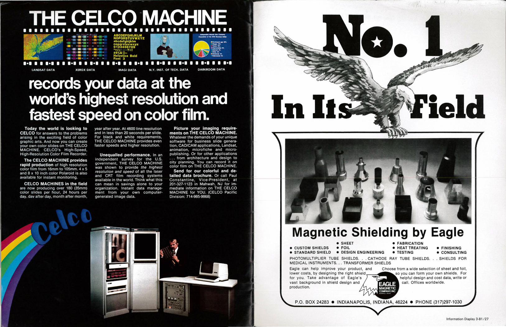
'
In II leld
Magnetic Shielding by Eagle • SHEET • FABRICATION
e CUSTOM SHIELDS • FOIL e HEAT TREATING e FINISHING • STANDARD SHIELD • DESIGN ENGINEERING e TESTING • CONSULTING
PHOTOMULTIPLIER TUBE SHIELDS ... CATHODE RAY TUBE SHIELDS. . SHIELDS FOR MEDICAL INSTRUMENTS ... TRANSFORMER SHIELDS
Eagle can help improve your product, and Choose from a wide selection of sheet and foil, lower costs, by designing the right shield ~~1~~• so you can form your own shields. For for you. Take advantage of Eagle's helpful design and cost data, write or vast background in shie ld design and call. Offices worldwide. production.
P.O. BOX 24283 e INDIANAPOLIS, INDIANA, 46224 e PHONE (317)297-1030
Information Display 3-8 1/ 27