chapter 8 memory management strategies
DESCRIPTION
Bilkent University Department of Computer Engineering CS342 Operating Systems. Chapter 8 Memory Management Strategies. Dr. İ brahim K ö rpeo ğ lu http://www.cs.bilkent.edu.tr/~korpe. Last Update: April 20, 2011. Objectives - PowerPoint PPT PresentationTRANSCRIPT

1
Chapter 8 Memory Management
Strategies Dr. İbrahim Körpeoğlu
http://www.cs.bilkent.edu.tr/~korpe
Bilkent University Department of Computer Engineering
CS342 Operating Systems
Last Update: April 20, 2011

2
Objectives and Outline
Objectives• To provide a detailed description of
various ways of organizing memory hardware
• To discuss various memory-management techniques, including paging and segmentation
• To provide a detailed description of the Intel Pentium, which supports both pure segmentation and segmentation with paging
Outline• Background• Swapping • Contiguous Memory Allocation• Paging• Structure of the Page Table• Segmentation• Example: The Intel Pentium

3
Background
• Program must be brought (from disk) into memory and placed within a process for it to be run
• Main memory and registers are only storage CPU can access directly
• Register access in one CPU clock (or less)
• Main memory can take many cycles
• Cache sits between main memory and CPU registers
• Protection of memory required to ensure correct operation

4
Background
Main Memory
Disk
CPU
Registers
cache
program image in memory
Operating System
Process
instructions
data

5
Program addresses and memory
• When code is generated (or assembly program is written) we use memory addresses for variables, functions and branching/jumping.
• Those addresses can be physical or logical memory addresses.
• In very early systems they are just physical memory addresses. – A program has to be loaded to that
address to run. – No relocation
func
func
func
variable
variable
variable
main
program

6
Program addresses and memory
Jump 8
…
Mov
Add
0
4
8
12
Program
0
4
8
12
16
20
24
28
32
36
40
44
RAMphysical addresses of RAM
Jump 8
…
Mov
Add
Assume they are physical addresses

7
Program addresses and memory
Jump 8
…
Mov
Add
0
4
8
12
Program 1
Jump 12
…
Sub
Cmp
0
4
8
12
Program 2
0
4
8
12
16
20
24
28
32
36
40
44
RAMphysical addresses of RAM
Jump 8
…
Mov
Add
Jump 12
…
Sub
Cmp
Pro
gram
1P
rogr
am 2

8
Logical address space concept
• We need logical address space concept, that is different that the physical RAM (main memory) addresses.
• A program uses logical addresses.
• Set of logical addresses used by the program is its logical address space– Logical address space can
be, for example, [0, max_address]
• Logical address space has to be mapped somewhere in physical memory
RAM
0
phy_max
Program
0
logic_max Program
logicaladdressspace
base
limit

9
Base and Limit Registers
A pair of base and limit registers define the address space of a process
A process should be accessing and using that range.
Protection provided in this way.
Each physical address should be in range [base, base+limit]

10
Binding of Instructions and Data to Memory
• Address binding of instructions and data to (physical) memory addresses can happen at three different stages
– Compile time: If memory location known a priori, absolute code can be generated; must recompile code if starting location changes
– Load time: Must generate relocatable code if memory location is not known at compile time
– Execution time: Binding delayed until run time if the process can be moved during its execution from one memory segment to another. Need hardware support for address maps (e.g., base and limit registers)
RAM
Program
instructions
data
a program
?

11
Multistep Processing of a User Program
Addresses may be represented in different ways during these steps

12
Logical vs. Physical Address Space
• The concept of a logical address space that is bound to a separate physical address space is central to proper memory management
– Logical address – generated by the CPU; also referred to as virtual address
– Physical address – address seen by the memory unit
• Logical and physical addresses are the same in compile-time and load-time address-binding schemes; logical (virtual) and physical addresses differ in execution-time address-binding scheme

13
Logical and physical addresses
CPU Main Memory (RAM)
phys
ical
add
ress
es
int xint y;cmp ..mov r1, M[28]mov r2, M[24]add r1, r2, r3jmp 16mov ..
2824201612080400
60565248444036322824201612080400
int xint y;cmp ..mov r1, M[28]mov r2, M[24]add r1, r2, r3jmp 16mov ..
a relocatable program
logi
cal a
ddre
sses
24 32base limit
mov r1, M[28]
PC
IRM[28+base]
M[28+24]M[52]
14
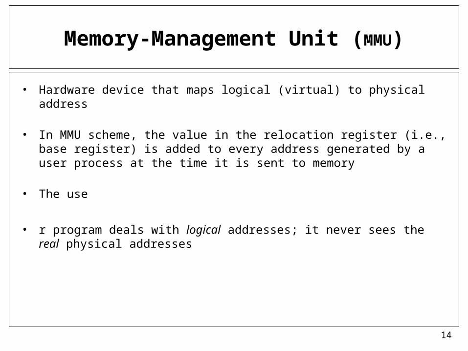
Memory-Management Unit (MMU)
• Hardware device that maps logical (virtual) to physical address
• In MMU scheme, the value in the relocation register (i.e., base register) is added to every address generated by a user process at the time it is sent to memory
• The use
• r program deals with logical addresses; it never sees the real physical addresses

15
Dynamic relocation using a relocation register

16
Dynamic Loading
• Routine is not loaded until it is called
• Better memory-space utilization; unused routine is never loaded
• Useful when large amounts of code are needed to handle infrequently occurring cases
• No special support from the operating system is required implemented through program design

17
Dynamic Linking
• Linking postponed until execution time
• Small piece of code, stub, used to locate the appropriate memory-resident library routine
• Stub replaces itself with the address of the routine, and executes the routine
• Operating system needed to check if routine is in processes’ memory address
• Dynamic linking is particularly useful for libraries
– Standard C library is shared library that is dynamically linked, not statically linked.
– You can link statically if you want.
• System also known as shared libraries

18
Swapping
• A process can be swapped temporarily out of memory to a backing store, and then brought back into memory for continued execution
• Backing store – fast disk large enough to accommodate copies of all memory images for all users; must provide direct access to these memory images
• Roll out, roll in – swapping variant used for priority-based scheduling algorithms; lower-priority process is swapped out so higher-priority process can be loaded and executed
• Major part of swap time is transfer time; total transfer time is directly proportional to the amount of memory swapped
• Modified versions of swapping are found on many systems (i.e., UNIX, Linux, and Windows)
• System maintains a ready queue of ready-to-run processes which have memory images on disk

19
Schematic View of Swapping

20
Contiguous Allocation
• Main memory is partitioned usually into two partitions:
– Resident operating system, usually held in low memory with interrupt vector
– User processes then held in high memory
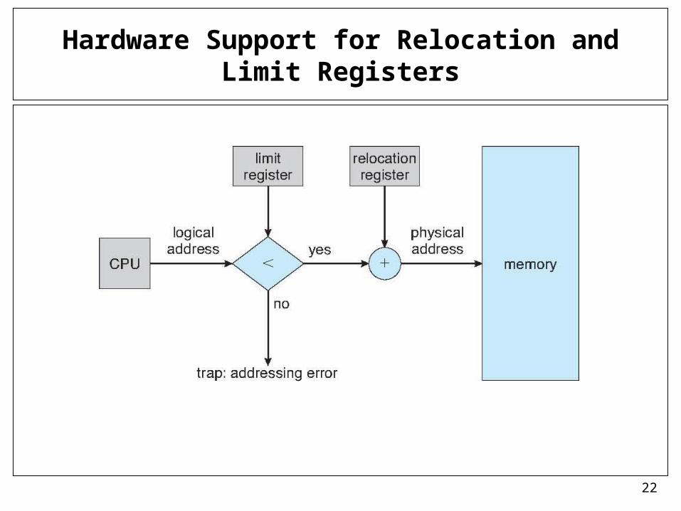
• Relocation registers used to protect user processes from each other, and from changing operating-system code and data
– Base register contains value of smallest physical address
– Limit register contains range of logical addresses – each logical address must be less than the limit register
– MMU maps logical addresses dynamically

21
Basic Memory Allocation Strategies
• In this chapter, we will cover 3 basic main memory allocation strategies to processes
– 1) Contiguous allocation
– 2) Paging
– 3) Segmentation
22
Hardware Support for Relocation and Limit Registers
23
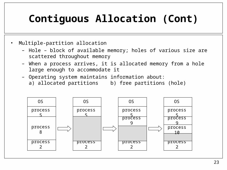
Contiguous Allocation (Cont)
• Multiple-partition allocation– Hole – block of available memory; holes of various size are scattered throughout
memory– When a process arrives, it is allocated memory from a hole large enough to
accommodate it– Operating system maintains information about:
a) allocated partitions b) free partitions (hole)
OS
process 5
process 8
process 2
OS
process 5
process 2
OS
process 5
process 2
OS
process 5
process 9
process 2
process 9
process 10

24
Dynamic Storage-Allocation Problem
• First-fit: Allocate the first hole that is big enough• Best-fit: Allocate the smallest hole that is big enough; must search
entire list, unless ordered by size – Produces the smallest leftover hole
• Worst-fit: Allocate the largest hole; must also search entire list – Produces the largest leftover hole
How to satisfy a request of size n from a list of free holes
First-fit and best-fit better than worst-fit in terms of speed and storage utilization

25
Fragmentation
• External Fragmentation – total memory space exists to satisfy a request, but it is not contiguous
• Internal Fragmentation – allocated memory may be slightly larger than requested memory; this size difference is memory internal to a partition (allocation), but not being used
• Reduce external fragmentation by compaction
– Shuffle memory contents to place all free memory together in one large block
– Compaction is possible only if relocation is dynamic, and is done at execution time
– I/O problem
• Latch job in memory while it is involved in I/O
• Do I/O only into OS buffers

26
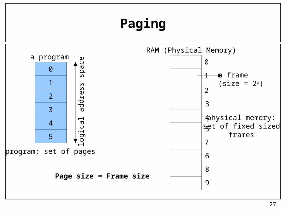
Paging
• Physical address space of a process can be noncontiguous; process is allocated physical memory whenever the latter is available
– Physical address space will also be noncontiguous.
• Divide physical memory into fixed-sized blocks called frames (size is power of 2, between 512 bytes and 8,192 bytes)
• Divide logical memory into blocks of same size called pages
• Keep track of all free frames
• To run a program of size n pages, need to find n free frames and load program
• Set up a page table to translate logical to physical addresses
• Internal fragmentation
27
Paging
RAM (Physical Memory)
a frame(size = 2x)
physical memory:set of fixed sized
frames
0
1
2
3
4
5
a program
logi
cal a
ddre
ss s
pace
0
1
2
3
4
5
7
6
8
9Page size = Frame size
program: set of pages

28
Paging
0
1
2
3
4
5
7
6
8
9
RAM
0
1
2
3
4
5
a program
load
0
1
2
3
5
0 mapped_to 11 mapped_to 42 mapped_to 23 mapped_to 74 mapped_to 95 mapped_to 6 4
page table

29
Example

30
Address Translation Scheme
– Assume Logical Addresses are m bits. Then logical address space is 2m bytes.
– Assume page size is 2n bytes.
• Logical Address generated by CPU is divided into:
– Page number (p) – used as an index into a page table which contains base address of each page in physical memory
– Page offset (d) – combined with base address to define the physical memory address that is sent to the memory unit
page number page offset
p d
(m – n) bits n bits
m bits

31
Simple example
Assume m is 3 and n is 2
000001010011100101110111
Logical addresses
000001010011100101110111
page0
page1

32
Paging Hardware: address translation

33
Paging Example
32 b
yte
mem
ory
page size = 4 bytes= 22
4 bit logical address
page number
offset(dispacement)
insidepage
LA = 5PA = ?
LA = 11PA = ?
LA = 13PA = ?
5 is 0101
11 is 1011
13 is 1101
PA = 11001
PA = 00111
PA = 01001

34
Address translation example 1
0010000000000100
16 bit logical address
page size = 4096 bytes(offset is 12 bits)p# offset
000 0000000000
000
111 1000101000
010
000 0000011100
011
000 1110001010
111
1514131211109876543210
110000000000100
f# offset
mapping
page table
15 bit physical address
valid/invalid bit
frame number

35
EFGH
EFGH
ABCD
ABCD
Address translation example 2
000001010011100101110111
Logical Memory
m=3; 23 = 8 logical addressesn=2; page size = 22 = 4
page 0
page 1
0000000100100011010001010110011110001001101010111100110111101111
frame 00
frame 01
frame 10
frame 11
Physical Memory
1 bit for page#
2 bits for offset
2 bits for frame#
page table
0
11110
each entry is used to map4 addresses (page size addresses)

36
Free Frames
Before allocation After allocation
OS keeps infoabout the framesin its frame table

37
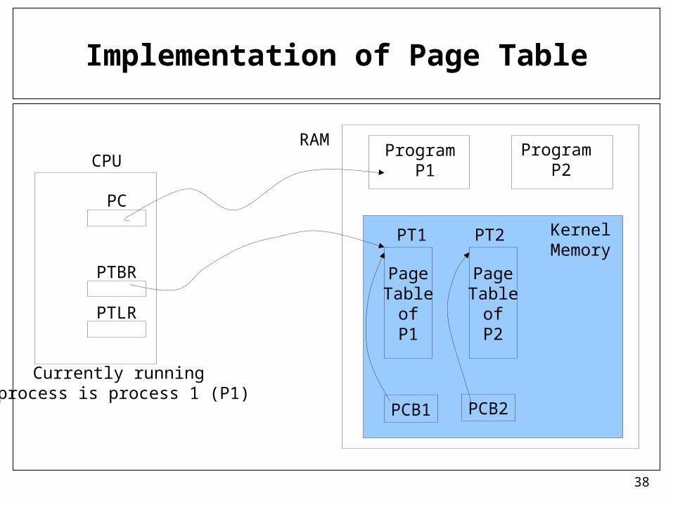
Implementation of Page Table
• Page table is kept in main memory
• Page-table base register (PTBR) points to the page table
• Page-table length register (PTLR) indicates size of the page table
• In this scheme every data/instruction access requires two memory accesses. One for the page table and one for the data/instruction.
• The two memory access problem can be solved by the use of a special fast-lookup hardware cache called associative memory or translation look-aside buffers (TLBs)
• Some TLBs store address-space identifiers (ASIDs) in each TLB entry – uniquely identifies each process to provide address-space protection for that process
38
Implementation of Page Table
PageTable
ofP1
PageTable
ofP2
PT1 PT2
PCB1 PCB2
KernelMemory
RAMCPU
PTBR
PTLR
PC
Program P1
Program P2
Currently running process is process 1 (P1)

39
TLB Associative Memory
• Associative memory – parallel search
Address translation (p, d)
– If p is in TLB, get frame # out
– Otherwise get frame # from page table in memory
Page # Frame #

40
Paging Hardware With TLB

41
Effective Memory Access Time
• TLB (associative registers) Lookup = time unit
• Assume memory cycle time is 1 microsecond
• Hit ratio – percentage of times that a page number is found in the TLB; ratio related to the TLB size
• Hit ratio =
• Effective Access Time (EAT)
EAT = (1 + ) + (2 + )(1 – )
= 2 + –

42
Memory Protection
• Memory protection implemented by associating a protection bit with each page
– Read only page
– Executable page
– Read-write page
• Valid-invalid bit attached to each entry in the page table:
– “valid” indicates that the page is in the process’ logical address space, and is thus a legal page
– “invalid” indicates that the page is not in the process’ logical address space

43
Valid (v) or Invalid (i) Bit In A Page Table

44
Page Table Entry Structure
• A typical size of a page table entry can be 32 bits. Depends on the architecture
• Typically we have the following fields in a page table entry.
Page Frame NumberReserved
Caching Disabled
bit
Referenced bit
Modified(Dirty)
bit
Protection bits (read, read-write, execute)
Valid/Invalid(Present/Absent)
bit

45
Shared Pages
• Shared code
– One copy of read-only (reentrant) code shared among processes (i.e., text editors, compilers, window systems).
– Shared code must appear in same location in the logical address space of all processes
• Private code and data
– Each process keeps a separate copy of the code and data
– The pages for the private code and data can appear anywhere in the logical address space

46
Shared Pages Example
47
Structure of the Page Table
• Hierarchical Paging
• Hashed Page Tables
• Inverted Page Tables

48
Hierarchical Page Tables
• Break up the logical address space into multiple page tables
• A simple technique is a two-level page table
PT
Log MemLog MemPT
00
01
10
11
00011011

49
Two-Level Paging Scheme

50
Two-Level Paging Scheme
0000000100100011010001010110011110001001101010111100110111101111
single level Page table
00011011
00011011
00011011
00011011
00011011
two-level page table
offsetlogical address
offsetlogical address

51
Two-Level Paging Example
• A logical address (on 32-bit machine with 1K page size) is divided into:– a page number consisting of 22 bits– a page offset consisting of 10 bits
• Since the page table is paged, the page number is further divided into:– a 12-bit page number – a 10-bit page offset
• Thus, a logical address is as follows:
where pi is an index into the outer page table, and p2 is the index into the inner page table
page number page offset
p1 p2 d
12 10 10

52
Address-Translation Scheme

53
Example: two level page table need
logical address length = 32 bitspagesize = 4096 byteslogical address division: 10, 10, 12
used
used
unused
12 MB
8 MB
232 bytes = 4 GBWhat is total size of two
level page table if entry size
is 4 bytes?logical address space size
(only partially used)

54
Example: two level page table need
10 10 12
210
entries
210
entries
210
entriesTop level page table
a second level pagetable
……
Each entry of a secondlevel page table translates
a page# to a frame#;i.e. each entry maps a page
which is 4096 bytes
There are 1024 entries In a second level page table
Hence, a second levelpage table can map210 * 212 = 222 = 4 MB
of logical address space

55
Example: two level page table need
12 MB
8 MB
232 bytes = 4 GB
12 MB / 4 MB = 3 second level page tables required to map 12 MB
of logical memory
8 MB / 4 MB = 2 second level page tables required to map8 MB of logical memory
Total = 3 + 2 = 5 second levelpage tables required

56
Example: two level page table need
12 MB
8 MB
232 bytes = 4 GB
….unused
210
entries
210
entries
210
entries
210
entries
210
entries
2nd level page tables
top level page table
210 entries
1K * 4Bytes +5 * 1K * 4Bytes
= 24 KBspace needed
to holdthe page
tables of theprocess

57
Three-level Paging Scheme
64 bit addresses

58
Hashed Page Tables
• Common in address spaces > 32 bits
• Page table is a hash table
• A virtual page number is hashed into a page table entry
• A page table entry contains a chain of elements hashing to the same location
– each element = <a virtual page number, frame number>
• Virtual page numbers are compared in this chain searching for a match
– If a match is found, the corresponding physical frame is extracted

59
Hashed Page Table
virtual page number
frame number

60
Inverted Page Table
• One entry for each real page frame of physical memory
• Entry consists of the page number of the virtual page stored in that real memory location (frame), with information about the process that owns that page
– Entry content: <pid, virtual page number>
• Decreases memory needed to store each page table, but increases time needed to search the table when a page reference occurs

61
Inverted Page Table Architecture
62
Segmentation
• Memory-management scheme that supports user view of memory
• A program is a collection of segments– A segment is a logical unit such as:
main programprocedure functionmethodobjectlocal variables, global variablescommon blockstacksymbol tablearrays
63
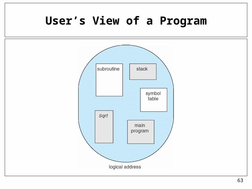
User’s View of a Program

64
Logical View of Segmentation
1
3
2
4
1
4
2
3
user space physical memory space
segment

65
Segmentation Architecture
• Logical address consists of a two tuple:
<segment-number, offset>
• Segment table – maps two-dimensional logical addresses; each table entry has:
– base – contains the starting physical address where the segments reside in memory
– limit – specifies the length of the segment
• Segment-table base register (STBR) points to the segment table’s location in memory
• Segment-table length register (STLR) indicates number of segments used by a program;
segment number s is legal if s < STLR
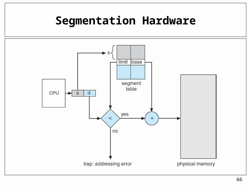
66
Segmentation Hardware

67
Segmentation Architecture (Cont.)
• Protection– With each entry in segment table associate:
• validation bit = 0 illegal segment• read/write/execute privileges
• Protection bits associated with segments; code sharing occurs at segment level– Code segment: READONLY; sharable; …– Data segment: RED-WRITE; not-sharable
• Since segments vary in length, memory allocation is a dynamic storage-allocation problem

68
Example of Segmentation
69
Example: The Intel Pentium
• Supports both segmentation and segmentation with paging
• CPU generates logical address (<segment#, offset> pairs)
– Given to segmentation unit
• Which produces linear addresses
– Linear address given to paging unit
• Which generates physical address in main memory
• Paging unit forms equivalent of MMU
70
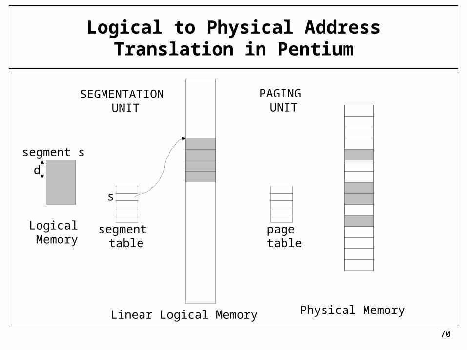
Logical to Physical Address Translation in Pentium
Linear Logical Memory
segment s
s
d
Logical Memory
Physical Memory
segment table
page table
SEGMENTATION UNIT
PAGING UNIT

71
Logical to Physical Address Translation in Pentium

72
Intel Pentium Segmentation
base address limit
base
base+offset

73
Pentium Paging Architecture
• Pentium architecture allows a page size of either 4 KB or 4 MB.
• For 4 KB pages, two-level paging scheme is used in a 32 bit machine– Address division: <10, 10, 12> bits
• For 4 MB pages, we can skip the inner page tables (secondary page table). A top level page table entry will point directly to a 4 MB page.

74
Pentium Paging Architecture
75
Linux on Pentium: Segmentation
• Linux is designed to run on a lot of hardware platforms: Pentium, Arm, Motorola, Sparc, MIPS, …
• Therefore it does not rely on segmentation and makes minimal use of segmentation in Pentium.

76
Linux on Pentium: Paging
• Linux can run both on 32 bit and 64 bit machines. – Therefore having just two level paging is not enough. – Linux adapted a three level paging that can be used both in 32bit and 64bit
machines.
• A linear address in Linux is broken into 4 parts: – P1: global directory– P2: middle directory– P3: page table– P4: offset
• Number of bits in each part depends on the architecture

77
Linear Address in Linux
• In a 64 bit machine (very large address space), we use all 4 parts
• In a 32 bit Intel machine, that uses two-level paging, we ignore the middle directory (its size is 0), and use 3 parts.
Broken into four parts:

78
Three-level Paging in Linux

79
Linux Paging: some kernel structures
struct mm_struct {
…pgd_t *pgd;….
}
struct task_struct {
……struct mm_struct *mm;
}
the PCB objectof a process X
top level page table
of process X(calledpage global
directory)
mm objectof process X
(keeps memory management
related information)

80
References
• The slides here are adapted/modified from the textbook and its slides: Operating System Concepts, Silberschatz et al., 7th & 8th editions, Wiley.
• Operating System Concepts, 7th and 8th editions, Silberschatz et al. Wiley.
• Modern Operating Systems, Andrew S. Tanenbaum, 3rd edition, 2009.