chapter 5 natural gas development activities & …... chapter 5 natural gas development...
TRANSCRIPT

www.dec.ny.gov
Chapter 5 Natural Gas Development Activities & High-Volume
Hydraulic Fracturing Final
Supplemental Generic Environmental Impact Statement

This page intentionally left blank.

Final SGEIS 2015, Page 5-i
Chapter 5 - Natural Gas Development Activities & High-Volume Hydraulic Fracturing
CHAPTER 5 NATURAL GAS DEVELOPMENT ACTIVITIES & HIGH-VOLUME HYDRAULIC FRACTURING .................. 5-1
5.1 LAND DISTURBANCE ..................................................................................................................................... 5-2 5.1.1 Access Roads .............................................................................................................................................. 5-2 5.1.2 Well Pads ................................................................................................................................................... 5-6 5.1.3 Utility Corridors ....................................................................................................................................... 5-10 5.1.4 Well Pad Density ...................................................................................................................................... 5-11
5.1.4.1 Historic Well Density ..................................................................................................................... 5-11 5.1.4.2 Anticipated Well Pad Density ....................................................................................................... 5-12
5.2 HORIZONTAL DRILLING ................................................................................................................................ 5-19 5.2.1 Drilling Rigs .............................................................................................................................................. 5-21 5.2.2 Multi-Well Pad Development .................................................................................................................. 5-23 5.2.3 Drilling Mud ............................................................................................................................................. 5-27 5.2.4 Cuttings .................................................................................................................................................... 5-28
5.2.4.1 Cuttings Volume............................................................................................................................ 5-29 5.2.4.2 NORM in Marcellus Cuttings ......................................................................................................... 5-29
5.2.5 Management of Drilling Fluids and Cuttings ........................................................................................... 5-32 5.2.5.1 Reserve Pits on Multi-Well Pads ................................................................................................... 5-32 5.2.5.2 Closed-Loop Tank Systems ............................................................................................................ 5-32
5.3 HYDRAULIC FRACTURING .............................................................................................................................. 5-34
5.4 FRACTURING FLUID ..................................................................................................................................... 5-35 5.4.1 Properties of Fracturing Fluids ................................................................................................................ 5-44 5.4.2 Classes of Additives ................................................................................................................................. 5-44 5.4.3 Composition of Fracturing Fluids ............................................................................................................. 5-46
5.4.3.1 Chemical Categories and Health Information ............................................................................... 5-58
5.5 TRANSPORT OF HYDRAULIC FRACTURING ADDITIVES ........................................................................................... 5-72
5.6 ON-SITE STORAGE AND HANDLING OF HYDRAULIC FRACTURING ADDITIVES .............................................................. 5-73 5.6.1 Summary of Additive Container Types .................................................................................................... 5-74
5.7 SOURCE WATER FOR HIGH-VOLUME HYDRAULIC FRACTURING .............................................................................. 5-76 5.7.1 Delivery of Source Water to the Well Pad ............................................................................................... 5-77 5.7.2 Use of Centralized Impoundments for Fresh Water Storage .................................................................. 5-78
5.8 HYDRAULIC FRACTURING DESIGN ................................................................................................................... 5-81 5.8.1 Fracture Development ............................................................................................................................. 5-82 5.8.2 Methods for Limiting Fracture Growth.................................................................................................... 5-83 5.8.3 Hydraulic Fracturing Design – Summary .................................................................................................. 5-84
5.9 HYDRAULIC FRACTURING PROCEDURE ............................................................................................................. 5-85
5.10 RE-FRACTURING ......................................................................................................................................... 5-89
5.11 FLUID RETURN ........................................................................................................................................... 5-92 5.11.1 Flowback Water Recovery ....................................................................................................................... 5-93 5.11.2 Flowback Water Handling at the Wellsite ............................................................................................... 5-93 5.11.3 Flowback Water Characteristics .............................................................................................................. 5-93
5.11.3.1 Temporal Trends in Flowback Water Composition ..................................................................... 5-111 5.11.3.2 NORM in Flowback Water .......................................................................................................... 5-112

Final SGEIS 2015, Page 5-ii
5.12 FLOWBACK WATER TREATMENT, RECYCLING AND REUSE.................................................................................... 5-112 5.12.1 Physical and Chemical Separation ......................................................................................................... 5-114 5.12.2 Dilution .................................................................................................................................................. 5-116
5.12.2.1 Reuse .......................................................................................................................................... 5-116 5.12.3 Other On-Site Treatment Technologies ................................................................................................. 5-118
5.12.3.1 Membranes / Reverse Osmosis .................................................................................................. 5-118 5.12.3.2 Thermal Distillation ..................................................................................................................... 5-119 5.12.3.3 Ion Exchange ............................................................................................................................... 5-120 5.12.3.4 Electrodialysis/Electrodialysis Reversal ...................................................................................... 5-120 5.12.3.5 Ozone/Ultrasonic/Ultraviolet ..................................................................................................... 5-121 5.12.3.6 Crystallization/Zero Liquid Discharge ......................................................................................... 5-122
5.12.4 Comparison of Potential On-Site Treatment Technologies ................................................................... 5-122
5.13 WASTE DISPOSAL ..................................................................................................................................... 5-123 5.13.1 Cuttings from Mud Drilling .................................................................................................................... 5-123 5.13.2 Reserve Pit Liner from Mud Drilling....................................................................................................... 5-124 5.13.3 Flowback Water ..................................................................................................................................... 5-124
5.13.3.1 Injection Wells ............................................................................................................................ 5-125 5.13.3.2 Municipal Sewage Treatment Facilities ...................................................................................... 5-126 5.13.3.3 Out-of-State Treatment Plants ................................................................................................... 5-126 5.13.3.4 Road Spreading ........................................................................................................................... 5-127 5.13.3.5 Private In-State Industrial Treatment Plants .............................................................................. 5-127 5.13.3.6 Enhanced Oil Recovery ............................................................................................................... 5-128
5.13.4 Solid Residuals from Flowback Water Treatment ................................................................................. 5-128
5.14 WELL CLEANUP AND TESTING ...................................................................................................................... 5-128
5.15 SUMMARY OF OPERATIONS PRIOR TO PRODUCTION .......................................................................................... 5-129
5.16 NATURAL GAS PRODUCTION ....................................................................................................................... 5-131 5.16.1 Partial Site Reclamation ......................................................................................................................... 5-131 5.16.2 Gas Composition .................................................................................................................................... 5-131
5.16.2.1 Hydrocarbons .............................................................................................................................. 5-131 5.16.2.2 Hydrogen Sulfide......................................................................................................................... 5-132
5.16.3 Production Rate ..................................................................................................................................... 5-132 5.16.4 Well Pad Production Equipment ........................................................................................................... 5-133 5.16.5 Brine Storage ......................................................................................................................................... 5-135 5.16.6 Brine Disposal ........................................................................................................................................ 5-135 5.16.7 NORM in Marcellus Production Brine .................................................................................................... 5-135 5.16.8 Gas Gathering and Compression ........................................................................................................... 5-136
5.17 WELL PLUGGING ...................................................................................................................................... 5-137

Final SGEIS 2015, Page 5-iii
FIGURES Figure 5.1 - Well Pad Schematic .............................................................................................................................. 5-10 Figure 5.2 - Possible well spacing unit configurations and wellbore paths ............................................................. 5-26 Figure 5.3 - Sample Fracturing Fluid Composition (12 Additives), by Weight, from Fayetteville Shale .................. 5-47 Figure 5.4 - Sample Fracturing Fluid Composition (9 Additives), by Weight, from Marcellus Shale (New July
2011) .................................................................................................................................................. 5-48 Figure 5.5 - Sample Fracturing Fluid Composition (6 Additives), by Weight, from Marcellus Shale (New July
2011) .................................................................................................................................................. 5-48 Figure 5.6 - Example Fracturing Fluid Composition Including Recycled Flowback Water (New July 2011) .......... 5-117 Figure 5.7 - One configuration of potential on-site treatment technologies. ....................................................... 5-118 Figure 5.8 – Simplified Illustration of Gas Production Process .............................................................................. 5-134
TABLES Table 5.1 - Ten square mile area (i.e., 6,400 acres), completely drilled with horizontal wells in multi-well
units or vertical wells in single-well units (Updated July 2011) ......................................................... 5-19 Table 5.2 - 2009 Marcellus Radiological Data .......................................................................................................... 5-30 Table 5.3 - Gamma Ray Spectroscopy ..................................................................................................................... 5-31 Table 5.4 - Fracturing Additive Products – Complete Composition Disclosure Made to the Department
(Updated July 2011) ........................................................................................................................... 5-37 Table 5.5 - Fracturing Additive Products – Partial Composition Disclosure to the Department (Updated July
2011) .................................................................................................................................................. 5-42 Table 5.6 - Types and Purposes of Additives Proposed for Use in New York State (Updated July 2011) ................ 5-45 Table 5.7 - Chemical Constituents in Additives (Updated July 2011) ...................................................................... 5-49 Table 5.8 - Categories based on chemical structure of potential fracturing fluid constituents. (Updated July
2011) .................................................................................................................................................. 5-58 Table 5.9 - Parameters present in a limited set of flowback analytical results (Updated July 2011) ...................... 5-95 Table 5.10 - Typical concentrations of flowback constituents based on limited samples from PA and WV,
and regulated in NY (Revised July 2011) ............................................................................................ 5-99 Table 5.11 - Typical concentrations of flowback constituents based on limited samples from PA and WV,
not regulated in NY(Revised July 2011) ............................................................................................ 5-102 Table 5.12 - Conventional Analytes In MSC Study (New July 2011) ...................................................................... 5-103 Table 5.13 - Total and Dissolved Metals Analyzed In MSC Study (New July 2011) ................................................ 5-104 Table 5.14 - Volatile Organic Compounds Analyzed in MSC Study (New July 2011) ............................................. 5-105 Table 5.15 - Semi-Volatile Organics Analyzed in MSC Study (New July 2011) ....................................................... 5-106 Table 5.16 - Organochlorine Pesticides Analyzed in MSC Study (New July 2011) ................................................. 5-107 Table 5.17 - PCBs Analyzed in MSC Study (New July 2011) ................................................................................... 5-107 Table 5.18 - Organophosphorus Pesticides Analyzed in MSC Study (New July 2011) ........................................... 5-107 Table 5.19 - Alcohols Analyzed in MSC Study (New July 2011) ............................................................................. 5-107 Table 5.20 - Glycols Analyzed in MSC Study (New July 2011)................................................................................ 5-107 Table 5.21 - Acids Analyzed in MSC Study (New July 2011) .................................................................................. 5-107 Table 5.22 - Parameter Classes Analyzed for in the MSC Study (New July 2011) .................................................. 5-108 Table 5.23 - Parameter Classes Detected in Flowback Analyticals in MSC Study (New July 2011) ....................... 5-109 Table 5.24 - Concentrations of NORM constituents based on limited samples from PA and WV (Revised
July 2011) ......................................................................................................................................... 5-112 Table 5.25 - Maximum allowable water quality requirements for fracturing fluids, based on input from one
expert panel on Barnett Shale (Revised July 2011) .......................................................................... 5-113 Table 5.26 - Treatment capabilities of EDR and RO Systems ................................................................................. 5-121 Table 5.27 - Summary of Characteristics of On-Site Flowback Water Treatment Technologies (Updated July
2011) ................................................................................................................................................ 5-123 Table 5.28 - Out-of-state treatment plants proposed for disposition of NY flowback water ................................ 5-127 Table 5.29 - Primary Pre-Production Well Pad Operations (Revised July 2011) .................................................... 5-129 Table 5.30 - Marcellus Gas Composition from Bradford County, PA ..................................................................... 5-131

Final SGEIS 2015, Page 5-iv
PHOTOS Photo 5.1 - Access Road and Erosion/Sedimentation Controls, Salo 1, Barton, Tioga County NY ............................ 5-4 Photo 5.2 - Access Road, Nornew Smyrna Hillbillies 2H, Smyrna, Madison County NY ............................................ 5-4 Photo 5.3 - In-Service Access Road to Horizontal Marcellus well in Bradford County PA ......................................... 5-5 Photo 5.4 - Access Road and Sedimentation Controls, Moss 1, Corning, Steuben County NY .................................. 5-5 Photo 5.5 - Chesapeake Energy Marcellus Well Drilling, Bradford County, PA ......................................................... 5-8 Photo 5.6 - Hydraulic fracturing operation, Horizontal Marcellus Well, Upshur County, WV .................................. 5-8 Photo 5.7 - Hydraulic Fracturing Operation, Horizontal Marcellus Well, Bradford County, PA ................................ 5-9 Photo 5.8 - Locations of Over 44,000 Natural Gas Wells Targeting the Medina Formation, Chautauqua
County NY ........................................................................................................................................... 5-13 Photo 5.9 - Locations of 48 Natural Gas Wells Targeting the Medina Formation, Chautauqua County NY ............ 5-14 Photo 5.10 - Locations of 28 Wells in the Town of Poland, Chautauqua County NY ............................................... 5-15 Photo 5.11 - Locations of 77 Wells in the Town of Sheridan, Chautauqua County NY............................................ 5-16 Photo 5.12 - Double Drilling Rig, Union Drilling Rig 54, Olsen 1B, Town of Fenton, Broome County NY ................ 5-24 Photo 5.13 - Double Drilling Rig, Union Drilling Rig 48, Salo 1, Town of Barton, Tioga County NY ......................... 5-24 Photo 5.14 - Triple Drilling Rig, Precision Drilling Rig 26, Ruger 1, Horseheads, Chemung County NY ................... 5-25 Photo 5.15 - Top Drive Single Drilling Rig, Barber and DeLine Rig, Sheckells 1, Town of Cherry Valley,
Otsego County NY .............................................................................................................................. 5-25 Photo 5.16 - Drilling rig mud system (blue tanks) ................................................................................................... 5-28 Photo 5.17 - Sand used as proppant in hydraulic fracturing operation in Bradford County, PA ............................. 5-47 Photo 5.18 - Transport trucks with totes ................................................................................................................. 5-75 Photo 5.19 - Fortuna SRBC-Approved Chemung River Water Withdrawal Facility, Towanda PA ........................... 5-79 Photo 5.20 - Fresh Water Supply Pond .................................................................................................................... 5-79 Photo 5.21 - Water Pipeline from Fortuna Centralized Freshwater Impoundments, Troy PA ................................ 5-79 Photo 5.22 - Construction of Freshwater Impoundment, Upshur County WV........................................................ 5-80 Photo 5.23 - Personnel monitoring a hydraulic fracturing procedure. Source: Fortuna Energy. ............................ 5-84 Photo 5.24 - Three Fortuna Energy wells being prepared for hydraulic fracturing, with 10,000 psi well head
and goat head attached to lines. Troy PA. Source: New York State Department of Environmental Conservation 2009 ..................................................................................................... 5-86
Photo 5.25 - Hydraulic Fracturing Operation Equipment at a Fortuna Energy Multi-Well Site, Troy PA ................ 5-90 Photo 5.26 - Fortuna Energy Multi-Well Site in Troy PA After Removal of Most Hydraulic Fracturing
Equipment .......................................................................................................................................... 5-91 Photo 5.27 - Wellhead and Fracturing Equipment .................................................................................................. 5-91 Photo 5.28 - Pipeline Compressor in New York. Source: Fortuna Energy ............................................................. 5-137

Final SGEIS 2015, Page 5-1
Chapter 5 NATURAL GAS DEVELOPMENT ACTIVITIES & HIGH-VOLUME
HYDRAULIC FRACTURING
As noted in the 1992 GEIS, New York has a long history of natural gas production. The first gas
well was drilled in 1821 in Fredonia, and the 40 Bcf of gas produced in 1938 remained the
production peak until 2004 when 46.90 Bcf were produced. Annual production exceeded 50 Bcf
from 2005 through 2008, dropping to 44.86 Bcf in 2009 and 35.67 Bcf in 2010. Chapters 9 and
10 of the 1992 GEIS comprehensively discuss well drilling, completion and production
operations, including potential environmental impacts and mitigation measures. The history of
hydrocarbon development in New York through 1988 is also covered in the 1992 GEIS.
New York counties with actively producing gas wells reported in 2010 were: Allegany,
Cattaraugus, Cayuga, Chautauqua, Chemung, Chenango, Erie, Genesee, Livingston, Madison,
Niagara, Ontario, Oswego, Schuyler, Seneca, Steuben, Tioga, Wayne, Wyoming and Yates.
Hydraulic fracturing is a well stimulation technique which consists of pumping a fluid and a
proppant such as sand down the wellbore under high pressure to create fractures in the
hydrocarbon-bearing rock. No blast or explosion is created by the hydraulic fracturing process.
The proppant holds the fractures open, allowing hydrocarbons to flow into the wellbore after
injected fluids are recovered. Hydraulic fracturing technology was first developed in the late 1940s
and, accordingly, it was addressed in the 1992 GEIS. It is estimated that as many as 90% of wells
drilled in New York are hydraulically fractured. ICF International provides the following
history:121
Hydraulic Fracturing Technological Milestones 122 Early 1900s Natural gas extracted from shale wells. Vertical wells fractured with foam. 1983 First gas well drilled in Barnett Shale in Texas 1980-1990s Cross-linked gel fracturing fluids developed and used in vertical wells 1991 First horizontal well drilled in Barnett Shale 1991 Orientation of induced fractures identified 1996 Slickwater fracturing fluids introduced 1996 Microseismic post-fracturing mapping developed 1998 Slickwater refracturing of originally gel-fractured wells 2002 Multi-stage slickwater fracturing of horizontal wells 2003 First hydraulic fracturing of Marcellus Shale123 2005 Increased emphasis on improving the recovery factor 2007 Use of multi-well pads and cluster drilling
121 ICF Task 1, 2009, p. 3. 122 Matthews, 2008, as cited by ICF Task 1, 2009, p. 3. 123 Harper, 2008, as cited by ICF Task 1, 2009, p. 3.

Final SGEIS 2015, Page 5-2
5.1 Land Disturbance
Land disturbance directly associated with high-volume hydraulic fracturing will consist primarily
of constructed gravel access roads, well pads and utility corridors. According to the most recent
industry estimates, the average total disturbance associated with a multi-well pad, including
incremental portions of access roads and utility corridors, during the drilling and fracturing stage
is estimated at 7.4 acres and the average total disturbance associated with a well pad for a single
vertical well during the drilling and fracturing stage is estimated at 4.8 acres. As a result of
required partial reclamation, this would generally be reduced to averages of about 5.5 acres and
4.5 acres, respectively, during the production phase. These estimates include access roads to the
well pads and incremental portions of utility corridors including gathering lines and compressor
facilities, and the access roads associated with compressor facilities. These associated roads and
facilities are projected to account for, on average, about 3.95 acres of the land area associated
with each pad for the life of the wells. During the long-term production phase, a multi-well pad
itself would occupy about 1.5 acres, while a well pad for a single vertical well would occupy
about 0.5 acre.124,125
5.1.1 Access Roads
The first step in developing a natural gas well site is to construct the access road and well pad.
For environmental review and permitting purposes, the acreage and disturbance associated with
the access road is considered part of the project as described by Topical Response #4 in the 1992
GEIS. However, instead of one well per access road as was typically the case when the GEIS
was prepared, most shale gas development will consist of several wells on a multi-well pad
serviced by a single access road. Therefore, in areas developed by horizontal drilling using
multi-well pads, fewer access roads as a function of the number of wells will be needed.
Industry estimates that 90% of the wells used to develop the Marcellus Shale will be horizontal
wells located on multi-well pads.126
Access road construction involves clearing the route and preparing the surface for movement of
heavy equipment, or reconstruction or improvement of existing roads if present on the property 124 ALL Consulting, 2010, pp. 14 – 15. 125 Cornue, 2011. 126 ALL Consulting, 2010, pp. 7 – 15.

Final SGEIS 2015, Page 5-3
being developed. Ground surface preparation for new roads typically involves staking, grading,
stripping and stockpiling of topsoil reserves, then placing a layer of crushed stone, gravel, or
cobbles over geotextile fabric. Sedimentation and erosion control features are also constructed
as needed along the access roads and culverts may be placed across ditches at the entrance from
the main highway or in low spots along the road.
The size of the access road is dictated by the size of equipment to be transported to the well site,
distance of the well pad from an existing road and the route dictated by property access rights
and environmental concerns. The route selected may not be the shortest distance to the nearest
main road. Routes for access roads may be selected to make use of existing roads on a property
and to avoid disturbing environmentally sensitive areas such as protected streams, wetlands, or
steep slopes. Property access rights and agreements and traffic restrictions on local roads may
also limit the location of access routes.
Access road widths would generally range from 20 to 40 feet during the drilling and fracturing
phase and from 10 to 20 feet during the production phase. During the construction and drilling
phase, additional access road width is necessary to accommodate stockpiled topsoil and
excavated material along the roadway and to construct sedimentation and erosion control
features such as berms, ditches, sediment traps or sumps, or silt fencing along the length of the
access road.
Each 150 feet of a 30-foot wide access road adds about one-tenth of an acre to the total surface
acreage disturbance attributed to the well site. Industry estimates an average access road size of
0.27 acre,127 which would imply an average length of about 400 feet for a 30-foot wide road.
Permit applications for horizontal Marcellus wells received by the Department prior to
publication of the 2009 draft SGEIS indicated road lengths ranging from 130 feet to
approximately 3,000 feet.
Photo 5.1, Photo 5.2, Photo 5.3, and Photo 5.4 depict typical wellsite access roads.
127 Cornue, 2011.

Photo 5.1 Access road and erosion/sedimentation controls, Salo 1, Barton, Tioga County NY. Photo taken during drilling phase. This access road is approximately 1,400 feet long. Road width averages 22 feet wide, 28 feet wide at creek crossing (foreground). Width including drainage ditches is approximately 27 feet. Source: NYS DEC 2007.
Photo 5.2 Nornew, Smyrna Hillbillies #2H, access road, Smyrna, Madison County NY. Photo taken during drilling phase of improved existing private dirt road (approximately 0.8 miles long). Not visible in photo is an additional 0.6 mile of new access road construction. Operator added ditches, drainage, gravel & silt fence to ex-isting dirt road. The traveled part of the road surface in the picture is 12.5' wide; width including drainage ditches is approximately 27 feet. Portion of the road crossing a protected stream is approximately 20 feet wide. Source: NYS DEC 2008.
Final SGEIS 2015, Page 5-4

Photo 5.3 In-service access road to horizontal Marcellus well in Bradford County, PA. Source: Chesapeake Energy
Photo 5.4 Access road and sedimentation controls, Moss 1, Corning, Steuben County NY. Photo taken during post-drilling phase. Access road at the curb is approximately 50 feet wide, narrowing to 33 feet wide between curb and ac-cess gate. The traveled part of the access road ranges between 13 and 19 feet wide. Access road length is approximately 1,100 feet long. Source: NYS DEC 2004.
Final SGEIS 2015, Page 5-5

Final SGEIS 2015, Page 5-6
5.1.2 Well Pads
Pad size is determined by site topography, number of wells and pattern layout, with
consideration given to the ability to stage, move and locate needed drilling and hydraulic
fracturing equipment. Location and design of pits, impoundments, tanks, hydraulic fracturing
equipment, reduced emission completion equipment, dehydrators and production equipment such
as separators, brine tanks and associated control monitoring, as well as office and vehicle parking
requirements, can increase square footage. Mandated surface restrictions and setbacks may also
impose additional acreage requirements. On the other hand, availability and access to offsite,
centralized dehydrators, compressor stations and centralized water storage or handling facilities
may reduce acreage requirements for individual well pads.128
The activities associated with the preparation of a well pad are similar for both vertical wells and
multi-well pads where horizontal drilling and high volume hydraulic fracturing will be used.129
Site preparation activities consist primarily of clearing and leveling an area of adequate size and
preparing the surface to support movement of heavy equipment. As with access road
construction, ground surface preparation typically involves staking, grading, stripping and
stockpiling of topsoil reserves, then placing a layer of crushed stone, gravel, or cobbles over
geotextile fabric. Site preparation also includes establishing erosion and sediment control
structures around the site, and constructing pits for retention of drilling fluid and, possibly, fresh
water.
Depending on site topography, part of a slope may be excavated and the excavated material may
be used as fill (cut and fill) to extend the well pad, providing for a level working area and more
room for equipment and onsite storage. The fill banks must be stabilized using appropriate
sedimentation and control measures.
The primary difference in well pad preparation for a well where high-volume hydraulic
fracturing will be employed versus a well described by the 1992 GEIS is that more land is
disturbed on a per-pad basis, though fewer pads should be needed overall.130 A larger well pad
128 ICF Task 2, 2009, pp. 4-5. 129 Alpha, 2009, p. 6-6. 130 Alpha, 2009, p. 6-2.

Final SGEIS 2015, Page 5-7
is required to accommodate fluid storage and equipment needs associated with the high-volume
fracturing operations. In addition, some of the equipment associated with horizontal drilling has
a larger surface footprint than the equipment described by the 1992 GEIS.
Industry estimates the average size of a multi-well pad for the drilling and fracturing phase of
operations at 3.5 acres.131 Average production pad size, after partial reclamation, is estimated at
1.5 acres for a multi-well pad.132 Permit applications for horizontal wells received by the
Department prior to publication of the 2009 draft SGEIS indicated multi-well pads ranging in
size from 2.2 acres to 5.5 acres during the drilling and fracturing phase of operations, and from
0.5 to 2 acres after partial reclamation during the production phase.
The well pad sizes discussed above are consistent with published information regarding drilling
operations in other shale formations, as researched by ICF International for NYSERDA.133 For
example, in an Environmental Assessment published for the Hornbuckle Field Horizontal
Drilling Program (Wyoming), the well pad size required for drilling and completion operations is
estimated at approximately 460 feet by 340 feet, or about 3.6 acres. This estimate does not
include areas disturbed due to access road construction. A study of horizontal gas well sites
constructed by SEECO, Inc. in the Fayetteville Shale reports that the operator generally clears
300 feet by 250 feet, or 1.72 acres, for its pad and reserve pits. Fayetteville Shale sites may be as
large as 500 feet by 500 feet, or 5.7 acres.
Photo 5.5, Photo 5.6, and Photo 5.7 depict typical Marcellus well pads, and Figure 5.1 is a
schematic representation of a typical drilling site.
131 Cornue, 2011. 132 ALL Consulting, 2010, p. 15. 133 ICF Task 2, 2009, p. 4.

Photo 5.5 Chesapeake Energy Marcellus well drilling, Bradford County, PA Source: Chesapeake Energy
Photo 5.6 Hydraulic fracturing operation, horizontal Marcellus well, Upshur County, WV Source: Chesapeake Energy, 2008
Final SGEIS 2015, Page 5-8

Photo 5.7 Hydraulic fracturing operation, horizontal Marcellus well, Bradford County, PA Source: Chesapeake Energy, 2008
Final SGEIS 2015, Page 5-9

Final SGEIS 2015, Page 5-10
Figure 5.1 - Well Pad Schematic
5.1.3 Utility Corridors
Utility corridors associated with high-volume hydraulic fracturing will include acreage used for
potential water lines, above ground or underground electrical lines, gas gathering lines and
compressor facilities, with average per-well pad acreage estimates as follows:
• 1.35 acres for water and electrical lines;
• 1.66 acres for gas gathering lines; and
Lined Pit
Separator
Finished Well Heads
Office/ Outbuilding
Fracturing Fluid Mixer
Mobile Water Tanks
Access Road
Mud Tanks & Pumps
Drilling Rig
Temp. Separator
Dehydrator
Compressor
Flare
Not to scale (As reported to NYSERDA by ICF International, derived from Argonne National Laboratory: EVS-Trip Report for Field Visit to Fayetteville Shale Gas Wells, plus expert judgment)

Final SGEIS 2015, Page 5-11
• 0.67 acre for compression (because a compressor facility will service more than one well
pad, this estimate is for an incremental portion assigned to a single well pad of a
compressor facility and its associated sales line and access roads).134
Gathering lines may follow the access road associated with the well pad, so clearing and
disturbance for the gathering line may be conducted during the initial site construction phase,
thereby adding to the access road width. For example, some proposals include a 20-foot access
road to the well pad with an additional 10-foot right-of-way for the gathering line.
Activities associated with constructing compressor facility pads are similar to those described
above for well pads.
5.1.4 Well Pad Density
5.1.4.1 Historic Well Density
Well operators reported 6,732 producing natural gas wells in New York in 2010, approximately
half of which (3,358) are in Chautauqua County. With 1,056 square miles of land in Chautauqua
County, 3,358 reported producing wells equates to at least three producing wells per square mile.
For the most part, these wells are at separate surface locations. Actual drilled density where the
resource has been developed is somewhat greater than that, because not every well drilled is
currently producing and some areas are not drilled. The Department issued 5,490 permits to drill
in Chautauqua County between 1962 and June 30, 2011, or five permits per square mile. Of
those permits, 62% (3,396) were issued during a 10-year period between 1975 and 1984, for an
average rate of 340 permits per year in a single county. Again, most of these wells were drilled
at separate surface locations, each with its own access road and attendant disturbance. Although
the number of wells is lower, parts of Seneca and Cayuga County have also been densely
drilled. Many areas in all three counties – Chautauqua, Seneca and Cayuga – have been
developed with “conventional” gas wells on 40-acre spacing (i.e., 16 wells per square mile, at
separate surface locations). Therefore, while recognizing that some aspects of shale development
activity will be different from what is described in the 1992 GEIS, it is worthwhile to note that
this pre-1992 drilling rate and site density were part of the experience upon which the 1992 GEIS
and its findings are based. 134 Cornue, 2011.

Final SGEIS 2015, Page 5-12
Photo 5.8, Photo 5.9, Photo 5.10, and Photo 5.11 are photos and aerial views of existing well
sites in Chautauqua County, provided for informational purposes. As discussed above, well pads
where high-volume hydraulic fracturing will be employed will necessarily be larger in order to
accommodate the associated equipment. In areas developed by horizontal drilling, well pads will
be less densely spaced, reducing the number of access roads and gathering lines needed.
5.1.4.2 Anticipated Well Pad Density
The number of wells and well sites that may exist per square mile is dictated by gas reservoir
geology and productivity, mineral rights distribution, and statutory well spacing requirements set
forth in ECL Article 23, Title 5, as amended in 2008. The statute provides three statewide
spacing options for shale wells, which are described below. Although the options include
vertical drilling and single-well pad horizontal drilling, the Department anticipates that multi-
well pad horizontal drilling (which results in the lowest density and least land disturbance) will
be the predominant approach, for the following reasons:
• Industry estimates that 90% of the wells drilled to develop the Marcellus Shale will be
horizontal wells on multi-well pads;135
• The addition to the ECL of provisions to address multi-well pad drilling was one of the
primary objectives of the 2008 amendments, and was supported by the Department
because of the reduced environmental impact;
• Multi-well pad drilling reduces operators’ costs, by reducing the number of access roads
and gathering lines that must be constructed as well as potentially reducing the number of
equipment mobilizations; and
• Multi-well pad drilling reduces the number of regulatory hurdles for operators, because
each well pad location would only need to be reviewed once for environmental concerns,
stormwater permitting purposes and to determine conformance to SEQRA requirements,
including the 1992 GEIS and the Final SGEIS.
135 ALL Consulting, 2010, p. 7.
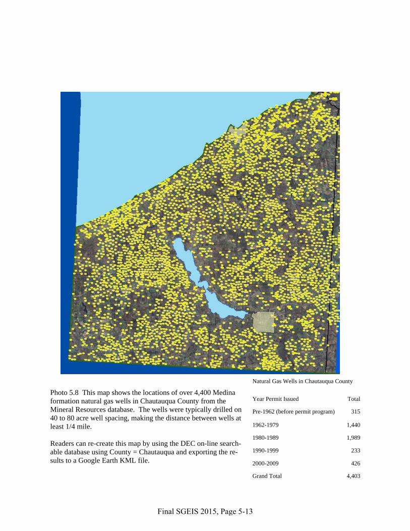
Photo 5.8 This map shows the locations of over 4,400 Medina formation natural gas wells in Chautauqua County from the Mineral Resources database. The wells were typically drilled on 40 to 80 acre well spacing, making the distance between wells at least 1/4 mile.
Readers can re-create this map by using the DEC on-line search-able database using County = Chautauqua and exporting the re-sults to a Google Earth KML file.
Natural Gas Wells in Chautauqua County
Year Permit Issued Total
Pre-1962 (before permit program) 315
1962-1979 1,440
1980-1989 1,989
1990-1999 233
2000-2009 426
Grand Total 4,403
Final SGEIS 2015, Page 5-13

1
Photo 5.9 a & b The above map shows a portion of the Chautauqua County map, near Gerry. Well #1 (API Hole number 25468) shown in the photo to the right was drilled and completed for produc-tion in 2008 to a total depth of 4,095 feet. Of the other 47 Medina gas wells shown above, the nearest is approxi-mately 1,600 feet to the north.
These Medina wells use single well pads. Marcellus multi-well pads will be larger and will have more wellheads and tanks.
1
Final SGEIS 2015, Page 5-14

2
Photo 5.10 a & b This map shows 28 wells in the Town of Poland, Chautauqua County. Well #2 (API Hole number 24422) was drilled in 2006 to a depth of 4,250 feet and completed for production in 2007. The nearest other well is 1,700 feet away.
2
Final SGEIS 2015, Page 5-15

3
Photo 5.11 a & b The map above shows 77 wells. Well #3 (API Hole number 16427) identified in the map above, and shown in the photo below, was completed in the Town of Sheridan, Chautauqua County in 1981 and was drilled to a depth of 2,012 feet. The map indicates that the nearest producing well to Well #3 is 1/4 mile away.
3
Final SGEIS 2015, Page 5-16

Final SGEIS 2015, Page 5-17
Vertical Wells
Statewide spacing for vertical shale wells provides for one well per 40-acre spacing
unit.136 This is the spacing requirement that has historically governed most gas well drilling in
the State, and as mentioned above, many square miles of Chautauqua, Seneca and Cayuga
counties have been developed on this spacing. One well per 40 acres equates to a density of 16
wells per square mile (i.e., 640 acres). Infill wells, resulting in more than one well per 40 acres,
may be drilled upon justification to the Department that they are necessary to efficiently recover
gas reserves. Gas well development on 40-acre spacing, with the possibility of infill wells, has
been the prevalent gas well development method in New York for many decades. However, as
reported by the Ground Water Protection Council,137 economic and technological considerations
favor the use of horizontal drilling for shale gas development. As explained below, horizontal
drilling necessarily results in larger spacing units and reduced well pad density. Industry
estimates that 10% of the wells drilled to develop shale resources by high-volume hydraulic
fracturing will be vertical.138
Horizontal Wells in Single-Well Spacing Units
Statewide spacing for horizontal wells where only one well will be drilled at the surface site
provides for one well per 40 acres plus the necessary and sufficient acreage so that there will be
330 feet between the wellbore in the target formation and the spacing unit boundary. This means
that the width of the spacing unit will be at least 660 feet and the distance within the target
formation between wellbores will also always be at least 660 feet. Surface locations may be
somewhat closer together because of the need to begin building angle in the wellbore about 500
feet above the target formation. However, unless the horizontal length of the wellbores within
the target formation is limited to 1,980 feet, the spacing units will exceed 40 acres in size.
Although it is possible to drill horizontal wellbores of this length, all information provided to
date indicates that, in actual practice, lateral distance drilled will normally exceed 2,000 feet and
as an example would most likely be 4,000 feet or more, requiring substantially more than 40
136 A spacing unit is the geographic area assigned to the well for the purposes of sharing costs and production. ECL §23-0501(2)
requires that the applicant control the oil and gas rights for 60% of the acreage in a spacing unit for a permit to be issued. Uncontrolled acreage is addressed through the compulsory integration process set forth in ECL §23-0901(3).
137 GWPC, April 2009, pp. 46-47. 138 ALL Consulting, 2010, p. 7.

Final SGEIS 2015, Page 5-18
acres. Therefore, the overall density of surface locations would be less than 16 wells per square
mile. For example, with 4,000 feet as the length of a horizontal wellbore in the target shale
formation, a spacing unit would be 4,660 feet long by 660 feet wide, or about 71 acres in size.
Nine, instead of 16, spacing units would fit within a square mile, necessitating nine instead of 16
access roads and nine instead of 16 gas gathering lines. Longer laterals would further reduce the
number of well pads per square mile. The Department anticipates that the vast majority of
horizontal wells will be drilled from common pads (i.e., multi-well pads), reducing surface
disturbance even more.
Horizontal Wells with Multiple Wells Drilled from Common Pads
The third statewide spacing option for shale wells provides, initially, for spacing units of up to
640 acres with all the horizontal wells in the unit drilled from a common well pad. Industry
estimates that 90% of the wells drilled to develop shale resources by high-volume hydraulic
fracturing will be horizontal;139 as stated above, the Department anticipates that the vast majority
of them will be drilled from multi-well pads. This method provides the most flexibility to avoid
environmentally sensitive locations within the acreage to be developed and significantly reduces
the number of needed well pads and associated roads.
With respect to overall land disturbance, the larger surface area of an individual multi-well pad
will be more than offset by the fewer total number of well pads within a given area and the need
for only a single access road and gas gathering system to service multiple wells on a single
pad. Overall, there clearly is a smaller total area of land disturbance associated with horizontal
wells for shale gas development than that for vertical wells.140 For example, a spacing of 40
acres per well for vertical shale gas wells would result in, on average, of 70 – 80 acres of
disturbance for the well pads, access roads and utility corridors (4.8 acres per well141) to develop
an area of 640 acres. By contrast, a single well pad with 6 to 8 horizontal shale gas wells could
access all 640 acres with an average of 7.4 acres of total land disturbance. Table 5.1 below
provides another comparison between the well pad acreage disturbed within a 10-square mile
139 ALL Consulting, 2010, p. 7. 140 Alpha, 2009, p. 6-2. 141 ALL Consulting, 2010, p. 14.

Final SGEIS 2015, Page 5-19
area completely developed by multi-well pad horizontal drilling versus single-well pad vertical
drilling.142
Table 5.1 - Ten square mile area (i.e., 6,400 acres), completely drilled with horizontal wells in multi-well units or vertical wells in single-well units (Updated July 2011)
Spacing Option Multi-Well 640 Acre Single-Well 40 Acre Number of Pads 10 160 Total Disturbance - Drilling Phase 74 Acres
(7.4 acres per pad) 768 Acres
(4.8 ac. per pad) % Disturbance - Drilling Phase 1.2% 12% Total Disturbance - Production Phase 15 Acres
(1.5 ac. per pad) 80 Acres
(0.5 ac. per pad) % Disturbance - Production Phase 0.23% 1.25% It is possible that a single well-pad could be positioned to site wells to reach adjacent units,
thereby developing 1,280 acres or more without increasing the land disturbance described above
for multi-well pads. Use of longer lateral wellbores is another potential method for developing
larger areas with less land disturbance.143
Variances or Non-Conforming Spacing Units
The ECL has always provided for variances from statewide spacing or non-conforming spacing
units, with justification, which could result in a greater well density for any of the above
options. A variance from statewide spacing or a non-conforming spacing unit requires the
Department to issue a well-specific spacing order following public comment and, if necessary,
an adjudicatory hearing. Environmental impacts associated with any well to be drilled under a
particular spacing order will continue to be reviewed separately from the spacing variance upon
receipt of a specific well permit application.
5.2 Horizontal Drilling
The first horizontal well in New York was drilled in 1989, and in 2008 approximately 10% of the
well permit applications received by the Department were for directional or horizontal wells.
The predominant use of horizontal drilling associated with natural gas development in New York 142 NTC, 2009, p. 29, updated with information from ALL Consulting, 2010. 143 ALL Consulting, 2010, p. 87.

Final SGEIS 2015, Page 5-20
has been for production from the Black River and Herkimer Formations during the past several
years. The combination of horizontal drilling and hydraulic fracturing is widely used in other
areas of the United States as a means of recovering gas from tight shale formations.
Except for the use of specialized downhole tools, horizontal drilling is performed using similar
equipment and technology as vertical drilling, with the same protocols in place for aquifer
protection, fluid containment and waste handling. As described below, there are four primary
differences between horizontal drilling for shale gas development and the drilling described in
the 1992 GEIS. One is that larger rigs may be used for all or part of the drilling, with longer per-
well drilling times than were described in the 1992 GEIS. The second is that multiple wells are
likely to be drilled from each well site (or well pad). The third is that drilling mud rather than air
may be used while drilling the horizontal portion of the wellbore to lubricate and cool the drill
bit and to clean the wellbore. Fourth and finally, the volume of rock cuttings returned to the
surface from the target formation will be greater for a horizontal well than for a vertical well.
Vertical drilling depth will vary based on target formation and location within the state. Chapter
5 of the 1992 GEIS discusses New York State’s geology with respect to oil and gas production.
Chapter 4 of this SGEIS expands upon that discussion, with emphasis on the Marcellus and Utica
Shales. Chapter 4 includes maps which show depths and thicknesses related to these two shales.
In general, wells will be drilled vertically to a depth of about 500 feet above the top of a target
interval, such as the Union Springs Member of the Marcellus Shale. Drilling may continue with
the same rig, or a larger drill rig may be brought onto the location to build angle and drill the
horizontal portion of the wellbore. A downhole motor behind the drill bit at the end of the drill
pipe is used to accomplish the angled or directional drilling deep within the earth. The drill pipe
is also equipped with inclination and azimuth sensors located about 60 feet behind the drill bit to
continuously record and report the drill bit’s location.
Current drilling technology for onshore consolidated strata results in maximum lateral lengths
that do not greatly exceed the depth of the well. For example, a 5,000-foot deep well would
generally not have a lateral length of significantly greater than 5,000 feet.144 This may change,
144 ALL Consulting, 2010, pp. 87-88.

Final SGEIS 2015, Page 5-21
however, as drilling technology continues to evolve. The length of the horizontal wellbore can
also be affected by the operator’s lease position or compulsory integration status within the
spacing unit, the configuration of the approved spacing unit and wellbore paths, and other factors
which influence well design.
5.2.1 Drilling Rigs
Wells for shale gas development using high-volume hydraulic fracturing will be drilled with
rotary rigs. Rotary rigs are described in the 1992 GEIS, with the typical rotary rigs used in New
York at the time characterized as either 40 to 45-foot high “singles” or 70 to 80-foot high
“doubles.” These rigs can, respectively, hold upright one joint of drill pipe or two connected
joints. “Triples,” which hold three connected joints of drill pipe upright and are over 100 feet
high, were not commonly used in New York State when the 1992 GEIS was prepared. However,
triples have been more common in New York since 1992 for natural gas storage field drilling and
to drill some Trenton-Black River wells, and may be used for drilling wells in the Marcellus
Shale and other low-permeability reservoirs.
Operators may use one large rig to drill an entire wellbore from the surface to toe of the
horizontal bore, or may use two or three different rigs in sequence. For each well, only one rig is
over the hole at a time. At a multi-well site, two rigs may be present on the pad at once, but
more than two are unlikely because of logistical and space considerations as described below.
When two rigs are used (in sequence) to drill a well, a smaller rig of similar dimensions to the
typical rotary rigs described in the 1992 GEIS would first drill the vertical portion of the well.
Only the rig used to drill the horizontal portion of the well is likely to be significantly larger than
what is described in the 1992 GEIS. This rig may be a triple, with a substructure height of about
20 feet, a mast height of about 150 feet, and a surface footprint with its auxiliary equipment of
about 14,000 square feet. Auxiliary equipment includes various tanks (for water, fuel and
drilling mud), generators, compressors, solids control equipment (shale shaker, de-silter, de-
sander), choke manifold, accumulator, pipe racks and the crew’s office space (dog house). Initial
work with the smaller rig would typically take up to two weeks, followed by another up to two
weeks of work with the larger rig. These estimates include time for casing and cementing the

Final SGEIS 2015, Page 5-22
well, and may be extended if drilling is slower than anticipated because of properties of the rock,
or if other problems or unexpected delays occur.
When three rigs are used to drill a well, the first rig is used to drill, case, and cement the surface
hole. This event generally takes about 8 to12 hours. The dimensions of this rig would be
consistent with what is described in the 1992 GEIS. The second rig for drilling the remainder of
the vertical hole would also be consistent with 1992 GEIS descriptions and would again typically
be working for up to 14 days, or longer if drilling is slow or problems occur. The third rig,
equipped to drill horizontally, would, as noted above, be the only one that might exceed 1992
GEIS dimensions, with a substructure height of about 20 feet, a mast height of about 150 feet,
and a surface footprint with its auxiliary equipment of about 14,000 square feet. Work with this
rig would take up to 14 days, or longer if drilling is slow or other problems or delays occur.
An important component of the drilling rig is the blow-out prevention (BOP) system. This
system is discussed in the 1992 GEIS. In summary, BOP system on a rotary drilling rig is a
pressure control system designed specifically to contain and control a “kick” (i.e., unexpected
pressure resulting in the flow of formation fluids into the wellbore during drilling operations).
Other than the well itself, the BOP system basically consists of four parts: 1) the blow-out
preventer stack, 2) the accumulator unit, 3) the choke manifold, and 4) the kill line. Blow-out
preventers are manually or hydraulically operated devices installed at the top of the surface
casing. Within the blow-out preventer there may be a combination of different types of devices
to seal off the well. Pipe rams contain two metal blocks with semi-circular notches that fit
together around the outside of the drill pipe when it is in the hole to block movement of fluids
around the pipe. Blind rams contain two rubber faced metal blocks that can completely seal off
the hole when there is no drill pipe in it. Annular or "bag" type blowout preventers contain a
resilient packing element which expands inward to seal off the hole with or without drill pipe. In
accordance with 6 NYCRR §554.4, the BOP system must be maintained and in proper working
order during operations. A BOP test program is employed to ensure the BOP system is
functioning properly if and when needed.

Final SGEIS 2015, Page 5-23
Appendix 7 includes sample rig specifications provided by Chesapeake Energy. As noted on the
specs, fuel storage tanks associated with the larger rigs would hold volumes of 10,000 to 12,000
gallons.
In summary, the rig work for a single horizontal well – including drilling, casing and cementing
– would generally last about four to five weeks, subject to extension for slow drilling or other
unexpected problems or delays. A 150-foot tall, large-footprint rotary rig may be used for the
entire duration or only for the actual horizontal drilling. In the latter case, smaller, 1992 GEIS-
consistent rigs would be used to drill the vertical portion of the wellbore. The rig and its
associated auxiliary equipment would typically move off the well before fracturing operations
commence.
Photo 5.12, Photo 5.13, Photo 5.14, and Photo 5.15 are photographs of drilling rigs.
5.2.2 Multi-Well Pad Development
Horizontal drilling from multi-well pads is the common development method employed to
develop Marcellus Shale reserves in the northern tier of Pennsylvania and is expected to be
common in New York as well. In New York, ECL 23 requires that all horizontal wells in a
multi-well shale unit be drilled within three years of the date the first well in the unit commences
drilling, to prevent operators from holding acreage within large spacing units without fully
developing the acreage.145
As described above, the space required for hydraulic fracturing operations for a multi-well pad is
dictated by a number of factors but is expected to most commonly be about 3.5 acres.146 The
well pad is often centered in the spacing unit.
145 ECL §23-0501. 146 Cornue, 2011.

Photo 5.12 Double. Union Drilling Rig 54, Olsen 1B, Town of Fenton, Broome County NY. Credit: NYS DEC 2005.
Photo 5.13 Double. Union Drilling Rig 48. Trenton-Black River well, Salo 1, Town of Barton, Tioga County NY. Source: NYS DEC 2008.
Final SGEIS 2015, Page 5-24

Photo 5.14 Triple. Precision Drilling Rig 26. Ruger 1 well, Horseheads, Chemung County. Credit: NYS DEC 2009.
Photo 5.15 Top Drive Single. Barber and DeLine rig, Sheckells 1, Town of Cherry Valley, Otsego County. Credit: NYS DEC 2007.
Final SGEIS 2015, Page 5-25

Final SGEIS 2015, Page 5-26
Several factors determine the optimal drilling pattern within the target formation. These include
geologic controls such as formation depth and thickness, mechanical and physical factors
associated with the well construction program, production experience in the area, lease position
and topography or surface restrictions that affect the size or placement of pads.147 Often, evenly
spaced parallel horizontal bores are drilled in opposite directions from surface locations arranged
in two parallel rows. When fully developed, the resultant horizontal well pattern underground
could resemble two back-to-back pitchforks [Figure 5.2]. Other, more complex patterns may
also be proposed.
Figure 5.2 - Possible well spacing unit configurations and wellbore paths
Because of the close well spacing at the surface, most operators have indicated that only one
drilling rig at a time would be operating on any given well pad. One operator has stated that on a
well pad where six or more wells are needed, it is possible that two triple-style rigs may operate
concurrently. Efficiency and the economics of mobilizing equipment and crews would dictate
that all wells on a pad be drilled sequentially, during a single mobilization. However, this may
147 ALL Consulting, 2010, p. 88.

Final SGEIS 2015, Page 5-27
be affected by the timing of compulsory integration proceedings if wellbores are proposed to
intersect unleased acreage.148 Other considerations may result in gaps between well drilling
episodes at a well pad. For instance, early development in a given area may consist of initially
drilling and stimulating one to three wells on a pad to test productivity, followed by additional
wells later, but within the required 3-year time frame. As development in a given area matures
and the results become more predictable, the frequency of drilling and completing all the wells
on each pad with continuous activity in a single mobilization would be expected to increase.
5.2.3 Drilling Mud
The vertical portion of each well, including the portion that is drilled through any fresh water
aquifers, will typically be drilled using either compressed air or freshwater mud as the drilling
fluid. Operators who provided responses to the Department’s information requests stated that the
horizontal portion, drilled after any fresh water aquifers have been sealed behind cemented
surface casing, and typically cemented intermediate casing, may be drilled with a mud that may
be (i) water-based, (ii) potassium chloride/polymer-based with a mineral oil lubricant, or (iii)
synthetic oil-based. Synthetic oil-based muds are described as “food-grade” or “environmentally
friendly.” When drilling horizontally, mud is needed for (1) powering and cooling the downhole
motor and bit used for directional drilling, (2) using navigational tools which require mud to
transmit sensor readings, (3) providing stability to the horizontal borehole while drilling and (4)
efficiently removing cuttings from the horizontal hole. Other operators may drill the horizontal
bore “on air,” (i.e., with compressed air) using special equipment to control fluids and gases that
enter the wellbore. Historically, most wells in New York are drilled on air and air drilling is
addressed by the 1992 GEIS.
Drilling mud is contained and managed on-site through the rig’s mud system which is comprised
of a series of piping, separation equipment, and tanks. Photo 5.16 depicts some typical mud-
system components. During drilling or circulating mud is pumped from the mud holding tanks at
the surface down hole through the drill string and out the drill bit, and returns to the surface
through the annular space between the drill string and the walls of the bore hole, where it enters
the flowline and is directed to the separation equipment. Typical separation equipment includes
148 ECL §23-0501 2.b. prohibits the wellbore from crossing unleased acreage prior to issuance of a compulsory integration order.

Final SGEIS 2015, Page 5-28
shale shakers, desanders, desilters and centrifuges which separate the mud from the rock
cuttings. The mud is then re-circulated back into the mud tanks where it is withdrawn by the
mud pump for continued use in the well. As described in the 1992 GEIS, used drilling mud is
typically reconditioned for use at a subsequent well. The subsequent well may be located on the
same well pad or at another location.
Photo 5.16 - Drilling rig mud system (blue tanks)
5.2.4 Cuttings
The rock chips and very fine-grained rock fragments removed by the drilling process and
returned to the surface in the drilling fluid are known as “cuttings” and are contained and
managed either in a lined on-site reserve pit or in a closed-loop tank system.149 As described in
Section 5.13.1, the proper disposal method for cuttings is determined by the composition of the
fluid or fluids used during drilling. The proper disposal method will also dictate how the
cuttings must be contained on-site prior to disposal, as described by Section 7.1.9.
149 Adapted from Alpha, 2009, p. 133.

Final SGEIS 2015, Page 5-29
5.2.4.1 Cuttings Volume
Horizontal drilling penetrates a greater linear distance of rock and therefore produces a larger
volume of drill cuttings than does a well drilled vertically to the same depth below the ground
surface. For example, a vertical well with surface, intermediate and production casing drilled to
a total depth of 7,000 feet produces approximately 154 cubic yards of cuttings, while a
horizontally drilled well with the same casing program to the same target depth with an example
4,000-foot lateral section produces a total volume of approximately 217 cubic yards of cuttings
(i.e., about 40% more). A multi-well site would produce approximately that volume of cuttings
from each well.
5.2.4.2 NORM in Marcellus Cuttings
To determine NORM concentrations and the potential for exposure to NORM contamination in
Marcellus rock cuttings and cores (i.e., continuous rock samples, typically cylindrical, recovered
during specialized drilling operations), the Department conducted field and sample surveys using
portable Geiger counter and gamma ray spectroscopy methods. Gamma ray spectroscopy
analyses were performed on composited Marcellus samples collected from two vertical wells
drilled through the Marcellus, one in Lebanon (Madison County), and one in Bath (Steuben
County). The results of these analyses are presented in Table 5.2a. Department staff also used a
Geiger counter to screen three types of Marcellus samples: cores from the New York State
Museum’s collection in Albany; regional outcrops of the unit; and various Marcellus well sites
from the west-central part of the state, where most of the vertical Marcellus wells in NYS are
currently located. These screening data are presented in Table 5.2b. Additional radiological
analytical data for Marcellus Shale drill cuttings has been reported from Marcellus wells in
Pennsylvania. Samples were collected from loads of drill cuttings being transported for disposal,
as well as directly from the drilling rigs during drilling of the horizontal legs of the wells. The
materials sampled were screened in-situ with a micro R meter, and analyzed by gamma ray
spectroscopy. These data are provided in Table 5.3. As discussed further in Chapter 6, the
results, which indicate levels of radioactivity that are essentially equal to background values, do
not indicate an exposure concern for workers or the general public associated with Marcellus
cuttings.

Final SGEIS 2015, Page 5-30
Table 5.2 - 2009 Marcellus Radiological Data
Table 5.2a Marcellus Radiological Data from Gamma Ray Spectroscopy Analyses Well
(Depth) API # Date Collected Town (County) Parameter Result +/-
Uncertainty
Crouch C 4H (1040 feet - 1115 feet)
31-053-26305-00-00 3/17/09 Lebanon (Madison)
K-40 14.438 +/- 1.727 pCi/g Tl-208 0.197 +/- 0.069 pCi/g Pb-210 2.358 +/- 1.062 pCi/g Bi-212 0.853 +/- 0.114 pCi/g Bi-214 1.743 +/- 0.208 pCi/g Pb-214 1.879 +/- 0.170 pCi/g Ra-226 1.843 +/- 0.573 pCi/g Ac-228 0.850 +/- 0.169 pCi/g Th-234 1.021 +/- 0.412 pCi/g U-235 0.185 +/- 0.083 pCi/g
Blair 2A (2550’ - 2610’)
31-101-02698-01-00 3/26/09 Bath (Steuben)
K-40 22.845 +/- 2.248 pCi/g Tl-208 0.381 +/- 0.065 pCi/g Pb-210 0.535 +/- 0.712 pCi/g Bi-212 1.174 +/- 0.130 pCi/g Bi-214 0.779 +/- 0.120 pCi/g Pb-214 0.868 +/- 0.114 pCi/g Ra-226 0.872 +/- 0.330 pCi/g Ac-228 1.087 +/- 0.161 pCi/g Th-234 0.567 +/- 0.316 pCi/g U-235 0.079 +/- 0.058 pCi/g
Table 5.2b Marcellus Radiological Data from Geiger Counter Screening Media
Screened Well Date Location (County) Results
Cores Beaver Meadow 1 3/12/09 NYS Museum (Albany) 0.005 - 0.080 mR/hr Oxford 1 3/12/09 NYS Museum (Albany) 0.005 - 0.065 mR/hr 75 NY-14 3/12/09 NYS Museum (Albany) 0.015 - 0.065 mR/hr EGSP #4 3/12/09 NYS Museum (Albany) 0.005 - 0.045 mR/hr Jim Tiede 3/12/09 NYS Museum (Albany) 0.005 - 0.025 mR/hr 75 NY-18 3/12/09 NYS Museum (Albany) 0.005 - 0.045 mR/hr 75 NY-12 3/12/09 NYS Museum (Albany) 0.015 - 0.045 mR/hr 75 NY-21 3/12/09 NYS Museum (Albany) 0.005 - 0.040 mR/hr 75 NY-15 3/12/09 NYS Museum (Albany) 0.005 - 0.045 mR/hr Matejka 3/12/09 NYS Museum (Albany) 0.005 - 0.090 mR/hr
Outcrops N/A 3/24/2009 Onesquethaw Creek (Albany) 0.02 - 0.04 mR/hr N/A 3/24/2009 DOT Garage, CR 2 (Albany) 0.01 - 0.04 mR/hr N/A 3/24/2009 SR 20, near SR 166 (Otsego) 0.01 - 0.04 mR/hr N/A 3/24/2009 Richfield Springs (Otsego) 0.01 - 0.06 mR/hr N/A 3/24/2009 SR 20 (Otsego) 0.01 - 0.03 mR/hr N/A 3/24/2009 Gulf Rd (Herkimer) 0.01 - 0.04 mR/hr Well Sites Beagell 2B 4/7/2009 Kirkwood (Broome) 0.04 mR/hr *
Hulsebosch 1 4/2/2009 Elmira City (Chemung) 0.03 mR/hr * Bush S1 4/2/2009 Elmira (Chemung) 0.03 mR/hr *

Final SGEIS 2015, Page 5-31
Parker 1 4/7/2009 Oxford (Chenango) 0.05 mR/hr * Well Sites Donovan Farms 2 3/30/2009 West Sparta (Livingston) 0.03 mR/hr *
Fee 1 3/30/2009 Sparta (Livingston) 0.02 mR/hr * Meter 1 3/30/2009 West Sparta (Livingston) 0.03 mR/hr * Schiavone 2 4/6/2009 Reading (Schuyler) 0.05 mR/hr * WGI 10 4/6/2009 Dix (Schuyler) 0.07 mR/hr * WGI 11 4/6/2009 Dix (Schuyler) 0.07 mR/hr * Calabro T1 3/26/2009 Orange (Schuyler) 0.03 mR/hr * Calabro T2 3/26/2009 Orange (Schuyler) 0.05 mR/hr * Frost 2A 3/26/2009 Orange (Schuyler) 0.05 mR/hr * Webster T1 3/26/2009 Orange (Schuyler) 0.05 mR/hr * Haines 1 4/1/2009 Avoca (Steuben) 0.03 mR/hr * Haines 2 4/1/2009 Avoca (Steuben) 0.03 mR/hr * McDaniels 1A 4/1/2009 Urbana (Steuben) 0.03 mR/hr * Drumm G2 4/1/2009 Bradford (Steuben) 0.07 mR/hr * Hemley G2 3/26/2009 Hornby (Steuben) 0.03 mR/hr * Lancaster M1 3/26/2009 Hornby (Steuben) 0.03 mR/hr * Maxwell 1C 4/2/2009 Caton (Steuben) 0.07 mR/hr * Scudder 1 3/26/2009 Bath (Steuben) 0.03 mR/hr * Blair 2A 3/26/2009 Bath (Steuben) 0.03 mR/hr * Retherford 1 4/1/2009 Troupsburg (Steuben) 0.05 mR/hr * Carpenter 1 4/1/2009 Troupsburg (Steuben) 0.05 mR/hr * Cook 1 4/1/2009 Troupsburg (Steuben) 0.05 mR/hr * Zinck 1 4/1/2009 Woodhull (Steuben) 0.07 mR/hr * Tiffany 1 4/7/2009 Owego (Tioga) 0.03 mR/hr * *maximum values detected
Table 5.3 - Gamma Ray Spectroscopy

Final SGEIS 2015, Page 5-32
5.2.5 Management of Drilling Fluids and Cuttings
The 1992 GEIS discusses the use of reserve pits and tanks, either alone or in conjunction with
one another, to contain the cuttings and fluids associated with the drilling process. Both systems
result in complete capture of the fluids and cuttings; however the use of tanks in closed-loop tank
systems facilitates off-site disposal of wastes while more efficiently utilizing drilling fluid and
providing additional insurance against environmental releases.
5.2.5.1 Reserve Pits on Multi-Well Pads
The 1992 GEIS describes the construction, use and reclamation of lined reserve pits, (also called
“drilling pits” or “mud pits”) to contain cuttings and fluids associated with the drilling process.
Rather than using a separate pit for each well on a multi-well pad, operators may propose to
maintain a single pit on the well pad until all wells are drilled and completed. The pit would
need to be adequately sized to hold cuttings from all the wells, unless the cuttings are removed
intermittently as needed to ensure adequate room for drilling-associated fluids and precipitation.
Under existing regulations, fluid associated with each well would have to be removed within 45
days of the cessation of drilling operations, unless the operator has submitted a plan to use the
fluids in subsequent operations and the Department has inspected and approved the pit.150
Chapter 7 discusses restrictions related to the use of reserve pits for managing drilling fluids and
cuttings for high-volume hydraulic fracturing.
5.2.5.2 Closed-Loop Tank Systems
The design and configuration of closed-loop tank systems will vary from operator to operator,
but all such systems contain drilling fluids and cuttings in a series of containers, thereby
eliminating the need for a reserve pit. The containers may include tanks or bins that may have
closed tops, open tops or open tops in combination with open sides. They may be stationary or
truck-, trailer-, or skid-mounted. Regardless of the specific design of the containers, the
objective is to fully contain the cuttings and fluids in such a manner as to prevent direct contact
with the ground surface or the need to construct a lined reserve pit.
Depending on the drilling fluid utilized, a variety of types of separation equipment may be
employed within a closed-loop tank system to separate the liquids from the cuttings prior to 150 6 NYCRR §554.1(c)(3).

Final SGEIS 2015, Page 5-33
capture within the system’s containers. For air drilling employing a closed-loop tank system,
shale shakers or other gravity-based equipment would likely be utilized to separate any
formation fluids from the cuttings whereas mud drilling would employ equipment which is
virtually identical to that of the drilling mud systems described previously in Section 5.2.3.
In addition to the equipment typically employed in a drilling mud system, operators may elect to
utilize additional solids control equipment within the closed-loop system when drilling on mud,
in an effort to further separate liquids from the cuttings. Such equipment could include but is not
limited to drying shakers, vertical or horizontal rotary cuttings dryers, squeeze presses, or
centrifuges151 and when oil-based drilling muds are utilized the separation process may also
include treatment to reduce surface tension between the mud and the cuttings.152,153 The
additional separation results in greater recovery of the drilling mud for re-circulation and
produces dryer cuttings for off-site disposal.
Depending on the moisture-content of the cuttings, operators may drain or vacuum free-liquids
from the cuttings container, or they may mix absorbent agents such as lime, saw dust or wood
chips into the cuttings in order to absorb any free-liquids prior to hauling off-site for disposal.
This mixing may take place in the primary capture container where the cuttings are initially
collected following separation or in a secondary container located on the well pad.
Operators may simply employ primary capture containers which are suitable for capturing and
transporting cuttings from the well site, or they may transfer cuttings from the primary capture
container to a secondary capture container for transport purposes. If cuttings will be transferred
between containers, front end loaders, vacuum trucks or other equipment would be utilized and
all transfers will be required to occur in a designated transfer area on the well pad, which will be
required to be lined.
151 ANL, 2011(a). 152 The American Oil & Gas Reporter, August 2010, p. 92-93. 153 Dugan, April 2008.

Final SGEIS 2015, Page 5-34
Depending on the configuration and design of a closed-loop tank system use of such a system
can offer the following advantages:
• Eliminates the time and expense associated with reserve pit construction and reclamation;
• Reduces the surface disturbance associated with the well pad;
• Reduces the amount of water and mud additives required as a result of re-circulation of drilling mud;
• Lowers mud replacement costs by capturing and re-circulating drilling mud;
• Reduces the wastes associated with drilling by separating additional drilling mud from the cuttings; and
• Reduces expenses and truck traffic associated with transporting drilling waste due to the reduced volume of the waste.
5.3 Hydraulic Fracturing
The 1992 GEIS discusses, in Chapter 9, hydraulic fracturing operations using water-based gel
and foam, and describes the use of water, hydrochloric acid and additives including surfactants,
bactericides,154 clay and iron inhibitors and nitrogen. The fracturing fluid is an engineered
product; service providers vary the design of the fluid based on the characteristics of the
reservoir formation and the well operator’s objectives. In the late 1990s, operators and service
companies in other states developed a technology known as “slickwater fracturing” to develop
shale formations, primarily by increasing the amount and proportion of water used, reducing the
use of gelling agents and adding friction reducers. Any fracturing fluid may also contain scale
and corrosion inhibitors.
ICF International, which reviewed the current state of practice of hydraulic fracturing under
contract with NYSERDA, states that the development of water fracturing technologies has
reduced the quantity of chemicals required to hydraulically fracture target reservoirs and that
154 Bactericides must be registered for use in New York in accordance with ECL §33-0701. Well operators, service companies,
and chemical supply companies were reminded of this requirement in an October 28, 2008 letter from the Division of Mineral Resources formulated in consultation with the former Division of Solid and Hazardous Materials, now Materials Management. This correspondence also reminded industry of the corresponding requirement that all bactericides be properly labeled and that the labels for such products be kept on-site during application and storage.

Final SGEIS 2015, Page 5-35
slickwater treatments have yielded better results than gel treatments in the Barnett Shale.155 Poor
proppant suspension and transport characteristics of water versus gel are overcome by the low
permeability of shale formations which allow the use of finer-grained proppants and lower
proppant concentrations.156 The use of friction reducers in slickwater fracturing procedures
reduce the required pumping pressure at the surface, thereby reducing the number and power of
pumping trucks needed.157 In addition, according to ICF, slickwater fracturing causes less
formation damage than other techniques such as gel fracturing.158
Both slickwater fracturing and foam fracturing have been proposed for Marcellus Shale
development. As foam fracturing is already addressed by the 1992 GEIS, this document focuses
on slickwater fracturing. This type of hydraulic fracturing is referred to herein as “high-volume
hydraulic fracturing” because of the large water volumes required.
5.4 Fracturing Fluid
The fluid used for slickwater fracturing is typically comprised of more than 98% fresh water and
sand, with chemical additives comprising 2% or less of the fluid.159 The Department has
collected compositional information on many of the additives proposed for use in fracturing
shale formations in New York directly from chemical suppliers and service companies. This
information has been evaluated by the Department’s Division of Air Resources (DAR) and
DOW as well as the NYSDOH’s Bureaus of Water Supply Protection and Toxic Substances
Assessment. It has also been reviewed by technical consultants contracted by NYSERDA160 to
conduct research related to the preparation of this document. Discussion of potential
environmental impacts and mitigation measures in Chapters 6 and 7 of this SGEIS reflect
analysis and input by all of the foregoing entities.
155 ICF Task 1, 2009. pp. 10, 19. 156 ICF Task 1, 2009. pp. 10, 19. 157 ICF Task 1, 2009. P. 12. 158 ICF Task 1, 2009. P. 19. 159 GWPC, April 2009, pp. 61-62. 160 Alpha Environmental Consultants, Inc., ICF International, URS Corporation.
Final SGEIS 2015, Page 5-36
Six service companies161 and 15 chemical suppliers162 have provided additive product
compositional information to the Department in the form of product Material Safety Data Sheets
(MSDSs)163 and product composition disclosures consisting of chemical constituent names and
their associated Chemical Abstract Service (CAS) Numbers,164 as well as chemical constituent
percent by weight information. Altogether, some compositional information is on file with the
Department for 235 products, with complete165 product composition disclosures and MSDSs on
file for 167 of those products. Within these products are 322 unique chemicals whose CAS
Numbers have been disclosed to the Department and at least 21 additional compounds whose
CAS Numbers have not been disclosed due to the fact that many are mixtures. Table 5.4 is an
alphabetical list of all products for which complete chemical information, including complete
product composition disclosures and MSDSs, has been provided to the Department. Table 5.5 is
an alphabetical list of products for which only partial chemical composition information has been
provided to the Department, either in the form of product MSDSs or product composition
disclosures which appear to be lacking information. Any product whose name does not appear
within Table 5.4 or Table 5.5 was not evaluated in this SGEIS either because no chemical
information was submitted to the Department or because the product has not been proposed for
use in high-volume hydraulic fracturing operations in New York to date. These tables are
included for informational purposes only and are not intended to restrict the proposal of
additional additive products. See Chapter 8, Section 8.2.1.1 for a description of the permitting
requirements related to fracturing additive information.
161 BJ Services, Frac Tech Services, Halliburton, Superior Well Services, Universal Well Services, Schlumberger. 162 Baker Petrolite, CESI/Floteck, Champion Technologies/Special Products, Chem EOR, Cortec, Fleurin Fragrances, Industrial
Compounding, Kemira, Nalco, PfP Technologies, SNF Inc., Stepan Company, TBC-Brinadd/Texas United Chemical, Weatherford/Clearwater, and WSP Chemicals & Technology.
163 MSDSs are regulated by the Occupational Safety and Health Administration (OSHA)’s Hazard Communication Standard, 29 CFR 1910.1200(g) and are described in Chapter 8.
164 Chemical Abstracts Service (CAS) is a division of the American Chemical Society. CAS assigns unique numerical identifiers to every chemical described in the literature. The intention is to make database searches more convenient, as chemicals often have many names.
165 The Department defines a complete product composition disclosure to include the chemical names and associated CAS Numbers of every constituent within a product, as well as the percent by weight information associated with each constituent of a product.

Final SGEIS 2015, Page 5-37
Table 5.4 - Fracturing Additive Products – Complete Composition Disclosure Made to the Department (Updated July 2011)
Product Name ABF Acetic Acid 0.1-10% Acid Pensurf / Pensurf Activator W AGA 150 / Super Acid Gell 150 AI-2 Aldacide G Alpha 125 Ammonium Persulfate/OB Breaker APB-1, Ammonium Persulfate Breaker AQF-2 ASP-820 B315 / Friction Reducer B315 B317 / Scale Inhibitor B317 B859 / EZEFLO Surfactant B859 / EZEFLO F103 Surfactant B867 / Breaker B867 / Breaker J218 B868 / EB-CLEAN B868 LT Encapsulated Breaker / EB-Clean J479 LT Encapsulated Breaker B875 / Borate Crosslinker B875 / Borate Crosslinker J532 B880 / EB-CLEAN B880 Breaker / EB-CLEAN J475 Breaker B890 / EZEFLO Surfactant B890 / EZEFLO F100 Surfactant B900 / EZEFLO Surfactant B900/ EZEFLO F108 Surfactant B910 / Corrosion Inhibitor B910 / Corrosion Inhibitor A264 B916 / Gelling Agent ClearFRAC XT B916 / Gelling Agent ClearFRAC XT J590 BA-2 BA-20 BA-40L BA-40LM BC-140 BC-140 X2 BE-3S BE-6 BE-7 BE-9 BF-1 BF-7 / BF-7L BioClear 1000 / Unicide 1000 Bio-Clear 200 / Unicide 2000

Final SGEIS 2015, Page 5-38
Product Name Breaker FR BXL-2, Crosslinker/ Buffer BXL-STD / XL-300MB Carbon Dioxide CC-302T CI-14 CL-31 CLA-CHEK LP Claproteck CF CLA-STA XP Clay Treat PP Clay Treat TS Clay Treat-3C Clayfix II Clayfix II plus CPF-X Plus Cronox 245 ES CS-250 SI CS-650 OS, Oxygen Scavenger CS-Polybreak 210 CS-Polybreak 210 Winterized CT-ARMOR EB-4L Enzyme G-NE FAC-1W / Petrostep FAC-1W FAC-3W / Petrostop FAC-3W FE-1A FE-2 FE-2A FE-5A Ferchek Ferchek A Ferrotrol 300L Flomax 50 Flomax 70 / VX9173 FLOPAM DR-6000 / DR-6000 FLOPAM DR-7000 / DR-7000 Formic Acid FR-46 FR-48W

Final SGEIS 2015, Page 5-39
Product Name FR-56 FRP-121 FRW-14 GasPerm 1000 GBL-8X / LEB-10X / GB-L / En-breaker GBW-30 Breaker Green-Cide 25G / B244 / B244A H015 / Hydrochloric Acid 15% H15 HAI-OS Acid Inhibitor HC-2 High Perm SW-LB HPH Breaker HPH foamer Hydrochloric Acid Hydrochloric Acid (HCl) Hydrochloric Acid 10.1-15% HYG-3 IC 100L ICA-720 / IC-250 ICA-8 / IC-200 ICI-3240 Inflo-250 InFlo-250W / InFlo-250 Winterized Iron Check / Iron Chek Iron Sta IIC / Iron Sta II Isopropyl Alcohol J313 / Water Friction-Reducing Agent J313 J534 / Urea Ammonium Nitrate Solution J534 J580 / Water GellingAgent J580 K-34 K-35 KCI L058 / Iron Stabilizer L58 L064 / Temporary Clay Stabilizer L64 LGC-35 CBM LGC-36 UC LGC-VI UC Losurf 300M M003 / Soda Ash M3 MA-844W

Final SGEIS 2015, Page 5-40
Product Name Methanol MO-67 Morflo III MSA-II Muriatic Acid 36% Musol A N002 / Nitrogen N2 NCL-100 Nitrogen Nitrogen, Liquid N2 OptiKleen-WF Para Clear D290 / ParaClean II Paragon 100 E+ Parasperse Parasperse Cleaner PSI-720 PSI-7208 Salt SAS-2 Scalechek LP-55 Scalechek LP-65 Scalechek SCP-2 / SCP-2 Scalehib 100 / Super Scale Inhibitor / Scale Clear SI-112 SGA II Shale Surf 1000 Shale Surf 1000 Winterized SI 103 Sodium Citrate SP Breaker STIM-50 / LT-32 Super OW 3 Super Pen 2000 SuperGel 15 U042 / Chelating Agent U42 U066 / Mutual Solvent U66
Unicide 100 / EC6116A
Unifoam Unigel 5F UniHibA / SP-43X UnihibG / S-11

Final SGEIS 2015, Page 5-41
Product Name Unislik ST 50 / Stim Lube Vicon NF WG-11 WG-17 WG-18 WG-35 WG-36 WLC-6 XL-1 XL-8 XLW-32 Xylene

Final SGEIS 2015, Page 5-42
Table 5.5 - Fracturing Additive Products – Partial Composition Disclosure to the Department (Updated July 2011)
Product Name 20 Degree Baume Muriatic Acid AcTivator / 78-ACTW AMB-100 B869 / Corrosion Inhibitor B869 / Corrosion Inhibitor A262 B885 / ClearFRAC LT B885 / ClearFRAC LT J551A B892 / EZEFLO B892 / EZEFLO F110 Surfactant CL-22UC CL-28M Clay Master 5C Corrosion Inhibitor A261 FAW- 5 FDP-S798-05 FDP-S819-05 FE ACID FR-48 FRW-16 FRW-18 Fracsal FR-143 Fracsal III Fracsal NE-137 Fracsal Ultra Fracsal Ultra-FM1 Fracsal Ultra-FM2 Fracsal Ultra-FM3 Fracsal Waterbase Fracsal Waterbase-M1 FRW-25M GA 8713 GBW-15L GW-3LDF HVG-1, Fast Hydrating Guar Slurry ICA 400 ICP-1000 Inflo-102 Inhibisal Ultra CS-135 Inhibisal Ultra SI-141 J134L / Enzyme Breaker J134L KCLS-2, KCL Substitute

Final SGEIS 2015, Page 5-43
Product Name L065 / Scale Inhibitor L065 LP-65 Magnacide 575 Microbiocide MSA ACID Multifunctional Surfactant F105 Nitrogen, Refrigerated Liquid Product 239 PS 550 S-150 SandWedge WF SilkWater FR-A Super TSC / Super Scale Control TSC Super Sol 10/20/30 Ultra Breake-C Ultra Breake-CG Ultra Breake-M Ultra-Breake-MG Unislick 30 / Cyanaflo 105L WC-5584 WCS 5177 Corrosion Scale Inhibitor WCW219 Combination Inhibitor WF-12B Foamer WF-12B Salt Inhibitor Stix WF-12B SI Foamer/Salt Inhibitor WF12BH Foamer WRR-5 WFR-C XLBHT-1 XLBHT-2

Final SGEIS 2015, Page 5-44
Information in sections 5.4.1-3 below was compiled primarily by URS Corporation,166 under
contract to NYSERDA.
5.4.1 Properties of Fracturing Fluids
Additives are used in hydraulic fracturing operations to elicit certain properties and
characteristics that would aide and enhance the operation. The desired properties and
characteristics include:
• Non-reactive;
• Non-flammable;
• Minimal residuals;
• Minimal potential for scale or corrosion;
• Low entrained solids;
• Neutral pH (pH 6.5 – 7.5) for maximum polymer hydration;
• Limited formation damage;
• Appropriately modify properties of water to carry proppant deep into the shale;
• Economical to modify fluid properties; and
• Minimal environmental effects.
5.4.2 Classes of Additives
Table 5.6 lists the types, purposes and examples of additives that have been proposed to date for
use in hydraulic fracturing of gas wells in New York State.
166 URS, 2011, p. 2-1 & 2009, p. 2-1.

Final SGEIS 2015, Page 5-45
Table 5.6 - Types and Purposes of Additives Proposed for Use in New York State (Updated July 2011)
Additive Type Description of Purpose Examples of Chemicals167 Proppant “Props” open fractures and allows gas / fluids to flow
more freely to the well bore. Sand [Sintered bauxite; zirconium oxide; ceramic beads]
Acid Removes cement and drilling mud from casing perforations prior to fracturing fluid injection, and provides accessible path to formation.
Hydrochloric acid (HCl, 3% to 28%) or muriatic acid
Breaker Reduces the viscosity of the fluid in order to release proppant into fractures and enhance the recovery of the fracturing fluid.
Peroxydisulfates
Bactericide / Biocide / Antibacterial Agent
Inhibits growth of organisms that could produce gases (particularly hydrogen sulfide) that could contaminate methane gas. Also prevents the growth of bacteria which can reduce the ability of the fluid to carry proppant into the fractures.
Gluteraldehyde; 2,2-dibromo-3-nitrilopropionamide
Buffer / pH Adjusting Agent
Adjusts and controls the pH of the fluid in order to maximize the effectiveness of other additives such as crosslinkers
Sodium or potassium carbonate; acetic acid
Clay Stabilizer / Control /KCl
Prevents swelling and migration of formation clays which could block pore spaces thereby reducing permeability.
Salts (e.g., tetramethyl ammonium chloride Potassium chloride (KCl)
Corrosion Inhibitor (including Oxygen Scavengers)
Reduces rust formation on steel tubing, well casings, tools, and tanks (used only in fracturing fluids that contain acid).
Methanol; ammonium bisulfate for Oxygen Scavengers
Crosslinker Increases fluid viscosity using phosphate esters combined with metals. The metals are referred to as crosslinking agents. The increased fracturing fluid viscosity allows the fluid to carry more proppant into the fractures.
Potassium hydroxide; borate salts
Friction Reducer Allows fracture fluids to be injected at optimum rates and pressures by minimizing friction.
Sodium acrylate-acrylamide copolymer; polyacrylamide (PAM); petroleum distillates
Gelling Agent Increases fracturing fluid viscosity, allowing the fluid to carry more proppant into the fractures.
Guar gum; petroleum distillates
Iron Control Prevents the precipitation of metal oxides which could plug off the formation.
Citric acid;
Scale Inhibitor Prevents the precipitation of carbonates and sulfates (calcium carbonate, calcium sulfate, barium sulfate) which could plug off the formation.
Ammonium chloride; ethylene glycol;
Solvent Additive which is soluble in oil, water & acid-based treatment fluids which is used to control the wettability of contact surfaces or to prevent or break emulsions
Various aromatic hydrocarbons
Surfactant Reduces fracturing fluid surface tension thereby aiding fluid recovery.
Methanol; isopropanol; ethoxylated alcohol
167 Chemicals in brackets [ ] have not been proposed for use in the State of New York to date, but are known to be used in other
states or shale formations.

Final SGEIS 2015, Page 5-46
5.4.3 Composition of Fracturing Fluids
The composition of the fracturing fluid used may vary from one geologic basin or formation to
another or from one area to another in order to meet the specific needs of each operation; but the
range of additive types available for potential use remains the same. There are a number of
different products for each additive type; however, only one product of each type is typically
utilized in any given hydraulic fracturing job. The selection may be driven by the formation and
potential interactions between additives. Additionally not all additive types will be utilized in
every fracturing job.
Sample compositions, by weight, of fracturing fluid are provided in Figure 5.3, Figure 5.4 and
Figure 5.5. The composition depicted in Figure 5.3 is based on data from the Fayetteville
Shale168while those depicted in Figure 5.4 and Figure 5.5 are based on data from Marcellus
Shale development in Pennsylvania. Based on this data, between approximately 84 and 90
percent of the fracturing fluid is water; between approximately 8 and 15 % is proppant (Photo
5.17); the remainder, typically less than 1 % consists of chemical additives listed above.
Barnett Shale is considered to be the first instance of extensive high-volume hydraulic fracturing
technology use; the technology has since been applied in other areas such as the Fayetteville
Shale and the Haynesville Shale. URS notes that data collected from applications to drill
Marcellus Shale wells in New York indicate that the typical fracture fluid composition for
operations in the Marcellus Shale is similar to the provided composition in the Fayetteville
Shale. Even though no horizontal wells have been drilled in the Marcellus Shale in New York,
applications filed to date as well as information provided by the industry169 indicate that it is
realistic to expect that the composition of fracture fluids used in the Marcellus Shale in New
York would be similar to the fluids used in the Fayetteville Shale and the Marcellus Shale in
Pennsylvania.
168 Similar to the Marcellus Shale, the Fayetteville Shale is a marine shale rich in unoxidized carbon (i.e. a black shale). The two
shales are at similar depths, and vertical and horizontal wells have been drilled/fractured at both shales. 169 ALL Consulting, 2010, p. 80.

Final SGEIS 2015, Page 5-47
Photo 5.17 - Sand used as proppant in hydraulic fracturing operation in Bradford County, PA
Figure 5.3 - Sample Fracturing Fluid Composition (12 Additives), by Weight, from Fayetteville Shale170
170 URS, 2009, p. 2-4.
Other, 0.44%
Scale Inhibitor, 0.04%
Surfactant, 0.08%
pH Adjusting Agent, 0.01%
Acid, 0.11%
Breaker, 0.01%
Bactericide/Biocide, 0.001%
Corrosion Inhibitor, 0.001%
Crosslinker, 0.01%
Iron Control, 0.004%
Gelling Agent, 0.05%
Clay Stabilizer/Controler, 0.05%
Friction Reducer, 0.08%
Water, 90.60%
Proppant, 8.96%

Final SGEIS 2015, Page 5-48
Figure 5.4 - Sample Fracturing Fluid Composition (9 Additives), by Weight, from Marcellus Shale171 (New July 2011)
Figure 5.5 - Sample Fracturing Fluid Composition (6 Additives), by Weight, from Marcellus Shale172 (New July 2011)
171 URS, 2011, p. 2-4, adapted from ALL Consulting, 2010, p.81. 172 URS, 2011, p.2-5, adapted from ALL Consulting, 2010, p. 81.

Final SGEIS 2015, Page 5-49
Each product within the 13 classes of additives may be made up of one or more chemical
constituents. Table 5.7 is a list of chemical constituents and their CAS numbers, that have been
extracted from product composition disclosures and MSDSs submitted to the Department for 235
products used or proposed for use in hydraulic fracturing operations in the Marcellus Shale in
New York. It is important to note that several manufacturers/suppliers provide similar products
(i.e., chemicals that would serve the same purpose) for any class of additive, and that not all
types of additives are used in a single well.
Data provided to the Department to date indicates similar fracturing fluid compositions for
vertically and horizontally drilled wells.
Table 5.7 - Chemical Constituents in Additives173,174,175 (Updated July 2011)
CAS Number176 Chemical Constituent 106-24-1 (2E)-3,7-dimethylocta-2,6-dien-1-ol
67701-10-4 (C8-C18) and (C18) Unsaturated Alkylcarboxylic Acid Sodium Salt 2634-33-5 1,2 Benzisothiazolin-2-one / 1,2-benzisothiazolin-3-one
95-63-6 1,2,4 trimethylbenzene 93858-78-7 1,2,4-Butanetricarboxylicacid, 2-phosphono-, potassium salt
123-91-1 1,4 Dioxane 3452-07-1 1-eicosene 629-73-2 1-hexadecene 104-46-1 1-Methoxy-4-propenylbenzene 124-28-7 1-Octadecanamine, N, N-dimethyl- / N,N-Dimthyloctadecylamine
112-03-8 1-Octadecanaminium, N,N,N-Trimethyl-, Chloride /Trimethyloctadecylammonium chloride
112-88-9 1-octadecene 40623-73-2 1-Propanesulfonic acid
1120-36-1 1-tetradecene 95077-68-2 2- Propenoic acid, homopolymer sodium salt
173 Table 5.7, is a list of chemical constituents and their CAS numbers that have been extracted from product composition
disclosures and MSDSs submitted to the Department. It was compiled by URS Corporation (2011) and was adapted by the Department to ensure that it accurately reflects the data submitted.
174 These are the chemical constituents of all chemical additives proposed to be used in New York for hydraulic fracturing operations at shale wells. Only a few chemicals would be used in a single well; the list of chemical constituents used in an individual well would be correspondingly smaller.
175 This list does not include chemicals that are exclusively used for drilling. 176 Chemical Abstracts Service (CAS) is a division of the American Chemical Society. CAS assigns unique numerical identifiers
to every chemical described in the literature. The intention is to make database searches more convenient, as chemicals often have many names. Almost all molecule databases today allow searching by CAS number.

Final SGEIS 2015, Page 5-50
CAS Number176 Chemical Constituent 98-55-5 2-(4-methyl-1-cyclohex-3-enyl)propan-2-ol
10222-01-2 2,2 Dibromo-3-nitrilopropionamide 27776-21-2 2,2'-azobis-{2-(imidazlin-2-yl)propane}-dihydrochloride 73003-80-2 2,2-Dobromomalonamide 15214-89-8 2-Acrylamido-2-methylpropanesulphonic acid sodium salt polymer 46830-22-2 2-acryloyloxyethyl(benzyl)dimethylammonium chloride
52-51-7 2-Bromo-2-nitro-1,3-propanediol 111-76-2 2-Butoxy ethanol / Ethylene glycol monobutyl ether / Butyl Cellusolve
1113-55-9 2-Dibromo-3-Nitriloprionamide /2-Monobromo-3-nitriilopropionamide 104-76-7 2-Ethyl Hexanol 67-63-0 2-Propanol / Isopropyl Alcohol / Isopropanol / Propan-2-ol
26062-79-3 2-Propen-1-aminium, N,N-dimethyl-N-2-propenyl-chloride, homopolymer 9003-03-6 2-propenoic acid, homopolymer, ammonium salt
25987-30-8 2-Propenoic acid, polymer with 2 p-propenamide, sodium salt / Copolymer of acrylamide and sodium acrylate
71050-62-9 2-Propenoic acid, polymer with sodium phosphinate (1:1) 66019-18-9 2-propenoic acid, telomer with sodium hydrogen sulfite
107-19-7 2-Propyn-1-ol / Progargyl Alcohol 51229-78-8 3,5,7-Triaza-1-azoniatricyclo[3.3.1.13,7]decane, 1-(3-chloro-2-propenyl)-
chloride, 106-22-9 3,7 - dimethyl-6-octen-1-ol
5392-40-5 3,7- dimethyl-2,6-octadienal 115-19-5 3-methyl-1-butyn-3-ol 104-55-2 3-phenyl-2-propenal 127-41-3 4-(2,6,6-trimethyl-1-cyclohex-2-enyl)-3-buten-2-one 121-33-5 4-hydroxy-3-methoxybenzaldehyde
127087-87-0 4-Nonylphenol Polyethylene Glycol Ether Branched / Nonylphenol ethoxylated / Oxyalkylated Phenol
64-19-7 Acetic acid 68442-62-6 Acetic acid, hydroxy-, reaction products with triethanolamine
108-24-7 Acetic Anhydride 67-64-1 Acetone 79-06-1 Acrylamide
38193-60-1 Acrylamide - sodium 2-acrylamido-2-methylpropane sulfonate copolymer 25085-02-3 Acrylamide - Sodium Acrylate Copolymer / Anionic Polyacrylamide / 2-
Propanoic Acid 69418-26-4 Acrylamide polymer with N,N,N-trimethyl-2[1-oxo-2-propenyl]oxy
Ethanaminium chloride / Ethanaminium, N, N, N-trimethyl-2-[(1-oxo-2-propenyl)oxy]-, chloride, polymer with 2-propenamide (9Cl)
68891-29-2 Alcohols C8-10, ethoxylated, monoether with sulfuric acid, ammonium salt 68526-86-3 Alcohols, C11-14-iso, C13-rich 68551-12-2 Alcohols, C12-C16, Ethoxylated / Ethoxylated alcohol 64742-47-8 Aliphatic Hydrocarbon / Hydrotreated light distillate / Petroleum Distillates /
Isoparaffinic Solvent / Paraffin Solvent / Napthenic Solvent 64743-02-8 Alkenes

Final SGEIS 2015, Page 5-51
CAS Number176 Chemical Constituent 68439-57-6 Alkyl (C14-C16) olefin sulfonate, sodium salt
9016-45-9 Alkylphenol ethoxylate surfactants 1327-41-9 Aluminum chloride
68155-07-7 Amides, C8-18 and C19-Unsatd., N,N-Bis(hydroxyethyl) 73138-27-9 Amines, C12-14-tert-alkyl, ethoxylated 71011-04-6 Amines, Ditallow alkyl, ethoxylated 68551-33-7 Amines, tallow alkyl, ethoxylated, acetates
1336-21-6 Ammonia 631-61-8 Ammonium acetate
68037-05-8 Ammonium Alcohol Ether Sulfate 7783-20-2 Ammonium bisulfate
10192-30-0 Ammonium Bisulphite 12125-02-9 Ammonium Chloride
7632-50-0 Ammonium citrate 37475-88-0 Ammonium Cumene Sulfonate
1341-49-7 Ammonium hydrogen-difluoride 6484-52-2 Ammonium nitrate 7727-54-0 Ammonium Persulfate / Diammonium peroxidisulphate 1762-95-4 Ammonium Thiocyanate
12174-11-7 Attapulgite Clay 121888-68-4 Bentonite, benzyl(hydrogenated tallow alkyl) dimethylammonium stearate
complex / organophilic clay 71-43-2 Benzene
119345-04-9 Benzene, 1,1'-oxybis, tetratpropylene derivatives, sulfonated, sodium salts 74153-51-8 Benzenemethanaminium, N,N-dimethyl-N-[2-[(1-oxo-2-propenyl)oxy]ethyl]-
, chloride, polymer with 2-propenamide 122-91-8 Benzenemethanol,4-methoxy-, 1-formate
1300-72-7 Benzenesulfonic acid, Dimethyl-, Sodium salt /Sodium xylene sulfonate 140-11-4 Benzyl acetate 76-22-2 Bicyclo (2.2.1) heptan-2-one, 1,7,7-trimethyl-
68153-72-0 Blown lard oil amine 68876-82-4 Blown rapeseed amine
1319-33-1 Borate Salt 10043-35-3 Boric acid
1303-86-2 Boric oxide / Boric Anhydride 71-36-3 Butan-1-ol
68002-97-1 C10 - C16 Ethoxylated Alcohol 68131-39-5 C12-15 Alcohol, Ethoxylated
1317-65-3 Calcium Carbonate 10043-52-4 Calcium chloride
1305-62-0 Calcium Hydroxide 1305-79-9 Calcium Peroxide 124-38-9 Carbon Dioxide
68130-15-4 Carboxymethylhydroxypropyl guar

Final SGEIS 2015, Page 5-52
CAS Number176 Chemical Constituent 9012-54-8 Cellulase / Hemicellulase Enzyme 9004-34-6 Cellulose
10049-04-4 Chlorine Dioxide 78-73-9 Choline Bicarbonate 67-48-1 Choline Chloride 91-64-5 Chromen-2-one 77-92-9 Citric Acid
94266-47-4 Citrus Terpenes 61789-40-0 Cocamidopropyl Betaine 68155-09-9 Cocamidopropylamine Oxide 68424-94-2 Coco-betaine
7758-98-7 Copper (II) Sulfate 14808-60-7 Crystalline Silica (Quartz)
7447-39-4 Cupric chloride dihydrate 1490-04-6 Cyclohexanol,5-methyl-2-(1-methylethyl) 8007-02-1 Cymbopogon citratus leaf oil 8000-29-1 Cymbopogon winterianus jowitt oil 1120-24-7 Decyldimethyl Amine 2605-79-0 Decyl-dimethyl Amine Oxide 3252-43-5 Dibromoacetonitrile
25340-17-4 Diethylbenzene 111-46-6 Diethylene Glycol
22042-96-2 Diethylenetriamine penta (methylenephonic acid) sodium salt 28757-00-8 Diisopropyl naphthalenesulfonic acid 68607-28-3 Dimethylcocoamine, bis(chloroethyl) ether, diquaternary ammonium salt
7398-69-8 Dimethyldiallylammonium chloride 25265-71-8 Dipropylene glycol 34590-94-8 Dipropylene Glycol Methyl Ether
139-33-3 Disodium Ethylene Diamine Tetra Acetate 64741-77-1 Distillates, petroleum, light hydrocracked
5989-27-5 D-Limonene 123-01-3 Dodecylbenzene
27176-87-0 Dodecylbenzene sulfonic acid 42504-46-1 Dodecylbenzenesulfonate isopropanolamine
50-70-4 D-Sorbitol / Sorbitol 37288-54-3 Endo-1,4-beta-mannanase, or Hemicellulase
149879-98-1 Erucic Amidopropyl Dimethyl Betaine 89-65-6 Erythorbic acid, anhydrous
54076-97-0 Ethanaminium, N,N,N-trimethyl-2-[(1-oxo-2-propenyl)oxy]-, chloride, homopolymer
107-21-1 Ethane-1,2-diol / Ethylene Glycol 111-42-2 Ethanol, 2,2-iminobis-
26027-38-3 Ethoxylated 4-nonylphenol 9002-93-1 Ethoxylated 4-tert-octylphenol

Final SGEIS 2015, Page 5-53
CAS Number176 Chemical Constituent 68439-50-9 Ethoxylated alcohol
126950-60-5 Ethoxylated alcohol 67254-71-1 Ethoxylated alcohol (C10-12) 68951-67-7 Ethoxylated alcohol (C14-15) 68439-46-3 Ethoxylated alcohol (C9-11) 66455-15-0 Ethoxylated Alcohols 84133-50-6 Ethoxylated Alcohols (C12-14 Secondary) 68439-51-0 Ethoxylated Alcohols (C12-14) 78330-21-9 Ethoxylated branch alcohol 34398-01-1 Ethoxylated C11 alcohol 78330-21-8 Ethoxylated C11-14-iso, C13-rich alcohols 61791-12-6 Ethoxylated Castor Oil 61791-29-5 Ethoxylated fatty acid, coco 61791-08-0 Ethoxylated fatty acid, coco, reaction product with ethanolamine 68439-45-2 Ethoxylated hexanol
9036-19-5 Ethoxylated octylphenol 9005-67-8 Ethoxylated Sorbitan Monostearate 9005-70-3 Ethoxylated Sorbitan Trioleate
64-17-5 Ethyl alcohol / ethanol 100-41-4 Ethyl Benzene 93-89-0 Ethyl benzoate 97-64-3 Ethyl Lactate
9003-11-6 Ethylene Glycol-Propylene Glycol Copolymer (Oxirane, methyl-, polymer with oxirane)
75-21-8 Ethylene oxide 5877-42-9 Ethyloctynol 8000-48-4 Eucalyptus globulus leaf oil
61790-12-3 Fatty Acids 68604-35-3 Fatty acids, C 8-18 and C18-unsaturated compounds with diethanolamine 68188-40-9 Fatty acids, tall oil reaction products w/ acetophenone, formaldehyde &
thiourea 9043-30-5 Fatty alcohol polyglycol ether surfactant 7705-08-0 Ferric chloride 7782-63-0 Ferrous sulfate, heptahydrate
50-00-0 Formaldehyde 29316-47-0 Formaldehyde polymer with 4,1,1-dimethylethyl phenolmethyl oxirane
153795-76-7 Formaldehyde, polymers with branched 4-nonylphenol, ethylene oxide and propylene oxide
75-12-7 Formamide 64-18-6 Formic acid
110-17-8 Fumaric acid 111-30-8 Glutaraldehyde 56-81-5 Glycerol / glycerine
9000-30-0 Guar Gum

Final SGEIS 2015, Page 5-54
CAS Number176 Chemical Constituent 64742-94-5 Heavy aromatic petroleum naphtha
9025-56-3 Hemicellulase 7647-01-0 Hydrochloric Acid / Hydrogen Chloride / muriatic acid 7722-84-1 Hydrogen Peroxide
64742-52-5 Hydrotreated heavy napthenic (petroleum) distillate 79-14-1 Hydroxy acetic acid
35249-89-9 Hydroxyacetic acid ammonium salt 9004-62-0 Hydroxyethyl cellulose 5470-11-1 Hydroxylamine hydrochloride
39421-75-5 Hydroxypropyl guar 35674-56-7 Isomeric Aromatic Ammonium Salt 64742-88-7 Isoparaffinic Petroleum Hydrocarbons, Synthetic
64-63-0 Isopropanol 98-82-8 Isopropylbenzene (cumene)
68909-80-8 Isoquinoline, reaction products with benzyl chloride and quinoline 8008-20-6 Kerosene
64742-81-0 Kerosine, hydrodesulfurized 63-42-3 Lactose
8022-15-9 Lavandula hybrida abrial herb oil 64742-95-6 Light aromatic solvent naphtha
1120-21-4 Light Paraffin Oil 546-93-0 Magnesium Carbonate
1309-48-4 Magnesium Oxide 1335-26-8 Magnesium Peroxide
14807-96-6 Magnesium Silicate Hydrate (Talc) 1184-78-7 methanamine, N,N-dimethyl-, N-oxide
67-56-1 Methanol 119-36-8 Methyl 2-hydroxybenzoate
68891-11-2 Methyloxirane polymer with oxirane, mono (nonylphenol) ether, branched 8052-41-3 Mineral spirits / Stoddard Solvent
64742-46-7 Mixture of severely hydrotreated and hydrocracked base oil 141-43-5 Monoethanolamine
44992-01-0 N,N,N-trimethyl-2[1-oxo-2-propenyl]oxy Ethanaminium chloride 64742-48-9 Naphtha (petroleum), hydrotreated heavy
91-20-3 Naphthalene 38640-62-9 Naphthalene bis(1-methylethyl)
93-18-5 Naphthalene, 2-ethoxy- 68909-18-2 N-benzyl-alkyl-pyridinium chloride 68139-30-0 N-Cocoamidopropyl-N,N-dimethyl-N-2-hydroxypropylsulfobetaine 68424-94-2 N-Cocoamidopropyl-N,N-dimethyl-N-2-hydroxypropylsulfobetaine
7727-37-9 Nitrogen, Liquid form 68412-54-4 Nonylphenol Polyethoxylate
8000-27-9 Oils, cedarwood

Final SGEIS 2015, Page 5-55
CAS Number176 Chemical Constituent 121888-66-2 Organophilic Clays
628-63-7 Pentyl acetate 540-18-1 Pentyl butanoate
8009-03-8 Petrolatum 64742-65-0 Petroleum Base Oil 64741-68-0 Petroleum naphtha
101-84-8 Phenoxybenzene 70714-66-8 Phosphonic acid, [[(phosphonomethyl)imino]bis[2,1-
ethanediylnitrilobis(methylene)]]tetrakis-, ammonium salt 8000-41-7 Pine Oil 8002-09-3 Pine Oils
60828-78-6 Poly(oxy-1,2-ethanediyl), a-[3,5-dimethyl-1-(2-methylpropyl)hexyl]-w-hydroxy-
25322-68-3 Poly(oxy-1,2-ethanediyl), a-hydro-w-hydroxy / Polyethylene Glycol 31726-34-8 Poly(oxy-1,2-ethanediyl), alpha-hexyl-omega-hydroxy 24938-91-8 Poly(oxy-1,2-ethanediyl), α-tridecyl-ω-hydroxy-
9004-32-4 Polyanionic Cellulose 51838-31-4 Polyepichlorohydrin, trimethylamine quaternized 56449-46-8 Polyethlene glycol oleate ester
9046-01-9 Polyethoxylated tridecyl ether phosphate 63428-86-4 Polyethylene glycol hexyl ether sulfate, ammonium salt 62649-23-4 Polymer with 2-propenoic acid and sodium 2-propenoate
9005-65-6 Polyoxyethylene Sorbitan Monooleate 61791-26-2 Polyoxylated fatty amine salt 65997-18-4 Polyphosphate
127-08-2 Potassium acetate 12712-38-8 Potassium borate
1332-77-0 Potassium borate 20786-60-1 Potassium Borate
584-08-7 Potassium carbonate 7447-40-7 Potassium chloride 590-29-4 Potassium formate
1310-58-3 Potassium Hydroxide 13709-94-9 Potassium metaborate 24634-61-5 Potassium Sorbate
112926-00-8 Precipitated silica / silica gel 57-55-6 Propane-1,2-diol, /Propylene glycol
107-98-2 Propylene glycol monomethyl ether 68953-58-2 Quaternary Ammonium Compounds 62763-89-7 Quinoline,2-methyl-, hydrochloride 62763-89-7 Quinoline,2-methyl-, hydrochloride 15619-48-4 Quinolinium, 1-(phenylmethl),chloride
8000-25-7 Rosmarinus officinalis l. leaf oil 7631-86-9 Silica, Dissolved

Final SGEIS 2015, Page 5-56
CAS Number176 Chemical Constituent 5324-84-5 Sodium 1-octanesulfonate 127-09-3 Sodium acetate
95371-16-7 Sodium Alpha-olefin Sulfonate 532-32-1 Sodium Benzoate 144-55-8 Sodium bicarbonate
7631-90-5 Sodium bisulfate 7647-15-6 Sodium Bromide 497-19-8 Sodium carbonate
7647-14-5 Sodium Chloride 7758-19-2 Sodium chlorite 3926-62-3 Sodium Chloroacetate
68-04-2 Sodium citrate 6381-77-7 Sodium erythorbate / isoascorbic acid, sodium salt 2836-32-0 Sodium Glycolate 1310-73-2 Sodium Hydroxide 7681-52-9 Sodium hypochlorite 7775-19-1 Sodium Metaborate .8H2O
10486-00-7 Sodium perborate tetrahydrate 7775-27-1 Sodium persulphate
68608-26-4 Sodium petroleum sulfonate 9003-04-7 Sodium polyacrylate 7757-82-6 Sodium sulfate 1303-96-4 Sodium tetraborate decahydrate 7772-98-7 Sodium Thiosulfate 1338-43-8 Sorbitan Monooleate
57-50-1 Sucrose 5329-14-6 Sulfamic acid
68442-77-3 Surfactant: Modified Amine 112945-52-5 Syntthetic Amorphous / Pyrogenic Silica / Amorphous Silica 68155-20-4 Tall Oil Fatty Acid Diethanolamine
8052-48-0 Tallow fatty acids sodium salt 72480-70-7 Tar bases, quinoline derivs., benzyl chloride-quaternized 68647-72-3 Terpene and terpenoids 68956-56-9 Terpene hydrocarbon byproducts
533-74-4 Tetrahydro-3,5-dimethyl-2H-1,3,5-thiadiazine-2-thione (a.k.a. Dazomet) 55566-30-8 Tetrakis(hydroxymethyl)phosphonium sulfate (THPS)
75-57-0 Tetramethyl ammonium chloride 64-02-8 Tetrasodium Ethylenediaminetetraacetate 68-11-1 Thioglycolic acid 62-56-6 Thiourea
68527-49-1 Thiourea, polymer with formaldehyde and 1-phenylethanone 68917-35-1 Thuja plicata donn ex. D. don leaf oil
108-88-3 Toluene

Final SGEIS 2015, Page 5-57
CAS Number176 Chemical Constituent 81741-28-8 Tributyl tetradecyl phosphonium chloride 68299-02-5 Triethanolamine hydroxyacetate 68442-62-6 Triethanolamine hydroxyacetate
112-27-6 Triethylene Glycol 52624-57-4 Trimethylolpropane, Ethoxylated, Propoxylated
150-38-9 Trisodium Ethylenediaminetetraacetate 5064-31-3 Trisodium Nitrilotriacetate 7601-54-9 Trisodium ortho phosphate
57-13-6 Urea 25038-72-6 Vinylidene Chloride/Methylacrylate Copolymer
7732-18-5 Water 8042-47-5 White Mineral Oil
11138-66-2 Xanthan gum 1330-20-7 Xylene
13601-19-9 Yellow Sodium of Prussiate
Chemical Constituent Aliphatic acids Aliphatic alcohol glycol ether Alkyl Aryl Polyethoxy Ethanol Alkylaryl Sulfonate Anionic copolymer Aromatic hydrocarbons Aromatic ketones Citric acid base formula Ethoxylated alcohol blend/mixture Hydroxy acetic acid Oxyalkylated alkylphenol Petroleum distillate blend Polyethoxylated alkanol Polymeric Hydrocarbons Quaternary amine Quaternary ammonium compound Salt of amine-carbonyl condensate Salt of fatty acid/polyamine reaction product Sugar Surfactant blend Triethanolamine
The chemical constituents listed in Table 5.7 are not linked to the product names listed in Table
5.4 and Table 5.5 because a significant number of product compositions have been properly
justified as trade secrets within the coverage of disclosure exceptions of the Freedom of

Final SGEIS 2015, Page 5-58
Information Law [Public Officers Law §87.2(d)] and the Department’s implementing regulation,
6 NYCRR § 616.7. The Department however, considers MSDSs to be public information
ineligible for exception from disclosure as trade secrets or confidential business information.
5.4.3.1 Chemical Categories and Health Information
The Department requested assistance from NYSDOH in identifying potential exposure pathways
and constituents of concern associated with high-volume hydraulic fracturing for low-
permeability gas reservoir development. The Department provided DOH with fracturing
additive product constituents based on MSDSs and product-composition disclosures for
hydraulic fracturing additive products that were provided by well-service companies and the
chemical supply companies that manufacture the products.
Compound-specific toxicity data are very limited for many chemical additives to fracturing
fluids, so chemicals potentially present in fracturing fluids were grouped together into categories
according to their chemical structure (or function in the case of microbiocides) in Table 5.8,
compiled by NYSDOH. As explained above, any given individual fracturing job will only
involve a handful of chemicals and may not include every category of chemicals.
Table 5.8 - Categories based on chemical structure of potential fracturing fluid constituents.177 (Updated July 2011)
Chemical CAS Number
Amides Formamide 75-12-7 acrylamide 79-06-1 Amides, C8-18 and C19-Unsatd., N,N-Bis(hydroxyethyl) 68155-07-7 Amines urea 57-13-6 thiourea 62-56-6 Choline chloride 67-48-1 tetramethyl ammonium chloride 75-57-0 Choline Bicarbonate 78-73-9 Ethanol, 2,2-Iminobis- 111-42-2 1-Octadecanaminium, N,N,N, Trimethyl-, Chloride (aka Trimethyloctadecylammonium choride) 112-03-8
1-Octadecanamine, N,N-Dimethyl- (aka N,N-Dimethyloctadecylamine) 124-28-7 monoethanolamine 141-43-5
177 The chemicals listed in this table are organized in order of ascending CAS Number by category.

Final SGEIS 2015, Page 5-59
Chemical CAS Number
Decyldimethyl Amine 1120-24-7 methanamine, N,N-dimethyl-, N-oxide 1184-78-7 Decyl-dimethyl Amine Oxide 2605-79-0 dimethyldiallylammonium chloride 7398-69-8 polydimethyl dially ammonium chloride 26062-79-3 dodecylbenzenesulfonate isopropanolamine 42504-46-1 N,N,N-trimethyl-2[1-oxo-2-propenyl]oxy ethanaminium chloride 44992-01-0 2-acryloyloxyethyl(benzyl)dimethylammonium chloride 46830-22-2 ethanaminium, N,N,N-trimethyl-2-[(1-oxo-2-propenyl)oxy]-, chloride, homopolymer 54076-97-0 Cocamidopropyl Betaine 61789-40-0 Quaternary Ammonium Chloride 61789-71-7 polyoxylated fatty amine salt 61791-26-2 quinoline, 2-methyl, hydrochloride 62763-89-7 N-cocoamidopropyl-N,N-dimethyl-N-2-hydroxypropylsulfobetaine 68139-30-0 tall oil fatty acid diethanolamine 68155-20-4 N-cocoamidopropyl-N,N-dimethyl-N-2-hydroxypropylsulfobetaine 68424-94-2 amines, tallow alkyl, ethoxylated, acetates 68551-33-7 quaternary ammonium compounds, bis(hydrogenated tallow alkyl) dimethyl, salts with bentonite 68953-58-2
amines, ditallow alkyl, ethoxylated 71011-04-6 amines, C-12-14-tert-alkyl, ethoxylated 73138-27-9 benzenemethanaminium, N,N-dimethyl-N-[2-[(1-oxo-2-propenyl)oxy]ethyl]-, chloride, polymer with 2-propenamide 74153-51-8
Erucic Amidopropyl Dimethyl Betaine 149879-98-1 Petroleum Distillates light paraffin oil 1120-21-4 kerosene 8008-20-6 Petrolatum 8009-03-8 White Mineral Oil 8042-47-5 stoddard solvent 8052-41-3 Distillates, petroleum, light hydrocracked 64741-77-1 petroleum naphtha 64741-68-0 Mixture of severely hydrotreated and hydrocracked base oil 64742-46-7 Multiple names listed under same CAS#: LVP aliphatic hydrocarbon, hydrotreated light distillate, low odor paraffin solvent, paraffin solvent, paraffinic napthenic solvent, isoparaffinic solvent, distillates (petroleum) hydrotreated light, petroleum light distillate, aliphatic hydrocarbon, petroleum distillates, mixture of severely hydrotreated and hydrocracked base oil
64742-47-8
naphtha, hydrotreated heavy 64742-48-9

Final SGEIS 2015, Page 5-60
Chemical CAS Number
Multiple names listed under same CAS#: hydrotreated heavy napthenic distillate, Petroleum distillates
64742-52-5
petroleum base oil 64742-65-0 kerosine (petroleum, hydrodesulfurized) 64742-81-0 kerosine (petroleum, hydrodesulfurized) 64742-88-7 Multiple names listed under same CAS#: heavy aromatic petroleum naphtha, light aromatic solvent naphtha
64742-94-5
light aromatic solvent naphtha 64742-95-6 alkenes, C> 10 α- 64743-02-8 Aromatic Hydrocarbons benzene 71-43-2 naphthalene 91-20-3 naphthalene, 2-ethoxy 93-18-5 1,2,4-trimethylbenzene 95-63-6 cumene 98-82-8 ethyl benzene 100-41-4 toluene 108-88-3 dodecylbenzene 123-01-3 xylene 1330-20-7 diethylbenzene 25340-17-4 naphthalene bis(1-methylethyl) 38640-62-9 Alcohols & Aldehydes formaldehyde 50-00-0 sorbitol (or) D-sorbitol 50-70-4 Glycerol 56-81-5 propylene glycol 57-55-6 ethanol 64-17-5 isopropyl alcohol 67-63-0 methanol 67-56-1 isopropyl alcohol 67-63-0 butanol 71-36-3 2-(4-methyl-1-cyclohex-3-enyl)propan-2-ol 98-55-5 3-phenylprop-2-enal 104-55-2 2-ethyl-1-hexanol 104-76-7 3,7 - dimethyloct-6-en-1-ol 106-22-9 (2E)-3,7-dimethylocta-2,6-dien-1-ol 106-24-1 propargyl alcohol 107-19-7 ethylene glycol 107-21-1 Diethylene Glycol 111-46-6 3-methyl-1-butyn-3-ol 115-19-5 4-hydroxy-3-methyoxybenzaldehyde 121-33-5 5-methyl-2-propan-2-ylcyclohexan-1-ol 1490-04-6 3,7-dimethylocta-2,6-dienal 5392-40-5 Ethyloctynol 5877-42-9

Final SGEIS 2015, Page 5-61
Chemical CAS Number
Glycol Ethers, Ethoxylated Alcohols & Other Ethers phenoxybenzene 101-84-8 1-methyoxy-4-prop-1-enylbenzene 104-46-1 propylene glycol monomethyl ether 107-98-2 ethylene glycol monobutyl ether 111-76-2 triethylene glycol 112-27-6 ethoxylated 4-tert-octylphenol 9002-93-1 ethoxylated sorbitan trioleate 9005-70-3 Polysorbate 80 9005-65-6 ethoxylated sorbitan monostearate 9005-67-8 Polyethylene glycol-(phenol) ethers 9016-45-9 Polyethylene glycol-(phenol) ethers 9036-19-5 fatty alcohol polyglycol ether surfactant 9043-30-5 Poly(oxy-1,2-ethanediyl), α-tridecyl-ω-hydroxy- 24938-91-8 Dipropylene glycol 25265-71-8 Nonylphenol Ethoxylate 26027-38-3 crissanol A-55 31726-34-8 Polyethylene glycol-(alcohol) ethers 34398-01-1 dipropylene glycol methyl ether 34590-94-8 Trimethylolpropane, Ethoxylated, Propoxylated 52624-57-4 Polyethylene glycol-(alcohol) ethers 60828-78-6 Ethoxylated castor oil [PEG-10 Castor oil] 61791-12-6 ethoxylated alcohols 66455-15-0 ethoxylated alcohol 67254-71-1 Ethoxylated alcohols (9 – 16 carbon atoms) 68002-97-1 ammonium alcohol ether sulfate 68037-05-8 Polyethylene glycol-(alcohol) ethers 68131-39-5 Polyethylene glycol-(phenol) ethers 68412-54-4 ethoxylated hexanol 68439-45-2 Polyethylene glycol-(alcohol) ethers 68439-46-3 Ethoxylated alcohols (9 – 16 carbon atoms) 68439-50-9 C12-C14 ethoxylated alcohols 68439-51-0 Exxal 13 68526-86-3 Ethoxylated alcohols (9 – 16 carbon atoms) 68551-12-2 alcohols, C-14-15, ethoxylated 68951-67-7 Ethoxylated C11-14-iso, C13-rich alcohols 78330-21-8 Ethoxylated Branched C11-14, C-13-rich Alcohols 78330-21-9 Ethoxylated alcohols (9 – 16 carbon atoms) 84133-5-6 alcohol ethoxylated 126950-60-5 Polyethylene glycol-(phenol) ethers 127087-87-0 Microbiocides bronopol 52-51-7 glutaraldehyde 111-30-8 2-monobromo-3-nitrilopropionamide 1113-55-9 1,2-benzisothiazolin-3-one 2634-33-5 dibromoacetonitrile 3252-43-5 dazomet 533-74-4

Final SGEIS 2015, Page 5-62
Chemical CAS Number
Hydrogen Peroxide 7722-84-1 2,2-dibromo-3-nitrilopropionamide 10222-01-2 tetrakis 55566-30-8 2,2-dibromo-malonamide 73003-80-2 Organic Acids, Salts, Esters and Related Chemicals tetrasodium EDTA 64-02-8 formic acid 64-18-6 acetic acid 64-19-7 sodium citrate 68-04-2 thioglycolic acid 68-11-1 hydroxyacetic acid 79-14-1 erythorbic acid, anhydrous 89-65-6 ethyl benzoate 93-89-0 ethyl lactate 97-64-3 acetic anhydride 108-24-7 fumaric acid 110-17-8 ethyl 2-hydroxybenzoate 118-61-6 methyl 2-hydroxybenzoate 119-36-8 (4-methoxyphenyl) methyl formate 122-91-8 potassium acetate 127-08-2 sodium acetate 127-09-3 Disodium Ethylene Diamine Tetra Acetate 139-33-3 benzyl acetate 140-11-4 Trisodium Ethylenediamine tetraacetate 150-38-9 sodium benzoate 532-32-1 pentyl butanoate 540-18-1 potassium formate 590-29-4 pentyl acetate 628-63-7 ammonium acetate 631-61-8 Benzenesulfonic acid, Dimethyl-, Sodium salt (aka Sodium xylene sulfonate) 1300-72-7 Sodium Glycolate 2836-32-0 Sodium Chloroacetate 3926-62-3 trisodium nitrilotriacetate 5064-31-3 sodium 1-octanesulfonate 5324-84-5 Sodium Erythorbate 6381-77-7 ammonium citrate 7632-50-0 tallow fatty acids sodium salt 8052-48-0 Polyethoxylated tridecyl ether phosphate 9046-01-9 quinolinium, 1-(phenylmethyl), chloride 15619-48-4 diethylenetriamine penta (methylenephonic acid) sodium salt 22042-96-2 potassium sorbate 24634-61-5 dodecylbenzene sulfonic acid 27176-87-0 diisopropyl naphthalenesulfonic acid 28757-00-8 hydroxyacetic acid ammonium salt 35249-89-9 isomeric aromatic ammonium salt 35674-56-7 ammonium cumene sulfonate 37475-88-0 Fatty Acids 61790-12-3

Final SGEIS 2015, Page 5-63
Chemical CAS Number
Fatty acids, coco, reaction products with ethanolamine, ethoxylated 61791-08-0 fatty acid, coco, ethoxylated 61791-29-5 2-propenoic acid, telomer with sodium hydrogen sulfite 66019-18-9 fatty acides, c8-18 and c18-unsatd., sodium salts 67701-10-4 carboxymethylhydroxypropyl guar 68130-15-4 Blown lard oil amine 68153-72-0 Tall oil Fatty Acid Diethanolamine 68155-20-8 fatty acids, tall oil reaction products w/ acetophenone, formaldehyde & thiourea 68188-40-9 triethanolamine hydroxyacetate 68299-02-5 alkyl (C14-C16) olefin sulfonate, sodium salt 68439-57-6 triethanolamine hydroxyacetate 68442-62-6 Modified Amine 68442-77-3 fatty acids, c-18-18 and c18-unsatd., compds with diethanolamine 68604-35-3 Sodium petroleum sulfonate 68608-26-4 Blown rapeseed amine 68876-82-4 Poly(oxy-1,2-ethanediyl), α-sulfo-ω-hydroxy-, c8-10-alkyl ethers, ammonium salts 68891-29-2 N-benzyl-alkyl-pyridinium chloride 68909-18-2 phosphonic acid, [[(phosphonomethyl)imino]bis[2,1-ethanediylnitrilobis (methylene)]]tetrakis-ammonium salt 70714-66-8
tributyl tetradecyl phosphonium chloride 81741-28-8 2-Phosphonobutane-1,2,4-tricarboxylic acid, potassium salt 93858-78-7 sodium alpha-olefin sulfonate 95371-16-7 benzene, 1,1'-oxybis, tetratpropylene derivatives, sulfonated, sodium salts 119345-04-9 Polymers guar gum 9000-30-0 guar gum 9000-30-01 2-propenoic acid, homopolymer, ammonium salt 9003-03-6 low mol wt polyacrylate 9003-04-7 Low Mol. Wt. Polyacrylate 9003-04-7 Multiple names listed under same CAS#: oxirane, methyl-, polymer with oxirane, Ethylene Glycol-Propylene Glycol Copolymer
9003-11-6
Polyanionic Cellulose 9004-32-4 cellulose 9004-34-6 hydroxyethyl cellulose 9004-62-0 cellulase/hemicellulase enzyme 9012-54-8 hemicellulase 9025-56-3 xanthan gum 11138-66-2 acrylamide-sodium acrylate copolymer 25085-02-3 Vinylidene Chloride/Methylacrylate Copolymer 25038-72-6 polyethylene glycol 25322-68-3 copolymer of acrylamide and sodium acrylate 25987-30-8 formaldehyde polymer with 4,1,1-dimethylethyl phenolmethyl oxirane 29316-47-0 hemicellulase 37288-54-3 acrylamide - sodium 2-acrylamido-2-methylpropane sulfonate copolymer 38193-60-1 TerPoly (Acrylamide-AMPS Acrylic Acid) 40623-73-2

Final SGEIS 2015, Page 5-64
Chemical CAS Number
oxiranemthanaminium, N,N,N-trimethyl-, chloride, homopolymer (aka: polyepichlorohydrin, trimethylamine quaternized) 51838-31-4
polyethlene glycol oleate ester 56449-46-8 polymer with 2-propenoic acid and sodium 2-propenoate 62649-23-4 modified thiourea polymer 68527-49-1 methyloxirane polymer with oxirane, mono (nonylphenol) ether, branched 68891-11-2 acrylamide polymer with N,N,N-trimethyl-2[1-oxo-2-propenyl]oxy ethanaminium chloride 69418-26-4
2-propenoic acid, polymer with sodium phosphinate (1:1) 71050-62-9 2- Propenoic acid, homopolymer sodium salt 95077-68-2 formaldehyde, polymers with branched 4-nonylphenol, ethylene oxide and propylene oxide 153795-76-7
Minerals, Metals and other Inorganics carbon dioxide 124-38-9 sodium bicarbonate 144-55-8 Sodium Carbonate 497-19-8 Magnesium Carbonate 546-93-0 Potassium Carbonate 584-08-7 Boric Anhydride (a.k.a. Boric Oxide) 1303-86-2 sodium tetraborate decahydrate 1303-96-4 Calcium Hydroxide 1305-62-0 Calcium Peroxide 1305-79-9 Magnesium Oxide 1309-48-4 Potassium Hydroxide 1310-58-3 sodium hydroxide 1310-73-2 Calcium Carbonate 1317-65-3 Borate Salt 1319-33-1 aluminum chloride, basic 1327-41-9 Magnesium Peroxide 1335-26-8 sodium tetraborate decahydrate 1332-77-0 aqua ammonia 29.4% 1336-21-6 ammonium hydrogen-difluoride 1341-49-7 ammonium thiocyanate 1762-95-4 sulfamic acid 5329-14-6 hydroxylamine hydrochloride 5470-11-1 ammonium nitrate 6484-52-2 cupric chloride dihydrate 7447-39-4 potassium chloride 7447-40-7 Trisodium ortho phosphate 7601-54-9 Non-Crystaline Silica 7631-86-9 sodium bisulfate 7631-90-5 hydrochloric acid 7647-01-0 sodium chloride 7647-14-5 sodium bromide 7647-15-6 aqueous ammonia 7664-41-7 sodium hypochlorite 7681-52-9 ferric chloride 7705-08-0

Final SGEIS 2015, Page 5-65
Chemical CAS Number
nitrogen 7727-37-9 ammonium persulfate 7727-54-0 water 7732-18-5 sodium sulfate 7757-82-6 sodium chlorite 7758-19-2 sodium thiosulfate 7772-98-7 Sodium Metaborate.8H2O 7775-19-01 Sodium Persulphate 7775-27-1 ferrous sulfate, heptahydrate 7782-63-0 ammonium bisulfate 7783-20-2 boric acid 10043-35-3 Calcium Chloride 10043-52-4 Chlorine Dioxide 10049-04-4 ammonium bisulphite 10192-30-0 sodium perborate tetrahydrate 10486-00-7 ammonium chloride 12125-02-9 Attapulgite Clay 12174-11-7 potassium borate 12714-38-8 Yellow Sodium of Prussiate 13601-19-9 potassium metaborate 13709-94-9 Magnesium Silicate Hydrate (Talc) 14807-96-6 crystalline silica (quartz) 14808-60-7 glassy calcium magnesium phosphate 65997-17-3 Polyphosphate 65997-18-4 silica gel 112926-00-8 synthetic amorphous, pyrogenic silica 112945-52-5 synthetic amorphous, pyrogenic silica 121888-66-2 Miscellaneous Sucrose 57-50-1 lactose 63-42-3 acetone 67-64-1 ethylene oxide 75-21-8 1,7,7-trimethylbicyclo[2.2.1]heptan-2one 76-22-2 chromen-2-one 91-64-5 1-octadecene 112-88-9 1,4-dioxane 123-91-1 (E)-4-(2,6,6-trimethyl-1-cyclohex-2-enyl)but-3-en-2-one 127-41-3 1-hexadecene 629-73-2 1-tetradecene 1120-36-1 sorbitan monooleate 1338-43-8 1-eicosene 3452-07-1 D-Limonene 5989-27-5 rosmarinus officinalis l. leaf oil 8000-25-7 oils, cedarwood 8000-27-9 cymbopogan winterianus jowitt oil 8000-29-1 Pine Oil 8000-41-7 eucalyptus globulus leaf oil 8000-48-4

Final SGEIS 2015, Page 5-66
Chemical CAS Number
oils, pine 8002-09-3 cymbopogon citratus leaf oil 8007-02-1 lavandula hydrida abrial herb oil 8022-15-9 2,2'-azobis-{2-(imidazlin-2-yl)propane}-dihydrochloride 27776-21-2 3,5,7-triaza-1-azoniatricyclo[3.3.1.13,7]decane, 1-(3-chloro-2-propenyl)-chloride 51229-78-8 alkenes 64743-02-8 Cocamidopropyl Oxide 68155-09-9 terpene and terpenoids 68647-72-3 thuja plicata donn ex. D. don leaf oil 68917-35-1 terpene hydrocarbon byproducts 68956-56-9 tar bases, quinoline derivs., benzyl chloride-quaternized 72780-70-7 citrus terpenes 94266-47-4 organophilic clays 121888-68-4 Listed without CAS Number178
belongs with amines proprietary quaternary ammonium compounds NA quaternary ammonium compound NA triethanolamine (tea) 85%, drum NA Quaternary amine NA Fatty amidoalkyl betaine NA belongs with petroleum distillates petroleum distillate blend NA belongs with aromatic hydrocarbons aromatic hydrocarbon NA aromatic ketones NA belongs with glycol ethers, ethoxylated alcohols & other ethers Acetylenic Alcohol NA Aliphatic Alcohols, ethoxylated NA Aliphatic Alcohol glycol ether NA Ethoxylated alcohol linear NA Ethoxylated alcohols NA aliphatic alcohol polyglycol ether NA alkyl aryl polyethoxy ethanol NA mixture of ethoxylated alcohols NA nonylphenol ethoxylate NA oxyalkylated alkylphenol NA polyethoxylated alkanol NA Oxyalkylated alcohol NA belongs with organic acids, salts, esters and related chemicals Aliphatic acids derivative NA Aliphatic Acids NA
178 Constituents listed without CAS #’s were tentatively placed in chemical categories based on the name listed on the MSDS or
within confidential product composition disclosures. Many of the constituents reported without CAS #s, are mixtures which require further disclosure to the Department.

Final SGEIS 2015, Page 5-67
Chemical CAS Number
hydroxy acetic acid NA citric acid 50%, base formula NA Alkylaryl Sulfonate NA belongs with polymers hydroxypropyl guar NA 2-acrylamido-2-methylpropanesulphonic acid sodium salt polymer NA Anionic copolymer NA Anionic polymer NA belongs with minerals, metals and other inorganics precipitated silica NA sodium hydroxide NA belongs with miscellaneous epa inert ingredient NA non-hazardous ingredients NA proprietary surfactant NA salt of fatty acid/polyamine reaction product NA salt of amine-carbonyl condensate NA surfactant blend NA sugar NA polymeric hydrocarbon mixture NA water and inert ingredients NA
Although exposure to fracturing additives would not occur absent a failure of operational
controls such as an accident, a spill or other non-routine incident, the health concerns noted by
NYSDOH for each chemical category are discussed below. The discussion is based on available
qualitative hazard information for chemicals from each category. Qualitative descriptions of
potential health concerns discussed below generally apply to all exposure routes (i.e., ingestion,
inhalation or skin contact) unless a specific exposure route is mentioned. For most chemical
categories, health information is available for only some of the chemicals in the category.
Toxicity testing data is quite limited for some chemicals, and less is known about their potential
adverse effects. In particular, there is little meaningful information one way or the other about
the potential impact on human health of chronic low level exposures to many of these chemicals,
as could occur if an aquifer were to be contaminated as the result of a spill or release that is
undetected and/or unremediated.
The overall risk of human health impacts occurring from hydraulic fracturing would depend on
whether any human exposure occurs, such as, for example, in the event of a spill. If an actual
contamination event such as a spill were to occur, more specific assessment of health risks would

Final SGEIS 2015, Page 5-68
require obtaining detailed information specific to the event such as the specific additives being
used and site-specific information about exposure pathways and environmental contaminant
levels. Potential human health risks of a specific event would be assessed by comparison of
case-specific data with existing drinking water standards or ambient air guidelines.179 If needed,
other chemical-specific health comparison values would be developed, based on a case-specific
review of toxicity literature for the chemicals involved. A case-specific assessment would
include information on how potential health effects might differ (both qualitatively and
quantitatively) depending on the route of exposure.
Petroleum Distillate Products
Petroleum-based constituents are included in some fracturing fluid additive products. They are
listed in MSDSs as various petroleum distillate fractions including kerosene, petroleum naphtha,
aliphatic hydrocarbon, petroleum base oil, heavy aromatic petroleum naphtha, mineral spirits,
hydrotreated light petroleum distillates, stoddard solvent or aromatic hydrocarbon. These can be
found in a variety of additive products including corrosion inhibitors, friction reducers and
solvents. Petroleum distillate products are mixtures that vary in their composition, but they have
similar adverse health effects. Accidental ingestion that results in exposure to large amounts of
petroleum distillates is associated with adverse effects on the gastrointestinal system and central
nervous system. Skin contact with kerosene for short periods can cause skin irritation, blistering
or peeling. Breathing petroleum distillate vapors can adversely affect the central nervous system.
Aromatic Hydrocarbons
Some fracturing additive products contain specific aromatic hydrocarbon compounds that can
also occur in petroleum distillates (benzene, toluene, ethylbenzene and xylenes or BTEX;
naphthalene and related derivatives, trimethylbenzene, diethylbenzene, dodecylbenzene,
cumene). BTEX compounds are associated with adverse effects on the nervous system, liver,
kidneys and blood-cell-forming tissues. Benzene has been associated with an increased risk of
leukemia in industrial workers who breathed elevated levels of the chemical over long periods of
time in workplace air. Exposure to high levels of xylene has damaged the unborn offspring of
laboratory animals exposed during pregnancy. Naphthalene is associated with adverse effects on 179 10 NYCRR Part 5: Drinking Water Supplies; Subpart 5-1: Public Water Systems, Maximum Contaminant Levels;
Department Policy DAR-1: Guidelines for the Control of Toxic Ambient Air Contaminants.

Final SGEIS 2015, Page 5-69
red blood cells when people consumed naphthalene mothballs or when infants wore cloth diapers
stored in mothballs. Laboratory animals breathing naphthalene vapors for their lifetimes had
damage to their respiratory tracts and increased risk of nasal and lung tumors.
Glycols
Glycols occur in several fracturing fluid additives including crosslinkers, breakers, clay and iron
controllers, friction reducers and scale inhibitors. Propylene glycol has low inherent toxicity and
is used as an additive in food, cosmetic and drug products. However, high exposure levels of
ethylene glycol adversely affect the kidneys and reproduction in laboratory animals.
Glycol Ethers
Glycol ethers and related ethoxylated alcohols and phenols are present in fracturing fluid
additives, including corrosion inhibitors, surfactants and friction reducers. Some glycol ethers
[e.g., monomethoxyethanol, monoethoxyethanol, propylene glycol monomethyl ether, ethylene
glycol monobutyl ether (also known as 2-butoxyethanol)] can affect the male reproductive
system and red blood cell formation in laboratory animals at high exposure levels.
Alcohols and Aldehydes
Alcohols are present in some fracturing fluid additive products, including corrosion inhibitors,
foaming agents, iron and scale inhibitors and surfactants. Exposure to high levels of some
alcohols (e.g., ethanol, methanol) affects the central nervous system.
Aldehydes are present in some fracturing fluid additive products, including corrosion inhibitors,
scale inhibitors, surfactants and foaming agents. Aldehydes can be irritating to tissues when
coming into direct contact with them. The most common symptoms include irritation of the
skin, eyes, nose and throat, along with increased tearing. Formaldehyde is present in several
additive products, although in most cases the concentration listed in the product is relatively low
(< 1%) and is listed alongside a formaldehyde-based polymer constituent. Severe pain,
vomiting, coma and possibly death can occur after drinking large amounts of formaldehyde.
Several studies of laboratory rats exposed for life to high amounts of formaldehyde in air found
that the rats developed nose cancer. Some studies of humans exposed to lower amounts of
formaldehyde in workplace air found more cases of cancer of the nose and throat

Final SGEIS 2015, Page 5-70
(nasopharyngeal cancer) than expected, but other studies have not found nasopharyngeal cancer
in other groups of workers exposed to formaldehyde in air.
Amides
Acrylamide is used in some fracturing fluid additives to create polymers during the stimulation
process. These polymers are part of some friction reducers and scale inhibitors. Although the
reacted polymers that form during fracturing are of low inherent toxicity, unreacted acrylamide
may be present in the fracturing fluid, or breakdown of the polymers could release acrylamide
back into the flowback water. High levels of acrylamide damage the nervous system and
reproductive system in laboratory animals and also cause cancer in laboratory animals.
Formamide may be used in some corrosion inhibitors products. Ingesting high levels of
formamide adversely affects the female reproductive system in laboratory animals.
Amines
Amines are constituents of fracturing fluid products including corrosion inhibitors, cross-linkers,
friction reducers, iron and clay controllers and surfactants. Chronic ingestion of mono-, di- or
tri-ethanolamine adversely affects the liver and kidneys of laboratory animals.
Some quaternary ammonium compounds, such as dimethyldiallyl ammonium chloride, can react
with chemicals used in some systems for drinking water disinfection to form nitrosamines.
Nitrosamines cause genetic damage and cancer when ingested by laboratory animals.
Organic Acids, Salts, Esters and Related Chemicals
Organic acids and related chemicals are constituents of fracturing fluid products including acids,
buffers, corrosion and scale inhibitors, friction reducers, iron and clay controllers, solvents and
surfactants. Some short-chain organic acids such as formic, acetic and citric acids can be
corrosive or irritating to skin and mucous membranes at high concentrations. However, acetic
and citric acids are regularly consumed in foods (such as vinegar and citrus fruits) where they
occur naturally at lower levels that are not harmful.

Final SGEIS 2015, Page 5-71
Some foaming agents and surfactant products contain organic chemicals included in this
category that contain a sulfonic acid group (sulfonates). Exposure to elevated levels of
sulfonates is irritating to the skin and mucous membranes.
Microbiocides
Microbiocides are antimicrobial pesticide products intended to inhibit the growth of various
types of bacteria in the well. A variety of different chemicals are used in different microbiocide
products that are proposed for Marcellus wells. Toxicity information is limited for several of the
microbiocide chemicals. However, for some, high exposure has caused effects in the respiratory
and gastrointestinal tracts, the kidneys, the liver and the nervous system in laboratory animals.
Other Constituents
The remaining chemicals listed in MSDSs and confidential product composition disclosures
provided to the Department are included in Table 5.8 under the following categories: polymers,
miscellaneous chemicals that did not fit another chemical category and product constituents that
were not identified by a CAS number. Readily available health effects information is lacking for
many of these constituents, but one that is relatively well studied is discussed here. In the event
of environmental contamination involving chemicals lacking readily available health effects
information, the toxicology literature would have to be researched for chemical-specific toxicity
data or toxicity data for closely- related chemicals.
1,4-dioxane may be used in some surfactant products. 1,4-Dioxane is irritating to the eyes and
nose when vapors are breathed. Exposure to very high levels may cause severe kidney and liver
effects and possibly death. Studies in animals have shown that breathing vapors of 1,4-dioxane,
swallowing liquid 1,4-dioxane or contaminated drinking water, or having skin contact with liquid
1,4-dioxane affects mainly the liver and kidneys. Laboratory rats and mice that drank water
containing 1,4-dioxane during most of their lives developed liver cancer; the rats also developed
cancer inside the nose.
Conclusions
The hydraulic fracturing product additives proposed for use in NYS and used for fracturing
horizontal Marcellus Shale wells in other states contain similar types of chemical constituents as

Final SGEIS 2015, Page 5-72
the products that have been used for many years for hydraulic fracturing of traditional vertical
wells in NYS. Some of the same products are used in both well types. Chemicals in products
proposed for use in high-volume hydraulic fracturing include some that, based mainly on
occupational studies or high-level exposures in laboratory animals, have been shown to cause
effects such as carcinogenicity, mutagenicity, reproductive toxicity, neurotoxicity or organ
damage. This information only indicates the types of toxic effects these chemicals can cause
under certain circumstances but does not mean that use of these chemicals would cause exposure
in every case or that exposure would cause those effects in every case. Whether or not people
actually experience a toxic effect from a chemical depends on whether or not they experience
any exposure to the chemical along with many other factors including, among others, the
amount, timing, duration and route of exposure and individual characteristics that can contribute
to differences in susceptibility.
The total amount of fracturing additives and water used in hydraulic fracturing of horizontal
wells is considerably larger than for traditional vertical wells. This suggests the potential
environmental consequences of an upset condition could be proportionally larger for horizontal
well drilling and fracturing operations. As mentioned earlier, the 1992 GEIS addressed hydraulic
fracturing in Chapter 9, and NYSDOH’s review did not identify any potential exposure scenarios
associated with horizontal drilling and high-volume hydraulic fracturing that are qualitatively
different from those addressed in the 1992 GEIS.
5.5 Transport of Hydraulic Fracturing Additives
Fracturing additives are transported in “DOT-approved” trucks or containers. The trucks are
typically flat-bed trucks that carry a number of strapped-on plastic totes which contain the liquid
additive products. (Totes are further described in Section 5.6.). Liquid products used in smaller
quantities are transported in one-gallon sealed jugs carried in the side boxes of the flat-bed.
Some liquid constituents, such as hydrochloric acid, are transferred in tank trucks.
Dry additives are transported on flat-beds in 50- or 55-pound bags which are set on pallets
containing 40 bags each and shrink-wrapped, or in five-gallon sealed plastic buckets. When
smaller quantities of some dry products such as powdered biocides are used, they are contained
Final SGEIS 2015, Page 5-73
in a double-bag system and may be transported in the side boxes of the truck that constitutes the
blender unit.
Regulations that reference “DOT-approved” trucks or containers that are applicable to the
transportation and storage of hazardous fracturing additives refer to federal (USDOT) regulations
for registering and permitting commercial motor carriers and drivers, and established standards
for hazardous containers. The United Nations (UN) also has established standards and criteria
for containers. New York is one of many states where the state agency (NYSDOT) has adopted
the federal regulations for transporting hazardous materials interstate. The NYSDOT has its own
requirements for intrastate transportation.180 For informational purposes, Chapter 8 contains
descriptions of applicable NYSDOT and USDOT regulations.
Transporting fracturing additives that are hazardous is comprehensively regulated under existing
regulations. The regulated materials include the hazardous additives and mixtures containing
threshold levels of hazardous materials. These transported materials are maintained in the
USDOT or UN-approved storage containers until the materials are consumed at the drill sites.181
5.6 On-Site Storage and Handling of Hydraulic Fracturing Additives
Prior to use, additives remain at the wellsite in the containers and on the trucks in which they are
transported and delivered. Storage time is generally less than a week for economic and logistical
reasons, materials are not delivered until fracturing operations are set to commence, and only the
amount needed for scheduled continuous fracturing operations is delivered at any one time.
As detailed in Section 5.4.3, there are 13 classes of additives, based on their purpose or use; not
all classes would be used at every well; and only one product in each class would typically be
used per job. Therefore, although the chemical lists in Table 5.7 and Table 5.8 reflect the
constituents of 235 products, typically no more than 12 products consisting of far fewer
chemicals than listed would be present at one time at any given site.
180 Alpha 2009, p. 31. 181 Alpha 2009, p. 31.

Final SGEIS 2015, Page 5-74
When the hydraulic fracturing procedure commences, hoses are used to transfer liquid additives
from storage containers to a truck-mounted blending unit. The flat-bed trucks that deliver liquid
totes to the site may be equipped with their own pumping systems for transferring the liquid
additive to the blending unit when fracturing operations are in progress. Flat-beds that do not
have their own pumps rely on pumps attached to the blending unit. Additives delivered in tank
trucks are pumped to the blending unit or the well directly from the tank truck. Dry additives are
poured by hand into a feeder system on the blending unit. The blended fracturing solution is not
stored, but is immediately mixed with proppant and pumped into the cased and cemented
wellbore. This process is conducted and monitored by qualified personnel, and devices such as
manual valves provide additional controls when liquids are transferred. Common observed
practices during visits to drill sites in the northern tier of Pennsylvania included lined
containments and protective barriers where chemicals were stored and blending took place.182
5.6.1 Summary of Additive Container Types
The most common containers are 220-gallon to 375-gallon high-density polyethylene (HDPE)
totes, which are generally cube-shaped and encased in a metal cage. These totes have a bottom
release port to transfer the chemicals, which is closed and capped during transport, and a top fill
port with a screw-on cap and temporary lock mechanism. Photo 5.18 depicts a transport truck
with totes.
182 Alpha, 2009, p. 35.

Final SGEIS 2015, Page 5-75
Photo 5.18 - Transport trucks with totes
To summarize, the storage containers at any given site during the short period of time between
delivery and completion of continuous fracturing operations will consist of all or some of the
following:
• Plastic totes encased in metal cages, ranging in volume from 220 gallons to 375 gallons, which are strapped on to flat bed trucks pursuant to USDOT and NYSDOT regulations;
• Tank trucks;
• Palletized 50-55 gallon bags, made of coated paper or plastic (40 bags per pallet, shrink-wrapped as a unit and then wrapped again in plastic);
• One-gallon jugs with perforated sealed twist lids stored inside boxes on the flat-bed; and
• Smaller double-bag systems stored inside boxes on the blending unit.