chapter 5: cnc millingcnc milling - personal.kent.eduasamba/tech43550/cnc-chap05.pdf · refer to...
TRANSCRIPT
Chapter 5: CNC MillingCNC Milling
Computer Aided Manufacturing TECH 4/53350 1
CNCLearning objectivesLearning objectives
Hands-on programming for milling operations
Linear and circular interpolation programming Linear and circular interpolation programming
Cutter diameter compensation
Letter address command for the CNC Mill
Computer Aided Manufacturing TECH 4/53350 2
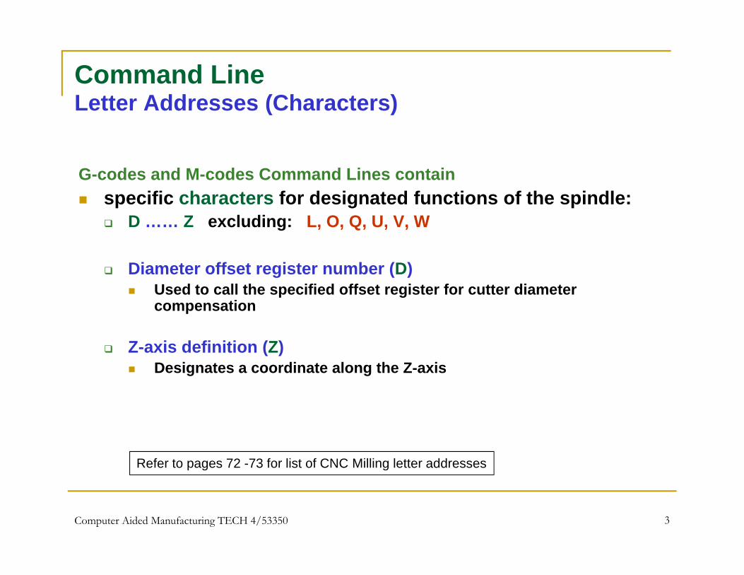
Command LineLetter Addresses (Characters)Letter Addresses (Characters)
G-codes and M-codes Command Lines containG codes and M codes Command Lines contain specific characters for designated functions of the spindle:
D …… Z excluding: L, O, Q, U, V, W
Diameter offset register number (D) Used to call the specified offset register for cutter diameter
compensation
Z-axis definition (Z) Designates a coordinate along the Z-axis
Refer to pages 72 -73 for list of CNC Milling letter addresses
Computer Aided Manufacturing TECH 4/53350 3
p g g

Command LineG-CodesG Codes
G-codes are preparatory functions involve actual toolG codes are preparatory functions involve actual tool moves: Rapid moves, radial feed moves G00 – Position in rapid G00 Position in rapid G01 – Linear Interpolation …………….. Most G-codes remain active until another code is issued
(Modal codes)
Refer to pages 74 for list of CNC Milling G-codes
Computer Aided Manufacturing TECH 4/53350 4

Rapid MoveG00: To Position Spindle in Rapid MovementG00: To Position Spindle in Rapid Movement
Use the G00 command to move the tool linearly and quickly from one point to another without cuttingfrom one point to another without cutting Tool positioning
General Format: N G00 X Y Z N_ G00 X_ Y_ Z_
X , Y and Z represent respective axis along the width, length and thickness of the work piece (the material)
Standard Format for most CNC Machines: Adopt two separate moves Adopt two separate moves
Rapid move in XY plane Rapid Z move Which move should be executed first?
If Z- value represents a cutting move in the negative direction, the X and Y axes should be executed first
If the Z- value represents a move in the positive direction, the X and Y axis should be executed last
Computer Aided Manufacturing TECH 4/53350 5
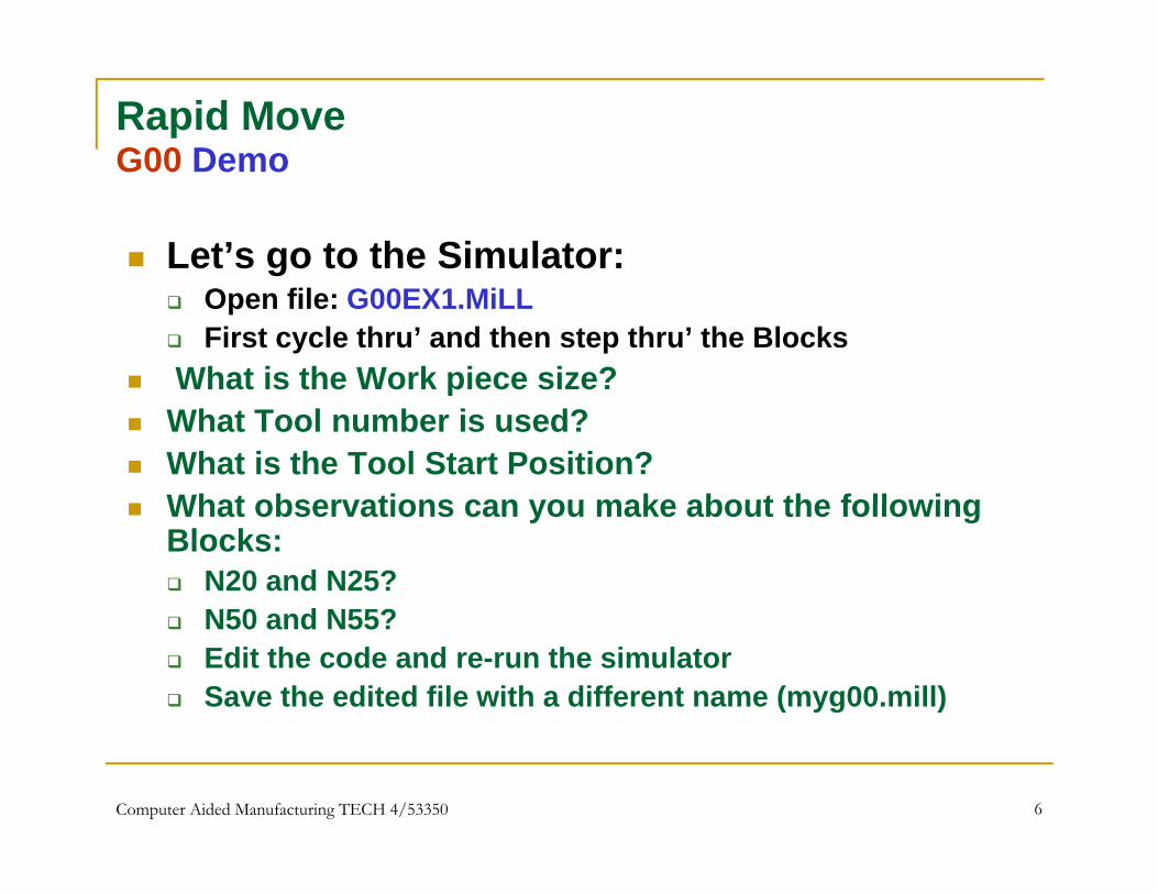
Rapid MoveG00 DemoG00 Demo
Let’s go to the Simulator: Open file: G00EX1.MiLL First cycle thru’ and then step thru’ the Blocks
What is the Work piece size?p What Tool number is used? What is the Tool Start Position? What observations can you make about the following What observations can you make about the following
Blocks: N20 and N25?
N50 and N55? N50 and N55? Edit the code and re-run the simulator Save the edited file with a different name (myg00.mill)
Computer Aided Manufacturing TECH 4/53350 6
Linear InterpolationG01G01
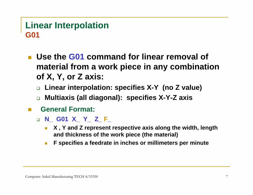
Use the G01 command for linear removal of material from a work piece in any combination of X, Y, or Z axis:
Li i t l ti ifi X Y ( Z l ) Linear interpolation: specifies X-Y (no Z value) Multiaxis (all diagonal): specifies X-Y-Z axis
General Format: General Format: N_ G01 X_ Y_ Z_ F_
X , Y and Z represent respective axis along the width, length and thickness of the work piece (the material)and thickness of the work piece (the material)
F specifies a feedrate in inches or millimeters per minute
Computer Aided Manufacturing TECH 4/53350 7
Linear InterpolationG01 DemoG01 Demo
Let’s go to the Simulator: Open file: G01EX2.MiLL First cycle thru’ and then step thru’ the Blocks
What is the Work piece size?p What Tool number is used? What is the Tool Start Position? What observations can you make about the following What observations can you make about the following
Blocks: N20 and N25?
N30 and N35? N30 and N35? Edit the code and re-run the simulator Save the edited file with a different name (myg01.mill)
Computer Aided Manufacturing TECH 4/53350 8

Circular Interpolation (Clockwise - CW)G02G02
Use the G02 command for all clockwise radial (or arc) feed moves:moves: Quadratic arcs, partial arcs, complete circles Moves must be in a 2-d plane Multiaxis (all diagonal): specifies X-Y-Z axis Multiaxis (all diagonal): specifies X Y Z axis
General Format: N_ G02 X_ Y_ Z_ I_ J_ K_ F_ N_ G02 X_ Y_ Z_ R_ F_
But adopt two separate moves
Let (x0, y0, z0), (x1, y1, z1), (x2, y2, z2) rep the coord of the arc’s center-point, start-point and end-point respectively then: G02 X_ Y_ Z_ I_ J_ K_ F_ = G02 Xx2 Yy2 Zz2 I(x0-x1) J(y0-y1) K(z0 –z1)_ F_ R ifi th di (i th i t l di t f th t ti
or
R specifies the radius (i.e the incremental distance from the starting-point to the center-point)
F specifies a feed-rate in inches or millimeters per minute
Computer Aided Manufacturing TECH 4/53350 9
Circular Interpolation (Clockwise CW)G02 DemoG02 Demo
Let’s go to the Simulator: Open file: G02EX3.MiLL First cycle thru’ and then step thru’ the Blocks
What is the Work piece size?p What Tool number is used? What is the Tool Start Position? What observations can you make about the following What observations can you make about the following
Blocks: N35?
N45 and N50? N45 and N50? Edit the code and re-run the simulator Save the edited file with a different name (myg02.mill)
Computer Aided Manufacturing TECH 4/53350 10
Circular Interpolation (Counter Clockwise - CCW)G03G03
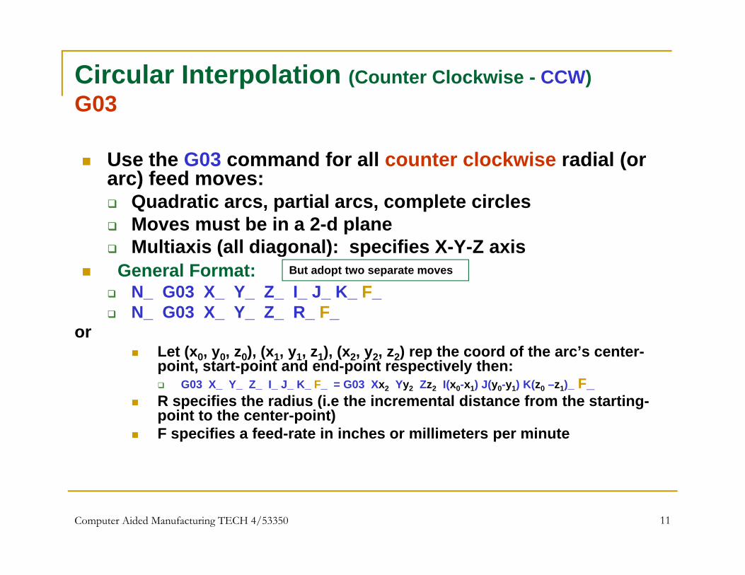
Use the G03 command for all counter clockwise radial (or arc) feed moves:arc) feed moves: Quadratic arcs, partial arcs, complete circles Moves must be in a 2-d plane Multiaxis (all diagonal): specifies X-Y-Z axis Multiaxis (all diagonal): specifies X Y Z axis
General Format: N_ G03 X_ Y_ Z_ I_ J_ K_ F_ N_ G03 X_ Y_ Z_ R_ F_
But adopt two separate moves
Let (x0, y0, z0), (x1, y1, z1), (x2, y2, z2) rep the coord of the arc’s center-point, start-point and end-point respectively then: G03 X_ Y_ Z_ I_ J_ K_ F_ = G03 Xx2 Yy2 Zz2 I(x0-x1) J(y0-y1) K(z0 –z1)_ F_ R ifi th di (i th i t l di t f th t ti
or
R specifies the radius (i.e the incremental distance from the starting-point to the center-point)
F specifies a feed-rate in inches or millimeters per minute
Computer Aided Manufacturing TECH 4/53350 11

Circular Interpolation (Counter Clockwise CW)G03 DemoG03 Demo
Let’s go to the Simulator:g Open file: G03EX4.MiLL First cycle thru’ and then step thru’ the BlocksWhat is the Work piece size? What is the Work piece size?
What Tool number is used? What is the Tool Start Position? What observations can you make about the following
Blocks: N40 N50 and N60? N40, N50 and N60? Edit the code and re-run the simulator Save the edited file with a different name (myg03.mill)
Computer Aided Manufacturing TECH 4/53350 12
Dwell G04G04
Use the G04 command to pause all axis movement for a specified time while spindle continues to revolve at the specified rpm Ideal for clearance of chips after drilling Ideal for clearance of chips after drilling
General Format: N_ G04 P_
The letter P represents time period to pause, and is followed by time measured in seconds (e g for 2 seconds: P2)time measured in seconds (e.g., for 2 seconds: P2)
Computer Aided Manufacturing TECH 4/53350 13

DwellG04 DemoG04 Demo
Let’s go to the Simulator:g Open file: G04EX5.MiLL First cycle thru’ and then step thru’ the BlocksWhat is the Work piece size? What is the Work piece size?
What Tool number is used? What is the Tool Start Position? What observations can you make about the following
Blocks: N30 and N45? N30 and N45? Edit the code and re-run the simulator Save the edited file with a different name (myg04.mill)
Computer Aided Manufacturing TECH 4/53350 14
PlanesXY XZ YZXY, XZ, YZ
The machine tool can move in the horizontal (X-Y) and vertical (Z) directions: Use the G17 command to (re)set system to XY plane
N_ G17 Demo file: G17EX6.MiLL
Use the G18 command to (re)set system to XZ plane N G18 N_ G18 Demo file: G18EX7.MiLL
Use the G19 command to set system in YZ planeN G19 N_ G19
Demo file: G19EX8.MiLL
Computer Aided Manufacturing TECH 4/53350 15
Return to Reference Point (Via Intermediate point)G28G28
Use the G28 command to move tool from a starting point to a predefined reference point via an intermediate positiona predefined reference point via an intermediate position
General Format: N_ G28 N G28 X Y Z (Xk Yn Zm rep radial dist of intermediate point)or _ _ _ _ ( p p )
Demo file: G28EX111.MiLL What observations can you make about block:
N35
Computer Aided Manufacturing TECH 4/53350 16

Return from Reference Point (Via Intermediate point)G29G29
Use the G29 command to move tool from the reference point to the intermediate and finally to the end pointpoint to the intermediate and finally to the end point
General Format: N_ G29 N G29 X Y Z (Xk Yn Zm rep radial dist of intermediate point)or _ _ _ _ ( p p )
Demo file: G29EX112.MiLL What observations can you make about block:
N35
Computer Aided Manufacturing TECH 4/53350 17
More G-codesSimulator RunsSimulator Runs
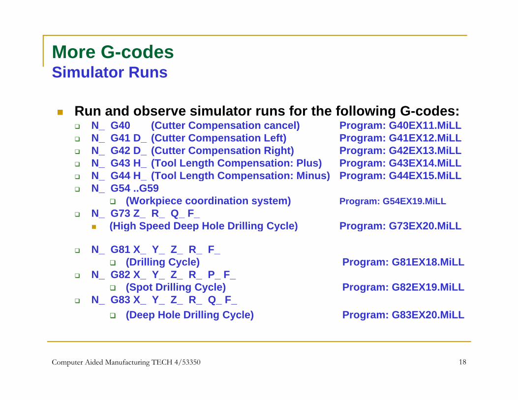
Run and observe simulator runs for the following G-codes: N G40 (Cutter Compensation cancel) Program: G40EX11 MiLL N_ G40 (Cutter Compensation cancel) Program: G40EX11.MiLL N_ G41 D_ (Cutter Compensation Left) Program: G41EX12.MiLL N_ G42 D_ (Cutter Compensation Right) Program: G42EX13.MiLL N_ G43 H_ (Tool Length Compensation: Plus) Program: G43EX14.MiLL N G44 H (Tool Length Compensation: Minus) Program: G44EX15 MiLL N_ G44 H_ (Tool Length Compensation: Minus) Program: G44EX15.MiLL N_ G54 ..G59
(Workpiece coordination system) Program: G54EX19.MiLL N_ G73 Z_ R_ Q_ F_
(High Speed Deep Hole Drilling Cycle) Program: G73EX20 MiLL (High Speed Deep Hole Drilling Cycle) Program: G73EX20.MiLL
N_ G81 X_ Y_ Z_ R_ F_ (Drilling Cycle) Program: G81EX18.MiLL
N G82 X Y Z R P F N_ G82 X_ Y_ Z_ R_ P_ F_ (Spot Drilling Cycle) Program: G82EX19.MiLL
N_ G83 X_ Y_ Z_ R_ Q_ F_ (Deep Hole Drilling Cycle) Program: G83EX20.MiLL
Computer Aided Manufacturing TECH 4/53350 18

Absolute PositioningG90G90
Use the G90 command to set absolute coordinates as the default Coords will be measured from the origin (X0, Y0, Z0)
and expressed in X, Y and Z distancesp , Insert Command at start of program
Format: N_ G90
Simulator Program: G90EX21.MiLL Run Simulator and observe System Status Window Run Simulator and observe System Status Window
Computer Aided Manufacturing TECH 4/53350 19

Incremental PositioningG91G91
Use the G91 command to set incremental coordinates as the default Coords will be measured from previous point and
expressed in X, Y and Z distancesp , Insert Command at start of program
Format: N_ G91
Simulator Program: G91EX22.MiLL Run Simulator and observe System Status Window Run Simulator and observe System Status Window
Computer Aided Manufacturing TECH 4/53350 20

Reposition the Origin PointG92G92
Use the G92 command to reposition the origin point
Format:N G92 X Y Z N_ G92 X_ Y_ Z_
Simulator Program: G92EX23.MiLL Run Simulator and observe System Status Windowy
Computer Aided Manufacturing TECH 4/53350 21