chapter 4: beginning building construction
TRANSCRIPT

Page 58
Chapter 4: Beginning Building Construction
Building Layout
The building layout establishes exact reference lines and elevations. Care in layout makes construction easier and helps keep building square.
REMINDER: Building width and length are from corner column outside to corner column outside! After installing all framing, finished framework will normally be 3” wider and longer than ordered or “call out” dimensions. Ignoring this will result in more effort during construction.
Calculating Diagonal Lengths
Example: building is 50 feet wide and 84 feet long. Explanation: A picture helps greatly with this problem, so we begin with a rectangular post
frame building.
Distance (drawn in red) is diagonal of our rectangle, or k. We should also note this diagonal divides our rectangle into two congruent right triangles. We can therefore find length of our diagonal by focusing on one of these triangles and determining hypotenuse. This can be done with the Pythagorean Theorem, giving us: 50^2 + 84^2 = k^2
2500 +7056 = k^2
9556 = k^2
Taking square root gives us
k=97.754795 feet or 97’ 9-1/16”
Page 59
See Table 4-1 below.
DECIMAL OF A FOOT TO INCH CONVERSION
Feet Inches Feet Inches
0.9167 11 0.0781 15/16
0.8333 10 0.0729 7/8
0.75 9 0.0677 13/16
0.6667 8 0.0625 3/4
0.5833 7 0.0573 11/16
0.5 6 0.0521 5/8
0.4167 5 0.0469 9/16
0.3333 4 0.0417 1/2
0.25 3 0.0365 7/16
0.1667 2 0.0313 3/8
0.0833 1 0.0260 5/16
0.0208 1/4
0.0156 3/16
0.0104 1/8
0.0052 1/16
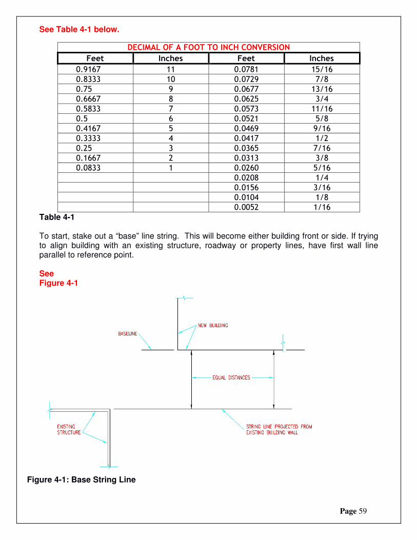
Table 4-1 To start, stake out a “base” line string. This will become either building front or side. If trying to align building with an existing structure, roadway or property lines, have first wall line parallel to reference point. See Figure 4-1
Figure 4-1: Base String Line

Page 60
Locate and set front corner stake “A” along baseline. Drive a nail partially into stake top as a reference point. See Figure 4-2
Figure 4-2: Placing Stakes

Page 61
Hook a tape measure on nail at Stake A. Measure building length along base line from Stake A and set corner Stake B. See Figure 4-3
Use a construction level (transit) and drive Stake B in so Stake A and B tops are level. Drive a nail partially into Stake B top at exact building length (as measured from column outside to column outside).
Figure 4-3: Batter Boards Next make endwall perpendicular to sidewall. Measure 12 feet along base line from Stake A and set a temporary stake. Intersection point 20 feet from this temporary stake and 16’ from Stake A is perpendicular to base line. Set a second temporary stake at this point.

Page 62
See Figure 4-3
Measure outside building width along this line and set Stake D. Drive Stake D into ground…level with Stake A and B tops. Drive a nail partially into Stake D top at exact outside building width. (Figure 4-3) From nail in Stake D top, measure outside building length. From nail in Stake B, measure outside building width. At two measurement intersection, drive last corner Stake C, with top level with previous three corner stake tops. As before, partially drive a nail into Stake C top, at exact outside corner point. (Figure 4-3) Before proceeding, make certain all four corner stakes tops are level. Then double check, in this order – baseline length (A to B), Width B-C and A-D and then length C-D. Adjust nails or stakes B, C, or D as needed. Diagonals AC and BD are to be equal for a rectangular building. Adjust by shifting C and D along rear wall line. Do NOT move A or B. Keep widths B-C and A-D equal. Recheck any shifted stake levels. Drive batter board stakes 8 to 12 feet from all corners. While specific batter board materials are not provided with building kit, girts make excellent batter boards, as long as they remain uncut and undamaged. Batter boards provide a level reference plane for building layout. Place to avoid interfering with excavation, pre-mix deliveries or construction and to remain undisturbed until columns are backfilled. Level and fasten batter boards to stakes at same heights as corner stake tops. Stretch building string lines between batter boards, barely touching nails on corner stake tops. Partially drive nails into batter board tops to line up string lines. Temporary and corner stakes can now be removed. Corners will be located where lines cross.
Photo above shows corner column in hole with batter boards in place.

Page 63
Mark Column Locations
Measuring along building lines, use small temporary stakes or nails painted with fluorescent paint to mark each column location center.
Remember to locate column center, ½ column thickness inside string lines. (Example: 5-1/2” column, column center is 2-3/4” inside string lines.) See Figure 4-4
Figure 4-4: Offset String Lines

Page 64
Figure 4-4 shows column centers as compared to “outside” building line. After column centers have been located, offset (move) building line strings 1-1/2” (splash plank width), from column face outsides. Why offset string lines? While this may sound confusing, failure to offset string lines could result in crooked finished walls, due to columns inadvertently touching lines. We’ve seen professional builders make this error far too often, and in this case, an ounce of prevention, is worth a pound of cure. Once offset, building string lines will now measure 3” greater in dimension than building width and length (column outside to column outside). Measure in from building string line 1-1/2 inches to set each column. Rather than having to use a tape measure each time, a 2x4 or 2x6 scrap block (happens to be 1-1/2” in thickness) can be placed between column and string line.
Digging Holes
Temporarily remove string lines. If building in an area requiring inspections, call building inspector to schedule a hole inspection.
This is important! Get off on right foot with building inspectors. Call for all required inspections!
Confirm hole diameter from building plan. While usually 18-or 24-inch diameter, verify from building plans. Building holes may be made larger in diameter or greater in depth (provided columns are long enough) without adversely affecting building structure. Too small hole diameter, or holes less than depth shown on building plans, could cause a myriad of future structural issues – or even a failure. Why would smaller diameter holes be an issue? Building weight, including a “loaded to failure” roof load, must be adequately distributed to soil beneath concrete under columns. Hole diameters specified on building plans include a sufficient area to resist settling, given stated soil strength. Avoid temptation to use concrete “cookies” placed beneath columns, as they often fail to provide enough surface area to resist settling. To help prevent frost “heave”, dig holes so width at top is less than width at bottom. This can be done by “belling” out hole bottom with a shovel. Using an auger mounted on a skid steer, bore holes to depth required on building plans. Holes slightly larger in diameter than auger bit can be created by first digging a pilot hole then offsetting auger slightly from hole center and boring again. NOTE: High water tables or water in holes will not cause premature pressure preservative treated column decay. Treatment is for structural in ground use, including being exposed to ground water.

Page 65
Helpful hint – an auger will remove rocks up to half auger bit diameter.
In cases where two adjacent columns will be located in close proximity to each other, two holes may resemble a short “trench”. This is acceptable.

Page 66
Holes may be dug larger in diameter than what is shown on building plans, as well as oblong or rectangular. It is acceptable to dig holes with a backhoe or mini-excavator. Dimensions stated on plans are “minimum” requirements. Avoid “over digging” holes! If holes are too deep, extra concrete will be needed and concrete is expensive fill! A visible marker, placed on auger bit at required depth, is often helpful. If large rocks are present, dig holes with a backhoe, mini- excavator or other similar equipment. Extend hole depth below area frost line. If unsure about frost depth, ask local building inspector. After digging, clean any loose materials from hole bottoms.

Page 67
What Happens if Rock Is Encountered? Dig It Out - Even if this leaves a crater numerous feet across, a sonotube can be placed at this column location, properly backfill around and place column in sonotube. This excavation may involve some heavier equipment, like a backhoe. Jackhammer – Unless solid granite has been hit, most rocks can be broken apart by one. Ram Hoe – (also known as a concrete breaker) This is often most practical solution and is an attachment for a skid steer or backhoe. This hydraulic breaker makes quick work out of a tough job. With a smart and efficient design, it provides a workhorse with only two moving parts. Vibration and shock are controlled by shock absorbing polymers, minimizing machine wear and sound while improving operator comfort level. One can easily smash through even concrete. Concrete “cookie” placement or pouring concrete “punch pads” at hole bottoms, beneath columns is unacceptable by the E.O.R.. Neither will be shown on building plans. With column holes properly backfilled with poured concrete, either is usually both structurally inadequate and a needless expense.