chapter 3 – welding 2013 - turkloydu.org · chapter 3 – welding 2013 this latest edition...
TRANSCRIPT

Chapter 3 – Welding
2013 This latest edition incorporates all rule changes. The latest revisions are shown with a vertical line. The section title is framed if the section is revised completely. Changes after the publication of the rule are written in red colour. Unless otherwise specified, these Rules apply to ships for which the date of contract for construction as defined in IACS PR No.29 is on or after 2nd of September 2013. New rules or amendments entering into force after the date of contract for construction are to be applied if required by those rules. See Rule Change Notices on TL website for details. "General Terms and Conditions" of the respective latest edition will be applicable (see Rules for Classification and Surveys). If there is a difference between the rules in English and in Turkish, the rule in English is to be considered as valid. This publication is available in print and electronic pdf version. Once downloaded, this document will become UNCONTROLLED. Please check www.turkloydu.org for the amended and valid version. All rights are reserved by Türk Loydu, and content may not be reproduced, disseminated, published, or transferred in any form or by any means, except with the prior written permission of TL.

TÜRK LOYDU
Head Office Postane Mah. Tersaneler Cad. No:26 Tuzla 34944 İSTANBUL / TÜRKİYE
Tel : (90-216) 581 37 00
Fax : (90-216) 581 38 00
E-mail : [email protected]
http://www.turkloydu.org
Regional Offices
Ankara Eskişehir Yolu Mustafa Kemal Mah. 2159. Sokak No : 6/4 Çankaya - ANKARA / TÜRKİYE
Tel : (90-312) 219 56 34 - 219 68 25
Fax : (90-312) 219 69 72
E-mail : [email protected]
İzmir Atatürk Cad. No :378 K.4 D.402 Kavalalılar Apt. 35220 Alsancak - İZMİR / TÜRKİYE
Tel : (90-232) 464 29 88
Fax : (90-232) 464 87 51
E-mail : [email protected]
Adana Çınarlı Mah. Atatürk Cad. Aziz Naci İş Merkezi No:5 K.1 D.2 Seyhan - ADANA / TÜRKİYE
Tel : (90- 322) 363 30 12
Fax : (90- 322) 363 30 19
E-mail : [email protected]
Marmaris Atatürk Cad. 99 Sok. No:1 Ketenbaş Apt. Kat:4 Daire 6 Marmaris - MUĞLA / TÜRKİYE
Tel : (90- 252) 412 46 55
Fax : (90- 252) 412 46 54
E-mail : [email protected]

Contents
Welding
Section 1- General Rules Page
A. General .................................................................................................................................................... 1-2
B. Other Rules, Standards and Specifications .............................................................................................. 1-2
C. Information in Working Documents ........................................................................................................... 1-3
D. Materials, Weldability ................................................................................................................................ 1-3
E. Welding Consumables and Auxiliary Materials ......................................................................................... 1-4
F. Quality Assurance, Responsibility ............................................................................................................. 1-4
G. Inspection Tests, Liability .......................................................................................................................... 1-5
Section 2- Requirements For Welding Shops, Approval
A. Approval of Welding Shops ...................................................................................................................... 2-2
B. Requirements for Welding Shops ............................................................................................................. 2-3
C. Inspection of Welding Shops..................................................................................................................... 2-4
D. Welding Procedure Tests .......................................................................................................................... 2-5
E. Certification of Approvals, Certificates according to EN 729/ISO 3834 ..................................................... 2-5
Section 3- Welder’s Qualification Tests
A. General .................................................................................................................................................... 3-2
B. Testing Bodies, Certificates ...................................................................................................................... 3-2
C. Scope of Testing and Range of Approval ................................................................................................. 3-3
D. Performance of Welder's Qualification Tests ............................................................................................ 3-4
E. Period of Validity, Repeat Tests ................................................................................................................ 3-4
F. Other Welder's Tests ................................................................................................................................ 3-5
Section 4- Welding Procedure Tests, Production Tests
A. General .................................................................................................................................................... 4-2
B. Performance of Welding Procedure and Production Tests ....................................................................... 4-3
C. Evaluation of Test Results, Requirements, Repeat Test Specimens, Test Reports .................................. 4-6
D. Limits of Application, Period of Validity ..................................................................................................... 4-7
Section 5- Welding Consumables And Auxiliary Materials
A. General .................................................................................................................................................... 5-3
B. Covered Electrodes for Manual Metal-Arc Welding of Hull Structural Steels ............................................ 5-12
C. (Flux-cored) Wire-Gas Combinations and Flux-Cored Wire Electrodes for Semi-Mechanized
Welding of Hull Structural Steels ............................................................................................................... 5-22

Contents
D. Wire-Flux Combinations for Submerged-Arc Welding of Hull Structural Steels ........................................ 5-27
E. Welding Consumables and Auxiliary Materials for Electrogas and Electroslag
Welding of Hull Structural Steels ............................................................................................................... 5-33
F. Welding Consumables and Auxiliary Materials for High-Strength (Quenched and Tempered)
Structural Steels ........................................................................................................................................ 5-35
G. Welding Consumables and Auxiliary Materials for Steels Tough at Subzero Temperatures .................... 5-38
H. Welding Consumables and Auxiliary Materials for High-Temperature Steels ........................................... 5-40
I. Austenitic and Austenitic-Ferritic Welding Consumables And Auxiliary Materials For Stainless
Steels, Non-Magnetic Steels And Nickel Alloy Steels Tough At Subzero Temperatures ......................... 5-43
J. Welding Consumables and Auxiliary Materials for Aluminium Alloys ........................................................ 5-48
K. Welding Consumables and Auxiliary Materials for Copper and Copper Alloys ......................................... 5-52
L. Welding Consumables and Auxiliary Materials for Nickel and Nickel Alloys ............................................. 5-53
Section 6- Overweldable Shop Primers
A. General .................................................................................................................................................... 6-2
B. Approval Testing of Shop Primers ............................................................................................................ 6-2
C. Certification ............................................................................................................................................... 6-3
D. Periodical Control Tests ............................................................................................................................ 6-4
Section 7- General Design Principles
A. General .................................................................................................................................................. 7-2
B. Information Contained in Manufacturing Documents ............................................................................. 7-2
C. Materials, Weldability ............................................................................................................................. 7-3
D. Design Details ........................................................................................................................................ 7-3
E. Dimensioning of Welded Joints .............................................................................................................. 7-5
Section 8- Execution of Welds
A. General .................................................................................................................................................. 8-2
B. Weld Preparation, Assembly .................................................................................................................. 8-3
C. Weather Protection, Preheating ............................................................................................................. 8-3
D. Welding Positions, Welding Sequence ................................................................................................... 8-4
E. Performance of Welding ......................................................................................................................... 8-4
F. Straightening, Tolerances ...................................................................................................................... 8-5
G. Post-Weld-Treatment of Welds .............................................................................................................. 8-5
Section 9- Heat Treatment
A. Scope ..................................................................................................................................................... 9-2
B. Equipment and Appliances for Heat Treatment...................................................................................... 9-2
C. Principles Relating to Heat Treatment .................................................................................................... 9-2
D. Weather Protection, Preheating, Heat Input during Welding .................................................................. 9-3
E. Post-Weld Heat Treatment ..................................................................................................................... 9-8
Contents
Section 10- Non-Destructıve Testing of Welds
A. General .................................................................................................................................................. 10-3
B. Test Methods, Appliances and Test Media ............................................................................................ 10-3
C. Inspection Personnel, Supervisors ......................................................................................................... 10-4
D. Inspection Schedule, Inspection Reports ............................................................................................... 10-4
E. Timing of Inspection, Waiting Times ...................................................................................................... 10-5
F. Preparation and Performance of Tests .................................................................................................. 10-6
G. Evaluation of Test Results ..................................................................................................................... 10-6
H. Extension of the Scope of Inspection ..................................................................................................... 10-8
I. Repairs, Re-inspection ........................................................................................................................... 10-8
J. Visual Inspection .................................................................................................................................... 10-8
K. Radiographic Inspection ......................................................................................................................... 10-9
L. Ultrasonic Inspection ............................................................................................................................ ...10-11
M. Magnetic Particle Inspection .................................................................................................................. 10-16
N. Liquid Penetrant Inspection ................................................................................................................... 10-17
Section 11- Mechanical and Technological Tests
A. Scope ..................................................................................................................................................... 11-2
B. Preparation of Specimens and Testing .................................................................................................. 11-2
C. Tensile Tests .......................................................................................................................................... 11-3
D. Bend Tests ............................................................................................................................................. 11-4
E. Notched Bar Impact Tests ...................................................................................................................... 11-6
F. Hardness Testing of Welds .................................................................................................................... 11-7
G. Metallographic Inspections ..................................................................................................................... 11-8
H. Inspection reports ................................................................................................................................... 11-8
I. Re-Test Procedures ............................................................................................................................... 11-9
Section 12- Welding of Hull Structures
A. General .................................................................................................................................................. 12-3
B. Approval of Shipyards and Welding Shops, Welding Personnel ............................................................ 12-3
C. Quality Inspection, Responsibility ........................................................................................................... 12-4
D. Materials, Weldability ............................................................................................................................. 12-5
E. Welding Consumables and Auxiliary Materials ...................................................................................... 12-5
F. Welding Procedure Qualification Tests of Steels for Hull Construction and
Marine Structures ................................................................................................................................... 12-8
G. Design, Dimensioning ............................................................................................................................ 12-25
H. Execution of Welds ................................................................................................................................ 12-37
I. Inspection of Welded Joints ................................................................................................................... 12-44
Section 13- Welding of Steam Boilers
A. General .................................................................................................................................................. 13-2
B. Approval of Welding Shops, Welding Personnel .................................................................................... 13-2
C. Quality Inspection, Responsibility ........................................................................................................... 13-2
D. Materials, Weldability ............................................................................................................................. 13-3
E. Welding Consumables and Auxiliary Materials ...................................................................................... 13-3

Contents
F. Welding Procedure Tests ....................................................................................................................... 13-4
G. Welding Technique ................................................................................................................................ 13-7
H. Post-Weld Heat Treatment ..................................................................................................................... 13-7
I. Inspection of Welded Components ........................................................................................................ 13-10
Section 14- Welding of Pressure Vessels
A. General .................................................................................................................................................. 14-2
B. Approval of Welding Shops, Welding Personnel .................................................................................... 14-3
C. Quality Inspection, Responsibility ........................................................................................................... 14-3
D. Materials, Weldability ............................................................................................................................. 14-4
E. Welding Consumables and Auxiliary Materials ...................................................................................... 14-4
F. Welding Procedure Tests ....................................................................................................................... 14-5
G. Welding Technique ................................................................................................................................ 14-10
H. Post-Weld Heat Treatment ..................................................................................................................... 14-11
I. Inspection of Welded Components ........................................................................................................ 14-12
Section 15- Welding of Pipelines
A. General .................................................................................................................................................. 15-2
B. Approval of Welding Shops, Welding Personnel .................................................................................... 15-2
C. Quality Inspection, Responsibility ........................................................................................................... 15-3
D. Materials, Weldability ............................................................................................................................. 15-4
E. Welding Consumables and Auxiliary Materials ...................................................................................... 15-4
F. Welding Procedure Tests ....................................................................................................................... 15-7
G. Welding Technique ................................................................................................................................ 15-9
H. Preheating .............................................................................................................................................. 15-10
I. Heat Treatment After Forming and Welding ........................................................................................... 15-10
J. Inspection Of Welded Pipelines ............................................................................................................. 15-12
Section 16- Welding of Machinery Components
A. General .................................................................................................................................................. 16-2
B. Approval of Welding Shops, Welding Personnel .................................................................................... 16-2
C. Quality Inspection, Responsibility ........................................................................................................... 16-3
D. Materials, Weldability ............................................................................................................................. 16-4
E. Welding Consumables and Auxiliary Materials ...................................................................................... 16-4
F. Welding Procedure Tests ....................................................................................................................... 16-4
G. Design, Welding Technique ................................................................................................................... 16-10
H. Post-Weld Heat Treatment ..................................................................................................................... 16-11
I. Inspection of Welded Components ........................................................................................................ 16-11
Annex A Imperfections in Welded Joints in Steel
Annex B Limits on Imperfections
Annex C Comparison of Equivalent, Internationally Recognized Film System Classes
Annex D Welding positions according to AWS-Code

Section 1 – General Rules 1-1
TÜRK LOYDU - WELDING - 2013
SECTION 1
GENERAL RULES
A. GENERAL ........................................................................................................................................................ 1- 2
1. Scope
2. Application in Other Fields
3. Exceptions to these Rules
4. Alterations and Additions
B. OTHER RULES, STANDARDS AND SPECIFICATIONS ................................................................................. 1- 2
1. Other Relevant Standards
2. Differences in Requirements
C. INFORMATION IN WORKING DOCUMENTS ................................................................................................... 1- 3
1. Drawings, Other Working Documents
2. Additional Information and Documentation
D. MATERIALS, WELDABILITY ............................................................................................................................ 1- 3
1. Choice of Material
2. Proof of Weldability
3. Supervision during Fabrication
E. WELDING CONSUMABLES AND AUXILIARY MATERIALS .......................................................................... 1- 4
1. Test of Product Suitability, Approval
2. Supervision during Fabrication
F. QUALITY ASSURANCE, RESPONSIBILITY ................................................................................................... 1- 4
1. Compliance with Rules, Quality Inspections
2. Placing Subcontracts
3. Deviation from Approved Working Documents, Repairs
4. Marking and Identification of Materials
5. Marking of Welds
G. INSPECTION TESTS, LIABILITY ...................................................................................................................... 1- 5
1. Presentation of Components
2. Supplying of Test Documentation
3. Subsequent Defects

1-2 Section 1 – General Rules A,B
TÜRK LOYDU - WELDING - 2013
A. General
1. Scope
1.1 These Rules apply to all welding work
performed in the course of new construction, conversion
or repairs carried out on ships and their machinery
installations, including steam boilers, pressure vessels
and pipelines, for which an application for classification
has been submitted to Türk Loydu (TL) or which have
been classified by TL.
Note:
The terms "welding", "welding work", "welding process" etc.
used in these rules also cover all other thermal and/or
mechanized joining processes such as brazing which, because
they are deemed as "special processes" under the terms of the
quality assurance standards, require pre-qualification which
has to be carried out by qualified personnel and constantly
monitored.
1.2 They also apply to all welding work on
components, installations or implements for which the
Society has issued rules, regulations or other technical
directions in which reference is made to these Welding
Rules.
1.3 These Welding Rules shall be applied in
analogous manner where other rules, regulations or
technical directions issued by TL contain no special
instructions with regard to welding work.
2. Application in Other Fields
These Welding Rules may be applied in analogous
manner to welding work carried out on structures and
components other than those mentioned under 1., the
supervision and inspection of which is the concern of
TL. Where necessary, appropriate arrangements shall
be made with TL.
3. Exceptions to these Rules
Exceptions to these Welding Rules require the consent
of TL in each individual case.
4. Alterations and Additions
TL reserves the right to alter or add to these Rules
from time to time, should this prove necessary on the
basis of more recent knowledge or operating
experience.
B. Other Rules, Standards and Specifications
1. Other Relevant Standards
1.1 The standards or other technical directions
mentioned in the following sections form an integral part
of these Welding Rules and shall also be complied with.
The same applies to the working documents, e.g.
drawings, welding specifications, etc. approved by TL.
1.2 Where the following sections refer to standards
in which a date is specified, the current version shall
apply.
1.3 Where the following sections and chapters
refer to both EN and ISO standards, and if, where they
are both specified, the standards are not identical, the
EN standards shall take precedence. Where the two
standards are identical, either the EN or the ISO
standard may be used.
1.4 The application of other rules, standards,
regulations or other technical directions is subject to the
consent of TL in each individual case. TL may make
any such approval conditional upon construction and
dimensioning also being subject to these directions.
2. Differences in Requirements
If there are differences in requirements between these
Rules and other relevant standards or specifications,
the requirements of these Welding Rules shall take
precedence, unless otherwise stipulated.

C,D Section 1 – General Rules 1-3
TÜRK LOYDU - WELDING - 2013
C. Information in Working Documents
1. Drawings, Other Working Documents
1.1 The drawings and other working documents
to be submitted before commencing the fabrication
work must contain all the necessary details for the
preparation, execution and, where applicable, the
inspection of the welds.
This information shall in particular include details of:
- Base materials, shapes and dimensions of
products,
- Welding processes, welding consumables and
auxiliary materials,
- Shapes and dimensions of welds,
- Preheating and heat input during welding,
- Heat treatment after welding,
- Subsequent treatment of the welds,
- Nature and scope of inspections,
- Requirements applicable to the welded joints
(e.g. quality grade, weld performance,
evaluation category or the like).
1.2 Provided that in the fabrication of ship's
structures, the materials, welding processes, welding
consumables, auxiliary materials and the shapes and
dimensions of welds conform to normal shipbuilding
practice, these Rules and the approvals, these details
need not be specified.
2. Additional Information and Documentation
For particular structures (e.g. liquefied gas tanks),
materials (e.g. quenched and tempered structural steels
and clad plates) or welding processes, the following
additional information and documentation shall be
provided as necessary:
- Weld preparation, assembly, auxiliary (tack)
welds,
- Welding positions, welding sequence
(drawings)
- Weld build-up, number of passes,
- Heat input during welding (heat input per unit
length of weld).
This information shall be combined in a welding
specification. For test schedules and specifications for
non-destructive testing, please refer to Section 10.
D. Materials, Weldability
1. Choice of Material
All materials shall be of proven weldability. They shall
be chosen in accordance with the intended application
and the conditions of service and shall comply with the
requirements stated in Material Rules. Their properties
shall be documented to the specified extent by test
certificates, e.g. in conformity with EN 10204.
Note:
The hull structural steels and rolled products described in
Material Rules, for the manufacture of steam boilers,
pressure vessel, pipelines and machinery are deemed to be of
proven weldability.
2. Proof of Weldability
If, not withstanding item. 1., materials are to be welded
whose properties are not described in TL Material
Rules, the welding shop concerned shall furnish proof of
their weldability (e.g. by reference to existing standards)
or submit special material specifications for approval. If
there is doubt as to the weldability of a material, the
welding shop shall specially demonstrate this in the
course of the welding procedure tests.

1-4 Section 1 – General Rules D,E,F
TÜRK LOYDU - WELDING - 2013
3. Supervision during Fabrication
The welding shop shall ensure that only materials which
meet the requirements of 1. and 2. are used for both
original and replacement supplies, and shall furnish
proof thereof to the Surveyor on request.
E. Welding Consumables and Auxiliary
Materials
1. Test of Product Suitability, Approval
1.1 The welding consumables and auxiliary
materials shall enable a welded joint to be made which
is suited to the base material and the operating condi-
tions. They shall have been tested for product suitability
in accordance with Section 5 and approved for the
application in question. This provision applies in an
analogous manner to brazing metals.
1.2 Approval shall as a rule have been given by
TL. If, in special cases, e.g. repairs, no welding
consumables which have been tested by TL are
available, welding consumables approved by other
recognized testing bodies may be used with TL's
consent. Relevant proof of this must be submitted to
TL's surveyor.
2. Supervision during Fabrication
The welding shop's supervisors shall ensure that only
tested welding consumables and auxiliary materials
which have been approved by TL are used and shall
furnish proof thereof to the Surveyor on request
F. Quality Assurance, Responsibility
1. Compliance with Rules, Quality Inspections
1.1 Shipyards or welding shops are responsible for
ensuring that the welding work conforms to these and
any supplementary rules as applicable, the approved
working documents, any conditions as may be stated in
the approvals, good shipbuilding practice, and also the
state of the art technology relating to welding.
1.2 Shipyards or welding shops must ensure, by
means of regular in-house quality inspections during the
production process and at the end of the welding work,
that such work has been properly and expertly
executed. The responsibilities of the welding supervi-
sors are also covered in ISO 14731. The tests to be
performed by TL surveyors shall not relieve the welding
shop of this responsibility.
1.3 The range and extent of the quality inspections
required is determined by the structure in question. In
each case, however, it is necessary to ensure that the
specified materials, welding consumables and auxiliary
materials are used and that weld preparation, assembly,
performance of tack and welding work, together with the
accuracy to size and completeness of the components
and welded joints meet the requirements.
1.4 Following inspection by the welding shop and
any repairs which may be necessary, the components
must be presented to TL's Surveyor for inspection at
appropriate stages of construction, easily accessible
and as a rule unpainted. The Surveyor may reject those
components which have been inadequately inspected
by the welding shop and specify that a component be
presented again after a successful inspection by the
welding shop and, where necessary repairs.
2. Placing Subcontracts
2.1 When placing orders with subcontractors,
independent branch companies or suppliers as well as
outside companies working in the welding shop who are
themselves approved (so-called "contract companies",
see note Section 2, A.1.1) the "prime contractor" must
ensure that the provisions stated in 1. are also complied
with by the "subcontractors".
2.2 Where the outside companies working in the
welding shop are not themselves approved or where
contract labour is used, the welding shop placing the
contract shall be responsible for ensuring that the
conditions stated in 1. are complied with and that the
quality inspections are performed. TL shall be notified of
the placing of subcontracts or the use of contract labor.

F,G Section 1 – General Rules 1-5
TÜRK LOYDU - WELDING - 2013
3. Deviation from Approved Working Docu-
ments, Repairs
3.1 If alterations to the design compared with the
approved drawings or deviations from approved
fabrication procedures become necessary, the welding
shop shall promptly obtain TL's consent thereto. TL's
Surveyor shall be notified of any repairs which become
necessary during fabrication.
3.2 If, due to inadequate or incorrect information
in the production documents (e.g. workshop drawings),
the quality or functional capability of a component
cannot be guaranteed or is doubtful, TL may require
appropriate repairs to be carried out.
3.3 This shall apply in an analogous manner to
supplementary or additional components (e.g. rein-
forcements) even if these are not specified during the
examination of the drawing or could not be specified
owing to a lack of detail shown in the "class plans" (see
Chapter 1 - Hull, Section 1, G.).
4. Marking and Identification of Materials
4.1 The materials shall be marked in such a way
that they can be identified and matched up with the test
certificates even during and after fabrication.
4.2 If the marking is likely to be erased during
manufacture, the welding shop shall promptly see to it
that it is transferred to another part of the product. This
can be dispensed with in the case of small parts of
minor importance such as ribs or bracings, provided
that any confusion of materials can be prevented by
operational means.
5. Marking of Welds
5.1 In the fabrication of steam boilers and vessels
under internal pressure, each weld section shall be
marked with the symbol of the welder who executed it.
This may be dispensed with if the welding shop
supervisory staff keeps a record of the names of the
welders who execute the individual weld sections.
5.2 In special cases, TL may also require
marking or record-keeping as described in 5.1 for other
components or their welded joints.
G. Inspection Tests, Liability
1. Presentation of Components
The welding shop shall be obliged to present the
components to the Surveyor for the required
intermediate and final inspections. Steps shall be taken
to ensure unimpeded access to the welds. The welds
shall not be treated with coatings or preservatives which
make it difficult or impossible to assess the condition of
the welds.
2. Supplying of Test Documentation
For the inspections, all the manufacturer's records and
documents concerning the quality assurance measures
undertaken by him shall be submitted. These include in
particular:
- Drawings (approved if required) and other
working documents,
- Material test certificates,
- Welder's and welding procedure test
certificates,
- Test reports and films of the non-destructive
tests,
- Certificates of hot-forming and heat treatment,
where applicable,
- Results of production tests, intermediate
results if necessary.
3. Subsequent Defects
3.1 TL gives no guarantee that the products,
welded structures or components tested by its Surveyor
to the extent laid down (normally random tests) conform
to the requirements in every respect and that their
manufacture has been performed correctly and in
accordance with the tested procedures.
3.2 Products or welded structures which prove
defective in subsequent use or in the operation or
processes which exhibit deficiencies in use may be
rejected even if an earlier inspection was satisfactory, if
it is not possible to remedy the defect or deficiency.

Section 2 – Requirement for Welding Shops, Approval 2-1
TÜRK LOYDU - WELDING - 2013
SECTION 2 REQUIREMENTS FOR WELDING SHOPS, APPROVAL
A. APPROVAL OF WELDING SHOPS ................................................................................................................ 2- 2
1. General
2. Application for Approval
3. Approval Documents
4. Period of Validity of Approval, Renewal
5. Changes, Revocation
B. REQUIREMENTS FOR WELDING SHOPS ...................................................................................................... 2- 3
1. Technical Equipment
2. Welding Shop Supervisory Staff
3. Welders and Operators
4. Test Supervisory Staff and Test Personnel
C. INSPECTION OF WELDING SHOPS ............................................................................................................... 2- 4
1. Shop Inspection
2. Submission of Documentation
D. WELDING PROCEDURE TESTS ..................................................................................................................... 2- 5
1. General Provisions
2. Scope of the Welding Procedure Test
3. Recognition of Other Tests
E. CERTIFICATION OF APPROVALS, CERTIFICATES ACCORDING TO EN 729/ISO 3834 ............................ 2- 5

2-2 Section 2 – Requirement for Welding Shops, Approval A
TÜRK LOYDU - WELDING - 2013
A. Approval of Welding Shops
1. General
1.1 Shipyards and welding shops, including
branches and subcontractors, wishing to perform
welding work covered by these Rules must have been
approved for this work by TL. (See Section 12, 13, 14,
15, 16). The preconditions for this approval are that the
shops satisfy the requirements under B., have been
inspected by TL in accordance with C. and, where
necessary, have carried out welding procedure tests in
accordance with D.
Note:
The term "welding shop" used in the following paragraphs is
understood to mean the welding production plant which, due
to its space and organizational facilities, can be regarded as
an independent unit. Branches and subcontractors shall
generally be regarded as "independent" facilities which have
to meet the requirements stated below. In particular, each
welding shop must have available its own permanent in-house
welding supervisory staff. Outside companies working in
welding shops may be approved as independent companies.
For details of this and contract labour, see Section 1, F.2.
1.2 Any approval in accordance with 1.1 covers
the most essential welding quality requirements in
accordance with the standards ISO 3834. For
certification under the terms of these standards, the
requirements set out in 2.2 and 3.2 must also be met.
These additional requirements shall be regarded as
having been met when the welding shop has in place a
certified quality assurance system in accordance with
the series of standards ISO 9000.
1.3 In individual valid exceptions, e.g. in the case
of repairs, TL may grant approval for welding work to be
executed even without approval being granted to the
welding shop, subject to a time limit and restricted to a
specific structure, if the welding shop pre-conditions
have been specified for such work and the quality of the
welds performed is demonstrated by relevant tests, e.g.
non-destructive and/or production tests.
2. Application for Approval
Introductory remark:
Where no special provisions are given in the following
paragraphs or, in an individual case, no other arrangements
are made, the provisions for "Approval" set out in
accordance with these rules shall also apply in an analogous
manner to "Certification" in accordance with ISO 3834.
2.1 Approval shall be applied for in writing to the
TL's head office. The application shall contain the
following details, which shall be related to each other as
far as possible, of the scope of the desired approval:
- Nature of the structure and/or components,
- Materials and dimensional ranges,
- Welding procedures and positions,
- Heat treatments (if necessary)
- Weld factor (for steam boilers and pressure
vessels).
2.2 If a certificate of compliance with the welding
quality requirements stipulated in ISO 3834-2, -3 or -4 is
required over and above approval in accordance with
these Rules for Welding, this must be expressly noted
in the application for approval.
3. Approval Documents
3.1 Welding shops applying for approval to carry
out welding work must submit the following documents
to the TL’s head office with their application for
approval:
- A description of the welding shop
- Copies of the qualification documents of the
welding supervisor(s)
- Copies of the valid welder's certificates or a list
of the qualified welders (testing standard,

A,B Section 2 – Requirement for Welding Shops, Approval 2-3
TÜRK LOYDU - WELDING - 2013
testing body, date of testing, test category,
date of last retest) signed by the Surveyor.
- Copies of documentation as proof of the
qualification of supervisory and test personnel,
as appropriate.
- Copies of reports of welding procedure tests
performed elsewhere, including the approvals
granted, as appropriate
3.2 For certification in accordance with 2.2,
information and documents relating to the elements
specified in Annex 1 to ISO 3834-1 for the respective
grade of requirement (ISO 3834-2 = full, -3 = standard,
or -4 = basic quality requirements) must also be
enclosed with the application for approval (e.g. in the
form of relevant procedure instructions):
- Contract review,
- Design review,
- Treatment of subcontractors ,
- Equipment maintenance,
- Quality inspections,
- Nonconformance,
- Calibration,
- Identification,
- Traceability.
If the welding shop operates a certified quality
assurance system conforming to the series of standards
ISO 9000, the QA manual and - if specified in Annex 1
to ISO 3834-1 - documentation relating to the quality
assurance measures performed (quality reports) must
be submitted to TL for inspection in place of the above
information and documents.
4. Period of Validity of Approval, Renewal
4.1 An approval granted according to these Rules
or certification in accordance with ISO 3834 shall be
valid for three years. Provided that welding work is
constantly performed under TL's supervision during the
validity of the approval and that the preconditions on
which approval was granted have not changed,
approval may be extended on application by the
welding shop for further three years subject to an
appropriate inspection.
4.2 If no welding work has been carried out under
TL's supervision for more than a year, an application for
renewal of the approval, enclosing updated information
as specified in 3., must be made no later than the end
of the 3-year period of validity. Approval may only be
renewed if the necessary preconditions continue to
apply, which shall be verified by a re-inspection of the
welding shop. The approval may then be renewed for a
further period of three years.
5. Changes, Revocation
5.1 If the preconditions under which approval was
granted change, e.g. through the use of untested
welding procedures, materials and/or welding
consumables, or if changes are made to the welding
shop supervisory staff, TL shall be notified voluntarily.
As a rule, this necessitates a revision of the approval.
5.2 An approval shall cease to be valid if the
preconditions under which it was granted cease to
apply. If serious defects are detected in the components
or the welds, TL is entitled to carry out interim
re-inspections of the production facilities and may, if
necessary, revoke the approval.
B. Requirements for Welding Shops
1. Technical Equipment
1.1 Welding shops must have at their disposal
suitable workshops, equipment, machinery and jigs on a
scale necessary for proper performance of the welding
work. This includes, for example, the provision of
storage facilities and baking equipment for the welding
consumables and auxiliary materials, preheating and
heat treatment equipment, testing appliances and
equipment, and means of weather protection for
carrying out welding work in the open air.

2-4 Section 2 – Requirement for Welding Shops, Approval B,C
TÜRK LOYDU - WELDING - 2013
1.2 Equipment and facilities not belonging to the
welding shop itself, e.g. testing appliances, may be
taken into account when evaluating the capabilities of a
welding shop, provided that the preconditions
necessary to proper fabrication and testing are satisfied
and that such equipment is available without restriction.
2. Welding Shop Supervisory Staff
2.1 Welding shops or branches (see note to A.1.)
shall have at least one fully qualified welding supervisor,
who is responsible for ensuring that the welding work is
competently performed. Welding supervisors shall have
training and experience corresponding to the scope of
the fabrication work and shall provide TL with the
necessary documentary proof thereof.
2.2 The names of the welding supervisor in
charge and his deputy must be notified to TL. If the
supervision role is carried out by more than one person,
the responsibilities and tasks of each person must be
established and specified. The welding supervisor in
charge and his deputy shall be recognized by TL as
part of the approval for the welding shop.
2.3 The following persons shall be appointed as
welding supervisors depending on the nature and scope
of the work:
- Welding engineers for fabrication of important
components of the hull structure and of off-
shore installations, also of handling equipment,
steam boilers, pressure vessels, pressure lines
and engine and transmission components,
- Welding specialists for fabrication of simpler or
less heavily stressed components.
For information relating to the qualification of the
welding supervisory staff, their tasks and
responsibilities, see ISO 14731.
2.4 The welding supervisor(s) shall be perma-
nently employed by the welding shop. Supervision of
the welding work by outside staff is not acceptable.
3. Welders and Operators
3.1 Welding shops shall be staffed with qualified
welders and, for fully mechanized and automatic
welding equipment, adequately trained operators. The
required number of qualified welders is determined by
the size of the welding shop and the scope of the
welding work to be performed under TL supervision.
However, a minimum of two qualified welders are
required for each welding process.
3.2 Welders for manual and semi-mechanized
welding must have passed a test in accordance with
Section 3 and in conformity with a recognized standard
(e.g. EN ISO 9606-2, EN 287/ISO 9606, ASME Section
IX or TSE as applicable). The test shall cover the
conditions likely to occur in the fabrication work with
regard to the process(es), base material, welding con-
sumable and welding position(s). The production of test
pieces in a successfully completed welding procedure
or production test may be taken as proof of manual skill
for testing of welders.
3.3 Operators of fully mechanized or automatic
welding equipment and of welding robots must have
been trained in the use of the equipment. They must
also be capable of setting or programming and
operating the equipment in such a way that the required
weld quality is achieved. The qualification of such
personnel must be demonstrated in accordance with EN
1418/ISO 14732 on welded test pieces, e.g. in welding
procedure or fabrication tests or by means of random
tests and operational tests as applicable (please refer to
the standards).
4. Test Supervisory Staff and Test Personnel
Where the welding shop has its own test supervisory
staff and test personnel (see Section 10, C.),
documentary proof of their qualification (e.g. certificates
conforming to ISO 9712) shall be submitted to TL.
C. Inspection of Welding Shops
1. Shop Inspection
Before starting fabrication work, it shall be proved to
TL's Surveyor in the course of an inspection of the
welding shop that the requirements applicable to the
technical equipment as stated in B.1. are satisfied. For
this purpose the Surveyor shall be given access to all

C,D,E Section 2 – Requirement for Welding Shops, Approval 2-5
TÜRK LOYDU - WELDING - 2013
departments and laboratories relevant to fabrication and
testing. The fabrication and quality control procedures
shall also be described and explained to him if he so
requests. For certification according to ISO 3834,
compliance with the additional quality requirements
stated in the standards shall be demonstrated to the
Surveyor (see A.3.2).
2. Submission of Documentation
As part of the welding shop inspection procedure,
originals of all documents necessary in order to evalu-
ate the fabrication and quality assurance procedures
shall be submitted to the Surveyor. These especially
include the welding supervisor's qualification docu-
ments, welder's certificates, reports on previous welding
procedure tests, and results of quality tests and welder's
retests. For certification according to ISO 3834,
compliance with the additional quality requirements
stated in the standards shall be demonstrated to the
Surveyor (see A.3.2).
D. Welding Procedure Tests
1. General Provisions
1.1 If welding procedure tests are required, their
successful performance shall be a further precondition
for the approval of a welding shop or for extending its
approval. Requirements for the performance of these
tests and requirements applicable to test results are
given in Section 4, 12 and 16.
1.2 Welding procedure tests shall be performed in
such a way that the conditions of fabrication can be
covered with regard to materials, welding processes,
welding positions, welding consumables and auxiliary
materials, wall thicknesses, shapes of welds and heat
treatments. The properties of the base materials for the
test pieces shall be documented by test certificates.
2. Scope of the Welding Procedure Test
Note:
Please refer to the detailed information given in Section 4, D.
2.1 In general, a welding procedure test is valid
only within the limits specified in the approval and is not
transferable from the welding shop where it is performed
to a different welding shop. TL may permit exceptions in
the case of a nearby branch welding shop which is under
the constant supervision of the main welding shop, where
the same fabrication conditions prevail and where the
same welding processes are used.
2.2 Welding procedure tests performed in a
workshop are in general not simultaneously valid for
welding in the field. In such cases, the welding
procedure test must be repeated in whole or in part
under field conditions as determined by TL. TL may
waive the repeat testing by prior agreement if the
properties of the field welds are documented by
production tests.
3. Recognition of Other Tests
Welding procedure tests performed under the supervision
of other testing bodies which are independent of the
works may be recognized in full or in part by TL at the
welding shop's request if this is acceptable on the basis
of the test results. In such a case, the complete test
reports and the approval certificate of the other testing
body shall be submitted to TL for evaluation.
E. Certification of Approvals, Certificates
According to ISO 3834
1. TL issues certificates for the approval of
welding shops to carry out welding work and for welding
procedure tests if the requirements set out in these
rules are satisfied in the tests. These welding shop and
welding procedure approvals are valid within the limits
stated in the certificates.
2. Where proof has been furnished that the
additional requirements listed in A.3.2 according to ISO
3834 have been met, TL issues a certificate based on
this in accordance with this standard.
3. If previously issued approval certificates are
replaced or supplemented by more recent ones (see
A.5.1) and the details in the more recent approval
certificates contradict those of previous approvals, the
details in the more recent certificate shall be valid. This
applies especially to the range of application, e.g. for a
specific welding process.

Section 3 – Welder’s Qualification Tests 3-1
TÜRK LOYDU - WELDING - 2013
SECTION 3 WELDER’S QUALIFICATION TESTS
A. GENERAL ......................................................................................................................................................... 3- 2
1. Required Testing (Welding Processes)
2. Training, Manual Skill, Knowledge
3. Lists of Welders, Symbols
B. TESTING BODIES, CERTIFICATES ................................................................................................................. 3- 2
1. Initial Tests in the Welding Shop
2. Repeat Tests in the Welding Shop
3. Tests Conducted by Other Testing Bodies
4. Tests Conducted as Part of the Welding Procedure Tests
C. SCOPE OF TESTING AND RANGE OF APPROVAL ....................................................................................... 3- 3
1. Base Materials
2. Joint Types
3. Other Inclusions and Exclusions
4. Deviations, Special Features, Particular Applications
D. PERFORMANCE OF WELDER'S QUALIFICATION TESTS ............................................................................ 3- 4
1. Welding of Test Pieces, Welding Procedure Specification (WPS)
2. Test Pieces, Specimen Types and Tests
3. Evaluation of Test Pieces and Specimens, Recording of Results
E. PERIOD OF VALIDITY, REPEAT TESTS.......................................................................................................... 3- 4
1. Standard Period of Validity
2. Reduced Period of Validity
3. Continuous Supervision
4. Extensions to the Period of Validity, Repeat Tests
F. OTHER WELDER'S TESTS ............................................................................................................................... 3- 5
1. Other Rules and Standards
2. Exceptions

3-2 Section 3 – Welder’s Qualification Tests A,B
TÜRK LOYDU - WELDING - 2013
Preliminary remarks:
The following rules for the testing of welders conform to or
make use of the standards EN 287 resp. ISO 9606, Parts 1
(Steel) and 2 (Aluminium). For other non-ferrous metals, EN
ISO 9606-2 shall continue to apply until the corresponding
parts of EN 287 and ISO 9606 come into force.
Where no details of the tests are specified in the following
Rules, the tests shall be performed in accordance with these
standards. References in the text also refer to these standards
unless otherwise specified.
Some deviations from the standards have been made with
regard to the testing of steel welders (EN 287-1 resp. ISO
9606-1), especially in relation to the ranges of approval for
base materials and weld types which have been somewhat
narrowed down compared with the standards. As far as the
testing of non-ferrous metal welders is concerned, it is chiefly
the weld forms which differ from those of the standard.
A. General
1. Required Testing (Welding Processes)
1.1 Welder's qualification tests are required for all
welders who are to perform welding work using manually
guided welding appliances (as for manual metal arc
welding or semi-mechanized gas-shielded metal arc
and/or welding using flux-cored electrodes) and where
the quality of the welded joints depends mainly on the
manual skill of the welder.
1.2 For welders who are required to perform
welding work on steam boiler installations, the Technical
Rules for Steam Boilers, TRD 201, Annex 2, Guidelines
for testing and supervising boiler welders, shall also be
complied with. The inclusions and exclusions specified in
these Regulations shall apply hereto.
1.3 The qualification of operators of fully mecha-
nized and automatic welding equipment and of welding
robot, shall be demonstrated in accordance with EN
1418/ISO 14732 on welded test pieces e.g. as part of the
welding procedure or fabrication tests or by means of
random tests and operational tests (see the standards).
2. Training, Manual Skill, Knowledge
2.1 Welder's qualification tests may only be taken by
welders who have received appropriate previous training
(both practical and theoretical) and who have had
sufficient opportunity to practise the craft.
2.2 Besides the necessary manual skill, the welder
shall also possess the professional knowledge enabling
him to perform the welding work competently and safely.
See the relevant information in the standards.
3. Lists of Welders, Symbols
3.1 Welding shops are required to maintain lists or
files which furnish information about the number, names
(code number) and test scope of the welders and the
dates of their initial and repeat tests. These lists shall be
submitted to TL for examination on demand together with
the relevant original documentation or, where
appropriate, together with the description of the welding
shop. (See Section 2, A.3).
3.2 Each welder shall be assigned an
unmistakeable symbol, which shall be recorded in the
testing documentation (certificates, lists, etc.). TL may in
addition - depending on the application - require the
components and welds to be marked with the symbol of
the welder who performed the work. (See Section 1, F.5).
B. Testing Bodies, Certificates
1. Initial Tests in the Welding Shop
The initial testing of welders in the welding shop is to be
conducted by the welding supervisory staff in the
presence of TL's representative. Following submission of
the assessment forms completed by the welding shop
and initialled by the Surveyor, these tests will be
confirmed by TL Head Office in the form of test
certificates.
2. Repeat Tests in the Welding Shop
2.1 Repeat tests taken by welders who have been
certified by TL or by those certified by other recognized
testing bodies and recognized by TL may be conducted

B,C Section 3 – Welder’s Qualification Tests 3-3
TÜRK LOYDU - WELDING - 2013
independently by the welding engineer recognized by TL
in conjunction with the approval granted to the welding
shop. Tests conducted by other welding supervisors shall
be carried out in the presence of TL's representative.
2.2 The extension of the validity of a test certified
by TL by a further two years may, however, only be
authorized by TL. For this purpose, a full set of test
documentation (welding procedure specification,
assessment form and test certificate) must be submitted
to the Surveyor. See E.4.
3. Tests Conducted by Other Testing Bodies
Welder's qualification tests conducted by other testing
bodies (e.g. welding training and testing establishments
or welding training establishments, see the foreword to
DIN EN 287 and EN ISO 9606) which are independent of
the welding shop and which are recognized by TL will be
recognized by TL subject to the test categories specified
below. Such recognition is subject to the submission to
TL of a full set of test documentation, as described in 2.2
above.
4. Tests Conducted as Part of the Welding
Procedure Tests
The testing of welders may be included in the welding
procedure tests see Section 4, B.5.3 and their names will
then be included in the welding procedure approval. A
welder's qualification test certificate conforming to the
standards may, however, only be issued provided that all
the provisions of the standards, e.g. scope of test and job
knowledge testing, have been met and that this is
recorded in an assessment form which has been
completed accordingly.
C. Scope of Testing and Range of Approval
1. Base Materials
1.1 In the case of base materials - and in contrast to
the provisions of the standards EN 287-1 resp. ISO 9606-
1 - higher-strength (hull structural) steels with a minimum
yield strength ReH of up to 355 [N/mm2] (up to 360
[N/mm2] in the case of pipe-grade steels) shall only be
considered, following testing, as being included in the
material category W 01 if the test (using the appropriate
welding consumables) was also performed on a higher-
strength steel.
1.2 Unless otherwise stipulated by TL in a particular
case, the test categories conforming to the standards
shall also apply to the base materials. TL may, however,
require a more precise subdivision of the categories in
accordance with the note to Section 12, F.2.
2. Joint Types
2.1 In the case of joint types - and in contrast to the
provisions of the standards - the test performed on butt
welds does not also include fillet welds. Where welders
are required to lay down butt welds as well as fillet welds,
both weld forms must be included in the test.
2.2 Unless otherwise stipulated by TL in a
particular case, the test categories conforming to the
standards shall also apply to the weld forms.
3. Other Inclusions and Exclusions
Unless otherwise specified by TL in a particular case, the
inclusions and exclusions stipulated in the standards
shall otherwise apply.
4. Deviations, Special Features, Particular
Applications
4.1 If deviations from the standards or these rules
for testing are to be included in the welder's qualification
test, this shall be agreed with TL beforehand. The kind of
the deviation or special feature is to be indicated on the
assessment form under "Remarks" and will be noted in
the test certificate.
4.2 Welder's qualification tests for particular
applications (particular materials, shapes of weld, welding
processes) which are not covered by the tests and work
assignments described above and in the standards (e.g.
for clad plates or offshore pipe junctions) shall be carried
out according to a test schedule to be agreed with TL on
a case-by-case basis.

3-4 Section 3 – Welder’s Qualification Tests D,E
TÜRK LOYDU - WELDING - 2013
D. Performance of Welder's Qualification Tests
1. Welding of Test Pieces, Welding Procedure
Specification (WPS)
For welding test pieces, a "Manufacturer's" Welding
Procedure Specification (WPS) shall be produced by the
welding shop - a separate one for each welding task - in
accordance with the standards EN 287 resp. ISO 9606.
The welding conditions for testing shall match those
during fabrication.
2. Test Pieces, Specimen Types and Tests
The test pieces, the specimen types and the performance
of the tests shall conform to the standards.
3. Evaluation of Test Pieces and Specimens,
Recording of Results
3.1 Depending upon the kind and scope of the tests,
test pieces and specimens shall be evaluated,
conforming to the specifications of the standards,
according to the following criteria:
- Thickness, reinforcement and appearance of
weld (external results),
- Radiograph (internal results),
- Appearance of fracture (internal results),
- Mechanical properties, where applicable,
- Metallographic specimen, if required.
3.2 A welder shall be regarded as having passed
the test provided that the imperfections fall within the
limits of assessment category B conforming to ISO 5817.
Exceptions to this rule include the following
imperfections: weld reinforcement too large (butt and fillet
welds), excessive fillet weld thickness and excessive root
reinforcement, to which assessment category C applies.
3.3 A test shall only be passed as successful if all
the requirements stated in the standards relating to the
test piece in question and the specimens taken from it
can be evaluated as having been met. Repeat test pieces
and specimens are subject to the specifications of the
standards EN 287 resp. ISO 9606.
3.4 The are to be used to record the details and
results of the tests.
E. Period of Validity, Repeat Tests
1. Standard Period of Validity
A welder's qualification test remains valid for two years
with effect from the test date, provided that during this
period welding work is constantly performed in the range
of approval of the test and the work of the welder is
monitored by the welding supervisors at all times. This is
to be confirmed by the welding supervisors on the
welder's qualification test certificate at intervals of no
more than six months. The provisions given in the
standards in this regard shall also apply.
2. Reduced Period of Validity
2.1 TL may reduce the validity of the test (e.g. to
one year) if the supervision of the welder's work mainly
takes the form of visual inspections.
2.2 A repeat test relating to an individual welding
process is required where a welder who has been tested
in more than one welding process has not used the
process in question for longer than six months.
2.3 A repeat test is in any case necessary where a
welder has not performed any welding work as defined in
item 1 for longer than six months.
2.4 TL may demand a repeat test at any time
should reasonable doubts arise as to a welder's skill.
3. Continuous Supervision
3.1 A repeat test may be dispensed with where the
quality of the work performed by the welder in the work
assignment range corresponding to his test category is

E,F Section 3 – Welder’s Qualification Tests 3-5
TÜRK LOYDU - WELDING - 2013
systematically and verifiably monitored during fabrication
by the welding shop's welding engineer recognized by TL
and this is confirmed, as described above in paragraph 1
above, at intervals of no more than six months.
3.2 For this purpose the following measures shall
be implemented at times of which the welder has no prior
knowledge and which shall occur at intervals of not more
than three months:
- Destructive tests on test welds or sections of
weld produced by the welder (wherever
possible, in the most difficult positions), and/or
- Non-destructive tests for defects on production
welds provided that these tests can be
documented (e.g. by means of radiographs).
3.3 The results of these tests are to be noted in the
lists of welding personnel and are to be submitted to TL
for examination and confirmation at intervals of not more
than one year.
4. Extensions to the Period of Validity, Repeat
Tests
4.1 The validity of a welder's qualification test
certified by TL may be extended by a further two years at
a time only if specified by TL on the test certificate
provided that the preconditions relating to this as stated
above resp. in the standards have been met and
provided that this was confirmed by the employer
(welding supervisor) on the test certificate for the six
month period as applicable.
4.2 An extension may only be certified for the range
of approval in which the initial test took place.
4.3 If the conditions under which an extension is
granted, as specified above, are not met a repeat test is
to be carried out conforming in scope to the initial test. If
a repeat test is carried out with a restricted scope of
testing compared with the initial test, the subsequent
range of approval is determined by scope of testing of the
repeat test.
F. Other Welder's Tests
1. Other Rules and Standards
1.1 TL may consent to the performance of welder's
qualification tests in accordance with other comparable
recognized rules, standards or codes. The work
assignments of welders tested in accordance with these
tests will be specified in analogous manner to the above
Rules, depending on the scope of testing. The period of
validity is as specified in E.
1.2 Welder's tests conforming to other rules,
standards or codes which have been conducted by an
independent testing body in analogous manner to B.3.
may be recognized by TL subject to the foregoing
provisions. The relevant welding procedure
specifications, test reports, test certificates and, upon
request, the relevant rules, standards or codes shall be
submitted to TL for this purpose.
2. Exceptions
In justified exceptional circumstances (e.g. repairs), the
Surveyor may, subject to a specified time limit and to
limitation to a particular structure, authorize the
employment of well-trained and experienced welders
without the documentary qualifications stipulated above,
provided that he has reason to believe that the welders
concerned are competent to perform the work envisaged
and that the quality of the welds produced by them can
be verified by suitable, e.g. nondestructive tests.

Section 4 – Welding Procedure Tests, Production Tests 4-1
TÜRK LOYDU - WELDING - 2013
SECTION 4
WELDING PROCEDURE TESTS, PRODUCTION TESTS
A. GENERAL ......................................................................................................................................................... 4- 2
1. Welding Procedure Tests in the User's Works
2. Preliminary Welding Procedure Test
3. Production Tests
B. PERFORMANCE OF WELDING PROCEDURE AND PRODUCTION TESTS ................................................. 4- 3
1. Application for Approval
2. Scope of Testing, Requirements, Test Schedule
3. Materials, Welding Consumables and Auxiliary Materials
4. Test Pieces, Dimensions, Direction of Rolling, Weld Form, Welding Positions
5. Welding of Test Pieces
6. Post-weld Heat Treatment, Other Kinds of After-Treatment
7. Non-Destructive Testing
8. Sectioning of Test Pieces, Preparation of Specimens
9. Shapes and Dimensions of Test Specimens, Mechanical and Technological Tests
C. EVALUATION OF TEST RESULTS, REQUIREMENTS, REPEAT TEST SPECIMENS, TEST REPORTS ..... 4- 6
1. Designation of Test Results
2. Requirements, Repeat Test Specimens
3. Reports, Storage Times
D. LIMITS OF APPLICATION, PERIOD OF VALIDITY ......................................................................................... 4- 7
1. Works and Sub-Works
2. Range of Application
3. Period of Validity

4-2 Section 4 – Welding Procedure Tests, Production Tests A
TÜRK LOYDU - WELDING - 2013
A. General
1. Welding Procedure Tests in the User's
Works
1.1 Welding procedure tests shall be carried out
under TL's supervision in the user's works before
starting the fabrication work according to the scope
described in Section 12 to 16 for the different areas of
application under workshop conditions. Workplace
conditions (weather protection, welding equipment,
operating jigs, welders, production allowances etc.) and
any intended extreme cold-forming operations as well
as heat treatments of the materials and/or the welds
where applicable shall form an integral part of the
welding procedure tests.
1.2 TL may dispense with a welding procedure
test for certain standard processes on materials which
are easy to weld where the quality of the welded joints
essentially depends on the choice of the welding
consumables and the manual skill of the welder, e.g.
manual metal arc welding (SMAW) or semi-mechanised
gas-shielded metal arc welding (GMAW), of normal-
strength hull structural steels, comparable construction
steels, forgings or steel castings, except for vertical-
down (PG) welding.
Table 4.1 gives a summary of the documentary proof
required for recognition of welding processes in the
different areas of application. The provisions in the
individual Sections do, however, take precedence.
1.3 Welding procedure tests which have already
been carried out under the supervision of other inde-
pendent testing bodies and certified by them are subject
to the provisions of Section 2, D.3. In such cases TL
reserves the right to demand that supplementary
production tests be carried out before the start of
fabrication or during production.
1.4 In individual, technically justified exceptional
circumstances (e.g. repairs), the Surveyor may, subject
to a specified time limit and to limitation to a particular
structure, authorise the use of particular welding
processes without carrying out a welding procedure test
beforehand, provided that proof is furnished by means
of other suitable tests (e.g. non- destructive weld tests
and/or production tests) that the welding process in
question is being applied correctly and safely.
2. Preliminary Welding Procedure Test
2.1 A preliminary welding procedure test shall be
carried out on the premises of manufacturers of welding
equipment or welding consumables or at research
institutions if, for special reasons, an immediate welding
procedure test in the user's works appears
inappropriate.
In this test, the welding parameters and, where appli-
cable, the post-weld heat treatments shall conform to
the conditions prevailing in the user's works. In all other
respects, the provisions governing welding procedure
tests in the user's works apply.
2.2 The preliminary welding procedure test does
not relieve the user's works of the obligation to carry out
a definitive welding procedure test. On the basis of the
preliminary test, a simplified test schedule for the
definitive welding procedure test may be accepted.
3. Production Tests
3.1 Production tests shall be performed to the
extent described in Section 12 to 16 in the course of
fabrication to monitor the quality of the welded joints.
Test pieces welded at the same time as the production
welds (e.g. in the course of a longitudinal weld of a
plate, pipe or vessel shell ring) or sections of production
welds may be used for this purpose. Where applicable,
the test pieces shall as far as possible be heat-treated
together with the component. As a rule, the production
tests shall comprise both non-destructive tests and
mechanical and technological tests.
3.2 Production tests are also required if a par-
ticular welding process has not been used under the
TL’s supervision for a long time or if processes and/or
materials to be welded require constant verification of
the weld quality. The nature and scope of such
production tests shall be established on a case-by-case
basis.
3.3 In addition, TL may require production tests to
be carried out if the way in which the welding work is

A,B Section 4 – Welding Procedure Tests, Production Tests 4-3
TÜRK LOYDU - WELDING - 2013
performed gives rise to doubts as to the quality of the
welded joints or if individual welding parameters,
welding consumables or auxiliary materials have been
changed or changes have been made in the welding
shop personnel. The scope of such production tests will
be established on a case-by-case basis.
3.4 For production tests in conjunction with
overweldable shop primers, please refer to Section 6,
C.
B. Performance of Welding Procedure and
Production Tests
1. Application for Approval
1.1 Application for approval of a welding process
and for the performance of a welding procedure test
shall be made to TL's head office, with simultaneous
notification of the competent Surveyor, giving the
following.
- Range of application (components, materials,
plate/wall thicknesses, pipe diameters, weld
factor where applicable),
- Welding process,
- Welding positions,
- Welding equipment and parameters,
- Weld shapes, weld build-up,
- Welding consumables and auxiliary materials,
- Joint preparation,
- Cold- or hot-forming operations prior to
welding,
- Overweldable shop primers
- Welding jigs and weather protection,
- Preheating and heat input during welding,
- Post-weld heat treatment, other after-
treatment,
- Welders (qualification tests),
- Date of test.
Note:
The welding procedure (WPS) and recording the test results
(WPAR) in conformity with EN ISO 15609-1, 2, EN ISO
15614-1.
1.2 Where possible, the application should enclose
a proposal for a test schedule in accordance with the
rules with sketches and dimensions of the test pieces,
describing the intended specimens and tests. If the
information and parameters stipulated in 1.1 are based
on in-house standards or other (welding) specifications,
these are also to be enclosed with the application.
2. Scope of Testing, Requirements, Test
Schedule
2.1 The scope of testing (test pieces, specimens,
etc.), tests and requirements for the individual fields of
application (shipbuilding, steam boiler and pressure
vessel fabrication, pipeline fabrication, etc.) are de-
scribed in Section 12 to 16 while details of the non-
destructive tests are given in Section 10 and details of
the mechanical and technological tests in Section 11.
2.2 If a test schedule appropriate to the intended
field and range of application has already been drawn
up by the applicant in accordance with 1.2 and 2.1 as
applicable, this must be agreed with TL before starting
the tests. Otherwise such a test schedule must be
drawn up by the applicant - with the agreement of TL -
and submitted to the TL's Head Office for final
authorisation.
3. Materials, Welding Consumables and
Auxiliary Materials
3.1 The materials used in the welding procedure
tests must be unambiguously identifiable on the basis of
their marking and certificates. The direction of rolling of
the test pieces must be ascertainable. If not, check
specimens shall be prepared and tested.

4-4 Section 4 – Welding Procedure Tests, Production Tests B
TÜRK LOYDU - WELDING - 2013
3.2 The welding consumables and auxiliary mate-
rials should if possible have already been tested and
approved by TL; however, they may be tested and
approved at the same time as the welding process (see
Section 5, A.1.4). Approvals of this type are generally
restricted to the user's works and are valid for a
maximum of one year, unless repeat tests are
performed in accordance with Section 5, A.3.
3.3 Welding consumables and auxiliary materials
used in the welding procedure tests may only be re-
placed in the subsequent fabrication work by others of
the same kind which bear TL's approval if this is
expressly stated in welding procedure approval
certificate (see also A.3.3).
4. Test Pieces, Dimensions, Direction of
Rolling, Weld Form, Welding Positions
4.1 The shape and size of the test pieces shall be
compatible with the welding procedure concerned and
the number of specimens. The most commonly used
test pieces are described in Section 12 to 16. The
dimensions of the test pieces may be changed if this
does not adversely affect the test and is necessary for
evaluating the process. Unless otherwise stipulated in
an individual case both butt welded and fillet weld test
pieces shall be welded in the specified positions for the
fabrication process.
4.2 For vertical welding (e.g. electro gas or elec-
troslag welding) the length of the test piece (length of the
weld) shall conform to the production welding jig, while
with appliances using a fusible wire-guide electrode, the
length of the test piece shall be geared to the length of
the wire-guide electrode or the height of the components
to be welded, as applicable. Any special features
affecting the application of these processes (e.g. welding
operations performed through the deck) shall be allowed
for in determining the shape of the test piece.
4.3 The plate thicknesses shall be chosen in ac-
cordance with the information on the limits of application
in Section 12 to 16 line with the intended range of
application. Where possible, two different plate
thicknesses should be welded and tested for each range
of application. The weld form shall be those to be used in
subsequent practice in line with the welding process.
4.4 Where the characteristics of the welding
process or the dimensions, and hence the number of
passes which these entail, are likely to have a consid-
erable effect on the results of the test, the thickness of
the test pieces and the number of passes shall be made
to conform to the limit thicknesses for the range of
application concerned. In the case of vertical downward
welding, the thickness of the test piece shall be the
upper limit thickness of the range of application,
whereas with a variable number of passes depending
on the plate thickness (e.g. with single- and multi-pass
welding) the scope of the test shall include the various
techniques and the thickness of the test pieces shall be
chosen accordingly. The same applies in analogous
manner to the weld thicknesses.
4.5 Normally, test pieces shall be welded in all the
positions occurring in subsequent practice. Depending
on the welding processes and materials concerned, it
may be agreed to restrict the test to certain specified
welding positions, e.g. in the case of manual arc
welding or semi-mechanised gas-shielded metal arc
welding the test may be limited to the positions
applicable to the corresponding welder's qualification
tests as stated in Section 3. The horizontal-vertical
position PC (h-v) is, however, always to be included in
the welding procedure test for single-side welding.
Where overhead welding PE (o) is included, this may be
combined with the down hand position PA (d).
4.6 The direction of rolling of the plates shall be
parallel to the direction of welding. The orientation of the
rolling direction shall be stated in the test report.
5. Welding of Test Pieces
5.1 All welding procedure tests shall investigate, in
accordance with workshop practice, the effects of prior
cold-forming operations, weld preparation as practised
in the welding shop and air gap exactness, restraints
together with the use, where applicable, of
overweldable production coatings (shop primers).
Difficult fabrication conditions (e.g. limited accessibility)
shall be simulated in the welding procedure test.
5.2 Welding shop facilities, welding equipment,
aids to assembly and tack welds used in the test shall

B Section 4 – Welding Procedure Tests, Production Tests 4-5
TÜRK LOYDU - WELDING - 2013
conform to those used in actual production. In the
downhand and vertical positions, account is to be taken
of the maximum anticipated angular deviations from the
theoretical welding position (e.g. slope of slipway).
5.3 Where possible, several (at least two) welders
or two teams of operators shall participate in a welding
procedure test. As part of the welding procedure test,
each welder or team of operators, as applicable, shall
carry out anew the preparation (tack welding) of the test
pieces, the alignment of the welding appliances, and the
setting of the current supply and feed rate.
5.4 Preheating, heat input per unit length of weld,
interpass temperature, electrode changing and the
starting and stopping of welding appliances (starting
points/end craters) shall conform to subsequent prac-
tice. Covered electrodes are to be used down to the
clamping butt.
5.5 In welding procedure tests, depositing a
backing run on the root side with or without grooving of
the root depending on the process, are generally
permitted. In single-side welding, the same types of
backing shall be used as in the subsequent fabrication
work.
5.6 In the case of mechanised welding processes
in shipbuilding, an interruption of the welding operation
followed by complete cooling of the test piece and
restarting of the equipment shall be demonstrated. The
machining of the end crater and the preparation of the
new starting point shall be carried out in accordance
with normal practice. The test results from these weld
areas will be evaluated separately.
5.7 Minor welding defects occurring in the course
of a welding procedure test may, with the consent of the
Surveyor, be repaired or ignored when preparing
specimens. In the case of serious defects, the causes
shall be established and remedied, after which new test
pieces shall be welded.
5.8 The following data shall be recorded when
welding the test pieces:
- Shape of weld and method of preparation,
- Weld build-up and number of passes,
- Welding consumables and auxiliary materials
(type, trade name, dimensions, quantities),
- Method of root grooving and interpass
cleaning/ treatment,
- Preheating, interpass temperatures,
- Welding equipment and parameters
(amperage, voltage, welding speed, heat input
per unit length of weld),
- Interruptions/disturbances in the welding se-
quence,
- Names of welders/operators,
- Special features applying to the tests (e.g. cli-
matic influences, limited accessibility).
6. Post-weld Heat Treatment, Other Kinds of
After-Treatment
6.1 If post-weld heat treatment of the components
(e.g. annealing to relieve stresses) is intended in the
subsequent fabrication work, the test pieces are to be
subjected to the same post-weld heat treatment. This
applies in analogous manner to other types of after-
treatment, e.g., TIG after-treatment of the weld inter-
faces. If approval of the welding process is desired for
both the untreated and after-treated conditions, the test
shall be carried out for both conditions.
6.2 Where possible, post-weld heat treatment of
the test pieces should be carried out in the annealing
furnaces which are to be used for the fabricated com-
ponents. The equipping of the annealing furnace with a
temperature recorder is mandatory. The time-
temperature curve shall be recorded. Other types of
after-treatment shall be described in the test report.
Further information on post-weld heat treatment is given
in Section 9.
7. Non-Destructive Testing
7.1 Prior to sectioning, each butt-welded test

4-6 Section 4 – Welding Procedure Tests, Production Tests B,C
TÜRK LOYDU - WELDING - 2013
piece shall undergo visual and non-destructive testing
over the entire length of the weld to detect any external
or internal welding defects. Unless otherwise agreed,
the test pieces shall be radiographed and those with a
thickness of 30 mm or over (10 mm or over in the case
of single-side submerged-arc welded test pieces) shall
additionally undergo ultrasonic testing.
7.2 Where the base materials or weld metals are
liable to crack, surface testing for cracks shall be carried
out in addition to the above. If the material is
magnetizable, this shall take the form of magnetic
particle inspection; otherwise the dye penetrant method
shall be used. TL may require specific testing intervals
(e.g. 72 hours) to be adhered to between completion of
the welding work and performance of the crack tests.
7.3 Each K-shape or fillet-weld test piece (T-joint
or cruciform test piece) shall undergo a visual inspec-
tion for external welding defects. Test pieces made from
a material other than normal-strength hull structural
steel or comparable simple structural steels shall in
addition be subjected to testing for surface cracks.
7.4 In contrast to the recording limits stated for the
production tests, all welding defects and indications
detected during non-destructive ultrasonic testing shall
be recorded.
8. Sectioning of Test Pieces, Preparation of
Specimens
8.1 Sectioning of the test pieces shall be carried
out as described in Section 12 to 16. The test pieces
shall be sectioned mechanically. If thermal cutting
methods are employed, a sufficient machining
allowance shall be provided and the heat-affected zone
must thereafter be machined off.
8.2 The individual specimens shall be marked
before sectioning and during machining in a way which
enables them to be identified at all times and their
orientation in the test piece to be reconstructed.
8.3 From all butt-welded and fillet-welded (cruci-
form) test pieces for manual and semi-mechanised
welding processes, one set of specimens each shall
normally be taken and tested. From the test pieces for
fully mechanised welding processes, one set of speci
mens each from the beginning and end of the weld shall
be taken and tested. In the case of these latter test
pieces, a third set of specimens from the middle of the
weld may be additionally demanded in special circum-
stances, e.g. where long seams are concerned or the
welding process has been recently developed. Where
single-side submerged-arc welding is performed with
flux backing, a third set of specimens shall be subjected
to test in every case.
9. Shapes and Dimensions of Test Specimens,
Mechanical and Technological Tests
9.1 The shapes and dimensions of the specimens,
the preparation and performance of the tests and the
determination of the results are subject to the provisions
of Section 11. Furthermore, the corresponding
provisions in the Rules for Materials (Section 1 and 2)
shall also be complied with.
9.2 All tests shall be carried out by trained staff
using calibrated testing equipment. The testing equip-
ment shall be maintained by its owners in fully func-
tional condition and shall be calibrated at regular in-
tervals by an independent testing body.
9.3 Unless otherwise stipulated or agreed, all
mechanical and technological tests shall be performed
in the presence of the competent Surveyor. The micro-
graphs shall be submitted to him for evaluation.
C. Evaluation of Test Results, Requirements,
Repeat Test Specimens, Test Reports
1. Designation of Test Results
1.1 To ensure that the description and evaluation
of welding processes and positions, test results, etc. are
as clear and uniform as possible, use shall be made of
the terminology and symbols in the relevant standards
(e.g. ISO 857-1, EN ISO 6947, ISO 6520-1, ISO 5817,
ISO 10042) and, for internal defects, Table 10.1 in Sec-
tion 10. The position of a defect or fracture must be
indicated and may be designated as follows:
KM = In the weld metal
GB = In the transition zone (fusion line)

C,D Section 4 – Welding Procedure Tests, Production Tests 4-7
TÜRK LOYDU - WELDING - 2013
IEAB = In the heat-affected zone (of the base
material)
AM = In the base material.
2. Requirements, Repeat Test Specimens
2.1 The requirements are specified in Section 12
to 16.
2.2 If, in the tests, individual specimens fail to
meet the requirements or the failure of these specimens
is due to localised defects in the specimen or deficien-
cies in the testing equipment, it is sufficient to test two
repeat test specimens or sets of repeat specimens in
each case from the same test piece, which must then
meet the requirements.
2.3 In the testing of notched bar impact test
specimens, unless otherwise specified in a particular
case, the average value of three specimens shall apply;
none of the individual values may be less than 70 % of
the required value. If these conditions are not met and
the average value is not less than 85 % of the required
value, three repeat test specimens may be tested and
the results added to the values originally obtained. The
new average value from these six specimens must then
meet the requirements. If the average value of the first
three specimens is less than 85 % of the required value,
six repeat test specimens shall be tested, the average
value of which must meet the requirements.
2.4 If the requirements are not met by a sizeable
number of specimens and/or in several areas of testing,
the causes of the failures shall be investigated. When
the faults have been cured, new test pieces shall be
welded and fully tested.
3. Reports, Storage Times
3.1 Reports shall be prepared of all trial welds and
tests and submitted to TL in duplicate, signed by the
tester and the testing supervisor.
3.2 The debris of test pieces, specimens and the
test documentation are to be kept until all the tests and
inspections are concluded by the confirmation of ap-
proval issued by TL. For the storage time of documents
relating to the non-destructive testing of welds (e.g.
radiographs), see Section 10.
D. Limits of Application, Period of Validity
1. Works and Sub-Works
1.1 Welding procedure approvals are generally
non-transferable. TL may allow exceptions in the case
of a nearby branch works where the welding work is
carried out under the constant supervision of the main
works, provided that the fabrication work is performed
under the same conditions and the same specified
welding processes are used. TL may, however, require
proof as to whether the welding processes are being
applied correctly and the mechanical properties are
adequate by means of nondestructive tests and/or
simplified production tests.
1.2 Welding procedure tests performed in a
workshop are in general not simultaneously valid for
welding in the field. In such cases, the welding proce-
dure test must be repeated in full or in part under field
conditions as determined by TL. TL may dispense with
repeat testing by prior agreement if the qualitative
properties of the field weld s are demonstrated by
production tests.
2. Range of Application
2.1 The other materials included in a welding
procedure approval on the basis of the testing of a
particular material are indicated in Section 12 to 16.
2.2 With regard to plate thicknesses, unless oth-
erwise stated in Section 12 to 16 or in a particular case
a plate thickness range of approx. 0,7 - 1,7 t (t = tested
plate thickness) shall apply to hull structures according
to Section 12 and a range of 0,75 - 1,5 t shall apply in
the other fields of application. TL may limit this range of
application, in accordance with the standards (EN ISO
15614-1), to 0,8 - 1,1 t or extend it to 0,5 - 2 t. In the
case of vertical downward welding, the thickness of the
plate tested shall in each case be regarded as the
upper limit of application.
2.3 The welding procedure approval is generally

4-8 Section 4 – Welding Procedure Tests, Production Tests D
TÜRK LOYDU - WELDING - 2013
valid for the welding positions tested. Depending on the
welding process, particular welding positions may be
included; these are stated in the approval document
where applicable.
2.4 The welding procedure approval is valid for the
welding process, the weld form and weld build-up
tested.
2.5 The welding procedure approval is valid for
the heat treatment condition for which the test was
performed, e.g. untreated, annealed to relieve stresses,
normalised.
2.6 Any minimum or maximum design or oper-
ating temperatures taken into account during testing are
stated in the procedure approval document. (The former
is generally 5ºC above the test temparature.)
3. Period of Validity
3.1 A welding procedure approval is generally
valid without limit of time or with a time limit - depending
upon the range of application; see Table 4.1 and
Section 12 to 16. This is, however, always provided that
the conditions under which it was granted do not
change significantly.
3.2 The welding procedure approval is tied to the
approval of the welding shop to perform welding work
and expires when the approval of the welding shop
expires. For renewal of the welding shop approval
document (see Section 2, A.4.), it must be demon-
strated to TL that the approved welding processes have
not be changed in the current production run and have
been used without any significant defects.
3.3 For the production tests necessary in individual
fields (e.g. steam boiler, pressure vessel) of application
to maintain the validity of a welding procedure approval,
please refer to A.3. TL will check the aforementioned
conditions in the course of the three-yearly renewal of
the welding shop approval; see Section 2.
3.4 TL may revoke part or all of a welding
procedure approval and require a fresh welding
procedure test or fresh production tests if doubts arise
as to whether a welding process is being applied
correctly or safely or if defects in or damage to the
welds made by this process lead to the conclusion that
the quality of the welded joints is inadequate.

C,D Section 4 – Welding Procedure Tests, Production Tests 4-9
Table 4.1 Recognition (qualification) of welding processes – summary
Range of application Welding of hull structures Welding of steam boilers
Welding of pressure vessels Welding of pipelines Welding of machinery components
Components Hull structures, and equipment parts used in shipbuilding
Pressure bearing parts &parts welded to them
Pressure bearing parts &parts welded to them
Pipe class III Pipe classes I+II Bedplates, pedestals, gearbox, casings, whell bodies, auxiliary deck machinery etc.
Form and principles for acceptance
Acceptance of “standard procedures” or based on experience
Acceptance based on welding procedure tests
Acceptance based on welding procedure tests
Acceptance based on welding procedure tests
Acceptance of “standard procedures” or based on experience
Acceptance based on welding procedure tests
Acceptance of “standard procedures” or based on experience
Acceptance based on welding procedure tests
TL Welding Rules / Chapter/Section :
3/4, A.1.2 and 3/12, B.3 3/4 and 3/12, F 3/4 and 6/2, F 3/4 and 6/3, F 3/4,A.1.2 and analogously 3/12, B.3
3/4 and 6/4, G 3/4,A.1.2 and analogously 3/12, B.3
3/4 and 6/5, F
Relevant ISO/EN/DIN standard: rule:
EN ISO 15611 and 15612
EN ISO 15614-1 and 15614-2
EN ISO 15614-1,TRD 201 Annex 1
EN ISO 15614-1 and 15614-2 , AD-HP 2/1
EN ISO 15611 and 15612
EN ISO 15614-1 and 15614-2
EN ISO 15611 and 15612
EN ISO 15614-1 and 15614-2
General preconditions Approved welding shops, recognised welding supervisiors, welders certified to ISO 9606 / DIN EN 287; certified materials from approved manufacturers approved welding consumables and auxiliary materials; authorized welding procedure specifications conforming to EN ISO 15607- EN ISO 15614
Materials Normal-strength hull structural steels
All others (See Sec.12,F.1.3 footnote (1).
All All Unalloyed steels TL strength grade 360 and 410 (S 295)
All others (see Sec.12, F.1.3 footnote (1)
Normal-strength hull structural steels and comparable unalloyed structural steels, e.g. S 235
All others (see Sec.12, F.1.3 footnote (1)
Plate/wall thickness; pipe diameters
Depending on the scope of the applicable welder’s qualification tests. UP-T; 4-25-M;-40 mm.
All All All Depending on the scope of the applicable welder’s qualification tests
All Depending on the scope of the applicable welders qualification tests SAW-T; 4-25-M;-40 mm.
All
Welding process E-manual, MAG-M and C (solid and flux-cored wire electrodes), together with single wire submerged arc. Except for single side welding
All others (See Sec.12, F.1.3 footnote (2)
All All Manual (incl. TIG) and semimechanised welding processes; others as for pipe cl. I+II
All E-Manual MAG-M and-C (solid and flux-cored wire electrodes), together with single wire submerged arc. Except for single-side welding
All others (see Sec.12, F.1.3 footnote (2)
Welding positions All except for PG (v-d) PA (d) only for submerged arc
All All All All except for PG (v-d) All All except for PG (v-d) PA (d) only for submerged arc.
All
Validity Generally not subject to time limit
Generally not subject to time limit
1 year 1 year Generally not subject to time limit
1 year Generally not subject to time limit
Generally not subject to time limit
Extension based on Proof according to D.3.2 Proof according to D.3.2 Production tests or repeat welding procedure test
Production tests or repeat welding procedure test
Proof according to D.3.2 Proof of quality e.g. NDT, or repeat welding procedure test
Proof according to D.3.2 Proof according to D.3.2
D S
ection 4 – Welding P
rocedure Tests, P
roduction Tests 4- 9
TÜ
RK
LO
YD
U – W
EL
DIN
G - 201
3

Section 5 - Welding Consumables and Auxiliary Materials 5-1
TÜRK LOYDU - WELDING - 2013
SECTION 5
WELDING CONSUMABLES AND AUXILIARY MATERIALS
A. GENERAL ......................................................................................................................................................... 5- 3
1. Approval Procedure, Marking
2. Transfers of Approval
3. Period of Validity and Repeat Tests
4. Classification and Designation (Quality Grades, Added Symbols)
5. Upgrading and Downgrading
6. Physical Characteristics, Welding Performance and Packaging
7. Performance of Approval Tests
B. COVERED ELECTRODES FOR MANUAL METAL-ARC WELDING OF HULL STRUCTURAL STEELS...... 5-12
1. General
2. Testing the Weld Metal
3. Testing on Welded Joints
4. Hydrogen Test
5. Hot-Cracking Test
6. Annual Repeat Tests
C. (FLUX-CORED) WIRE-GAS COMBINATIONS AND FLUX-CORED WIRE ELECTRODES FOR
SEMI-MECHANIZED WELDING OF HULL STRUCTURAL STEELS ............................................................. 5-22
1. General
2. Testing the Weld Metal
3. Testing on Welded Joints
4. Hydrogen Test
5. Hot-cracking Test
6. Annual Repeat Tests
D. WIRE-FLUX COMBINATIONS FOR SUBMERGED-ARC WELDING OF HULL STRUCTURAL STEELS ..... 5-27
1. General
2. Testing the Weld Metal
3. Testing on Welded Joints
4. Hydrogen Test
5. Annual Repeat Tests
E. WELDING CONSUMABLES AND AUXILIARY MATERIALS FOR ELECTROGAS AND ELECTROSLAG
WELDING OF HULL STRUCTURAL STEELS ................................................................................................. 5-33
1. General
2. Testing on Welded Joints
3. Annual Repeat Tests
F. WELDING CONSUMABLES AND AUXILIARY MATERIALS FOR HIGH-STRENGTH (QUENCHED AND
TEMPERED) STRUCTURAL STEELS ............................................................................................................. 5-35
1. General
2. Testing of the Weld Metal
3. Testing on Welded Joints
4. Hydrogen Test
5. Annual Repeat Tests

5-2 Section 5 - Welding Consumables and Auxiliary Materials
TÜRK LOYDU - WELDING - 2013
G. WELDING CONSUMABLES AND AUXILIARY MATERIALS FOR STEELS TOUGH AT SUBZERO
TEMPERATURES ............................................................................................................................................. 5-38
1. General
2. Testing of the Weld Metal
3. Testing on Welded Joints
4. Hydrogen Test
5. Annual Repeat Tests
H. WELDING CONSUMABLES AND AUXILIARY MATERIALS FOR HIGH-TEMPERATURE STEELS ............ 5-40
1. General
2. Testing the Weld Metal
3. Testing on Welded Joints
4. Hydrogen Test
5. Testing for Hot Cracks
6. Annual Repeat Tests
I. AUSTENITIC AND AUSTENITIC-FERRITIC WELDING CONSUMABLES AND AUXILIARY MATERIALS FOR
STAINLESS STEELS, NON-MAGNETIC STEELS AND NICKEL ALLOY STEELS TOUGH AT SUBZERO
TEMPERATURES ............................................................................................................................................. 5-43
1. General
2. Testing of the Weld Metal
3. Testing on Welded Joints
4. Testing of Resistance to Intergranular Corrosion
5. Testing for Hot Cracks
6. Annual Repeat Tests
J. WELDING CONSUMABLES AND AUXILIARY MATERIALS FOR ALUMINIUM ALLOYS ............................ 5-48
1. General
2. Testing of the Weld Metal
3. Testing on Welded Joints
4. Annual Repeat Tests
K. WELDING CONSUMABLES AND AUXILIARY MATERIALS FOR COPPER AND COPPER ALLOYS ......... 5-52
1. General
2. Testing of the Weld Metal
3. Testing on Welded Joints
4. Annual Repeat Tests
L. WELDING CONSUMABLES AND AUXILIARY MATERIALS FOR NICKEL AND NICKEL ALLOYS ............ 5-53
1. General
2. Testing of the Weld Metal
3. Testing on Welded Joints
4. Annual Repeat Tests

A Section 5 - Welding Consumables and Auxiliary Materials 5-3
TÜRK LOYDU - WELDING - 2013
A. General
1. Scope
These requirements give the conditions of approval and
inspection of welding consumables used for hull
structural steel welding as follows:
- Normal strength steels Grades A, B, D and E ,
- Higher strength steels Grades A32, D32, E32,
A36, D36 and E36,
- Higher strength steels with minimum yield
strength 390 N/mm2: Grades A 40, D 40 and
E40,
- Higher strength steels for low temperature
application: Grades F 32, F 36 and F 40.
Welding consumables for high strength quenched and
tempered steels for welded structures acc. to URW 16
are subject to special consideration by the TL.
These requirements are not applicable for welding
procedure qualification tests at the shipyard.
1.1 Categories of products
The concerned welding consumables are divided into
several categories as follows:
- Covered electrodes for manual welding and
gravity welding,
- Wire/flux combinations for two run or multirun
submerged arc welding,
- Solid wire/gas combinations for arc welding,
- Flux cored wires with or without gas for arc
welding,
- Consumables for use in electroslag and
electrogas vertical welding
1.2 All welding consumables and auxiliary
materials (welding wires and rods, covered electrodes,
flux cored wires, (flux cored-) wire-gas or wire-flux
combinations, etc.) which are to be used within the
range of approval of the Welding Rules or other Rules,
regulations, etc. issued by TL must be tested and
approved by TL for that purpose in accordance with the
following provisions. The same also applies an
analogous manner to brazing materials, the tests and
requirements for which will be specified on a case-by-
case basis.
1.3 Approval is normally granted on the basis of
specimen welds and tests carried out on the weld metal
and the weld joints on the manufacturer's premises
under TL's supervision with each individual product
(individual manufacturer's brand) in accordance with
1.1, for which approval was applied for. For details of
transfers of approvals, see 2.
1.4 An inspection of the manufacturer's production
facilities (production workshops, stores etc.) and
especially the internal quality assurance measures
applied shall be carried out in the course of normal
production in conjunction with the approval tests.
Note:
1. The quality requirements relating to the manufacture,
supply and marketing of welding consumables and the
processes applied are described in EN 12074/ISO
14344. Unless other or contrary provisions relating to
this are stipulated in the following items, the quality
requirements stated in this standard may be used as a
basis for the inspection of the manufacturer's
facilities.
2. IACS Rec.17 can be used for the Acceptance of
Manufacturer's Quality Assurance Systems for
Welding Consumables as a guidance.
1.5 For the approval of welding consumables and
auxiliary materials in conjunction with a (preliminary)
welding procedure test, see also Section 4, B.3.2. The
user must have consented to the approval (on behalf of
the manufacturer). In such cases the testing of the pure
weld metal shall also be included in the scope of the
welding procedure tests. Testing of specimens taken
from the welded joint is not regarded as testing of the
pure weld metal.

5-4 Section 5 - Welding Consumables and Auxiliary Materials A
TÜRK LOYDU - WELDING - 2013
Where approval is applied exclusively for auxiliary
materials such as ceramic backing strips (i.e. not in
conjunction with welding consumables), their properties
shall be tested, and where appropriate their effect on
the quality of the welded joints established on the basis
of the relevant product standards or the manufacturer's
specifications in accordance with a test schedule to be
specified in each individual case.
1.6 If welding consumables and auxiliary materials
are to be approved in exceptional cases on the basis of
approval tests conducted elsewhere by other bodies
recognized by TL (e.g. other IACS member
classification societies, acredited technical supervisory
authorities,) the complete test reports shall be submitted
(initial test not older than 5 years and, if applicable, the
last 3 annual repeat tests) and if nothing else has been
stipulated by TL tests at least corresponding to the
compulsory (annual) repeat tests shall be performed.
1.7 In isolated, urgent cases, consent may
exceptionally be given for the use of welding
consumables and auxiliary materials which have been
approved by IACS member classification societies or
neutral testing authorities (e.g. accredited technical
supervisory authorities), though such consent shall be
subject to a time limit and shall be restricted to a
particular structure. In the case of larger projects, the
manufacturer shall simultaneously apply for approval.
1.8 Applications for approval shall be submitted in
one copy to TL's head office, with simultaneous
notification of the competent Surveyor, giving the
following information and accompanied by the most
recent catalogues resp. technical data sheets with the
properties guaranteed by the manufacturer (especially
chemical composition, strength and toughness values):
- Manufacturer's name and manufacturing works
(name of licensor, where appropriate),
- Nature of the welding consumables and auxiliary
materials,
- Manufacturer's brand (licensor's designation,
where applicable),
- Dimensions for which approval is applied for
(diameters, lengths),
- Grades for which application is made, including
additional symbols,
- Proposed range of application, including for
example base materials, welding processes,
welding positions for which approval is sought,
heat treatment condition and any special
operating conditions (e.g. low temperatures),
- Instructions for use (welding current, polarity,
baking, heat treatment, etc.),
- Classification to DIN, EN, ISO, TSE, AWS or
other standards,
- Marking, packaging,
- Any previous approvals (e.g. from IACS member
classification societies, acredited technical
supervisory authorities),
- Proposed testing laboratory and date of test.
The statements of conformity ("Affidavits") specified in
2.2 shall also be enclosed with any application for
transfer of approval.
Note:
Classification to DIN, EN, ISO, TSE, AWS or other standards
is performed by the manufacturer and is included in the
approval certificate and in the list of welding consumables
and auxiliary materials approved by TL. Where possible
classification is performed to EN standards, but where these
are not well-known classification shall be to other rules
which have the widest possible circulation. For space
reasons, however, only the designation of the standard is
generally given in the list (not the title of the relevant
standard). Classification is not normally covered by the tests
and is therefore not part of the approval granted TL; see 4. If
TL is also required to check and confirm the classification in
accordance with the standards, a separate application should
be made to this effect.
1.9 The applicant is generally the manufacturer of
the welding consumables and auxiliary materials. The
manufacturer is the firm which carries out the final
quality-influencing stage of the manufacturing process
(e.g. coiling in the case of wire electrodes).

A Section 5 - Welding Consumables and Auxiliary Materials 5-5
TÜRK LOYDU - WELDING - 2013
1.10 Firms with several factories - sister firms
When a filler product is manufactured in several
factories of the same company, the complete series of
approval tests should be carried out in one of the works
only. In the other factories, a reduced test programme at
least equivalent to annual tests is permitted if the
manufacturer can certify that the materials used and the
fabrication process are identical with those used in the
main works.
This requirement is applicable to all manufacturers of
filler products under license (sister firms). However,
should there be any doubt, complete test-series may be
required.
Note:
Wire flux combination for submerged arc welding. If a unique
powder flux is combined with different wires coming from
several factories belonging to the same firm, it may be
admitted to perform only one test-series if the different wires
are conformable to the same technical specification, after
approval of TL.
If production is relocated, already existing approvals
may be transferred to the new plant. The conditions
relating to the transfer of approvals specified in 2. shall
apply in an analogous manner hereto.
1.11 If the applicant is not the manufacturer of the
welding consumables and auxiliary materials, he shall
give TL the names of his suppliers. Any change of
supplier shall be promptly notified to TL and generally
necessitates a fresh approval test.
1.12 If welding consumables of the same
composition are manufactured by several suppliers and
marketed by the applicant under a brand name, the
inhouse records and the printing on the packaging (e.g.
fabrication number) must clearly identify the
manufacturer in question beyond all doubt. The relevant
code system used must be notified to TL.
1.13 On the successful conclusion of the specimen
welds and tests, TL's head office will issue an approval
certificate. TL also maintains and publishes a "List of
Approved Welding Consumables".
1.14 With the approval, the manufacturer assumes
responsibility for ensuring that during fabrication, the
composition and properties of the products conform at
all times to those of the tested welding consumables
and auxiliary materials; see also Section 1, F.1., and
under 3.2.
1.15 Manufacturers are obliged to state in their
catalogues at least those items of information from the
approval certificate which appear in the "List of
Approved Welding Consumables".
1.16 Besides the brand name, identifying marks and
the manufacturer's details concerning the nature and
use of the welding consumable or auxiliary material, the
printing on the packaging or the adhesive label or the
tag attached to reels, coils of wire etc. must at least
indicate TL's full quality grade and any additional
symbols must be visible. The details given in the current
approval list published by TL in accordance with 1.14
shall, however, take precedence in each case.
Table 5.1 Welding positions
Code No. Welding positions Code letters
1 All welding positions PA (d), PB (h), PC (h-v), PD (h-o), PE
(o), PF (v-u), PG (v-d)
2 All except the vertical-down position PA (d), PB (h), PC (h-v), PD (h-o), PE
(o), PF (v-u)
3 Butt welds in the down-hand position, fillet welds in the
down-hand and horizontal positions PA (d), PB (h)
4 Butt welds in the down-hand position and fillet welds in the
down-hand position PA (d)
5 Vertical down-positions and those as for code no. 3 PA (d), PB (h), PG (v-d)

5-6 Section 5 - Welding Consumables and Auxiliary Materials A
TÜRK LOYDU - WELDING - 2013
1.17 Where possible each individual covered
electrode, welding wire etc. shall be permanently and
distinctively identified by colour-coding, stamping or
impressed marking. The marking must match that on
the packaging.
2. Transfers of Approval
2.1 On application, an "original approval" once
granted may be transferred to welding consumables
and auxiliary materials manufactured in the same works
but bearing a different brand designation or to welding
consumables and auxiliary materials with the same or a
different brand designation and produced by other
manufacturers (including subsidiary companies) under
licence. An approval which has already been based on
a transfer of approval cannot be transferred.
2.2 For this purpose, manufacturing and marketing
companies as well as licensors and licensees must
confirm that the welding consumables are identical in
composition, manufacture and the welding properties
and quality factors on which approval was based ("Af-
fidavits"), and they must constantly supervise that this
identity is preserved in accordance with 1.15 Marketing
companies are also required to confirm that other
welding consumables and auxiliary materials (from
other manufacturers) are not marketed under the same
brand name; see 1.10 to 1.2 and the note to 3.3.
2.3 Transfer of approval is normally conditional
upon a previous test corresponding in scope to the
prescribed (annual) repeat test. However, a test
differing from this in scope and timing may be agreed. A
test may be waived where the transfer relates to
welding consumables and auxiliary materials
manufactured in the same works provided that the
prescribed (annual) repeat tests were performed on the
manufacturer's premises in the period stipulated.
2.4 The company (marketing company, licensee)
in whose name the approval certificate has been issued
is responsible for the prescribed (annual) repeat tests.
Where welding consumables and auxiliary materials are
produced in the same works, repeat tests need not be
duplicated, but where welding consumables of the same
composition are manufactured by several suppliers
repeat tests are required for all suppliers.
2.5 Changes to welding consumables and auxiliary
materials or their brand designations, the relocation of
manufacturing facilities, or changes in the relationship
existing between companies (e.g. in the case of
transfers of approval) shall be brought to TL's attention
by each of the companies concerned. The provisions of
1. are to be applied in analogous manner.
3. Period of Validity and Repeat Tests
3.1 Provided that the prescribed (annual) repeat
tests are performed, approvals of welding consumables
and auxiliary materials remain valid indefinitely until
revoked. If welding consumables and auxiliary materials
do not undergo the prescribed annual repeat tests, the
approval shall lapse and they shall be removed from the
list of approved products. Equivalent alternative
documentary proof may be recognized by TL by prior
special agreement.
Note:
TL may accept regular in-house tests performed as part of a
recognized quality assurance system as equivalent alternative
proof provided that this system meets the recommendations
"Guidelines for the Acceptance of Manufacturer's Quality
Assurance Systems for Welding Consumables" which have
been jointly drawn up by the IACS classification societies and
that satisfactory quality assurance test records are submitted
to TL for inspection at not more than yearly intervals. TL
may also perform interim tests on a random basis in order to
satisfy itselfthat the specified procedure is being followed and
that the prescribed requirements are being met.
3.2 The continued validity of the approval is further
conditional not only upon the brand designation being
retained, but also upon the composition and properties
of the starting and end products remaining unchanged
in the intervening period, as well as upon the constant
monitoring of these products by the manufacturer in
accordance 1.14 and upon the maintenance of verifiable
records of this monitoring. TL may demand sight of
these records at any time, may inspect the current
production and may also, in case of doubt, call for
interim sampling or testing, as appropriate.
3.3 Transfers of approval are generally valid for a
year at a time from the date of issue of the certificate,
but at the most up to the (annual) repeat test at the

A Section 5 - Welding Consumables and Auxiliary Materials 5-7
TÜRK LOYDU - WELDING - 2013
premises of the manufacturer (licensor) which follows
the issuing of the transfer certificate. Transfers of
approval may be extended for a further year at a time
on application by the marketing company (licensee) if
both the manufacturer (licensor) and the marketing
company (licensee) submit appropriate confirmations of
identity (affidavits) in accordance with Section 2
Note:
TL may waive the requirement for the submission of annual
confirmations of identity (Affidavits) if, in conjunction with
the first transfer of approval, the manufacturer (licensor) and
marketing company (licensee) both expressly declare that
they agree to TL continuing to certify the annual repeat
test(s), (until revoked), i.e. extending the approval(s).
3.4 A transfer of approval to brand designations
used for marketing in accordance with 2.1 shall cease to
be valid when the approval of the corresponding
manufacturer's product expires. A transfer of approval
for a product made under licence by another
manufacturer may in such cases, on application,
continue to be valid, provided that the prescribed
(annual) repeat tests continue to be conducted by the
licensed manufacturer.
3.5 Repeat tests shall be performed under TL’s
supervision and shall be of the scope described for the
various welding consumables and auxiliary materials.
Unless otherwise agreed, the tests shall be performed
at yearly intervals. They relate to a period of one year
calculated from the date of the approval and are to be
concluded by the end of this period at the latest. If no
welding consumable or auxiliary material is
manufactured within this period, i.e. is sold "ex stock"
from a production run that TL has already inspected, TL
may, on application, defer the repeat test. TL issues
collective certificates covering these repeat tests.
Note:
If the scheduled repeat test is missed, the subsequent repeat
test shall apply retrospectively to the period in which it
should have been performed and may be subject to a time
limit. The manufacturer is then required to perform
subsequent repeat tests at shorter intervals to ensure that on
average the prescribed annual test period is once again
achieved. Approval is revoked if repeat testing is not
performed in two consecutive years.
3.6 Repeat tests for welding consumables and
auxiliary materials which have been approved for use in
both untreated condition and for one or more heat-
treated conditions (see 7.4) shall be carried out
according to the prescribed scope for use in untreated
condition and for use in each of the heat-treated con-
ditions in question.
3.7 Welding consumables and auxiliary materials
which have been tested and approved in conjunction with
welding procedure tests conducted on the user's
premises (see Section 4, B.3.2) or in conjunction with a
preliminary welding procedure test (see Section 4, A.2)
shall be subjected to annual repeat tests in line with these
provisions, which shall be carried out on the premises of
either the manufacturer or the user. In the case of
welding consumables and auxiliary materials for special
welding processes or materials, the scope of the tests
applicable will be determined on a case-by-case basis.
4. Classification and Designation (Quality
Grades, Added Symbols)
4.1 Basic groups and grades
Filler metals are divided into two groups:
- Normal strength filler metals for welding normal
strength hull structural steels,
- Higher strength filler metals for welding normal
and higher strength hull structural steels with
minimum yield strength up to 355 N/mm2,
- Higher strength filler metals for welding normal
and higher strength hull structural steels with
minimum yield strength up to 390 N/mm2.
Each of the three groups is based on corresponding
tensile strength requirements.
Each filler metal group is further divided into several
grades:
- Grades 1, 2 and 3 for ordinary-strength filler
metals,
- Grades 1Y, 2Y, 3Yand 4Y for higher strength
filler metals for steels up to 355 N/mm2 yield
strength,

5-8 Section 5 - Welding Consumables and Auxiliary Materials A
TÜRK LOYDU - WELDING - 2013
- Grades 2Y 40, 3 Y 40 and 4 Y 40 for higher
strength filler metals for steels up to 390 N/mm2
yield strength.
- With the added symbol H15(H), H10 (HH) or H5
(HHH) for controlled hydrogen content of the
weld metal (applies only to quality grades 2, 3
and 4 or higher),
- With the added symbol S (= Semi-automatic) for
semi-mechanized welding,
- With the added symbol T (= Two run technique)
for welding in one pass on each side, M
designating a multirun technique, or TM which
covers both (and is applicable only to welding
consumables and auxiliary materials for fully
mechanized welding),
- With the added symbol V (= Vertical welding
process) for electrogas or electroslag welding.
The Grade assignment is given in respect of Charpy V-
notch impact test requirements.
For each strength basic group, welding consumables,
which have satisfied the requirements for a higher
toughness grade are considered as complying with the
requirements for a lower toughness grade.
Correlation of welding consumables to hull structural
steel grades
The correlation between the hull steel grades and the
welding consumables grades that must be used for the
hull steel welding, is stated in the following Section 12,
Table 12.1
.
For welding processes where a high base material
content may influence the properties of the weld metal
(e.g. in submerged-arc welding using the two-run
technique or in electrogas or electroslag welding), TL
may require testing of both categories of material.
Approval for semi-mechanized welding (added symbol
S) subsumes approval for fully mechanized multirun
welding (added symbol M) in flat positions.
4.1.1 Welding consumables and auxiliary materials
for the welding of hull structural steels (including the
corresponding grades of steel forgings and castings)
and of comparable structural steels are subject to
classification, designation and approval as follows:
According to their nature (e.g. covered electrode, flux-
cored wire electrode, wire-gas combination or wire-flux
combination).
4.2 Welding consumables and auxiliary materials
for the welding of high-strength (quenched and
tempered) structural steels with minimum yield
strengths in excess of 390 N/mm2 are subject to
classification, designation and approval in analogous
manner to 4.1, with the following differences:
- With the quality rating 3 or higher, depending on
their notch impact energy and test temperature
(see F),
- With the added symbol Y and an appended code
number designating the minimum yield strength
of the weld metal (e.g. Y46 for a minimum yield
strength of 460 N/mm2).
Each higher quality grade includes the one (or those)
below. Approval for steels having the minimum yield
strength designated by the code number subsumes
approval for steels of similar type having the next two
lower yield strengths (e.g. approval for a steel with the
symbol Y50 subsumes approval for steels with the
symbols Y46 and Y42). In the case of steels with
minimum yield strengths of 550 N/mm2 and above
(symbols Y55, Y62 and Y69), the approval only sub-
sumes the steel with the next lower yield strength. In
special cases, welding consumables and auxiliary
materials are approved only for specific materials.
4.3 Depending on their nature and condition (type
of alloy), welding consumables and auxiliary materials
for welding of steels tough at subzero temperatures are
classed as equivalent to those for high-strength
(quenched and tempered) structural steels (see F), for
austenitic stainless steels (see I), or for nickel and nickel
alloys (see L) and are subject to classification,
designation and approval as follows:
- For approvals in accordance with F., according
to a quality grade which depends on their notch
impact energy and test temperature and,

A Section 5 - Welding Consumables and Auxiliary Materials 5-9
TÜRK LOYDU - WELDING - 2013
where applicable, with the added symbol Y and
the code number for the minimum yield
strength (see 4.2)
or
- For approvals in accordance with I., according to
a quality grade consisting of the abbreviated
material number of the material or material
category for which approval was granted (see
4.5), also stating the test temperature used for
the approval test
or
- For approvals in accordance with L., according
to a quality grade corresponding to the code
designation shown in the standard applicable
to the welding consumable (see 4.8), also
stating the test temperature used for the
approval test.
The inclusions and exclusions of the category of
welding consumables and auxiliary materials according
to which approval was granted apply, unless otherwise
stated in the approval certificates.
4.4 Welding consumables and auxiliary materials
for welding of high-temperature steels are subject to
classification, designation and approval as follows:
- According to a quality grade corresponding to the
code designation for the material or material
category for which the approval was granted (see
H).
The materials included in the respective approvals are
shown in Table 5.13.
4.5 Austenitic welding consumables and auxiliary
materials for welding of stainless and non-magnetic
steels and nickel alloy steels tough at subzero
temperatures are subject to classification, designation
and approval as follows:
- For welded joints in (austenitic) stainless steels,
according to a quality grade consisting of the
abbreviated material number of the base material
to be welded with the product (e.g. quality grade
4571 for the welding of steel with the material
number 1.4571 X6CrNiMoTi17-12-2),
- For welded joints in (austenitic) non-magnetic
stainless steels, according to a quality grade
consisting of the abbreviated material number of
the welding consumable itself (e.g. quality grade
3954 for the welding of steel with the material
number 1.3964 X2CrNiMnMoNNb21-16-5-3),
- For welded joints between these steels and
unalloyed or low-alloy (hull) structural steels, for
intermediate weld runs in clad plates and buildup
welding, according to a quality grade consisting
of the abbreviated material number of the
welding consumable itself (e.g. quality grade
4370 for the welding consumable with the
material number 1.4370 X15CrNiMn-18-8),
- For welding of nickel alloy steels tough at
subzero temperatures, according to a quality
grade consisting of the abbreviated material
number of the base material to be welded with
the product in question (e.g. quality grade 5662
for welding of steel with the material number
1.5662 X8Ni9).
The steels also covered by the approval and information
on the types of application are shown in (Tables 5. 16 to
5.20). In special cases, e.g. where the inclusions and
exclusions differ, the relevant information is given in the
approval certificates.
4.6 Welding consumables and auxiliary materials
for welding of aluminium alloys are subject to classi-
fication, designation and approval according to a quality
grade corresponding to the code designation according
to the standard e.g. quality grade RAlMg 4,5 Mn. For
other aluminium alloys covered by the respective
approval, see Table 5.21.
4.7 Welding consumables and auxiliary materials
for welding of copper and copper alloys are subject to
classification, designation and approval according to a
quality grade corresponding to the code designation for
the welding consumable according to the standard (EN
ISO 8836 or TSE equivalent), e.g. quality grade
CuNi30Fe. For other base materials covered by the
respective approval, see Table 5.24
4.8 Welding consumables and auxiliary materials
for welding of nickel and nickel alloys are subject to
classification, designation and approval according to a
quality grade corresponding to the code designation for
the welding consumable according to the standard (EN
ISO 14172 or TSE equivalent), e.g. quality grade

5-10 Section 5 - Welding Consumables and Auxiliary Materials A
TÜRK LOYDU - WELDING - 2013
NiCu30MnTi. For other base materials covered by the
respective approvals, see Table 5.26.
4.9 The code numbers and letters indicated in
Table 5.1 are used to identify the approved welding
positions. In special cases, the approved welding
positions are specified individually; for example, an
approval applicable only to the vertical-down PG (v-d)
position or individual welding positions are also
specified or excluded as applicable. For the limitations
relating to the use of vertical-down welding, see
Section 12, H.6.
4.10 The code letters indicated in Table 5.2 are to be
used to designate the type of current approved for use with
the relevant welding consumables and auxiliary materials.
Table 5.2 Type of current and polarity
Code letter and
symbol Type of current and polarity
DC+ Direct current, + polarity
DC- Direct current, - polarity
DC± Direct current, + and – polarity
AC Alternating current
5. Alterations, Upgrading and Downgrading
5.1 Any alteration proposed by the manufacturer to
the approved consumable which may result in a change
in the chemical composition and the mechanical
properties of the deposited metal, must be immediately
notified to TL Additional tests may be necessary.
5.2 The upgrading of approved welding
consumables and auxiliary materials into a higher
quality grade shall be applied for by the manufacturer
and may suitably be effected on the occasion of the
prescribed (annual) repeat tests. Upgrading requires
that in addition to the repeat tests, notched bar impact
test specimens shall be taken from all the butt-welded
test pieces (welded joints) prescribed for the (original)
approval test in the various positions and shall be
subjected to test. Radiographic examination of the butt-
welded test pieces is recommended.
5.3 Downgrading into an appropriately lower
quality grade results when the outcome of the pre-
scribed (annual) repeat tests fails to fulfil the require
ments, even if the retest specimens are included.
Where the earlier test results and the evaluation of all
the new test findings point to the likelihood that the
failure of the specimens was due to defects in the
material or the welding, the repeat test may be repeated
at short notice. If the requirements are still not met, the
quality grade will be reduced. In such a case, a renewed
upgrading may take place after three months at the
earliest (i.e. after thorough revision and improvement of
the product) and only after testing as described in 5.2.
5.4 The extension of an existing approval covering
the welding of normal-strength hull structural steels to
the welding of higher-strength hull structural steels (e.g.
from grade 2 to grade 2Y or from grade 3Y to grade
3Y40) requires the performance of a complete new
approval test using higher-strength hull structural steel
in question as the base material. This requirement
applies in analogous manner to other materials as well.
5.5 Extension of an existing approval to include the
added symbol H15(H) or the modification of the symbol
H15(H) to H10(HH) or H5(HHH) is permissible provided
that the weld metal can be proved to contain the
stipulated lower quantity of hydrogen by a test in
accordance with B.4. Corresponding tests performed
elsewhere may be recognized as furnishing the
necessary proof, provided that they were carried out not
more than three years previously.
6. Physical Characteristics, Welding
Performance and Packaging
6.1 All welding consumables and auxiliary mate-
rials must have physical characteristics compatible with
the proposed application and conforming to the relevant
standards and must display a satisfactory general
welding performance. The packaging must be such as
to prevent excessive moisture absorption and damage
to the contents provided that the materials are properly
handled and stored. Verification of these characteristics
and testing of the packaging form an integral part of the
approval tests and repeat tests.
6.2 In the case of covered electrodes, the coating
must encase the core rod concentrically and with uni-
form thickness. When the electrodes are correctly used,
no projecting crater rim may be formed at one side of
the coating during welding. The coating shall not display

A Section 5 - Welding Consumables and Auxiliary Materials 5-11
TÜRK LOYDU - WELDING - 2013
any marked irregularities or surface defects. It must
adhere firmly to the core rod and be capable of storage
within the specified limit conditions. Subject to proper
handling and use, the coating shall not rupture or break
away from the core rod. The clamping butt and the
arcing end must be free from coating material.
6.3 Welding wires (wire electrodes and welding
rods) must have a smooth surface and must be free
from surface defects, rust or other contamination which
might impair the satisfactory execution of the welding
operation (e.g. by impeding the current flow). Although
welding wires may be provided with metal coatings,
these shall not adversely affect their welding
performance or the properties of the weld. Coiled
welding wires must be free from buckling and must
unwind smoothly.
6.4 Welding fluxes and shielding gases must
possess a degree of purity conforming to the relevant
standards together with the lowest possible moisture
content. Welding fluxes should be granular in consis-
tency and free-flowing to facilitate their smooth passage
through the flux supply system. The granulometry of the
flux should be uniform and constant from one package
to another.
6.5 Other auxiliary materials such as nitrogen-
hydrogen mixtures and powder or ceramic weld pool
supports (backings) should as far as possible be met-
allurgically neutral and have no effect on the charac-
teristics of the weld. Where such an effect cannot be
ruled out (e.g. with powder supports which deplete or
add to the alloying constituents), the materials shall be
included in the scope of the relevant approval or repeat
tests, or shall be tested as part of the (preliminary)
welding procedure tests; see Section 4, A.2 and B.3.2.
6.6 Welding consumables - where appropriate in
conjunction with the corresponding auxiliary materials -
must in all positions and even at the limit values of the
welding current display a satisfactory and constant
welding performance without excessive spatter. The
coating of covered electrodes shall not flake off during
welding, nor may coated wire electrodes burst open.
Should the arc be accidentally interrupted during welding,
the slag shall not impede the speedy restoration of the
arc. Cooled slag shall be capable of being removed from
the weld without undue difficulty. The external
characteristics of the weld and its internal features (as
revealed by radiography) must meet the subsequent
requirements of fabrication (see Section 10, G).
7. Performance of Approval Tests
7.1 Unless otherwise stated below, approval tests
shall be conducted in accordance with Section 1, F. The
conditions under which the specimen welds are made
(welding parameters, number of runs, weld build-up,
etc.) must conform to the manufacturer's recommen-
dations and to normal welding practice and be placed
on record. Covered electrodes shall be consumed down
to a residual length of approx. 50 mm. The heat input
(energy input per unit length of weld (E) ) applied during
welding shall be determined by the following formula
and shall also be placed on record:
7.2 The base materials used for approval tests
shall be of the chemical composition and strength
category for which the welding consumables and
auxiliary materials are to be approved. For an approval
covering only normal-strength hull structural steels
(quality grades 1, 2 or 3), a normal-strength hull
structural steel or, failing this, a comparable structural
steel possessing the same minimum tensile strength
(400 N/mm2) shall be used. For approvals covering
higher-strength hull structural steels (quality grades 1Y,
2Y, 3Y or 4Y), a higher-strength hull structural steel or a
comparable structural steel (e.g. S 355 (St 52-3) having
a tensile strength of at least 490 N/mm2 shall be used.
For approvals covering the quality grades 2Y40, 3Y40 or
4Y40, a hull structural steel or a comparable structural
steel with a tensile strength of at least 510 N/mm2 shall be
used. For testing the pure weld metal, normal-strength
hull structural steels or comparable structural steels may
generally be used. For welding consumables with a very
divergent chemical composition, the side walls of the test
piece may, if necessary, be provided with a buffer (e.g. in
the case of stainless steels) and a backing strip of the
same composition as the plate may be used.
7.3 Where welding consumables and auxiliary
materials are to be approved for welding with both direct
and alternating current, this must be specified and the
mm
kJ
100xmmseamoflength
6xmintimeweldingxAmpsIxVoltsUE

5-12 Section 5 - Welding Consumables and Auxiliary Materials A,B
TÜRK LOYDU - WELDING - 2013
test shall be conducted with alternating current. In
special cases, verification of the welding characteristics
using direct current may be demanded as an alternative
or in addition (e.g. for covered electrodes used for
gravity welding with direct and alternating current, and
for certain welding processes).
7.4 Post-weld heat treatment of the test pieces or
specimens is not allowed where products are to be
approved for the untreated condition alone; see also the
preliminary remarks relating to B. Excepted from this
rule is the heat treatment of tensile specimens to reduce
their hydrogen content as described below in relation to
the various welding consumables and auxiliary
materials. Where welding consumables and auxiliary
materials are also to be approved for the heat-treated
condition, the prescribed additional test pieces must be
prepared (H.1.3) and heat-treated accordingly.
Follow-up heat treatment of the specimens once they
have been removed from the test pieces is not allowed.
7.5 In special cases, further tests (e.g. hardness
measurements, examination of macro- or micrographic
specimens to check weld penetration and structural
characteristics, etc.) or the testing of notched bar impact
test specimens at temperatures lower than those
specified may be stipulated in addition to the test pieces
and specimens called for in the following. In the case of
welding consumables and auxiliary materials for
austenitic stainless steels, proof is required of resistance
to intergranular corrosion and for solid austenitic steels
resistance to hot cracks must also be demonstrated.
7.6 Should individual test results fail to meet the
requirements, a double quantity of test pieces and
specimens of the same kind shall be freshly prepared
and subjected to testing. Base materials, welding
consumables and auxiliary materials originating from
the same delivery as those used for the first test shall
be used for this purpose. Should the specimens again
fail, approval will not be granted until the reasons have
been clarified and a complete new test has been con-
ducted (see also 5.3). For the repetition of notched bar
impact tests, see the following provisions relating to the
various welding consumables and auxiliary materials.
8. TL may request,in a particular case,additional
tests or requirements as may be considered necessarry.
B. Covered Electrodes for Manual Metal-Arc
Welding of Hull Structural Steels
Preliminary remarks:
In normal shipbuilding practice, components are in general
not subjected to post-weld heat treatment (e.g. annealing to
relieve stresses). Consequently, the welding consumables and
auxiliary materials to be used for ship constructions are
generally tested and approved for the untreated, i.e. as-
welded, condition.
Should post-weld heat treatment nevertheless be intended or
required in special cases, only welding consumables and
auxiliary materials with properties and quality grades which
have been proved to be adequate in the respective heat-treated
condition shall be used. The nature and scope of the necessary
verifications shall be determined on a case-by-case basis.
In the case of welding consumables for hull structural steels,
the test temperature for the base material in question (see
Section 12, Table 12.1 as well as the Chapter 1, Hull, Section
2) may be assumed to be the minimum load temperature
(design temperature). A temperature of 300°C is generally
considered to be the maximum load temperature.
1. General
1.1 The following provisions apply to covered
electrodes for manual metal-arc welding of hull
structural steels, including the corresponding grades of
steel forgings and castings, and of comparable
structural steels. Covered electrodes for semi-
mechanized gravity welding and spring-loaded welding
processes are treated in the same way as those for
manual metal-arc welding.
1.2 Depending on the results of the Charpy V-
notch impact tests, electrodes are divided into the
following grades:
- For normal strength steel: Grades 1, 2 and 3.
- For higher strength steel with minimum yield
strength up to 355 N/mm2: Grades 2Y and 3Y and
4Y (Grade 1Y not applicable for manual welding).
- For higher strength steels with minimum yield
strength up to 390 N/mm2: Grades 2Y 40, 3Y40,
and 4Y 40. In special cases, e.g. when the

B Section 5 - Welding Consumables and Auxiliary Materials 5-13
TÜRK LOYDU - WELDING - 2013
electrodes are also used for steels tough at
subzero temperatures, approval may be granted
with a higher quality grade, as with welding
consumables and auxiliary materials for high-
strength (quenched and tempered) structural
steels (see F. and Table 5.14). Regarding added
symbols, inclusions and exclusions, see A.4.1.
1.3 Hydrogen Marks
If the electrodes are in compliance with the requirements
of the hydrogen test given in 4.5 hereafter, a suffix H15,
H10 or H5 will be added to the Grade mark.
2. Testing the Weld Metal
2.1 For testing the deposited weld metal, two test
pieces of the type shown in Fig. 5.1 are to be prepared
in the downhand PA(d) welding position, one with 4 mm
diameter electrodes and the other with the largest size
manufactured. If an electrode is available in one
diameter only, one test assembly is sufficient. Any
grade of ship structural steel may be used for the
preparation of these test assemblies
In accordance with the covered electrodes used and
normal welding practice, the weld metal shall be laid
down in layers comprising single or multiple runs. The
layers shall be welded in alternate directions, and the
individual runs shall be 2 - 4 mm thick. Prior to the
welding of each new layer, the test piece shall be
cooled in still air to 250°C or below, but on no account
to below 100°C. The temperature shall be measured at
the surface of the centre of the weld.
2.2 The chemical composition of the deposited
weld metal shall be determined by the manufacturer
using recognized methods of analysis and shall be
certified by him. The analysis shall encompass all the
important alloying constituents and impurities (e.g.
phosphorus and sulphur). The results of the analysis
shall not exceed the limits specified in the standards. In
special cases, narrower tolerances for the constituents
may be stipulated.
2.3 Following the recommended radiographic
examination, one round tensile test specimen (Fig.5.1)
as shown in Fig. 5.2 and three ISO V-notch impact test
specimens conforming to Fig. 5.3 shall be machined
from each weld metal test piece. The longitudinal axis of
the round tensile specimen shall be located in the
centre of the weld at the mid-point of the plate
thickness. Tests are to be performed according to
Section 11 of these requirements. The upper lateral
surface of the impact test specimens shall lie 5 mm
below the surface of the plate with the notch also
located in the centre of the weld.
Fig. 5.1 Weld metal test piece

5-14 Section 5 - Welding Consumables and Auxiliary Materials B
TÜRK LOYDU - WELDING - 2013
To remove the hydrogen from the weld metal, the round
tensile specimens may be subjected to a temperature
not exceeding 250 °C for not longer than 16 hours prior
to the tensile test.
In the notched bar impact test, the temperature of the
specimens for quality grades 2, 2Y, 2Y40, 3, 3Y, 3Y40,
4Y and 4Y40 shall not deviate from the prescribed test
temperature by more than 2 °C.
Fig. 5.2 Round tensile test specimen
Fig. 5.3 ISO V-notch impact test specimen
2.4 The mechanical properties of the weld metal
must meet the requirements stated in Table 5.3. If the
tensile strength exceeds the upper limit, approval of the
electrode will be granted only after careful consideration
of its other technological properties and the chemical
analysis of the weld metal. The mean value for the
notch impact energy must meet the requirements of the
following sections; an individual value may be below the
required mean value but not less than 70% of this value.
2.5 For the carrying out of retests, see A.7.6; the
requirements for the notch impact energy test are as
follows:
If the required notch impact energy values are not
attained, but not more than two of the individual values
are below the required mean value and not more than
one of them is less than 70 % of the required value,
three more impact test specimens may be taken from
the same or an identical weld metal test piece and
tested. The results obtained are to be added to the first
results and the resulting new mean value must then
meet the requirements. In addition, no more than two of
the six individual values in all may be below the required
mean value and of these, not more than one may be
less than 70 % of the required value.
Table 5.3 Required properties of the weld metal
Quality grade
(1)
Minimum yield
strength
[N/mm2]
Tensile
strength
[N/mm2]
Minimum
elongation
(Lo=5·do) [%]
Minimum notch
impact energy
[J] (2)
Test
temperature
[°C]
1
305 400 - 560 22 47 (33)
+ 20
2 0
3 - 20
2Y
375 490 - 660 22 47 (33)
0
3Y - 20
4Y - 40
2Y40
400 510 (3) - 690 22 47 (33)
0
3Y40 - 20
4Y40 - 40
(1) For possible higher quality grades, see 1.2.
(2) Mean value of three specimens; ( ) for minimum individual values; for this and retests, see 2.4 and 2.5.
(3) A tensile strength of 500 [N/mm2] is acceptable if adequate values are achieved in the welded joint.
Gauge length LO
Parallel length

B Section 5 - Welding Consumables and Auxiliary Materials 5-15
TÜRK LOYDU - WELDING - 2013
2.6 Further repeat tests require the consent of TL
in each individual case; see also A.7.6. Such tests,
however, shall without exception comprise the welding
of a new test piece and the testing of all the specimens
originally required, even if some of them gave
satisfactory results in the first test.
3. Testing on Welded Joints
3.1 Tests on welded joints are generally performed
on butt-welded test pieces in accordance with Fig. 5.4
resp. Table 5.4. Where covered electrodes are to be
approved only for fillet welding (e.g. for gravity welding),
fillet-welded test pieces as shown in Fig. 5.7 instead of
butt-welded test pieces shall be welded and subjected to
test. In special cases, TL may call for fillet-welded as well
as butt-welded test pieces, e.g. for vertical-down welding.
3.2 Butt weld tests
Butt-welded test pieces in accordance with Fig. 5.4 shall be
welded in the each welding positions (downhand,
horizontal-vertical, vertical-upward,vertical-downward and
overhead) and with the electrode diameters shown in
Table 5.4 according to the welding positions covered by
the approval application (see A.4.9 and Table 5.1), except
that electrodes satisfying the requirements for downhand
and vertical-upward positions will be considered as also
complying with the requirements for the horizontalvertical
position subject to the agreement of TL.
Where the electrode is to be approved only in the
downhand position, an additional test assembly is to be
prepared in that position.
For the preparation of the test assemblies one of the
steel grades as listed below for the individual electrode
grades shall be used:
- Grade 1 electrodes : A
- Grade 2 electrodes : A, B, D
- Grade 3 electrodes : A, B, D, E
- Grade 2Y electrodes : A32, A36, D32, D36
- Grade 3Y electrodes : A 32, A 36, D32, D36,
E32, E36.
- Grade 4Y electrodes : A32, A36, D 32, D 36, E
32, E 36, F 32, F 36
- Grade 2Y 40 electrodes : A 40, D 40
- Grade 3Y 40 electrodes : A 40, D 40, E 40
- Grade 4Y 40 electrodes : A 40, D 40, E 40, F 40
Where higher strength steel with minimum yield strength
315 N/mm2 is used for grade 2Y, 3Y and 4Y electrodes,
the actual tensile strength of the steel is to be not less
than 490 N/mm2.
The chemical composition including the content of grain
refining elements is to be reported.
Fig 5.4 Butt-weld test piece
3.2.1 Sequence of welding
The following welding procedure is to be adopted in
making test assemblies (Table 5.4) :

5-16 Section 5 - Welding Consumables and Auxiliary Materials B
TÜRK LOYDU - WELDING - 2013
Downhand (a): The first run with 4 mm diameter
electrode. Remaining runs (except the last two layers)
with 5 mm diameter electrodes or above according to
the normal welding practice with the electrodes.The
runs of the last two layers with the largest diameter of
electrode manufactured.
Downhand (b): (Where a second downhand test is
required). First run with 4 mm diameter electrode. Next
run with an electrode of intermediate diameter of 5 mm
or 6 mm, and the remaining runs with the largest
diameter of electrode manufactured.
Horizontal-vertical: First run with 4 mm or 5 mm
diameter electrode. Subsequent runs with 5 mm
diameter electrodes. Vertical-upward and overhead.
First run with 3.25 mm diameter electrode. Remaining
runs with 4 mm diameter electrodes or possibly with 5
mm if this is ecommended by the manufacturer for the
positions concerned.
Vertical-downward. If the electrode tested is intended
for vertical welding in the downward direction, this
technique is to be adopted for the preparation of the test
assembly using electrode diameters as recommended
by the manufacturer.
For all assemblies the back sealing runs are to be made
with 4 mm diameter electrodes in the welding position
appropriate to each test sample, after cutting out the
root run to clean metal. For electrodes suitable for
downhand welding only, the test assemblies may be
turned over to carry out the back sealing run.
Normal welding practice is to be used, and between each
run the assembly is to be left in still air until it has cooled
to less than 250°C but not below 100°C, the temperature
being taken in the centre of the weld, on the surface of
the seam. After welding, the test assemblies are not to be
subjected to any heat treatment.
Table 5.4 Butt-weld test pieces, welding positions and electrode diameters
Position(s) applied for approval
Butt-weld test pieces required . . .
. . . in position(s) . . . with electrode diameter(s) (1)
No. Position Root pass Fill and cover
passes Back pass
All positions incl. vertical-down
[1] (3)
1 1 1 1
PA (d) PF (v-u) PE (o)
PG (v-d)
4 3,25 3,25
5 to 8 (2) 4 or 5 4 or 5
4 4 4
acc. to manufacturer’s instructions
All positions except vertical-down
[2] (3)
1 1 1
PA (d) PF (v-u) PE (o)
4 3,25 3,25
5 to 8 (2) 4 to 5 4 to 5
4 4 4
Downhand positions and vertical-up
[3] (3)
1 1
PA (d) PF (v-u)
4 3,25
5 to 8 (2) 4 to 5
4 4
Downhand positions only [4]
1
1
PA (d) PA (d)
4 5 to 8 (2) 4
4 5 to 8 (4) 4
Horizontal-vertical PC (h-v) position
Only 1 PC (h-v) 4 or 5 5 4
Other individual positions
(X) 1 (X) as specified above
(1) Electrode diameters in [mm]. (2) Filler passes with 5 or 6 mm size; last two runs including the cover pass with the largest diameter electrodes produced, up to a maximum
of 8 mm. (3) Includes the horizontal-vertical PC (h-v) position. (4) Second pass with 5 or 6 mm size; all other filler and cover passes to be made with the largest diameter electrodes produced, up to a
maximum of 8 mm.

B Section 5 - Welding Consumables and Auxiliary Materials 5-17
TÜRK LOYDU - WELDING - 2013
3.2.2 Radiographic examination
It is recommended that the welded assemblies be
subjected to a radiographic examination to ascertain if
there are any defects in the weld prior to the preparation
of test specimens.
3.2.3 Execution of tests
The test specimens as shown in Fig. 5.4 are to be
prepared from each test assembly. Tests are to be
performed according to Section 11 requirements.
3.2.4 Result of tests and requirements
The results of all tensile and impact tests are to comply
with the requirements of Table 5.5 as appropriate.
The position of fracture in the transverse tensile test is
to be reported. The bend test specimens can be
considered as complying with the requirements if, after
bending, no crack or defect having any dimensions
exceeding 3 mm can be seen on the outer surface of
the test specimen.
3.3 For the base materials to be used, see A.7.2;
their chemical composition is to be recorded.
The two parts of the test piece are to be juxtaposed with
sufficient allowance for angular shrinkage. Prior to the
welding of each new pass, the test piece shall be cooled in
still air to 250°C or below, but on no account below 100°C.
The temperature is to be measured at the surface of the
centre of the weld. Before the backing pass is laid
down, the root is to be grooved - wherever possible by
machining - from the rear.
Following the recommended radiographic examination,
one flat tensile test specimen in accordance with Fig.
5.5, two 30 mm wide transverse bend test specimens
(one with the cover pass and one with the backing pass
in tension) and three notched bar impact bending test
specimens (ISO V-notch specimens conforming to Fig.
5.3) are to be machined from each butt-welded test
piece. (Chapter 2 – Material, Section 2, B.1.2.8.2)
Fig. 5.5 Flat tensile test specimen
The parallel length of the flat tensile test specimens
shall be equal three times the plate thickness or the
weld width plus twice the plate thickness, whichever is
the greater. On the tension side, the edge of the
transverse bend test specimens may be rounded to a
radius of not more than 2 mm. The position of the
impact test specimens shall conform to Fig. 5.6. The
weld reinforcement shall be machined flush with the
surface of the plate on both sides of all specimens.
Fig. 5.6 Position of impact test specimen
Table 5.5 Requirements for butt weld test (covered manual electrodes)
Quality grade
Tensile strength (transverse test)
N/mm2
Charpy V-notch impact tests
Test Temperature
°C
Average energy - J minimum
Downhand, horizontal-vertical, overhead
Vertical (upward and downward)
1 2 3
400 20 0
-20
47 47 47
34 34 34
2Y 3Y 4Y
490 0
-20 -40
47 47 47
34 34 34
2Y 40 3Y 40 4Y 40
510
0 -20 -40
47 47 47
39 39 39
Weld width
Parallel length

5-18 Section 5 - Welding Consumables and Auxiliary Materials B
TÜRK LOYDU - WELDING - 2013
3.4 The mechanical properties of the welded joints
must meet the requirements stated in Table 5.6. For the
performance of the tests and the carrying out of retests,
see paras. 2.4 and 2.5.
The position of the fracture shall be recorded. Bend test
specimens displaying incipient cracks shall be broken
open for assessment of the fracture. TL may stipulate
that the bend tests or supplementary bend tests be
performed within a set time limit in order to ascertain
possible effects of hydrogen.
3.5 Covered electrodes for manual fillet welding
Where an electrode is submitted only to approval for
fillet welding and to which the butt weld test provided in
B.2.3 is not considered applicable, the first approval
tests are to consist of the fillet weld tests given in B.3.5,
and deposited metal tests similar to those indicated in
B.2.1.
Where an electrode is submitted to approval for both
butt and fillet welding, the first approval tests may, at the
discretion of TL, include one fillet weld test as detailed
hereunder and welded in the horizontal-vertical position.
3.5.1 Fillet weld test assemblies
When the electrode is proposed only for fillet welding,
fillet weld assemblies as shown in Fig. 5.7, are to be
prepared for each welding position (horizontal-vertical,
vertical upwards, vertical downwards or overhead) for
which the electrode is recommended by the
manufacturer. The length of the test assemblies L is to
be sufficient to allow at least the deposition of the entire
length of the electrode being tested.
The grade of steel used for the test assemblies is to be
as detailed in B.3.2.
The first side is to be welded using the maximum size of
electrode manufactired and the second side is to be
welded using the minimum size of electrode
manufactured and recommended for fillet welding. The
fillet size will in general be determined by the electrode
size and the welding current employed during testing.
The length "L" of the test piece shall be such as to
permit the melt-off of at least one complete electrode
length - namely, the longest produced - with a throat
thickness appropriate to the electrode diameter.
Table 5.6 Required properties of welded joints
Quality
grade (1)
Tensile
strength
[N/mm2]
Minimum notch impact energy [J] (2) Minimum bending angle,
mandrel diameter = 3 x
thickness of specimen
Positions Test
temperature
[°C] PA, PC, PE
(d, h-v, o)
PF, PG
(v-u, v-d)
1
400 47 (33) 34(24)
+ 20
120° before the first incipient
crack, minor pore exposures
up to a maximum length of 3
mm. allowed.
2 ± 0
3 - 20
2Y
490 47 (33) 34(24)
±0
3Y - 20
4Y - 40
2Y40
510 47 (33) 41(29)
0
3Y40 - 20
4Y40 - 40
(1) For possible higher quality grades, see 1.2.
(2) Mean value of three specimens, ( ) minimum individual valves; for this and retests, see 2.4 and 2.5.

B Section 5 - Welding Consumables and Auxiliary Materials 5-19
TÜRK LOYDU - WELDING - 2013
3.6 Tests on fillet weld assemblies
3.6.1 Macrographs
Each test assembly is to be sectioned to form three
macro-sections each about 25 mm thick. They are to be
examined for root penetration, satisfactory profile,
freedom from cracking and reasonable freedom from
porosities and slag inclusions.
3.6.2 Hardness
At the discretion of TL, the hardness of the weld, of the
heat affected zone (HAZ) and of parent metal may be
determined, and reported for information (see Fig. 5.8).
Following visual inspection and assessment, the fillet-
weld test pieces shall be sectioned in the manner
shown in Fig. 5.7, and the macrographic specimens
marked with "M" shall be prepared for evaluation of the
weld penetration and measurement of the hardness in
accordance with Fig. 5.8. Wherever possible, Vickers
hardness measurements (EN ISO 6507-1, HV 10)
should be performed.
The hardness of the weld metal obtained with welding
comsumables and auxiliary materials for higher-strength
hull structural steels with minimum yield strength up to
355 N/mm2 (added symbol Y) shall not be less than 150
HV and the corresponding hardness for higher-strength
hull structural steels with a minimum yield strength of
390 N/mm2 (added symbol Y40) shall not be less than
160 HV. The test report shall also record the hardness
values measured in the heat-affected zone and the
base material. Equivalent values for other methods of
measurement shall be agreed.
3.6.3 Fracture
One of the remaining sections of the fillet weld is to
have the weld on the first side gouged or machined to
facilitate breaking the fillet weld, on the second side by
closing the two plates together, submitting the root of
the weld to tension. On the other remaining section, the
weld on the second side is to be gouged or machined
and the section fractured using the same procedure.
The fractured surfaces are to be examined and there
should be no evidence of incomplete penetration, or
internal cracking and they should be reasonably free
from porosity. See also Section 12, G.10.3.4.
4. Hydrogen Test
4.1 The hydrogen test to determine the diffusible
hydrogen content of the weld metal should, where
possible, be conducted according to the mercury
method prescribed in DIN 8572 Part 1 and ISO standard
3690 or, with TL’s consent, according to other
comparable methods. For an interim period and with
TL’s consent, the glycerin method described in 4.3 may
continue to be used as an alternative for the added
symbols H15(H) and H10(HH). Depending on the added
symbols H15(H), H10(HH) or H5(HHH) to be appended
to the quality grade specified in the approval (see
A.4.1), the hydrogen content of the weld metal shall not
exceed the limits indicated in Table 5.7.
Fig. 5.7 Fillet-weld test piece
Macrographic specimens

5-20 Section 5 - Welding Consumables and Auxiliary Materials B
TÜRK LOYDU - WELDING - 2013
Fig. 5.8 Hardness measurements
Table 5.7 Permissible hydrogen content of weld
metal
Added
symbol
Permissible hydrogen content of
welding material (1)
Mercury
method
Glycerine
method
H15(H) (2) 15 cm3/100 g 10 cm3/100 g
H10(HH) (2) 10 cm3/100 g 5 cm3/100 g
H5(HHH) (2) 5 cm3/100 g Not to be used
(1) Mean value of four specimens, related to the
deposited weld metal.
(2) Previous added symbols H, HH and HHH should no
longer be used, wherever possible.
4.2 In the mercury method, the quantity of hydrogen
related to the fused weld metal VF shall be determined
and recorded in addition to the quantity of diffusible
hydrogen related to the deposited weld metal VD (see
DIN 8572/ISO 3690, Part 1).
4.3 Where the glycerin method of testing for
hydrogen is used, the following procedure shall be
adopted:
4.3.1 Four sample bars of normalized steel (1)
(1) Wherever possible, the steel should not contain more
than the following components: 0,15% C, 0,10% Si,
1,0% Mn, 0,03 % P, 0,03 % S.
measuring 125 x 25 x 12 mm. shall be thoroughly
cleaned and weighed to the nearest 0,1 g. A single
bead of weld, approximately 100 mm. long, is to be laid
down on one of the 125 x 25 mm. faces of each sample
bar, on each occasion using a new 4 mm. diameter
covered electrode. 120 to 150 mm. of the electrode
length shall be consumed in the process.
4.3.2 The welding operation shall be performed with
a current of approximately 150 A and the shortest
possible arc. Where the welding process is mechanized,
the electrode diameter and the amperage shall be so
chosen that the thermal input corresponds to that of
manual arc welding. Prior to welding, the consumables
may be baked in the normal manner prescribed by the
manufacturer.
4.3.3 The electrodes, prior to welding, can be
submitted to the normal drying process recommended
by the manufacturer. Within 30 seconds of the
completion of the welding of each specimen the slag is
to be removed and the specimen quenched in water at
approximately 20°C.
4.3.4 During the test, the temperature of the glycerin
is to be held at 45°C. All four sample bars are to be left
immersed in the glycerin for 48 hours, after which they
are to be taken out and cleaned with water and alcohol.
After drying, the sample bars shall again be weighed to
the nearest 0,1 g. to determine the quantity of deposited
weld metal.
4.3.5 Resuls to be obtained
The volume of gas collected in the test vessel is to be
measured to the nearest 0,05 cm3 and corrected for a
temperature of 0 °C and a pressure of 760 mm. of
mercury.
The individual and average diffusible hydrogen contents
of the four specimens are to be reported, and the
average value in cm3 per 100 grams is not to exceed
the values stated :in Table 5.7.
Note:
For H5 mark only the mercury method is to be used.
5. Hot-Cracking Test
5.1 Where TL requires that a hotcracking test be
base material
weld metal
base materialheat-affected
zone

B Section 5 - Welding Consumables and Auxiliary Materials 5-21
TÜRK LOYDU - WELDING - 2013
performed, two plates shall for that purpose be welded
together in the manner shown in Fig. 5.9. The end face of
the web plate must be cut straight and at right angles and
must fit snugly against the flat upper surface of the bottom
plate. Any unevenness is to be removed. The base plate
shall be stiffened by three transverse web plates.
Fig. 5.9 Test piece for hot cracking
5.2 The first fillet weld is to be laid down in a single
pass in the downhand PA (d) position. During this
operation, the current must be at the upper limit of the
range prescribed for the electrode. The second fillet weld
on the opposite side shall be laid down immediately after
the first, also in the downhand PA (d) position and
starting at the end of the test piece where the first fillet
weld terminated. Both fillet welds are to be laid down at a
uniform speed without weaving of the electrode.
5.3 For the welding of the complete length of each
fillet weld (120 mm), the electrode lengths indicated in
Table 5.8 are to be molten off.
After welding, the slag shall at once be removed from
the fillet welds.
5.4 Half an hour after welding, at the earliest, i.e.
when the test piece has cooled completely through its
entire thickness, the fillet welds are to be examined for
cracks with a magnifying glass or by a crack-detecting
technique.
The first fillet weld shall then be removed by machining
and the second fillet weld shall be fractured by
collapsing the plates (with the root in tension). The
fractured seam shall then be examined for hot cracks.
When subjected to testing for hot cracks, the fillet welds
may not reveal any superficial or internal cracks of any
kind. Only end crater cracks may be tolerated.
Table 5.8 Molten-off lengths of electrodes
Electrode core
wire diameter
[mm]
Molten-off lengths
1st fillet weld
[mm]
2nd fillet
weld [mm]
4
5
6
200
150
100
150
100
75
5.5 Covered electrodes for gravity or contact
welding
Where an electrode is submitted solely to approval for
use in contact welding using automatic gravity or similar
welding devices, deposited metal tests, fillet weld tests
and, where appropriate, but weld tests similar to those
for normal manual electrodes are to be carried out using
the process for which the electrode is recommended by
the manufacturer.
Where a covered electrode is submitted to approval for
use in contact welding using automatic gravity or similar
welding devices in addition to normal manual welding,
fillet weld and, where appropriate, butt weld tests, using
the gravity of other contact device as recommended by
the manufacturer, are to be carried out in addition to the
normal approval tests.
In the case of a fillet welding electrode using automatic
gravity or similar contact welding devices, the fillet
welding should be carried out using the welding process
recommended by the manufacturer, with the longest
size of the electrode manufactured. The manufacturer's
recommended current range is to be reported for each
electrode size.
Where approval is requested for the welding of both
normal strength and higher strength steel, the assemblies
are to be prepared using higher strength steel.
6. Annual Repeat Tests
6.1 Annual tests and periodical inspection of
manufacturer's plant.
All establishments where approved electrodes are
manufactured shall be subject to annual inspection.
The annual tests are to consist of at least the following:
Tack welds
Transverse web plates

5-22 Section 5 - Welding Consumables and Auxiliary Materials B,C
TÜRK LOYDU - WELDING - 2013
6.1.1 Covered electrode for normal manual arc
welding
Two deposited metal test assemblies are to be prepared
in accordance with 5.B.2 The mechanical properties
(one tensile test, 3 Charpy-V impact tests on each
assembly) are to be in accordance with Table 5.3. This
also applies to electrodes which are approved only for
fillet welding.
At the discretion of TL, a butt weld test to be welded in
down-hand or in vertical position, can be required in lieu
of the deposited metal test 4 mm electrodes. Three
Charpy V-notch impact test specimens are to be taken
from the butt weld assembly.
For Mark H 10 and Mark H 5 covered electrodes, an
hydrogen test following 4.5 can also be required for
each annual test at the discretion of TL.
6.1.2 Covered electrodes for gravity or contact
welding
Where an electrode is approved solely for gravity or
contact welding, the annual test is to consist of one
deposited metal test assembly using the gravity or other
contact device as recommended by the manufacturer. If
this electrode is approved also for normal manual arc
welding the annual test is to be performed according to
6.1.1.
6.2 Upgrading and uprating of electrodes
6.2.1 Upgrading and uprating will be considered only
at the manufacturer's request, preferably at the time of
annual testing. Generally, for this purpose, tests on butt-
weld assemblies will be required in addition to the
normal reapproval tests.
6.2.2 Upgrading refers to notch toughness and
consequently, only Charpy V impact tests are required
from the respective butt-weld assemblies as required by
B.3.2.1 (downhand, horizontal vertical, vertical up
or/and down, overhead, as applicable), and have to be
performed at the upgraded temperature.
These butt-weld tests are to be made in addition to the
normal requirements for annual deposited metal tests
(which have, of course, to take into consideration the
upgraded temperature for Charpy V specimens).
6.2.3 Uprating refers to the extension of approval in
order to cover the welding of higher strength steels; of
course, welding of normal strength steels continue to be
covered by the extended approval, as stated in A. 4.1
For this purpose all butt-weld tests are to be made
again, as required in B.3.2 and using higher strength
steel, as parent metal.
C. Wires and Wire-Gas Combinations for
Metal Arc Welding
1 General
1.1 Categories
Wire-gas combinations and flux-cored or flux-coated
wires (for use with or without a shielding gas) are
divided into the following categories for the purposes of
approval testing:
- For use in semi-automatic mulitrun welding.
- For use in single electrode automatic multirun
welding.
- For use in single electrode automatic two-run
welding.
Note:
The term semi-automatic is used to describe processes in
which the weld is made manually by a welder holding a gun
through which the electrode wire is continuously fed.
1.2 Grades and suffixes
1.2.1 Depending on the results of impact tests, wires
and wire-gas combinations are divided into the following
grades:
- For normal strength steel Grades 1, 2 and 3;
- For higher strength steels with minimum yield
strength up to 355 N/mm2: Grades 1Y, 2Y, 3Y
and 4Y.
- For higher strength steems with minimum yield
strength up to 390 N/mm2: Grades 2Y 40, 3Y 40,
and 4Y 40.

C Section 5 - Welding Consumables and Auxiliary Materials 5-23
TÜRK LOYDU - WELDING - 2013
1.2.2 A suffix "S" will be added after the grade mark
to indicate approval for semi-automatic multirun
welding.
1.2.3 For wires intended for automatic welding, the
suffixes "T", "M" or "TM" will be added after the grade
mark to indicate approval for two-run, multirun, or both
welding techniques, respectively.
1.2.4 For wires intended for both semi-automatic and
automatic welding, the suffixes will be added in
combination.
1.3 Composition of shielding gas
1.3.1 Where applicable, the composition of the
shielding gas is to be reported. Unless otherwise agreed
by TL, additional approval tests are required when a
shielding gas is used other than that used for the
original approval tests.
1.3.2 The approval of a wire in combination with any
particular gas can be applied or transferred to any
combination of the same wire and any gas in the same
numbered group as defined in Table 5.9 subject to the
agreement of TL.
1.4 Low hydrogen approval
1.4.1 Flux-cored or flux-coated wires which have
satisfied the requirements for Grades 2, 2Y, 2Y40,3, 3Y,
3Y40, 4Y or 4Y40 may, at manufacturer's option, be
submitted to the hydrogen test as detailed in 4,5. using
the manufacturer's recommended welding conditions
and adjusting the deposition rate to give a weight of
weld deposit per sample similar to that deposited when
using manual electrodes.
1.4.2 A suffix H15, H10 or H5 will be added to the
grade mark, in the same conditions as for manual arc
welding electrodes (see B.4.3.5 above) to indicate
compliance with the requirements of the test.
2. Approval for semi-automatic multirun
welding
2.1 General
Approval tests for semi-automatic multirun welding are
to be carried out generally in accordance with 5.B
except as required by C.2, using the semi-automatic
mulitrun technique for the preparation of all test
assemblies.
2.2 Preparation of deposited metal assemblies
2.2.1 Two deposited metal test assemblies are to be
prepared in the downhand position as shown in Fig. 5.1,
one using the smallest diameter, and the other using the
largest diameter of wire intended for the welding of ship
structures. Where only one diameter is manufactured,
only one deposited metal assembly is to be prepared.
2.2.2 The weld metal is to be deposited according to
the practice recommended by the manufacturer, and the
thickness of each layer of weld metal is to be between 2
and 6 mm.
2.3 Chemical analysis
The chemical analysis of the deposited weld metal in
each test assembly is to be supplied by the
manufacturer, and is to include the content of all
significant alloying elements.
2.4 Mechanical tests
On each assembly, tests are to be made in accordance
with 5.B.2.3, and the results are to comply with the
requirements of 5.B.2.4, appropriate to the required
grade.
2.5 Preparation of butt weld assemblies
2.5.1 Butt weld assemblies as shown in Fig. 4.2 are
to be prepared for each welding position (downhand,
horizontal-vertical, vertical upwards, vertical downwards
and overhead) for which the wire or wire-gas
combination is recommended by the manufacturer.
2.5.2 The downhand assembly is to be welded
using, for the first run, wire of the smallest diameter to
be approved and, for the remaining runs, wire of the
largest diameter to be approved.
2.5.3. Where approval is requested only in the
downhand position, an additional butt weld assembly is
to be prepared in that position using wires of different
diameter from those required by 2.5.2. Where only one

5-24 Section 5 - Welding Consumables and Auxiliary Materials C
TÜRK LOYDU - WELDING - 2013
diameter is manufactured, only one downhand butt weld
assembly is to be prepared.
2.5.4 The butt weld assemblies in positions other than
downhand, are to be welded using, for the first run, wire of
the smallest diameter to be approved, and, for the
remaining runs, the largest diameter of wire recommended
by the manufacturer for the position concerned.
Table 5.9 Compositional limits of designated groups of gas types and mixtures
Symbol (1) Components in percent volume
Typical
applications Remarks
Group
Identifi-
cation
No.
0xidizing Inert Reducing Unreactive
C02 02 Ar He H2 N2
R 1
2
balance (2)
balance (2)
> 0 to 15
>15 to 35
TIG, plasma arc
welding, plasma
arc cutting, back
shielding
reducing
I
1
2
3
100
-
balance
-
100
> 0 to 95
MIG, TIG, plasma
arc welding, back
shielding
inert
M1
1
2
3
4
> 0 to 5
> 0 to 5
-
> 0 to 5
-
-
> 0 to 3
> 0 to 3
balance (2)
balance (2)
balance (2)
balance (2)
> 0 to 5
-
-
-
MAG
slightly
oxidizing
M2
1
2
3
4
> 5 to 25
-
> 0 to 5
> 5 to 25
-
> 3 to 10
> 3 to 10
> 0 to 8
balance (2)
balance (2)
balance (2)
balance (2)
More
pronounced
oxidation M3
1
2
3
>25 to 50
-
> 5 to 50
-
> 10 to 15
> 8 to 15
balance (2)
balance (2)
balance (2)
c 1
2
100
balance
-
> 0 to 30
F
1
2
> 0 to 50
100
balance
plasma arc
cutting, back
shielding
unreactive
reducing
(1) Where components not listed are added to one of the groups in this table, the gas mixture is designated as a special gas
mixture and carries the preflix S. Details of the S designation are given in clause 4 of the standard.
(2) Argon may be replaced by up to 95 % helium. The helium content is designated by an additional identification number.

C Section 5 - Welding Consumables and Auxiliary Materials 5-25
TÜRK LOYDU - WELDING - 2013
2.6 Radiographic examination
It is recommended that the welded assemblies are
subjected to radiographic examination to ascertain if
there are any defects in the welds prior to the
preparation of test specimens.
2.7 On each assembly, tests are to be made in
accordance with B.3.2.3, and the results are to comply
with the requirements of B.3.2.4.
2.8 Fillet weld tests
Fillet weld test assemblies are required to be made in
accordance with B.3.1 and B.3.5, and tested in
accordance with B.3.6-B.3.7
3. Approval for automatic multirun welding
3.1 General
Approval tests for automatic multirun welding are to be
carried out generally in accordance with D multirun
approval, except as required by D.2, using the
automatic multirun technique for the preparation of all
test assemblies.
3.2 Preparation of deposited metal assembly
One deposited metal assembly is to be prepared as
shown in Fig. 5.10. Welding is to be as detailed in
D.2.2.1, except that the thickness of each layer is to be
not less than 3 mm.
3.3 Chemical analysis
The chemical analysis of the deposited weld metal in this
test assembly is to be supplied by the manufacturer, and is
to include the content of all significant alloying elements.
3.4 Mechanical tests
Tests on this assembly are to be made in accordance
with D.2.2.3, and the results are to comply with the
requirements of D.2.2.4.
3.5 Preparation of butt weld weld assemblies
One butt weld assembly is to be prepared in each
welding position which is to be approved. Generally, this
will be the downhand position only, in which case only
one assembly is required. Preparation of the assembly
is to be in accordance with D.2.3.1.
3.6 Radiographic examination
It is recommended that each assembly be subjected to
a radiographic examination to ascertain any defect in
the weld prior to testing.
3.7 Mechanical tests
Tests are to be made on each assembly in accordance
with D.2.3.3 and the results are to comply with the
requirements of Table 5.10c. Where more than one
assembly is prepared and tested, the number of
transverse tensile and bend test specimens from each
assembly may be halved.
3.8 Discretionary approval
At the discretion of TL, wires or wire-gas combinations
approved for semi-automatic multirun welding may also be
approved, without additional tests, for automatic multirun
welding approval.
This is generally the case when automatic multirun
welding is performed in the same conditions of welding
current and energy as semi automatic welding with the
concerned wire-gas combination.
The only difference between the two welding processes
in this case is that the welding gun is held by an
automatic device instead of the welder's hand.
4. Approval for automatic two-run welding
4.1 General
Approval tests for automatic two-run welding are to be
carried out generally in accordance with the
requirements of D.3, except as required by C.4, using
the automatic two-run welding technique for the
preparation of all test assemblies.
4.2 Preparation of butt weld assemblies
4.2.1 Two butt weld test assemblies are to be

5-26 Section 5 - Welding Consumables and Auxiliary Materials C
TÜRK LOYDU - WELDING - 2013
prepared, generally as detailed in D.3.1 and D.3.2, using
plates 12-15 mm and 20-25 mm in thickness. If approval
is requested for welding plate thicker than 25 mm, one
assembly is to be prepared using plates approximately 20
mm in thickness and the other using plates of the
maximum thickness for which approval is requested.
4.2.2 The plate preparation of the test assemblies is
to be as shown in Fig. 5.9. Small deviations in the edge
preparation may be allowed, if requested by the
manufacturer. For assemblies using plates over 25 mm
in thickness, the edge preparation is to be reported for
information. Deviations or variations will be expected to
form part of the manufacturer's standard recommended
procedure for this technique and thickness range.
All dimensions in mm unless otherwise indicated
Fig. 5.9 Recommended edge preparation for two-run
butt weld test assemblies
4.2.3 The diameters of wires used are to be in
accordance with the recommendations of the
manufacturer and are to be reported.
4.3 Radiographic examination
It is recommended that the welded assemblies be
subjected to radiographic examination to ascertain any
defect in the weld prior to testing, and to confirm full
penetration continuously along the major part of the
welded length of each assembly.
4.4 Mechanical tests
Tests are to be made on each assembly in accordance
with D.3.2.3 to D.3.2.6 and the results are to comply
with the requirements of D.2.2.4 and Table 5.10c.
Fig. 5.10 Preparation of one deposited metal test
assembly
4.5 Chemical analysis
The chemical analysis of the deposited weld metal on the
second side welded, is to be reported for each assembly.
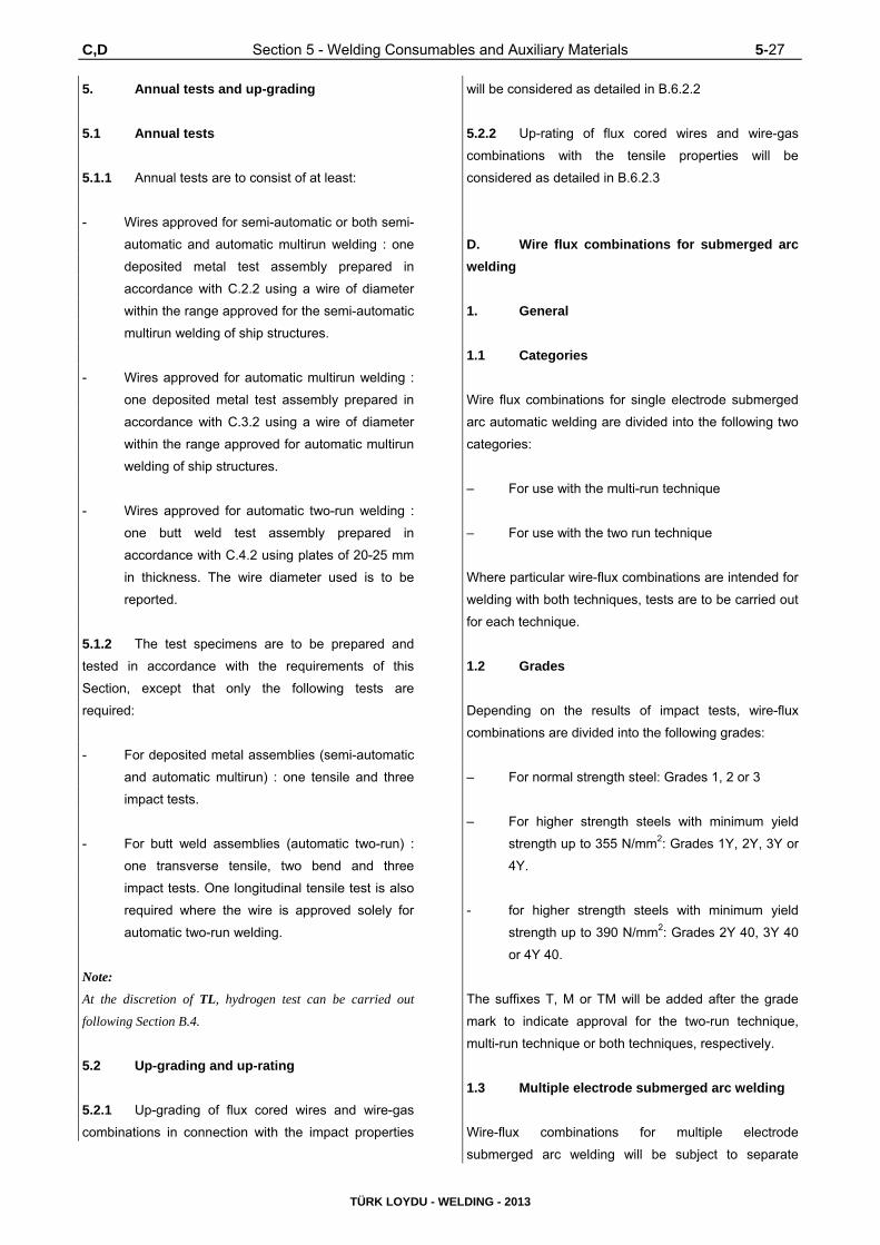
C,D Section 5 - Welding Consumables and Auxiliary Materials 5-27
TÜRK LOYDU - WELDING - 2013
5. Annual tests and up-grading
5.1 Annual tests
5.1.1 Annual tests are to consist of at least:
- Wires approved for semi-automatic or both semi-
automatic and automatic multirun welding : one
deposited metal test assembly prepared in
accordance with C.2.2 using a wire of diameter
within the range approved for the semi-automatic
multirun welding of ship structures.
- Wires approved for automatic multirun welding :
one deposited metal test assembly prepared in
accordance with C.3.2 using a wire of diameter
within the range approved for automatic multirun
welding of ship structures.
- Wires approved for automatic two-run welding :
one butt weld test assembly prepared in
accordance with C.4.2 using plates of 20-25 mm
in thickness. The wire diameter used is to be
reported.
5.1.2 The test specimens are to be prepared and
tested in accordance with the requirements of this
Section, except that only the following tests are
required:
- For deposited metal assemblies (semi-automatic
and automatic multirun) : one tensile and three
impact tests.
- For butt weld assemblies (automatic two-run) :
one transverse tensile, two bend and three
impact tests. One longitudinal tensile test is also
required where the wire is approved solely for
automatic two-run welding.
Note:
At the discretion of TL, hydrogen test can be carried out
following Section B.4.
5.2 Up-grading and up-rating
5.2.1 Up-grading of flux cored wires and wire-gas
combinations in connection with the impact properties
will be considered as detailed in B.6.2.2
5.2.2 Up-rating of flux cored wires and wire-gas
combinations with the tensile properties will be
considered as detailed in B.6.2.3
D. Wire flux combinations for submerged arc
welding
1. General
1.1 Categories
Wire flux combinations for single electrode submerged
arc automatic welding are divided into the following two
categories:
– For use with the multi-run technique
– For use with the two run technique
Where particular wire-flux combinations are intended for
welding with both techniques, tests are to be carried out
for each technique.
1.2 Grades
Depending on the results of impact tests, wire-flux
combinations are divided into the following grades:
– For normal strength steel: Grades 1, 2 or 3
– For higher strength steels with minimum yield
strength up to 355 N/mm2: Grades 1Y, 2Y, 3Y or
4Y.
- for higher strength steels with minimum yield
strength up to 390 N/mm2: Grades 2Y 40, 3Y 40
or 4Y 40.
The suffixes T, M or TM will be added after the grade
mark to indicate approval for the two-run technique,
multi-run technique or both techniques, respectively.
1.3 Multiple electrode submerged arc welding
Wire-flux combinations for multiple electrode
submerged arc welding will be subject to separate

5-28 Section 5 - Welding Consumables and Auxiliary Materials D
TÜRK LOYDU - WELDING - 2013
approval tests. They are to be carried out generally in
accordance with the requirements of this section.
1.4 Mechanical tests on assemblies
Mechanical tests on assemblies with submerged arc
welding for wire/flux approval are given in Table 5.10a.
2. Approval tests for multi run technique
2.1 Grades of steel
Where approval for use with the multi run technique is
requested, deposited metal and butt weld tests are to be
carried out.
For deposited metal test assembly any grade of ship
structural steel may be used.
For butt weld test assembly one of the grades of steel
as listed below for the individual grades of wireflux
combinations shall be used:
- Grade 1 wire-flux combinations : A
- Grade 2 wire-flux combinations : A, B, D
- Grade 3 wire-flux combinations : A, B, D, E
- Grade 1 Y wire-flux combinations : A32, A36
- Grade 2 Y wire-flux combinations : A32, A36,
D32, D36
- Grade 3 Y wire-flux combinations : A32, A36,
D32, D36,
E32, E 36
- Grade 4 Y wire-flux combinations : A32, A36,
D32, D36,
E32, E36,
F32, F 36
- Grade 2 Y 40 wire-flux combinations : A40, D 40
- Grade 3 Y 40 wire-flux combinations : A40, D 40
E 40
- Grade 4 Y 40 wire-flux combinations : A40, D 40,
E40, F 40
2.2 Deposited metal test assembly
2.2.1 Preparation
One deposited metal test assembly is to be prepared as
shown in Fig. 5.10.
Table 5.10a Mechanical tests on assemblies with submerged arc welding for wire / flux approval
M (multi-run technique)
T (two-run technique)
TM (two-run and multi-run technique)
Deposited metal
assembly
Butt weld assembly
Butt weld assembly (minimum thickness)
Butt weld assembly (maximum thickness)
Deposited metal
assembly
Butt Weld Assembly
Multi-run technique
Two-run technique
(Minimum thickness)
(Maximum thickness)
- -
3CV 2 LT
2 TT 4 TB 3 CV
-
2 TT 2 TB 3 CV 1 LT
2 TT 2 TB 3 CV
-
- -
3 CV 1 LT
2 TT 4 TB 3 CV
-
2 TT 2 TB 3 CV
-
2 TT 2 TB 3 CV 1 LT
Symbol Definition: TT: Transverse Tensile Test on the butt weld assembly TB : Transverse Bend Test on the butt weld assembly CV : Charpy-V Impact Test in the axis of the weld LT : Longitudinal Tensile Test in the weld

D Section 5 - Welding Consumables and Auxiliary Materials 5-29
TÜRK LOYDU - WELDING - 2013
Welding is to be carried out in the downhand position,
and the direction of deposition of each run is to alternate
from each end of the plate. After completion of each
run, the flux and welding slag is to be removed.
Between each run the assembly is to be left in still air
until it has cooled to less than 250 °C, but not below 100
°C, the temperature being taken in the centre of the
weld, on the surface of the seam. The thickness of the
layer is to be not less than the diameter of the wire nor
less than 4 mm.
The weld conditions, including amperage, voltage and
rate of travel speed are to be in accordance with the
recommendations of the manufacturer and are to
conform with normal good welding practice for multi-run
welding.
2.2.2 Chemical analysis
At the discretion of TL, the chemical analysis of the
deposited weld metal in this test assembly is to be
supplied by the manufacturer and is to include the
content of all significant alloying elements.
2.2.3 Execution of tests
In accordance with Table 5.10a, the test specimens as
shown in Fig. 5.10 are to be prepared from each test
assembly. Tests are to be performed according to
Section 3 requirements.
2.2.4 Results and requirements
The results of all tests are to comply with the
requirements of Table 5.10b, as appropriate.
2.3 Butt Weld Test Assembly
2.3.1 Preparation
One butt weld test assembly is to be prepared as shown
in Fig. 5.11 in the downhand position by welding
together two plates (20 to 25 mm thick), each not less
than 150 mm in width and sufficient length to allow the
cutting out of test specimens of the prescribed number
and size.
The plate edges are to be prepared to form a single vee
joint, the included angle between the fusion faces being
60° and the root face being 4 mm.
The welding is to be carried out by the multi-run
technique and the welding conditions are to be the
same as those adopted for the deposited metal test
assembly.
The back sealing run is to be applied in the downhand
position after cutting out the root run to clean metal.
After welding the test assembly is not to be subject to
any heat treatment.
Table 5.10b Requirements for deposited metal tests (wire-flux combinations)
Grade Yield stress
N/mm2 minimum
Tensile Strength
N/mm2
Elongation on 50 mm gauge length
(Lo = 5 d) % minimum
Charpy V-notch impact tests
Test Temperature °C
Average Energy
J minimum
1 2 3
305 400 - 560 22 20 0
-20
34 34 34
1Y 2Y 3Y 4Y
375 490 - 660 22
20 0
-20 -40
34 34 34 34
2Y 40 3Y 40 4Y 40
400 510 - 690 22 0
-20 -40
39 39 39

5-30 Section 5 - Welding Consumables and Auxiliary Materials D
TÜRK LOYDU - WELDING - 2013
Table 5.10c Requirements for butt weld tests (wire-flux combinations)
Grade Tensile strength (transverse test)
N/mm2
Charpy V-notch impact tests
Test temperature °C Average energy J minimum
1 2 3
400 20 0
-20
34 34 34
1Y 2Y 3Y 4Y
490
20 0
-20 -40
34 34 34 34
2Y40 3Y40 4Y40
510 0
-20 -40
39 39 39
Fig. 5.11 Multi-run butt weld test assembly
(submerged arc welding)
2.3.2 Radiographic examination
It is recommended that the welded assembly be subject
to a radiographic examination to ascertain if there are
any defects in the weld prior to the preparation of test
specimens.
2.3.3 Execution of tests
The test specimen to be prepared from the welded
assembly are given in Table 5.10a and shown in Fig.
5.11. The tests are to be performed according to the
requirements of Section 3.
2.3.4 Results of tests and requirements
The results of all tensile and impact tests are to comply
with the requirements of Table 5.10c as appropriate.
The position of the fracture in the transverse tensile test
is to be reported.
The bend test specimens can be considered as
complying with the requirements if, after bending, no
crack or defect, having any dimension exceeding 3 mm
can be seen on the outer surface of the test specimen.
3. Approval tests for two run techniques
3.1 Number of test assemblies
Where approval for use with the two-run technique is
requested, two butt weld test assemblies are to be
prepared using the following thicknesses:
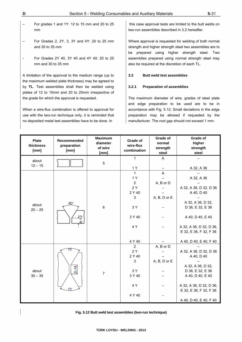
D Section 5 - Welding Consumables and Auxiliary Materials 5-31
TÜRK LOYDU - WELDING - 2013
– For grades 1 and 1Y: 12 to 15 mm and 20 to 25
mm
– For Grades 2, 2Y, 3, 3Y and 4Y: 20 to 25 mm
and 30 to 35 mm
- For Grades 2Y 40, 3Y 40 and 4Y 40: 20 to 25
mm and 30 to 35 mm
A limitation of the approval to the medium range (up to
the maximum welded plate thickness) may be agreed to
by TL. Test assemblies shall then be welded using
plates of 12 to 15mm and 20 to 25mm irrespective of
the grade for which the approval is requested.
When a wire-flux combination is offered to approval for
use with the two-run technique only, it is reminded that
no deposited metal test assemblies have to be done. In
this case approval tests are limited to the butt welds on
two-run assemblies described in 3.2 hereafter.
Where approval is requested for welding of both normal
strength and higher strength steel two assemblies are to
be prepared using higher strength steel. Two
assemblies prepared using normal strength steel may
also be required at the discretion of each TL.
3.2 Butt weld test assemblies
3.2.1 Preparation of assemblies
The maximum diameter of wire, grades of steel plate
and edge preparation to be used are to be in
accordance with Fig. 5.12. Small deviations in the edge
preparation may be allowed if requested by the
manufacturer. The root gap should not exceed 1 mm.
Plate thickness
[mm]
Recommended preparation
[mm]
Maximum diameter of wire [mm]
Grade of wire-flux
combination
Grade of normal
strength steel
Grade of higher
strength steel
about 12 – 15
5
1
1 Y
A
–
–
A 32, A 36
about 20 – 25
6
1 1 Y 2
2 Y 2 Y 40
3
3 Y
3 Y 40
4 Y
4 Y 40
A –
A, B or D – –
A, B, D or E
–
–
–
–
– A 32, A 36
– A 32, A 36, D 32, D 36
A 40, D 40 –
A 32, A 36, D 32, D 36, E 32, E 36
A 40, D 40, E 40
A 32, A 36, D 32, D 36, E 32, E 36, F 32, F 36
A 40, D 40, E 40, F 40
about 30 – 35
7
2 2 Y
2 Y 40 3
3 Y 3 Y 40
4 Y
4 Y 40
A, B or D – –
A, B, D or E
– –
–
–
– A 32, A 36, D 32, D 36
A 40, D 40 –
A 32, A 36, D 32, D 36, E 32, E 36 A 40, D 40, E 40
A 32, A 36, D 32, D 36, E 32, E 36, F 32, F 36
A 40, D 40, E 40, F 40
Fig. 5.12 Butt weld test assemblies (two-run technique)

5-32 Section 5 - Welding Consumables and Auxiliary Materials D
TÜRK LOYDU - WELDING - 2013
Each butt weld is to be welded in two runs, one from
each side, using amperages, voltages and travel
speeds in accordance with the recommendations of
manufacturer and normal good welding practice.
After completion of the first run, the flux and welding
slag are to be removed and the assembly is to be left in
still air until it has cooled to 100°C, the temperature
being taken in the centre of the weld, on the surface of
the seam. After welding, the test assemblies are not to
be subjected to any heat treatment.
3.2.2 Radiographic examination
It is recommended that the welded assemblies are
subjected to radiographic examination to ascertain if
there are any defects in the weld prior to the preparation
of test specimens.
3.2.3 Execution of tests
The test specimens indicated in Table 5.10a and shown in
Fig. 5.13 are to be prepared from each test assembly.
Tests are to be performed according to Section 3
requirements. The Charpy V-notch impact test specimens
are to be machined from each welded assembly from the
positions and with the orientations shown in Fig. 5.14.
3.2..4 Results of tests and requirements
The results of all tensile and impact tests are to comply
with the requirements of table 5.10b and 5.10c as
appropriate. The position of fracture in the transverse
tensile test is to be reported. The bend test specimens
can be considered as complying with the requirements
if, after bending, no crack or defect having any
dimensions exceeding 3 mm can be seen on the outer
surface of the test speciment.
3.2.5 Chemical analysis
The chemical analysis of the weld metal is to be
supplied by the manufacturer, and is to include the
content of all significant alloying elements.
4. Annual tests - upgrading
4.1 Annual tests
All establishments where approved wire/flux
combinations are manufactured shall be subject to
annual inspection.
Fig. 5.13 Test specimens
Fig. 5.14 The Charpy V-notch impact test specimen
Annual tests are to consist of at least the following:
4.1.1 Multirun technique: on deposited metal assembly
and tests: 1 tensile and 3 impact tests.
4.1.2 Two-run technique: one butt weld assembly with
20 mm minimum thickness plate and tests: 1 transverse
tensile, 2 transverse bends and 3 impact tests. One
longitudinal tensile test specimen is also to be prepared
where the wire-flux combination is approved solely for

D,E Section 5 - Welding Consumables and Auxiliary Materials 5-33
TÜRK LOYDU - WELDING - 2013
the two-run technique.
The assemblies are to be prepared and tested in
accordance with the requirements for initial approval.
Where a wire-flux combination is approved for welding
both normal strength and higher strength steel, the latter
steel is to be used for the preparation of the butt weld
assembly required by 4.1.2.
4.2 Upgrading and rating
4.2.1 Upgrading of wire-flux combinations in
connection with the impact properties will be considered
as detailed in B.6.2.2, and for wire-flux combinations
approved for two runs welding, a butt-weld in the
maximum thickness approved is to be made and
sampled for Charpy-V testing in accordance with 3.2.3.
4.2.2 Uprating of wire-flux combinations in
connection with the tensile properties will be considered
as detailed in 6.2.3.
E. Consumables for use in eletroslag and
electrogas vertical welding
1. General
1.1 The requirements for the two-run technique as
detailed in D are applicable for the approval of special
consumables used in electro-slag and electro-gas
vertical welding with or without consumable nozzles
except as otherwise required by the following
requirements especially as regards the number and kind
of the test-pieces used for the mechanical tests and
taken from the butt welded assemblies.
1.2 For Grades 1Y, 2Y, 3Y, 4Y, 2Y40, 3Y40 and
4Y40 approval of the consumables may be restricted for
use only with specific types of higher strength steel.
This is in respect of the content of grain refining
elements, and if general approval is required, a niobium
treated steel is to be used for the approval tests.
1.3 For these special welding consumables, the
prescription 5.A4.1 may not be entirely applicable for
technical reasons.
Where approval is requested for welding of both normal
strength and higher strength steel two assemblies are to
be prepared using higher strength steel. Two
assemblies prepared using normal strength steel may
also be required at the discretion of each TL.
2. Butt weld tests
2.1 Preparation of test assemblies
Two butt weld test assemblies are to be prepared, one
of them with plates 20/25 mm thick, the other with plates
35/40 mm thick or more. The grade of the steel to be
used for each one of these assemblies must be
selected according to the requirements given in the Fig.
5.12 for two-run submerged arc welding.
The chemical composition of the plate, including the
content of grain refining elements is to be reported.
The welding conditions and the edge preparation are to
be those recommended by the welding consumable
manufacturer and are to be reported.
2.2 Radiographic examination
It is recommended that the welded assemblies be
subjected to a radiographic examination to ascertain if
there are any defects in the weld prior to the preparation
of test specimens.
2.3 Test series
Each assembly shall be cut to give test specimens
according to Fig. 5.15.
The length of the assembly should be sufficient to allow
the selection of all the test specimens:
– 2 longitudinal tensile test specimens with their
axis at the centre of the weld.
– 2 transverse tensile test specimens.
– 2 side bend test specimens.
– 2 sets of 3 Charpy-V notch impact test
specimens in accordance with Fig. 5.15:

5-34 Section 5 - Welding Consumables and Auxiliary Materials E
TÜRK LOYDU - WELDING - 2013
set with the notch in the axes of the weld,
set with the notch at 2 mm from the fusion line in
the deposited metal.
– 2 macro-sections to the weld (towards the middle
of the weld and towards one end).
2.4 Results to be obtained
The results of the tensile, bend and impact tests are to
comply with the requirements of paragraph D.3 (two-run
welding) for the class of filler product in question.
3. Annual tests and up-grading
3.1 All factories which manufacture approved
consumables for use in electroslag and electrogas
welding must be subject to an annual inspection and
tests in accordance with 5 A.3.2, A.7.4 and 7.5)
Fig. 5.15 Electroslag and electrogas butt weld test assembly

E,F Section 5 - Welding Consumables and Auxiliary Materials 5-35
TÜRK LOYDU - WELDING - 2013
3.2 One test assembly must be prepared from
plates 20/25 mm thick, and tested as indicated in E.2.
The following specimens are to be selected:
– 1 longitudinal tensile specimen from the axis of
the weld,
– 1 transverse tensile specimen,
– 2 side bend specimens,
– 3 Charpy-V specimens notched at the centre of
the weld (position 1 Fig. 5.15),
– 3 Charpy-V specimens cut out transverse to the
weld with their notches at 2 mm from the fusion
line, in the weld,
– Macro section.
3.3 The results to be obtained should meet the
requirements given in D.3 (two-run welding) for the
class of the consumables in question.
3.4 Upgrading and uprating
Upgrading and uprating will be considered only at the
manufacturers request, at the time of annual testing.
Generally, for this purpose, full tests from butt weld
assemblies as indicated in E.2 will be required,
irrespective of the other tests requested if the
concerned consumable is also approved (and possibly
upgraded or uprated) according to C or D.
F. Approval of Welding Consumables for High
Strength Quenched and Tempered Steels for
Welded Structures
1. General
1.1 Scope
1.1.1 These requirements supplements the previous
parts in this section and give the conditions of approval
and inspection of welding consumables used for high
strength quenched and tempered or TMCP steels for
welded structures according to UR W16 (TL Rules,
Chapter 2, Section 3, C) with yield strength levels from
420 N/mm2 up to 690 N/mm2 and impact grades A, D, E
and F.
Where no special requirements are given, those of
previous parts in this section apply in analogous manner.
1.1.2 The welding consumables preferably to be
used for the steels concerned are divided into several
categories as follows :
- Covered electrodes for manual welding,
- Wire-flux combinations for multirun (2)
submerged arc welding,
- Solid wire-gas combinations for arc welding
(including rods for gas tungsten arc welding),
- Flux cored wire with or without gas for arc
welding.
1.2 Grading, Designation
1.2.1 Based on the yield strength of the weld metal,
the welding consumables concerned are divided into six
(yield) strength groups :
- Y42 - for welding steels with minimum yield
strength 420 N/mm2
- Y46 - for welding steels with minimum yield
strength 460 N/mm2
- Y50 - for welding steels with minimum yield
strength 500 N/mm2
- Y55 - for welding steels with minimum yield
strength 550 N/mm2
- Y62 - for welding steels with minimum yield
strength 620 N/mm2
(2) Wire-flux combinations for single or two-run
technique are subject to special consideration of
TL.1,0% Mn, 0,03 % P, 0,03 % S.

5-36 Section 5 - Welding Consumables and Auxiliary Materials F
TÜRK LOYDU - WELDING - 2013
- Y69 - for welding steels with minimum yield
strength 690 N/mm2
1.2.2 Each of the six (yield) strength groups is further
divided into three main grades in respect of charpy V-
notch impact test requirements (test temperatures):
- Grade 3, test temperature -20°C
- Grade 4, test temperature -40°C
- Grade 5, test temperature -60°C
1.2.3 Analagously to the designation scheme used in
previous parts incthis section the welding consumables
for high strength quenched and tempered steels are
subject to classification designation and approval as
follows:
- According to F.1.2.2 with the quality grades 3,4
or 5
- With the added symbol Y and an appended code
number designating the minimum yield strength
of the weld metal corresponding 1.2.1: Y42, Y46,
Y50, Y55, Y62 and Y69.
- With the added symbol H10 (HH) or H5 (HHH)
for controlled hydrogen content of the weld
metal,
- With the added symbol S (= Semi-automatic) for
semi-mechanised welding,
- With the added symbol M designating multirun
technique *) (and is applicable only to welding
consumables for fully mechanised welding), *)
see footnote on page 2
1.2.4 Each higher quality grade includes the one (or
those) below Grade A... and D... steels acc. to UR W16
(TL Rules, Chapter 2, Section 3, C) are to be welded
using welding consumables of at least quality grade 3,
grade E... steels using at least quality grade 4 and
grade F... steels using at least quality grade 5., see the
following table :
Consumable Grade Steel Grades covered
3Y.. 4Y.. 5Y..
D.. and A.. E.., D.. and A.. F.., E.., D.. and A..
Welding consumables approved with grades ..Y42,
..Y46 and ..Y50 are also considered suitable for welding
steels in the two strength levels below that for which
they have been approved. Welding consumables
approved with grades ..Y55, ..Y62 and ..Y69 are also
considered suitable for welding steels in the strength
level below that for which they have been approved.
TL may, in individual cases, restrict the range of
application in (up to) such a way, that approval for any
one strength level does not justify approval for any other
strength level.
1.3 Manufacture, testing and approval
procedure
1.3.1 Manufacturer’s plant, production methods and
quality control measures shall be such as to ensure
reasonable uniformity in manufacture, see also previous
parts in this section.
1.3.2 Testing and approval procedure shall be in
accordance with previous parts in this section and 2
and 3 and as required in previous parts in this section
for the individual categories (types) of welding
consumables mentioned in F.1.1.2 above.
2. Testing of the weld metal
2.1 For testing the deposited weld metal, test
pieces analogous to those called for in, sections B,C,D
respectively shall be prepared, depending on the type of
the welding consumables (and according to the welding
process). the base metal used shall be a fine-grained
structural steel compatible with the properties of the
weld metal, or the side walls of the weld shall be
buttered with a weld metal of the same composition.
2.2 The chemical composition of the deposited
weld metal shall be determined and certified in a
manner analogous to that prescribed in section B.2.2.
The results of the analysis shall not exceed the limit
values specified in the standards or by the
manufacturer, the narrower tolerances being applicable
in each case.

F Section 5 - Welding Consumables and Auxiliary Materials 5-37
TÜRK LOYDU - WELDING - 2013
2.3 Depending on the type of the welding
consumables (and according to the welding process),
the test specimens prescribed in sections B.4.1 and
5.B.2.1, D.2, C.2 or C.3 respectively shall be taken from
the weld metal test pieces in a similar manner.
2.4 The mechanical properties must meet the
requirements stated in Tables 5.11a and 5.11b The
provisions of previous parts in this section apply in
analogous manner to the performance of the tests,
including in particular the maintenance of the test
temperature in the notched bar impact test and the
carrying out of results.
3. Testing on welded joints
3.1 Depending on the type of the welding
consumables (and according to the welding process),
the testing on the welded joints shall be performed on
butt-weld test pieces in analogous manner to, sections
B,C,D, or E respectively.
3.2 Depending on the type of the welding
consumables (and according to the welding process),
the butt-weld test pieces called for in 3.1 shall be
welded in a manner analogous to that prescribed in UR
W17 (TL Rules, Chapter 3, Section 5 and Section 12,
E). The base metal used shall be a high-strength fine-
grained structural steel with an appropriate minimum
yield strength and tensile strength and compatible with
the added symbol for which application is made.
3.3 Depending on the type of the welding
consumables (and according to the welding process),
the test specimens described in previous parts in this
section shall be taken from the butt-weld test pieces.
3.4 The mechanical properties must meet the
requirements stated in Table 5.11c. The provisions of
previous parts in this section apply in analogous
manner to the performance of the tests, including in
particular the maintenance of the test temperatures in
the notched bar impact test and the requirements
regarding the retest specimens.
Table 5.11a Required toughness properties of the weld metal
Qality grade Test temperature °C Minimum notch impact energy J (1)
3 -20 Y42: 47 Y46: 47 Y50: 50 Y55: 55 Y62: 62 Y69: 69
4 -40
5 -60
(1) Charpy V-notch impact test specimen, mean value of three specimens; for requirements regarding minimum individual values and retests, see UR W17 (TL Rules, Chapter 3, Section 5 and Section 12, E), section 3.3.2
Table 5.11b Required strength properties of the weld metal
Symbols added to quality grade
Minimum yield strength or 0.2% proof stress
[N/mm2]
Tensile Strength (1) [N/mm2]
Minimum elongation [%]
Y42 Y46 Y50 Y55 Y62 Y69
420 460 500 550 620 690
530-680 570-720 610-770 670-830 720-890 770-940
20 20 18 18 18 17
(1) The tensile strength of the weld metal may be up to 10% below the requirements, provided that the results obtained with the transverse tensile specimens taken from the welded joints meet the minimum tensile strength requirements stated in Table 3. The elongation is to be stated in the test report.
Note: For welding very large plate thicknesses where the “supporting effect” of the base material on either side of the weld no longer applies and the tensile strength of the weld metal also determines the tensile strength of the welded joint, it may be necessary, when applying footnote (1), to choose welding consumables of the next higher strength category (next higher added Symbol).

5-38 Section 5 - Welding Consumables and Auxiliary Materials F,G
TÜRK LOYDU - WELDING - 2013
Table 5.11c Required properties of welded joints
Quality grade Added
symbol
Minimum tensile
strength [N/mm2]
Minimum notch impact
energy, test
temperature
Minimum bending
angle (1)
Bend ratio
D/t (2)
3 to 5 accordance with
Table 11.a
Y42 530
Depending on the quality
grade & yield strength in
accordance Table 11.a
120°
4
Y46 570 4
Y50 610 4
Y55 670 5
Y62 720 5
Y69 770 5
(1) Bending angle attained before the first incipient crack, minor pore exposures up to a maximum length of 3mm allowed.
(2) D = Mandrel diameter, t = specimen thickness
3.5 Where the bending angle required in Table
5.11c is not achieved, the specimen may be considered
as fulfilling the requirements, if the bending elongation
on a gauge length length Lo fulfills the minimum
elongation requirements stated in Table 5.11b. The
gauge length Lo = Ls + t (Ls = width of weld, t =
specimen thickness), see sketch below.
4. Hydrogen test
4.1 The welding consumables, other than solid
wire-gas combinations, shall be subjected to a hydrogen
test in accordance with the mercury method to ISO
3690, or any other method such as the gas
chromatographic method which correlates with that
method, in respect of cooling rate and delay times
during preparation of the weld samples, and the
hydrogen volume determinations.
4.2 The diffusible hydrogen content of the weld metal
determined in accordance with the provisions of section
B.4 shall not exceed the limits given in Table 5.11d.
5. Annual repeat test
The annual repeat tests specified in UR W 17 shall
entail the preparation and testing of weld metal test
pieces as prescribed in 2. In special cases, TL may
require more extensive repeat tests.
Table 5.11d Allowable diffusible hydrogen content
Yield
strength
group
Hydrogen
symbol
Maximum hydrogen
content cm3/ 100 g
deposited weld metal
Y42
Y46
Y50
H 10 (HH) 10
Y55
Y62
Y69
H 5 (HHH) 5
G. Welding Consumables and Auxiliary
Materials for Steels Tough at Subzero Temperatures
1. General
1.1 The following provisions apply to welding
consumables and auxiliary materials for welding of
steels tough at subzero temperatures in accordance
with the TL Chapter 2 - Material governing the
fabrication of vessels, pipelines, etc. for liquefied gases.

G Section 5 - Welding Consumables and Auxiliary Materials 5-39
TÜRK LOYDU - WELDING - 2013
Note:
According to TL Chapter 2, Materials, the steels tough at
subzero temperatures used in shipbuilding fall into three
categories: low-alloy carbon-manganese steels, nickel alloy
steels and austenitic steels. The following paragraphs are
therefore concerned with welding consumables and auxiliary
materials for these three categories of materials. Other such
products are to be treated in analogous manner; for
aluminium alloys, see Section 8.
1.2 Depending on their nature and properties (type
of alloy), welding consumables and auxiliary materials
for welding of steels tough at subzero temperatures are
classified and approved in the same way as those for
high-strength (quenched and tempered) structural steels
in accordance with F. or those for (austenitic) stainless
steels or, where applicable, nickel alloy steels tough at
subzero temperatures in accordance with I. No special
indication of suitability for low-temperature service is
given (except with the quality grade in accordance with
F.); individual suitability for low-temperature service
(test temperature for the notched bar impact test and
proven notch impact energy) is indicated in the approval
certificate. In general, the minimum service (design)
temperature is 5 °C above this test temperature.
2. Testing of the Weld Metal
2.1 Testing of the weld metal shall be carried out in
accordance with the nature of the welding consumables
and auxiliary materials, as described in F. and I. Unless
otherwise stipulated in a particular case, the test
temperatures for the notched bar impact test stated in
these provisions shall be replaced by the test
temperatures shown in Table 5.12.
Table 5.12 Minimum design temperatures and test temperatures for the notched bar impact test
Welding consumables and
auxiliary materials for:
References to Rules and
Standards relating to Materials
Minimum
design
temperature
[°C]
Test temperature for
the notched bar
impact test [°C]
Fine grain structural steels for
ammonia liquefied under pressure
in accordance with Chapter 2 -
Material, Section 3, F. Table 3.16 0 - 20
High-strength (QT) fine grain
structural steels with nominal yield
strengths of 420 to 690 N/mm2
in accordance with Chapter 2 -
Material, Section 3 F. Table 3.17 0 - 20
Other fine grain structural steels with
nominal yield strengths of up to 355
N/mm2
e.g. to; EN 10028 Part 3 -45(1)
5° below minimum
design temperature,
but not above -20°C
Nickel steels with:
0,5% nickel
1,5% nickel
3,5% nickel
5% nickel
9% nickel
Steels conforming to EN 10028 Part 4 13MnNi6-3
15NiMn6
12Ni14
12Ni19
X8Ni9, X7Ni9
-55
-60 (2)
-90 (2)
-105 (2) (3)
-165
-60
-65 (2)
-95 (2)
-110 (2) (-196) (3)
-196
Austenitic steels
e.g. to EN........(AISI)
X2CrNi19-11/1.4306 (304L)
X2CrNiMo17-13-2/1.4404 (316 L)
X6CrNiTi18-10/1.4541 (321)
X6CrNiNb18-10/1.4550 (347)
-165 - 196
(1) TL may approve lower design temperatures (down to a maximum - 55°C) provided that corresponding properties are demonstrated in the
approval test.
(2) A lower design temperature may be approved by TL for QT steels with a 1,5 %, 3,5 % and 5 % nickel content; in these instances TL will
specify the test temperatures.
(3) Steel with a 5 % nickel content may be approved for a minimum design temperature of - 165°C subject to the provisions stipulated in the
Chapter 2 - Material, Section 3, F., Table 3.15, footnote (1); the test temperature is then - 196 °C.

5-40 Section 5 - Welding Consumables and Auxiliary Materials G,H
TÜRK LOYDU - WELDING - 2013
2.2 The requirements applicable to the strength
and elongation of the weld metal are determined by
those applying to the base material; see Chapter 2,
Materials, Section 3, F., Section 4, D., Section 5, F. and
Section 6, E. If particular base materials are welded with
dissimilar welding consumables and auxiliary materials
with strength values below those of the base material
(e.g. in welding of 9 % nickel steel), the strength values
used in the design calculations for the components shall
apply. Unless otherwise stipulated, the minimum notch
impact energy values at the test temperatures shown in
Table 5.12 shall be 47 J (mean value) and 39 J (lowest
individual value).
3. Testing on Welded Joints
The testing on the welded joints shall be performed in
accordance with the nature of the welding consumables
and auxiliary materials as described in F. and I. In the
case of welding consumables and auxiliary materials for
nickel alloy steels, the welded joints shall be made with
the base material for which approval has been solicited.
In the case of such products for (low-alloy) carbon-
manganese steels and austenitic steels, a base material
of similar composition may be used. In all other
respects, 2.1 and 2.2 apply in analogous manner.
4. Hydrogen Test
If a hydrogen test is stipulated for the welding consumables
and auxiliary materials in question (e.g. according to F.4), it
shall be performed in this case too. The requirements
stipulated for each individual case apply.
5. Annual Repeat Tests
The annual repeat tests specified in A.3.1 shall entail
the preparation and testing of weld metal test pieces as
prescribed in 2. TL may require more extensive repeat
tests (see A.3.2, A.7.4 and A.7.5).
H. Welding Consumables and Auxiliary
Materials for High-Temperature Steels
1. General
1.1 The following provisions apply to welding
consumables and auxiliary materials for welding of high-
temperature steels in accordance with the TL Rule
Chapter 2 - Material governing the fabrication of steam
boilers, pressure vessels, pipelines, etc. with high
service temperatures.
Note:
Under TL Chapter 2, Materials, this essentially applies to the
carbon-manganese steels P235GH (HI), P265GH (H II),
P295GH (17Mn4), P355GH (19Mn6), the molybdenum alloy
steel 16Mo3 (15Mo3) and the chromium-molybdenum alloy
steels 13CrMo4-5 (13CrMo4-4), 10CrMo9-10 (10CrMoI-10 )
and 11CrMo9-10 in accordance with EN 10028 Part 2. The
following paragraphs are therefore concerned with welding
consumables and auxiliary materials for these steels. Other
such products are included if they can be classed among the
materials also covered by the approval as shown in Table 5.13.
Other welding consumables and auxiliary materials for other
high-temperature steels are to be treated in analogous manner.
1.2 Welding consumables and auxiliary materials
for high-temperature steels are classified into the quality
grades shown in Table 5.13 according to their chemical
composition (type of alloy) and mechanical (strength)
characteristics and approved according to these grades.
The testing and approval of a steel in the left-hand
columns of Table 5.13 encompasses the steel(s) in the
right-hand columns. The different high-temperature
strength properties are to be borne in mind. The table
applies in analogous manner to the corresponding
grades of forgings and steel castings
1.3 Welding consumables and auxiliary materials
for components which are to undergo post-weld heat
treatment must be tested and approved separately for
the untreated condition and for each heat-treated
condition. In general, the relevant conditions are:
U = Untreated (as-welded condition) and
S = Annealed to relieve stresses.
In special cases, normalizing (N) or quenching and
tempering (V) may be necessary. The annealing
temperatures and times shall be those applicable to the
subsequent heat treatment of the components accord-
ing to the standards, material data sheets, etc. Unless
more precise data are given in these documents, the
annealing temperatures and times specified in Section
9, Table 9.2 may be used

H Section 5 - Welding Consumables and Auxiliary Materials 5-41
TÜRK LOYDU - WELDING - 2013
2. Testing the Weld Metal
2.1 The testing of the weld metal shall be
performed according to the nature of the welding
consumable or auxiliary material (and, where
applicable, according to the welding process) using test
pieces and specimens in analogous manner to the
provisions of B.2,In addition, for determining the 0,2 %
proof stress at the maximum application temperature
and at intermediate stages according to 2.3 two further
round tensile specimens are to be taken from each test
piece and tested. For this purpose, the test pieces shall
be made correspondingly larger.
2.2 The chemical composition of the deposited
weld metal shall be determined and certified in a
manner analogous to that prescribed in B.2.2. The
results of the analysis shall not exceed the limit values
specified in the standards (e.g. DIN 1599, EN ISO
21952 of EN ISO 17634) or by the manufacturer, the
narrower tolerances being applicable in each case.
2.3 As a minimum requirement, the test
specimens prescribed in B.2.3,shall be taken from the
weld metal test pieces and tested at room temperature.
In addition, to determine the yield strength or the 0,2 %
proof stress at the highest application temperature and
at a second test temperature 100°C lower, two further
round tensile test specimens shall be taken from the
test pieces and tested.
TL may require further specimens to be taken and tests
to be performed, e.g. determination of the 1,0 % proof
stress, creep tests, notched bar impact tests on
specimens subjected to ageing treatment or
embrittlement tests.
2.4 The mechanical properties at room
temperature must meet the requirements stated in
Table 5.14 while the yield strength or the 0.2 % proof
stresses at elevated temperature must conform to Table
5.15. If further tests are demanded by TL, the
requirements will be stipulated separately on a case-by-
case basis. The provisions of A.7.6 and B.2.4, apply in
analogous manner to the performance of the tests and
any retests which may be required.
Table 5.13 Welding consumables and auxiliary materials for high-temperature steels
Quality grade
Testing and approval relating to steel (1) Steels also covered by the approval (2)
Designation Material No Designation (1) Material No.
235GH P235GH 1.0345 - -
265GH P265GH 1.0425 P235GH 1.0345
295GH P295GH 1.0481 P235GH P265GH
1.0345 1.0425
355GH P355GH 1.0473 P235GH P265GH P295GH
1.0345 1.0425 1.0481
16Mo3 16Mo3 1.5415
P235GH P265GH P295GH P355GH
1.0345 1.0425 1.0481 1.0473
13CrMo4-5 13CrMo4-5 1.7335 16Mo3 1.5415
10CrMo9-10 10CrMo9-10 1.7380 16Mo3
13CrMo4-5 1.5415 1.7335
11CrMo9-10 11CrMo9-10 1.7383 16Mo3
13CrMo4-5 10CrMo9-10
1.5415 1.7335 1.7380
(1) Steel grades in accordance with TL’s Rule Chapter 2 - Material or conforming to EN 10028. (2) Steel grades in accordance with TL’s Rule Chapter 2 - Material or conforming to EN 10028 as well as other grades of
forgings and steel castings.

5-42 Section 5 - Welding Consumables and Auxiliary Materials H
TÜRK LOYDU - WELDING - 2013
Table 5.14 Required properties of the weld metal at room temperature (+20°C)
Quality grade
Minimum yield strength or 0,2% proof stress (1) ReL or Rp0,2
[N/mm2]
Minimum tensile strength
Rm [N/mm2]
Minimum elongation
A5
[%]
Minimum notch impact energy (2)
[J]
235GH 265GH
285 480 22
47 (33)
295GH 355GH
360 520 22
16Mo3 355 510 22
13CrMo4-5 355 510 20
10CrMo9-10 11CrMo9-10
400 520 18
(1) The lower yield strength ReL shall apply. Where the yield strength is not clearly defined, the 0,2 % proof stress (Rp0 2) must be used.
(2) Mean value of three specimens; for minimum individual values ( ) and retests, see B.2.4 and 2.5 as well as H.2.4.
Table 5.15 Yield strength resp. 0,2% proof stress at elevated temperatures
Quality grade
Minimum yield strength resp. 0,2% proof stress (1) at a temperatures °C
50 100 150 200 250 300 350 400 450 500
[N/mm2]
235GH 206 190 180 170 150 130 120 110 - -
265GH 234 215 205 195 175 155 140 130 - -
295GH 272 250 235 225 205 185 170 155 -
355GH 318 290 270 255 235 215 200 180 - -
16Mo3 - - - 215 200 170 160 150 145 140
13CrMo4-5 - - - 230 220 205 190 180 170 165
10CrMo9-10 - - - 215 200 170 160 150 145 140
11CrMo9-10 - - - - 255 235 225 215 205 195
(1) The lower yield strength (ReL) shall apply. Where the yield strength is not clearly defined, the 0,2% proof stress (Rp0,2) must be used.
3. Testing on Welded Joints
3.1 Depending on the nature of the welding con-
sumables and auxiliary materials (and on the welding
process concerned), the testing on the welded joints
shall be performed on butt-weld test pieces in analo-
gous manner to the provisions of B.3,
3.2 The butt-weld test pieces shall be prepared in
analogous manner to the procedures described in B.3.2,
taking Table 5.14 into account. Wherever possible, the
base material should be a high-temperature steel
corresponding to the quality grade in question.
3.3 Depending on the welding process, the test
specimens described in B.3.3,shall be taken from the
butt-welded test pieces, unless otherwise specified.

H,I Section 5 - Welding Consumables and Auxiliary Materials 5-43
TÜRK LOYDU - WELDING - 2013
3.4 The mechanical characteristics of the welded
joint must meet the requirements for the weld metal
stated in Table 5.14; except in the case of the yield
strength. The provisions of A.7.6, B.3.4 apply in
analogous manner to the performance of the tests and
any retests which may be required.
4. Hydrogen Test
If a hydrogen test is required, it shall be performed in
accordance with B.4. The diffusible hydrogen content shall
not exceed 10 ml per 100 g of deposited weld metal.
5. Testing for Hot Cracks
If testing for hot cracks is required, this shall be
performed in accordance with B.5 or the relevant
standards (e.g. EN ISO 17641-2).
6. Annual Repeat Tests
6.1 The annual repeat tests specified in A.3.1 shall
entail the preparation and testing of weld metal test
pieces as prescribed in 2. TL may require more
extensive repeat tests (see A.3.2, A.7.4 and A.7.5).
6.2 The annual repeat tests shall be performed
according to the prescribed scope for both the untreated
condition and the various (approved) heat
treated conditions (see 1.3).
I. Austenitic and Austenitic-Ferritic Welding
Consumables and Auxiliary Materials for Stainless
Steels, Non-Magnetic Steels and Nickel Alloy Steels
Tough at Subzero Temperatures
1. General
1.1 The following provisions apply to welding
consumables and auxiliary materials for welding of
stainless (austenitic) steels and steel castings, plates
clad with these materials and joints of these materials
with unalloyed and low-alloy (hull) structural steels.
They also apply to welding consumables and auxiliary
materials for welding of non-magnetic steels, nickel
alloy steels tough at subzero temperatures and other,
similar steels. Austenitic welding consumables and
auxiliary materials for clad welding and for joining
difficult weldable (ferritic) materials are to be treated in
analogous manner.
Notes:
In (tanker) shipbuilding, the current practice is to use, in the
main, the (austenitic or austenitic-ferritic) molybdenum alloy
stainless steels listed in the three left-hand columns of Table
5.21. For equipment components, use is also made of, among
others, steels of types 5CrNil8-10 (mat. no. 1.4301, AISI 304)
and X6CrNiTi18-10 (mat. no. 1.4541, AISI 321). The
following paragraphs therefore relate to welding
consumables and auxiliary materials for these base materials
including their joints with hull structural steels. Furthermore,
the welding consumables and auxiliary materials for which
TL had already granted approval have also been included.
Welding consumables and auxiliary materials for other base
materials should, where applicable, be allocated to the
appropriate categories and treated in analogous manner.
Inert gases with 1 to 3 % of oxygen added or those with a
maximum o f 2 , 5 % CO2 added can be used as shielding
gases for welding austenitic welding consumables in the
range of application specified in 1.1. Those inert gases with a
high level of nitrogen added can be used for steels which
contain nitrogen. Gas mixtures of the type M 21 (see Table
5.8) with a maximum o f 1 8 % of CO2 added may only be
used with slag-forming flux-cored wire electrodes. Approvals
for (flux-cored) wire-gas combinations are also granted
accordingly.
1.2 Welding consumables and auxiliary materials
for welded joints uniting (austenitic or austenitic-ferritic)
stainless steels to one another are classified into the
quality grades shown in Table 5.18 according to the
chemical composition (material no.) and mechanical
(strength) characteristics of the base materials to be
welded. The testing and approval of a steel in the left-
hand column of the table encompasses the steel(s) in
the right-hand column, subject to separate consideration
of the corrosion conditions in each case. The table
applies in analogous manner to the corresponding
grades of forgings and steel castings.

5-44 Section 5 - Welding Consumables and Auxiliary Materials I
TÜRK LOYDU - WELDING - 2013
Table 5.16 Austenitic welding consumables and auxiliary materials for welding of stainless steel
Quality
grade
Testing and approval relating to steel Steels also covered by the approval
Designation Material No./AISI Designation Material No./AISI
4301 X5CrNi18-10 1.4301/304 - -
4306 X2CrNi19-11 1.4306/304 L X5CrNi18-10 C2CrNi18-9 GX6CrNi18-9
1.4301/304 1.4307/3047L 1.4308/-
4307 X2CrNi18-9 1.4307/304 L X5CrNi1810 1.4301/304
4404 X2CrNiMo17-13-2 1.4404/316 L
X5CrNi18-10 X2CrNi19-11 GX6CrNi18-9 X5CrNiMo17-12-2 GX6CrNiMo18-9
1.4301/304 1.4306/304L 1.4308/- 1.4401/316 1.4408/-
4429
X2CrNiMoN17-13-3
1.4429/316LN
X2CrNiN18-10 X5CrNiMo17-12-2 X2CrNiMo17-13-2 X2CrNiMoN17-12-2 GX6CrNiMo18-9 X2CrNiMo18-14-3 X5CrNiMo17-13-3 X6CrNiMoTi17-12-2 X10CrNiMoTi18-12 X6CrNiMoNb17-12-2 X10CrNiMoNb18-12
1.4311/303 LN 1.4401/316 1.4404/316 L 1.4406/316 LN 1.4408/- 1.4435/316 L 1.4436/316 1.4571/316 Ti 1.4573/- 1.4580/316 Cb 1.4583/318
4435
X2CrNiMo18-14-3
1.4435/316 L
X5CrNi18-10 X2CrNi19-11 GX6CrNi18-9 X5CrNiMo17-12-2 X2CrNiMo17-13-2 GX6CrNiMo18-9
1.4301/304 1.4306/304L 1.4308/- 1.4401/316 1.4404/316L 1.4408/-
4438
X2CrNiMo18-16-4
1.4438/317L
X5CrNiMo17-12-2 X2CrNiMo17-13-2 X2CrNiMo18-14-3 X5CrNiMo17-13-3
1.4401/316 1.4404/316L 1.4435/316L 1.4436/316
4439
X3CrNiMoN17-13-5
1.4439/(317LN)
X2CrNiMoN17-12-2 X2CrNiMoN17-13-3 X2CrNiMo18-16-4 GX2CrNiMoN17-13-4 GX6CrNiMo17-13 X5CrNiMo17-13
1.4406/316 LN 1.4429/316 LN 1.4438/317 L 1.4446/- 1.4448/- 1.4449/317
4462
X2CrNiMoN22-5
1.4462/-
X8CrNiMo27-5 X6CrNiMo24-8-2 X4CrNiMoNb25-7
1.4460/329 1.4463/- 1.4582/329
4550
X6CrNiNb18-10
1.4550/347
X5CrNi18-10 X2CrNi19-11 GX6CrNi18-9 X6CrNiTi18-10 GX7CrNiNb18-9
1.4301/304 1.4306/304L 1.4308/- 1.4541/321 1.4552/-
4571
X6CrNiMoTi17-12-2
1.4571/316Ti
X5CrNi18-10 X2CrNi19-11 GX6CrNi18-9 X5CrNiMo17-12-2 X2CrNiMo17-13-2 GX6CrNiMo18-9 X2CrNiMo18-14-3 X5CrNiMo17-13-3 X6CrNiTi18-10 X6CrNiNb18-10 GX7CrNiNb18-9 X10CrNiMoTi18-12 X6CrNiMoNb17-12-2 GX7CrNiMoNb18-2 X10CrNiMoNb18-12
1.4301/304 1.4306/304 L 1.4308/- 1.4401/316 1.4404/316 1.4408/- 1.4435/316 L 1.4436/316 1.4541/321 1.4550/347 1.4552- 1.4573/- 1.4580/316 Cb 1.4581/-1.4583/318

I Section 5 - Welding Consumables and Auxiliary Materials 5-45
TÜRK LOYDU - WELDING - 2013
Table 5.17 Austenitic welding consumables and auxiliary materials for welding of non-magnetic
stainless steels
Quality
grade
Testing and approval relating to steel Steels also covered by the approval
Designation Mat. No. Designation Mat. No.
3954 X2CrNiMnMoNNb21-16-5-3 1.3964
X4CrNiMnMoN19-13-8
X2CrNiMoN22-15
X2CrNiMoN18-14-3
X2CrNiMo18-15
1.3948
1.3951
1.3952
1.3953
3984 X2CrNiMnMoNNb23-17-6-3 1.3974
X2CrNiMnMoNNb21-15-7-3
X2CrNiMoN22-15
X2CrNiMoN18-14-3
X2CrNiMnMoNNb21-16-5-3
1.3914
1.3951
1.3952
1.3964
Table 5.18 Austenitic welding consumables and auxiliary materials for joining stainless steels to unalloyed or
low-alloy steels, for intermediate runs and for clad welds (examples)
Quality
grade
Welding consumable (weld metal) Usage
(Instruction) (2) Designation (1) Mat. No /AWS
4332 E 23 12 nC
X2CrNi24-12
(1.4332) / E 309 L
1.4332 / E 309 L
Intermediate runs for welded joints between clad
plates of similar composition. Welded joints
between heat resistant CrNi steels, joints between
stainless and unalloyed or low-alloy steels. Clad
welds.
4370 E 18 8 Mn 6
X15CrNiMn18-8
(1.4370) / (E 307)
1.4370 / -
Joints between stainless and unalloyed or low-allow
steels.
4431 E 20 10 3
X12CrNiMo19-10
1.4431 / -
1.4431 / - As for 4370
4459 E 23 12 2
X8CrNiMo23-13
1.4459 / E 309 Mo
(1.4459) /(E 309 Mo) As for 4332
(1) First line (E....): Designation for covered electrode, second line: designation for (flux-cored) wire -gas and wire flux
combinations.
(2) The manufacturer's information given for the individual product are decisive abbr. information mentioned in the
approval
1.3 Welding consumables and auxiliary materials for
welding of non-magnetic stainless steels are approved
according to a quality grade corresponding to the chemical
composition (material no.) of the weld metal. Table 5.19
contains a number of examples. The testing and approval
of a steel in the left-hand column encompasses the steel(s)
in the right-hand column, subject to separate consideration
of the corrosion conditions in each case. The table applies
in analogous manner to the corresponding grades of
forgings and steel castings.
1.4 Welding consumables and auxiliary materials for
joining (austenitic or austenitic-ferritic) stainless steels to
unalloyed or low-alloy steels, for intermediate runs in
welding of clad plates and for clad welds are approved
according to a quality grade corresponding to the chemical
composition of the weld metal. Table 5.23 gives a number
of examples. Approval is granted with due regard to the
mechanical and other properties in relation to the base
materials concerned and/or for a particular type of
application for which suitability has been proved.
1.5 Austenitic welding consumables and auxiliary
materials, including those made of nickel based alloys
for welding of nickel steels tough at subzero
temperatures are classified into quality grades as shown
in Table 5.24 according to the chemical composition
(material no.) and mechanical (strength and toughness)
characteristics of the base materials to be welded. The
testing and approval of a steel in the left-hand column
encompasses the steel(s) in the right-hand column. The
table applies in analogous manner to the corresponding
grades of forgings and steel castings.

5-46 Section 5 - Welding Consumables and Auxiliary Materials I
TÜRK LOYDU - WELDING - 2013
2. Testing of the Weld Metal
2.1 For testing the deposited weld metal, test
pieces analogous to those called for in B.2 (only one
test piece welded in the down-hand position) shall be
prepared, depending on the nature of the welding
consumables and auxiliary materials (and according to
the welding process). The base material used shall be a
stainless steel of the same composition, or the side
walls of the weld shall be buffered with a weld metal of
such composition.
2.2 The chemical composition of the deposited
weld metal shall be determined and certified in a
manner analogous to that prescribed in B.2.2. As an
alternative, the chemical composition may be
determined in a manner analogous to EN ISO 15792-1
by analysis of a build-up weld. The results of the
analysis shall not exceed the limits specified in the
standards or by the manufacturer, the narrower
tolerances being applicable in each case.
For the welding consumables and auxiliary materials
specified in Tables 5.18 and 5.19, the pitting resistance
equivalent (% Cr + 3,3 % Mo) shall be at least 1 % higher
than that of the base material on which the test was carried
out resp. on which approval was based. The analysis of
the weld metal and an average chemical composition
determined from the data given in the standards shall be
the determining factors in such a case.
2.3 Depending on the nature of the welding
consumables and auxiliary materials (and according to
the welding process), the test specimens shall be taken
from the weld metal test pieces in a manner analogous
to the provisions of B.2.3,
2.4 The mechanical properties must meet the
requirements stated in Table 5.20. The provisions of
B.2.4, apply in analogous manner to the performance of
the tests and the carrying out of retests. For the welding
consumables and auxiliary materials referred to in 1.4,
the requirements depend on the particular application
and are determined on a case-by- case basis. The
notch impact energy values demonstrated during the
test and also the test temperatures are indicated in the
approval certificate.
Welding consumables and auxiliary materials for joining
stainless to normal-strength or higher-strength hull
structural steels must, as a minimum requirement, meet
the requirements relating to those for the latter. For the
welding consumables and auxiliary materials referred to
in 1.5, G.2.2 should also be noted.
Table 5.19 Austenitic welding consumables and auxiliary materials for welding of nickel steels tough at
subzero temperatures (examples)
Quality grade Testing and approval relating to steel (1) Steels also covered by the approval (1)
Designation Mat. No. Designation Mat. No.
5637 12Ni14 (%3,5Ni) 1.5637 -- --
5680 12Ni19 (%5 Ni) 1.5680 12Ni14 (%3,5 Ni) 1.5637
5662 X8Ni9 (%9 Ni) 1.5662
12Ni14 (%3,5 Ni)
G9Ni14 (%3,5 Ni)
12Ni19 (%5 Ni)
1.5637
1.......
1.5680
5663 X7Ni9 (%9 Ni) 1.5663
12Ni14 (%3,5 Ni)
G9Ni14 (%3,5 Ni)
12Ni19 (%5 Ni)
X8Ni9 (%9 Ni)
1.5637
1.......
1.5680
1.5662
(1) Steels conforming to EN 10028-4

I Section 5 - Welding Consumables and Auxiliary Materials 5-47
TÜRK LOYDU - WELDING - 2013
3. Testing on Welded Joints
3.1 Depending on their nature (and on the welding
process concerned), the testing on welded joints made
with the welding consumables and auxiliary materials
referred to in 1.2, 1.3 and 1.5 shall be performed on
butt-weld test pieces analogous to those prescribed in
B.3.1. For the welding consumables and auxiliary
materials covered by 1.4, testing of welded joints is
required only if the products are used wholly or chiefly
for making welded joints or where, in welded joints, they
constitute a substantial proportion of the weld section
(as in the case of the intermediate runs of welds joining
clad plates). However, TL may call for specimen welds
to prove the satisfactory performance of these products
in the various positions for which approval is solicited
(see also A.6.). For welding consumables and auxiliary
materials covered by 1.3 which are used exclusively for
clad welding, the scope of the tests to be applied shall
be determined on a case-by-case basis.
3.2 Depending on the nature of the welding
consumables and auxiliary materials (and according to
the welding process), the butt-weld test pieces called for
in 3.1 shall be welded in a manner analogous to that
prescribed in B.3.2 The base material used shall be a
steel of the same or similar composition in accordance
with Tables 5.16, 5.17 and 5.19 and shall possess at
least the mechanical properties indicated in Table 5.15.
An analogous procedure shall be adopted in the case of
the welding consumables and auxiliary materials
covered by 1.4 and Table 5.15.
3.3 Depending on the nature of the welding
consumables and auxiliary materials (and according to
the welding process), the test specimens prescribed in
B.3.3,shall be taken from the butt-welded test pieces.
Table 5.20 Required properties of the weld metal
Quality
grade
Minimum 0,2%
proof stress
[N/mm2]
Tensile
strength
[N/mm2]
Minimum
elongation
[%]
Minimum notch
impact energy
[J] (1)
Test temperature
[°C]
4306
4404
4429
4435
4438
4439
195
205
295
205
205
295
500 - 700
510 - 710
580 - 800
510 - 710
510 - 710
580 - 800
30
30
30
30
30
30
47 (33) + 20 (2)
4462 480 680 - 900 25 35 (24) - 30
4550
4571
205
225
510 - 740
500 - 740
30
30 47 (33) + 20 (2)
3954
3984
430
510
700-950.
850-1050.
30 70 (49) + 20
5637
5680
5662
5663
355
390
490 (5)
585
490 - 640
530 - 840
640 (5)- 840
680-820
22
20
18
18
47 (33)
- 95 (3)
- 196 (3)
- 110(-196) (3)(4)
- 196 (3)
(1) Means value of three specimens; for individual values ( ) and retests, see I.2.4.
(2) In the case of low-temperature applications, special requirements apply: see G. (G.2.2).
(3) See G. (and G.2.2).
(4) If quality grade 5680 (welding of 5 % nickel steel) is to be applied at a minimum design temperature of -165°C. The test
temperature shall be -196°C.
(5) If the "as delivered" condition (of the base material) is HT 640, this welding consumable shall also be approved for the as-
delivered condition HT 680 of the base materials. In such a case the same minimum requirements as stated for quality grade
5663 shall apply.

5-48 Section 5 - Welding Consumables and Auxiliary Materials I,J
TÜRK LOYDU - WELDING - 2013
3.4 The mechanical properties must meet the
requirements stated in Table 5.20. TL may agree to the
application in analogous manner of footnote (1) in Table
5.11 also for the austenitic welding consumables and
auxiliary materials covered by this section.
4. Testing of Resistance to Intergranular
Corrosion
4.1 Testing of resistance to intergranular corrosion
shall be performed in accordance with EN ISO 3651-2
on test specimens with intersecting butt welds using the
copper sulphate - sulphuric acid method. No cracks may
be detected and the metallographically measured depth
of penetration of the attack at the grain boundaries shall
not exceed 0,05 mm.
4.2 In the case of special corrosion conditions or
particular materials, TL may stipulate other corrosion
tests as an additional or alternative measure, e.g.
testing of resistance to pitting under corrosive attack by
chlorides, e.g. by seawater.
5. Testing for Hot Cracks
5.1 Testing for hot cracks are to be performed in
analogous manner to the provisions of B.5. or EN ISO
17641-2 on the shape 2 test piece prescribed for
austenitic welding consumables and auxiliary materials.
5.2 Other methods of testing for hot cracks may
be agreed with TL.
6. Annual repeat tests
6.1 The annual repeat tests specified in A.3.1
shall entail the preparation and testing of weld metal
test pieces as prescribed under 2. (determination of the
mechanical properties and chemical composition of the
weld metal). If the tensile strengths prescribed in Table
5.20 are not attained and footnote (1) in Table 5.11b
applies analogously, the repeat test, too, shall include
the testing of flat tensile specimens taken from the
welded joints.
6.2 In special cases, TL may require more
extensive repeat tests (see A.3.2, A.7.4 and A.7.5).
J. Requirements for Welding Consumables
for Aluminium Alloys
1. General
1.1 Scope
1.1.1 These requirements give the conditions of
approval and inspection of welding consumables to be
used for hull construction and marine structure
aluminium alloys according to (Chapter 2 – Material,
Rules Section 8, Ref: UR W 25). Where no special
requirements are given herein, e.g. for the approval
procedure or for the welding of test assemblies and
testing, those of previous parts of this section (Ref:UR
W17) apply in analogous manner.
1.1.2 The welding consumables preferably to be
used for the aluminium alloys concerned are divided
into two categories as follows:
W = Wire electrode - and wire - gas combinations
for metal-arc inert gas welding (MIG, 131
acc. to ISO 4063), tungsten inert gas arc
welding (TIG, 141) or plasma arc welding
(15),
R = Rod - gas combinations for tungsten inert gas
arc welding (TIG, 141) or plasma arc welding
(15).
1.2 Grading, Designation
1.2.1 The consumables concerned are graded as
mentioned in Table 5.21, in accordance with the alloy
type and strength level of the base materials used for
the approval tests.
1.2.2 Approval of a wire or a rod will be granted in
conjunction with a specific shielding gas acc. to Table
5.22 or defined in terms of composition and purity of
“special” gas to be designated with group sign “S”. The
composition of the shielding gas is to be reported. The
approval of a wire or rod with any particular gas can be
applied or transferred to any combination of the same
wire or rod and any gas in the same numbered group as
defined in Table 5.22, subject to the agreement of TL.

J Section 5 - Welding Consumables and Auxiliary Materials 5-49
TÜRK LOYDU - WELDING - 2013
Table 5.21 Consumable grades and base materials for the approval test
Consumable
quality grade
Base material for the tests
(Symbol)
Alloy Designation
Numerical Chem. symbol
RA/WA 5754 AlMg3
RB/WB 5086 AlMg4
RC/WC
5083 AlMg4.5Mn0,7
5383 AlMg4.5Mn0.9
5456 AlMg5
5059 -
RD/WD
6005A AlSiMg(A)
6061 AlMg1SiCu
6082 AlSi1MgMn
Note:
Approval on higher strength AlMg base materials covers also the lower strength AlMg grades and their combination with AlSi
grades
Table 5.22 Compositional limits of shielding gases and mixtures to be used
Group Gas composition (Vol. %) (1)
Argon Helium
I - 1
I - 2
I - 3
I - 4
I - 5
100
---
Rest
Rest
Rest
---
100
> 0 to 33
> 33 to 66
> 66 to 95
S Special gas, composition to be specified, see 1.2.2
(1) Gases of other chemical composition (mixed gases) may be considered as „special gases“ and covered by a separate test.
1.3 Manufacture, testing and approval
procedure
1.3.1 Manufacturer's plant, production methods and
quality control measures shall be such as to ensure
reasonable uniformity in manufacture, see also UR W 17.
1.3.2 Testing and approval procedure shall be in
accordance with previous parts of this section and
sections 2 and 3 and as required in previous parts of
this section for the individual categories (types) of
welding consumables, shielding gases and their
mixtures mentioned in 1.1.2 above.
2. Testing, required properties
2.1 Testing of the deposited weld metal
2.1.1 For the testing of the chemical composition of
the deposited weld metal, a test piece according to Fig.
5.16a shall be prepared. The size depends on the type
of the welding consumable (and on the welding

5-50 Section 5 - Welding Consumables and Auxiliary Materials J
TÜRK LOYDU - WELDING - 2013
process) and shall give a sufficient amount of pure weld
metal for chemical analysis. The base metal used shall
be compatible with the weld metal in respect of
chemical composition.
Fig. 5.16a Deposited weld metal test asembly
2.1.2 The chemical composition of the deposited
weld metal shall be determined and certified in a
manner analogous to that prescribed in UR W 17 and
section C.2.3. The results of the analysis shall not
exceed the limit values specified by the manufacturer.
2.2 Testing of butt weld assemblies
2.2.1 The testing of the welded joints shall be
performed on butt-weld test assemblies according to
Fig. 5.16c and 5.16.b, made from materials as given in
Table 5.11, in an analogous manner to and sections
5.B.3.2, C.2.5, C.3.5 or C.4.2 respectively (Ref:UR W
17 (Sections 4.3,6.2.5,6.3.5 or 6.4.2 ).
2.2.2 Butt weld test assemblies according to Fig.
5.16b with a thickness of 10 to 12 mm are to be prepared
for each welding position (downhand, horizontal-vertical,
vertical-upward and overhead) for which the consumable
is recommended by the manufacturer; except that
consumables satisfying the requirements for downhand
and vertical-upward positions will be considered as also
complying with the requirements for the horizontal-
vertical position subject to the agreement of TL.
Notes:
1) Edge preparation is to be single V or double V with 70° angle.
2) Back sealing runs are allowed in single V weld assemblies.
3) In case of double V assembly both sides shall be welded in the same welding position.
Fig. 5.16b Butt weld test assembly for positional welding

J Section 5 - Welding Consumables and Auxiliary Materials 5-51
TÜRK LOYDU - WELDING - 2013
Notes:
1) Edge preparation is to be a single V with 70° angle.
2) Back sealing runs are allowed.
Fig. 5.16c Additional butt weld test assembly in downhand position
2.2.3 Additionally one test assembly according to
Fig. 3 with a thickness of 20 to 25 mm is to be welded in
the downhand position only.
2.2.4 On completion of welding, assemblies must
be allowed to cool naturally to ambient temperature.
Welded test assemblies and test specimens must not
be subjected to any heat treatment.
Grade D assemblies should be allowed to naturally
ageing for a minimum period of 72 hours from the
completion of welding before testing is carried out.
2.2.5 The test specimens shown in Fig. 5.16b and
Fig. 5.16c and described in previous parts of this
section shall be taken from the butt weld test
assemblies.
2.2.6 The mechanical properties must meet the
requirements stated in Table 5.23. The provisions of
previous parts of this section apply in analogous
manner to the performance of the tests, including the
requirements regarding the annual repeat tests and
retesting. The position of the fractures is to be stated in
the report. The macrographic specimen shall be
examined for imperfections such as lack of fusion,
cavities, inclusions, pores or cracks.
3. Annual repeat tests
3.1 The annual repeat tests shall entail the
preparation and testing of the deposited weld metal test
assembly as prescribed under 2.1.1 (5.16a) and of the
downhand butt weld test assembly according to 2.2.2
(5.16b).

5-52 Section 5 - Welding Consumables and Auxiliary Materials J,K
TÜRK LOYDU - WELDING - 2013
Table 5.23 Requirements for the transverse tensile and bend tests
Grade Base material
used for the test
Tensile
Grade
strength
Rm
[N/mm2]
min.
Former diameter
Bending
Angle 1)
[°] min.
RA/WA 5754 190 3t
180
RB/WB 5086 240 6t
RC/WC
5083 275 6t
5383 or 5456 290 6t
5059 330 6t
RD/WD 6061. 6005A or 6082 170 6t
Note:
1) During testing, the test specimen shall not reveal any one single flaw greater than 3 mm in any direction.
Flaws apprearing at the corners of a test specimen shall be ignored in the evaluation, unless there is evidence that they
result from lack of fusion.
K. Welding Consumables and Auxiliary
Materials for Copper and Copper Alloys
1. General
1.1 The following provisions apply to welding
consumables and auxiliary materials for the welding of
copper and copper alloys conforming to TL's Rules for
Materials and used for structural components in
shipbuilding (e.g. rudders) and especially for pipelines
conveying seawater.
Note:
According to TL's Chapter 2, Materials, besides copper and
high-strength brass, the copper-nickel alloys CuNi10Fe1Mn
and CuNi30Mn1Fe as well as certain cast copper alloys
(used in the manufacture of propellers) are mainly used for
welding purposes. In accordance with current approval
practice, the following items therefore relate to welding
consumables and auxiliary materials for these base mate-
rials; other such products for the welding of other cast alloys
are to be treated in analogous manner.
1.2 Welding consumables and auxiliary materials
for welding of copper and copper alloys are classified
into the quality grades shown in Table 5.24 on the basis
of their chemical composition (type of alloy) and
mechanical (strength) properties. Testing and approval
in respect of a base material in the left-hand column of
Table 5.24 also encompasses the base material(s)
shown in the right-hand column.
2. Testing of the Weld Metal
2.1 Unless otherwise stipulated, the testing of the
weld metal shall consist of a chemical analysis of the
deposited weld metal and a tensile test analogous to
that described in B.2 (only one test piece to be welded
in the down-hand position).
2.2 The chemical composition shall be determined
and certified in a manner analogous to that prescribed
in B.2.2. The results of the analysis shall not exceed the
limits specified in the standards (e.g. EN ISO 8836) or
by the manufacturer, the narrower tolerances being
applicable in each case.
3. Testing on Welded Joints
3.1 The testing on welded joints shall be per-
formed in a manner analogous to that prescribed in J for
welding consumables and auxiliary materials for
aluminium alloys or, with TL's consent, in accordance
with the standards (e.g. EN ISO 24373).

K,L Section 5 - Welding Consumables and Auxiliary Materials 5-53
TÜRK LOYDU - WELDING - 2013
Table 5.24 Welding consumables and auxiliary materials for copper and copper alloys
Quality grade Testing and approval related to Materials also covered by the approval
Designation Material No. Designation Material No.
CuNi30Fe CuNi30Mn1Fe 2.0882
CuNi5Fe
CuNi10Fe1Mn
CuNi20Fe
2.0872
2.0878
CuNi30Mn CuNi 30 Mn 1 Fe 2.0882
CuNi5Fe
CuNi10Fe1Mn
CuNi20Fe
2.0872
2.0878
SCU1(1) CU1(5) - - -
SCU2(2) CU2(5) - CU1(1) -
SCU3(3) CU3(5) - CU1(1)
CU2(2)
-
SCU4(4) CU4(5) -
CU1(1)
CU2(1)
CU3(1)
-
-
-
(1) e. g. Al-bronze or Mn-bronze
(2) e. g. Al-bronze or Ni-Mn-bronze
(3) e. g. Al-bronze, Ni-Al-bronze or Mn-Al-bronze
(4) e. g. Mn-Al-bronze
(5) Cast copper alloys (for propeller manufacture) in accordance with TL's Rules for Materials or other comparable alloys
with the appropriate strength properties.
3.2 The mechanical properties must conform to the
required properties of the base materials shown in
Table 5.25. Different values for these properties are
only permissible with TL’s consent and are to be taken
into account where applicable when dimensioning the
components.
4. Annual Repeat Tests
4.1 The annual repeat tests called for in A.3.1 shall
entail the preparation and testing of a butt-weld test
piece in accordance with 3.1 welded in the down-hand
position as in the case of aluminium alloys (see J.4.1).
L. Welding Consumables and Auxiliary Ma-
terials for Nickel and Nickel Alloys
1. General
1.1 The following provisions apply to welding
consumables and auxiliary materials for welding of
nickel and nickel alloys.
Note:
According to current approval practice, the welding
consumables and auxiliary materials shown in the left-hand
column of Table 5.26 are used. The following items therefore
relate to welding consumables and auxiliary materials for
these materials, but also cover such products for joining of
different materials by welding (e.g. austenitic steels to
ferritic/ perlitic steels) and especially for nickel steels tough
at subzero temperatures.
1.2 Welding consumables and auxiliary materials
for welding of nickel and nickel alloys, for joining of
different materials by welding and for welding of nickel
steels tough at subzero temperatures are classified
according to their chemical composition (type of alloy)
and mechanical properties (mechanical and tensile
strength) into the quality grades shown in Table 5.26.
The testing and approval of a base material in the left-
hand columns of Table 5.26 encompasses the
material(s) in the right-hand columns. Suitability for
welding of the nickel steels tough at subzero
temperatures in low-temperature applications is
indicated separately in the approval certificate; see G.
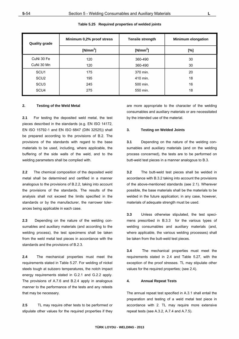
5-54 Section 5 - Welding Consumables and Auxiliary Materials L
TÜRK LOYDU - WELDING - 2013
Table 5.25 Required properties of welded joints
Quality grade Minimum 0,2% proof stress Tensile strength Minimum elongation
[N/mm2] [N/mm2] [%]
CuNi 30 Fe
CuNi 30 Mn
120
120
360-490
360-490
30
30
SCU1
SCU2
SCU3
SCU4
175
195
245
275
370 min.
410 min.
500 min.
550 min.
20
18
16
18
2. Testing of the Weld Metal
2.1 For testing the deposited weld metal, the test
pieces described in the standards (e.g. EN ISO 14172,
EN ISO 15792-1 and EN ISO 6847 (DIN 32525)) shall
be prepared according to the provisions of B.2. The
provisions of the standards with regard to the base
materials to be used, including, where applicable, the
buffering of the side walls of the weld, and to the
welding parameters shall be complied with.
2.2 The chemical composition of the deposited weld
metal shall be determined and certified in a manner
analogous to the provisions of B.2.2, taking into account
the provisions of the standards. The results of the
analysis shall not exceed the limits specified in the
standards or by the manufacturer, the narrower toler-
ances being applicable in each case.
2.3 Depending on the nature of the welding con-
sumables and auxiliary materials (and according to the
welding process), the test specimens shall be taken
from the weld metal test pieces in accordance with the
standards and the provisions of B.2.3. 2.4 The mechanical properties must meet the
requirements stated in Table 5.27. For welding of nickel
steels tough at subzero temperatures, the notch impact
energy requirements stated in G.2.1 and G.2.2 apply.
The provisions of A.7.6 and B.2.4 apply in analogous
manner to the performance of the tests and any retests
that may be necessary.
2.5 TL may require other tests to be performed or
stipulate other values for the required properties if they
are more appropriate to the character of the welding
consumables and auxiliary materials or are necessitated
by the intended use of the material.
3. Testing on Welded Joints
3.1 Depending on the nature of the welding con-
sumables and auxiliary materials (and on the welding
process concerned), the tests are to be performed on
butt-weld test pieces in a manner analogous to B.3.
3.2 The butt-weld test pieces shall be welded in
accordance with B.3.2 taking into account the provisions
of the above-mentioned standards (see 2.1). Wherever
possible, the base materials shall be the materials to be
welded in the future application; in any case, however,
materials of adequate strength must be used.
3.3 Unless otherwise stipulated, the test speci-
mens prescribed in B.3.3 for the various types of
welding consumables and auxiliary materials (and,
where applicable, the various welding processes) shall
be taken from the butt-weld test pieces.
3.4 The mechanical properties must meet the
requirements stated in 2.4 and Table 5.27, with the
exception of the proof stresses. TL may stipulate other
values for the required properties; (see 2.4).
4. Annual Repeat Tests
The annual repeat test specified in A.3.1 shall entail the
preparation and testing of a weld metal test piece in
accordance with 2. TL may require more extensive
repeat tests (see A.3.2, A.7.4 and A.7.5).

L Section 5 - Welding Consumables and Auxiliary Materials 5-55
TÜRK LOYDU - WELDING - 2013
Table 5.26 Welding consumables and auxiliary material for nickel and nickel alloys
Quality grade
Testing and approval relating to Materials also covered by the approval
Designation Material No. Designation Material No.
NİTi3
(2.4156) Ni99,6 2.4060
Ni99,2
Ni99,6
LCNi99,6
LCNi99
2.4066
2.4056
2.4061
2.4068
And joints different non-ferrous metal alloys and
with steels
NiTi4
(2.4155) Ni99,6 2.4060 As for NiTi3
NiCr19Nb
(2.4648) NiCr15Fe 2.4816
NiCr15 Fe
LC-NiCr15 Fe
NiCr20 Ti
NiCr20 TiAl
NiCr23 Fe
2.4816
2.4817
2.4951
2.4952
2.4851
And welded joints between different nickel alloys
(except for NiCu) and with steels, welded joints
in nickel steels tough at subzero temperatures
NiCr20Nb
(2.4806) NiCr15Fe 2.4816 As for NiCr19Nb
NiCr16FeMn
(2.4620) NiCr15Fe 2.4816 As for NiCr19Nb
NiCr20Mo9Nb
(2.4621) NiCr22Mo9Nb 2.4856
NiCr21Mo
NiCr22Mo6Cu
NiCr22Mo7Cu
NiCr21Mo6Cu
2.4858
2.4618
2.4619
2.4641
Nickel steels tough at subzero temperatures
NiCr21Mo9Nb
(2.4831) NiCr22Mo9Nb 2.4856 As for NiCr20Mo9Nb
NiCu30Mn
(2.4366) NiCu30Fe 2.4360 Joints with dissimilar materials, namely with
unalloyed structural steels to EN 10025-1 and
boiler steels to EN 10028-2 NiCu30MnTi
(2.4377) NiCu30Fe 2.4360

5-56 Section 5 - Welding Consumables and Auxiliary Materials L
TÜRK LOYDU - WELDING - 2013
Table 5.27 Required properties of the nickel and nickel alloys
Quality grade
Proof stresses Tensile strength Elongation
Rp0,2
[N/mm2]
min
Rp1,0
[N/mm2]
min
Rm
[N/mm2]
min
A5
[%]
min
NiTi3
NiTi4 200 220 410
25
NiCr19Nb
NiCr20Nb 360 380 600
NiCr16FeMn 360 380 600
NiCr20Mo9Nb
NiCr21Mo9Nb 420 440 700
NiCu30Mn
NiCu30MnTi 200 220 460
(1) The notch impact energy stated in 2.4 and, where applicable, G.2.1 and G.2.2.

Section 6 – Overweldable Shop Primers 6-1
TÜRK LOYDU - WELDING - 2013
SECTION 6
OVERWELDABLE SHOP PRIMERS
A. GENERAL ...................................................................................................................................................... 6- 2
B. APPROVAL TESTING OF SHOP PRIMERS .................................................................................................. 6- 2
1. Base Material
2. Filler Metal
3. Type and Dimension of Test Samples
4. Operational Procedures
5. Test Requirements
6. Re-Tests
C. CERTIFICATION ............................................................................................................................................. 6- 3
D. PERIODICAL CONTROL TESTS ................................................................................................................... 6- 4

6-2 Section 6 – Overweldable Shop Primers A,B
TÜRK LOYDU - WELDING - 2013
A. General
1. Shop primers applied to plates and sections to
be welded are to be submitted to tests to verify their
suitability for welding in respect of their tendency towards
porosity in fillet welds.
2. The requirements of this rule apply to the
procedure for approval and periodical control tests of
over weldable shop primers. The approval is intended to
be limited to the following welding processes:
- Manual metal arc welding
- Automatic gravity welding semiautomatic bare
wire or flux cored arc welding.
The acceptance of primers for use with welding
processes in addition to those above will be specially
considered in connection with the approval of the welding
procedure at the user’s works.
3. The application for the approval is to be sent to
TL by the primer Manufacturer or authorised supplier.
4. The following information and supporting
documentation, as applicable, are to be submitted:
- Manufacturer,
- Trade name,
- Components of the primer, type of diluent and
mixture ratio,
- Instructions (preparation of surfaces, method of
application, drying time, recommended dry coat
thicknesses, etc.)
- Specified resistance to marine atmosphere,
- Documentation relevant to previous tests and
approvals.
B Approval Testing of Shop Primers
Approval tests are generally intended to verify the
suitability of primers to obtain welds whose defects are
within the usual tolerance limits. Primer samples for
approval are to be taken from a sufficiently representative
quantity of primer. Sampling procedures are to be to the
Surveyor’s satisfaction. Tests may be carried out at the
Manufacturer’s workshop, at the user’s workshop or in an
adequately equipped and staffed laboratory chosen in
agreement with TL. Welding machines, welding
procedures normally employed in shipyards and certified
welders are to be used for the tests. The primer is to be
applied and measured on the test pieces in compliance
with the Manufacturer’s specification. Thickness
measurements are to be made using proper and
calibrated equipment. Thickness measurements of the
primer applied to the samples, welding and fracture tests
are to be performed in the presence of the Surveyor.
1. Base Material
Normal strength hull steels or equivalent grades are to be
used for the test specimens.
2. Filler Metal
2.1 Approved filler metals are to be used.
2.2 Basic covered electrodes are to be used for
manual metal arc welding while acid or rutile electrodes
are to be used for gravity welding. Filler metal for tests is
chosen at the discretion of TL among those usually
employed in shipbuilding.
3. Type and Dimension of Test Samples
3.1 Test samples consist of double fillet welded T-
joints formed by plates of the following dimensions:
- 300mm x 120mm x 15mm for manual welding
and semiautomatic bare wire and flux cored arc
welding with gas shielding
- 700mm x 120mm x 15mm for automatic gravity
welding.

B,C Section 6 – Overweldable Shop Primers 6-3
TÜRK LOYDU - WELDING - 2013
3.2 Number of samples required
Different commercial brands of filler metals are to beused
for the tests as follows:
a) 4 electrodes for manual welding,
b) 1 bare wire for semiautomatic welding
c) 2 cored wires for semiautomatic flux cored arc
welding
d) 2 electrodes for gravity welding, at least one of
which is to be high efficiency.
For each brand above in (a), (b) and (c), two samples are
required to be welded, one in horizontal position and one
in vertical position, using electrodes of diameter 4 mm
and wire with diameter 1,2 mm.
For each brand in d. one sample is required to be welded
in horizontal position using electrodes with diameter 5
mm.
4. Operational Procedures
The primer thickness (measure made on dry coat) of the
test samples is to be at least 30% greater than the maxi-
mum foreseen in normal use. The pieces are to be tack
welded such as to form a T with adherent contact
between the surfaces. On one side of the T sample a fillet
weld of leg size 9 mm is to be deposited. The test fillet is
to be deposited on the other side in the horizontal and
vertical position as specified in B.1.4.2 with one bead
having dimensions not exceeding 7x7 mm (Figure 6.1).
Following visual examination, two auxiliary beads are to
be welded along the edges of the test fillet so as to
provoke fracture of its throat. After having previously
removed the first fillet, the sample is to be fractured by
suitable means aiming at closing the angle of the T so as
to induce a tensile stress at the root of the weld.
5. Test Requirements
Visual examination is to be carried out consisting of
checking the external and fractured surface to determine
weld penetration and presence of wormholes,
pores and other defects. Possible defects located within
10 mm from the ends of the weld are disregarded. Lack
of penetration having total length not exceeding 1/4 of the
weld length is accepted. Wormholes and pores having
diameter not exceeding 3 mm are generally acceptable
where the total area of porosity is not higher than 5% of
the fracture section area.
Figure 6.1 Double fillet weld production test piece
6. Re-Tests
Where a maximum of two samples for each manual and
semiautomatic continuous wire welding process and a
maximum of one sample for the gravity welding process
give negative results, re-tests on two samples for each of
those which originally failed are admitted. Both the
samples of each re-test are to provide satisfactory
results. Failing this, the primer is not approved.
C. Certification
Subject to the satisfactory outcome of the required
checks and tests, TL will issue to the Manufacturer or
supplier concerned the approval certificate for the primer
authorizing its use on surfaces of rolled steel product to
be welded.
Test sections
2nd weld
1st weld

6-4 Section 6 – Overweldable Shop Primers D
TÜRK LOYDU - WELDING - 2013
D. Periodical Control Tests
The approval has three-year validity and may be renewed
subject to the satisfactory outcome of the periodical tests
below. The samples required, of the T type like those for
approval tests, are to be welded with at least the
following filler metal:
a) 2 electrodes for manual welding
b) 1 bare wire for semiautomatic welding
c) 1 cored wire for semiautomatic flux cored arc
welding
d) 1 electrode for gravity welding.
For each electrode in (a) above, two samples are
required to be welded, one in horizontal position and one
in vertical position.
For the other materials in (b), (c) and (d), one sample is
required to be welded in horizontal position. For sampling
and test procedures, materials to be employed, test
requirements and re-tests, where applicable, the
provisions relevant to initial type approval apply. Re-tests,
in duplicate, are accepted only where a maximum of one
sample for each welding process gives negative results.
Failing this, the approval of the primer is not confirmed.
Subject to the satisfactory outcome of the required check
sand tests, a new approval certificate is issued with three
year validity.

Section 7 – General Design Principles 7-1
TÜRK LOYDU - WELDING - 2013
SECTION 7
GENERAL DESIGN PRINCIPLES
A. GENERAL ...................................................................................................................................................... 7- 2
1. Scope
2. Supplementary Rules
B. INFORMATION CONTAINED IN MANUFACTURING DOCUMENTS ........................................................... 7- 2
1. Joint/Weld Shapes, Symbols
2. Information on Fabrication
3. Requirements for Welded Joints, Inspections
C. MATERIALS, WELDABILITY ........................................................................................................................ 7- 3
1. Weldability, Processing
2. Material-Related Characteristics
3. Clad Plates
4. Pairs of Materials, Corrosion
D. DESIGN DETAILS ......................................................................................................................................... 7- 3
1. Accessibility, Workmanship and Fitness for Inspection
2. Location and Configuration of Welded Joints
3. Local Clustering of Welds, Minimum Spacing
4. Cut-Outs, Welding Apertures
5. Local Reinforcements, Plate Doubling
6. Stress Flow, Transitions
7. Double-T (cruciform) Joints, Stress in the Thickness Direction
8. Welding of Cold-Formed Sections
9. Other Design Measures
E. DIMENSIONING OF WELDED JOINTS.................................................................................................. 7- 5
1. Dimensioning, Design Calculations
2. Minimum Thicknesses of Fillet Welds
3. Machining Allowance

7-2 Section 7 – General Design Principles A,B
TÜRK LOYDU - WELDING - 2013
A. General
1. Scope
These Rules contain universal principles applicable to
the designing and dimensioning of welded joints, and to
the information contained in the manufacturing
documents.
2. Supplementary Rules
The designing and dimensioning of welded joints in the
various ranges of application is additionally governed by
the component-specific requirements stated in the
Section 12 to 16 and in the respective Rules for
Construction of TL.
B. Information Contained in Manufacturing
Documents
1. Joint / Weld Shapes, Symbols
1.1 The depiction of welded joints and also the
shapes of joints and welds shall conform to the
standards (e.g. EN ISO 17659, EN 22553/ISO 2553,
ISO 9692-1or TS). They shall be identified in the
manufacturing documents (drawings, etc.) in an
unambiguous manner, e.g. by means of the standard
symbols.
1.2 Non-standard weld shapes or symbols shall be
illustrated and, where applicable, explained in detail in
the manufacturing documents (drawings, welding
schedules or specifications). They must be approved by
TL (e.g. in conjunction with the inspection of drawings
or a welding procedure test).
1.3 A weld shape appropriate to, and adequately
dimensioned or well designed for the nature (static or
dynamic) and magnitude of the forces to be transmitted
shall be chosen. Where necessary, documentary proof
of the design calculations shall be submitted (see the
supplementary rules mentioned in A.2.).
2. Information on Fabrication
2.1 The manufacturing documents to be submitted
for approval shall contain information on fabrication
insofar as is relevant to the quality of the welded joints
and necessary for inspection by TL. Besides the
materials and weld shapes, this comprises the following
information:
- Method of weld preparation (mechanical, ther-
mal, etc.),
- Welding process, welding positions,
- Welding consumables and auxiliary materials,
- Preheating and, where applicable, heat input
during welding,
- Weld build-up and number of passes,
- Welding sequence (in special cases),
- Grooving of root (method),
- Post-weld (heat) treatments, if any,
- Number and location of any production speci-
mens to be welded at the same time (where
stipulated).
With regard to the information on the requirements
applicable to the welded joints and their inspection, see
3.
2.2 If the preparation and execution of the welds
(in conjunction with approved welding procedures,
welding consumables and auxiliary materials) conform
to normal welding and shipbuilding practice as well as to
these Rules and the recognized standards, TL may
waive the requirement that they be specially illustrated
or indicated in the manufacturing documents.
3. Requirements for Welded Joints,
Inspections
3.1 The manufacturing documents (e.g. drawings,
welding or inspection schedules) to be submitted for
approval shall also indicate the quality requirements for
the welded joints. Depending on the range of ap-
plication, this may be done by means of the weld factor

B,C,D Section 7 – General Design Principles 7-3
TÜRK LOYDU - WELDING - 2013
(Section 13 and 14), or by means of the weld quality
grade (see Section 12, I., Table 12.9) or the evaluation
category according to ISO 5817 or ISO 10042 or TS EN
ISO 5817. The tests (testing methods and scope of
testing) to be used to verify the stipulated weld quality
shall also be indicated.
3.2 The requirements to be stated also include the
leak-tightness to gases and liquids or the corrosion
resistance to particular media.
3.3 With regard to the welding procedure and
production tests, see Section 4 and the application see
Section 12 to 16, with regard to non-destructive testing,
see Section 10 and the application Sections 12 to 16.
C. Materials, Weldability
1. Weldability, Processing
Only materials of proven weldability may be used for
welded structures. Any conditions linked to the approval
of the materials or to the welding procedure tests which
impose restrictions on processing and the material
manufacturer's recommendations shall be allowed for
when designing the welded joint. With regard to the
processing and use of TM steels, special TL
recommendations are to be taken into account.
2. Material-Related Characteristics
Material-related characteristics, such as the (inferior)
strength of rolled products in the thickness direction
(see D.7.2), the softening of hardened aluminium alloys
when welded, or the different degrees of thermal ex-
pansion of the various materials, shall be allowed for
when designing and dimensioning the components and
welded joints.
3. Clad Plates
Clad plates where the efficiency of the bond between
the supporting and cladding material has been proved
by materials testing (see Chapter 2, Material, Section 3.
G) may generally be treated as solid plates (up to
medium plate thicknesses with mostly fillet welds).
4. Pairs of Materials, Corrosion
Where pairs of different materials are exposed to sea-
water or other electrolytes, e.g. welded joints between
unalloyed (hull) structural steels and stainless steels,
attention shall be paid to the increased tendency to-
wards corrosion due to the differences in electro-
chemical potential. Where possible, these welded joints
should be located at points where there is less danger
of corrosion, or special corrosion protection should be
provided (e.g. coating or cathodic protection).
D. Design Details
1. Accessibility, Workmanship and Fitness for
Inspection
1.1 Welded joints shall be planned at the design
stage to ensure that they are readily accessible during
fabrication and can be executed in the optimum welding
position and welding sequence.
1.2 Welded joints and welding sequences shall be
designed to minimize residual weld stresses and avoid
excessive deformation. Welded joints should therefore
not be over-dimensioned.
1.3 Welded joints shall be designed to ensure that
the proposed weld type and quality (e.g. complete root
fusion in the case of single- and double-bevel butt
welds) can be satisfactorily achieved under the given
fabricating conditions. Failing this, provision shall be
made for welds which are easy to execute and their
(possibly inferior) load-bearing capacity shall be allowed
for when dimensioning the welds.
1.4 Severely stressed welded joints, which are
therefore normally subject to compulsory inspection,
shall be designed to facilitate application of the most
appropriate inspection technique (radiography, ultra-
sonic or surface crack inspection, possibly in combi-
nation) so that tests offering reliable results can be
carried out.

7-4 Section 7 – General Design Principles D
TÜRK LOYDU - WELDING - 2013
2. Location and Configuration of Welded
Joints
2.1 In areas of high stress concentrations resulting
from the design - and especially in cases of dynamic
loading -, welded joints should be avoided as far as
possible or designed in such a way as to provide a
generally smooth stress profile without a significant
additional notch effect originating from the welding
operation. (Chapter 1, Hull, Section 3, D.)
2.2 Intersecting butt welds in load-bearing walls of
steam boilers and pressure vessels shall be avoided.
The longitudinal seams of pipes shall be offset relative
to one another at the pipe joints by at least 50 mm.
Intersecting butt welds in hull structures are allowed; if
possible, however, the first (e.g. longitudinal) welded
joint shall be completed and cleanly finished at the ends
before the second (e.g. transverse) joint is made.
3. Local Clustering of Welds, Minimum
Spacing
3.1 The local clustering of welds and insufficient
distances between welded joints are to be avoided (see
also Section 12, G.4). Welds shall not be over-
dimensioned. The thickness of fillet welds shall not
exceed 0.7 times the thickness of the thinner of the two
parts to be joined.
3.2 Adjacent butt welds should be separated from
each other by a distance of at least 50 mm + 4 x plate
thickness. Fillet welds should be separated from each
other and from butt welds by a distance of at least 30
mm + 3 x plate thickness. The width of interchangeable
sections (strips) of plate should, however, be at least
300 mm or ten times the plate thickness, whichever is
the greater. See also Section 12, G.4.1.
4. Cut-Outs, Welding Apertures
4.1 Adequately sized cut-outs (welding apertures)
shall be provided when, for instance, stiffeners are
applied to platings before the butt joints in the plating
are welded. See also Section 12, G.5. The welding
apertures shall be rounded with a minimum radius of 25
mm or 2 x plate thickness, whichever is the greater.
4.2 In special cases, e.g. when welding compo-
nents subject to severe dynamic stresses, instead of
providing welding apertures in the area of the butt welds
it may be advisable to make a double-bevel weld
preparation on the component to be attached to the
plating, to weld up to this from both sides and to
machine out the resulting root defect in the butt weld
from the opposite side (of the plating).
5. Local Reinforcements, Plate Doubling
5.1 Where platings (including girder plates and
tube or vessel walls) are subjected locally to increased
stresses, thicker plates should be used wherever possi-
ble in preference to plate doublings. Bearing bushes,
hubs, etc. shall invariably take the form of thicker plates,
forgings or the like welded into the plating.
5.2 Where doubling plates cannot be avoided,
their thickness should not exceed twice the plating
thickness and their width should not exceed 30 times
the doubling plate thickness. With regard to welding of
doubling plates and especially the ends of such plates,
see Section 12, G.6. With regard to the design and
welding of doubling plates as cut-out reinforcements in
pressure vessels, see the Rules for Construction.
6. Stress Flow, Transitions
6.1 All welded joints on supporting members shall
be designed to provide as smooth a stress profile as
possible with no major internal or external notches, no
discontinuities in rigidity and no obstructions to
expansion.
6.2 To this end, components with different di-
mensions shall be adjusted to one another by means of
gradual transitions (e.g. by bevelling the edges of the
thicker component). Steel castings and forgings must
therefore be provided with integrally cast or forged
welding flanges. See Section 12, G.3 and the Rules for
Construction.
7. Double-T (cruciform) Joints, Stress in the
Thickness Direction
7.1 Where, in the case of double-T (cruciform)
joints, rolled products are stressed in the thickness

D,E Section 7 – General Design Principles 7-5
TÜRK LOYDU - WELDING - 2013
mm3
2t1tmina
direction due to the residual weld stresses or the ap-
plied loads, suitable measures shall be taken in the
design of the structures to prevent lamellar tearing
(stratified fractures). Such measures include the use of
suitable weld shapes with a minimum weld volume and
a welding sequence designed to reduce the shrinkage
stresses in the thickness direction.
7.2 Where there are very severe stresses in the
thickness direction (e.g. due to bulky single- or double-
bevel butt welds), materials with enhanced
characteristics in the direction at right angles to the
surface of the product are to be used (see Chapter 2,
Material, Section 3).
8. Welding of Cold-Formed Sections
Welding of cold-formed sections of (hull) structural
steels is permissible provided that the conditions stated
in Section 12, G.8. are complied with. In special cases,
post-weld heat treatment may be necessary or
documentary proof of adequate toughness after welding
may be demanded.
9. Other Design Measures
9.1 Welds should not be located in channels of
sections owing to the danger of the presence of segre-
gations and the residual stresses in these areas arising
from the rolling process.
9.2 Welded joints (fillet weld joints) in areas where
the risk of corrosion cannot be excluded shall be
continuously executed around components, cutouts,
etc. to provide a seal.
9.3 If heat treatment is carried out on components
with sealed-off hollow spaces necessitated by the de-
sign, such as occur in the case of cut-out reinforce-
ments (doublings), mounted loose flanges or suspender
rings, a means of venting, e.g. a drilled hole, shall be
provided.
E. Dimensioning of Welded Joints
1. Dimensioning, Design Calculations
1.1 Dimensioning shall be carried out in accor-
dance with the Rules for Construction with reference to
the shape and quality of the weld in question and the
type (static or dynamic) and level of stress. The di-
mensions of the weld (if required) must be apparent
from the manufacturing documents to be submitted for
approval. In the case of fillet welds, an indication shall
also be given as to whether the dimensional data refer
to the throat thickness of the weld "a" or to the leg
length "z".
1.2 Where required by TL (e.g. in the Rules for
Construction or as part of the examination of the
drawings), mathematical proof (a general stress
analysis and/or proof of fatigue strength) shall be
furnished that the weld is adequately dimensioned.
2. Minimum Thicknesses of Fillet Welds
Fillet weld throat thicknesses shall conform to TL Rules
or the results of design calculations. Throat thicknesses
not established according to the Rules or design
calculations shall be executed, as a minimum
requirement, with a throat thickness of
a = 0,5 x plate thickness,
the smaller plate thickness being the ruling dimension.
Unless otherwise agreed (e.g. for the fully-mechanised
welding of smaller plate thicknesses in appropriate
clamping jigs), the minimum fillet weld throat thickness
shall be
but not less than 3 mm.
t1 = Smaller (e.g. the web) plate thickness in
[mm],

7-6 Section 7 – General Design Principles E
TÜRK LOYDU - WELDING - 2013
t2 = Larger (e.g. the flange) plate thickness in
[mm].
A smaller minimum fillet weld throat thickness (e.g. 2,5
mm.) may be agreed to if its faultless execution is
demonstrated by means of a welding procedure test.
3. Machining Allowance
Adequate machining allowances (thicker welds) shall be
provided for the subsequent machining of welds to
ensure that the prescribed minimum weld thicknesses
are achieved on completion of the work. This particu-
larly applies to welds with only partial penetration, as
occasionally occur for instance in machinery compo-
nents, in which case provision shall be made for ma-
chining correspondingly deeper joints from the outset. In
the case of the notch-free grinding of the welds, which is
employed in the case of particular weld quality
requirements, correspondingly thicker welds shall be
deposited.

Section 8 – Execution of Welds 8-1
TÜRK LOYDU - WELDING - 2013
SECTION 8
EXECUTION OF WELDS
A. GENERAL ......................................................................................................................................................... 8- 2
1. Scope, Supplementary Provisions
2. Welding Shop Requirements
3. Materials, Marking
4. Welding Consumables and Auxiliary Materials
5. Overweldable Shop Primers
6. Manufacturing Documents, Company Standards
B. WELD PREPARATION, ASSEMBLY ............................................................................................................... 8- 3
1. Weld Preparation
2. Weld Shapes, Root Openings (Air Gaps)
3. Alignment of Components
4. Tack Welds and Preparations for Welding
C. WEATHER PROTECTION, PREHEATING ....................................................................................................... 8- 3
D. WELDING POSITIONS, WELDING SEQUENCE ............................................................................................. 8- 4
E. PERFORMANCE OF WELDING ....................................................................................................................... 8- 4
F. STRAIGHTENING, TOLERANCES .................................................................................................................. 8- 5
G. POST-WELD-TREATMENT OF WELDS .......................................................................................................... 8- 5

8-2 Section 8 – Execution of Welds A
TÜRK LOYDU - WELDING - 2013
A. General
1. Scope, Supplementary Provisions
1.1 This section contains universal rules applicable
to the performance of welding work, extending from the
weld preparation to the completion of the welded joints
including any finishing operations. For heat treatment
see Section 9; for testing of the welded joints, Sections
10 and 11.
1.2 The performance of the welding work is ad-
ditionally governed by the application of Section 12-16.
The relevant provisions of the respective Rules for
Construction shall also be complied with.
2. Welding Shop Requirements
2.1 All workshops wishing to carry out welding
work shall comply with the welding shop requirements
stipulated in Sections 2, 3 and 4 and, where necessary,
Section 10.
2.2 Workshops shall maintain up-to-date records of
this compliance and shall submit them to the Surveyor
at his request. If necessary (e.g. in the case of a
prolonged interruption to the work, see Section 2, A.4.2
and Section 3, E.), TL may reinspect the workshop.
3. Materials, Marking
3.1 Welding may only be performed on materials
whose identity and weldability under the given fabri-
cating conditions can be unequivocally established by
reference to markings, certificates, etc.
3.2 In case of doubt, the identity and weldability of
the materials shall be verified before welding com-
mences.
4. Welding Consumables and Auxiliary
Materials
4.1 Only welding consumables and auxiliary
materials tested in accordance with Section 5,
approved by TL and of a quality grade appropriate to
the base material to be welded may be used. The
various quality grades corresponding to the different hull
structural steels shall be as shown in Table 12.1 in
Section 12.
4.2 Welding consumables and auxiliary materials
for particular materials or those intended for special
welding processes which have been approved on the
basis of a (preliminary) welding procedure test may be
used only for the range of application specified in the
relevant approval certificate. Any special conditions or
rules associated with such applications shall be com-
plied with.
4.3 Welding consumables and auxiliary materials
may only be used with the electrode diameters covered
by the tests and for the approved welding positions. The
manufacturer's instructions and recommendations for
use (e.g. the type of current and polarity used) shall be
complied with.
4.4 If necessary, welding consumables and aux-
iliary materials are to be baked, prior to use, in accor-
dance with the manufacturer's instructions (keeping to
the specified maximum baking time) and are to be kept
dry at the place of work (in heated containers or similar).
5. Overweldable Shop Primers
5.1 Overweldable shop primers which are applied
to plates, sections, etc. prior to welding and are not
removed must be tested and approved in accordance
with Section 6.
5.2 Welding shops shall ensure by suitable checks
(especially on the thickness of the coating) and
production tests carried out at random during the course
of normal fabrication that the quality of the welded joints
is not impaired to an unacceptable degree.
6. Manufacturing Documents, Company
Standards
6.1 Welds shall be executed in accordance with
approved drawings, welding schedules or company
standards recognized by TL. Exceptions to this rule are
subject to TL's consent in each individual case.
6.2 Compliance with the manufacturing documents
is the responsibility of the welding shop.

B,C Section 8 – Execution of Welds 8-3
TÜRK LOYDU - WELDING - 2013
B. Weld Preparation, Assembly
1. Weld Preparation
1.1 Weld preparation may be carried out by
thermal cutting or machining. Seam edges (groove
faces) prepared by thermal cutting shall be finished by
machining (e.g. grinding) if a detrimental effect on the
welded joint as a result of the cutting operation cannot
be ruled out. Welding edges of steel castings and
forgings shall always be ground as a minimum re-
quirement; roll scale or casting skin is to be removed.
1.2 Groove faces must be free from impurities and
defects liable to impair the quality of the welded joint,
e.g. laps, coarse grooves made by the cutting torch and
slag. Prior to welding, the welding edges shall be
inspected for defects, e.g. cracks, inclusions, blowholes
or pores, using non-destructive testing methods if
necessary.
2. Weld Shapes, Root Openings (Air Gaps)
2.1 When preparing and assembling components,
care shall be taken to ensure compliance with the weld
shapes and root openings (air gaps) specified in the
manufacturing documents. With single- and double-
bevel butt welds in particular, care shall be taken to
make an adequate root opening to achieve sufficient
root penetration.
2.2 The root opening shall not exceed twice the
specified gap. If the size of the gap permitted by this
rule is exceeded locally over a limited area, the gap may
be reduced by build-up welding of the side walls,
subject to the consent of the Surveyor. With fillet welds,
the "a" dimension shall be increased accordingly, or a
single- or double-bevel weld shall be made if the air gap
is large. Inserts and wires may not be used as fillers.
3. Alignment of Components
3.1 Components which are to be united by butt
welding are to be aligned as accurately as possible.
Sections welded to plating shall be left unwelded at the
ends for this purpose. Special attention shall be paid to
the alignment of (abutting) girders which are interrupted
by transverse members. If necessary, such alignment
shall be facilitated by drilling check holes in the
transverse member which are subsequently closed by
welding.
3.2 The permissible edge alignment error depends
on the nature, importance and loading of the component
concerned and is dealt with in the various sections of
these Rules. Where special loading conditions or other
requirements relevant to the application necessitate a
limitation of the edge alignment error, the allowable
error shall be stated in the manufacturing documents.
4. Tack Welds and Preparations for Welding
4.1 Tack welds should be used as sparingly as
possible and should be made by trained personnel.
Where their quality does not meet the requirements
applicable to the welded joint, they are to be carefully
removed before the permanent weld is made.
4.2 Clamping plates, temporary ties and aligning
pins shall be made from the same material as the base
material or from a material of similar composition and
should not be used more than necessary. Any damage
caused during their removal shall be competently
repaired.
4.3 With mechanized welding processes or when
arc striking and end crater defects in butt welds have to
be avoided, run-in and run-off plates shall be provided
in continuation of the line of the weld.
4.4 Components must be clean and dry in the area
of the welds. Any scale, rust, cutting slag, grease, paint
(except for approved overweldable shop primers),
moisture or dirt shall be carefully removed before
welding.
C. Weather Protection, Preheating
1. The areas to be welded shall be adequately
protected against climatic influences such as wind,
damp and cold and shall be preheated where neces-
sary.
2. The need for and degree of preheating is
determined by various factors, such as chemical com-
position, plate thickness, two- or three-dimensional heat
dissipation, ambient and work piece temperatures, or

8-4 Section 8 – Execution of Welds C,D,E
TÜRK LOYDU - WELDING - 2013
heat input during welding (energy applied per unit length
of weld). Details are given in Section 9, Section 12 to
16.
3. Preheating shall be applied uniformly throughout
the thickness of the plate or component over a width of
four times the plate thickness, but not less than 100
mm. Preheating may be as necessary for tack and
auxiliary welds as for fabricating welds.
D. Welding Positions, Welding Sequence
1. Welding should be performed in the optimum
welding position; positional welding is to be limited to
the indispensable minimum. The welders employed on
positional welding must be qualified for the welding
positions concerned. With regard to welding in the
vertical-down position, see Section 12, H.7.
2. The welding sequence shall be chosen to allow
shrinkage to take place as freely as possible. Butt joints
in areas of plating shall invariably be fully welded prior
to attaching girders and stiffeners. TL may require an
assembly procedure or welding sequence schedule to
be drawn up in special cases.
E. Performance of Welding
1. The welding shop shall ensure that the speci-
fied welding parameters are adhered to and that the
welding work is expertly performed.
2. Components shall not be subjected to any
appreciable movements or vibration during welding.
Parts to be assembled while suspended from cranes or
floating shall be clamped prior to tack-welding of the
joints in such a way that no relative movement of the
parts is possible. Components which have not been fully
welded and which are to be handled or turned must
have welded joints of adequate strength.
3. Cracked tack welds may not be welded over,
but are to be machined out. In multi-pass welding, the
slag of the previous run shall be completely removed
before the next pass is laid down. Pores, visible slag
inclusions and other welding defects and cracks may
not be welded over, but are to be machined out and
repaired.
4. Welds must have sufficient penetration and
must display a clean, regular surface with "gentle"
transitions to the base material. Excessive weld rein-
forcements and undercuts or notches affecting the
edges of plates and cutouts are to be avoided.
5. Butt-welded joints must display full fusion over
the entire cross-section, unless otherwise specified in a
particular case. For this purpose, the root shall normally
be grooved and capped. Following a successful welding
procedure test confirmed by TL, single-side welds, e.g.
using ceramic backings, may be regarded as equivalent
to butt welds executed from both sides. Other joints
welded on one side only, e.g. using permanent
backings, are subject to TL’s approval when scrutinizing
the relevant drawings.
6. Single- and double-bevel butt welds may be
made according to the design specification either with
grooved roots as full penetration welded joints or with a
permitted incomplete penetration at the root or defined,
unwelded root face subject to the appropriate reduction
factors (see Section 12, G.10.2.). The type of weld is to
be specified in the drawings in each case and must
have received TL’s approval when scrutinizing the
drawings.
With fillet welds, particular attention shall be paid to
good root penetration. The penetration must extend to
at least the immediate vicinity of the theoretical root
point. The ideal fillet weld section is that o an equal-
sided flat-faced weld with smooth transitions to the base
material. At the ends of web plates, at cutouts and at
welding apertures, the fillet welds shall be formed round
the web to form a seal.
7. Major cases of faulty workmanship or defects
in the material may only be repaired with the Surveyor's
agreement. Minor surface defects shall be removed by
shallow grinding. Defects which penetrate more deeply
into the material (e.g. cracks, or damage caused by the
removal of auxiliary erection equipment) shall be cleanly
machined out and where necessary repair-welded with
an adequate heat input.

E,F,G Section 8 – Execution of Welds 8-5
TÜRK LOYDU - WELDING - 2013
8. Repair (so-called production welds) on steel
castings and forgings shall only be made with the
consent of the Surveyor. If their volume is considerable,
sketches and descriptions of the repair work shall be
submitted to TL’s head office for approval, together with
details of the analysis of the base material, the welding
process and the welding consumables and auxiliary
materials. TL may require stress relief heat treatment
or, in special cases, further heat treatment of the
components after welding.
9. When working and welding higher-strength hull
structural steels, high-strength (quenched and
tempered) fine-grained structural steels, austenitic
stainless steels and aluminium alloys, attention should
be paid to the relevant information and instructions in
Section 12 to 16. For this work, TL may require an
appropriate welding specification to be submitted.
F. Straightening, Tolerances
1. Straightening operations (whether thermal or
mechanical) shall not impair the quality of the materials
and welded joints. TL may require verification of the
suitability of the straightening method (e.g. by means of
a welding procedure test). This especially applies to
high-strength (quenched and tempered) fine grain
structural steels.
2. Unless specific tolerances are stated in
Section 12 to 16 or in the manufacturing documents, the
dimensional tolerances for welded structures shall be as
specified in the standards (EN/ISO 13920, ISO 5817 or
ISO 10042 or TS EN ISO 5817). See Annexes A and B.
The degree of fineness and the evaluation category
shall be stipulated in the manufacturing documents. TL
may specify other (tighter) tolerances where this is
necessary for reasons of strength and/or operational
safety.
G. Post-Weld-Treatment of Welds
1. If it is intended to carry out post-weld-treatment
of the welds, e.g. to improve the surface finish in the
case of dynamic loading, such treatment shall not impair
the characteristics (mechanical properties) of the
welded joints. TL may demand documentary proof
thereof.
2. For post-weld heat treatment, see Section 9;
for the post-treatment of surfaces for non-destructive
testing, see Section 10, F.1.

Section 9 – Heat Treatment 9-1
TÜRK LOYDU - WELDING - 2013
SECTION 9
HEAT TREATMENT
A. SCOPE ........................................................................................................................................................... 9- 2
B. EQUIPMENT AND APPLIANCES FOR HEAT TREATMENT ....................................................................... 9- 2
1. Equipment and Appliances for Preheating
2. Fixed Heat-Treatment Equipment (Heat-Treatment Furnaces)
3. Other Heat-Treatment Equipment
C. PRINCIPLES RELATING TO HEAT TREATMENT ....................................................................................... 9- 2
D. WEATHER PROTECTION, PREHEATING, HEAT INPUT DURING WELDING ........................................... 9- 3
1. Weather Protection, Welding at Low Temperatures
2. Preheating for the Welding of Ferritic Steels
3. Monitoring Interpass Temperatures
4. Welding with Controlled Heat Input per Unit Length of Weld
5. Preheating and Heat Input During the Welding of Other Steels or Metallic Materials
E. POST-WELD HEAT TREATMENT ................................................................................................................ 9- 8

9-2 Section 9 – Heat Treatment A,B,C
TÜRK LOYDU - WELDING - 2013
A. Scope
1. These Rules apply to preheating for, and heat
input during welding and to post-weld heat treatment of
welded components where required. For preheating of
hull structural steels, see also Section 12, H.4. and H.5.
2. Requirements relating to the heat treatment of
hot or cold formed welded components (e.g. spherical
or dished ends, T-pieces and elbows) are stipulated in
TL's Chapter 2, Materials.
B. Equipment and Appliances for Heat
Treatment
1. Equipment and Appliances for Preheating
Preheating may be carried out either in heat treatment
equipment or by means of mobile heating appliances,
e.g. gas burners or electrical induction or resistance
heating appliances as applicable (resistance mats). A
condition of their use is that the prescribed preheating
and interpass temperatures must be capable of being
kept constant and monitored throughout the welding
operation.
The temperature may be monitored by means of suit-
able appliances or aids, e.g. contact thermometers,
temperature sensors or temperature-sensitive crayons.
2. Fixed Heat-Treatment Equipment (Heat-
Treatment Furnaces)
2.1 The fixed heat-treatment facilities (heat-
treatment furnaces) must be of suitable size for the
particular components and structures in question and be
fitted with an appropriate temperature control facility.
The furnaces must ensure that the particular heat
treatment temperatures stipulated can be guaranteed
and that the temperature is evenly and accurately
controlled. (DIN 17052-1, quality grade C)
2.2 An adequate number of temperature recorders
shall be provided, subject to a minimum of 2 to each
furnace. The temperature variation over the period shall
be established and recorded. The temperature control
device and the temperature and time recording
instruments used shall be checked at regular intervals
(at least once a year) and documentary proof of the
inspection results submitted to TL on request.
3. Other Heat-Treatment Equipment
The primary requirements are given in B.1., but depend
upon the particular requirements relating to the
component or structure. The type and method of the
heat treatment in question is subject to TL's consent.
If no heat treatment furnace of sufficient size is available
for the heat treatment of components, heat treatment
may be carried out in mobile facilities (transportable
furnaces) or in equipment which has been specially
designed for the purpose, subject to TL's consent. Such
equipment shall comply with the requirements stated in
2.1 and 2.2 with regard to function, temperature control
and temperature recording and shall be presented to TL
for inspection before being used. Care shall be taken to
ensure that there is adequate insulation of the compo-
nents or welds needing heat treatment. Unacceptable
temperature gradients in the component shall be
avoided.
C. Principles Relating to Heat Treatment
1. Heat treatment, temperature measurements
and recording shall be performed by competent per-
sonnel.
2. The type, temperature and duration of the heat
treatment process, in addition to the rates of heating
and cooling are determined by the material, the
thickness of the material, the production process and
the nature of the component or structure. See also the
provisions of EN 1011 Parts 1 to 4 and in the
regulations given in Section 12 to 16. The information
and recommendations provided by the manufacturer of
the materials and welding consumables shall be ob-
served.
3. Details of the pre- and post-weld heat treat-
ment of a component or structure shall be included in
the production documents submitted for inspection by
TL. Where the manufacturer's welding procedure
specifications (WPS) are used, these shall contain the
necessary information relating to preheating, heat input
during welding and post-weld heat treatment.
C,D Section 9 – Heat Treatment 9-3
TÜRK LOYDU - WELDING - 2013
4. The whole of the component is normally
subject to post-weld heat treatment. The heat treatment
of part or sections of welds or the heat treatment of
partial areas, especially pressurized components,
require TL's consent in each individual case. A
specification relating to this shall be submitted to TL for
examination.
5. Where welded joints are to be produced
between different materials, in the case of complex
welded components (e.g. LNG/LPG process pressure
vessels and gas tanks), components which have high
levels of cold forming (more than 3 %) or extensive
structural and repair welds to castings, the need for,
type and extent of any heat treatment shall be agreed
with TL.
6. Parts shall be properly prepared for heat
treatment in due order. Flange facings and sealings
must be adequately protected against scaling.
Precautions shall be taken to protect against component
distortions; components and structures shall be
positioned accordingly. Unacceptable temperature
gradients during the heat treatment process and during
heating and cooling shall be avoided.
D. Weather Protection, Preheating, Heat Input
during Welding
1. Weather Protection, Welding at Low
Temperatures
1.1 The area in which welding work is performed
is to be sheltered from wind, damp and cold, particularly
if out of doors. Where gas-shielded arc welding is
carried out, special attention is to be paid to ensuring
adequate protection against draughts. When working in
the open under unfavourable weather conditions it is
advisable to dry welding edges by heating.
1.2 At ambient temperatures below + 5 °C, ad-
ditional measures shall be taken, such as shielding of
components, extensive preliminary heating and pre-
heating, especially when welding with a relatively low
heat input (energy input per unit length of weld), e.g.
when laying down thin fillet welds or in the case of rapid
heat dissipation, e.g. when welding thick-walled
components. Wherever possible, no welding should be
performed at ambient temperatures below - 10 °C.
2. Preheating for the Welding of Ferritic Steels
2.1 The need for preheating of ferritic steels and
the preheating temperature depend on a number of
factors. Chief among these are:
- The chemical composition of the base material
(carbon equivalent) and the weld metal,
- The thickness of the work piece and the type of
weld joint (two or three dimensional heat flow),
- The welding process and the welding
parameters (energy input per unit length of
weld),
- The shrinkage and transformation stresses,
- The temperature dependence of the
mechanical properties of the weld metal and
the heat-affected zone,
- The diffusible hydrogen content of the weld
metal.
2.2 The operating temperature to be maintained
(minimum preheating temperature and maximum
interpass temperature) for (hull) structural steels may
be determined in accordance with EN 1011-2. Guide
values for the preheating temperature are contained in
Figures 9.1 and 9.2 shown below for two different
energy inputs per unit length of weld (1) and hydrogen
contents HD (2) of the weld metal, together with the
various carbon equivalents CET (3).
Note :
Table 9.1 below gives guide values for the carbon equivalents
CET (3) of some of the standard grades of steel. Basis were
the information of the steel manufacturers. In case of doubt
CET has to calculate by the actual analysis.
2.3 Table 9.2 contains guide valuekz s for preheat-
ing high temperature Mo or CrMo alloy steels (used for
steam boiler) in accordance with TL's Rules for
Materials; see EN 1011-2.

9-4 Section 9 – Heat Treatment D
TÜRK LOYDU - WELDING - 2013
2.4 Table 9.3 contains guide valuesk for preheat-
ing nickel steels tough at sub-zero temperatures in
accordance with TL's Rules for Materials. For details of
this and also particulars relating to the use of austenitic
or nickel-based welding consumables, see EN 1011-2.
2.5 Depending on the complexity of the compo-
nent, the welding process applied, the level of the
residual stresses in the component and the (low) am-
bient temperature, the preheating temperatures shall be
increased or the boundary wall thicknesses reduced as
appropriate. For the effect of the various factors on the
preheating temperature level, see Table 9.4.
2.6 If the temperature of the work piece is lower
than the minimum operating temperature calculated on
the basis of the above data, preheating is called for.
Various methods are available:
- Continuous heating prior to and during welding,
- Alternate heating and welding,
- Heating only prior to the start of welding, if the
heat input during welding is sufficient to main-
tain the minimum operating temperature.
(1) Energy input per unit length of weld:
(2) HD 5 = max. 5 ml diffusible hydrogen per 100 g of
weld metal.
HD 15 = max. 15 ml diffusible hydrogen per 100 g of
weld metal.
(3) Carbon equivalent :
The above formula for calculating the carbon equivalent CET
in accordance with EN 1011-2 can be applied to steels which
have yield strengths ranging from 300 to 1000 MPa and to
the following chemical composition: 0.05- 0.32 %C, max.
0.8% Si, 0.5-1.9% Mn, max. 0.75% Mo, max. 1.5 % Cr, max.
0.7 % Cu, max. 2.5 % Ni, max. 0.12 % Ti, max. 0.18 % V,
max. 0.005 % B, max. 0.06 %Nb.
Table 9.1 Guide values for the carbon equivalent
CET
Steel grades CET (% in weight)
Average value (1) Maximum value (1) TL-A
TL-E
TL-D36
TL-E36TM
TL-D40
TL-E40TM
0.27
0.26
0.33
0.27
0.27
0.24
0.28
0.27
0.34
0.28
0.28
0.25
S275NL
S460NL
S460ML(TM)
S690QL
S890QL
0.25
0.34
0.27
0.26
0.38
0.27
0.36
0.28
0.38
0.41
C22
34CrMo4
GS20Mn5
0.26
0.49
0.34
0.29
0.55
0.41 (1) For product thicknesses up to 50 mm.
The heating method may be chosen at will, provided
that it does not harm the material by localized over-
heating or cause a nuisance by making the welding
area contaminated.
2.7 Preheating is always necessary for tack and
auxiliary welds whenever preheating is needed for the
rest of the welding. Possible exceptions to this rule are
tack and auxiliary welds where it can be guaranteed that
subsequent welds are remelted the heat affected zone,
for instance tacks for submerged arc welds.
2.8 Irrespective of the information given above,
preheating is always necessary when making major
auxiliary erection welds, e.g. when welding on handling
lugs and when welding very large wall thicknesses and
also thick-walled castings and forgings.
2.9 Preheating shall be applied uniformly
throughout the thickness of the plate or component over
a distance of four times the plate thickness, minimum of
100 mm, on both sides of the weld. Localized
overheating is to be avoided. Preheating with gas
burners should be performed with a gentle, though not
sooty, flame in order to prevent dirt being deposited in
the area of the weld. For details on the recording of the
preheating temperature, see EN IS0 13916.
mm
kJ
mmweldoflength
timeweldingAmpsIvoltsUE
100
6min
weightinNiCuCrMoMn
CCET %402010

D Section 9 – Heat Treatment 9-5
TÜRK LOYDU - WELDING - 2013
Figure 9.1 Minimum preheating temperatures (operating temperatures) applicable to welding processes with a
relatively low heat input (energy input per unit length (1) E ≈ 0.5 kJ/mm) as a function of the carbon
equivalent CET(3) of the base material and the hydrogen content of the weld metal
Figure 9.2 Minimum preheating temperatures (operating temperatures) applicable to welding processes with a
relatively high heat input (energy input per unit length (1) E ≈ 3.5 kJ/mm) as a function of the carbon
equivalent CET (3) of the base material and the hydrogen content of the weld metal
Min
imu
m p
reh
eati
ng
tem
per
atu
res
[ºC
] M
inim
um
pre
hea
tin
g t
emp
erat
ure
s [º
C]
Wall thickness [mm]
Wall thickness [mm]

9-6 Section 9 – Heat Treatment D
TÜRK LOYDU - WELDING - 2013
Table 9.2 Guide values for preheating high-temperature steels (used for steam boiler)
Category in accordance with
DIN-FACHBERICHT
CEN ISO/TR 15608
Steel grade Thickness [mm]
Minimum preheating temperature [°C] given an H2 content of the weld metal of
5 ml/100 g. > 5 - 10ml/100g > 15ml/100g
1.2 16Mo3 15
> 15 - 30 >30
20 20 75
20 75 100
100 100
Not permitted
5.1 13CrMo4-5 15 > 15
20 100
100 150
150 Not permitted
5.2 10CrMo9-10 11CrMo9-10
15 > 15
75 100
150 200
200 Not permitted
Table 9.3 Guide values for preheating nickel steels tough at sub-zero temperatures
Category in accordance with
DIN-FACHBERICHT
CEN ISO/TR 15608
Steel grade Thickness [mm]
Minimum preheating temperature [°C] given an H2 content of the weld metal of
5 ml/100 g > 5 - 10ml /100g
7.2 12Ni14 (%3,5 Ni) >10 100 150
7.3
12Ni19 (%5 Ni) >10 100 Not permitted
X8Ni9 (%9 Ni) >10 100 Not permitted
X7Ni9 (%9 Ni) > 10 100 Not permitted
Table 9.4 Effects of the various factors on the level of preheating
Shift in the preheating temperature to lower values
Factors influencing preheating
Shift in the preheating temperature to higher values
Low alloying element content Chemical composition of the base material (hardenability), e.g. expressed by the carbon equivalent
Higher alloying element content
Thin Thickness of the work piece or component (heat dissipation, rigidity, residual stress condition)
Thick
Butt joints (2 planes), thick (multiple run) welds
Type of joint, weld shape and dimensions, heat input, heat dissipation
T-joint (3 planes) thin (single-run) welds
High Ambient or work piece temperature (heat dissipation)
Low
High Heat input (energy input per unit length of weld) during welding
Low
Low Hydrogen content of the weld metal (type and rebaking of the welding consumables and auxiliary materials)
High

D Section 9 – Heat Treatment 9-7
TÜRK LOYDU - WELDING - 2013
2.10 To prevent cold cracks in higher-strength and
high-strength (quenched and tempered) steels, thick-
walled components or components of complex design, it
is advisable to use measures which give the hydrogen
introduced into the weld metal during welding sufficient
time to escape. The following methods are well
established:
- Maintenance of a specific minimum preheating
and interpass temperature throughout the
welding operation,
- Delayed cooling after welding,
- Holding at approx. 250°C prior to cooling
(hydrogen-reducing heat treatment) or
- Heat treatment immediately after welding
(without cooling in between)
2.11 Where hull structural steels or fine-grained
structural steels have undergone thermo-mechanical
processing (TM steels), the need for and degree of
preheating shall be decided on separately on the basis
of the carbon equivalent and the results of the approval
or welding procedure tests as applicable. Drying of the
areas to be welded by heating may be sufficient.
3. Monitoring Interpass Temperatures
The guide values contained in Table 9.5 for the inter-
pass temperatures relating to the various steels shall
not be significantly exceeded.
4. Welding With Controlled Heat Input Per Unit
Length of Weld
In addition to controlling the preheating and interpass
temperature, the heat input per unit length of weld shall
be controlled during welding, especially in the case of
weldable, high-strength (quenched and tempered) fine-
grained structural steels. The heat input per unit length
of weld shall not fall below or exceed the values
indicated by the steel manufacturer or those used in the
welding procedure tests and specified in the welding
procedure specifications (WPS) by any significant
amount.
5. Preheating and Heat Input During the
Welding of Other Steels or Metallic Materials
5.1 Preheating is not normally required for
austenitic materials. Preheating may be necessary for
austenitic-ferritic materials. A maximum permitted
interpass temperature which is normally between 150°C
and 180°C shall be complied with in order to prevent hot
cracks.
Table 9.5 Guide values for the maximum interpass temperature during welding
Category in
accordance
with DIN-
FACHBERICH
T CEN ISO/TR
15608
Steel grades Maximum interpas
temperature
[°C]
1.1 Normal-strength hull structural steels and comparable structural steels 250
1.2 Higher-strength structural steels and comparable structural steels 250
1.2 High-temperature, low Mo alloy steels 250
2 Normalised or thermo-mechanically processed fine-grained steels with yield strengths of > 360 N/mm2 250
3 Quenched and tempered or precipitation-hardened (excluding stainless) steels with yield strengths of > 360 N/mm2 250
5 Steels with a max. Cr content of 10 % and a max. Mo content of 1,2 % 350
7 Nickel alloy steels with a max. Ni content of 10 % 250

9-8 Section 9 – Heat Treatment D,E
TÜRK LOYDU - WELDING - 2013
5.2 Ferritic and stainless martensitic steels shall be
adequately preheated and welded using controlled heat
input per unit length of weld. Guide values for the
preheating and interpass temperatures are prescribed in
EN 1011-3.
5.3 Preheating is not normally required for welding
aluminium alloys, but should not exceed 50°C. A
maximum permitted interpass temperature of 100°C to
120°C shall be complied with in order to prevent
undesirable phase dispersion. EN 1011-4 contains
guide values for the preheating temperature to be
applied and the interpass temperature.
E. Post-Weld Heat Treatment
1. Welded components shall be subjected to
post-weld heat treatment where this is prescribed in
Sections 12 to 16. Post-weld heat treatment is generally
used for ferritic steels, in which case stress relief heat
treatment or tempering is normally sufficient. Where
consideration also has to be paid to other codes of
practice in the manufacture of certain components or
structures (e.g. TRD 201 relating to the construction of
steam boilers, see Section 13, A.2.2), the provisions
relating to post-weld heat treatment contained in these
codes of practice shall also be complied with.
Note:
The need for and type of post-weld heat treatment is
determined by various factors, the most important of which
are given below:
- Material characteristics and dimensions (wall
thicknesses)
- Minimum anticipated operating temperature
(design temperature)
- Type of operating and background environment
(e.g. risk of corrosion)
- Build-up of welds to inhibit elongation and
shrinkage
- Risk of distortion during subsequent machining
2. If stress relief heat treatment after welding is
insufficient and more extensive heat treatment is
required (e.g. normalising or quenching and tempering),
the method of heat treatment shall be specially
established in accordance with the material specification
and the conditions of use and subject to agreement by
TL. This shall also apply in analogous manner to
materials and material combinations other than those
dealt with here and also to other methods of stress-
relief.
3. The stress relief heat treatment shall be carried
out by means of slow, even heating of the components
to the prescribed temperature ranges (Table 9.6
contains guide values), holding in these ranges for two
minutes per mm of wall thickness (but not less than 30
minutes), slow cooling to 400 °C in the furnace or heat
treatment appliance, and then complete cooling in still
air. For thick-walled components, the holding time need
not be more than 150 minutes.
4. If there is a risk of the components being
distorted during cooling, the heat treatment may, within
certain limits, be carried out at a lower temperature with
an increased holding time. The required temperatures
and holding times shall be agreed with TL.
5. Joints between ferritic and austenitic steels
(weld metal) must not, as a general rule, be subjected to
heat treatment due to the risk of carbon diffusion,
except where the welds are made using nickel-base
filler materials

E Section 9 – Heat Treatment 9-9
TÜRK LOYDU - WELDING - 2013
Table 9.6 Heat treatment temperatures for stress-relief heat treatment of welded joints using similar filler
metals
Category in
accordance
with DIN-
FACHBERICH
T CEN ISO/TR
15608
Steel grades
Examples of appropriate
steels in accordance with
TL’s Rules or the standards
(1)
Heat treatment
temperature
[°C]
1.1 Normal-strength hull structural steels and comparable structural steels, grade of steel forgings and castings
TL Grade A-E 550-600
1.2 Higher-strength hull structural steels and comparable structural steels, grades of steel forgings and castings
TL Grade A36-E36 530-580
1.2 High-temperature, low Mo alloy steels 16Mo3 550-620
2 Normalised or thermo-mechanically processed fine-grained steels with yield strengths > 360 N/mm2
TL Grade A39 - E39
S460 TM 530-600
3 Quenched and tempered fine-grained structural steels with yield strengths > 360 N/mm2 S690 QL 530-580
5
5.1
5.2 Steels with a max. Cr content of 10 %, max Mo content of 1,2 %
13CrMo4-5
10CrMo9-10,11CrMo9-10 630-680
670-720 7
7.1
7.2
7.3
7.3
7.3
Nickel steels with a maximum Ni content of 10 %
13MnNi6-3 (%0,5 Ni)
12Ni14 (%3,5 Ni)
12Ni19 (%5 Ni)
X8Ni9(%9Ni)
X7Ni9 (%9 Ni)
530-560
530-560
530-560
(2)
(2) (1) Steel grades not listed here are to be classed together with comparable grades.
(2) Heat treatment should be avoided.

Section 10 – Non-Destructive Testing of Welds 10-1
TÜRK LOYDU - WELDING - 2013
SECTION 10 NON-DESTRUCTIVE TESTING OF WELDS
A. GENERAL ....................................................................................................................................................... 10- 3
1. Scope
2. Standards and Other Codes of Practice
3. Requirements Applicable to the Inspection Department
B. TEST METHODS, APPLIANCES AND TEST MEDIA .................................................................................... 10- 3
1. Test Methods
2. Test Appliances and Media
C. INSPECTION PERSONNEL, SUPERVISORS ................................................................................................ 10- 4
1. Inspection Personnel (Inspectors)
2. Inspection Supervisors
D. INSPECTION SCHEDULE, INSPECTION REPORTS .................................................................................... 10- 4
1. Inspection Schedule
2. Inspection Reports
E. TIMING OF INSPECTION, WAITING TIMES .................................................................................................. 10- 5
F. PREPARATION AND PERFORMANCE OF TESTS ...................................................................................... 10- 6
1. Preparation of Areas to be Tested
2. Performance of Tests
G. EVALUATION OF TEST RESULTS ............................................................................................................... 10- 6
1. Identification of Test Findings
2. Evaluation Criteria
3. Evaluation, Rating
H. EXTENSION OF THE SCOPE OF INSPECTION ........................................................................................... 10- 8
I. REPAIRS, RE-INSPECTION ........................................................................................................................... 10- 8
1. Repairs
2. Re-inspection
J. VISUAL INSPECTION .................................................................................................................................... 10- 8
K. RADIOGRAPHIC INSPECTION ...................................................................................................................... 10- 9
1. Radiation Sources, Appliances
2. Films, Intensifying Screens
3. Radiographic Parameters
4. Film Processing, Density, Image Quality
5. Viewing Conditions, Evaluation, Inspection Report
L. ULTRASONIC INSPECTION ......................................................................................................................... 10-11
1. Test Appliances and Accessories
2. Calibration, Sensitivity Setting
3. Surface Preparation, Coupling
4. Scanning Directions, Angle of Incidence
5. Registration Level, Evaluation of Echo Indications
6. Inspection Reports

10-2 Section 10 – Non-Destructive Testing of Welds
TÜRK LOYDU - WELDING - 2013
M. MAGNETIC PARTICLE INSPECTION ............................................................................................................ 10-16
1. Test Appliances and Media
2. Magnetization Method and Field Strength
3. Preparation of Testing Surfaces, Direction and Duration of Magnetization
4. Evaluation, Inspection Reports
N. LIQUID PENETRANT INSPECTION ............................................................................................................. 10-17
1. Test Media
2. Preparation of Testing Surfaces, Performance of Inspection
3. Evaluation, Inspection Reports
A,B Section 10 – Non-Destructive Testing of Welds 10-3
TÜRK LOYDU - WELDING - 2013
A. General
1. Scope
1.1 These Rules apply to the performance of the
non-destructive tests of welded joints according to the
methods and scopes prescribed in Section 12 to 16 the
various fields of application. See also Section 1, A.1.
and A.2.
1.2 They also apply to the performance of all non-
destructive weld tests which are stipulated in other
regulations, rules or technical instructions issued by TL
and for which no specific details are given therein.
2. Standards and Other Codes of Practice
2 1. IACS Rec 17 and the standard setc. mentioned
in the following paragraphs are an integral part of these
Rules and shall also be complied with when performing
the nondestructive weld tests. Where the standards
contradict these Rules, the latter shall take precedence.
2 2. The performance of tests according to other,
comparable codes of practice requires the prior consent
of TL. For this purpose, the relevant codes of practice
shall be submitted to TL together with the other
inspection documents (See D 1.1) for examination and
approval.
3. Requirements Applicable to the Inspection
Department
The works' inspection department shall be as
independent and free from the influence of the fabri-
cation department as it is necessary to ensure that the
inspection and the evaluation of the inspection results
are carried out objectively. This applies in analogous
manner to outside inspection bodies.
B. Test Methods, Appliances and Test Media
1. Test Methods
1.1 The choice of the test method to be used in each
case is determined among other things by the component
or weld shape, the material and the defects to be
demonstrated (type and position). See Section 12 to 16.
1.2 Unless otherwise stated in the individual
application-specific of Section 12 to 16 the following
basic requirements apply:
- Up to a wall or weld thickness of approx. 30
mm, radiographic inspection is the preferred
method; for larger thicknesses, ultrasonic in-
spection is to be used as the primary test
method.
- For wall or weld thicknesses of approx. 10 mm
and above, either radiographic or ultrasonic in-
spections may be performed, in consultation
with TL.
- For radiographic inspection, X-ray sources
shall be used wherever possible. Gamma ray
sources may only be used with TL's consent
on the basis of an examination and recognition
of the test method; see K.1.
- For magnetic materials, testing for surface
cracks shall wherever possible be carried out
by magnetic particle inspection; the use of
liquid penetrant inspections for magnetic
materials requires TL's consent in each
individual case.
1.3 The test method must be capable of reliably
detecting the external and/or internal defects which may
be present. Where necessary, this shall be achieved by
using two or more test methods in combination. The
particular test method(s) to be used shall be stated in
the inspection schedule (see D.1.1).
2. Test Appliances and Media
2.1 The test appliances and media used must
conform to the state of the art and the relevant stan-
dards and must be in perfect, serviceable condition. The
Society may require an inspection of the test appliances
and/or media used.
2.2 When making use of test equipment, test
appliances, etc. owned by other, outside testing bodies,
the works shall ensure that the conditions stated in 2.1
are satisfied.

10-4 Section 10 – Non-Destructive Testing of Welds C,D
TÜRK LOYDU - WELDING - 2013
C. Inspection Personnel, Supervisors
1. Inspection Personnel (Inspectors)
1.1 The non-destructive weld tests may only be
performed by persons trained in the use of the test
method concerned and possessing adequate practical
experience. TL shall be supplied with appropriate
documentary proof of such training and experience, e.g.
conforming to ISO 9712.
1.2 Inspection of welds by ultrasonic means shall
only be performed by inspectors holding a Level 2
certificate of accredited body (or equivalent) and having
at least 2 years of proven practical testing experience
who are recognized by TL.
1.3 For such recognition, TL may require
verification of the suitability of the ultrasonic inspection
personnel and of the test appliances and the test
method under practical conditions in the works. In
exceptional cases and where necessary for a restricted
field of use, TL may, following successful verification,
also recognize inspectors who do not hold the
certificates specified in 1.2.
1.4 Application for such verification shall be made
to TL's Head Office, accompanied by the following
information and documents:
- Documentary proof of the professional training
of the inspection personnel and, where
applicable, the inspection supervisors,
- A description of the test equipment
(appliances, probes, etc.),
- A description of the test method (instrument
setting, angles and scanning directions,
instrument sensitivity, etc.),
- Method of determining the size of defects,
- Form of the inspection report.
After successful verification, recognition may be linked
to authorization of the inspector for the independent
performance of certain tests and inspections (materials,
weld shapes) under his personal responsibility. The
decision lies with TL.
Note:
The recognition and authorization of an inspector normally
covers the inspection of normal butt and corner joints (e.g.
the joints uniting deck stringers and sheer strakes) or
approximately right-angled T-joints in hull structural steels
and/or other comparable structural steels. For the
performance of further (more difficult) tests (e.g. on other
materials and/or on acute-angled tube connections and weld
shapes of comparable complexity), the authorization shall be
subject to special review and supplementation.
2. Inspection Supervisors
2.1 An appropriately qualified works inspection
supervisor shall be available for scheduling and
monitoring the performance of the non-destructive weld
tests and evaluating the results. The name of the
inspection supervisor shall be given to TL; proof of his
qualifications (in conformity with standards Level III
certificate from accredited body or for welding
supervisor to ISO 14731 standard with additional NDT
training) shall be submitted to TL.
2.2 The inspection supervisor is responsible for
ensuring that the non-destructive weld tests are com-
petently and conscientiously carried out and recorded
by suitable inspectors in accordance with these Rules,
the relevant standards and the approved inspection
schedule.
2.3 When using the services of outside inspection
bodies, the works shall ensure that the above conditions
are satisfied and shall inform TL accordingly.
D. Inspection Schedule, Inspection Reports
1. Inspection Schedule
1.1 Unless already stated in the other manufac-
turing documents (drawings, parts lists, etc.) to be
submitted for approval, an inspection schedule for the
non-destructive weld tests shall be drawn up, which
must contain the following information:

D,E Section 10 – Non-Destructive Testing of Welds 10-5
TÜRK LOYDU - WELDING - 2013
- Components and welded joints to be tested,
- Scope and method of testing, areas to be
tested, location of testing positions, see
Section 12 to 16.
- Requirements applicable to the welded joints
(for evaluation criteria, see Section 12 to 16.
- Testing standards and/or specifications, if it is
intended to use standards or specifications dif-
ferent from those mentioned in these rules.
1.2 The location of testing positions shall be
subject to agreement between the welding shop and the
TL's Surveyor, whereupon the inspection schedule shall
be submitted to TL's Head Office for approval. TL
reserves the right to make changes to this inspection
schedule even after approval has been given and
especially to change the location of the individual
testing positions or to extend the scope of testing (see
H.) if the production process and/or test results suggest
this to be necessary.
2. Inspection Reports
2.1 Reports shall be prepared on all (initial and
repeat) tests, and these shall be submitted to the
Surveyor together with the other documentation (e.g.
radiographs). The inspection reports must contain all
the necessary details according to Sections K. to N.
relating to the particular test method used, the position
at which the test was performed and the results
obtained.
Note:
Where the test results are to be recognized in place of the
prescribed welder's repeat tests in accordance with Section
3, E.3, the inspection reports shall also state the names or
identification numbers of the welders.
2.2 Repeat tests (following repairs) and their
results shall be specially identified in the inspection
reports; see I.2.2. The results and documents relating
to the initial test shall be submitted to TL's Surveyor
along with the results and documents relating to the
repeat tests and also specifically if the repair was
arranged for in-house.
2.3 Inspection reports shall be signed by the
inspector and the test supervisor. Reports and
documentation shall be kept for six years.
E. Timing of Inspection, Waiting Times
1. Non-destructive testing of welds shall as a
general rule, not to be carried out until all the welding
operations on the component concerned have been
completed. In special cases, e.g. in the case of thick-
walled components at risk of cracking, it may be ad-
visable to carry out non-destructive tests, e.g. for
surface crack examinations, as an interim measure (in
the course of the welding work).
2. Before using the test methods described in K.
to N., a visual inspection of the welded joints shall be
performed. Surface defects which restrict the ability of
the tests to produce meaningful results or which may
lead to misinterpretation of the results shall be remedied
before any further tests are performed.
3. Components which are subjected to post-weld
heat treatment (e.g. stress relief heat treatment) shall as
a general rule be inspected after heat treatment. In-
spection of the welds for welding defects before heat
treatment as well is recommended. TL may take
previous inspections into account when establishing the
final scope of inspection. Details shall be agreed with
TL on a case-by-case basis.
4. In the case of higher-strength and especially
high-strength (e.g. quenched and tempered) structural
steels where the possibility of delayed cracking (e.g.
due to the presence of hydrogen in the weld metal)
cannot be ruled out, the tests shall not be carried out
earlier than 48 hours after completion of the welding
work. TL may demand longer waiting times (e.g. 72
hours up to a maximum of 7 days) or repetition of the
tests (at least on a random sampling basis) after an
appropriate waiting time.
5. Repetition of non-destructive tests shall be
allowed for or may be demanded if the components or
welded joints have been subjected to abnormal stresses
(e.g. while in transit or during trial loading or pressure
testing) before being stressed in normal service. The

10-6 Section 10 – Non-Destructive Testing of Welds E,F,G
TÜRK LOYDU - WELDING - 2013
type and scope of these tests shall be agreed with TL
on a case-by-case basis.
F. Preparation and Performance of Tests
1. Preparation of Areas to be Tested
1.1 The areas to be tested (surfaces of welds and
of adjacent parts of the work piece) must be sufficiently
clean and smooth for the respective test method.
Irregularities in the welded joint (see E.2) remains of
auxiliary welds, welding spatter, fragments of slag, etc.
and any protective coatings or preservatives must be
removed before the tests if they are liable to prevent
them from being performed properly.
1.2 In special cases, e.g. ultrasonic testing for
transverse defects (see L.4.3), grinding of the seam and
the surface of the work piece may be necessary.
2. Performance of Tests
2.1 Non-destructive testing of welds shall be
carried out in the manner described in Sections K. to N.
The place and date of the tests shall be notified to the
Society's Surveyor in good time. The Surveyor shall be
given the opportunity to participate in or supervise the
tests if he so wishes.
2.2 The individual positions (sections) to be tested
shall be durably marked on the component or the
welded joint in such a way that the test findings (e.g.
weld defects requiring repair) can be unequivocally
localized at any time up to the completion of all tests
and, where applicable, repairs. If the dimensions are
appropriately indicated (or a similar measure is used) in
the drawings, inspection schedules and inspection
reports, marking of the component may be dispensed
with.
G. Evaluation of Test Results
1. Identification of Test Findings
In the case of radiographic testing and, where
applicable, the methods of surface testing, the refer-
ence numbers and/or symbols conforming to ISO 6520-
1 or, as applicable, in Table 10.1 (extract from the
standard) may be used to identify (describe) test
findings (e.g. welding defects). With regard to the
description of defects in ultrasonic testing, see L.5.
2. Evaluation Criteria
2.1 Unless otherwise specified for the respective
components or welded joints in Section 12 to 16 the
evaluation categories according to ISO 5817 (Annex A)
may be used as evaluation criteria for steel and those
according to ISO 10042 (Annex B) for aluminium alloys.
2.2 In the inspection schedules, testing instruc-
tions, etc. to be drawn up by the welding shop (see
D.1.), the evaluation categories to be determined
according to the type and level of stress or, where
necessary, other individual evaluation characteristics
shall be assigned to the individual components and
welded joints. With regard to the evaluation of results of
ultrasonic testing in conjunction with the stipulations in
the above-mentioned standards (evaluation categories),
see L.5.
2.3 TL may consent to the use of different
evaluation criteria or criteria conforming to other
standards, etc. if they are approximately comparable to
those mentioned in 2.1 and are suited to the particular
test method used. Details shall be agreed with TL on a
case-by-case basis.
3. Evaluation, Rating
3.1 The inspection results shall be evaluated by
the testing department or body and/or the welding
supervisory staff. The ultimate evaluation and the
decision whether to leave defects in materials and
welds as they are or to repair them is reserved for TL’s
Surveyor.
3.2 The results may be rated according to Table
10.2 (in the case of radiographic inspection) or, in the
case of ultrasonic testing or if a broader statistical
evaluation is not required, by "leave as is" or "satisfied"
or, as the case may be, "to be repaired" or "not
satisfied".

G Section 10 – Non-Destructive Testing of Welds 10-7
TÜRK LOYDU - WELDING - 2013
Table 10.1 Symbols denoting defects (taken from ISO 6520-1)
Refence No. / symbol conforming
to the IIW X ray manual Description (1)
100 E Crack
101 Ea Longitudinal crack
102 Eb Transverse crack
104 Ec End crater crack
2011 Aa Pore
2015 Ab Elongated cavity (Gas pocket)
2016 Ab Worm hole
2024 K Crater pipe (End crater cavity)
301 Ba Slag inclusion
304 H Metallic inclusion
4011 - Lack of side-wall fusion
4012 - Lack of inter-run fusion
4013 D Lack of root fusion
402 D Lack of penetration (Incomplete penetration)
5011 F Undercut, continuous
5012 F Undercut, intermittent
5013 - Shrinkage groove, groove in the root (see 515)
502 - Excessive weld reinforcement (butt weld)
503 - Excessive convexity (fillet weld)
504 - Excessive root reinforcement
507 - Misalignment of edges
510 - Burn-through
511 - Incompletely filled groove
515 - Root concavity (see 5013)
517 - Poor restart
(1) For explanations and illustrations,see. ISO 6520-1.
Table 10.2 Evaluation ratings
Findings Rating Remarks
Weld free from detectable defects 1 = good -
Minor defects such as isolated pores
and small slag inclusions which do not
reduce the strength or tightness of the
welded joint
2 = serviceable -
Avoidable defects such as small rows
or clusters of pores, small slag lines,
short root defects and minor lack of fu-
sion
3 = leave as is
Repair not recommended for
components subject to normal stresses.
Short root defects and minor lack of
fusion may be left only at non-critical
points
Defects which must be avoided, e.g.
coarse slag inclusions, accumulations
of pores, generally all root defects and
lack of fusion, and small isolated
cracks
4 = to be repaired
Repair of defects required. Exceptions
only for components without particular
requirements on strength and tightness,
but not at cracks.
Extensive major defects and cracks 5 = to be replaced
Replacement of the section of weld or of
the entire welded joint required

10-8 Section 10 – Non-Destructive Testing of Welds H,I,J
TÜRK LOYDU - WELDING - 2013
H. Extension of the Scope of Inspection
1. If it is not certain that a defect to be repaired
ends within the tested section of the weld, the adjacent
sections of the weld shall also be inspected.
2. If major defects are found during inspections at
random, the scope of inspection shall be extended.
Unless otherwise agreed, for each section of weld to be
repaired two more of the same length shall be in-
spected.
3. In the case of ultrasonic testing, TL reserves
the right to carry out control tests at random on the
basis of the inspection reports compiled by the firm's
inspector or to require control tests to be performed by
a second, independent testing authority. If major
differences from the results of the initial tests performed
in the firm are found, the scope of the control tests may
be extended.
I. Repairs, Re-inspection
1. Repairs
1.1 Defects requiring repair on the basis of the
evaluation shall be carefully grooved over a sufficient
length (especially in the case of intersecting welds)
and/or re-welded. Where a number of defects needing
repair are located close together in a single section of
weld, the entire section shall be machined out and re-
welded.
1.2 Undercuts in need of repair, poor transitions to
the surrounding material or other surface defects shall,
where possible, be remedied by grinding out with
smooth transitions to the surrounding material or, if they
are too deep for this, they shall, with the Surveyor's
consent, be ground out and repair- welded.
2. Re-inspection
2.1 Repaired welds shall be re-inspected. Where
welds have been completely remade, retesting at least
equal in scope to the initial inspection shall be per-
formed at random in accordance with the Surveyor's
instructions.
2.2 Re-inspections shall be specially indicated in
the inspection reports and on the radiographs, e.g. by
means of an "R" (= repair) next to the title of the film
(see D.2.2).
J. Visual Inspection
1. The surfaces and back sides of the welds shall
undergo a complete visual inspection, with the aid of
optical (magnifying) appliances where necessary, to
check their external characteristics. The following
characteristics shall be checked:
- Completeness,
- Dimensional accuracy,
- Compliance with the specified weld shape,
- Absence from inadmissible external defects.
2. The dimensional accuracy shall be checked
with suitable measuring instruments on a random sam-
pling basis. When measuring fillet weld throat thick-
nesses, measuring gauges which measure with suffi-
cient accuracy in throats which are not an exact right
angle shall be used where necessary.
3. When checking for the correct shape of weld
and external defects, attention shall be paid to the
following:
- Weld reinforcement or top bead depression,
- Weld edge angles (transitions to surrounding
material),
- Misalignment of edges,
- Undercuts,
- Visible pores and slag inclusions
- Fused weld spatter,
- Arc strikes on the surface of the base material,

J,K Section 10 – Non-Destructive Testing of Welds 10-9
TÜRK LOYDU - WELDING - 2013
- Concave root surface and incomplete root
fusion,
- Cracks,
- Unequal side lengths (in the case of fillet
welds).
With regard to the limits of acceptability, see G.2. and
Section 12 to 16. Repairing of visible cracks is
mandatory.
K. Radiographic Inspection
1. Radiation Sources, Appliances
1.1 Wherever possible, X-ray units shall be used
as radiation sources for radiographic inspections. The
radiation energy (tube voltage) shall lie within the
energy limits specified in ISO 17636. Allowing for the
differences in thickness of the component, the radiation
energy (tube voltage) should be kept as low as possible
within the permissible working range so as to obtain a
high-contrast image.
1.2 Where justified in exceptional cases (e.g. by
lack of accessibility), gamma ray sources - preferably Ir
192 or Se 75 - may be used as radiation sources,
subject to TL's consent in each instance; see 4.4.
2. Films, Intensifying Screens
2.1 Class C5 films conforming to EN ISO 11699-1
or G III conforming to ISO 5579 may normally be used
in shipbuilding for X-raying steel. Class C3 or C4 and GI
or GII films, as applicable, are to be used for the
radiographic inspection of aluminium alloys and when
using gamma rays to inspect steel. The use of class C3
or C4 and GI or GII films, as applicable, is obligatory in
steam boiler, pressure vessel and pipeline manufacture
(pipe class I and II).
Note:
Annex C provides a summary of the classification of the most
popular X-ray films currently on the market. This summary
does not claim to be exhaustive and manufacturers of other
X-ray films are invited to make the classification of their
products by independent inspection institutes public and
make the appropriate documents available to TL so that they
can supplement the list.
2.2 Front and rear 0,02 mm lead screens shall
normally be used when radiographing steel. During
radiography, the film and the screens must be kept in
intimate contact in suitable cassettes, packs, etc. Ra-
diographs may be made of aluminium alloys up to about
65 mm thick without the use of intensifying screens.
2.3 The use of salt intensifying screens and fluo-
rometal screens is not allowed.
3. Radiographic Parameters
3.1 As a general rule, the radiographic parameters
prescribed in ISO 17636 for test category A (general
inspection procedure) shall be applied in shipbuilding
and those for test category B (higher-sensitivity
inspection procedure) shall be applied in steam boiler,
pressure vessel and pipeline manufacture (pipe class I
and II). In special cases TL may stipulate application of
test category B in shipbuilding as well. For radiographic
inspection using X-rays and a film length of 480 mm,
the distance between the film and the focal point shall
normally be 700 mm, and in any case not less than the
length of the film.
3.2 If several films are used to inspect a seam
(e.g. for circumferential radiographs), they shall overlap
at the ends in such a way that the full pattern of the
weld can be traced without interruption.
3.3 When inspecting pipes with an outside
diameter ≤ 90 mm, elliptical radiographs may be made
Depending on the diameter and wall thickness of the
pipe, two or more elliptical radiographs are to be mode
so that the full length of the weld (the entire
circumference of the pipe) is shown in the area of the
radiographs capable of evaluation.
3.4 For larger-diameter pipes, either double-wall
radiographs or, if the pipe diameter permits, central or
single-wall radiographs shall be made. Care shall be
taken to ensure that the film is capable of evaluation at
both its ends. The area capable of evaluation shall only
be the section of the weld in which the rays delimiting
the beam do not cover more than 1.1 times the weld
thickness that is radiographed with vertical irradiation.

10-10 Section 10 – Non-Destructive Testing of Welds K
TÜRK LOYDU - WELDING - 2013
The number of radiographs shall be determined ac-
cordingly.
3.5 In order to determine the image quality to EN
462-3 standard, at least one image quality indicator to
EN 462-1 (wire indicator) shall, for each radiograph, be
laid on the side of the weld away from the film and
facing the radiation source and shall be radiographed
together with the weld. Should this be impossible, the
image quality indicator may, with TL's consent and after
the preparation of comparative radiographs designed to
determine the changed index of image quality, be fixed
to the work piece on the side close to the film (i.e.
between the film and the weld). The film image must be
marked with a corresponding identification ("N") to
indicate that this arrangement was used, and
appropriate mention must be made in the inspection
report.
3.6 Each film image must be clearly and unmis-
takably identified by lead figures or letters simultane-
ously irradiated and depicted on the film. This identi-
fication must be the same as that given in the inspection
schedule and must enable any defects found to be
readily located. The marking is to be located outside the
weld area to be evaluated (the weld width plus at least
10 mm. on each side).
4. Film Processing, Density, Image Quality
4.1 The films must be processed in properly
equipped darkrooms in such a way as to avoid any
blemishes which interfere with their evaluation (e.g.
fogging, scratches, dark crescent-shaped marks due to
kinks in the film, etc.).
The instructions and recommendations issued by the
film and chemical manufacturers are to be followed.
Premature interruption of the developing process and
reduction with chemicals of over-exposed films is not
allowed.
4.2 The radiographic images must have a density
(D) of at least 2,0 over the entire area for evaluation.
The upper limit value depends on the brightness of the
film viewers available for the evaluation, but should not
exceed 2,5 to max. 3,0. Wide differences in density
within a single radiograph are to be avoided.
4.3 The image quality shall be determined with an
image quality indicator of the type prescribed in 3.5 and
in accordance with EN 462-1. For category A inspection
(see 3.1), image quality B is desirable for steel, with
image quality A as the minimum requirement. In the
case of aluminium alloys and test category B, image
quality B must be attained. The criterion in each case is
the smallest wire of the image quality indicator which is
still visible in the area to be evaluated, the density being
uniform.
4.4 The works or the inspection department/ body
must demonstrate on request by means of specimen
radiographs that the required radiographic parameters
and image quality can be attained.
5. Viewing Conditions, Evaluation, Inspection
Report
5.1 Viewers with a luminous density to EN
25580/ISO 5580 sufficient for the required film density
shall be used for the examination and evaluation of
radiographs. Stops must be fitted to enable the field of
view to be adapted to the film size for, or capable of,
evaluation. The brightness must be adjustable.
5.2 The viewing and evaluation of radiographs
shall take place in a dimly lit though not completely
darkened room. Evaluation should only be performed
after a sufficient period has been allowed for adaptation.
Bright, dazzling areas within the field of view are to be
screened. The use of magnifying glasses for the
detection of fine details may be beneficial.
5.3 The following information is to be given in the
inspection report, together with explanatory sketches
where necessary:
- Works number, component, inspection
schedule number, inspection position(s),
- Material, welding process,
- Thickness of work piece or weld, as
appropriate,
- Date and time of test (see E.3. and elsewhere),

K,L Section 10 – Non-Destructive Testing of Welds 10-11
TÜRK LOYDU - WELDING - 2013
- Radiation source and size of tube focus or
emitter,
- Tube voltage or activity at time of inspection,
- Radiographic arrangement to ISO 17636,
position of wire indicator,
- Type of film, nature and thickness of intensify-
ing screens,
- Test category, image quality index and image
quality class,
- Symbols denoting defects and assessment in
accordance with G.
The inspection report must also indicate whether the
information relates to an initial radiograph or to a follow-
up inspection after repair work has been carried out
(see D.2.1 and I.2.2).
5.4 The initial evaluation shall be carried out by the
welding supervisory staff and/or the works inspection
department. Then the films (initial and follow-up
radiographs, see D.2.1 and I.2.) shall be submitted to
TL's Surveyor for evaluation together with the
inspection reports (see G.3.1).
L. Ultrasonic Inspection
1. Test Appliances and Accessories
1.1 The test appliances, probes and other acces-
sories (calibration and reference blocks for adjusting the
sensitivity, reference scales, etc.) shall conform to the
state of the art and the relevant standards (e.g. EN
12223, EN ISO 7963/ISO 2400, EN ISO 17640 or EN
583-1 or related TS standards).
1.2 All possible echo heights within the range of
instrument sensitivity used must be capable of being
determined with the aid of an amplification control
calibrated in dB and a suitable scale marking on the
display. The interval between the switching stages shall
not exceed 2 dB. Instruments not equipped with a
calibrated amplification control may not be used.
1.3 Stepless controls must enable the ranges of
adjustment available on the instrument to follow on from
one another, as far as possible without any intervening
gap. Within each individual range the time sweep must
be continuously adjustable.
1.4 With regard to the geometrical characteristics
of the sound field, especially the incidence and squint
angles, the testing frequency and the resolution, the
probes must lie within the tolerances specified in the
standards mentioned above. The incidence and squint
angles shall not in either case deviate by more than 2°
from the nominal value or from the centre line of the
probe. The angle of incidence and the probe index (of
angle beam probes) shall be verified.
2. Calibration, Sensitivity Setting
2.1 The distance signal (time sweep) may be
calibrated in projection distances "a", shortened
projection distances "a'" or sonic distances "s" as
desired or, if necessary, depth positions "b". Unless
otherwise agreed, calibration in shortened projection
distances "a'" is preferred for weld inspections, or in
sonic distances "s" for parts of complex shape.
2.2 For calibration in accordance with 2.1 a cali-
bration block to EN 12223 or EN ISO 7963/ISO 2400
shall be used when testing (hull) structural steels.
Appropriate calibration or reference blocks shall be
used for materials having other sound velocities (e.g.
high-alloy steels and non-ferrous metals). Bore holes
used for calibration shall not be larger than 2 mm and
shall lie parallel to the testing surface. Where possible,
calibration should not be performed at edges.
2.3 Depending on the intended method of echo
height definition, the sensitivity setting shall be per-
formed using calibration reflectors of known shape,
position and size (e.g. large flat reflectors, side-drilled
holes) in accordance with the provisions of EN 583-2.
Unless otherwise agreed, the DGS method of
inspection shall be used. With the DGS method, the
sensitivity setting is to be carried out in accordance with
the instrument manufacturer's instructions using
calibration blocks to EN 12223 and EN ISO 7963/ISO
2400. Flat-bottom holes and grooves should not be
used as calibration reflectors.
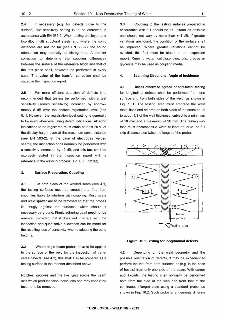
10-12 Section 10 – Non-Destructive Testing of Welds L
TÜRK LOYDU - WELDING - 2013
Testing surface
Testing area
2.4 If necessary (e.g. for defects close to the
surface), the sensitivity setting is to be corrected in
accordance with EN 583-2. When testing unalloyed and
low-alloy (hull) structural steels and where the sonic
distances are not too far (see EN 583-2), the sound
attenuation may normally be disregarded. A transfer
correction to determine the coupling differences
between the surface of the reference block and that of
the test piece shall, however, be performed in every
case. The value of the transfer correction shall be
stated in the inspection report.
2.5 For more efficient detection of defects it is
recommended that testing be performed with a test
sensitivity (search sensitivity) increased by approxi-
mately 6 dB over the chosen registration level (see
5.1). However, the registration level setting is generally
to be used when evaluating defect indications. All echo
indications to be registered must attain at least 20 % of
the display height even at the maximum sonic distance
(see EN 583-2). In the case of electrogas welded
seams, the inspection shall normally be performed with
a sensitivity increased by 12 dB, and this fact shall be
expressly stated in the inspection report with a
reference to the welding process (e.g. EG + 12 dB).
3. Surface Preparation, Coupling
3.1 On both sides of the welded seam (see 4.1)
the testing surfaces must be smooth and free from
impurities liable to interfere with coupling. Rust, scale
and weld spatter are to be removed so that the probes
lie snugly against the surfaces, which should if
necessary be ground. Firmly adhering paint need not be
removed provided that it does not interfere with the
inspection and quantitative allowance can be made for
the resulting loss of sensitivity when evaluating the echo
heights.
3.2 Where angle beam probes have to be applied
to the surface of the weld for the inspection of trans-
verse defects (see 4.3), this shall also be prepared as a
testing surface in the manner described above.
Notches, grooves and the like lying across the beam
axis which produce false indications and may impair the
test are to be removed.
3.3 Coupling to the testing surfaces prepared in
accordance with 3.1 should be as uniform as possible
and should not vary by more than ± 4 dB. If greater
variations are found, the condition of the surface shall
be improved. Where greater variations cannot be
avoided, this fact must be stated in the inspection
report. Running water, cellulose glue, oils, grease or
glycerine may be used as coupling media.
4. Scanning Directions, Angle of Incidence
4.1 Unless otherwise agreed or stipulated, testing
for longitudinal defects shall be performed from one
surface and from both sides of the weld, as shown in
Fig. 10.1. The testing area must embrace the weld
metal itself and an area on both sides of the seam equal
to about 1/3 of the wall thickness, subject to a minimum
of 10 mm and a maximum of 20 mm. The testing sur-
face must encompass a width at least equal to the full
skip distance plus twice the length of the probe.
Figure 10.1 Testing for longitudinal defects
4.2 Depending on the weld geometry and the
possible orientation of defects, it may be expedient to
perform the test from both surfaces or (e.g. in the case
of bevels) from only one side of the seam. With corner
and T-joints, the testing shall normally be performed
both from the side of the web and from that of the
continuous (flange) plate using a standard probe, as
shown in Fig. 10.2. Such probe arrangements differing

L Section 10 – Non-Destructive Testing of Welds 10-13
TÜRK LOYDU - WELDING - 2013
from 4.1 shall be specially noted in the inspection
report. The same applies in analogous manner to
curved surfaces.
Figure 10.2 Testing for longitudinal defects in
corner and T-joints
4.3 Testing for transverse defects shall be per-
formed from both sides of the weld in two directions
along the seam as shown in Fig. 10.3 or - where the
test requirements are more stringent - on the face of the
weld which has been machined flush with the surface.
TL may require that testing for transverse defects be
performed with two probes connected in parallel. Where
welds are made with a large weld pool (as in electroslag
welding), testing for oblique defects shall also be
performed at an angle of approximately 45° (see EN
ISO 17640).
4.4 With plate thicknesses (weld thicknesses) of
less than 30 mm, testing may be performed with an
angle of incidence of 70°. With thicknesses of 30 mm
and over, two angles of incidence (70° and 45° or 60°)
shall be used. Where the surface is curved, the
necessary angle of incidence shall be determined in
accordance with EN 583-2. With very large wall
thicknesses (above about 100 mm), the inspection must
be performed using a tandem technique (with fixed,
mechanical coupling of two similar probes) for different
depth zones.
Figure 10.3 Testing for transverse defects
5. Registration Level, Evaluation of Echo
Indications
Note:
Recommendations on the evaluation of the findings of
ultrasonic inspections of fusion-welded joints (in steel)
according to ISO 5817. The information sheet also contains
information on the usefulness and performance of ultrasonic
inspections and the evaluation of form-related indications.
5.1 For tests carried out by the DGS method, the
registration level (reference reflector size) for longitu-
dinal and transverse defects is given by the diameters
of the disc-shaped reflectors specified in Table 10.3 in
relation to the wall thickness (weld thickness).
Table 10.3 Registration levels
Wall thickness
(weld thickness)
Diameter of disc-shaped
reflector
4 MHz 2 MHz
From 10 - 15 mm.
Over 15 - 20 mm.
Over 20 - 40 mm.
Over 40 - 60 mm.
1,0 mm.
1,5 mm.
2,0 mm.
3,0 mm.
1,5 mm.
2,0 mm.
3,0 mm.
4,0 mm.
Where the thickness is greater than 60 mm, the regis-
tration level will be determined on a case-by-case basis.
For tandem testing, the registration level shall be
determined by a 6 mm diameter disc-shaped reflector.
For other methods of echo height definition (e.g. the
reference block method), the registration level shall be
determined in accordance with EN 583-2.

10-14 Section 10 – Non-Destructive Testing of Welds L
TÜRK LOYDU - WELDING - 2013
5.2 The registration of non-form-related echo
indications which are observed when inspecting welded
joints and whose echo heights attain or exceed the
registration level (reference reflector size) specified in
5.1 are required only when expressly stipulated by TL
or where subsequent repeat tests have to be
performed. Otherwise only those echo indications shall
be registered which exceed the repair limit value
specified in 5.4.
5.3 One characteristic which is to be stated for the
classification of echo indications is by how many dB the
maximum echo height of the reflections found differs
from the registration level defined in 5.1. In the case of
the DGS method, the size of the (substitute) disc-
shaped reflector may also be stated. Further
characteristics to be stated are the registration lengths
and half-value depths in accordance with EN ISO
17640. The location of reflections shall be defined by
coordinates indicating the "longitudinal and transverse
distances from a reference point" and the "depth
position".
5.4 Unless otherwise stated in Section 12 to 16,
echo indications produced by longitudinal defects which
exceed the repair limit values shown in Table 10.4
(excess of registration lengths and/or echo heights
above the registration level shown in Table 10.3) shall
be regarded as weld defects which must be repaired.
5.5 Continuous echo indications which point to
systematic weld defects (such as root defects due to
incomplete penetration or rows of pores) call for repairs
even if the repair limit values are not attained. Echo
indications which point to the presence of cracks
necessitate repairs in every case.
5.6 Echo indications produced by transverse
defects shall in every case count as weld defects re-
quiring repair unless they can be unequivocally associ-
ated with the indications produced by longitudinal
defects and remain below the repair limit values
stipulated in Table 10.4.
5.7 Where the evaluation of echo indications gives
rise to doubt regarding the need for repair, recourse
may be had to radiographic inspection to help in the
assessment. However, echo indications obtained with
welded seams 30 mm. or more in thickness which
exceed the repair limit values invariably necessitate
repair even if radiographic inspection fails to reveal any
defects or fails to reveal them clearly.
6. Inspection Reports
6.1 Complete inspection reports as prescribed in
EN ISO 17640 and containing the information listed
below shall be prepared for all ultrasonic inspections in
accordance with the inspection schedule; see D.1. The
inspection reports must enable the inspections to be
repeated identically. They must be signed by the person
performing the inspection and the supervisor.
6.2 Inspection reports must contain the following
general information:
- Clear identification of the component, the
material, the welded joint inspected together
with its dimensions and location (sketch to be
provided for complex weld shapes and testing
arrangements) and the welding process.
- Indication of any other rules (e.g.
specifications, standards or special
agreements) applied to the inspection.
- Place and time of the inspection, testing body
and identification of the person performing the
test.
6.3 Inspection reports must contain at least the
following specific details relating to the inspection:
- Make and type of test equipment,
- Make, type, nominal frequency and angle of
incidence of probes,
- Distance calibration (testing range),
- Sensitivity setting (calibration reflector used,
instrument sensitivity, registration level),
- Correction values (for defects close to surface,
transfer correction),
- Test sensitivity,

L Section 10 – Non-Destructive Testing of Welds 10-15
TÜRK LOYDU - WELDING - 2013
- Surface preparation, coupling media,
- Testing surfaces, testing directions, angles of
incidence.
6.4 The test results (where these are to be stated
in the inspection report; see 5.2) shall, wherever possi-
ble, be tabulated or shown on sketches with the fol-
lowing details:
- Coordinates of defects with indication of refer-
ence point,
- Maximum excess echo height (+ ... dB)
compared with the given registration level
(reference reflector size) or, where applicable,
the diameter of the corresponding (substitute)
disc-shaped reflector
- Defect characteristics (registration length, half-
value depth).
Where echo indications below the repair limit values
shown in Table 10.4 are also registered, each defect
thus identified is to be allocated an assessment (e.g.
leave as is or repair, k = acceptable or ke = not accept-
able).
Table 10.4 Repair limit values
Evaluation
category
according to
G.2.1
Wall
thickness
(weld
thickness))
[mm]
Longitudinal defects Transverse defects
Number of
defects per m
of weld seam
Registration
length
[mm]
Max.
permissible
excess echo
height
[dB]
Number of
defects per m
of weld seam
Registration
length
[mm]
Max.
permissible
excess echo
height
[dB]
B
10...15 10 and
3 and
1
10
20
10
6
6
12
3 10 6
>15...20 10 and
3 and
1
10
20
19
6
6
12
3 10 6
> 20...40 10 and
3 and
1
10
25
10
6
6
12
3 10 6
> 40 10 and
3 and
1
10
30
10
6
6
12
3 10 6
C
10...20 10 and
3 and
1
15
30
10
6
6
12
3 10 6
>20...40 10 and
3 and
1
15
30
10
6
6
12
3 10 6
> 40
10 and
3 and
1
15
50
10
6
6
12
3 10 6
D
10...20 10 and
3 and
1
15
50
10
6
6
12
5 10 6
>20...40 10 and
3 and
1
15
50
10
6
6
12
5 10 6
> 40
10 and
3 and
1
20
50
10
6
6
12
5 10 6

10-16 Section 10 – Non-Destructive Testing of Welds M
TÜRK LOYDU - WELDING - 2013
M. Magnetic Particle Inspection
1. Test Appliances and Media
1.1 The test appliances and media used must
conform to the state of the art and the relevant standards
(e.g. DIN 54130, EN ISO 9934-3, EN ISO 9934-2, EN 571-
1, EN ISO 3452-2 and EN ISO 3452-3). The magnetizing
equipment must be provided with markings or measuring
devices which indicate the magnetizing current strength at
any time. TL may stipulate that measurements be
performed to verify these data. Proof of the suitability of the
test media shall be furnished on request.
1.2 Magnetic particles suspended in suitable,
readily volatile vehicle liquids shall be used as test
media for revealing the leakage flux due to disconti-
nuities in the material. These magnetic particles may be
black or fluorescent. Where black magnetic particles are
used, the surface to be tested shall be coated with a
permanent white paint, applied as thinly as possible, to
provide a contrast.
1.3 The proportion of magnetic particles in the
vehicle liquid must conform to the manufacturer's
instructions and shall be verified (e.g. by means of a
test indicator or by a separation test using a glass cen-
trifuge vessel to ASTM D 96-73, Fig. 6). Dry test media
may only be used for tests at elevated temperatures
(e.g. on root passes).
2. Magnetization Method and Field Strength
2.1 The choice of the method of magnetization
depends on the geometry of the component and is to be
agreed with TL. If possible, magnetization shall be
effected by passing a current through the work piece or,
in the case of minor localized inspections, by yoke
magnetization using electromagnets or, if no other
possibilities are given, permanent magnets.
2.2 In special cases (e.g. where burn marks have
to be avoided at all costs or for circumferential welds), it
may be expedient to effect magnetization with a live
conductor (a cable or coil). A combination of different
methods of magnetization for the detection of variously
orientated defects is allowed.
2.3 Where a current is passed through the work-
piece, alternating, direct, impulse or surge current may
be used. AC or DC magnets may be used for yoke
magnetization. Where the magnetizing current is
passed through the workpiece, fusible supply electrodes
should be used to prevent burn marks. Where AC is
used, fusible electrodes are obligatory.
2.4 The magnetizing field strength (effective
tangential field strength) must be at least 20 A/cm (25
Oe) but shall not exceed 50 A/cm (62,5 Oe). The
adequacy of the magnetization shall be checked at the
time of the test by suitable means (e.g. test indicator) or
with a tangential field strength meter.
3. Preparation of Testing Surfaces, Direction
and Duration of Magnetization
3.1 The testing surfaces must be free from loose
scale, rust, weld spatter and other impurities. Notches,
grooves, scratches, edges, etc. which may produce
false indications are to be removed prior to inspection
Thin, dry layers of paint (e.g. shop primer, up to a coat
thickness of 20 µm) may be left in place as long as they
do not hinder the inspection.
3.2 Magnetization must be effected, as shown in
Fig. 10.4, in two different directions including an angle
of not less than 60° and not more than 90° so as to
enable variously orientated defects to be located.
Figure 10.4 Directions in which magnetization is
to be effected
3.3 Magnetization must be continued as long as
the testing surface is sprayed with magnetic particle
suspension and for as long thereafter as any movement
of the magnetic particle suspension can be detected,
subject to a minimum of 5 seconds. Testing under
conditions of remanent magnetization is not permitted.
M,N Section 10 – Non-Destructive Testing of Welds 10-17
TÜRK LOYDU - WELDING - 2013
4. Evaluation, Inspection Reports
4.1 Every accumulation of magnetic particles not
due to a false indication indicates a discontinuity or
crack in the material which is to be registered in the
inspection report and repaired. In the case of small
cracks (e.g. end crater cracks) this may be done by
grinding. Larger cracks are to be machined out and
repair-welded; see I.1.2.
4.2 Inspection reports relating to magnetic particle
inspections must include the following details:
- Details of the component and weld concerned,
- Details of magnetization, with amperage where
appropriate,
- Test arrangement (directions of magnetization,
distance between electrodes or poles),
- Test media,
- Test results
- Place and time of the inspection, testing body
and identification of the person performing the
test.
N. Liquid Penetrant Inspection
1. Test Media
1.1 Coloured or fluorescent penetrant shall be
used as penetrant media. Penetrant removers and de-
velopers must be compatible with the penetrant used.
Proof of the suitability of the inspection system
(penetrant, penetrant remover, developer) shall be
furnished to TL on request.
2. Preparation of Testing Surfaces,
Performance of Inspection
To allow the penetrant to enter any defects present, the
testing surfaces must be completely free from scale,
rust, greases, oils, paints or electrodeposits before the
penetrant is applied. During this operation care should
be taken to ensure that defects are not mechanically
sealed by preliminary cleaning. The testing surfaces
must be dry. The temperature of the work piece shall be
between 5 °C and 50 °C.
2.2 Any method of applying the penetrant may be
used. Care shall be taken to ensure that the testing
surface is completely wetted throughout the entire
penetration time. The penetration time shall be chosen
in accordance with the manufacturer's instructions, but
shall not be less than 15 minutes for work piece tem-
peratures of 15 °C and over or less than 30 minutes
where the temperature is below 15 °C. The penetrant
shall not become dry during the penetration period.
2.3 Following penetration, the surplus penetrant
shall be completely removed from the testing surface in
such a way as to leave behind the penetrant lodged in
any defects present. It is advisable first to wipe off the
surplus penetrant with a cloth and quickly to remove
only the remains with sparing use of the penetrant
remover. The testing surface should then be dried as
quickly as possible (max. 50 °C).
2.4 The developer is to be applied evenly and as
thinly as possible immediately after removal of the
surplus penetrant and drying. The testing surface
should be just covered. The developing time should be
about the same as the time allowed for penetration.
Visual inspection for defects shall begin as the devel-
oper is applied, but the final inspection can only take
place after the expiry of the developing time. M.4.1
applies in analogous manner to the evaluation.
3. Evaluation, Inspection Reports
3.1 Should an unequivocal evaluation of the
indications be impossible, the entire inspection proce-
dure, starting with preliminary cleaning, must be
repeated. Where necessary, the surface quality shall
also be improved. The repeat inspection must be
performed with the same test system as on the first
occasion. The conditions specified in standard ISO
3452-1 are also applicable.
3.2 Inspection reports relating to penetrant
medium inspections must include the following details:

10-18 Section 10 – Non-Destructive Testing of Welds N
TÜRK LOYDU - WELDING - 2013
- Details of the component and weld concerned,
- Test media (type, brand name),
- Description of the test procedure (temperature
of the work piece, penetrant acting time, etc.)
- Test results,
- Place and time of the inspection, testing body
and identification of the person performing the
test.
Inspection reports shall conform to the form provided in
Annex B to ISO 3452-1.

Section 11 – Mechanical and Technological Tests 11-1
TÜRK LOYDU - WELDING - 2013
SECTION 11
MECHANICAL AND TECHNOLOGICAL TESTS
A. SCOPE ........................................................................................................................................................... 11- 2
B. PREPARATION OF SPECIMENS AND TESTING ........................................................................................ 11- 2
C. TENSILE TESTS ............................................................................................................................................ 11- 3
1. Tensile Tests on Flat Tensile Specimens
2. Tensile Test on Round Tensile Specimens
3. Tensile Tests on Cruciform Tensile Specimens
D. BEND TESTS ................................................................................................................................................. 11- 4
1. Transverse Bend Test
2. Side Bend Test
3. Butt Weld, Longitudinal Specimens
4. Bend Test Specimens from Pipe Joints
E. NOTCHED BAR IMPACT TESTS (EN ISO 948) ........................................................................................... 11- 6
F. HARDNESS TESTING OF WELDS (EN ISO 9015) ....................................................................................... 11- 7
G. METALLOGRAPHIC INSPECTIONS ............................................................................................................ 11- 8
H. INSPECTION REPORTS ............................................................................................................................... 11- 8
I. RE-TEST PROCEDURES .............................................................................................................................. 11- 9

11-2 Section 11 – Mechanical and Technological Tests A,B
TÜRK LOYDU - WELDING - 2013
A. Scope
1. These Rules relate to the normal methods and
forms of test specimens to be used in the mechanical and
technological testing of welds, e.g. of test pieces for the
welding procedure and workmanship tests, as well as to
the metallographic inspections necessary for this purpose.
2. Special methods and forms of test specimens
(e.g. for testing the manual skill of welders or testing of
welding consumables, auxiliary materials and over
weldable shop primers) are specified in the relevant
sections.
3. The test methods and forms of specimens
indicated in the standards mentioned in the following
paragraphs shall be used wherever possible. Methods
and forms of specimens conforming to other standards
may be used by agreement with the Surveyor, provided
that the same results can be achieved.
B. Preparation of Specimens and Testing
1. All tests are to be performed by trained
personnel using calibrated testing machines. The
testing machines must be kept in good working order by
their owners and are to be calibrated at regular intervals
by an independent inspecting authority.
2. Before being cut out of the test piece, specimens
are to be marked by the Surveyor. They shall then be cut
out, wherever possible by a mechanical process, and
machined to the required dimensions. Where specimens
are cut from the test piece by a thermal process, they must
be wide enough to ensure that the heat-affected zone can
be completely machined off.
3. All mechanical and technological tests are to
be performed in the presence of the Surveyor, unless
otherwise stipulated or agreed. The photographs of
metallographic specimens are to be submitted to him for
evaluation.
4. Test specimens
4.1 Specimens dimensions
Deposited metal and butt weld tensile, butt weld bend
and Charpy V-notch impact test specimens are to be
machined to the dimensions given in UR W2 (Chapter 2
- Material, Section 2).
4.2 Specimens location and preparation
4.2.1 Deposited metal tensile
The longitudinal axis must coincide with the centre of
the weld and:
- The mid thickness of the weld in the deposited
metal test assemblies;
- The mid thickness of the 2nd run in the two-run
welded test assemblies.
The specimens may be heated to a temperature not
exceeding 250°C for a period not exceeding 16 hours
for hydrogen removal prior to testing.
4.2.2 Butt weld tensile
The upper and lower surfaces of the weld are to be
filed, ground or machined flush with the surface of the
plate.
4.2.3 Butt weld bend
The upper and lower surfaces of the weld are to be
filed, ground or machined flush with the Surface of the
plate and the sharp corners of the specimens rounded
to a radius not exceeding 2 mm.
4.2.4 Charpy V-notch impact
The test specimens shall be cut with their longitudinal
axes transverse to the weld length and:
- At mid thickness of the weld in the deposit metal
and butt weld test assemblies with multirun
technique;
- On the 2nd run side, 2 mm maximum below the
surface in the two-run welded test assemblies;
- 2 mm maximum below one surface in the
electroslag or electrogas welded test
assemblies.

B,C Section 11 – Mechanical and Technological Tests 11-3
TÜRK LOYDU - WELDING - 2013
Remainder for repeat test specimens
Ap
pro
x.40
0
The notch shall be cut in the face of the test piece
perpendicular to the surface of the plate and shall be
positioned in the centre of the weld and, for electroslag
and electrogas welded test assemblies, also at 2 mm
from the fusion line in the deposited metal.
C. Tensile Tests
1. Tensile Tests on Flat Tensile Specimens
1.1 This test is carried out to determine the tensile
strength, position, type of fracture and, where
appropriate, the elongation of specimens located at right
angles to the seam. The flat tensile specimen shown in
Fig 2.6 in Chapter 2 - Material, Section 2, B.1.2.8.2
(Refer. IACS UR W2.4.2.8 b) is to be used.
1.2 Welded joints in aluminium alloys shall be
tested using a tensile specimen conforming to ISO
4136.
2. Tensile Test on Round Tensile Specimens
2.1 Tensile tests are to be carried out on an
approved tensile testing machine. On deposited metal
test specimens, the values of yield stress, tensile
strength and elongation are to be recorded. On butt
weld specimens, the values of tensile strength are to be
recorded together with the position of fracture. Round
specimen with the dimensions stated Chapter 2 -
Material, Section 2, B.1.2.8.1 is to be used.
This test is carried out to determine the tensile strength,
yield strength or 0,2 % proof stress, reduction in area and
elongation of the weld metal. Where necessary in the
case of high-temperature steels, the 0,2 % proof stress at
elevated temperatures shall also be established.
Wherever possible, the test should be performed on a 10
mm diameter round tensile specimen. Location of
specimens is to be taken as shown in Fig. 11.1.
2.2 If, in exceptional cases, the weld dimensions
do not permit the preparation of a 10 mm diameter
tensile specimen, specimens with a smaller diameter
may be used, provided that the gauge length is 5 times
and the parallel length at least 6 times the diameter of
the specimen.
Fig. 11.1 Location of specimens in weld metal
3. Tensile Tests on Cruciform Tensile Speci-
mens
3.1 This test is carried out to determine the tensile
shear strength ZS of the weld metal. Three specimens
with the dimensions shown in Fig. 11.2 shall be tested
in each test
Fig. 11.2 Cruciform tensile specimens
3.2 The tensile shear strength Zs is to be deter-
mined by the following formula (see Fig. 11.3):
Fig. 11.3 Cruciform tensile specimen, section
through welded joint
a1 + a2 = Fracture section S1/2

11-4 Section 11 – Mechanical and Technological Tests C,D
TÜRK LOYDU - WELDING - 2013
a3 + a4 = Fracture section S3/4
Tensile shear strength ZS
SB = S 1/2 or S 3/4 depending on location fracture
D. Bend Tests
1. Transverse Bend Test
1.1 The test specimens are to be capable of
withstanding, without fracture or crack, being bent
through an angle of 120° over a former having a
diameter three times the thickness of the specimen.
However, superficial cracks of less than 3 mm long on
the outer surface should not be taken into consideration.
For each set of bend tests one specimen is to be tested
with the face of the weld in tension and the other with
the root of the weld in tension except in the electroslag
or electrogas welded test assemblies, where side bend
tests are carried out in lieu of face and root bend tests.
1.2 This test is carried out to determine the ductility
of the welded joint across the seam. For this purpose
the specimen is bent over a mandrel or prescribed
diameter and the angle achieved and, if specified, the
bending elongation on the tension side of the specimen
are measured. Specimens to Fig. 11.3a are to be
prepared for the test.
Butt welds, transverse specimen dimension:
a = t
b = 30 mm
If the as rolled thickness t is greater than 25 mm, it may
be reduced to 25 mm by machining on the compression
side of the bend specimen.
The surfaces of the weld are to be machined (ground)
flush with the surface of the plate.
1.3 Depending on the test specification, the
specimens are to be mounted in the testing device in
such a way that either the upper or the lower side of the
weld is in tension during the test. The test rig is to be set
up as shown in Fig. 11.4.
1.4 If the bending elongation is to be determined,
the deformation zone on the tension side of the
specimen shall be provided prior to the test with gauge
marks set 5 mm. apart and these shall be used to
measure the elongation when the prescribed bending
angle has been reached.
The gauge length L0 is the weld width plus the wall
thickness.
Fig. 11.3a Specimen for bend test
2N/mm
widthSpecimenBS
FloadBreaking

D Section 11 – Mechanical and Technological Tests 11-5
TÜRK LOYDU - WELDING - 2013
Tension side
Section A - B
Saw cut
Tension side
Fig. 11.4 Test rig
1.5 If the elongation behaviour of the base material
and the weld metal differ greatly, e.g. in the case of
welded aluminium test pieces, the test rig shown in Fig.
11.5 may be used in order to prevent premature
incipient cracking of the specimen.
Fig. 11.5 Special test rig
2. Side Bend Test
2.1 This test is carried out to determine the ductility
of the welded joint in the cross-sectional plane. For this
purpose the specimen is bent over a mandrel of
specified diameter and the bending angle attained is
measured. Specimens to Fig. 11.3a are to be prepared
for the test.
Side bend test specimen dimension:
a = 10 mm
b = t
If t 40 mm , the side-bend specimen may be
subdivided, each part being at least 20 mm wide
2.2 The specimens are to be mounted in the
testing device shown in Fig. 11.4 such a way that the
testing load acts in the direction of the original lon-
gitudinal axis of the seam. On the side in tension during
the test, the long edges of the specimen may be
rounded to the specified radius r.
2.3 If welded clad plates are to undergo side bend
tests, the form of specimen shown in Fig. 11.7 is to be
used. The dimensions are as stated in 2.1.
Fig. 11.6 Specimen for side bend test
Fig. 11.7 Form of clad side bend test specimens
3. Butt Weld, Longitudinal Specimens
The test specimens, for longitudinal face and root test,
are to be in accordance with an appropriate recognised
standard.
4. Bend Test Specimens from Pipe Joints
If bend test specimens are to be taken from
circumferential pipe welds, the side faces must be

11-6 Section 11 – Mechanical and Technological Tests D,E
TÜRK LOYDU - WELDING - 2013
Side in compression
parallel. If necessary, the side of the specimen which is
in compression shall be machined in accordance with
Fig. 11.8.
Fig. 11.8 Cross section through bend test
specimen taken form a pipe
E. Notched Bar Impact Tests (EN ISO 148)
1. Impact tests are to be carried out on a Charpy
impact machine of an approved type. A set of three test
specimens is to be prepared and tested. The average
absorbed energy value is to comply with the
requirements of subsequent sections. One individual
value may be less than the required average value
provided that it is not less than 70% of this value. The
test temperature for Grades 2, 2Y, 2Y 40, 3, 3Y, 3Y 40,
4Y and 4Y 40 test pieces is to be controlled to within
±2°C of the prescribed temperature.
The purpose of this test is to determine the impact
energy in joules (J). ISO V-notch specimens shall be
used; their location in the test piece shall be such that
the longitudinal axis of the specimen is perpendicular to
the direction of the seam while the notch axis is at right
angles to the surface of the product (see Fig. 11.9). In
addition, determination of the crystalline portion of the
fracture surface and/or of the lateral expansion of the
specimen may be agreed.
2. Depending on the test specification, the notch
shall be located either at the centre of the weld metal,
on the fusion line or in the heat-affected zone of the
base metal at a specified distance from the fusion line
(see Fig. 11.9).
3. The test is to be carried out at the specified
test temperature. Where the product thickness is < 10
mm, specimens measuring 7,5 x 10 mm, 5 x 10 mm.
and 2,5 x 10 mm. should be used wherever possible.
For these specimens the required impact energy E (J) in
relation to the standard 10 x 10 mm. test specimen shall
be as indicated in the Table 11.1.
4. Where specimens are taken from only one side
of a double-V weld, they shall be taken from the side of
the seam which was welded last.
Fig. 11.9 Location of specimens for notched bar impact testing

E,F Section 11 – Mechanical and Technological Tests 11-7
TÜRK LOYDU - WELDING - 2013
Table 11.1 Mean impact energy value required
Cross section of
specimen
[mm]
Mean impact energy
value required
[E]
Standard specimen
10 x 10 E
Specimens of reduced
section
10 x 7,5
10 x 5
5/6 E
2/3 E
5. The specimens shall be machined down to the
dimensions shown in Fig. 11.10 and compliance with
the stipulated tolerances shall be verified.
6. If in technically justified exceptional cases
specimens with forms or locations different from those
described in 1 to 5 are to be used, the test requirements
shall be specially agreed with TL.
Dimension Nominal
size Tolerance
Length 55 mm. ±0,60 mm.
Width 10 mm. ±0,11 mm.
Height 10 mm. ±0,06 mm.
Notch angle 45° ±2°
Height from bottom of notch 8 mm. ±0,06 mm.
Notch radius 0,25 mm. ±0,025 mm.
Distance between centre of
notch and ends of specimen 27,5 mm. ±0,42 mm.
Angle between plane of
symmetry of notch and
longitudinal axis of
specimen
90° ±2°
Angle between adjacent
longitudinal specimen
surfaces
90° ±2°
Fig. 11.10 ISO-V notch specimen
F. Hardness Testing of Welds (EN ISO 9015)
1. The hardness of welded joints shall be
measured by Vickers hardness tester using a load of 49
or 98 N (HV 5 or HV 10) on polished and etched
specimens whose test face is perpendicular to the weld
axis. The choice of the test load depends on the grade
of material concerned.
2. Normally, the test shall take the form of rows of
hardness measurements, one row for fillet welds and at
least two rows for butt welds, one of which is at the root
and one in the area of the cover pass. Should this be
insufficient for an adequate assessment of the hardness
of the welded joint, a test with a further row of
measurements shall be performed, e.g. in the area of
the root and capping passes in the case of butt welds.
The arrangement of the rows of hardness
measurements shall be as shown in Fig. 11.11.
hO = Distance from the surface
hG = Distance from the underside
hW = Distance of the row of hardness
measurements for the root area from the
surface
Fig. 11.11 Hardness testing with rows of
hardness measurements

11-8 Section 11 – Mechanical and Technological Tests F,G,H
TÜRK LOYDU - WELDING - 2013
Heat-affected zone
3. The impressions made by the hardness tester
shall be close enough together to give an accurate
picture of the hardness curve (see Fig. 11.12). The
curve shall be plotted as a graph wherever possible.
4. If other test methods are to be used in
exceptional cases, the requirements shall be converted
in accordance with recognized standards, e.g. EN ISO
18265.
G. Metallographic Inspections
1. The macro- and micro-structure shall be
evaluated by reference to polished sections. Unless
otherwise agreed, the polished face of the sections shall
be perpendicular to the weld axis (see also Fig. 11.11).
2. The metallographic specimens shall be of such
a size and ground and etched in such a way as to
reveal the nature and structure of the crystallization of
the weld metal and the heat-affected zone as well as
the texture of the base metal and, in the case of mi-
crographs, the grain boundaries in the area under
examination.
3. The polished sections shall be photographed
and the photos appended to the inspection report.
Macrographs shall normally be to a scale of 1 : 1 to
1 : 3; if the cross-sectional area of the weld is small,
they may be magnified.
For assessment of the microstructure, at least 3 pho-
tographs shall be made of characteristic parts of the
weld; these shall generally be the weld metal, the fusion
line and the heat-affected zone. The magnification shall
be at least 100 : 1.
H. Inspection reports
1. The works must prepare reports on the tests,
which must contain all the necessary details for
assessing the method. These especially include:
- Type of inspection or test (e.g. welding proce-
dure test),
- Dimensions and numbers of test pieces,
- Base materials,
- Weld preparation,
- Welding processes and positions,
- Welding consumables and their dimensions,
auxiliary welding materials,
- Welding current source,
- Welding current strength and voltage,
- Post-weld heat treatment,
- Test methods and forms of specimens,
- Test results.
2. The reports shall be submitted to the Surveyor
in at least two copies for his perusal. He shall confirm
the proper performance of the inspection and the
correctness of the results by applying his stamp and
signature.
Recommended distance between hardness test
impressions in the heat-affected zone
Fig. 11.12 Location of hardness test
impressions in the heat-affected zone
Vickers
hardness
symbol
Distance between hardness test
impressions
[mm]
HV 5 0.7
HV 10 1

I Section 11 – Mechanical and Technological Tests 11-9
TÜRK LOYDU - WELDING - 2013
I. Re-test procedures
1. Tensile and bend
Where the result of a tensile or bend test does not
comply with the requirements, duplicate test specimens
of the same type are to be prepared and satisfactorily
tested. Where insufficient original welded assembly is
available, a new assembly is to be prepared using
welding consumables from the same batch. If the new
assembly is made with the same procedure (particularly
the number of runs) as the original assembly, only the
duplicate re-test specimens needs to be prepared and
tested. Otherwise, all test specimens should be
prepared as for re-testing.
2. Charpy V-notch impact
Re-test requirements for Charpy impact tests are to be
in accordance with UR W2 (Chapter 2 – Material,
Section 2, D.1.5). Further re-tests may be made at the
Surveyor's discretion, but these must be made on a new
welded assembly and must include all tests required for
the original assembly, even those which were previously
satisfactory.

Section 12 – Welding of Hull Structures 12-1
TÜRK LOYDU - WELDING - 2013
SECTION 12
WELDING OF HULL STRUCTURES
A. GENERAL ..................................................................................................................................................... 12- 3
1. Scope
2. Other Relevant Rules and Regulations
3. Weld Performance
B. APPROVAL OF SHIPYARDS AND WELDING SHOPS, WELDING PERSONNEL ..................................... 12- 3
1. Works and Subworks
2. Requirements, Scope of Approval
3. Basic Approval, Extensions
C. QUALITY INSPECTION, RESPONSIBILITY ................................................................................................ 12- 4
D. MATERIALS, WELDABILITY ....................................................................................................................... 12- 5
E. WELDING CONSUMABLES AND AUXILIARY MATERIALS ...................................................................... 12- 5
F. WELDING PROCEDURE QUALIFICATION TESTS OF STEELS FOR HULL CONSTRUCTION AND
MARINE STRUCTURES ............................................................................................................................... 12- 8
1. Scope
2. General
3. Welding Procedure Specification
4. Qualification of Welding Procedures
5. Range of approval
6. Austenitic Stainless (Clad) and Austenitic- Ferritic (Duplex) Steels
7. Aluminium Alloys
8. Other Materials or Welding Processes
9. Scope of Application
G. DESIGN, DIMENSIONING ........................................................................................................................... 12-25
1. General
2. Characteristics Related to Materials, Corrosion
3. Stress Flow, Transitions
4. Local Clustering of Welds, Minimum Spacing, Socket Weldments
5. Welding Apertures
6. Local Reinforcements, Plate Doublings
7. Transverse Members, Stress in the Thickness Direction
8. Welding of Cold-Formed Sections, Bending Radii
9. Build-up Welds on Rudderstocks and Pintles
10. Weld Shapes and Dimensions
11. Welding at the Ends of Girders and Stiffeners
12. Joints Between Section Ends and Plates
13. Welded Shaft Bracket Joints
14. Rudder Coupling Flanges
15. Design Calculations Applied to Welded Joints

12-2 Section 12 – Welding of Hull Structures
TÜRK LOYDU - WELDING - 2013
H. EXECUTION OF WELDS ............................................................................................................................. 12-37
1. General
2. Welders and Supervisors
3. Weld Preparation and Assembly
4. Weather Protection, Welding at Low Temperatures
5. Preheating
6. Welding Positions, Vertical-Down Welding
7. Welding Sequence
8. Performance of Work
9. Welding of Higher-Strength Hull Structural Steels And High-Strength (Quenched And Tempered) Fine-
Grained Structural Steels
10. Welding of Stainless and Clad Steels
11. Welding of Steel Castings and Forgings
12. Welding of Aluminium Alloys
13. Underwater Welding
I. INSPECTION OF WELDED JOINTS ............................................................................................................. 12-44
1. General
2. Workshop Inspections, Visual Examination
3. Non-Destructive Tests
4. Production Specimens
5. Leakage Tests
6. Weld Quality Grades, Scope of Tests, Test Methods, Requirements

A,B Section 12 – Welding of Hull Structures 12-3
TÜRK LOYDU - WELDING - 2013
A. Genel
1. Scope
1.1 These rules apply to all welding work carried
out on the ship's hull, including the superstructure and
deckhouses, its internal and external structures, and
equipment components forming part of the ship's
structure, e.g. hatch covers, masts, king posts or crane
substructures welded to the ship's hull. See also
Section 1, A.1. and A.2.
1.2 IACS Rec 47 will be used as a guidance on
shipbuilding for the hull structure and repair of hull
structures of existing ships.
1.3 They also apply in analogous manner to cargo
tanks form an integral part of the ship’s hull. (Tanks and
pressure vessels stated in Section 14 which are not an
integral part of the ship's hull are excluded) e.g.
prismatic type A tanks in liqueified gas tankers.
2. Other Relevant Rules and Regulations
The design and dimensioning of welded joints is also
governed by the provisions of the Chapter 1 - Hull,
Sections 20) and the performance of the work is also
subject to the provisions of Section 1, N. of the said
Rules. For other relevant standards, see Section 1, B.
3. Weld Performance
Welded joints in hull structures shall be prepared, made
and inspected in such a way that their quality
characteristics are equivalent to those of the base ma-
terials to be joined. This means that they may not
deviate from the prescribed form and internal condition
by more than the limits allowed by the prescribed weld
quality grades according to Table 12.9 or by the
evaluation categories used as a basis for the notch
category classification for the proof of fatigue strength
(see Chapter 1 - Hull Hull, Section 3, D). The same
applies in analogous manner to the other quality
characteristics; see also C.
B. Approval of Shipyards and Welding Shops,
Welding Personnel
1. Works and Subworks
1.1 In the following items, the term "welding shop"
refers to the shipyard or welding fabrication shop which
may be considered an independent unit with regard to
its physical and organizational situation.
1.2 Branches and subcontractors are thus gener-
ally deemed to be "independent" welding shops which
have to satisfy the requirements prescribed below. In
particular, every welding shop must have a welding
supervisor who is a permanent member of the welding
shop staff (see Section 2).
1.3 Outside firms working in welding shops may
be granted approval as independent welding shops. On
this and on temporary workers, see also C.3. and
Section 1, F.
2. Requirements, Scope of Approval
2.1 All shipyards and welding shops intending to
perform welding work covered by these rules must
satisfy the requirements relating to the welding shop
and its personnel set out in Section 13 and must have
been approved for this work by TL. Applications for
approval shall be submitted by the shipyards and
welding shops in good time before starting the welding
work, enclosing the information and documentation
prescribed in Section 2, A.3.
2.2 Welding personnel (welders, operators and
supervisory staff) and where applicable inspectors and
test supervisors must meet the requirements set out in
Section 2, B.2. and B.3. and be recognized by TL. For
welder's qualification tests, see Section 3.
2.3 The scope of the approval is determined by
the capabilities of the welding shop and by the intended
range of application (materials, welding processes,
welding positions, etc.). For the period of validity of the
approval, see Section 2, A.4. and A.5.

12-4 Section 12 – Welding of Hull Structures B,C
TÜRK LOYDU - WELDING - 2013
3. Basic Approval, Extensions
3.1 For welding hull structures, as a general rule
(basic) approval is granted first of all on the basis of a
works inspection and, if necessary, welder's
qualification tests in accordance with Section 3 normally
for manual arc welding (welding process 111) and/or for
semi-mechanized metal-arc active gas welding using
solid and flux-cored wire electrodes (welding processes
135 and 136) of normal-strength hull structural steels A
to D and other comparable grades of forged and cast
steel. The thickness range is in this case determined by
the scope of the valid welder's qualification tests.
3.2 Exceptions to this rule are single-side welding
and vertical-down welding using these processes (111,
135, 136), for which welding procedure tests shall be
performed in every case. See F. One-wire submerged-
arc welding (welding process 121) may also be covered
in the basic approval described in 3.1 on the basis of
documentary proof in accordance with F.1.4 (for
conventional welding in one run on each side [two-run
technique] on plates 4 to 25 mm thick and for multipass
welding up to 40 mm).
3.3 Basic approval may be extended to include
any welding procedure approvals on the basis of
welding procedure tests as set out in Section 4 (see
also F.); in exceptional cases, however, limited approval
may also only be granted (in conjunction with a works
inspection) for a specific material and/or welding
process.
C. Quality Inspection, Responsibility
1. Shipyards and welding shops shall ensure by
means of regular in-house quality inspections during
fabrication and on completion of the welding work that
this work has been performed competently and
satisfactorily (see Section 1, F.). For the duties and
responsibilities of the welding supervisor, see also
ENISO 14731.
2. The shipyards and welding shops are respon-
sible for ensuring that the welding work conforms to
these Rules, the approved manufacturing documents,
any conditions stipulated in the approval documents,
good shipbuilding practice and the latest state of
welding practice. The inspections and checks to be
performed by TL's Surveyor do not relieve the welding
shops of this responsibility.
3. With regard to quality inspections and the
responsibilities involved in awarding subcontracts to
independent branches or suppliers or to approved or
non-approved outside firms working in the welding shop
(subcontractors), see Section 1, F. Subcontracting of
work or employment of temporary workers shall be
notified to TL.
4. The scope of the required quality inspections
depends on the construction project in question. It is
essential to ensure, however, that the intended materi-
als, welding consumables and auxiliary materials are
used and that the weld preparation, assembly,
execution of the tack and final welds and the
dimensional accuracy and completeness of the welded
joints meets the requirements stated in 2. For non-
destructive testing of the welded joints, see I.
5. Following inspection and, if necessary, repair
by the welding shop, the components shall be
presented to TL's Surveyor for checking at suitable
stages of fabrication. For this purpose they shall be
readily accessible and shall normally be uncoated.
Where the previous inspection has been inadequate,
the Surveyor may reject components and require that
they be presented again after satisfactory workshop
inspection and any necessary repair work has been
performed.
6. If the quality or good working order of a
component cannot be guaranteed or is in doubt due to
inadequate or missing information in the manufacturing
documents (e.g. production drawings), TL may demand
appropriate improvements. This applies in analogous
manner to supplementary or additional components
(e.g. reinforcements), even if these components were
not stipulated when the drawings were scrutinized or
could not be stipulated due to insufficiently detailed
representation in the class plans (see Section 1, G).

C,D,E Section 12 – Welding of Hull Structures 12-5
TÜRK LOYDU - WELDING - 2013
7. TL is not responsible for guaranteeing that all
the components and welded joints inspected to the
prescribed extent (generally on a random basis) by its
surveyors have been fabricated in accordance with the
conditions and meet the requirements in every respect.
Components or welded joints which subsequently turn
out to be defective may be rejected or their repair may
be demanded even if acceptance testing has already
been carried out.
D. Materials and Weldability
1. Welded structures may only be fabricated
using base materials of proven weldability. Materials
must comply with the Chapter 2 - Material. Other
comparable materials (e.g. structural steels conforming
to EN 10025-1) may only be used TL has given its
approval in each individual case.
2. Any conditions relating to working and welding
imposed by the approval certificate and the
recommendations of the material producer shall be
complied with. For the selection of materials for the
ship's hull, see the Chapter 1 - Hull.
3. The weldability of normal-strength hull
structural steels of quality grades A, B, D and E tested
by TL is considered proven. No measures above and
beyond the provisions of these Rules for Welding are
necessary when welding these steels.
4. The weldability of the higher-strength hull
structural steels of quality grades A 32 to F 40 approved
and tested by TL in accordance with the Rules for
Materials has been checked and can be taken for
granted if the work is carried out in accordance with
normal shipbuilding practice.
5. High-strength (quenched and tempered) fine-
grained structural steels, steels tough at subzero
temperatures, stainless structural steels and other
(alloy) structural steels have to be specially approved by
TL. The weldability of the steel in question must have
been verified in combination with welding processes
and welding consumables.
6. Steel castings and forgings shall comply with
the Rules for Materials and shall have been tested by
TL. The carbon content of components made from
carbon and carbon-manganese steels/castings for
welded structures shall not exceed 0,23 % C at ladle
analysis (check analysis: max. 0,25 % C).
7. Light metal alloys must have been tested by
TL in accordance with the Chapter 2 - Material. Their
weldability must have been verified in combination with
welding processes and welding consumables. It can
generally be taken for granted in the case of the alloys
mentioned in the Chapter 2 - Material-s.
E. Welding Consumables and Auxiliary Ma-
terials
1. All the welding consumables and auxiliary
materials used (e.g. covered electrodes, wire-gas
combinations, wire-flux combinations, etc.) must have
been approved by TL in accordance with Section 5. The
quality grade required depends on the base materials to
be welded and is shown in the relevant tables in Section
5, except for hull structural steels and other comparable
structural steels, forged steels and cast steels.
2. The correlation of the required quality grades
of welding consumables and auxiliary materials for
welding hull structural steels to the respective hull
structural steel quality grades is shown in Table 12.1.
The correlation to other comparable structural steels,
forged steels and cast steels shall be undertaken in
analogous manner.
3. For welding of different quality grades of hull
structural steel, welding consumables and auxiliary
materials shall be correlated to the steels by their quality
grades and added symbols as follows:
3.1 Normal-strength hull structural steels of
different quality grades:

12-6 Section 12 – Welding of Hull Structures E
TÜRK LOYDU - WELDING - 2013
Welding consumables and auxiliary materials for
whichever is the higher-quality (tougher) hull structural
steel, e.g. A with D: quality grade 2 ....
3.2 Higher-strength hull structural steels of the
same strength but with different quality grades:
Welding consumables and auxiliary materials for
whichever is the higher-quality, (tougher) hull structural
steel, e.g. A 36 with E 36: quality grade 3 Y....
3.3 Normal-strength with higher-strength hull struc-
tural steels with comparable quality grades:
Welding consumables and auxiliary materials for the
normal-strength hull structural steel quality grade in
question, e.g. D with D 36: quality grade 2 . (without
added symbol Y)
3.4 Normal-strength with higher-strength hull
structural steels with non-comparable quality grades:
Welding consumables and auxiliary materials having a
quality grade for the higher-quality hull structural steel
but the strength of the normal-strength steel, e.g A with
D 36:quality grade 2 (without Y symbol added)
4. For welding very thick-walled, rigid
components (approx. 30 mm and over) and welding of
forgings and steel castings, hydrogen-controlled welding
consumables and auxiliary materials of quality grade 3
H15(H) shall be used (for higher-strength hull structural
steels, 3Y H10(HH)).
5. The use of hydrogen-controlled welding con-
sumables and auxiliary materials is recommended for
welding of higher-strength hull structural steels to one
another (and to lower-strength steels) if the carbon
equivalent of these steels is over 0,41 %. See also H.5.
6. Hydrogen-controlled welding consumables and
auxiliary materials should also be used for components
which are subjected to full load immediately after
welding (e.g. lifting lugs or as a result of pressure tests)
or where allowance has to be made for a high degree of
residual stress due to the rigidity of the structure and,
where applicable, a high yield strength or strength of a
structure
7. Hydrogen-controlled welding consumables and
auxiliary materials shall always be used for welding
high-strength (quenched and tempered) finegrained
structural steels and steels tough at sub-zero
temperatures, see Section 5, F.4. For steels with a yield
strength or 0,2 % proof stress of up to 500 N/mm2,
welding consumables and auxiliary materials with the
maximum added symbol H 10 (HH) should be used and
for steels with a yield strength or 0,2 % proof stress of
over 500 N/mm2 those with a maximum added symbol
H 5 (HHH) should be used.
8. For welding of austenitic stainless steels to one
another and to hull structural steels, welding con-
sumables and auxiliary materials shall be selected in
accordance with Tables 5.21 to 5.23 in Section 5 and
the manufacturers' recommendations, taking the
corrosion resistance and strength requirements and the
welding metallurgy (including resistance to hot cracking)
into account, and specified in a welding schedule, which
is to be submitted for approval.
9. For welding aluminium alloys, the welding
consumables and auxiliary materials shall be selected
according to the type and condition of the material (see
Chapter 2 - Materials, Section 8) in accordance with
Table 5.23 in Section 5 taking the required mechanical
properties of the welded joints into account (see
Chapter 1 - Hull, Section 20) and shall be indicated in
the production documents to be submitted for approval.
10. Welding consumables and auxiliary materials
specified in a welding shop or procedure approval (see
F.) may only be replaced by equivalent consumables
approved by TL with an appropriate quality grade if this
is explicitly stated in the respective approval document.
Failing this, TL's agreement shall be obtained.
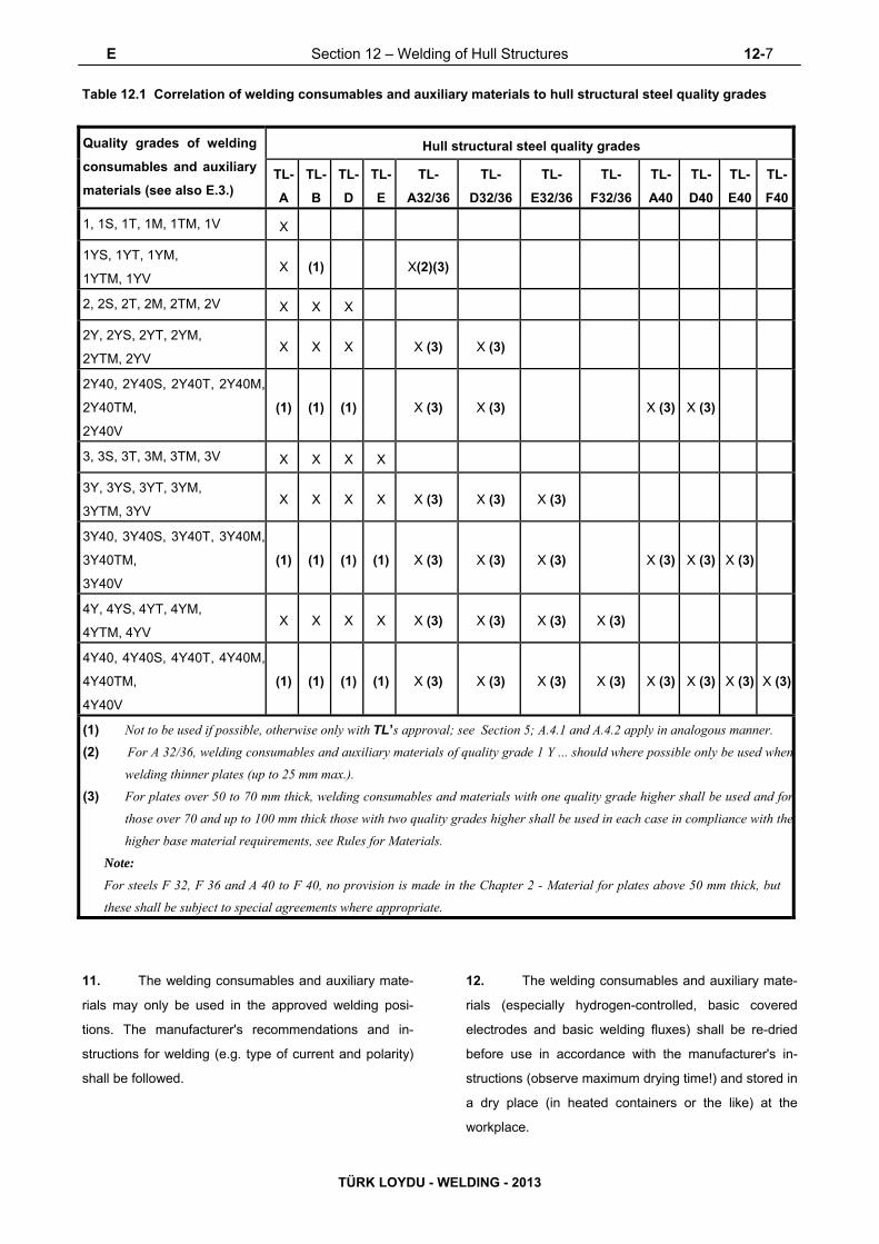
E Section 12 – Welding of Hull Structures 12-7
TÜRK LOYDU - WELDING - 2013
Table 12.1 Correlation of welding consumables and auxiliary materials to hull structural steel quality grades
Quality grades of welding
consumables and auxiliary
materials (see also E.3.)
Hull structural steel quality grades
TL-
A TL-
B TL-
D TL-
E
TL-
A32/36
TL-
D32/36
TL-
E32/36
TL-
F32/36 TL-
A40 TL-
D40 TL-
E40
TL-
F40
1, 1S, 1T, 1M, 1TM, 1V X
1YS, 1YT, 1YM,
1YTM, 1YV X (1) X(2)(3)
2, 2S, 2T, 2M, 2TM, 2V X X X
2Y, 2YS, 2YT, 2YM,
2YTM, 2YV X X X X (3) X (3)
2Y40, 2Y40S, 2Y40T, 2Y40M,
2Y40TM,
2Y40V (1) (1) (1) X (3) X (3) X (3) X (3)
3, 3S, 3T, 3M, 3TM, 3V X X X X
3Y, 3YS, 3YT, 3YM,
3YTM, 3YV X X X X X (3) X (3) X (3)
3Y40, 3Y40S, 3Y40T, 3Y40M,
3Y40TM,
3Y40V (1) (1) (1) (1) X (3) X (3) X (3) X (3) X (3) X (3)
4Y, 4YS, 4YT, 4YM,
4YTM, 4YV X X X X X (3) X (3) X (3) X (3)
4Y40, 4Y40S, 4Y40T, 4Y40M,
4Y40TM,
4Y40V (1) (1) (1) (1) X (3) X (3) X (3) X (3) X (3) X (3) X (3) X (3)
(1) Not to be used if possible, otherwise only with TL’s approval; see Section 5; A.4.1 and A.4.2 apply in analogous manner.
(2) For A 32/36, welding consumables and auxiliary materials of quality grade 1 Y ... should where possible only be used when
welding thinner plates (up to 25 mm max.).
(3) For plates over 50 to 70 mm thick, welding consumables and materials with one quality grade higher shall be used and for
those over 70 and up to 100 mm thick those with two quality grades higher shall be used in each case in compliance with the
higher base material requirements, see Rules for Materials.
Note:
For steels F 32, F 36 and A 40 to F 40, no provision is made in the Chapter 2 - Material for plates above 50 mm thick, but
these shall be subject to special agreements where appropriate.
11. The welding consumables and auxiliary mate-
rials may only be used in the approved welding posi-
tions. The manufacturer's recommendations and in-
structions for welding (e.g. type of current and polarity)
shall be followed.
12. The welding consumables and auxiliary mate-
rials (especially hydrogen-controlled, basic covered
electrodes and basic welding fluxes) shall be re-dried
before use in accordance with the manufacturer's in-
structions (observe maximum drying time!) and stored in
a dry place (in heated containers or the like) at the
workplace.

12-8 Section 12 – Welding of Hull Structures F
TÜRK LOYDU - WELDING - 2013
F. Welding Procedure Qualification Tests of
Steels for Hull Construction and Marine Structures
1. Scope
1.1 This document gives requirements for
qualification tests of welding procedures intended for
the use of weldable steels as specified in UR W7, UR
W8, UR W11 and UR W16 (Chapter 2 - Material,
Section 5, 6 and 3) for hull construction and marine
structures.
2. General
2.1 Welding procedure qualification tests are
intended to verify that a manufacturer is adequately
qualified to perform welding operations using a
particular procedure.
2.2 In general welding procedure tests are to
reflect fabrication conditions in respect to welding
equipment, inside or outside fabrication, weld
preparation, preheating and any postweld heat
treatment. It is to be the manufacturer’s responsibility to
establish and document whether a procedure is suitable
for the particular application.
2.3 For the welding procedure approval the
welding procedure qualification test is to be carried out
with satisfactory results. Welding procedure
specifications are to refer to the test results achieved
during welding procedure qualification testing.
2.4 Welding procedures qualified at a
manufacturer are valid for welding in workshops under
the same technical and quality management.
3. Welding Procedure Specification
3.1 Preliminary welding procedure
specification and welding procedure specification
3.1.1 A welding procedure specification (WPS) is to
be prepared by the shipyard or manufacturer which
intends to perform the welding procedure qualification
test. This document is also referred to as a preliminary
welding procedure specification (pWPS). The pWPS
can be modified and amended during procedure tests
as deemed necessary however it is to define all relevant
variables as mentioned in the WPS (refer to EN ISO
15614 or other recognized standards).
Where the plate thickness is less than 10 mm,
notched bar impact test specimens with a width
corresponding to the plate thickness, and wherever
possible 7.5 mm or 5 mm, may be used. In such
cases the impact energy values specified in Table
12.2 shall be reduced in accordance with Table 12.3.
3.1.2 The shipyard or manufacturer is to submit to
the TL a pWPS for review prior to the tests. In case that
the test pieces welded according to the pWPS show
unacceptable results the pWPS is to be adjusted by the
shipyard or manufacturer. The new pWPS is to be
prepared and the test pieces welded in accordance with
the new pWPS.
3.1.3 The WPS is to be used as a basis for the
production welds, and upon satisfactory completion of
the tests based on the pWPS, TL may approve it as a
WPS. In case that a WPS is approved by TL the
approval range is to be in compliance with Section 5.
4. Qualification of Welding Procedures
4.1 General
4.1.1 Preparation and welding of test pieces are to
be carried out in accordance with the pWPS and under
the general condition of production welding which it
represents.
4.1.2 Welding of the test assemblies and testing of
test specimens are to be witnessed by the Surveyor.
4.1.3 If tack welds and/or start and stop points are a
condition of the weld process they are to be fused into
the joint and are to be included in the test assemblies.
4.2 Butt weld
4.2.1 Assembly of test pieces
The test assembly is to be of a size sufficient to ensure
a reasonable heat distribution and according to Fig.
12.1 with the minimum dimensions:

F Section 12 – Welding of Hull Structures 12-9
TÜRK LOYDU - WELDING - 2013
- Manual or semi-automatic welding:
width = 2a, a = 3 x t, min 150 mm
length b = 6 x t, min 350 mm
- Automatic welding:
width = 2a, a = 4 x t, min 200 mm
length b = 1000 mm
Table 12.2 Requirements applicable to welded hull structural steel in the scope of welding procedure tests
Grade
Yield
strength
(weld
metal)
[N/mm2]
Tensile
strength
[N/mm2]
Elongation
(weld metal
L = 5 do)
[%]
Impact energy (1) (3), (4)
(J)
Bending
angle
(D = 4 t)
Bending
elongation
gauge
length
2 Ls (2)
[%]
Tempe-
rature
[°C]
Manual and semi-
mechanised Full
mechanised
PA,PC,PE PF, PG
TL-A(5)
305 400 22
+ 20
47 34 34 180 ° 22 TL-B(5),
TL-D
0
TL-E – 20
TL-A 32
335 440 22
+ 20
47 34 34 180 ° 22 TL-D 32 0
TL-E 32 – 20
TL-F 32 – 40
TL-A 36
375 490 22
+ 20
47 34 34 180 ° 22 TL-D 36 0
TL-E 36 – 20
TL-F 36 – 40
TL-A 40
400 510 22
+ 20
47 39 39 180 ° 22 TL-D 40 0
TL-E 40 – 20
TL-F 40 – 40
(1) Charpy-V-notch specimen, average value of three specimens.
(2) The gauge length (L0) = weld width (LS) + half of the plate thickness on each side adjacent to the weld; see
ISO 5173
(3) In the case of plate thickness > 50 mm, the requirements of the impact energy have to be agreed with TL prior to testing
(4) The impact requirements are valid for test pieces with weld perpendicular to the rolling direction of the plates.
(5) For grade A / B, the minimum value of impact energy is 27 J in the fusion line (FL) and in the heat affected zone (HAZ).
For hull structural steel plates impact tested in the longitudinal direction (CVN-L) in UR W11 (Chapter 2 -

12-10 Section 12 – Welding of Hull Structures F
TÜRK LOYDU - WELDING - 2013
Plate rolling direction
(Steel plates With CVN-L)
(Ste
el p
late
s
with
CV
N-L
)
Pla
te r
ollin
g di
rect
ion
Material, Section 3, B), the butt weld of the test piece is
perpendicular to the rolling direction of the two plates.
For high strength quenched and tempered steel plates
impact tested in the transverse direction (CVN-T) in UR
W16 (Chapter 2 - Material, Section 3, C), the butt weld
of the test piece is parallel to the rolling direction of the
two plates.
Table 12.3 Required impact energy values with
specimens of reduced width (see also Table 11.1)
Cross section of
specimen
[mm x mm]
Fraction of the required
minimum impact
10 x 7,5 5/6
10 x 5,0 2/3
4.2.2 Examinations and tests
Test assemblies are to be examined non-destructively
and destructively in accordance with the following and
Fig 12.2:
- Visual testing 100 %
- Surface crack detection 100 %
(dye penetrant testing or magnetic particle
testing)
- Radiographic or Ultrasonic testing 100 %
- Transverse tensile test two specimens as in
4.2.2.2
- Longitudinal tensile test required as in 4.2.2.3
- Transverse bend test four specimens as in
4.2.2.4
- Charpy V-notch impact test required as in 4.2.2.5
- Macro examination one specimen as in 4.2.2.6
- Hardness test required as in 4.2.2.7
Fig. 12.1 Test assembly for butt weld

F Section 12 – Welding of Hull Structures 12-11
TÜRK LOYDU - WELDING - 2013
Discard
or 2 side bend test
Transverse tensile test
Face bend test
Root bend test
Longitudinal tensile test
Macro examination & Hardness test
Charpy V-notch impact test (notch in weld metal)
(notch on fusion line)
(notch in HAZ)
Face bend test
Root bend testor 2 side bend test
Transverse tensile test
weld
Discard
Fig. 12.2 Test sampling
4.2.2.1 Non-destructive testing
Test assemblies are to be examined by visual and by
non-destructive testing prior to the cutting of test
specimen. In case that any post-weld heat treatment is
required or specified, non-destructive testing is to be
performed after heat treatment. For steels according to
UR W16 (Chapter 2 - Material, Section 3, C) with
specified minimum yield strength of 420 N/mm2 and
above the non-destructive testing is to be delayed for a
minimum of 48 hrs, unless heat treatment has been
carried out.
NDT procedures are to be agreed with TL.
Imperfections detected by visual or non-destructive
testing are to be assessed in accordance with ISO
5817, class B, except for excess weld metal and excess
of penetration for which the level C applies.
4.2.2.2 Transverse tensile test
The testing is to be carried out in accordance with UR
W2.4 (Chapter 2 - Material, Section 2, B.1), The tensile

12-12 Section 12 – Welding of Hull Structures F
TÜRK LOYDU - WELDING - 2013
strength recorded for each specimen is not to be less
than the minimum required for the base metal.
When butt welds are made between plates of different
grades, the tensile strength to be obtained on the welded
assembly is to be in accordance with the requirements
relating to the steel grade having lower strength.
4.2.2.3 Longitudinal tensile test
Longitudinal tensile test of deposited weld metal taken
lengthways from the weld is required for cases where
the welding consumable is not approved by TL.
The testing is to be carried out in accordance with UR
W2.4 (Chapter 2 - Material, Section 2, B.1),. The tensile
properties recorded for each specimen are not to be
less than the minimum required for the approval of the
appropriate grade of consumable.
Where more than one welding process or type of
consumable has been used to make the test weld, test
specimens are to be taken from the area of the weld
where each was used with the exception of those
processes or consumables used to make the first weld
run or root deposit.
Tensile strength, yield strength and elongation of the
specimen has not to be less than the minimum tensile
strength, minimum yield strength and minimum
elongation of the required quality/strength grade of the
welding consumable. Table 12.2 shows the
requirements for the minimum tensile strength, yield
strength and elongation of the weld metal.
4.2.2.4 Bend test
Transverse bend tests for butt joints are to be in
accordance with UR W2.6 (Chapter 2 - Material, Section
2, C).
The mandrel diameter to thickness ratio (i.e. D/t) is to be
that specified for the welding consumable UR W17
(Section 5 and Section 12, E), UR W23 (Section 5, F),
approvals.
The bending angle is to be 180°. After testing, the test
specimens are not to reveal any open defects in any
direction greater than 3 mm. Defects appearing at the
corners of a test specimen during testing are to be
investigated case by case.
Two root and two face bend specimens are to be tested.
For thickness 12 mm and over, four side bend
specimens may alternatively be tested.
For butt joints in heterogeneous steel plates, face and
root longitudinal bend test specimens may be used
instead of the transverse bend test specimens.
4.2.2.5 Impact test
4.2.2.5.1 Normal and higher strength hull structural
steels according to UR W11 (Chapter 2 - Material,
Section 3, B),
The positions of specimens are to be in accordance with
these requirements. Dimensions and testing are to be in
accordance with the requirements of UR W2.7 (Chapter
2 - Material, Section 2, D).
Test specimen with Charpy-V-notch are to be used and
sampled from 1 to 2 mm below the surface of the base
metal, transverse to the weld and on the side containing
the last weld run.
V-notch specimens are located in the butt-welded joint
as indicated in Fig. 12.3 and 12.4 and the V-notch is to
be cut perpendicular to the surface of the weld.
Test temperature and absorbed energy are to be in
accordance with Table 12.2 When butt welds are made
between different steel grades/types, the test
specimens are to be taken from the side of the joint with
lower toughness of steel. Temperature and absorbed
energy results are to be in accordance with the
requirements for the lower toughness steel.
Where more than one welding process or consumable
has been used to make the test weld, impact test
specimens are to be taken from the respective areas
where each was employed.
This is not to apply to the process or consumables used
solely to make the first weld run or root deposit.
The testing of sub - size specimen is to be in

F Section 12 – Welding of Hull Structures 12-13
TÜRK LOYDU - WELDING - 2013
Note (1) : For one side welding with thickness over 20 mm notch locations “a” is to be added on root side.
b) t > 50 mm
a) t ≤ 50 mm (1)
1-2 mm 1-2 mm 2nd side
1st side
1-2 mm 1-2 mm 2nd side
1st side
accordance with UR W2.7.2 (Chapter 2 - Material,
Section 2, D. Table 2.3),
4.2.2.5.2 High strength quenched and tempered steels
according to UR W16 (Chapter 2 - Material, Section 3,
C),
Impact test is to be performed as described in the
4.2.2.5.1.
V-notch specimens are located in the butt welded joint
as indicated in Fig. 12.3 and 12.4 and the V-notch is to
be cut perpendicular to the surface of the weld.
Test temperature and absorbed energy are to be in
accordance with the requirements of base metal as
specified in UR W16 (Chapter 2 - Material, Section 3,
C).
4.2.2.5.3 Weldable C and C-Mn hull steel castings and
forgings according to UR W7 (Chapter 2 - Material,
Section 5) and UR W8 (Chapter 2 - Material, Section 6).
For base metal with specified impact values test
temperature and absorbed energy are to be in
accordance with the requirements of the base metal to
be welded.
4.2.2.6 Macro examination
The test specimens are to be prepared and etched on
one side to clearly reveal the weld metal, the fusion line
and the heat affected zone.
Macro examination is to include about 10 mm
unaffected base metal.
The examination is to reveal a regular weld profile,
through fusion between adjacent layers of weld and
base metal and the absence of defects such as cracks,
lack of fusion etc.
Notch
locations:
a : Center of weld “WM”
b : On fusion line “FL”
c : In HAZ, 2mm from fusion line
Fig. 12.3 Locations of V-notch for butt weld of normal heat input (heat input ≤ 50 KJ/cm)

12-14 Section 12 – Welding of Hull Structures F
TÜRK LOYDU - WELDING - 2013
a) t ≤ 50 mm (1)
b) t > 50 mm
Note (1) : For one side welding with thickness over 20 mm notch locations “a”, “b” and “c” are to be added on root side.
1-2 mm
1-2 mm 1-2 mm
2nd side
1st side
2nd side
1-2 mm
Notch locations:
a : Center of weld “WM”
b : On fusion line “FL”
c : In HAZ, 2mm from fusion line
d : In HAZ, 5mm from fusion line
e : In HAZ, 10mm from fusion line in case of heat input > 200kJ/cm
Fig. 12.4 Locations of V-notch for butt weld of high heat input (heat input > 50 KJ/cm)
4.2.2.7 Hardness test
Hardness test is required for steels with specified
minimum yield strength of ReH ≥ 355 N/mm2. The
Vickers method HV 10 is normally to be used. The
indentations are to be made in the weld metal, the heat
affected zone and the base metal measuring and
recording the hardness values. At least two rows of
indentations are to be carried out in accordance with
Fig. 12.5 and 12.6
For each row of indentations there is to be a minimum
of 3 individual indentations in the weld metal, the heat
affected zones (both sides) and the base metal (both
sides). A typical example is shown in Fig. 12.5,12.6,
12.11a, 12.11.b, 12.12.a and 12.12.b
The results from the hardness test are not to exceed the
following:
- Steel with a specified minimum yield strength
ReH ≤ 420 N/mm2 ; 350 HV10
- Steel with a specified minimum yield strength
420 N/mm2 < ReH ≤ 690 N/mm2 ; 420 HV10

F Section 12 – Welding of Hull Structures 12-15
TÜRK LOYDU - WELDING - 2013
2mm
2m
m
2mm
2m
m
2mm
2m
m
ma
x m
ax
ma
x
ma
x m
ax
ma
x
Recommended distances l between indentations for hardness test in the
The distance of any indentation from the previous indentation is not to be less than the value allowed for the previous indentation by ISO 6507-1.
Fig. 12.5 Examples of hardness test with rows of indentations in butt welds
Fig. 12.6 Example of hardness indentations in butt welds
Vickers hardness
Symbol
Distance between indentations
l (mm)
HV 10
1

12-16 Section 12 – Welding of Hull Structures F
TÜRK LOYDU - WELDING - 2013
4.3 Fillet welds
4.3.1 Assembly of test pieces
The test assembly is to be of a size sufficient to ensure
a reasonable heat distribution and according to Fig.
12.7 with the minimum dimensions:
- manual and semi-automatic welding:
width a = 3 x t, min. 150 mm
length b = 6 x t, min. 350 mm
- automatic welding:
width a = 3 x t, min. 150 mm
length b = 1000 mm
4.3.1.1 Double T- joint (cruciform) test pieces
The test assembly has to be great enough in order to
ensure a reasonable heat distribution. The dimension
of the test piece has to be adjusted to the welding
procedure and to the number of test specimens. The
minimum dimensions of test piece and the test
assembly are shown in Fig. 12.8 concerning manual
and semi-automatic welding procedures and in Fig.
12.9 concerning automatic welding procedures.
4.3.2 Welding of test pieces
The test assembly is welded on one side only. For single
run manual and semi-automatic welding, a stop/restart is
to be included in the test length and its position is to be
clearly marked for subsequent examination.
4.3.3 Examinations and tests
Test assemblies are to be examined non-destructively
and destructively in accordance with the following:
- Visual testing 100 %
- Surface crack detection 100 %
(dye penetrant testing or magnetic particle
testing)
- Macro examination two specimen as per 4.3.3.2
- Hardness test required as per 4.3.3.3
- Fracture test required as per 4.3.3.4.
As shown in Fig. 12.8 and 12.9, one or more sets of
test specimens shall be taken from the (cruciform) fillet-
welded test pieces in accordance with Fig. 12.10.
Fig. 12.7 Test assembly for fillet weld in welding positions PA, PB, PD, PF
t1, t2 = plate thickness of test pieces

F Section 12 – Welding of Hull Structures 12-17
TÜRK LOYDU - WELDING - 2013
Sets of specimens acc.to. 4.3.1.3
Remaining filet welds to be
fractured on alternate sides
(see 4.3.2)
Remaining fillet welds to befractured on alternate sides(see 3.2.3)
Sets of specimens acc.to. 4.3.1.3
Fig. 12.8 Double T-joint (cruciform) test piece for
manual and semi-mechanized welding processes
Fig. 12.9 Double T-joint (cruciform) test piece for
fully mechanized welding processes
Figure 12.10 Set of double – T (cruciform) test
specimens
A set of (cruciform) fillet weld test specimens shall
include the following specimens. The specimen shapes
and dimensions have to be in line with Section 11. One
set of test specimens has to include the following
specimens:
– Cruciform tensile test specimens (Z)
3 specimen (see 4.3.3.7)
– Macrographic examination (M)
2 specimen (see 4.3.3.4)
– Hardness test required (see 4.3.3.5)
–
Fracture test
required, from the remaining
test piece on alternate side
(see 4.3.3.6)
Imperfections detected by visual or non-destructive
testing are to be assessed in accordance with ISO
5817, class B except for excess convexity and excess
throat thickness for which the level C applies.
4.3.3.2 Macro examination
The test specimens are to be prepared and etched on
one side to clearly reveal the weld metal, fusion line,
root penetration and the heat affected zone.
Macro examination is to include about 10 mm
unaffected base metal.
The examination is to reveal a regular weld profile,
through fusion between adjacent layers of weld and
base metal, sufficient root penetration and the absence
of defects such as cracks, lack of fusion etc.
4.3.3.1 Non-destructive testing
Test assemblies are to be examined by visual and by
non-destructive testing prior to the cutting of test
specimen. In case that any post-weld heat treatment is
required or specified non-destructive testing is to be
performed after heat treatment. For steels according to
UR W16 (Chapter 2 - Material, Section 3, C) with
specified minimum yield strength of 420 N/mm2 and
above the non-destructive testing is to be delayed for a
minimum of 48 hrs, unless heat treatment has been
carried out. NDT procedures are to be agreed with TL.

12-18 Section 12 – Welding of Hull Structures F
TÜRK LOYDU - WELDING - 2013
Fig. 12.11 a) Example of hardness test with Fig. 12.11 b) Example of hardness test with
row indentation(R) in fillet welds row indentation(R) in T-joint welds
Fig. 12.12 a) Example showing the position of the indentations for hardness test in the weld metal, the heat affected zone and the base metal of a fillet weld (dimensions in mm)
Fig. 12.12 b) Example showing the position of the indentations for hardness test on the weld metal, the heat affect zone and the base metal of a T-joint weld (dimensions in mm)
2mm
max
2mm
ma
x 2mm
ma
x
2mm
ma
x
2mm2mm
maxmax

F Section 12 – Welding of Hull Structures 12-19
TÜRK LOYDU - WELDING - 2013
2N/mmspecimenofwidthBS
FloadBreaking
4.3.3.3 Hardness test
Hardness test is required for steels with a specified
minimum yield strength of ReH ≥ 355 N/mm2. The
Vickers method HV 10 is normally to be used. The
indentations are to be made in the weld metal, the heat
affected zone and the base metal measuring and
recording the hardness values. At least two rows of
indentations are to be carried out in accordance with
Fig. 12.11a,12.11 b, 12.12a and 12.12b For each row
of indentations there is to be a minimum of 3 individual
indentations in the weld metal, the heat affected zone
(both sides) and the base metal (both sides).
The results from the hardness test are not to exceed the
following:
- Steel with a specified minimum yield strength
ReH ≤ 420 N/mm2 ; 350 HV10
- Steel with a specified minimum yield strength
420 N/mm2 < ReH ≤ 690 N/mm2 ; 420 HV10
4.3.3.4 Fracture test
The fracture test is to be performed by folding the
upright plate onto the through plate.
Evaluation is to concentrate on cracks, porosity and
pores, inclusions, lack of fusion and incomplete
penetration. Imperfection that are detected is to be
assessed in accordance with ISO 5817, class B.
4.3.3.5 Cruciform tensile test
The cruciform tensile test specimens have to be
evaluated in order to determine the tensile-shear
strength of the weld metal according to Fig.12.13.
Before the performance of cruciform tensile tests, the
fillet weld throat thicknesses and the width of the
specimens have to be measured. The width of the
specimen should be about 35 mm.
Measured on cruciform tensile test specimens, the
minimum tensile (tensile-shear) strength of the weld
section (fracture section in accordance with Fig. 11.3)
shall meet the requirements stated in Table 12.4
Table 12.4 Requirements applicable to cruciform
tensile specimens
Grades Tensile-shear strength
[N/mm2] TL-A - E 350
TL-A32 - F36 430 TL-A40 - F40 450
4.3.3.6 Fracture test
The fracture test has to be performed in accordance
with EN 1320 / ISO 9017. Evaluation is to concentrate
on cracks, porosity and pores, inclusions, lack of fusion
and incomplete penetration (penetration of the
theoretical root point), to be assessed in accordance
with ISO 5817, quality level “B”.
4.3.3.7 Cruciform tensile test
The cruciform tensile test specimens have to be
evaluated in order to determine the tensile-shear
strength of the weld metal according to Fig.12.13.
Before the performance of cruciform tensile tests, the
fillet weld throat thicknesses and the width of the
specimens have to be measured. The width of the
specimen should be about 35 mm.
a1 + a2 = fracture section S1/2
a3 + a4 = fracture section S3/4
Tensile shear strength ZS
SB = S 1/2 or S 3/4 depending on location fracture
Figure 12.13 Cruciform tensile specimen (weld
cross section)

12-20 Section 12 – Welding of Hull Structures F
TÜRK LOYDU - WELDING - 2013
Measured on cruciform tensile test specimens, the
minimum tensile (tensile-shear) strength of the weld
section (fracture section in accordance with Fig. 12.13)
shall meet the requirements stated in Table 12.4
Table 12.4 Requirements applicable to cruciform
tensile specimens
Grades Tensile-shear strength [N/mm2]
TL-A - E 350
TL-A32 - F36 430
TL-A40 - F40 450
4.4 Re-testing
4.4.1 If the test piece fails to comply with any of the
requirements for visual or non-destructive testing one
further test piece is to be welded and subjected to the
same examination. If this additional test piece does not
comply with the relevant requirements, the pWPS is to
be regarded as not capable of complying with the
requirements without modification.
4.4.2 If any test specimens fail to comply with the
relevant requirements for destructive testing due to weld
imperfections only, two further test specimens are to be
obtained for each one that failed. These specimens can
be taken from the same test piece if there is sufficient
material available or from a new test piece, and are to
be subjected to the same test. If either of these
additional test specimens does not comply with the
relevant requirements, the pWPS is to be regarded as
not capable of complying with the requirements without
modification.
4.4.3 If a tensile test specimen fails to meet the
requirements, the re-testing is to be in accordance with
UR W 2.4.3 (Chapter 2 - Material, Section 2, B.3) 4.4.4
If there is a single hardness value above the maximum
values allowed, additional hardness tests are to be
carried out (on the reverse of the specimen or after
sufficient grinding of the tested surface). None of the
additional hardness values is to exceed the maximum
hardness values required.
4.4.5 The re-testing of Charpy impact specimens are
to be carried out in accordance with UR W 2.7.4.
4.4.6 Where there is insufficient welded assembly
remaining to provide additional test specimens, a further
assembly is to be welded using the same procedure to
provide the additional specimens.
4.5 Test record
4.5.1 Welding conditions for test assemblies and test
results are to be recorded in welding procedure test record.
Forms of welding procedure test records can be taken from
the Society’s rules or from relevant standards.
4.5.2 A statement of the results of assessing each
test piece, including repeat tests, is to be made for each
welding procedure test. The relevant items listed for the
WPS of these requirements are to be included.
4.5.3 A statement that the test piece was made
according to the particular welding procedure is to be
signed by the Surveyor witnessing the test and is to
include TL´s identification.
5. Range of approval
5.1 General
5.1.1 All the conditions of validity stated below are to
be met independently of each other.
5.1.2 Changes outside of the ranges specified are to
require a new welding procedure test.
5.1.3 Shop primers may have an influence on the
quality of fillet welds and is to be considered. Welding
procedure qualification with shop primer will qualify
those without but not vice versa.
5.2 Base metal
5.2.1 Normal and higher strength hull structural
steels according to UR W11 (Chapter 2 - Material,
Section 3, B)
5.2.1.1 For each strength level, welding procedures
are considered applicable to the same and lower
toughness grades as that tested.

F Section 12 – Welding of Hull Structures 12-21
TÜRK LOYDU - WELDING - 2013
5.2.1.2 For each toughness grade, welding procedures
are considered applicable to the same and two lower
strength levels as that tested.
5.2.1.3 For applying the 5.2.1.1 and 5.2.1.2 to high
heat input processes above 50kJ/cm, e.g. the tworun
technique with either submerged arc or gas shielded
metal arc welding, electro slag and electro gas welding,
welding procedure is applicable to that toughness grade
tested and one strength level below.
Where steels used for construction are supplied from
different delivery conditions from those tested TL may
require additional tests.
5.2.2 High strength quenched and tempered steels
according to UR W16 (Chapter 2 - Material, Section 3,
C)
5.2.2.1 For each strength level, welding procedures
are considered applicable to the same and lower
toughness grades as that tested.
5.2.2.2 For each toughness grade, welding procedures
are considered applicable to the same and one lower
strength level as that tested.
5.2.2.3 The approval of quenched and tempered steels
does not quality thermo-mechanically rolled steels
(TMCP steels) and vice versa.
5.2.3 Weldable C and C-Mn hull steel forgings
according to UR W7 (Chapter 2 - Material, Section 5)
5.2.3.1 Welding procedures are considered applicable
to the same and lower strength level as that tested.
5.2.3.2 The approval of quenched and tempered hull
steel forgings does not quality other delivery conditions
and vice versa.
5.2.4 Weldable C and C-Mn hull steel castings
according to UR W8 (Chapter 2 - Material, Section 6)
5.2.4.1 Welding procedures are considered applicable
to the same and lower strength level as that tested.
5.2.4.2 The approval of quenched and tempered hull
steel castings does not quality other delivery conditions
and vice versa.
5.3 Thickness
5.3.1 The qualification of a WPS carried out on a test
assembly of thickness t is valid for the thickness range
given in Table 12.6
5.3.2 In addition to the requirements of Table 12.6,
the range of approval of throat thickness “a” for fillet
welds is to be as follows:
- Single run ; “0.75 x a” to “1.5 x a”
- Multi-run ; as for butt welds with multi-run (i.e.
a=t)
5.3.3 For the vertical-down welding, the test piece
thickness “t” is always taken as the upper limit of the
range of application.
5.3.4 For unequal plate thickness of butt welds the
lesser thickness is ruling dimension.
5.3.5 Notwithstanding the above, the approval of
maximum thickness of base metal for any technique is
to be restricted to the thickness of test assembly if three
of the hardness values in the heat affected zone are
found to be within 25 HV of the maximum permitted, as
stated 4.2.2.7 and 4.3.3.3.
5.4 Welding position
Approval for a test made in any position is restricted to
that position (see Annex C). To qualify a range of
positions, test assemblies are to be welded for highest
heat input position and lowest heat input position and all
applicable tests are to be made on those assemblies.
5.5 Welding process
5.5.1 The approval is only valid for the welding
process(es) used in the welding procedure test. It is not
permitted to change from a multi-run to a single run.
5.5.2 For multi-process procedures the welding
procedure approval may be carried out with separate

12-22 Section 12 – Welding of Hull Structures F
TÜRK LOYDU - WELDING - 2013
welding procedure tests for each welding process. It is
also possible to make the welding procedure test as a
multi-process procedure test. The approval of such a
test is only valid for the process sequence carried out
during the multi-process procedure test.
5.6 Welding consumable
Except high heat input processes over 50kJ/cm, welding
consumables cover other approved welding
consumables having the same grade mark including all
suffixes specified in UR W17 (Chapter 3 - Welding,
Section 5 and Section 12, E) and UR W23 (Chapter 3 -
Section 5, F) with the welding consumable tested.
Table 12.5 Requirements applicable to aluminium alloys
Base material Welded joints (1)
Alloy No. Material designation
0,2% proof
stress (2)
[N/mm2]
Tensile strength
[N/mm2]
Bending angle
(3)
[Degree]
Bending
elongation
[%]
EN AW-5083 AlMg4,5Mn0,7 125 275
180
18
EN AW-5086 AlMg4 100 240
EN AW-5383 AlMg4,5Mn0,7mod. 145 290
EN AW-5754 AlMg3 80 190
EN AW-5059 AlMg5,5Mn0,8ZnZr 160 330
EN AW-6005A AlSiMg(A) 115 170
10 EN AW-6061 AlMgSi1Cu 115 170
EN AW-6082 AlSi1MgMn 125 185
(1) Using a weld consumable of a quality grade in accordance with the base material according to Section 5, J.
(2) As far as established (on additional samples which are to be agreed).
(3) Bending mandrel Ø to be selected depending on the material group and condition according to EN ISO15614-2.
Table 12.6 Approval range of thickness for butt and filled welds
Test piece thickness (1)
t [mm]
Range of approval (4)
Butt welds with single run or single
run from both sides Butt welds with multi run and fillet
welds (2)
3 < t 12 0,7 t - 1,1 t 3 mm - 2 t
12< t 100 0,7 t - 1,1 t (3) 0,5 t - 2 t, max. 150 mm
(1) For multi process procedures, the recorded thickness contribution of each process is to be used as a basis for the range of
approval for the individual welding process.
(2) For fillet welds, the range of approval is to be applied to both base metals (web and flange thickness)
(3) For high heat input processes over 50 kJ/cm, the upper limit of range of approval is to be 1.0 x t.
(4) T-butt welds are in general qualified by butt welds. TL may additionally require welding procedure tests as T-joint welds,
e.g. for particular weld shapes.

F Section 12 – Welding of Hull Structures 12-23
TÜRK LOYDU - WELDING - 2013
5.7 Heat input
5.7.1 The upper limit of heat input approved is 25%
greater than that used in welding the test piece or
55kJ/cm whichever is smaller, except that the upper
limit is 10% greater than that for high heat input
processes over 50kJ/cm.
5.7.2 The lower limit of heat input approved is 25%
lower than that used in welding the test piece.
5.8 Preheating and interpass temperature
5.8.1 The minimum preheating temperature is not to
be less than that used in the qualification test.
5.8.2 The maximum interpass temperature is not to
be higher than that used in the qualification test.
5.9 Post-weld heat treatment
The heat treatment used in the qualification test is to be
maintained during manufacture. Holding time may be
adjusted as a function of thickness.
5.10 Type of joint
5.10.1 Range of approval depending on type of
welded joints for test assembly is to be specified in
Table 12.7.
Table 12.7 Range of approval for type of welded
joint
Type of welded joint for test assembly Range of approval
Butt welding
one side
with backing
A A, C
without backing
B A, B, C, D
both side
with gouging
C C
without gouting
D C, D
5.10.2 A qualification test performed on a butt weld
will also qualify for fillet welding within the thickness
ranges specified for fillet welds specified in 5.3 above.
5.11 Other variables
The range of approval relating to other variables may be
taken according to the TL requirements.
6. Austenitic Stainless (Clad) and Austenitic-
Ferritic (Duplex) Steels
If no further statements are made regarding welding
procedure tests in the following, Section 4 or
respectively the standards of series EN ISO 15614-1
are applicable.
6.1 For welding procedure tests for austenitic
stainless steels for liquefied natural gas tanks see TL
Rules I – Ship Technology, Part 1 – Seagoing Ships,
Chapter 10 – Liquefied Gas Carriers.
6.2 The minimum properties specified in Section 5,
for the testing of welding consumables and auxiliary
materials shall be met for butt weld specimens. In the
case of joints between different types of steels, the
strength values of the base material which has the lower
strength, shall be used.
6.3 Unless otherwise agreed in an individual
case, a bending mandrel diameter of three times the
specimen thickness may be used for the bending test
and a test temperature of minus 30°C for the notched
bar impact test performed on austenitic-ferritic (duplex)
steels. For austenitic stainless materials normally no
notched bar impact tests have to be performed unless
the qualification of the welding procedures is necessary
for a low temperature application. Hardness test for
austenitic stainless materials have normally not to be
performed as well. For such materials, dye penetration
tests have to be carried out.
6.4 Depending on the field of application or if
required for the base material, additional corrosion
protection tests have to be performed within the scope
of welding procedure tests, e.g. testing of resistance
against intergranular corrosion.
6.5 For test specimens of austenitic-ferritic
(duplex) steels a determination of the ferrite content is
additionally necessary, which should not be less than 30
% in both the welding material and in the heat affected
zone.

12-24 Section 12 – Welding of Hull Structures F
TÜRK LOYDU - WELDING - 2013
7. Aluminium Alloys
If in the following no statements are made for welding
procedure tests, the requirements of the Section 4 or
respectively the standards given in EN ISO 15614-2 are
applicable.
7.1 For welding procedure tests and tests on
production specimens relating to aluminium alloys, the
values specified in Table 12.5 shall be used as
standard values for butt weld specimens taken from
5000 and 6000 series alloys as stipulated in TL Rules
for Materials. Alloys of the 5000 and 6000 series
separately to be qualified within the scope of welding
procedure tests. Welding procedure tests on materials
of higher strength in each of the 5000 and 6000 series
include materials of a lower strength. In no case the
tensile strength of the specimens shall not be less than
the minimum stipulated value for the base material in
its "soft" condition. During design and dimensioning
operations, these differing values have to be
considered, where applicable. The stipulated tensile
strength values apply to test specimens retaining the
weld reinforcement. Other aluminium alloys shall be
classified in analogous manner, and the requirements
for this are specified on a case-by-case basis under
consideration the characteristics of the base material
and the joint efficiency factors stipulated in EN ISO
15614-2
7.2 The required bending angle of 180° under the
test conditions specified in EN 910/ISO 5173 is deemed
to have been attained when the specimen has been
forced between the supporting rolls to the minimum
length specified in this standard. The required bending
elongation shall be attained before the first incipient
crack appears. Minor pore exposures or the like, up to a
maximum length of 3 mm, may be tolerated. The fracture
surfaces of ruptured test specimens shall be evaluated.
7.3 If fillet welding is applicable during the
fabrication, separately fillet weld procedure tests are
required using double-T joint (cruciform) test
specimens. If the rupture occurs in the base material, at
least the minimum tensile strength of the base material
in its „soft“ condition has to be achieved. If the rupture
occurs in the cross-section of the weld seam, the
tensile-shear strength has to be determined, taking the
actual cross-section of the weld seam into
consideration. Where necessary, the melting depth
which exceeds the theoretical root point has to be
considered. The mean tensile-shear strength
determined in the weld seam cross-section shall be
at least 60% of the tensile strength of the used base
material. Necessary margins (if this value is not
attained) have to be considered for the dimensioning of
fillet joints.
7.4 For the welding procedure tests and tests on
production specimens relating to aluminium alloys,
unless otherwise stipulated in individual cases, the
notch impact toughness test may be omitted. The
requirements applicable to low temperature applications
will be separately specified.
8. Other Materials or Welding Processes
The requirements applicable to other materials or
other test methods will be determined on a case-by-
case basis in a manner analogous to that applied to the
materials covered earlier, on the basis of their chemical
composition, mechanical properties and other
characteristics of the base materials and with due
regard for the anticipated operating conditions, such as
the lowest anticipated service temperature (design).
9. Scope of Application
9.1 General
All the conditions of validity stated below have to be
met independently of each other.
9.2 Changes outside of the ranges specified and
approved by TL require a new welding procedure test.
9.3 Shop primers may have an influence on the
quality of fillet welds. Therefore they have to be taken
into account for the testing. Welding procedure
qualification with shop primer will qualify those without
shop primer, but not vice versa.

G Section 12 – Welding of Hull Structures 12-25
TÜRK LOYDU - WELDING - 2013
G. Design, Dimensioning
Preliminary remark:
The contents of this section are largely identical to the
provisions of the Chapter 1- Hull, Section 20.
1. General
1.1 The general design principles described in
Section 7 shall be followed.
1.2 Welded joints shall be designed to ensure that
the proposed weld type and quality (e.g. complete root
fusion in the case of single- and double-bevel butt
welds) can be satisfactorily achieved under the given
fabricating conditions. Failing this, provision shall be
made for welds which are easier to execute and the
(possibly lower) load-bearing capacity of these welds
shall be allowed for in the dimensional design.
1.3 Severely stressed welded joints, which are
therefore normally subject to compulsory inspection,
shall be designed such that the most appropriate in-
spection technique for the detection of defects
(radiography, ultrasonic or surface crack inspection)
can be applied without restriction so that tests
offering reliable results can be carried out.
2. Characteristics Related to Materials,
Corrosion
2.1 Characteristics related to materials, e.g. the
(inferior) strength of rolled products in the thickness
direction (see item 7.) or the softening of hardened
aluminium alloys when welded, are to be allowed for
when designing and dimensioning the components and
the welded joints.
2.2 Clad plates where the efficiency of the bond
between the support and the superimposed material is
proven may generally be treated as solid plates (up to
medium plate thicknesses with mostly fillet welds).
2.3 In thermally stressed composite structures
made of different materials (e.g. hull structural and
stainless steels in the case of tank heating systems),
due allowance shall be made for the differences in the
thermal conductivities and especially the rates of
thermal expansion of the different steels.
2.4 Where pairs of different materials are exposed
to seawater or other electrolytes, e.g. the welded joints
between unalloyed and stainless steels in the wear
linings of rudder nozzles and in build-up welds on
rudderstocks, attention is to be paid to the increased
tendency towards corrosion, especially at the weld, due
to the differences in electrochemical potential.
2.5 If welded joints of this kind cannot be avoided,
they shall whenever possible be located at points where
there is less danger of corrosion (e.g. outside tanks) or
special corrosion protection shall be provided (e.g.
coating or cathodic protection).
3. Stress Flow, Transitions
3.1 All welded joints on primary supporting
members shall be designed to provide as smooth a
stress profile as possible with no major internal or
external notches, no discontinuities in rigidity and no
obstructions to expansion see Chapter 1 - Hull, Section
3, B.
3.2 This applies in analogous manner to the
welding of subordinate components onto primary
supporting members whose exposed plate or flange
edges should, as far as possible, be kept free from
notch effects due to welded attachments. Regarding the
inadmissibility of weldments to the upper edge of the
sheer strake, see the Chapter 1 - Hull. This applies in
analogous manner to weldments to the upper edge of
continuous hatchway side coamings.
3.3 Butt joints in long or continuous external
structures, such as bilge keels, fenders, slop coamings,
crane rails, hatchway cover running rails, compression
bars, etc. attached to primary supporting members are
therefore to be welded over their entire cross section.
Their ends shall be designed in analogous manner to
the ends of the doubling plates (see 6.4) with "smooth"
transitions into the component underneath.
3.4 Wherever possible, welded joints (especially
site joints) in girders and sections shall not be located in
areas of high bending stress. Joints at the buckling
points of flanges are to be avoided. Full penetration

12-26 Section 12 – Welding of Hull Structures G
TÜRK LOYDU - WELDING - 2013
welds uniting three plates with additional fillet welds
applied from the rear side in analogous manner to Fig.
12.27 on buckle stiffeners are generally acceptable.
3.5 The transition between differing component
dimensions shall be smooth and gradual. Where the
depth of web of girders or sections differs, the flanges or
bulbs are to be bevelled and the web slit and expanded
or pressed together to equalize the depth of the members
so that the flanges or bulbs, as applicable, may be
satisfactorily welded together. The length of the transition
should equal at least twice the difference in depth.
3.6 Where the plate thickness changes at joints
running perpendicular to the direction of the main
stress, differences in thickness greater than 4 mm,
(greater than 3 mm where the thickness of the thinner
plate is less 10 mm) must be accommodated by bevel-
ling the proud edge in the manner shown in Fig. 12.14
at a ratio of at least 1 : 3 or less according to the notch
category see. Chapter 1 - Hull, Section 3, Tablo 3.31.
Differences in thickness up to the values stated above
may be accommodated within the weld.
Fig. 12.14 Accommodation of differences in
thickness
3.7 For the welding on of plates or other relatively
thin-walled elements, steel castings and forgings must be
appropriately tapered or provided with integrally cast or
forged welding flanges in accordance with Fig. 12.15.
Failing this, TL may approve a correspondingly thicker
transition piece welded over its entire cross-section to the
steel casting or forging in a manner analogous to that for
shaft brackets (see Fig.12.33 and 12.25) or to that for the
horizontal rudder coupling flanges (see Fig. 12.34).
3.8 For the connection of shaft brackets to the hub
and the shell plating, see 13. and the Chapter 1 - Hull,
Section 10, C. For the connection of horizontal coupling
flanges to the rudder body, see 14. For the thickened
rudderstock collar required with build-up welds and for
the connection of the coupling flange, see 9. and 14.
respectively and the Chapter 1 – Hull, Section 18, D.
The connection between the rudderstock and the
coupling flange must be welded over the entire cross
section.
Fig. 12.15 Welding flange on steel castings and
forgings
4. Local Clustering of Welds, Minimum
Spacing, Socket Weldments
4.1 Local clustering of welds and short distances
between welds are to be avoided. Where account has to
be taken of higher residual welding stresses due to
thicker plates or welds and corresponding rigidity of the
components, the preparation should allow for the fact
that adjacent butt welds should be separated from each
other by a distance of at least
50 mm + 4 x plate thickness
Fillet welds should be separated from each other and
from butt welds by a distance of at least
30 mm + 2 x plate thickness
In this case, the applicable dimensions are edge of fillet
weld to edge of fillet weld or edge of fillet weld to centre
of butt weld. The width of interchangeable sections
(strips) of plates should, however, be at least 300 mm or
ten times the plate thickness, whichever is the greater.
Other dimensions shall be subject to approval by TL in
each individual case as part of the examination of the
drawings.
Note:
In special cases, for example where plating bends over its
length (e.g. the inner bottom plating in the fore section of the
hull or lateral longitudinal bulkheads in the fore and aft
sections of the hull), especially in the lower plate thickness

G Section 12 – Welding of Hull Structures 12-27
TÜRK LOYDU - WELDING - 2013
range (up to approx. 20 mm) it may be advisable, in order to
improve buckle stiffening - or where the weld throat thicknesses
are not too large (up to about 5 mm) - to reduce the distances
stated above or even position the buckle stiffening section or
the like directly on the plate weld causing the buckling.
Although the extra fillet welds on the butt joint produce an
additional clustering of welds and thus residual welding
stresses, this is relatively minor compared with the residual
welding stresses which occur in larger plate thicknesses and
the correspondingly larger number ofpasses and may
therefore be acceptable as a way ofincreasing the strength
properties of the design. For permitted tolerances, see H.3. 4.2 Reinforcing plates, welding flanges, drain
unions, mountings and similar components socket-
welded into plating should be of the following minimum
size:
Dmin = 170 + 3 · (t-10) 170 [mm]
where
D = Diameter of round or length of side of angular
socket weldments in [mm]
t = Plating thickness in [mm]
With angular socket weldments, the corner radii should
be at least 50 mm or the "longitudinal seams" should be
extended beyond the "transverse joints". Socket
weldments shall be welded to the surrounding plating
over the entire cross-section. For the provisions relating
to the increase in stresses due to possible differences in
thickness.
5. Welding Apertures
5.1 Welding apertures for the (later) execution of
butt or fillet welds following the positioning of transverse
members should be rounded (minimum radius 25 mm or
twice the plate thickness, whichever is the greater) and
(especially where the loading is mainly dynamic) should
be shaped to provide a gentle transition to the adjoining
surface and adequately notch-free welding should be
carried out around the end faces as shown in Fig. 12.16
.
Fig. 12.16 Welding apertures
5.2 Where the welds are completed prior to the
positioning of transverse members, no welding aper-
tures are needed. Any weld reinforcements present are
to be machined off prior to positioning the transverse
member, or the members to be positioned are to be
notched accordingly.
6. Local Reinforcements, Plate Doublings
6.1 Where platings (including girder plates and
tube walls) are subjected locally to increased stresses,
thicker plates should be used wherever possible in
preference to plate doublings. Bearing bushes, hubs,
etc. shall invariably take the form of thicker sections
welded into the plating (see 4.2).
6.2 Where doublings cannot be avoided, the
thickness of the doubling plate should not exceed twice
the plating thickness. Doubling plates whose width is
greater than approximately 30 times their thickness
shall be plug-welded to the underlying plating in
accordance with 10.5 at intervals not exceeding 30
times the thickness of the doubling plate
6.3 Along their (longitudinal) edges, doubling plates
shall be continuously fillet welded with a throat thickness
"a" of 0,3 x the doubling plate thickness. At the ends of
doubling plates, the throat thickness "a" at the end faces
shall equal 0,5 x the doubling plate thickness t, but shall
not exceed the plating thickness (see Fig. 12.17).
6.4 The weld joining the end faces to the plating
should make a smooth transition with the latter at an
angle of 45° or less.

12-28 Section 12 – Welding of Hull Structures G
TÜRK LOYDU - WELDING - 2013
Where proof of fatigue strength is demanded, see
Chapter 1 - Hull, Section 3 the ends of the doubling
plates must be designed so that they comply with the
detail category selected.
6.5 Doubling plates are not acceptable in tanks
for flammable liquids, gases or chemicals.
Fig. 12.17 Weld at the ends of doubling plates
7. Transverse Members, Stress in the
Thickness Direction
7.1 Where, in the case of members lying trans-
verse to each other, plates or other rolled products are
stressed in the thickness direction by residual stresses
due to the welding and/or by applied loads, suitable
measures shall be taken in the design and fabrication of
the structures to prevent lamellar tearing (stratified
fractures) due to the anisotropy of the rolled products.
7.2 Such measures include the use of suitable
weld shapes with a minimum weld volume and an
appropriate welding sequence designed to reduce
transverse shrinkage. Other measures are the distribu-
tion of the stresses over a larger area of the plate sur-
face by using a build-up weld or the "joining together of
several layers" of members stressed in the thickness
direction, as exemplified by the deck stringer/sheer
strake joint shown in Fig. 12.26.
7.3 Where there are very severe stresses in the
thickness direction (due, for example, to the aggregate
effect of the shrinkage stresses of bulky single- or
double-bevel welds plus high applied loads), plates with
guaranteed through thickness strength properties are to
be used (higher degree of purity and guaranteed
minimum reductions in area of ≥ 20 % of tensile test
specimens taken in the thickness direction).
7.4 Sandwiched flat bar steel positioned trans-
versely to the direction of force (e.g. for use as backings
for plug welding or to accommodate excessive air gaps)
are not permitted where components intersect.
8. Welding of Cold-Formed Sections, Bending
Radii
8.1 In structural steels with a tendency towards
strain ageing, welding of the cold-formed sections with
more than 5 % permanent elongation and the adjacent
areas with 5 x plate thickness should be avoided
wherever possible.
Elongation e in the outer tensile stressed zone: 100
r = Inner bending radius in [mm]
t = Plate thickness in [mm]
In case of doubt TL may demand proof (e.g. in the form
of notched bar impact tests) that cold forming and
subsequent welding have not caused any unacceptable
reduction in toughness characteristics.
8.2 Welding of the cold-formed sections and
adjacent areas of hull structural steels and comparable
structural steels (e.g. quality groups S....J.... or S....K....
conforming to EN 10025-1) may be performed, provided
that the minimum bending radii are not less than those
specified in Table 12.8
Table 12.8 Minimum bending radii for welding of
cold-formed sections
Plate thickness
t Minimum inner
bending radius r 4 mm. or less
8 mm. or less
12 mm. or less
24 mm. or less
Over 24 mm.
1xt
1,5xt
2xt
3xt
5xt
Note:
The bending capacity of the material may necessitate a larger
bending radius.
r/t21
100ε

G Section 12 – Welding of Hull Structures 12-29
TÜRK LOYDU - WELDING - 2013
Built-up weld on thickened collar
Transition to be relief-turned after welding 1 : 4
or shallower
To be machined off after welding
D/4
min.50
8.3 For other steels and, where applicable, other
materials, the necessary minimum bending radius shall,
in case of doubt, be established by test. Proof of
adequate toughness after welding may be stipulated for
steels with minimum yield strengths of more than 355
N/mm2 and plate thicknesses of 30 mm. and above
which have undergone cold forming resulting in 2 % or
more permanent elongation.
9. Build-up Welds on Rudderstocks and
Pintles
9.1 Wear-resistant and/or corrosion-resistant
build-up welds on the bearing surfaces of rudder-stocks,
pintles, etc. shall be applied to a thickened collar
exceeding by at least 20 mm the diameter of the
adjoining part of the shaft.
9.2 Where a thickened collar is impossible for
design reasons, the build-up weld may be applied to the
smooth shaft provided that relief-turning in accordance
with 9.3 is possible (leaving an adequate residual
diameter).
9.3 After welding, the transition areas between the
welded and non-welded portions of the shaft shall be
relief-turned with large radii, as shown in Fig. 12.18, to
remove any base material whose structure close to the
concave groove has been altered by the welding
operation and in order to effect the physical separation
of geometrical and "metallurgical" notches.
Fig. 12.18 Build-up welds applied to rudder-stocks
and pintles
9.4 If, during a repair, a build-up weld is excep-
tionally to be applied to the smooth shaft without relief
turning with the special permission of TL, this weld shall
be made in analogous manner to 9.3 (at an adequate
distance beyond the zone of maximum bending stress)
as shown in Fig. 12.19 in such a way that at least two
passes of weld metal remain in the smooth part of the
shaft after machining. The transition between the build-
up weld and the shaft must be machined cleanly and
free of notches.
Fig. 12.19 Repair made by build-up welding
9.5 Build-up welding may only be carried out using
a fully mechanized process approved by TL (e.g.
submerged-arc welding) in the circumferential direction
on a rotating fixture.
10. Weld Shapes and Dimensions
10.1 Butt joints
10.1.1 Depending on the plate thickness, the welding
process and the welding position, butt joints shall take the
form of square, V or double-V welds (double V butt joints)
conforming to the standards (e.g. EN 22553, EN 29629,
EN ISO 9692-2, DIN 8552 or EN ISO 9692-4). The weld
shapes shall be illustrated in the drawings or in other
production documents, together with the standard symbols.
10.1.2 Where weld shapes are proposed other than
those specified in the standards, these are to be
specially described in the drawings. Weld shapes for
special welding processes (e.g. submerged-arc, single-
side welding, electrogas or electroslag welding) must
have been tested and approved in the context of a
welding procedure test.
10.1.3 As a matter of principle, the rear sides of butt
joints shall be grooved and welded with at least one
backing run (capping pass). Exceptions to this rule, as
in the case of submerged-arc welding or the welding
processes mentioned in 10.1.1, require testing and
approval in the context of a welding procedure test.

12-30 Section 12 – Welding of Hull Structures G
TÜRK LOYDU - WELDING - 2013
Welding the support material at an adequate distance from the cladding material
Groovnig out the clad side of the plate
Welding the clad side of the plate in at least two passes, using
special interpass electrodes where necessary
10.1.4 Where the aforementioned conditions cannot
be met (e.g. where the welds are accessible from one
side only), the joints shall be executed as lesser
bevelled welds with an open root and an attached or an
integrally machined or cast permanent weld pool
support (backing), as shown in Fig. 12.20
Fig. 12.20 Single-side welds with permanent weld
pool supports (backings)
10.1.5 The effective weld thickness is deemed to be
the plate thickness or, where the plate thicknesses differ,
the lesser plate thickness. Where proof of fatigue strength
is required (see 15.3), the detail category depends on the
workmanship (geometry and quality) of the weld.
10.1.6 The weld shapes illustrated in Fig. 12.21 shall
be used for clad plates. These weld shapes shall be
used in analogous manner for corner joints and for
joining clad plates to (unalloyed and low-alloy) hull
structural steels.
Fig. 12.21 Weld shapes for welding of clad plates
10.2 Corner, T and double-T (cruciform) joints
10.2.1 Corner, T and double-T (cruciform) joints with
full root penetration connection of the abutting plates
shall be executed as single- or double-bevel welds with
a minimum root face and adequate air gap, as shown in
Fig. 12.22, and with grooving of the root and capping
from the opposite side.
The effective weld thickness is deemed to be the
thickness of the abutting plate. Where proof of fatigue
strength is required (see 15.3), the detail category
depends on the workmanship (geometry and quality) of
the weld.
Fig. 12.22 Single- and double-bevel welds with
full root penetration
10.2.2 Corner, T and double-T (cruciform) joints with a
defined incomplete root penetration "f", as shown in Fig.
12.23 shall be executed as single- or double-bevel
welds, as described in 10.2.1, with capping from the
rear side but without grooving of the root.
Fig. 12.23 Single- and double-bevel welds with de-
fined incomplete root penetration
The effective weld thickness may be deemed to be the
thickness t (- f) of the abutting plate, the assumed
incomplete root penetration f = 0,2t, max. 3 mm, being
compensated for by means of additional fillet welds of at
least equal size applied to each side. As a practical
dimension, a leg length of z = h/3 at the root of the weld
may be prescribed where h is the depth of the weld as
shown in the Figure 12.23. If proof of fatigue strength is
required (see 15.3).

G Section 12 – Welding of Hull Structures 12-31
TÜRK LOYDU - WELDING - 2013
10.2.3 Corner, T and double-T (cruciform) joints with
an unwelded root face "c" and an incomplete root
penetration "f" which is also to be allowed for shall be
executed in accordance with Fig. 12.24.
The effective weld thickness is deemed to be the
thickness of the abutting plate t - (f+c), where f is to be
assigned a value of 0,2 t subject to a maximum of 3
mm. Where proof of fatigue strength is required (see
15.3), and depending on the plate thickness to weld
thickness ratio, these welds are to be classified
according to type 22 or 23 in accordance with the
Chapter 1 - Hull, Section 3, Table 3.31.
Fig. 12.24 Single- and double-bevel welds with un-
welded root face and defined incomplete root
penetration
10.2.4 Corner, T and double-T (cruciform) joints which
are accessible from one side only may be executed in
accordance with Fig. 12.25 in a manner analogous to the
butt joints referred to in 10.1.4 using a weld pool support
(backing) or as single-side single-bevel welds laid down
in a manner similar to that prescribed in 10.2.2.
The effective weld thickness shall be determined by
analogy with 10.1.5 or 10.2.2, as appropriate. Wherever
possible, these joints should not be used where proof of
fatigue strength is required (see 15.3).
Fig. 12.25 Single-side welded T-joints
10.2.5 Where corner joints are flush, i.e. with neither
of the plates standing proud, the weld shapes shall be
as shown in Fig. 12.26 with bevelling of the perpen-
dicularly juxtaposed plates to avoid the danger of
lamellar tearing see 7. A similar procedure is to be
followed in the case of fitted T-joints (uniting three
plates) where the perpendicular plate illustrated is to be
socketed (between two horizontal plates).
Fig. 12.26 Flush fitted corner joints
10.2.6 Where, in the case of T-joints (uniting three
plates), the direction of the main stress lies in the plane of
the horizontal plates (e.g. the plating) shown in Fig. 12.27
and the connection of the perpendicular (web) plates is of
secondary importance, welds uniting three plates may be
made in accordance with Fig. 12.27 (with the exception of
those subjected mainly to dynamic loads).
Fig. 12.27 Welding together three plates
The effective thickness of the weld uniting the horizontal
plates shall be determined by analogy with 10.1.5. The
requisite "a" dimension is determined by the joint uniting
the vertical (web) plates and shall, where necessary, be
determined in accordance with the Chapter 1 - Hull,
Section 20 or by calculation as for fillet welds.

12-32 Section 12 – Welding of Hull Structures G
TÜRK LOYDU - WELDING - 2013
mm3
emin2aa deep
Theoretical root
point
10.3 Fillet weld joints
10.3.1 Fillet welds shall normally be made on both
sides, and exceptions to this rule (as in the case of
closed box girders and predominant shear stresses
parallel to the weld) are subject to approval in each
individual case. The throat thickness "a" of the weld (the
height of the inscribed isosceles triangle) shall be
determined in accordance with the Chapter 1 - Hull,
Section 20, Table 20.3 or by calculation in accordance
with 15. The leg length "z" of a fillet weld is to be not less
than 1,4 x the throat thickness "a". For fillet welds at dou-
bling plates see 6.3; for the welding of deck stringers to
sheer strakes, see the Chapter 1 - Hull, Section 20.
10.3.2 The relative fillet weld throat thicknesses
specified in the above-mentioned Table 20.3 relate to
normal- and higher-strength hull structural steels and
comparable structural steels. They may also be applied
to high-strength structural steels and non-ferrous metals
provided that the tensile-shear strength of the weld
metal used is at least equal to the tensile strength of the
base material. Failing this, the "a" dimension shall be
increased accordingly and the necessary increment
shall be established during the welding procedure test.
Alternatively, proof by calculation taking account of the
properties of the weld metal may be presented.
Note:
In the case of higher-strength aluminium alloys (e.g. AlMg
4,5 Mn), such an increment may be necessary for cruciform
joints subject to tensile stresses, as experience shows that in
the welding procedure tests the tensile-shear strength of fillet
welds (made with matching filler metal) often fails to attain
the tensile strength of the base material.
10.3.3 The throat thickness of fillet welds shall not
exceed 0,7 times the lesser thickness of the parts to be
welded (the web thickness, for instance). The minimum
weld thickness is defined by the expression :
But not less than 3 mm.
where
t1 : Lesser (e.g. the web) plate thickness in [mm]
t2 : Greater (e.g. the flange) plate thickness in
[mm]
See Section 7.
10.3.4 It is desirable that the fillet weld section should
be flat faced with smooth transitions to the base
material. Where proof of fatigue strength is required
(see 15.3), machining of the weld (grinding to remove
notches) may be required depending on the detail
category. The weld should penetrate at least close to
the theoretical root point (see Fig. 12.28).
10.3.5 Where mechanized welding processes are
used which ensure deeper penetration extending well
beyond the theoretical root point and where such
penetration is uniformly and dependably maintained
under production conditions, approval may be given for
this deeper penetration to be allowed for in determining
the throat thickness. The effective dimension
shall be ascertained in accordance with Fig. 12.28 and
by applying the term "min e", which is to be established
for each welding process by a welding procedure test.
The throat thickness shall not be less than the minimum
throat thickness related to the theoretical root point.
Fig. 12.28 Fillet welds with increased penetration
Note:
In the case of welding processes where there is a particularly
deep, narrow penetration, as occurs for example in laser
welding without welding consumable in which no significant
fillet weld is produced but the entire welded joint is virtually
shifted "inwards", the above requirement for a specific
minimum fillet weld thickness may be difficult or impossible
mm3
tta 21
min

G Section 12 – Welding of Hull Structures 12-33
TÜRK LOYDU - WELDING - 2013
to meet. In such cases the extent of the effect of the weld
shape (if any) on the characteristics of the welded joint (e.g.
resistance to cracking, strength) shall be assessed and/or
verified in the welding procedure test, taking into
consideration any fatigue strength requirements which may
be stipulated. The details of this shall be agreed with TL on a
case-by-case basis.
10.3.6 When welding on top of shop primers which are
particularly liable to cause porosity, an increase of the "a"
dimension by up to 1 mm may be stipulated depending
on the welding process used. This is especially applicable
where minimum fillet weld throat thicknesses are
employed. The size of the increase shall be decided on a
case-by-case basis allowing for the nature and the
severity of the loading according to the results of the
examination of the shop primer in accordance with
Section 6 or of the welding prodecure test or production
tests, as applicable. This applies in analogous manner to
welding processes where provision has to be made for
inadequate root penetration.
10.3.7 Strengthened fillet welds continuous on both
sides are to be used in areas subjected to severe dy-
namic loads (e.g. for joining the longitudinal and
transverse girders of the engine base to top plates close
to foundation bolts, see the Section 20, Table 20.3 and
Chapter 1 - Hull, Section 8, B. Unless single- or double-
bevel welds are stipulated in these locations. In these
areas the fillet weld throat thickness "a" shall equal 0,7
times the lesser thickness of the parts to be welded.
10.3.8 Intermittent fillet welds may be located oppo-
site each other (chain intermittent welds, possibly with
scallops) or may be offset (staggered welding), in
accordance with the Chapter 1 - Hull, Section 20, Table
20.3 (see Fig. 12.29). The use of different scallop
shapes and dimensions may be agreed on for very
small sections.
In water and cargo tanks, in the bottoms of fuel tanks
and of rooms where pools of condensation or spray
water may collect, and in hollow components (e.g.
rudders) threatened by corrosion, only continuous fillet
welds or intermittent welds with scallops shall be used.
The same applies in analogous manner to areas,
components or compartments which are exposed to
extreme weather conditions or to a corrosive cargo.
Fig. 12.29 Scallop, chain and staggered welds
There shall be no scallops in areas where the plating is
subjected to severe stresses (e.g. in the bottom section
of the fore ship) and continuous welds are to be pre-
ferred where the loading is chiefly dynamic.
10.3.9 The throat thickness au of intermittent fillet
welds is to be determined according to the selected
pitch ratio b/ by applying the following formula:
au = 1,1 · a · b/ [mm]
where
a = Necessary fillet weld throat thickness for a
continuous weld conforming to the Chapter 1 -
Hull, Section 20, Table 20.3 or determined by
calculation in [mm],
b = Pitch = e + in [mm],
e = Interval between the welds in [mm],
= Length of fillet weld in [mm].
The pitch ratio b/ may not be greater than 5. The
maximum unwelded length (b - with scallop and chain
welds or b/2 - with staggered welds) shall not exceed
25 times the lesser thickness of the parts to be welded.
However, the length of the scallops shall not exceed
150 mm.
10.4 Lapped joints
10.4.1 Lapped joints running transversely to the main
direction of load should be avoided wherever possible

12-34 Section 12 – Welding of Hull Structures G
TÜRK LOYDU - WELDING - 2013
No scallops
and may not be used for heavily loaded components.
Lapped welds may be accepted for components subject
to low loads (excluding, however, tanks for chemicals,
combustible liquids or gases) provided that wherever
possible, they are orientated parallel to the direction of
the main stress.
10.4.2 The width of the lap shall be 1,5 t + 15 mm (t =
thickness of the thinner plate). Except where another
value is determined by calculation, the fillet weld throat
thickness "a" shall equal 0,4 times the thickness of the
thinner plate, subject to the requirement that it shall not
be less than the minimum throat thickness prescribed in
10.3.3. The fillet weld must be continuous on both sides
and must meet at the ends.
10.5 Plug welding
In the case of plug welding, the plugs should, wherever
possible, take the form of elongated holes lying in the
direction of the main stress. The distance between the
holes and the length of the holes may be determined by
analogy with the pitch "b" and the fillet weld length " " in
the intermittent welds covered by 10.3.8. The filletweld
throat thickness "au" may be established in accordance
with 10.3.9.
The width of the holes shall be equal to at least twice
the thickness of the plate and shall not be less than 15
mm. The ends of the holes shall be semicircular.
Plates or sections placed underneath should at least
equal the perforated plate in thickness and should
project on both sides to a distance of 1,5 x the plate
thickness subject to a maximum of 20 mm. Wherever
possible, only the necessary fillet welds shall be made,
while the remaining void is packed with a suitable filler.
Lug-joint welding is not permitted.
11. Welding at the Ends of Girders and
Stiffeners
11.1 As shown in Fig. 12.30, the web at the end of
intermittently welded girders or stiffeners is to be
continuously welded to the plating or the flange plate, as
applicable, over a distance at least equal to the depth
"h" of the girder or stiffener subject to a maximum of
300 mm. Regarding the strengthening of the welds at
the ends, normally extending over 0,15 of the span, see
Chapter 1 - Hull, Section 20, Table 20.3.
Fig. 12.30 Welds at the ends of girders and
stiffeners
11.2 The areas of bracket plates should be con-
tinuously welded over a distance at least equal to the
length of the bracket plate. Scallops shall be located
only beyond a line imagined as an extension of the free
edge of the bracket plate.
11.3 Wherever possible, the free ends of stiffeners
shall abut against the transverse plating or the webs of
sections and girders so as to avoid stress
concentrations in the plating. Failing this, the ends of
the stiffeners shall be cut off obliquely and shall be
continuously welded in accordance with Fig. 12.30 over
a distance of at least 1,7 h, subject to a maximum of
300 mm. Different dimensions may be agreed for very
small sections.
11.4 Where butt joints occur in flange plates, the
flange shall be continuously welded to the web on both
sides of the joint over a distance "b" at least equal to the
width of the flange.
11.5 In the case of girders lying transversely to each
other, e.g. as shown in Fig. 12.30, and section passages,
a continuous weld shall also be made, by analogy with
11.1, on the girder depicted in section in the figure on
both sides of the point where the girders cross.
12. Joints Between Section Ends and Plates
12.1 Welded joints uniting section ends and plates
(e.g. at lower ends of frames) may be made in the same
plane or lapped. Where no design calculations have

G Section 12 – Welding of Hull Structures 12-35
TÜRK LOYDU - WELDING - 2013
been carried out or stipulated for the welded connec-
tions, the joints may be made analogously to those
shownin Fig. 12.31.
Fig. 12.31 Joints uniting section ends and plates
12.2 Where the joint lies in the plane of the plate, it
may conveniently take the form of a single-bevel butt
weld with fillet. Where the joint between the plate and
the section end overlaps, the fillet weld must be
continuous on both sides and must meet at the ends.
The necessary "a" dimension is to be calculated in
accordance with the Chapter 1 - Hull, Section 20, C.2.6.
The fillet weld throat thickness shall not be less than the
minimum specified in 10.3.3.
13. Welded Shaft Bracket Joints
13.1 Unless cast in one piece or provided with
integrally cast welding flanges analogous to those
prescribed in 3.7 (see Fig. 12.32), strut barrel and struts
are to be joined to each other and to the shell plating in
the manner shown in Fig. 12.33.
Fig. 12.32 Shaft bracket with integrally cast welding
flanges
t = Plating thickness in accordance with the
Chapter 1 – Hull – Section 7 C.8 in [mm]
mm53
maxd2/3t' for d < 50 mm.
mmdt' 3 for d 50 mm.
Fig. 12.33 Shaft bracket without integrally cast
welding flanges
13.2 In the case of single-strut shaft brackets, no
welding may be performed on the arm at or close to the
position of constraint. Such components must be
provided with integrally forged or cast welding flanges.
Alternatively, a design in accordance with Fig. 12.34
may be used, subject to the consent of TL in each
individual case. If so, it is essential to keep the concave
groove free from welds or other notches.

12-36 Section 12 – Welding of Hull Structures G
TÜRK LOYDU - WELDING - 2013
To be machined
of after welding
14. Rudder Coupling Flanges
14.1 Unless forged or cast steel flanges with inte-
grally forged or cast welding flanges in conformity with
3.7 are used, horizontal rudder coupling flanges are to
be joined to the rudder body by plates of graduated
thickness and full penetration single- or double-bevel
welds as prescribed in 10.2.1 (see Fig. 12.35). See also
Chapter 1 - Hull, Section 18, D.1.
14.2 Allowance shall be made for the reduced
strength of the coupling flange in the thickness direction
(see 2.1 and 7.). In case of doubt, proof by calculation
of the adequacy of the welded connection shall be
produced.
Fig. 12.34 Single-strut shaft bracket
t = Plating thickness in accordance with the
Chapter 1 - Hull, Section 18, D.1 in [mm].
tf = Actual flange thickness
tf < 50 mm.
tf 5 0 mm.
Fig. 12.35 Horizontal rudder coupling flanges
14.3 The use of horizontal couplings for spade
rudders is permitted only if the specified thickness of the
coupling flanges is less than 50 mm. If this is not the
case, taper couplings shall be used. Taper couplings
are the only type permitted for high-performance spade
rudders. See also Chapter 1 - Hull, Section 18.
14.4 The welded joint between the rudder shaft
(with thickened collar, see 3.8) and the flange shall be
made in accordance with Fig. 12.36 in such a way that
the concave groove at the transition to the thickened
collar remains absolutely free of welds.
Where necessary, the transition shall be machined to
remove notches. For larger flange thicknesses, it is
advisable to carry out a single-U weld preparation
instead of a double- bevel butt weld
Fig. 12. 36 Welded joint between rudder shaft and
coupling flange
15. Design Calculations Applied to Welded
Joints
15.1 General
Any calculation relating to welded joints which is
stipulated in the Rules or prescribed as an alternative to
the rules governing dimensions shall be performed in
accordance with the Chapter 1 - Hull, Section 20.
Calculations conforming to other rules, standards or
codes (e.g. DIN 15018, EN 1993-1994 (DIN 18800) or
[mm] 5 3f
t = t
[mm] f
t 3 = t

G,H Section 12 – Welding of Hull Structures 12-37
TÜRK LOYDU - WELDING - 2013
DIN EN V 1993 (Eurocode 3)) are subject to the prior
consent of TL.
15.2 General stress analysis
Proof by calculation of adequate dimensioning with
mainly static loading (a general stress analysis) is
required where the thickness of butt welds, T-joints or
double-T (cruciform) joints cannot be regarded as equal
to the plate thickness or the throat thicknesses of fillet
welds do not conform to the tables (see Chapter 1 -
Hull, Section 20).
15.3 Proof of fatigue strength
For welded joints subjected to mainly dynamic loads, the
permissible loading shall be determined by reference to
the number of load alternations, the global loading
conditions, the mean stress and the notch category (proof
of fatigue strength). The notch category is a function of
the geometrical configuration of the welded joint. It is also
associated with (graduated degrees of) proof of the
absence of serious internal and external notches (welding
defects see Chapter 1 - Hull Section 3, D).
H. Execution of Welds
1. General
1.1 The general rules prescribed and the instruc-
tions given in Section 8 for the execution of welds shall
be complied with.
1.2 For the necessary approvals, inspections and
tests of welding shops, welders, welding procedures,
welding consumables and auxiliary materials, over-
weldable shop primers, etc., see the relevant sections
and also A. to F. of this section.
2. Welders and Supervisors
2.1 Welding work on components governed by
these Rules may only be performed by qualified welders
who have been approved by TL and hold valid
qualification certificates. Welders and operators (see 2.3
and 2.4) shall be adequately experienced in the
practice of the craft.
2.2 Welders for manual and semi-mechanized
welding of normal-strength hull structural steels must be
qualified for the relevant welding process and welding
positions on both butt welds and fillet welds in
accordance with Section 3. Welders for vertical-down
welding must also be qualified for this position.
2.3 Welders working with higher-strength hull
structural steels, special structural steels, stainless
steels or aluminium alloys must be qualified for welding
these materials in analogous manner to the provisions
of Section 3.
2.4 Operators for fully mechanized and automatic
welding equipment must have received instruction and
training in the use of the equipment and must be quali-
fied. TL may demand that the operators' qualifications
be verified in the course of the welding procedure test
(see Section 4) or by means of production tests during
fabrication.
2.5 Every workshop which performs welding work
must have a welding supervisor who is an employee of
the workshop, proof of whose technical qualifications
shall be furnished (see Section 2). TL is to be
automatically informed of any changes to the welding
supervisors.
2.6 The welding supervisor shall supervise the
preparation and performance of the welding work in a
responsible manner (see C.). Wherever these differ
from the preceding and following conditions, require-
ments, etc., he shall take steps to ensure that the qual-
ity of the welded joints is consistent and adequate in
consultation with TL.
3. Weld Preparation and Assembly
3.1 Overweldable shop primers
3.1.1 Only those overweldable shop primers may be
used for which TL has issued a confirmation of
acceptability based on a porosity test. See also Section 6.
3.1.2 By means of suitable checks carried out in the
course of production (e.g. measurements of coat thick-
ness, production tests), workshops using shop primers
shall ensure that the conditions of use on which the
12-38 Section 12 – Welding of Hull Structures H
TÜRK LOYDU - WELDING - 2013
confirmation of acceptability was based are adhered to
and that, in fillet welding, no excessive pore formation
occurs which adversely affects the application. See also
Section 6 (notes).
3.2 Weld shapes, root openings (air gaps)
3.2.1 When preparing and assembling components,
care shall be taken to ensure compliance with the weld
shapes and root openings (air gaps) specified in the
manufacturing documents. With single- and double-
bevel welds especially, attention shall be paid to an
adequate root opening in order to achieve sufficient root
penetration (see G.10.2.1 and G.10.2.2).
3.2.2 The root opening shall not exceed twice the
specified gap. If the size of the gap permitted by this
rule is exceeded locally over a limited area, the gap may
be reduced by build-up welding of the side walls,
subject to the prior consent of the Surveyor. With fillet
welds, the "a" dimension shall be increased accordingly,
or a single- or double-bevel weld shall be used if the air
gap is large. See note to 3.3.2.
3.2.3 With the Surveyor's agreement, large gaps
may be closed by means of a strip of plate with a width
of at least ten times the plate thickness or 300 mm,
whichever is the greater (see G.4.).
3.3 Alignment of components, edge
misalignment
3.3.1 Components which are to be united by butt
joints shall be aligned as accurately as possible. Sec-
tions etc. welded to plating shall be left unfastened at
the ends for this purpose. Special attention shall be paid
to the alignment of (abutting) girders etc. which are
interrupted by transverse members. If necessary, such
alignment shall be facilitated by drilling check holes in
the transverse member which are later seal-welded.
3.3.2 The permissible edge misalignment depends
on the importance and loading of the component con-
cerned (weld quality, see I.6.1). With heavily loaded
seams (weld quality grade 1) running transversely to the
main direction of loading, the edge misalignment of butt
welds shall not exceed 10 % of the thickness of the
plate or section, subject to a maximum of 3 mm.
Note:
A serviceable guide to permissible fabricating tolerances is
provided in the standards ISO 5817 (Annex A) relating to
steel and ISO 10042 (Annex B) relating to aluminium and
also in the IACS "Shipbuilding and Repair Quality Standard".
In the case of the standards, the assessment category or the
individual evaluative criteria to be applied to components or
welded joints have to be determined by reference to their
loading (see Table 12.9).
TL has agreed to the "Manufacturing Standard" subject to
the reservation that in particular instances, e.g. where
important, highly stressed components are concerned or
where there is an accumulation of deviations from nominal
dimensions, TL may also impose decisions which differ from
the Standard and may call for improvements to be carried
out. Where TL raises no objection, the provisions of the
Manufacturing Standard may therefore be considered to
represent the maximum permissible upper limit for deviations
from the stipulated dimensions.
3.4 Tack welds, auxiliary fixtures
3.4.1 Tack welds should be used as sparingly as
possible and should be made by trained operators.
Where their quality does not meet the requirements
applicable to the subsequent welded joint, they are to
be carefully removed before the permanent weld is
made.
3.4.2 Clamping plates, temporary ties, aligning pins,
etc. must be made of (hull structural) steel of good
weldability and should not be used more than
necessary. When the components have been perma-
nently welded, they are to be carefully removed to
prevent damage to the surfaces of the components.
3.4.3 Clamping plates, temporary ties, aligning pins,
etc. may not be welded to components subject to
particularly high stresses (e.g. hatchway corners), nor shall
they be welded to the edges of flange plates or, specially,
to the upper edges of sheer strakes and continuous
hatchway sidecoamings. The same applies to the welding
of handling lugs and other auxiliary fixtures.

H Section 12 – Welding of Hull Structures 12-39
TÜRK LOYDU - WELDING - 2013
3.4.4 Particularly with mechanized welding
processes, and invariably when end craters and defects
at the start and end of the weld have to be avoided, run-
in and run-off plates of adequate section shall be
attached to components and cleanly removed on
completion of the weld.
4. Weather Protection, Welding at Low
Temperatures
4.1 The area in which welding work is performed
particularly outside is to be sheltered from wind, damp
and cold. Where gas-shielded arc welding is carried out,
special attention is to be paid to ensuring adequate
protection against draughts. When working in the open
in unfavourable weather conditions, it is advisable
always to dry welding edges by heating.
4.2 At low temperatures (below 5°C), suitable
measures shall be taken to ensure the satisfactory
quality of the welds. Such measures include the
shielding of components, extensive preliminary heating
and preheating, especially when welding with a
relatively low heat input, e.g. when laying down thin fillet
welds or welding thick-walled components. Wherever
possible, welding work should be suspended if the
temperature falls below -10°C.
5. Preheating
5.1 The need for and the degree of preheating
necessary for welding (see Section 9, D.) are governed
by a series of factors. These factors differ in their effect
in the manner indicated in Section 9, D.2.5 (Table 9.4),
i.e. they raise or lower the necessary preheating
temperature. For information on the measurement of the
preheating temperature and the interpass temperatures
to be maintained, see also Section 9, D.
5.2 Apart from the measures prescribed in 4.1 and
4.2, normal-strength hull structural steels do not
normally require preheating. However, with large cross
sections (e.g. steel castings or forgings) and where
difficult conditions with regard to design or welding
practice apply (e.g. severe distortion of components), it
is advisable to carry out uniform preliminary heating of
the areas surrounding the welded joints. See 4.1 and
4.2.
5.3 Higher-strength hull structural steels shall
generally be preheated if the temperature of the work-
piece is less than +5°C. If it is higher than this,
preheating shall be carried out upwards of a specific
threshold wall thickness, paying due regard to the other
factors described in Section 9, D.2.5 (Table 9.4). For an
average carbon equivalent and an average heat input
(energy applied per unit length of weld), the threshold
wall thicknesses "t" and preheating temperatures "T"
shown in Fig. 12.37 may be used as an initial guide.
These values, however, are governed by the influencing
factors shown in the above-mentioned Table 9.4 and
have to be adjusted in line with the prevailing
conditions. Where necessary, the need for and degree
of preheating shall be determined in accordance with
Section 9, D. or by means of tests (e.g. during the
welding procedure tests).
5.4 Tack and auxiliary welds shall be executed to a
length of at least 50 mm and require preheating
whenever it has to be carried out for the other welds.
Exceptions to this are tack and auxiliary welds whose
heat-affected zone is reliably and completely remelted
during subsequent welding, e.g. tack welds for sub-
merged-arc welding.
5.5 Preheating shall be applied uniformly
throughout the thickness of the plate or component and
to a distance of 4 times the plate thickness, but not
more than 100 mm, on both sides of the weld. Localized
overheating is to be avoided. Preheating with gas
burners should be performed with a gentle, though not
sooty, flame. The preheating temperature shall be kept
constant throughout the duration of the welding work.
6. Welding Positions, Vertical-Down Welding
6.1 Welding should be performed in the optimum
welding position, and positional welding (e.g. in the PE
or PD (overhead) positions) shall be limited to the
indispensable minimum.

12-40 Section 12 – Welding of Hull Structures H
TÜRK LOYDU - WELDING - 2013
Fig. 12.37 Threshold wall thicknesses and preheating temperatures for higher-strength hull structural steels
(guide values)
6.2 For similar and repetitive welding operations, it
is advisable to use a (rotating) fixture enabling all welds
to be made as far as possible in "simple" positions, such
as the flat (PA) or horizontal vertical (PB) position
6.3 Even after a satisfactory welding procedure
test and approval of the process vertical-
down fillet welding may not be used:
- For joining together continuous primary sup-
porting members interrupted by transverse
members (e.g. the longitudinal members of the
upper and lower girder); the same applies
where transverse loads predominate,
- For mainly dynamically loaded welded joints
(e.g. in the area of engine baseplates, shaft
brackets and rudders),
- On crane components and other lifting gear in-
cluding their substructures (e.g. crane pillars),
At intersections of main girders and in the area of the
supports or stoppers of hatchway covers.
Note:
Vertical-down welding may be used for joining secondary
components (e.g. stiffeners) to primary supporting members,
for fillet-welding floor plates to continuous bottom
longitudinal girders, for fillet-welding transverse bulkheads
to the shell plating, and for between-decks, interior partitions,
etc. which do not affect the longitudinal or local strength of
the vessel. In case of doubt, the extent of the vertical-down
welding shall be agreed with TL.
6.4 TL may permit exceptions to the provisions of
6.3 and increase the extent of vertical-down welding if
the welding shop takes special measures to ensure a
satisfactory standard of workmanship (particularly the
accurate assembly of components without any
significant air gaps, adequate root penetration and
prevention of lack of fusion defects) even under normal
conditions of fabrication. Such measures include:
- Choosing a suitable welding process and
appropriate welding consumables and auxiliary
materials which guarantee especially good
penetration (see F.1.1),
- Special training and careful selection of
welders for vertical-down welding (see also
2.2),
- Conscientious monitoring of the weld prepara-
tion, the welding parameters and the welding
work (e.g. electrode control) while welding is in
progress,
- Production tests at random (fillet weld fracture
specimens) during the course of fabrication.
TL may demand proof that special measures of this kind
have been taken. In addition, TL may require more
extensive monitoring or inspections of the vertical-down
welds.
7. Welding Sequence
7.1 The assembly and welding sequence shall be
Non-hydrogen-controlled weld
metal
Low-hydrogen weld metal
TM-steel (C≈ 0,10 %) low -
hydrogen weld metal
Pre
hea
tin
g/o
per
atin
g t
em
per
atu
re (
ºC)
Plate / wall thickness (mm)

H Section 12 – Welding of Hull Structures 12-41
TÜRK LOYDU - WELDING - 2013
chosen to allow shrinkage to take place as freely as
possible and to minimize shrinkage stresses in the
component. Butt joints in areas of plating shall invariably
be fully welded, at least on one side, prior to the
fastening of girders, stiffeners, etc.
Where individual plates are later welded into position in
areas of plating (as in the case of erection holes in the
deck or shell plating), the longitudinal seams shall be
left unwelded, or shall be opened up, to a distance of
approx. 300 mm beyond the transverse joints. The
transverse joints shall be welded first, followed by the
longitudinal seams.
The welding of patches (see G.4.2) may be performed
in analogous manner, unless angular patches with
rounded corners or round patches are used.
7.2 In special cases (e.g. when welding together
particularly rigid components) and for similar, repetitive
welding operations (e.g. for the welding of masts into
ships), it is advisable to set down the assembly
procedure or welding sequence in a welding sequence
schedule.
7.3 Where welded and riveted joints meet (the
same also applies analogously to other mechanical
methods of assembly), the welds shall invariably be
completed first, then the riveting adjoining the weld shall
be carried out.
8. Performance of Work
8.1 The areas of the components to be welded
must be clean and dry. Scale, rust, cutting slag, grease,
paint and dirt shall be carefully removed prior to welding
(with regard to overweldable shop primers, see 3.1).
8.2 Components shall not be subjected to any
appreciable movements or vibrations during welding.
Parts to be assembled while floating or suspended from
cranes shall be clamped prior to the tacking of the joint
in such a way that no further movement of the parts is
possible. Components which have not been fully welded
and are to be handled or turned must have welded
joints of adequate strength.
8.3 Cracked tack welds may not be welded over,
but are to be machined out. In multi-pass welding, the
slag of the previous run shall be completely removed
before the next pass. Pores, visible slag inclusions and
other welding defects and cracks may not be welded
over, but are to be machined out and repaired.
8.4 The welding shop shall ensure that the speci-
fied welding parameters are adhered to and that the
welding work is expertly performed by competent
personnel (see 2.5 and 2.6).
8.5 Welds must have sufficient penetration and
must display a clean, regular surface with "gentle"
transitions to the base material. Excessive weld rein-
forcements and undercuts (see note to 3.3.2) together
with notches affecting the edges of plates and cutouts
are to be avoided.
8.6 Butt-welded joints must display full fusion over
the entire cross section, unless a deviation from this is
authorized in a particular case. For this purpose, the
root shall normally be grooved and capped.
Following a successful welding procedure test con-
firmed by TL, single-side welds, e.g. using ceramic
backings, may be regarded as equivalent to butt welds
executed from both sides.
Other joints welded on one side only, e.g. using per-
manent backings, are subject to approval by TL when
scrutinizing the relevant drawings. For the evaluation of
such welded joints see G.10.3.
8.7 Single- and double-bevel welds are to be made
according to the design specification either with grooved
roots as full-penetration welded joints or with a
permitted incomplete penetration at the root or a
defined, unwelded root face subject to the appropriate
reduction factors (see G.10.2). The type of weld is to be
specified in the drawings in each case and must have
received TL's approval when the drawings were
scrutinized.
8.8 With fillet welds, particular attention shall be
given to good root penetration. The penetration must
extend at least to the immediate vicinity of the theo-
retical root point (see G.10.3.4). The ideal fillet weld
section is that of an equal-sided flat-faced weld with
smooth (notch-free) transitions to the base material. At

12-42 Section 12 – Welding of Hull Structures H
TÜRK LOYDU - WELDING - 2013
the ends of web plates, at cutouts and at welding
apertures, the fillet welds shall meet to form a
continuous seam around the root face.
8.9 Major cases of faulty workmanship or defects
in the material may only be repaired with the Surveyor's
agreement. Minor surface defects shall be removed by
shallow grinding. Defects which penetrate more deeply
into the material (e.g. cracks, or tears left by the
removal of welded-on erection aids) shall be cleanly
machined, ground and repair-welded with an adequate
heat input.
9. Welding of Higher-Strength Hull Structural
Steels and High-Strength (Quenched and Tempered)
Fine-Grained Structural Steels
Preliminary remark:
The following provisions apply in analogous manner to the
welding of low-alloy steels tough at subzero temperatures
used for structural members in shipbuilding, e.g. for cargo
tank supports on gas tankers. The tanks themselves are
subject to the Rules for Construction of Seagoing Ships,
Chapter 10 - Liquefied Gas Carriers and also Section 14
9.1 The steelmaker's instructions and
recommendations and any conditions arising from the
welding procedure test shall be implemented when
welding higher-strength hull structural steels and high-
strength (quenched and tempered) fine-grained
structural steels.
9.2 The welding process, welding consumables,
weld build-up and thermal practice (preheating, heat
input and interpass temperature) etc. shall be suited to
the base material being welded and shall be maintained
within the appropriate limits during welding. These
parameters must match those used during the welding
procedure test. Any appreciable deviations require TL 's
consent and are normally contingent on additional tests.
Wherever possible, multi-pass welding shall be used
(particularly for high-strength (quenched and tempered)
fine-grained structural steels), the final pass being laid
down as a "temper bead" run some 2 mm away from
the base material.
9.3 When welding high-strength fine-grained
structural steels it may be necessary to verify not only
the preheating but also the heat input during welding (1)
and the interpass temperatures. These checks shall
invariably be carried out and recorded when welding
high-strength quenched and tempered fine-grained
structural steels. The values must correspond to the
energy per unit length of weld established during the
welding procedure tests and to be laid down in the
welding schedule.
9.4 Special attention is to be paid to the generally
more sensitive hardening properties and the increased
notch sensitivity of higher-strength steels, and espe-
cially of high-strength fine-grained structural steels.
Unnecessary arc strikes on the surface of the plate,
scarring of exposed edges, etc. are to be avoided at all
costs. Where necessary, such blemishes shall be
cleanly ground out and inspected for incipient cracks.
The same applies analogously to auxiliary welds.
9.5 Additional thermal treatments involving a high
heat input (e.g. flame gouging and flame straightening)
shall not impair the properties of the materials and
welded joints and shall, if necessary, be avoided
completely. In doubtful cases, proof of the satisfactory
performance of thermal treatments may be demanded.
Note:
Standard flame straightening carried out on higher-strength
hull structural steels up to and including E 36 may generally
be regarded as acceptable provided that the straightening
temperature does not exceed 700°C and that localized
overheating or heating of the whole area over a longer period
of time (e.g. using heating blocks) and abrupt cooling (e.g.
with water) are avoided. The same applies in analogous
manner to the flame straightening of thermo-mechanically
rolled (TM) steels. Prior to flame straightening of high-
strength (quenched and tempered) fine-grained structural
steels, special agreement with the steel manufacturer is
required .
(1) Determination of heat input (energy applied per unit
length of weld):
mm
kJ
100mmweldoflength
6mintimeweldingampsIvoltsUE

H Section 12 – Welding of Hull Structures 12-43
TÜRK LOYDU - WELDING - 2013
10. Welding of Stainless and Clad Steels
10.1 During the entire construction period, suitable
measures shall be taken in transport, storage and fabri-
cation to keep the surface of stainless steels free from
impurities and extraneous metallic inclusions (due to
abrasion from other components or auxiliary erection
supports).
10.2 Welding processes and welding consumables
shall be selected with due regard to strength and corro-
sion aspects, taking into account the recommendations
of the makers of the steel and the welding consum-
ables. Unalloyed welding consumables may not be used
for welding stainless steels.
10.3 Edges are to be prepared mechanically by
cutting or planing. Where a thermal cutting technique
such as plasma cutting has to be employed, the edges
shall subsequently be machined clean.
10.4 Clad plates shall invariably be tack-welded on
the "black" side of the support material. Back-up plates
are to be used sparingly and must be made of the
material to which they are to be welded.
10.5 On the side of the cladding and at the corner
joints of clad plates (as in the case of drain wells), at
least two layers of stainless weld metal are to be laid
down over the support material (see G.10.1.6).
Where necessary, different welding consumables shall
be used for the intermediate and final runs depending
on the base material.
10.6 Fused weld spatter is to be avoided for rea-
sons of corrosion. Such fusion can be prevented by
applying suitable media (e.g. milk of lime) to the surface
of the plate on both sides of the weld. Where necessary,
weld spatter is to be machined off and the area ground
smooth.
10.6 To achieve corrosion-resistant seams, post-
weld treatment (pickling or passivation) shall be carried
out in accordance with the instructions issued by the
steelmaker or the manufacturer of the welding
consumables.
11. Welding of Steel Castings and Forgings
11.1 With steel castings and forgings of large
section, difficult welding or structural conditions, heavily
distorted members and low workpiece temperatures, a
sufficient area surrounding the welded joint shall be
uniformly preheated throughout the section.
11.2 Welding operations on steel castings and
forgings shall be performed continuously and without
interruption, if possible in a single heating cycle. Cooling
shall take place gradually and appropriate measures
shall be taken to prevent over-rapid cooling (screening,
wind protection).
11.3 Repair welds (production welds) on steel
castings and forgings may only be undertaken with the
Surveyor's consent. Where the work concerned is
relatively extensive, sketches and a description of the
repair shall be submitted to TL head office for approval,
together with details of the welding process, welding
consumables and auxiliary materials, heat treatment
and composition of the base material.
11.4 TL may stipulate stress relief heat treatment
or, in special cases, normalizing heat treatment of the
components after welding (e.g. for rudder-stocks). The
preliminary remark to Section 5, B. applies in analogous
manner to the necessary proof of the properties of the
welded joint in heat-treated condition.
11.5 Welds uniting hull structural steels or compa-
rable forged or cast steels on the one hand to austenitic
stainless steels on the other may not be heat-treated. The
same applies in analogous manner to build-up welds made
with austenitic stainless welding consumables (e.g. on
rudderstocks, pintles, etc.). Any post-weld heat treatment
which may be required for buildup welds made with other
(e.g. heat-treatable) welding consumables shall be
specified on a case-by-case basis.
12. Welding of Aluminium Alloys
12.1 The foregoing provisions relating to the
welding of steels apply in analogous manner to the
welding of aluminium alloys above and beyond the
provisions stipulated in the following items. Special

12-44 Section 12 – Welding of Hull Structures H,I
TÜRK LOYDU - WELDING - 2013
attention is to be paid to cleanliness, thorough
degreasing and the avoidance of extraneous metallic
impurities. For the use of various types of steel-
aluminium welding transition joints (especially the
thermosensitivity of the boundary layer between the
steel and aluminium),
12.2 As a rule, welding grooves are to be thoroughly
cleaned (e.g. with solvents and/or brushes) immediately
before welding. Tools and equipment shall not be used
for working on other materials and shall not themselves
leave behind extraneous metallic residues. Welding
grooves, welding consumables and auxiliary materials
must at all costs be dry before welding begins.
12.3 Welded joints on aluminium alloy structural
components used in shipbuilding shall, wherever pos-
sible, be made by inert gas welding (MIG welding, or,
possibly, TIG welding for small components) performed
in welding bays protected from the weather. The weld
pool must be safely shielded by an adequate supply of
inert gas. Winds and draughts are to be avoided. Care
shall be taken to achieve the optimum welding speed
and to minimize the effect of the heat on the base
material (softening).
12.4 To avoid end-crater cracking, especially when
making intermittent fillet-welded joints, it is advisable
(unless welding equipment with crater-filling devices is
used) to retract the bead somewhat prior to withdrawal
of the electrode or torch so that the end crater is moved
back from the end of the seam to a point on the weld
and to fill the crater.
12.5 Extensive preheating of the faces to 100 °C -
200 °C is recommended when welding thick aluminium
alloy plates and sections. The welds are to be executed
in a suitable sequence, smoothly and speedily and, if
possible, without a break.
12.6 Cold straightening operations should be per-
formed only by pressing, not by hammering. Hot
straightening may only be carried out on alloys suitable
for that purpose in accordance with the aluminium
producer's instructions. Heating and straightening are to
be performed speedily. Temperatures are to be carefully
monitored so as to prevent fusion of the material.
13. Underwater Welding
13.1 Under certain conditions, TL may approve the
welding (normally fillet welds) of components made of
normal-strength hull structural steels which have water
behind them. The temperature of the water or
component should not be less than 5 °C. The welding
point must be dry and clean. At least two passes must
be laid down, the last of which shall be run as a "temper
bead" over the first pass which has been deposited on
the "cooled" component such that it performs a "post-
weld heat treatment" function. Welds executed in this
manner shall be subjected to a crack test.
13.2 As a general principle for underwater welding,
only those welding processes and/or welding
consumables that guarantee a low hydrogen content in
the weld metal shall be used. Welding should be per-
formed in a dry environment (chamber pressurized to 1
bar or high-pressure chamber). The above applies in
analogous manner to the temperature of the compo-
nent, the welding point and the crack test. For the
required welding procedure tests, see F.
13.3 Underwater arc welding in which the arc burns
in the water or in a small gas vessel and where
allowance has to be made for a large amount of
hydrogen entering the weld metal may only be used
with the explicit authorization of TL in each individual
case (even if welding procedure approval has been
granted) and then only for temporary repairs (e.g.
sealing welds) to components which are subjected to
relatively low loads. Welds executed in this manner
shall be replaced by normal welds at the next available
opportunity and until such a replacement is made TL
may prescribe restrictions in the operation of the vessel
(e.g. in the operating area).
I. Inspection of Welded Joints
1. General
1.1 In addition to the following provisions, the
inspection of welded joints in shipbuilding is governed by
the provisions of Section 10 concerning the preparation
and performance of non-destructive weld tests.

I Section 12 – Welding of Hull Structures 12-45
TÜRK LOYDU - WELDING - 2013
1.2 As stipulated in Section 10, D., an inspection
schedule shall be submitted to TL for approval before
commencing the tests. TL reserves the right to modify
this schedule even after it has been approved, and in
particular to extend the scope of the tests and/or
change the individual testing positions if necessitated by
fabrication operations and/or test results.
2. Workshop Inspections, Visual Examination
2.1 Workshop inspections are to be carefully
performed by trained personnel (e.g. welding supervisors,
see C. and H.2.) to ensure the professionally competent
and satisfactory execution (appearance and
dimensional accuracy) and the integrity of the welds.
2.2 After welding operations have been completed
and subjected to workshop inspection, the work shall be
presented to the Surveyor for checking at suitable
stages of fabrication. For this purpose, welds shall be
readily accessible and shall normally be un-coated.
Wherever possible, the results of non-destructive tests
shall be presented at this juncture.
2.3 Where the previous inspection has been in-
adequate, the Surveyor may reject components and
require that they be presented again after satisfactory
workshop inspection and any necessary repair work has
been performed.
3. Non-Destructive Tests
3.1 The necessary weld quality as stipulated in
Table 12.9 shall be attested by non-destructive tests,
the scope of which shall be at least that specified in 6.
Should these tests reveal defects of any considerable
extent, the scope of the tests shall be increased. Unless
otherwise agreed, tests shall then be performed on two
further sections of weld of the same length for every
weld section tested and found to be in need of repair.
Where it is not certain that a defect is confined to the
section of weld under test, the adjoining weld sections
shall be additionally tested.
3.2 TL may stipulate further tests, especially in the
event of doubts as to the professionally competent and
satisfactory execution of the welds. For the purpose of
monitoring and, where necessary, giving instruction to
welders, it is recommended that from time to time
radiographic inspections should also be carried out on
components which are not subject to regular testing.
3.3 The method of inspection to be applied in
each instance shall be selected with due consideration
for the test conditions (shape and dimensions of the
weld, nature and location of possible defects,
accessibility) so that any defects may be reliably
detected. The method of inspection requires TL's
agreement. TL may stipulate that two or more
inspection techniques be used in conjunction.
3.4 Subject to the provisions of Section 10, the
testing appliances and equipment used shall conform to
modern technical practice and the relevant standards.
The tests are to be performed by properly qualified and
experienced testers. For details of the prescribed proof
of qualification of ultrasonic testers see Section 10,
C.1.).
4. Production Specimens
4.1 Production specimens, i.e. test pieces welded
simultaneously at specified intervals during fabrication,
may be called for where the base material, the welding
process and/or the loading conditions require proof to
be provided that the mechanical or other characteristics
of the welded joints made under fabrication conditions
are adequate.
4.2 Production specimens shall be welded and
tested in a manner analogous to that prescribed in
Section 4 in connection with welding procedure tests.
The scope of the tests and the requirements to be met
shall be determined on a case-by-case basis. For
production specimens in connection with shop primers,
see Section 6, C.
5. Leakage Tests
5.1 Where required, leakage tests on welded
seams are normally to be carried out in accordance with
the Chapter 1 - Hull, prior to the application of any paint
or cement.
5.2 In special cases, and with the approval of TL,

12-46 Section 12 – Welding of Hull Structures I
TÜRK LOYDU - WELDING - 2013
the hydrostatic tests stipulated for the leakage tests may
be replaced by other methods (e.g. testing under
compressed air or vacuum, gas detection method). TL
may call for such methods as an alternative or in
addition to that stipulated.
6. Weld Quality Grades, Scope of Tests, Test
Methods, Requirements
6.1 According to the nature and severity of the
applied loads and their role in ensuring the soundness
of the overall structure, welded joints are to be classified
by reference to the influencing factors, their materials,
design and service environment (e.g. operating
temperature) into one of the three weld quality grades
shown in Table 12.9 and shall be identified in the in-
spection schedule.
6.2 The individual welded joints are to be classified
into quality grades according to their position in the
component concerned, i.e. their position in relation to
the direction of the main stress, as illustrated by the
examples cited in Table 12.9. Components and welded
joints not mentioned in the Table12.9 or in 6.5 shall be
classified in an analogous manner.
6.3 The scope of the non-destructive tests to be
applied to welded joints with quality grade 1 (radio-
graphic and ultrasonic inspection) shall be determined
by the following formula according to the type and
construction of the ship. The number "A" of test posi-
tions to be determined refers in the first place to radio-
graphs with a (film) length of 480 mm. Where, in
accordance with 6.10 or 6.11, ultrasonic tests are
performed instead of radiographic inspection, 1 metre of
weld is to be tested in each case in place of the 480 mm
length offilm
A = 0.8 · AL·cp· (AB · cB + AH · cH)
where;
AL = L / (16 · ao)
L = Length of ship in [m]
ao = L / 500 + 0.48 · 1.0 [m]
cp = 1.5 With transverse frame construction
cp = 2.0 With mixed transverse and longitudinal
frame construction (in the area of the
upper and lower girder)
cp = 2.3 With longitudinal frame construction
AB = B/2.5 ; B = Breadth of ship in [m]
cB = 1.0 For single hull tankers and comparable
main frame cross sections
cB = 1.3 For dry-cargo freighters and bulk carriers
cB = 1,5 For container ships and double hull
(chemical) tankers
AH = H/2,5 ; H = Depth of ship in [m]
cH = 0,5 For dry-cargo freighters
cH = 1,3 For tankers, container ships and bulk
carriers
cH = 1,5 For double-hull tankers with additional
longitudinal bulkheads
6.4 The number "A" of test positions determined in
accordance with. 6.3 shall be distributed in such a way
that roughly two-thirds of the number "A" established
are positioned on the welded joints with quality grade 1
described in Table 12.9 and roughly the remaining third
on those joints with quality grade 2. Appropriate
consideration shall be given to the individual
components specified in 6.5. Depending on the loading
conditions, a different inspection density (a different
distribution of the total number of test positions) for the
various weld quality grades or components may be
expedient or may be demanded by TL.
6.5 The welded joints of the particular components
listed below are to be classified and tested as follows:
- Deck stringer/sheer strake joint within 0.5 L of
midship: weld quality grade 1, 100 % ultrasonic
inspection if full-penetration welding is required
in accordance with G. 10.2.1.

I Section 12 – Welding of Hull Structures 12-47
TÜRK LOYDU - WELDING - 2013
- Deck stringer/sheer strake joint outside of 0.5 L
of midship: weld quality grade 2, 10 % ultra-
sonic inspection if full-penetration welding is
required in accordance with G.10.2.1.
- Joints between horizontal rudder coupling plate
and rudder body (see Fig. 12.35): weld quality
grade 1, 100 % ultrasonic inspection and 100
% surface crack inspection.
-
- Joints between rudderstock and horizontal cou-
pling plate (see Fig. 12.36): weld quality grade
1, 100 % ultrasonic inspection and 100 %
surface crack inspection.
- Full-penetration single- and double-bevel T-
joints (see Fig. 12.22): weld quality grade 1 or
2 depending on position of weld, 100 % or 10
% ultrasonic inspection respectively.
- Restarting points in electroslag or electrogas
welds: weld quality grade 1 or 2 depending on
position of weld, 100 % radiography or ultra-
sonic inspection, the latter with the test
sensitivity increased by 12 dB (see also
Section 4, L.2.5).
- Welds for which proof of fatigue strength is
required: weld quality grade and inspection de-
pend on detail category.
6.6 In the case of ships for which no special proof
of (longitudinal) strength has to be submitted (generally
ships less than 65 m long; see Chapter 1 - Hull, Section
5), the number "A" (of test positions) may be reduced to
70 % of the figure prescribed in 6.3 and 6.4. The re-
duction shall be agreed with TL in every case and is to
be specially indicated in the inspection schedule.
6.7 Where the conditions of fabrication remain
unchanged, i.e. where to a large extent the same weld-
ers are employed in welding the same or similar com-
ponents (e.g. in repetition shipbuilding) by means of the
same welding processes, welding consumables and
auxiliary materials, TL head office may consent to a
reduction of the scope of inspection specified in 6.3 and
6.4. This is conditional on proof being supplied of
uniformly good results and a relatively low incidence of
repairs, as attested by the results of all initial
inspections performed on welded joints prior to any
repairs.
6.8 Where radiographic inspections are performed
randomly, they are to be carried out chiefly at the
intersections of longitudinal seams and transverse
joints, at sectional joints and at joints presenting diffi-
culty or requiring to be welded in a fixed position. Joints
in girders and stiffeners are to be classified similarly to
those in plating and are to be included in the inspection.
6.9 Ultrasonic tests may be performed in place of a
proportion (to be specified in every case) of the number
of radiographs prescribed in 6.3 and 6.4. For wall and
plate thicknesses of 30 mm and over, ultrasonic testing
is to be preferred to radiography as a method of
inspection.
6.10 In special cases, ultrasonic tests may be
stipulated as an alternative, or additionally, to radio-
graphic inspection, e.g. where certain defects, owing to
their nature and location or to the configuration of the
weld, cannot be sufficiently reliably detected or as-
sessed by radiography.
6.11 Surface crack inspections shall generally be
carried out following the welding of large sections
particularly those of steel castings and forgings as well
as in the case of welds made under stress or at low
temperatures, large-volume single- or double-bevel
welds (plate thicknesses of about 30 mm and over) and
thick fillet welds, e.g. on stern posts, after welding-in of
masts and welds on bulkhead stools.
6.12 For the inspection of particular components
and their welded joints, see 6.5. TL may, in addition, call
for further tests in conjunction with the approval of
drawings.
6.13 Welded joints and components not covered by
the foregoing provisions shall undergo non-destructive
tests whose scope shall be specified in each individual
case. Where certain components (e.g. the masts of
cargo handling gear, liquefied gas tanks and the
pressure hulls of underwater vehicles) are governed by
special rules or codes of practice, the provisions
contained in these shall be implemented.

12-48 Section 12 – Welding of Hull Structures I
TÜRK LOYDU - WELDING - 2013
Table 12.9 Weld quality grades, scope of inspection, requirements
Weld quality grade 1 2 3
Loading, importance Welded joints which are subjected
to severe static or mainly dynamic
stresses and/or which are essential
to the soundness of the overall
structure.
Welded joints which are subjected
to medium stresses and/or whose
failure entails the loss of function of
individual components without
endangering the structure as a
whole.
Welded joints which are
subjected to minor stresses
and/or whose failure does not
entail the loss of function of
important components.
Components,
position of welded
joints (for individual
details relating to
particular
components and
welded joints, see
6.5)
Transverse joints in the area of the
upper and lower flange plate (1)
within 0,5 L of midship (2), e.g. in
the outer bottom incl. bilge strake,
longitudinal girders, longitudinal
frames, strength deck incl. sheer
strake. Longitudinal girders and
beams, longitudinal bulkheads incl.
longitudinal stiffeners, hatchway
side coamings incl. longitudinal
stiffeners.
Joints in shell plating and strength
deck in the immediate vicinity of
fittings and fixtures (traversing the
plate), e.g. rudder heels, masts
including the welds uniting them to
the first-named items. Joints in the
flanges and webs of main girders,
e.g. in hatchway covers, hatch or
cantilever girders and in cantilever
masts. Joints in tank bulkheads
and the bottom structures of bulk
carriers including the bulkhead
stools.
Joints in or on components
subjected mainly to dynamic loads,
e.g. shaft struts, rudder heels,
rudder couplings, (connecting them
to the rudder body) and the main
girders of engine beds.
Longitudinal bulkheads (3) in the
area of the upper and lower hull
flange plate, transverse joints in the
area outside 0,5 L of midship (2) ,
and joints in the rest of the shell
plating and in the double bottom.
Joints in watertight transverse
bulkheads of dry-cargo freighters
and in web frames.
Joints in hatchway covers, end
bulkheads of superstructures and
deckhouses, and joints in
transverse girders.
Joints in subordinate components
such as decks, partitions and
their stiffeners not included in the
main strength structure, decks of
super-structures and deck-
houses, joints in bulwarks, etc.
Scope and method
of inspection
Visual inspection and random
dimensional checks.
Non-destructive tests in ac-
cordance with 6. (random checks
with greater intensity of inspection).
Leakage and other tests, where
required.
Visual inspection, random
dimensional checks in cases of
doubt.
Non-destructive tests in accordance
with 6. (random checks with lesser
intensity of inspection).
Leakage and other tests, where
required.
Visual inspection
In cases of doubt, non-
destructive tests in accordance
with 6.
Leakage and other tests, where
required.

I Section 12 – Welding of Hull Structures 12-49
TÜRK LOYDU - WELDING - 2013
Table 12.9 Weld quality grades, scope of inspection, requirements (continuous)
Weld quality grade 1 2 3
Requirements,
weld quality (4)
Welded seams to be free from
cracks, lack of fusion and root
defects, slag lines, coarse pore
clusters and slag inclusions,
prominent undercuts, etc. in confor-
mity with assessment category B
in accordance with ISO 5817 relat-
ing to steel (Annex A) and ISO
10042 relating to aluminium (Annex
B), as applicable) (5).
Welded seams to be free from
cracks, major lack of fusion and
root defects, long slag lines, coarse
slag inclusions, uninterrupted
pores, coarse pore clusters, major
undercuts, etc. in conformity with
assessment category C in accor-
dance with ISO 5817 relating to
steel (Annex A) and ISO 10042 re-
lating to aluminium (Annex B), as
applicable (5).
Welded seams to be free from
cracks, major root defects and
slag inclusions, uninterrupted
pores, severe undercutting, etc.
in conformity with assessment
category D in accordance with
ISO 5817 relating to steel (Annex
A) and ISO 10042 relating to
aluminium (Annex B), as
applicable (5).
(1) In accordance with the Chapter 1 - Hull ,this is the area extending to at least 0.1 H and 0.1 H' above and below respectively.
The inspection shall, however, invariably cover the entire sheer strake and bilge strake area together with continuous
longitudinal members (e.g. hatchway side coamings and crane rails) above the strength deck. Where partial use is made of
higher-strength steel, the inspection shall embrace the whole area of this steel in terms of height, and in the case of container
ships and similar vessels it shall cover the entire area of the upper box girders.
(2) In ships with large deck openings, i.e. ships with large hatches (such as container ships), the transverse joints in the upper hull
girder flange fore and aft of 0.5 L (generally the entire hatchway area) shall also be assigned to weld quality grade 1 where
necessary (e.g. because of the torsional stresses imposed).
(3) At weld intersections the adjoining 300 mm of longitudinal seam are to be classified identically with the relevant transverse
joints.
(4) See also the note to H.3.3.2. Comparable provisions contained in other standards, etc., may also be used for assessment
purposes, subject to TL's consent.
Where components or welded joints have been dimensioned according to fatigue strength criteria on the basis of a specific detail
category ΔσR , the quality grade must also meet the requirements of this detail category. Detail category contains instructions
for the classification of individual irregularities in correlation to the assessment groups in conformity with ISO 5817 relating to
steel.
(5) With regard to the requirements for ultrasonic testing, see Section 10, L.5 (Table 10.4).

Section 13 – Welding of Steam Boilers 13-1
TÜRK LOYDU - WELDING - 2013
SECTION 13
WELDING OF STEAM BOILERS
Page
A. GENERAL ............................................................................................................................................................ 13-2
1. Scope
2. Other Relevant Rules
3. Assessment of Welds
B. APPROVAL OF WELDING SHOPS, WELDING PERSONNEL .......................................................................... 13- 2
C. QUALITY INSPECTION, RESPONSIBILITY ....................................................................................................... 13- 2
D. MATERIALS, WELDABILITY .............................................................................................................................. 13- 3
E. WELDING CONSUMABLES AND AUXILIARY MATERIALS ............................................................................. 13- 3
F. WELDING PROCEDURE TESTS ........................................................................................................................ 13- 4
1. General
2. Welding of Test Pieces, Welding Procedure Specification (WPS)
3. Test Principles, Delimitation of Scope
4. Tests, Scope of Tests
5. Test Requirements
6. Storage of Specimens
7. Validity, Extension of Welding Procedure Tests
G. WELDING TECHNIQUE ...................................................................................................................................... 13- 7
H. POST-WELD HEAT TREATMENT ...................................................................................................................... 13- 7
I. INSPECTION OF WELDED COMPONENTS ...................................................................................................... 13-10

13-2 Section 13 – Welding of Steam Boilers A,B,C
TÜRK LOYDU - WELDING - 2013
Preliminary remark:
The following rules relating to the welding of steam boilers
comply with or incorporate the Technical Rules for Steam
Boilers (TRD). Subject to the approval of TL, other codes of
practice such as the ASME Boiler and Pressure Vessel Code,
Section 1 may also be adopted for the fabrication and testing
of welded steam boilers (the following rules being applicable
in analogous manner). See also Section 1, B.1.4.
A. General
1. Scope
1.1 These Rules apply to the fabrication and
testing of welded steam boilers, superheaters, feed
water preheaters and similar pressurized components of
the steam boiler installation.
2. Other Relevant Rules
2.1 The provisions of TL Machinery Installations
Chapter 4, Section 12 shall also be complied with in the
design and dimensioning of steam boiler components.
2.2 For the fabrication and testing of steam boiler
installations intended for ships sailing under the Turkish
flag, it is essential to comply with the "Technische
Regeln für Dampfkessel" (Technical Rules for Steam
Boilers) of series TRD 200 in conjunction with series
TRD 100.
3. Assessment of Welds
3.1 Tensionally stressed longitudinal welds may
generally be assessed with a weld factor up to V = 0,8,
provided that they meet the requirements specified in
Section 1 and 2 and the following paragraphs.
3.2 A higher assessment up to V = 1,0 may be
applied if a production test and non-destructive testing
in accordance with I.11. have been successfully
performed on the finished component.
B. Approval of Welding Shops, Welding
Personnel
1. All welding shops intending to perform welding
work within the scope of these rules must satisfy the
requirements applicable to welding shops and
personnel set out in Section 2 and must have been
approved by TL. Applications for approval shall be
submitted by the welding shops in good time before
starting the welding work, enclosing the information and
documentation prescribed in Section 2, A.3.
2. The welding personnel (welders and welding
supervisors) and, where applicable, inspectors and
inspection supervisors must satisfy the requirements set
out in Section 2, B.2., B.3. and B.4 and be recognized
by TL. For the welder’s qualification tests, see Section
3.
C. Quality Inspection, Responsibility
1. The manufacturer shall submit to TL, for
inspection, drawings and other relevant documents
containing at least the following information:
- The materials and welding consumables to be
used,
- The welding process and the location and
shape of the weld,
- The type of heat treatment, if required,
- The acceptable working pressure,
- The design temperature,
- The operating temperature,
- The test pressure,
- The weld factor "V" used as a basis for
calculation,

C,D,E Section 13 – Welding of Steam Boilers 13-3
TÜRK LOYDU - WELDING - 2013
- The nature and scope of the non-
destructive tests,
- The nature and scope of the production tests.
2. If the quality or good working order of a
component cannot be guaranteed or is in doubt due to
inadequate or missing information in the manufacturing
documents (e.g. production drawings), TL may demand
appropriate improvements.
3. The welding shops shall ensure by means of
regular in-house quality inspections during fabrication
and on completion of the welding work that this work
has been performed competently and satisfactorily (see
Section 1, F.). For the duties and responsibilities of the
welding supervisor, see also ISO 14731.
4. The welding shops are responsible for
ensuring that the welding work conforms to these Rules,
the approved manufacturing documents, any conditions
stipulated in the approval documents and the latest
state of welding practice. The inspections and checks to
be performed by the TL’s Surveyor do not relieve the
welding shops of this responsibility.
5. With regard to quality inspections and the
responsibilities involved in awarding subcontracts to
independent branches or suppliers or to approved or
non-approved outside firms working in the welding shop
(subcontractors), see Section 1, F. Subcontracting of
work or employment of temporary workers shall be
notified to TL.
6. The scope of the required quality inspections
depends on the construction project in question. It is
essential to ensure, however, that the intended
materials, welding consumables and auxiliary materials
are used and that the weld preparation, assembly,
execution of the tack and final welds and the
dimensional accuracy and completeness of the welded
joints meets the requirements stated in 3. For non-
destructive testing of the welded joints and production
tests have to be performed, see I.
7. Following internal inspection and, if necessary,
repair by the welding shop, the components shall
be presented to the TL's Surveyor for checking at
suitable stages of fabrication. For this purpose they
shall be readily accessible and shall normally be
uncoated. Where the previous inspection has been
inadequate, the Surveyor may reject components and
require that they be presented again after satisfactory
workshop inspection and any necessary repair work has
been performed.
8. TL is not responsible for guaranteeing that all
the components and welded joints inspected to the
prescribed extent (generally on a random basis) by its
surveyors have been fabricated in accordance with the
conditions and meet the requirements in every respect.
Components or welded joints which subsequently turn
out to be defective may be rejected or their repair may
be demanded even if acceptance testing has already
been carried out.
D. Materials, Weldability
1. The materials selected must be appropriate
for the intended purpose, with allowance made for
mechanical and thermal stresses. The characteristics of
materials subjected to further processing shall be such
that they are able to withstand the operating loads.
2. Welded structures may only be fabricated
using base materials of proven weldability. The intended
materials must comply with the requirements set out in
the relevant sections of Chapter 2, Material. Other
comparable materials may only be used after TL has
given its approval in each individual case.
E. Welding Consumables and Auxiliary
Materials
1. The welding consumables must enable a
welded joint to be made which is appropriate to the
base material, the operating temperature and the
conditions of service. The suitability of the welding
consumables must also have been verified under the
conditions prevailing in further processing.
13-4 Section 13 – Welding of Steam Boilers E,F
TÜRK LOYDU - WELDING - 2013
2. All the welding consumables and auxiliary
materials used (e.g. covered electrodes, wire-gas
combinations, wire-flux combinations, etc.) must have
been approved by TL in accordance with Section 5.
They may also, however, be approved if tested at the
same time as the welding procedure and restricted to
the user’s works (see Section 4, B.3.2 and Section 5,
A.1.4).
3. For joints between different materials, the
welding consumable shall wherever possible be
geared to the lower-alloyed material or the material with
the lower strength.
4. Welding consumables and auxiliary materials
specified in a procedure approval document with a
maker’s or brand name (see F.3.5) may only be
replaced by equivalent consumables approved by TL
with an appropriate quality grade if this is explicitly
stated in the respective approval document. Failing this,
the TL's agreement shall be obtained.
5. The welding consumables and auxiliary
materials may only be used in the approved welding
positions. The manufacturers' recommendations and
instructions for welding (e.g. type of current and polarity)
shall be followed.
6. The welding consumables and auxiliary
materials (especially hydrogen-controlled, basic-
covered electrodes and basic welding fluxes) shall be
re-dried before use in accordance with the
manufacturer's instructions (observe maximum drying
time!) and stored in a dry place (in heated containers or
the like) at the workplace.
F. Welding Procedure Tests
Preliminary remark:
In contrast to earlier issues of these Rules, welding procedure
tests shall be performed in accordance with EN ISO 15607-
EN ISO 15614, as applicable. This paragraph essentially
covers requirements applicable to the welding of steam
boilers over and above those set out in EN ISO 15614-1.
1. General
Only those welding procedures shall be employed
whose satisfactory operational handling and adequate
quality properties have been verified as part of a
welding procedure test under production conditions at
the user’s works. The general requirements set out in
Section 4 shall be observed. The welding procedures
must have been approved by TL for the particular
welding shop in question.
2. Welding of Test Pieces, Welding Procedure
Specification (WPS)
2.1 A preliminary "manufacturer’s" welding
procedure specification (pWPS) setting out all the major
parameters shall be produced by the welding shop for
the welding of test pieces in accordance with EN ISO
15609-1, as applicable.
2.2 TL’s expert shall select one of the welders
whose names are to be supplied by the manufacturer to
weld the test pieces.
2.3 The test pieces shall be made from materials
whose properties are proven in accordance with the
requirements specified Material Rules Section 3, 4, 5, 6,
7, 10. Their strength shall be at least 40 N/mm2 higher
than the minimum tensile strength of the material group.
Pre-treatment and after-treatment of the welded joints
by preheating, heat treatment and the like is only
permitted if stipulated for these materials during actual
fabrication.
2.4 The types of weld and welding positions
employed in the fabrication process shall be qualified in
the welding procedure test.
2.5 The form and dimensions of the test pieces are
specified in EN ISO 15614-1 or, where applicable,
stipulated in 2.6.
2.6 For welding of sockets, nipples, etc., the
following shall be made:
– 2 socket welds in accordance with standard
workshop practice or

F Section 13 – Welding of Steam Boilers 13-5
TÜRK LOYDU - WELDING - 2013
– 2 test pieces as shown in Figs. 13.1a) and
13.1b).
Fig. 13.1 Test pieces for welding of sockets and
nipples, inserted (left) and through-type
(right)
3. Test Principles, Delimitation of Scope
The qualification of the welding procedure shall be
ascertained in accordance with EN ISO 15607 by
means of welding procedure qualification tests, for steel
in accordance with EN ISO 15614-1.
The test is valid within the limits described in Items 3.1
to 3.7.
The scope of the welding procedure test is specified by
TL in writing. Any exceptions require the performance of
a supplementary test, the scope of which shall be
decided by TL. Production tests may be recognized
as supplementary tests.
3.1 Material groups
Above and beyond the grouping system of EN ISO
15614-1, the following provisions shall be observed:
3.1.1 For materials which have to satisfy particular
corrosion conditions (e.g. resistance to caustic cracking)
the welding procedure tests shall be geared to these.
3.1.2 A welding procedure qualification performed on
group 1 killed steel does not apply to unkilled steels
unless they were welded using basic covered
electrodes or wire-flux combinations with basic flux.
3.1.3 The materials 15NiCuMoNb5 and 17MnMoV6-
4 shall be classified as group 2 materials.
Approval is also granted for the following further
material combinations in addition to those stipulated in
EN ISO 15614-1 but under the following conditions (see
Table 13.1).
Deviating from EN ISO 15614-1, a welding procedure
test available for the combination group 9 welded to
group 2 does not incorporate the combination group 9
welded to group 3.
Depending on material composition and/or the type of
post-weld treatment required, TL may also limit the
scope to the base material used in the welding
procedure test.
3.2 Welding process
Recognition applies only to the welding process
employed in the welding procedure test.
Table 13.1 Welding procedure qualification available for a steel group or combination joint
Welding procedure qualification available for a steel group or combination joint
Suitable for the following combination joints
5 (10CrMo9-10) welded with 4
4 welded with 5 (13CrMo4-5) 4 welded with 1
4 welded with 2 (Re < 430 N/mm2)
5
5 welded with 1 5 welded with 2
6 welded with 4 6 welded with 5 6 welded with 2 6 welded with 1
Obstruction to welding
Obstruction to welding
13.1a) 13.1b)

13-6 Section 13 – Welding of Steam Boilers F
TÜRK LOYDU - WELDING - 2013
3.3 Gas welding
In gas welding a test performed on the wall thickness t
shall apply to the wall thickness range 0,75 t to 1,25 t.
3.4 Welding parameters
Welding procedure tests performed on multi-pass welds
do not apply to single-pass welds.
3.5 Welding consumables and auxiliary
material
The requirements of EN ISO 15614-1 do not apply if the
filler metal used is of the same type and has been
approved by TL to be under the scope of the welding
procedure qualification (see E.4.).
3.6 Heat treatment
The welding procedure test applies to the heat treated
condition existing at the time of the test. Heat treat-
ment of the test piece shall be performed so that a heat
treated condition is achieved which is comparable to
that of the component.
3.7 Special cases
For special cases, for example projection welds,
welding of clad steels, stud welds and difficult repairs to
be performed in the course of fabrication on steels
which are susceptible to cracking due to hardening of
the heat affected zone, welding procedure tests are
necessary which are geared to these particular cases.
The tests required and their scope are specified by TL
in each individual case.
4. Tests, scope of tests
Testing comprises both non-destructive and destructive
tests and shall be performed in accordance with EN ISO
15614-1.
Deviating from EN ISO 15614-1, the following
specimens shall also be taken from the test pieces:
4.1 One all-weld metal tensile test specimen with a
diameter of 10 mm and L0 = 5 d shall also be taken in
the case of test pieces more than 20 mm thick in
materials where the effect of the weld metal caused by
the welded joints may be significant.
This applies to steels in material groups 4 and 6 and
also for the steels specified in 3.1.3.
4.2 Notched bar impact test specimens shall
be taken from the centre of the weld metal for each
welding position in the case of:
- Plates: all materials with a nominal wall
thickness > 5 mm
- Tubes:
- 14 MoV6-3 and X20CrMoV12-1 with a
nominal wall thickness > 10 mm,
- 16 Mo 3 with a nominal wall thickness
> 20 mm,
- All other grades of steel conforming to EN
10216-2 and EN 10217-2 with a nominal
wall thickness > 30 mm,
- Other grades of steel above the nominal wall
thicknesses as specified in the standards or in
TL approval document for the base material.
4.3 Micrographic specimen for alloy steels (1).
The structure shall be described and verified by means
of photographs.
4.4 Analysis of the weld metal for alloy steels (1).
5. Test Requirements
The irregularities in the test piece must fall within the
limits specified for quality level B in accordance with
ISO 5817, exceptions being: excessive weld
reinforcement (butt and fillet welds), excessive root
reinforcement and excessive fillet weld thickness which
fall into quality level C.
(1) For the classification of steels (unalloyed and
alloyed), see EN 10020.

F,G,H Section 13 – Welding of Steam Boilers 13-7
TÜRK LOYDU - WELDING - 2013
For the mechanical and technological tests, Table 13.2
applies.
6. Storage of specimens
The tested specimens and the remaining portions of the
test pieces shall be stored until the report on the
welding procedure test has been completed (see also,
Section 4, C.3.).
7. Validity, extension of welding procedure
tests
The validity of a welding procedure test is generally 1
year provided that the preconditions under which it was
granted have not significantly changed. It may be
continued by means of regular production tests (see
I.11).
In addition to production tests and tests performed on
welded components (see I.) non-destructive tests may,
given certain preconditions, also be recognized by TL
for continuing the validity.
The welding procedure test shall be repeated if there is
a break in the fabrication of steam boilers or steam
boiler components lasting longer than one year.
G. Welding Technique
1. Welds must exhibit full penetration over their
entire cross section and must not have any cracks or
lack of fusion defects. Wherever possible, the root shall
be grooved and capped.
2. When welding plates whose thicknesses differ
by more than 20 % or more than 3 mm, the thicker plate
shall be bevelled to the thickness of the thinner plate at
a maximum angle of 30°.
3. In the case of shells consisting of several
rings, the longitudinal seams shall be staggered.
4. Fillet welds on lapped joints are only permitted
in special cases and are then to be made only as
double-sided circumferential welds up to a wall
thickness of 15 mm.
5. Corner welds and similar welded joints which
are subjected to considerable flexural stresses under
adverse conditions of fabrication or service are only
allowed if TL raises no objection to the method of
execution.
6. Holes and cut-outs in or immediately adjacent
to welds, especially longitudinal welds, shall be avoided
wherever possible.
7. Welding of components in cold-formed areas
where the outer fibres have been stretched by more
than 5 % (Dm < 20 × s for cylindrical shell rings) is only
allowed if the effects of cold-forming have been
eliminated by means of appropriate heat treatment.
This generally has to be accomplished by normalizing
heat treatment or quenching and tempering. This
requirement may be waived if proof is furnished that the
properties of the material are no more than
insignificantly impaired with regard to the intended use.
8. Every weld in a boiler component shall be
marked in such a way that its location remains
recognizable and the welder concerned can be
identified at any time. Both of these may be evidenced
either by stamping the weld accordingly or by making
entries in drawings, welding schedules or other records.
H. Post-Weld Heat Treatment
1. Welded components must be heat-treated after
welding in accordance with the stipulations of the
relevant standards or TL's approval document.
1.1 The post-weld heat treatment shall normally
consist of stress relief heat treatment.
1.2 Components fabricated from steels which
have undergone normalizing heat treatment shall be
subjected to normalizing heat treatment if:
- The required characteristics of the welded joint
can only be established by normalizing heat
treatment
or

13-8 Section 13 – Welding of Steam Boilers H
TÜRK LOYDU - WELDING - 2013
- The component has undergone hot-forming
after welding, unless hot-forming was
completed within a temperature range
equivalent to normalizing heat treatment.
1.3 Components fabricated from quenched and
tempered steels shall be subjected to quenching and
tempering if:
- The required characteristics of the welded joint
can only be achieved by quenching and
tempering
or
- The component has undergone hot-forming
after welding.
If, in the case of air-hardened and tempered steels, the
hotforming of the component was on the whole
performed under the conditions applicable to
normalizing heat treatment, tempering alone is
sufficient.
1.4 For such welded joints, preheating and
treatment by quenching and tempering or by tempering
alone should as a rule be carried out in accordance with
the instructions of the material or consumable
manufacturer. A special means of heat treatment shall
be specified if, for instance, the material or the weld
metal is hardened to an unacceptable degree during
welding.
For high-alloy steels with a ferritic or austenitic
structure, the need for and method of heat treatment
shall be determined on an individual basis.
2. Post-weld heat treatment may be dispensed
with if the following conditions are met:
2.1 Prior to welding, the materials must be in the
heat-treated condition specified in the relevant
standards or in the TL's approval document. This
condition is also deemed to be met if the required heat-
treated condition is only attained during subsequent
fabrication.
2.2 The nominal wall thickness at the joints may
not exceed 30 mm.
2.3 In the chemical composition (melt analysis) of
the base material and the weld metal, the following
contents may not be exceeded:
- C 0,22 %, Si 0,50 %, Mn 1,40 %, Cr 0,30
%, Cu 0,30 %, Mo 0,50 %, Ni 0,30 %, V 0,20
%,
In this context, the following conditions shall also be
satisfied:
- Cr + Ni ≤ 0,30 % und Mn + Mo + V ≤ 1,6 %.
These conditions may be relaxed in the case of steels
which have been rendered resistant to brittle fracture
and hardening by special metallurgical measures. Their
suitability and properties shall be demonstrated to the
TL after an adequate period of proving. The steels'
resistance to brittle fracture, resistance to hardening
and weldability must be equivalent to those of steels
falling within the above analytical limits. For the weld
metal, at a C content ≤ 0,10 % the Si content shall be
≤ 0,75 %, the Mn content ≤ 2,0 % and the sum of the
Mn, Mo and V contents ≤ 2,5 % if welding consumables
are used which produce a weld metal with a
particularly high toughness, e.g. by using welding
consumables with basic characteristics.
3. Post-weld heat treatment may be dispensed
with for butt welds located in the flue gas stream in
tubes made of 13CrMo44 steel with no lower limit for
the average wall temperature and in pipes made of
10CrMo9 10 steel above an average wall temperature
of approx. 490 °C, provided that the outside tube
diameter does not exceed 63,5 mm and the wall
thickness does not exceed 10 mm. Butt welds between
thetubes and tube nipples are included under this
provision, even if they are not located in the flue
gas stream.

H Section 13 – Welding of Steam Boilers 13-9
TÜRK LOYDU - WELDING - 2013
Table 13.2 Requirements applicable to the mechanical and technological tests
Type of test Requirements
Tensile test transversely to weld As stipulated for the base material or in the test of product suitability for
the welding consumable.
Hot tensile test on a specimen
taken from the weld metal
As stipulated for the base material or in the test of product suitability for
the welding consumable.
Notched bar impact test (1)
on specimen from centre of weld
As stipulated for the base material in transverse direction.
For welded joints in austenitic steels, ≥ 40 J with ISO-V-notch specimens.
The test shall be performed at room temperature.
Technological bend test
Bending
angle Strength category (2)
Mandrel
diameter
180° (3)
Ferritic steels with a minimum
tensile strength < 430 N/mm2
Minimum tensile strength
≥ 430/Nmm2 to 460 N/mm2
2 × a
2,5 × a
180°(3)
High-temperature austenitic steels
Ferritic steels with a minimum
tensile strength ≥ 460/Nmm2
3 × a
If a bending angle of 180° is not attained, the following applies:
≥ 90° Elongation (L0 = width of weld + thickness, symmetrical
to weld) ≥ minimum elongation A5 of base material.
or < 90° Elongation over width of weld > 30 % (4) and faultless
appearance of fracture.
Metallographic examination
The macrographic specimen of the welded joint must reveal a satisfactory
weld build-up and full penetration of the weld.
The micrographic section is to be examined for cracks. Cracks are not
acceptable.
In the case of welded joints in austenitic steels, hot cracks are
acceptable provided that they are few in number and widely scattered.
Hardness testing
The hardness in the heat-affected zones shall not exceed 350 HV 10.
Hardness peaks in excess of this figure in narrow transition zones
shall not give rise to complaints if the outcome of the technological tests
meets the requirements.
(1) For specimens less than the standard 10 mm in width, the impact energy requirements decrease in proportion to the
cross section of the specimen.
(2) The tensile strength applies to the area of least thickness.
(3) The 180° requirement is deemed to have been met if the bend test was performed according to ISO 5173 and pressure
was applied by the supports without cracks appearing.
(4) Different values may be agreed on for steels not welded with matching filler.

13-10 Section 13 – Welding of Steam Boilers H,I
TÜRK LOYDU - WELDING - 2013
4. Components shall generally be heat-treated in
their entirety. In the case of stress relief heat treatment
and tempering heat treatment, an exception from
sentence 1 may be made if
- In the case of cylindrical components, a
sufficiently wide cylindrical section or
- In the case of longitudinal welds in open shell
rings without a circumferential weld, the weld
zone over a sufficient width
is heat-treated by (continuous) uniform heating, on both
sides if possible, provided that TL's expert raises no
objection. In both cases, thermal stresses must not be
allowed to shift to parts subject to flexural stresses (e.g.
flanges or cut-outs).
5. Welding of small parts into and onto the walls
of steam boilers shall generally be carried out prior to
heat treatment. This especially applies if:
- The nominal wall thickness of the basic
structure exceeds 30 mm (see para. 2.2),
- The contents specified in para. 2.3 are
exceeded,
- Cold forming takes place in conjunction with
welding.
When welding in individual small parts, heat treatment
may be dispensed with if the properties of the materials
to be joined and the welding process enable the making
of a satisfactory welded joint which is appropriate to the
conditions of service and the working temperature.
6. Documentary proof of the heat treatments
described in items 1.1 to 1.4 shall be provided by
means of a works certificate to EN 10204 or ISO
10474, as applicable, which shall state the method,
temperature and duration of the heat treatment and the
method of cooling. Any special heat treatment, e.g.
temporary cooling after welding prior to tempering
treatment, shall be recorded in the works certificate.
I. Inspection of Welded Components
1. Where no production tests are carried out on
welded shell rings which have undergone hot bending
or heat treatment, for materials with a minimum tensile
strength ≥ 440 N/mm2 (2) and alloy steels 1 a test piece
taken from the plate used and stamped by TL's expert
shall be subjected to the same treatment as the shell
ring. A tensile test and a notched bar impact test (three
test specimens) shall be performed on specimens from
this test piece to establish the ultimate condition of the
material of the drum or the shell ring.
2. Fully welded drums for water-tube boilers with
upset or prewelded ends shall be subjected to the tests
specified in para. 2.1 to 2.4.
2.1 The drums shall be subjected by TL's expert to
a hydraulic pressure test at 1,5 times the working
pressure, subject to the limitation that the resulting
stress shall not exceed 0,9 times the yield strength at
20 °C, taking into account the positive diameter
tolerance and the negative wall thickness tolerance. The
component shall exhibit no leaks during the hydraulic
pressure test and no permanent deformation
afterwards. This test may be dispensed with if the
complete longitudinal and circumferential welds have
been subjected to non-destructive testing by appropriate
means with satisfactory results.
2.2 Where dished drums are fabricated from steel
with a minimum tensile strength ≥ 440 N/mm2 (2) and a
minimum yield strength at room temperature ≥ 320
N/mm2 and the nominal wall thickness is greater than
30 mm, following the final heat treatment three core
samples shall be drilled out of the metal, one being
taken from each end of the cylindrical part and one from
the middle of the drum. The exact location of the
sampling points, which shall be offset relative to each
other by approx. 120° if possible, shall be indicated to
the drum manufacturer by the steam boiler
manufacturer in good time.
(2) The threshold may be raised to 470 N/mm2 if proof
is furnished that stress relief heat treatment is not liable to
result in an unacceptable reduction in the yield stress.

I Section 13 – Welding of Steam Boilers 13-11
TÜRK LOYDU - WELDING - 2013
The core sample shall be at least 60 mm in diameter to
enable one specimen for tensile testing and one set of
three specimens for notched bar impact testing to be
prepared. The specimens shall be cut out transversely to
the direction of rolling of the plate; if possible, the tensile
test specimen should be located 1/6 of the wall thickness
below the surface. Of the three notched bar impact test
specimens, one shall be taken from each of the
extremities and one from the middle of the core sample.
2.3 Where cold-bent shell rings with a degree of
deformation > 5 %, hot-bent shell rings or dished
half-drums are fabricated from steel with a minimum
tensile strength ≥ 440 N/mm2 2 and a minimum yield
strength at room temperature ≥ 320 N/mm2 and the
nominal wall thickness is greater than 30 mm, following
heat treatment a sufficiently wide ring shall be cut off,
from which one specimen for tensile testing and one set
of three specimens for notched bar impact testing shall
be taken transversely to the direction of rolling of the
plate. Alternatively, the procedure described in 2.2 may
be followed.
2.4 If, in the situations described in items 2.2 and
2.3, the final heat treatment consists solely of stress relief
heat treatment or if working is carried out only within the
stress relief heat treatment range and is not liable to
change the properties of the material substantially, the
specimens prescribed in items 2.2 and 2.3 may be
prepared beforehand and heat-treated in the same
manner. In this case, the temperature of the specimens
over their length and the extent of the variation in
temperature shall be measured and recorded.
3. The requirements applicable to the mechanical
and technological tests stated in items 1. and 2. are
governed by the provisions Chapter 2, Materials.
Section 3, D and Section 4, F.
In testing of the base material after heat treatment, a
negative tolerance of 5 % applies in individual cases to
the minimum yield strength and the minimum tensile
strength if a load in the area of the high temperature
yield strength is applied.
The yield strength and tensile strength may be less than
the minimum by more than 5 %, up to 10 %, if proof is
furnished that
- Heat treatment has been satisfactorily carried
out,
- The requirements applicable to the elongation
of the base material are met,
- The requirements applicable to the impact
energy of the base material are met,
- The dimensional design based on the high-
temperature yield strength established is still
adequate.
Where loads in the area of the creep strength are
applied, the yield strength and the tensile strength may
be less than the specified minimum by max. 10 %.
4. An internal and external inspection shall be
carried out on the completed shell rings and drums, and
especially of the welds and adjacent areas and the
dished ends. For the inspection, the components shall
have a smooth external and internal surface
corresponding to the condition as manufactured, to
ensure that significant surface defects can also be
detected; the internal surface is to be descaled. At the
same time, measurements shall be carried out to
determine:
4.1 External circumference
The measurements shall be spaced at approximately 1
m intervals over the entire length of the component. The
measurements of the external circumference shall be
used to determine the average outside diameter. The
outside diameter of the shell rings and drums may not
vary from the stipulated outside diameter by more
than ± 1,0 %.
4.2 Out-of-roundness
The measurements shall be spaced at approximately.
1 m intervals over the entire length of the component.
The out-of-roundness
100%DD
)D(D2U
minmax
minmax

13-12 Section 13 – Welding of Steam Boilers I
TÜRK LOYDU - WELDING - 2013
of the drums and shell rings following final heat
treatment shall be:
- For non-heat-treated or stress relief heat-
treated drums and shell rings where the wall
thickness is > 1 % of the nominal diameter: 1
% max.
- For normalizing heat-treated, quenched and
tempered or dished drums: 2 % max.
In calculating the out-of-roundness, the elastic
deformations arising from the component's own weight
shall be discounted. Isolated bulges and dents must
also lie within the tolerances. In addition, the bulges and
dents must have a flat profile and their depth, measured
as a deviation from the normal roundness or from the
shell line, as applicable, must not exceed 1 % of the
length or width of the dent or bulge.
The out-of-roundness need not be determined where
the wall thickness is < 1 % of the nominal diameter.
4.3 Camber or flattening
The degree of camber or flattening in the area of the
longitudinal welds, measured as a deviation from the
normal roundness with a template length of 500 mm,
may not exceed the dimension "a".
Depending on the ratio of the average diameter dm to
the wall thickness se of the drum or shell ring, the
following applies:
- a ≤ 10 mm for shell rings:
- a ≤ 5 mm for shell rings:
4.4 Axial non-linearity
The degree of axial non-linearity may be:
- For shell rings: up to 0,3 % of the cylindrical
length
- For drums: up to 0,5 % of the cylindrical length
4.5 Wall thickness of welds and adjoining plate
areas
The wall thickness in the plate must lie within the
tolerance permitted for the plate.
5. If special conditions of fabrication apply to the
components stated in items 1 and 2, i.e. where large
wall thicknesses or difficult-to-weld steels are used,
non-destructive testing of the welds may also be
necessary for an evaluation of up to V = 0,8. Welded
joints in steels which, according to the report of the TL's
expert, are subject to a non-standard method of heat
treatment shall undergo the tests stipulated in the
report, especially hardness testing and ultrasonic
inspection. Proof of the outcome of these tests shall be
provided by acceptance test certificate A or B to EN
10204 or ISO 10474, as applicable in accordance with
TL’s report.
6. An acceptance test certificate A to EN 10204
or ISO 10474, as applicable showing that the
requirements stated in items 3. and 4. are met shall be
furnished where one of the following limits is exceeded:
- Overall length of cylindrical shell ring in excess
of 2500 mm,
- Specified external diameter in excess of 1200
mm,
- Acceptable working pressure in excess of 16
bar,
- Weld factor higher than V = 0,8.
Below these limits, an acceptance test certificate B to
EN 10204 or ISO 10474, as applicable is sufficient.
7. An internal and external inspection of the
completed smooth or corrugated furnaces, and
especially of the welds and adjoining areas, shall be
carried out. During the inspection the following shall be
measured:
40se
dm
40se
dm

I Section 13 – Welding of Steam Boilers 13-13
TÜRK LOYDU - WELDING - 2013
7.1 Deviation from specified external
circumference
The measurements shall be spaced at approx. 1 m
intervals over the entire length of the components. The
permitted deviations from the external circumference
specified in the order in a measurement cross section
are:
- For corrugated furnaces:
non-corrugated portion:
±15mm
corrugated portion
pull-through type:
+0 mm
-75 mm
other corrugated tubes: +15 mm
-60 mm
- For smooth furnaces:
at the ends of shell rings
over a distance of 250 mm:
in the remainder of the
cylindrical shell rings:
±15mm
+0 mm
-75 mm
- For smooth furnaces with
flanged ends:
cylindrical portion :
+0 mm
-75 mm
7.2 For corrugated tubes, difference between
maximum outside diameter and associated inside
diameter
The measurements shall be spaced at approx. 1 m
intervals over the entire length of the components. For
corrugated tubes, the difference between the maximum
outside diameter and the inside diameter in the
corrugations shall equal the specified dimension with a
maximum negative tolerance of 20 mm.
7.3 Out-of-roundness
The measurements shall be spaced at approx. 1 m
intervals over the entire length of the components. The
wall thickness shall invariably be measured at the ends
of the shell rings and at any point where a decrease in
wall thickness is significant.
The out-of-roundness
shall not exceed:
– For corrugated furnaces: 1,0 %
– For smooth furnaces: 1,5 % up to a
maximum of 15 mm.
7.4 Non-linearity
The non-linearity shall be measured by placing a
length of cord against the wall. It may not exceed
0,3 % of the cylindrical length of the shell rings.
7.5 Wall thickness of welds and adjoining plate
areas
The following tolerances apply to the wall thickness of
corrugated tubes: the average wall thickness must at
least equal the nominal wall thickness within the
corrugation pitch. Localized deficiencies of up to 10 % in
the wall thickness within the corrugation pitch are
permitted. The reduction in wall thickness is to be
compensated for when manufacturing the corrugated
tubes by means of an appropriate increase in the wall
thickness of the original tube. The area A calculated
from the specified corrugation depth and the specified
wall thickness must be attained. With a corrugation
depth w of 75 mm, a deficiency of 5 % in the area A is
acceptable. In the flanged portion, a deficiency of up to
20 % in the wall thickness is permitted. In the
assessment, defects which in the opinion of TL's expert
are clearly unimportant with regard to safety shall be
disregarded. Smooth furnaces are subject to the
tolerances applicable to plates.
8. Proof that the requirements stipulated in 7. are
met shall be furnished by means of an acceptance test
certificate A to EN 10204 or ISO 10474, as applicable. A
hydraulic pressure test is
not required for furnaces.
9. The cut-out areas of headers certified
100%DD
)D(D2U
minmax
minmax

13-14 Section 13 – Welding of Steam Boilers I
TÜRK LOYDU - WELDING - 2013
according to quality grade I under EN 10216-2 (see
Chapter 2, Materials, Section 4, C) shall be subjected to
appropriate non-destructive testing by the boiler
manufacturer and the outcome of the testing shall be
certified.
10. Repair Welds
Exceptions to the foregoing rules may be made for
repair welds in justified special cases, provided that
TL's expert is informed of the nature and scope of
the planned welds before work commences and he has
no objections to the planned exceptions.
11. Production Test
The production test comprises non-destructive testing of
the component and quality inspection of test
pieces(mechanical and technological tests).
11.1 Non-destructive testing
All longitudinal and circumferential welds shall be
subjected to non-destructive testing over their entire
length. They shall also be examined for surface cracks if
necessary. The tests shall be performed in accordance
with Section 10.
For circumferential welds where the wall thickness is <
30 mm, testing of 25 % of the length of the weld is
sufficient; however, all junctions with longitudinal welds
shall be tested.
The tests shall not be performed until the final heat
treatment of the component has been carried out.
The non-destructive tests shall not reveal any major
defects in the weld. Such defects include cracks, lack of
sidewall fusion and, in single-side welds, insufficient
root penetration. Other defects such as pores and slag
shall be assessed in accordance with recognized codes,
e.g. AD code HP 5/3 or the ASME Boiler and Pressure
Vessel Code, Section I.
The results of the non-destructive tests shall be
documented and presented to the TL's expert for
assessment at the time of the structural inspection.
11.2 Quality testing of test pieces
The following tests shall be carried out on a test piece
welded at the same time as the component as an
extension of a longitudinal seam (see items 11.3.6 and
11.4):
- Tensile test on two specimens, shape of
specimen according to EN ISO 4136; however,
test length = width of weld + at least 80 mm.
- Technological bend test to EN ISO 5173 on
four transverse bending test specimens (two
specimens each with opposite sides of the
weld in tension). On the side in tension, after
machining off the weld reinforcement the
original surface of the test piece shall be
preserved to the greatest possible extent.
Sizeable depressions such as undercuts and
root notches shall not be repaired.
- Notched bar impact test on ISO V-notch
specimens to EN ISO 9016 (EN ISO 148-2) on
three specimens taken from the centre of the
weld metal with the position of the notch
vertical to the surface of the test piece.
The test temperature and requirements are
shown in Table 13.2.
- Structure examination of a specimen (macro-
graphic specimen); for alloy 1 steels, a micro-
graphic specimen is also required.
- A radiographic inspection to ISO 17636
shall be carried out prior to sectioning of the
test piece.
Also, if the working temperature exceeds 350 °C:
- Tensile test to EN ISO 5178 (EN ISO 6892-1)
on a specimen from the weld metal (cylindrical
specimen with L0 = 5 d to DIN 50125) for
thicknesses ≥ 20 mm to determine the 0,2 %
proof stress at the working temperature
or

I Section 13 – Welding of Steam Boilers 13-15
TÜRK LOYDU - WELDING - 2013
- Analysis of the weld metal with regard to the
constituents which determine the mechanical
properties at elevated temperature
as decided by TL's expert.
For materials with a minimum tensile strength of
≥ 440 N/mm2 and alloy 1 steels subjected to post-
weld heat treatment, a tensile test and a notched bar
impact test on specimens taken from the base material
transversely to the direction of rolling shall also be
performed on the test piece.
11.3 Number, removal and dimensions of the
test pieces for quality testing
11.3.1 Procedure for the first six shell rings
If the higher evaluation is being made use of for the first
time or is being extended through the inclusion of new
types or grades of material, a test piece located at one
end of each of the first six shell rings shall be welded
together with the shell ring and tested. Unless otherwise
stipulated, the specimens stated in 11.4 shall be
taken from this test piece. The test pieces required for
these production tests shall be taken from the plates to
be used for the component. Every melt shall be
covered.
11.3.2 Procedure from the seventh shell ring
onwards
The preparation and number of test pieces depends on
whether or not post-weld heat treatment is necessary;
see H.2.
11.3.3 For components where heat treatment is
unnecessary, the following applies, provided that the
analytical limits stated in H.2.3. are not exceeded:
- Preparation:
The test pieces may be taken from plates of
the same type and strength category and
approximately the same thickness as those
used for the shell ring; a difference of ± 5 mm
is acceptable. The characteristics of the plates
must be verified in accordance with Chapter 2,
Material, Section 3, 4, 5, 6 and 7).
- Number of test pieces:
One test piece shall be welded as an extension
of one of the longitudinal seams of each
component, irrespective of the number of shell
rings.
11.3.4 For components where heat treatment is
necessary, the following applies:
- Preparation:
The test pieces shall be taken from plates to be
used for the component in question.
- Number of test pieces:
One test piece shall be welded as an extension
of one of the longitudinal seams of each
component, irrespective of the number of shell
rings. If the component consists of material
from several melts, one test piece shall be
welded for each melt. If the analytical values
differ only slightly, TL's expert may reduce the
number of test pieces accordingly, even if a
component consists of material from several
melts.
11.3.5 The number and locations of the test pieces
are shown in Table 13.3.
After at least 50 production tests per material category,
relaxations may be agreed with TL.
11.3.6 Size of test pieces
The size of each test piece shall be such that the
specimens prescribed in 11.4.2 and a sufficient number
of retest specimens can be taken from it.
11.4 Welding of test pieces, number and
removal of test specimens
11.4.1 Welding of test pieces
The seam of the test piece shall be welded in the

13-16 Section 13 – Welding of Steam Boilers I
TÜRK LOYDU - WELDING - 2013
course of fabrication together with the last 300 mm of
weld of the shell ring. TL's expert has the right to be
present while this weld is made. The test pieces shall
undergo a heat treatment which is demonstrably similar
to that applied to the component.
11.4.2 Number of test specimens
From every welded test piece, specimens for the tests
prescribed in 11.2 shall be stamped by TL's expert and
removed. The specimens shall alternate with each other
and lie adjacent to each other.
The remainder of the test piece is intended for retests. It
shall also be stamped and marked in such a way that its
affiliation can be unequivocally established.
11.5 Requirements
11.5.1 Mechanical and technological tests
The mechanical and technological tests are governed
by Table 13.2 in conjunction with I.3.
11.5.2 Retest specimens
If one of the tests listed in 11.2 fails to achieve the
required result, each unsuccessful test shall be
repeated by testing two more specimens of the same
type taken from the remainder of the test piece. The test
conditions are met if the retest specimens meet the
requirements.
11.6 Supplementary tests
Further tests, e.g. notched bar impact tests with the
fracture section in the transition zone or radiographic
inspections in various directions, shall be performed if
considered necessary by the competent expert in
special cases for assessment of the weld.
Table 13.3 Number and locations of test pieces
Heat treatment
unnecessary necessary
1st to 6th shell ring One test piece per shell ring taken form the plates to be used for the component. Every melt is to be covered (see I.11.3.1)
From 7th shell ring and further components consisting of
One test piece per shell ring (see I.11.3.2)
on shell ring
two or more shell rings One test piece per component taken from plates of the same strength category and approx. the same thickness (difference of ± 5 mm are acceptable).
One test piece per component; where different melts are used however, one test piece for each melt from one of the plates to be used for the components.
After at least 50 production tests per material group
Relaxations by agreement with TL (see TRD 201, Appendix 3, item 6)

Section 14 – Welding of Pressure Vessels 14-1
TÜRK LOYDU - WELDING - 2013
SECTION 14
WELDING OF PRESSURE VESSELS Page
A. GENERAL ............................................................................................................................................................ 14- 2
1. Scope
2. Other Relevant Rules
3. Assessment of Welds
B. APPROVAL OF WELDING SHOPS, WELDING PERSONNEL .......................................................................... 14- 3
C. QALITY INSPECTION, RESPONSIBILITY .......................................................................................................... 14- 3
D. MATERIALS, WELDABILITY .............................................................................................................................. 14- 4
E. WELDING CONSUMABLES AND AUXILIARY MATERIALS ............................................................................. 14- 4
F. WELDING PROCEDURE TESTS ....................................................................................................................... 14- 5
1. General
2. Welding of Test Pieces, Welding Procedure Specification (WPS)
3. Test Principles, Delimitation of Scope
4. Tests, Scope of Tests
5. Test Requirements
6. Storage of Specimens
7. Validity, Extension of Welding Procedure Tests
G. WELDING TECHNIQUE ...................................................................................................................................... 14-10
H. POST-WELD HEAT TREATMENT ..................................................................................................................... 14-11
I. INSPECTION OF WELDED COMPONENTS ..................................................................................................... 14-12

14-2 Section 14 – Welding of Pressure Vessels A
TÜRK LOYDU - WELDING - 2013
Preliminary remark:
The following rules relating to the welding of pressure
vessels comply with or incorporate the AD codes of
practice. Subject to the approval of TL, other codes of
practice such as the ASME Boiler and Pressure Vessel
Code, Section VIII may also be adopted for the fabrication
and testing of welded pressure vessels (the following rules
being applicable in analogous manner). See also Section
1, B.1.4.
A. General
1. Scope
1.1 These Rules apply to the fabrication and
testing of the following welded steel tanks, vessels
and process equipment which are designed to with-
stand an internal working pressure:
1.1.1 Tanks, vessels and process equipment
fabricated from unalloyed and alloyed ferritic steels
with nominal yield strengths up to 380 N/mm2.
1.1.2 Tanks, vessels and process equipment
fabricated from austenitic stainless steels.
1.1.3 Cargo tanks (1) and process vessels
fabricated from steels tough at subzero temperatures
for the carriage of cooled liquefied gases.
1.2 Tanks, vessels and process equipment
fabricated from other materials not mentioned in 1.1
may be manufactured and tested in accordance with
technical codes recognized by TL. Examples of
recognized technical codes are the more
comprehensive requirements set out in the AD
Codes of Series HP published by the
"Arbeitsgemeinschaft für Druckbehälter" (Pressure
Vessel Manufacturing Association).
1.3 The design and testing of tanks, vessels and
process equipment joined by other processes
(1) Independent "Type C" tanks.
(e.g. brazed or bonded) shall be subject to
agreement between the manufacturer and TL’s head
office in each individual case (See also, Section 1,
A.1.1).
2. Other Relevant Rules
2.1 The provisions of the Chapter 4, Machinery
Installations, Section 14 shall also be complied with in
the design and dimensioning of pressure vessels and
process equipment.
2.2 Cargo tanks designed to carry chemicals are
also subject to the provisions of the Chapter 8,
Chemical Tankers, Section 1.
2.3 Cargo tanks and process vessels designed to
carry cooled liquefied gases are also subject to the
provisions of the Chapter 10, Liquefied Gas Tankers.
3. Assessment of Welds
3.1 Tensionally stressed longitudinal welds in
pressure vessels and process equipment, except for
such welds in cargo tanks for carriage of liquefied
gases, may generally be evaluated according to a
weld factor up to v = 0,85, provided that they meet the
requirements specified in Section 1 and 2, and in D, E,
G and H.
A higher evaluation up to v = 1,0 may be applied if a
production test and non-destructive testing in accor-
dance with I.4. have been successfully performed on
the finished component.
3.2 Cargo tanks for liquefied gases shall be so
constructed that their longitudinal welds can be
evaluated according to a weld factor of at least v =
0,95. A further condition is successful performance of
the production tests and non-destructive tests specified
in I.4.
A higher evaluation up to v = 1,0 may be applied if the
characteristics of the material, the type of the welded
joints, the welding process and the type of loading so
permit and TL has approved the higher evaluation.

B,C Section 14 – Welding of Pressure Vessels 14-3
TÜRK LOYDU - WELDING - 2013
B. Approval of Welding Shops, Welding
Personnel
1. All welding shops intending to perform
welding work within the scope of these rules must
satisfy the requirements applicable to welding shops
and personnel set out in Section 2 and must have been
approved by TL. Applications for approval shall be
submitted by the welding shops in good time before
starting the welding work, enclosing the information and
documentation prescribed in, Section 2, A.3.
2. The welding personnel (welders and welding
supervisors) and, where applicable, inspectors and
inspection supervisors must satisfy the requirements set
out in , Section 2, B.2., B.3. and B.4. and be recognized
by TL. For the welder’s qualification tests, see Section
3.
C. Quality Inspection, Responsibility
1. The manufacturer shall submit to TL, for
inspection, drawings and other relevant documents
containing at least the following information:
- The materials and welding consumables to be
used,
- The welding process and the location and shape
of the weld,
- The type of heat treatment, if required,
- The acceptable working pressure,
- The calculated temperature or, in the case of
vessels fabricated from steels tough at sub-zero
temperatures, the minimum design temperature,
- The operating temperature,
- The test pressure,
- The weld factor used as a basis for calculation,
– The nature and scope of the non-destructive
tests,
– The nature and scope of the production tests.
2. If the quality or good working order of a
component cannot be guaranteed or is in doubt due to
inadequate or missing information in the manufacturing
documents (e.g. production drawings), TL may demand
appropriate improvements.
3. The welding shops shall ensure by means of
regular in-house quality inspections during fabrication
and on completion of the welding work that this work
has been performed competently and satisfactorily (See
Section 1, F.). For the duties and responsibilities of the
welding supervisor, see also ISO 14731.
4. The welding shops are responsible for
ensuring that the welding work conforms to these Rules,
the approved manufacturing documents, any conditions
stipulated in the approval documents and the latest
state of welding practice. The inspections and checks to
be performed by TL’s Surveyor do not relieve the
welding shops of this responsibility.
5. With regard to quality inspections and the
responsibilities involved in awarding subcontracts to
independent branches or suppliers or to approved or
non-approved outside firms working in the welding shop
(subcontractors), see Section 1, F. Subcontracting of
work or employment of temporary workers shall be
notified to TL.
6. The scope of the required quality inspections
depends on the construction project in question. It is
essential to ensure, however, that the intended
materials, welding consumables and auxiliary
materials are used and that the weld preparation,
assembly, execution of the tack and final welds and the
dimensional accuracy and completeness of the
welded joints meets the requirements stated in 3. For
non-destructive testing of the welded joints and
production tests have to be performed, see I.
7. Following internal inspection and, if neces-

14-4 Section 14 – Welding of Pressure Vessels C,D,E
TÜRK LOYDU - WELDING - 2013
sary, repair by the welding shop, the components
shall be presented to TL's Surveyor for checking at
suitable stages of fabrication. For this purpose they
shall be readily accessible and shall normally be
uncoated. Where the previous inspection has been
inadequate, the Surveyor may reject components and
require that they be presented again after satisfactory
workshop inspection and any necessary repair work has
been performed.
8. TL is not responsible for guaranteeing that all
the components and welded joints inspected to the
prescribed extent (generally on a random basis) by its
surveyors have been fabricated in accordance with the
conditions and meet the requirements in every respect.
Components or welded joints which subsequently turn
out to be defective may be rejected or their repair may
be demanded even if acceptance testing has already
been carried out.
D. Materials, Weldability
1. The materials selected must be appropriate for
the intended purpose, with allowance made for
mechanical and thermal stresses. The characteristics of
materials subjected to further processing shall be such
that they are able to withstand the operating loads.
2. Welded structures may only be fabricated
using base materials of proven weldability. The in-
tended materials must comply with the requirements set
out in the relevant sections. Chapter 2, Materials. Other
comparable materials may only be used after TL has
given its approval in each individual case.
3. Materials for cargo tanks and process vessels
for liquefied gases must also meet the impact energy
requirements at the stipulated test temperature; See
Table 14.3.
E. Welding Consumables and Auxiliary
Materials
1. The welding consumables and auxiliary
materials must enable a welded joint to be made
which is appropriate to the base material, the operat-
ing temperature and the conditions of service. The
suitability of the welding consumables must also
have been verified under the conditions prevailing in
further processing and heat treatment.
2. All the welding consumables and auxiliary
materials used (e.g. covered electrodes, wire-gas
combinations, wire-flux combinations, etc.) must have
been approved by TL in accordance with Section 5.
They may also, however, be approved if tested at the
same time as the welding procedure and restricted to
the user’s works (see Section 4, B.3.2 and Section 5,
A.1.4).
3. Welding consumables for steels tough at
subzero temperatures must also meet the impact
energy requirements for the weld metal at the stipulated
test temperatures; see Table 14.3.
4. If it is necessary, in special cases, to use
welding consumables of dissimilar material where the
strength of the resulting weld metal is lower than that of
the base materials, e.g. when welding 9 % nickel steel
with austenitic consumables, appropriate allowance
shall be made in the design calculations for the vessels.
5. Welding consumables and auxiliary materials
specified in a procedure approval document with a
maker’s or brand name (see F.3.5) may only be
replaced by equivalent consumables approved by TL
with an appropriate quality grade if this is explicitly
stated in the respective approval document. Failing this,
TL's agreement shall be obtained.
6. The welding consumables and auxiliary
materials may only be used in the approved welding
positions. The manufacturers' recommendations and
instructions for welding (e.g. type of current and polarity)
shall be followed.
7. The welding consumables and auxiliary
materials (especially hydrogen-controlled, basic-
covered electrodes and basic welding fluxes) shall be
re-dried before use in accordance with the manufac-
turer's instructions (observe maximum drying time!) and
stored in a dry place (in heated containers or the like) at
the workplace.

F Section 14 – Welding of Pressure Vessels 14-5
TÜRK LOYDU - WELDING - 2013
F. Welding procedure tests
Preliminary remark:
In contrast to earlier issues of these Rules, welding procedure
tests shall be performed in accordance with EN ISO
15607-EN ISO 15614, as applicable. This paragraph
essentially covers requirements applicable to the welding of
pressure vessels over and above those set out in EN ISO
15614-1.
1. General
Only those welding procedures shall be employed
whose satisfactory operational handling and adequate
quality properties have been verified as part of a
welding procedure test under production conditions at
the user’s works. The general requirements set out in
Section 4, shall be observed. The welding procedures
must have been approved by TL for the particular
welding shop in question.
2. Welding of Test Pieces, Welding
Procedure Specification (WPS)
2.1 A preliminary "manufacturer’s" welding
procedure specification (pWPS) setting out all the major
parameters shall be produced by the welding shop for
the welding of test pieces in accordance with EN ISO
15609-1, as applicable.
2.2 TL’s expert shall select one of the welders
whose names are to be supplied by the manufacturer to
weld the test pieces.
2.3 The test pieces shall be made from materials
whose properties are proven in accordance with the
requirements specified in Chapter 2, Material, Section 3,
4, 5, 6, 7. Pre-treatment and after-treatment of the test
pieces by preheating, heat treatment and the like is only
permitted if stipulated for these materials during actual
fabrication.
2.4 The types of weld and welding positions
employed in the fabrication process shall be qualified in
the welding procedure test.
2.5 The shape and dimensions of the test pieces
are specified in EN ISO 15614-1 or, where applicable,
stipulated in 2.6 and 2.7.
2.6 The plate test pieces for cargo tanks de-
signed to carry liquefied gases shall be executed as
shown in Fig. 14.1.
2.7 For making fillet welds on tanks for the
carriage of liquefied gases, the following shall be made:
- One fillet-welded test piece approx. 300 mm
long for each welding position (see Fig. 14.2)
- One Y test piece approximately 300 mm long
from the joint between the central longitudinal
bulkhead and the tank walls for each welding
position (see Fig. 14.3) (where applicable, e.g.
for bilobe tanks).
3. Test Principles, Delimitation of Scope
The qualification of the welding procedure shall be
ascertained in accordance with EN ISO 15607 by
means of welding procedure qualification tests, for steel
in accordance with EN ISO 15614-1.
The test is valid within the limits described in 3.1 to 3.7.
The scope of the welding procedure test is specified by
TL in writing. Any exceptions require the performance of
a supplementary test, the scope of which shall be
decided by TL. Production tests may be recognized as
supplementary tests.
3.1 Material groups
Above and beyond the grouping system of EN ISO
15614-1, the following provisions shall be observed:
- For materials which have to satisfy particular
corrosion conditions (e.g. resistance to caustic
cracking) the welding procedure tests shall be
geared to these.
- A welding procedure qualification performed
on group 1 killed steel does not apply to
unkilled steels unless they were welded using
basic covered electrodes or wire-flux
combinations with basic flux.

14-6 Section 14 – Welding of Pressure Vessels F
TÜRK LOYDU - WELDING - 2013
Fig. 14.1 Test piece for cargo tanks
Fig. 14.2 Fillet-welded test piece
- Approval is also granted for the following fur-
ther material combinations in addition to those
stipulated in EN ISO 15614-1 but under the
following conditions (see Table 14.1).
- Deviating from EN ISO 15614-1, a welding
procedure test available for the combination
group 9 welded to group 2 does not
incorporate the combination group 9 welded to
group 3.
- Depending on material composition and/or the
type of post-weld treatment required, TL may
also limit the scope to the base material used
in the welding procedure test.
- For the materials used in the fabrication of
cargo tanks and process vessels for liquefied
gases, the test applies only to the grade of
steel inspected.
Fig. 14.3 Y test piece
3.2 Welding process
Recognition applies only to the welding process
employed in the welding procedure test.
3.3 Gas welding
In gas welding a test performed on the wall thickness t
shall apply to the wall thickness range 0,75 t to 1,25 t.

F Section 14 – Welding of Pressure Vessels 14-7
TÜRK LOYDU - WELDING - 2013
Table 14.1 Welding procedure qualification available for a steel group of combination joints
Welding procedure qualification available for a steel group of combination joints
Suitable for the following combination joints
5 (10CrMo9-10) welded with 4
4 welded with 5 (13CrMo4-5)
4 welded with 1
4 welded with 2 (Re < 430 N/mm2)
5
5 welded with 1
5 welded with 2
6 welded with 4
6 welded with 5
6 welded with 2
6 welded with 1
3.4 Welding parameters
Welding procedure tests performed on multi-pass welds
do not apply to single-pass welds.
3.5 Welding consumables and auxiliary
materials
The requirements of EN ISO 15614-1 do not apply if
the filler metal used is of the same type and has been
approved by TL to be under the scope of the welding
procedure qualification (see E.5.).
3.6 Heat treatment
The welding procedure test applies to the heat treated
condition existing at the time of the test. Heat treat-
ment of the test piece shall be performed so that a heat
treated condition is achieved which is comparable to
that of the component.
3.7 Special cases
For special cases, for example projection welds,
welding of clad steels, stud welds and difficult repairs to
be performed in the course of fabrication on steels
which are susceptible to cracking due to hardening of
the heat affected zone, welding procedure tests are
necessary which are geared to these particular cases.
The tests required and their scope are specified by TL
in each individual case.
4. Tests, Scope of Tests
Testing comprises both non-destructive and destruc-
tive tests and shall be performed in accordance with EN
ISO 15614-1.
Deviating from EN ISO 15614-1, the following
specimens shall also be taken from the test pieces:
4.1 One all-weld metal tensile test specimen with a
diameter of 10 mm and L0 = 5 d shall also be taken in
the case of test pieces more than 20 mm thick in
materials where the weld metal may be significantly
affected by the welded joints.
This applies to steels in material groups 2 (high
temperature steels only), 4 and 6. This test shall also be
performed on group 7 materials where post-weld heat
treatment is stipulated.
4.2 Notched bar impact test specimens shall
always be taken from the centre of the weld metal for
each welding position in the case of wall thicknesses
greater than 5 mm
4.3 Notched bar impact test specimens shall also
be taken from the weld boundary for each welding
position in the case of material groups 2, 4, 5, 6, 7 and 9
(proportion of delta ferrite in the weld metal ≤ 3 %)
and wall thicknesses ≥ 10 mm.

14-8 Section 14 – Welding of Pressure Vessels F,G
TÜRK LOYDU - WELDING - 2013
4.4 Micrographic specimen for alloy steels (2).
The structure shall be described and verified by means
of photographs.
4.5 Analysis of the weld metal for alloy steels (2).
4.6 Contrary to the provisions of 4.2 and 4.3, 3
notched bar impact test specimens with the notch
perpendicular to the surface of the plate shall each be
taken from the centre of the weld metal (KM), the weld
boundary (fusion line KS) and also 1, 3 and 5 mm away
from the fusion line in the heat affected zone (KS+1,
KS+3, KS+52) for plate test pieces for cargo tanks for
the carriage of liquefied gases; see Fig. 14.1.
5. Test Requirements
The irregularities in the test piece must fall within the
limits specified for quality level B in accordance with
ISO 5817, exceptions being: excessive weld
reinforcement (butt and fillet welds), excessive root
reinforcement and excessive throat thickness (fillet
welds) which fall into quality level C.
For the mechanical and technological tests, Table 14.2
applies. The impact energy requirements for cargo
tanks and process vessels designed to carry liquefied
gases are given in Table 14.3.
6. Storage of Specimens
The tested specimens and the remaining portions of the
test pieces shall be stored until the report on the
welding procedure test has been issued (see also,
Section 4, C.3.).
7. Validity, Extension of Welding Procedure
Tests
The validity of a welding procedure test is generally 1
year provided that the preconditions under which it was
granted have not significantly changed. It may be
continued by means of regular production tests (see
I.4.).
(2) For the classification of steels (unalloyed and alloyed), see EN 10020.
In addition to production tests and tests performed on
welded components (see I.) non-destructive tests may,
given certain preconditions, also be recognized by the
TL for continuing the validity.
The welding procedure test shall be repeated if there is
a break in the fabrication of pressure vessels or
pressure vessel components lasting longer than one
year.
G. Welding Technique
1. Welds must exhibit full penetration over
their entire cross section and must not have any
cracks or lack of fusion defects. Wherever possible, the
root shall be grooved and capped.
If backing rings are used when making circumferential
welds, they must be removed after welding. This may
be dispensed with in the case of small vessels, the
inside of which is no longer accessible.
2. When welding plates of the same thickness,
the edge misalignment shall not exceed the following
values:
- Seams welded on both sides:
0,15 × plate thickness (mm), subject to a
maximum of 3 mm
- Seams welded on one side only:
0,10 × plate thickness (mm), subject to a
maximum of 2 mm.
For vessels fabricated from clad plates, a smaller
edge misalignment tolerance may be necessary de-
pending on the thickness of the cladding.
3. When welding plates whose thicknesses
differ by more than 20 % or more than 3 mm, the thicker
plate shall be bevelled to the thickness of the thinner
plate at a maximum angle of 30°.

G Section 14 – Welding of Pressure Vessels 14-9
TÜRK LOYDU - WELDING - 2013
Table 14.2 Test requirements applicable to welded joints in steel
Type of test Requirements
Tensile test transversely to weld
Tensile strength as stipulated for the base material or in the assessment of suitability for the welding consumable
Tensile test on a specimen of the weld
metal
Yield strength or 0,2 % proof stress, tensile strength and elongation as stipulated for the base material or in the assessment of suitability for the welding consumable
Notched bar impact test on ISO V-notch
specimen taken from centre of weld
Where temperature of medium (1) is -10 °C or above: As stipulated for the base material in transverse direction. Test temperature as in testing of the base material, but not lower than -10 °C. When using ferritic-austenitic, austenitic and nickel-base welding consumables ≥ 40 J
Where temperature of medium (1) is lower than -10 °C: At minimum working temperature, ≥ 27 J (2) when using ferritic welding consumables, ≥ 32 J (2) when using ferritic-austenitic, austenitic and nickel-base alloy welding
bl
Notched bar impact test on ISO V-notched specimen taken from weld transition zone
Where temperature of medium (1) is -10 °C or above: ≥ 27 J (2) ; test temperature as in testing of the base material, but not lower than -10 °C
Where temperature of medium (1) is lower than -10 °C: ≥ 16 J (2); at minimum working temperature
Technological bend test
Bending angle,
Degrees
Strength category (3) Bending mandrel dia.
180º(4) Ferritic steels with: min. tensile strength < 430 N/mm2 min. tensile strength ≥ 430 to 460 N/mm2
2 × a 2,5 × a
180º (4)
Austenitic stainless steels and austenitic steels tough at subzero temperatures, High-temperature austenitic steels, Ferritic steels, with a minimum tensile strength ≥460 N/mm2
2 × a 3 × a 3 × a
If a bending angle of 180 degrees is not attained, the following applies:
≥ 90º or
< 90º
Elongation (L0o = width of weld + wall thickness, symmetrical to weld) ≥ minimum elongation A5 of base materials Elongation over width of weld > 30 % (5) and faultless appearance of fracture
Metallographic examination
The macrographic specimen of the welded joint must reveal a satisfactory weld build-up and full penetration of the weld. The micrographic section is to be examined for cracks. Only hot cracks are acceptable, and then only if they are few in number and widely scattered and agreement has been reached with the Surveyor as to their acceptability with regard to the material and the range of application.
Hardness testing The hardness in the heat-affected zones shall not exceed 350 HV 10. Hardness peaks in excess of this figure in narrow transition zones shall not give rise to complaints if the outcome of the technological tests meets the requirements.
(1) Cargo tanks and process vessels for liquefied gases are subject to the impact energy requirements at the relevant test temperatures as shown in Table 14.3.
(2) Only one impact energy value may be lower than the minimum mean value, and only by max. 30 %. (3) The tensile strength value applies to the area of least thickness. (4) The 180-degree requirement is deemed to have been met if the bend test was performed according to ISO 5173 and
pressure was applied by the supports without cracks appearing. (5) For steels welded with dissimilar consumables, e.g. X8Ni9, different values may be agreed with TL.

14-10 Section 14 – Welding of Pressure Vessels G
TÜRK LOYDU - WELDING - 2013
Table 14.3 Impact energy requirements for cargo tanks and process vessels for liquefied gases
Type of steel
Minimum
design
temperature
[°C]
Thickness
t
[mm]
Notched bar impact test on ISO V specimen
Test temperature KV
(J)
min.
Carbon-manganese
steels 0
t ≤ 20
20 < t ≥ 40
0 °C
-20 °C
Centre of weld:
for ferritic consumables ≥ 27,
for austenitic and nickel-
base alloy consumables ≥ 32
Weld boundary and fusion
line:
≥ 27
Carbon-manganese
steel incl. 0,5 %
nickel steel
-55
t ≤ 25
25 < t ≤ 30
30 < t ≤ 35
35 < t ≤ 40
5 K below minimum
10 K design temperature (1),
15 K but not exceeding
20 K – 20 °C
Nickel alloy steels
containing
1,5 % Nickel
2,25 % Nickel
3,5 % Nickel
5 % Nickel
-60
-65
-90
-105
t ≤ 25
25 < t ≤ 30
30 < t ≤ 35
35 < t ≤ 40
5 K below (-65 °C)
10 K minimum (-70 °C)
15 K design tem- (-95 °C)
20 K perature (2) (-110 °C)
Nickel alloy steels
containing
5 % Nickel
9 % Nickel
Austenitic steels
-165 (3)
-165
-165
t ≤ 25 (4)
t ≤ 25 (4)
t ≤ 25 (4)
-196 °C
-196 °C
-196 °C
(1) For components subjected to stress relief heat treatment after welding, a test temperature of 5 K below the minimum design
temperature or -20 °C, whichever is lower, may be adequate.
(2) The test temperature shall not exceed the figures stated in brackets.
(3) The steel type 5 Ni may only be used for design temperatures down to -165 °C after a special test of product suitability.
(4) For thicknesses > 25 mm, the requirements shall be agreed with TL.
4. In the case of shells consisting of several rings,
the longitudinal seams shall be staggered. As a guide,
the amount of stagger should be 4 times the plate
thickness, but at least 100 mm.
5. Lapped joints with fillet welds between shell
rings, bottoms and tubes are only acceptable in indi-
vidual cases as circumferential welds with a wall
thickness of 8 mm, provided that both sides of the lap
are welded. Such joints may not be used in cargo tanks
and process vessels for liquefied gases.
6. Corner welds and similar welded joints
which are subjected to considerable flexural stresses
under adverse conditions of fabrication or service are
only acceptable if TL raises no objection to the method
of execution.
7. Holes and cut-outs in or immediately adjacent
to welds, especially longitudinal welds, shall be avoided
wherever possible.
8. Butt-welded joints in walls under pressure shall
not be intersected by fillet welds of fitments. If
intersection of fitments with vessel welds cannot be
avoided, sufficiently large cut-outs shall be made in the
fitments in the area of the butt welds in the vessel.
9. Weld preparation for welds between the
vessel wall and domes and between the domes and the
corresponding nozzles shall be carried out in
accordance with recognized standards.
All welds on nozzles, domes and other components
which penetrate the pressure vessel and all welds

G,H Section 14 – Welding of Pressure Vessels 14-11
TÜRK LOYDU - WELDING - 2013
between flanges and vessel or nozzle must be welded
with full penetration over the entire wall thickness of the
vessel or the nozzle.
As an exception, other joints without full penetration
may, with TL's consent, be used for small diameter
nozzles in the dome.
10. Bearings, tank mountings and other fitments
which may induce stresses in the walls of the vessel
shall be joined to the vessel wall with adequately
dimensioned doubling plates or transition pieces.
11. Fillet welds of sockets, tank stiffeners and
fitments which may induce stresses in the walls of the
vessel shall be laid down in more than one pass.
12. Doubling plates, flanges, mountings, lifting lugs
and other welded fitments must be adapted to the
contour of the vessel. All parts must be welded prior to
any heat treatment and before pressure testing. An
exception to this rule may be allowed in the case of
parts subsequently attached to doubling plates or
transition pieces.
13. Welding of components from ferritic steels in
cold-formed areas where the outer fibres have been
stretched by more than 5 % (Dm < 20 s for cylindrical
shell rings) is only allowed if the effects of cold-forming
have been cured by means of appropriate heat
treatment.
This shall generally be accomplished by normalizing
heat treatment or quenching and tempering. This
requirement may be waived if proof is furnished that the
properties of the material are no more than insig-
nificantly impaired with regard to the intended use.
14. Every weld in a pressure vessel component
shall be marked in such a way that its location remains
recognizable and the welder concerned can be
identified at any time. Both of these may be evidenced
either by stamping the weld accordingly or by making
entries in drawings, welding schedules or other records.
H. Post-Weld Heat Treatment
1. Welded components must be heat-treated
after welding in accordance with the stipulations of the
relevant standards or TL's approval document.
1.1 The post-weld heat treatment shall normally
consist of stress relief heat treatment.
1.2 Components fabricated from steels which
have undergone normalizing heat treatment shall be
subjected to normalizing heat treatment if:
- The required properties of the welded joint can
only be established by normalizing heat treat-
ment
or
- The component has undergone hot-forming
after welding, unless hot-forming was
completed within a temperature range
equivalent to normalizing heat treatment.
1.3 Components fabricated from quenched and
tempered steels shall be subjected to quenching and
tempering if:
- The required properties of the welded joint can
only be established by quenching and
tempering
or
- The component has undergone hot-forming
after welding.
If, in the case of air-hardened and tempered steels, the
hot-forming of the component was on the whole
performed under the conditions applicable to
normalizing heat treatment, tempering alone is
sufficient.

14-12 Section 14 – Welding of Pressure Vessels H,I
TÜRK LOYDU - WELDING - 2013
1.4 Cargo tanks for liquefied gases fabricated
from carbonmanganese steels or 0,5 % nickel steels
and designed for service at temperatures below
-10°C shall be subjected to stress relief heat treatment,
unless 2.4 applies.
1.5 For high-alloy steels with a ferritic or aus-
tenitic structure and nickel alloy steels tough at sub-
zero temperatures with the exception of 0,5 % nickel
steel, the need for and method of heat treatment shall
be determined separately (see also, Section 9, E.).
2. Except in the case of the tanks described in
1.4, post-weld heat treatment may be dispensed with if
the following conditions are met:
2.1 Prior to welding, the materials must be in the
heat- treated condition specified in the relevant
standards or in TL's approval document. This condition
is also deemed to be met if the required heat-treated
condition is only attained during subsequent fabrication.
2.2 The nominal wall thickness at the joints may
not exceed 30 mm.
2.3 In the chemical composition (melt analysis) of
the base material and the weld metal, the following
contents may not be exceeded:
C 0,22 %, Si 0,50 %, Mn 1,40 %,
Cr 0,30 %, Cu 0,30 %, Mo 0,50 %,
Ni 0,30 %, V 0,20 %;
In this context, the following conditions shall also be
satisfied:
Cr + Ni ≤ 0,30 % and Mn + Mo + V ≤ 1,6 %.
These conditions may be relaxed in the case of steels
which have been rendered resistant to brittle fracture
and hardening by special metallurgical measures. Their
suitability and properties shall be demonstrated to TL
after an adequate period of proving. The steels'
resistance to brittle fracture, resistance to hardening
and weldability must be equivalent to those of
steels falling within the above analytical limits. For
the weld metal, at a C content ≤ 0,10 % the Si
content shall be ≤ 0,75 %, the Mn content ≤ 2,0 %
and the sum of the Mn, Mo and V contents ≤ 2,5 % if
welding consumables are used which produce a weld
metal with a particularly high toughness, e.g. by using
welding consumables with basic characteristics.
2.4 If, in the case of cargo tanks for liquefied
gases fabricated from carbon-manganese steels or
0,5 % nickel steels and designed for service at
temperatures below minus 10°C, heat treatment is on
the whole not possible due to the dimensions of the
tank, mechanical destressing shall be carried out after
welding.
For this purpose, individual components of complex
design, e.g. domes, sumps, rings and other
components which penetrate the casing of the tank,
must first be welded to the adjoining shell or bottom
plates and subjected with them to stress relief heat
treatment before being attached to the tank structure.
3. If carbon-manganese or nickel alloy steels are
welded with austenitic consumables, they shall not be
heat-treated after welding.
4. Documentary proof of the heat treatments
described in 1.1 to 1.4 shall be provided by means of a
works certificate to EN 10204 or ISO 10474, as
applicable which shall state the method, temperature
and duration of the heat treatment and the method
of cooling. Any special heat treatment, e.g. temporary
cooling after welding prior to tempering treatment, shall
be recorded in the works certificate.
I. Inspection of Welded Components
1. All tanks, vessels and process equipment
shall be subjected to a hydraulic pressure test at 1,5
times the working pressure in the presence of the
Surveyor, subject to the limitation that the resulting
stress shall not exceed 0,9 times the yield strength at
20°C, taking into account the positive diameter
tolerance and the negative wall thickness tolerance.

I Section 14 – Welding of Pressure Vessels 14-13
TÜRK LOYDU - WELDING - 2013
This does not apply to cargo tanks of the type described
in H.2.4. The component shall exhibit no leaks during
the hydraulic pressure test and no permanent
deformation afterwards.
2. An internal and external inspection shall be
carried out on the completed vessels and process
equipment, and especially of the welds and adjoining
areas. The components shall have a smooth external
and internal surface corresponding to the condition as
manufactured, to enable significant surface defects to
be detected. Vessels fabricated from austenitic steels
must be pickled on the inside. At the same time,
measurements shall be carried out to determine:
2.1 Exteral circumference
The measurements shall be spaced at approx. 1 – 2 m
intervals over the entire length of the component,
depending on the length of the vessel. The
measurements of the external circumference shall be
used to determine the average outside diameter. The
outside diameter of the shell rings and vessels may not
vary from the stipulated outside diameter by more than
± 1,5 %.
2.2 Out-of-roundness
The measurements shall be spaced at approximately 1
– 2 m intervals over the entire length of the component.
The out-of-roundness
shall not exceed the following values:
Table 14.4 Out-of-roundness
Ratio of wall thickness
to diameter
Maximum acceptable
out-of-roundness
s/D ≤ 0,01
0,01 < s/D ≤ 0,1
s/D > 0,1
2,0 %
1,5 %
1,0 %
In calculating the out-of-roundness, the elastic
deformations arising from the component's own weight
shall be discounted. Isolated bulges and dents must
also lie within the tolerances. In addition, the bulges and
dents must have a flat profile and their depth, measured
as a deviation from the normal roundness or from the
shell line, as applicable, must not exceed 1 % of the
length or width of the dent or bulge.
2.3 Axial non-linearity
The axial non-linearity shall not exceed 0,5 % of the
cylindrical length.
2.4 Camber or flattening
The degree of camber or flattening in the area of the
longitudinal welds, measured as a deviation from the
normal roundness with a template length of 500 mm,
may not exceed the dimension "a".
Depending on the ratio of the average diameter dm to
the wall thicknesses of the vessel or shell ring, the
following applies:
- a ≤ 10 mm for shell rings:
- a ≤ 5 mm for shell rings:
2.5 Wall thickness of the welds and the
adjoining plate areas
The wall thickness in the plate must lie within the
tolerance permitted for the plate.
3. To show that the requirements stated in 1
and 2 are met, the manufacturer shall issue an
acceptance test certificate 3.1B to EN 10204 or ISO
10474, as applicable and present it to the Surveyor at
the final acceptance testing of the vessels.
4. Production Tests
The production test comprises non-destructive testing of
100%DD
)D(D2U
minmax
minmax
40se
dm
40se
dm

14-14 Section 14 – Welding of Pressure Vessels I
TÜRK LOYDU - WELDING - 2013
the component and quality testing of test pieces
(mechanical and technological tests).
4.1 Non-destructive testing
The performance of the tests is subject to the provi-
sions of Section 10.
4.1.1 Non-destructive testing of cargo tanks for
the carriage of liquefied gases
4.1.1.1 The following welds shall be tested:
- All butt welds in the pressure structure (shells,
ends, domes, sumps) shall be subjected to X-
ray radiographic inspection over their entire
length. In addition, at least 10 % of the weld
length shall be tested for surface cracks.
- Fillet welds at the joint between the central
longitudinal bulkhead and the tank casing of twin
tanks or similar structures shall be subjected to
ultrasonic or, where this is not possible, X-ray
radiographic inspection over their entire length.
In addition, at least 10 % of the weld length shall
be tested for surface cracks.
- 10 % of the butt-welded joints of supporting rings
in tanks shall be subjected to X-ray radio-
graphic inspection. In the case of fillet welds
between the web and the tank wall and between
the web and the girder plate, at least 10 % of the
weld length shall be tested for surface cracks.
- All butt and fillet welds of nozzles weldments,
e.g. sockets, domes, sumps, rings, and of rein-
forcing plates around cutouts shall be tested for
surface cracks over their whole length.
- Fillet welds of fitments welded to the tank
which may induce stresses in the tank wall, e.g.
lifting lugs, feet, brackets, shall be tested for
surface cracks over their whole length.
- Full root penetration nozzle connections in the
pressure structure shall undergo ultrasonic or
radiographic inspection if the attachment wall
thickness at the pressure structure is > 15 mm
and the inside diameter of the nozzle is
≥120 mm.
- If cargo tanks are to be mechanically de-
stressed, all points with geometry-related stress
concentrations, such as the seams of socket
weldments or fitments, shall afterwards be
tested for cracks by the magnetic particle or dye
penetrant method.
4.1.1.2 If radiographic inspection is to be partly
replaced by ultrasonic inspection, the method and
scope must be authorized by TL beforehand.
4.1.1.3 Notwithstanding 4.1.1.2, TL may require
radiographic inspection to be supplemented by
ultrasonic testing and vice versa if considered
necessary in special cases.
4.1.1.4 Isotopes (Ir 192) may only be used if the use of
an X-ray tube is impossible for technical reasons.
4.1.2 Non-destructive testing of pressure
equipment with a weld factor v > 0,85
4.1.2.1 The following welds shall be inspected:
- Longitudinal welds shall be subjected to radio-
graphic inspection over their entire length and
circumferential welds over 25 % of their
length. In addition, at least 10 % of the weld
length shall be tested for surface cracks.
- All butt and fillet welds of weld-in components
and reinforcing plates around cut-outs shall be
tested for surface cracks over their entire
length. The same applies to fitments if they are
capable of inducing stresses in the wall of the
vessel.
- The attachment welds of nozzles with an inside
diameter ≥ 120 mm and a thickness of the
attachment cross section > 15 mm shall undergo
radiographic or ultrasonic inspection.

I Section 14 – Welding of Pressure Vessels 14-15
TÜRK LOYDU - WELDING - 2013
4.1.2.2 Where the radiographic inspection is to be
replaced by ultrasonic inspection, the process and
scope of the test must be authorized by TL beforehand.
TL may prescribe an ultrasonic inspection to
supplement the radiographic inspection where there are
doubts in interpretation of radio- graphic exposures.
4.1.3 Non-destructive testing of pressure
equipment with a weld factor v ≤ 0,85
The manufacturer shall test the components at random
in the course of his quality assurance procedures and
shall present the results to the Surveyor at the vessel
inspection. For this purpose, around 2 % (10 % in the
case of wall thicknesses over 15 mm) of the longitudinal
welds shall undergo radiographic or ultrasonic
inspection, which shall include the junctions between
longitudinal and circumferential welds.
4.1.4 Inspection criteria
The non-destructive testing shall not reveal any major
deficiencies in the weld. These include: cracks, lack of
sidewall fusion and, in the case of single-side welds,
inadequate root penetration.
Other defects, e.g. pores and slag, shall be assessed in
accordance with recognized codes of practice, e.g. AD
Code HP 5/3 or the ASME Boiler and Pressure Vessel
Code, Section VIII.
4.2 Quality inspection of test pieces
4.2.1 Quality inspection of cargo tanks for the
carriage of liquefied gases
4.2.1.1 On all tanks for the carriage of liquefied
gases, one test piece as shown in Fig. 14.4 shall be
welded on to every 50 m of butt weld (longitudinal and
circumferential welds). The location of the test pieces
shall be such that every welding position is covered.
Wherever possible, they shall be made as extensions of
the vessel seams and shall be welded together with the
vessel seam in the same operation. If this is not feasible
in exceptional cases, the test pieces shall be attached
beside the relevant tank weld and welded immediately
on completion of the associated section of the weld
under the same conditions as were used for the actual
weld. The test pieces shall be stamped by TL expert
before being removed from the tank. The positions and
numbers of the test pieces shall be marked on the tank
and indicated in the inspection schedule.
Fig. 14.4 Test piece for production tests
4.2.1.2 The test pieces shall be subjected to the
following tests (for shapes of specimens, see also,
Section 11):
- Tensile test on one specimen (Z), shape of
specimen according to EN ISO 4136; however,
test length = width of weld + at least 80 mm.
- Technological bend test (B) to EN ISO
5173 on two specimens (one specimen each
with opposite sides of the weld in tension). On
the side in tension, after machining off the weld
reinforcement the original surface of the test
piece shall be preserved to the greatest possible
extent. Sizeable depressions such as undercuts
and root notches shall not be repaired.
- Notched bar impact tests on ISO V-notch
specimens in accordance with EN ISO
9016 (DIN 50115), taking from each test piece
one set of specimens with the notch in the centre
of the weld metal (KM) and one set located at a
point in the heat-affected zone (KÜ) at which the
lowest impact energy values were measured in
the welding procedure test.

14-16 Section 14 – Welding of Pressure Vessels I
TÜRK LOYDU - WELDING - 2013
- Structure examination (G) of one specimen
(macrographic specimen).
- Hardness testing of the structure examination
specimen according to d).
- A radiographic inspection in accordance with
ISO 17636 shall be performed prior to sectioning
of the test pieces.
4.2.2 Quality inspection of pressure equipment
with a weld factor v > 0,85
4.2.2.1 In the fabrication of all vessels, a test piece
as shown in Fig. 14.4 is to be welded at the same time,
regardless of the number of melts used for the plates.
Two test pieces are required if there are more than five
rings per pressure vessel.
4.2.2.2 The test pieces shall be subjected to the
scope of testing described in 4.2.1.2; however, the
notched bar impact test specimens shall be prepared as
follows:
- One set of notched bar impact test specimens
with the notch in the centre of the weld (KM)
shall be taken from each test piece.
- In addition, one set of notched bar impact test
specimens shall be taken from the transition
zone (KÜ) for:
- all process pressure vessels with a design
temperature below 0 °C
- all alloy steels
- all unalloyed steels where the wall thickness
in the area of the weld is over 30 mm.
4.2.3 Quality inspection of pressure equipment
with a weld factor v ≤ 0,85
The manufacturer shall perform random quality in-
spections on his components as part of his quality
assurance procedures in accordance with 4.2.2. These
inspections shall cover 2 % of the components, but shall
be performed at least one test piece a year for each
material group and welding process. The results of the
quality inspections shall be presented to TL's expert at
the acceptance testing of pressure vessels.
4.2.4 Requirements
The requirements stated in Table 14.2 and, for cargo
tanks and process vessels for liquefied gases, also
those stated in Table 14.3 shall be met in the quality
inspection. Failing this, the associated section of weld
must be machined out and rewelded and its character-
istics must be verified by testing of a new test piece.

Section 15 – Welding of Pipelines 15-1
TÜRK LOYDU - WELDING - 2013
SECTION 15
WELDING OF PIPELINES Page
A. GENERAL ............................................................................................................................................................ 15-2
1. Scope
2. Other Relevant Standards
3. Pipe Classes
B. APROVAL OF WELDING SHOPS, WELDING PERSONNEL ............................................................................ 15-2
C. QUALITY INSPECTION RESPONSIBILITY ........................................................................................................ 15-3
D. MATERIALS, WELDABILITY .............................................................................................................................. 15-4
E. WELDING CONSUMABLES AND AUXILIARY MATERIALS ............................................................................. 15-4
F. WELDING PROCEDURE TESTS ........................................................................................................................ 15-7
1. General
2. Welding of Tests Pieces, Welding Procedure Specification (WPS)
3. Test Principles, Delimitation of Scope
4. Tests, Scope of Tests
5. Test Requirements
6. Storage of Specimens
7. Validity, Extension of Welding Procedure Tests
G. WELDING TECHNIQUE ...................................................................................................................................... 15-9
H. PREHEATING ...................................................................................................................................................... 15-10
I. HEAT TREATMENT AFTER FORMING AND WELDING ................................................................................... 15-10
J. INSPECTION OF WELDED PIPELINES ............................................................................................................. 15-12

15-2 Section 15 – Welding of Pipelines A,B
TÜRK LOYDU - WELDING - 2013
A. General
1. Scope
1.1 These Rules apply to the fabrication and
testing of welded pipelines made of
– Unalloyed steels,
– High-temperature steels,
– Steels tough at subzero temperatures,
– Stainless steels.
1.2 Welded pipelines fabricated from other
materials not listed in 1.1 (e.g. copper-nickel wrought
alloys) may be manufactured and tested to other rules
or regulations issued by TL for specific uses or other
engineering regulations recognized TL.
1.3 The design and testing of pipelines joined by
other processes (e.g. brazed or bonded) are subject to
agreement between the manufacturer and TL head
office in each individual case (see Section 1, A.1.1).
1.4 The welding joints belonging to Class I or II
piping systems shall be affected by approved
procedures. Consumables and welders shall meet the
requirements of TL.
1.5 Joint preparations and tolerance shall be
appropriate to the welding process, in accordance with
TL's Rules or recognized standards.
1.6 Welding shall be done according to
applicable requirements and good practice; the weld
preparations and the welded joint shall be inspected as
may be necessary in the course of fabrication and after
completion of the welding heat treatment.
1.7 The following requirements apply to the
fabrication of Classes I and II piping systems operating
at ambient or high temperature and made of steel of the
types given hereunder:
.1 carbon and carbon-manganese steels having
minimum tensile strength (Rm) 320, 360, 410, 460 and
490 N/mm2.
.2 low alloy carbon-molybdenum, chromium-
molybdenum, chromium-molybdenum-vanadium steels
having chemical composition 0,3 Mo; 1 Cr - 0,5 Mo;
2,25 Cr - 1 Mo; 5 Cr - 0,5 Mo - 0,25 V.
1.8 At the discretion of TL, these requirements
may be applied also to the Class III piping systems and
to repair welding of pipelines.
1.9 Refrigerated cargo installations piping
systems operating at temperatures lower than -40°C will
be given special consideration by TL.
2. Other Relevant Standards
2.1 The provisions of TL Chapter 4, Machinery,
Section 16 shall also be complied with in the design and
dimensioning of pipelines subject to pressure.
2.2 Cargo lines on ships designed for the bulk
carriage of chemicals are also subject to the provisions
of TL Rules, Chapter 8, Chemical Tankers, Section 1.
2.3 Cargo and process lines on ships designed to
carry cooled liquefied gases are also subject to the
provisions of TL Rules, Chapter 10, Liquefied Gas
Tankers.
3. Pipe classes
Depending upon the nature of the pipe and its content
(medium) and also the design pressure and design
temperature, pipelines are classified into three pipe
classes; see Chapter 4, Machinery, Section 16, Table
16.1. The type of pipe connections, welding
requirements, the need for post-weld heat treatment
and the scope of the non-destructive tests are stipulated
in the following items or in other relevant rules, as
applicable, in relation to the particular pipe class.
B. Approval of Welding Shops, Welding
Personnel
1. All welding shops intending to perform welding
work within the scope of these rules must satisfy the
requirements applicable to welding shops and
personnel set out in, Section 2 and must have been
approved by TL. Applications for approval shall be
submitted by the welding shops in good time

B,C Section 15 – Welding of Pipelines 15-3
TÜRK LOYDU - WELDING - 2013
before starting the welding work, enclosing the
information and documentation prescribed in, Section 2,
A.3.
2. The welding personnel (welders and welding
supervisors) and, where applicable, inspectors and
inspection supervisors must satisfy the requirements set
out in , Section 2, B.2., B.3. and B.4. and be recognized
by TL. For the welder’s qualification tests, see Section
3.
3. The scope of the approval is determined by the
capabilities of the welding shop and by the intended
range of application (pipe class, materials, welding
processes, welding positions, etc.). The intended range
of application shall be specified in the application for
approval. For the period of validity of the approval, see
Section 2, A.4. and A.5.
4. Basic approval, extensions
4.1 For the welding of class III pipelines, as a
general rule (basic) approval is granted first of all on the
basis of a works inspection and, if necessary, welder’s
qualification tests in accordance with Section 3 normally
for the manual arc welding (welding process 111),
tungsten inert gas welding (welding process 141), gas
welding (welding process 311) and/or semi-mechanized
metal-arc active gas welding using solid and flux-
cored wire (welding processes 135 and 136) of
unalloyed tubular steels in the strength category 360
and 410 (see Chapter 2, Materials) and also
comparable cast and forged steels. The range of wall
thicknesses for these is determined by the scope of the
valid welder’s qualification tests.
4.2 This does not apply to welding in the vertical
down position using these processes, for which welding
procedure tests shall be performed in every case. See
F.
4.3 A basic approval may be extended to include
any welding procedure approvals on the basis of the
welding procedure tests in accordance with , Section 4,
(see also F.); in exceptional cases, however,
a limited approval may also be granted, in conjunction
with a welding shop inspection, for one specific material
and/or one specific welding process only.
C. Quality inspection responsibility
1. The manufacturer shall submit to TL, for
inspection, drawings and other relevant documents
containing at least the following information:
- The type of pipeline/medium
- The pipe grades and welding consumables to
be used,
- The welding process, welding position and
shape of the weld,
- The type of heat treatment, if required,
- The acceptable working pressure,
- The design temperature or, in the case of
cargo and process pipelines for gas tankers,
the minimum design temperature,
- The operating temperature,
- The test pressure,
- The nature and scope of the non-destructive
tests,
2. If the quality or good working order of a
component cannot be guaranteed or is in doubt due to
inadequate or missing information in the manufacturing
documents (e.g. production drawings), TL may demand
appropriate improvements.
3. Welding shops shall ensure by means of
regular in-house quality inspections during fabrication
and on completion of the welding work that this work
has been performed competently and satisfactorily (see
Section 1, F.). For the duties and responsibilities of
the welding supervisor, see also ISO 14731.

15-4 Section 15 – Welding of Pipelines C,D,E
TÜRK LOYDU - WELDING - 2013
4. The welding shops are responsible for
ensuring that the welding work conforms to these Rules,
the approved manufacturing documents, any conditions
stipulated in the approval documents and the latest
state of welding practice. The inspections and checks to
be performed by TL’s Surveyor do not relieve the
welding shops of this responsibility.
5. With regard to quality inspections and the
responsibilities involved in awarding subcontracts to
independent branches or suppliers or to approved or
non-approved outside firms working in the welding shop
(subcontractors), see Section 1, F. Subcontracting of
work or employment of temporary workers shall be
notified to TL.
6. The scope of the required quality inspections
depends on the construction project in question. It is
essential to ensure, however, that the intended
materials, welding consumables and auxiliary materials
are used and that the weld preparation, assembly,
execution of the tack and final welds and the
dimensional accuracy and completeness of the welded
joints meets the requirements stated in 3. For non-
destructive testing of the welded joints, see I.
7. Following internal inspection and, if necessary,
repair by the welding shop, the components shall be
presented to TL's Surveyor for checking at suitable
stages of fabrication. For this purpose they shall be
readily accessible and shall normally be uncoated.
Where the previous inspection has been inadequate,
the Surveyor may reject components and require that
they be presented again after satisfactory workshop
inspection and any necessary repair work has been
performed.
8. TL is not responsible for guaranteeing that all
the components and welded joints inspected to the
prescribed extent (generally on a random basis) by its
surveyors have been fabricated in accordance with the
conditions and meet the requirements in every respect.
Components or welded joints which subsequently turn
out to be defective may be rejected or their repair may
be demanded even if acceptance testing has already
been carried out.
D. Materials, Weldability
1. The materials selected must be appropriate
for the intended purpose, with allowance made for
mechanical and thermal stresses. The characteristics of
materials subjected to further processing shall be such
that they are able to withstand the operating loads.
2. Welded structures may only be fabricated
using base materials of proven weldability. Materials for
pipelines (pipes, flanges, adapting pieces, fittings) must
comply with the requirements set out in the relevant
sections Chapter 2, Materials. Other comparable
materials may only be used after TL has given its
approval in each individual case.
3. Pipeline materials for cargo and process lines
for liquefied gases must also meet the impact energy
requirements at the stipulated test temperature; see
Tables 15.1 to 15.3.
E. Welding Consumables and Auxiliary
Materials
1. The welding consumables and auxiliary
materials must enable a welded joint to be made which
is appropriate to the pipeline material, the operating
temperature and the conditions of service. The
suitability of the welding consumables must also have
been verified under the conditions prevailing in any
potential heat treatment.
2. All the welding consumables and auxiliary
materials used (e.g. covered electrodes, wire-gas
combinations, wire-flux combinations, etc.) must
have been approved by TL in accordance with , Section
5. They may also, however, be approved if tested at the
same time as the welding process and restricted to the
user’s works (see, Section 4, B.3.2 and Section 5,
A.1.4).
3. Welding consumables for steels tough at
subzero temperatures must also meet the impact
energy requirements for the weld metal at the stipulated
test temperatures; see Table 15.2.

E Section 15 – Welding of Pipelines 15-5
TÜRK LOYDU - WELDING - 2013
Table 15.1 Requirements as per item 5 for testing of welded joints in pipelines
Type of Test Requirements
Tensile test transversely to
weld
Tensile strength as stipulated for the base material or in the assessment of suitability for the
welding consumable
Notched bar impact test (1)
on ISO V-notch specimens
taken from the centre of the
weld metal
All pipelines except
those indicated below
As stipulated for the base material, at least ≥ 27 J. Test
temperature as for testing of base material. When using ferritic-
austenitic, austenitic and nickel-base alloy welding consumables,
≥ 40 J.
Cargo and process
lines of gas
tankers
Test temperature as shown in Table 15.2. When using ferritic
welding consumables, ≥ 27 J (2); when using ferritic-austenitic,
austenitic and nickel-base alloy welding consumables, ≥ 34 J (2).
Notched bar impact test (1)
on ISO V-notch specimens
taken from the weld
transition zone
All pipelines except
those indicated below≥ 27 J (2) test temperature as for testing of base material
Cargo and process
lines of gas
tankers
Test temperature as shown in Table 15.2. ≥ 27 J for carbon-
manganese steels, ≥ 34 J for nickel alloy steels, ≥ 41 J for
austenitic steels.
Technological
bend test
Bending
angle,
degrees
Strength category Bending mandrel
diameter
180º (3)
Ferritic steels with
minimum tensile strength < 430 N/mm2
minimum tensile strength ≥ 430 to < 460 N/mm2
2 × a
2,5 × a
180º (3)
Austenitic stainless steels and austenitic steels
tough at subzero temperatures
High-temperature austenitic steels
Ferritic steels with a minimum tensile strength
≥ 460 N/mm2
2 × a
3 × a
3 × a
If a bending angle of 180 degrees is not attained, the following applies:
≥ 90º
or < 90º
Elongation (L0 = width of weld + wall thickness, simetrically to weld)
≥ minimum elongation A5 of base material
Elongation over width of weld > 30 % and faultless appearance of fracture
Metallographic
examination
The macrographic specimen of the welded joint must reveal a satisfactory weld build- up
and full penetration of the weld.
Micrographic specimens are to be examined for cracks. Only hot cracks are acceptable,
and then only if they are few in number and widely scattered and agreement has been
reached with the expert as to their acceptability with regard to the material and the range of
application.
Hardness testing
The hardness in the heat-affected zones shall not exceed 350 HV 10. Hardness peaks in
excess of this figure in narrow transition zones shall not give rise to complaints if the
outcome of the technological tests meets the requirements.
(1) For the requirements applicable to specimens with a depth of less than 10 mm, see Table 15.3.
(2) Only one impact energy value may be lower than the minimum mean value, and only by max. 30 %.
(3) The 180-degree requirement is deemed to have been met if the bend test was performed according to ISO 5173 and pressure
was applied by the supports without cracks appearing.

15-6 Section 15 – Welding of Pipelines E
TÜRK LOYDU - WELDING - 2013
Table 15.2 Test temperatures for notched bar impact testing of pipe steels tough at subzero temperatures
Type of steel Standard
Designation Standard
Minimum
design
temperature
[°C]
Test temperature
[°C]
Carbon and carbon-
manganese steels
TT St 35 N TT St
35 V
EN 10216-4
- 40
- 50
5oC below minimum
design temperature, but
not exceeding – 20 °C
Nickel alloy steels
containing
0,5 % Nickel
3,5 % Nickel
5 % Nickel
9 % Nickel
13MnNi63
10Ni14
12Ni19
X8Ni9
- 55
- 90
-105
- 165
- 60
- 95
- 110
- 196
Austenitic steels (1) (2)
(AISI 304 L)
(AISI 316 L)
(AISI 321)
(AISI 347)
X2CrNi19-11
X2CrNiMo18-14-3
X6CrNiTi18-10
X6CrNiNb18-10
EN 10217-7
EN 10216-5
- 165
- 196
(1) The designations in brackets are comparable pipe steels to AISI standards.
(2) Where austenitic pipe steels are used for design temperatures not less than -55 °C, a test temperature 5ºC below the
minimum design temperature but not exceeding -20 °C may be agreed upon.
Table 15.3 Impact energy requirements for specimens of reduced size
Required impact energy KV
for standard specimens (1)
10 × 10 mm
Required impact energy KV
for specimen sizes (1)
7,5 × 10 mm 5 × 10 mm
[J] [J] [J]
27 (19)
34 (24)
41 (27)
22 (16)
28 (20)
34 (24)
18 (13)
23 (16)
27 (22)
(1) Figures in brackets are for the minimum individual value.
4. Welding consumables and auxiliary materials
specified in a procedure approval document with a
maker’s or brand name (see F.3.5) may only be
replaced by equivalent consumables approved by TL
with an appropriate quality grade if this is explicitly
stated in the respective approval document. Failing this,
TL's agreement shall be obtained.
5. The welding consumables and auxiliary ma-
terials may only be used in the approved welding
positions. The manufacturers' recommendations and
instructions for welding (e.g. type of current and polarity)
shall be followed.
6. The welding consumables and auxiliary
materials (especially hydrogen-controlled, basic-
covered electrodes and basic welding fluxes) shall be
re-dried before use in accordance with the
manufacturer's instructions (observe maximum drying
time!) and stored in a dry place (in heated containers or
the like) at the workplace.

F Section 15 – Welding of Pipelines 15-7
TÜRK LOYDU - WELDING - 2013
F. Welding procedure tests
Preliminary remark:
In contrast to earlier issues of these Rules, welding procedure
tests shall be performed in accordance with EN ISO 15607-
EN ISO 15614, as applicable. This rule essentially covers
requirements applicable to the welding of pipelines over and
above those set out in EN ISO 15614-1.
1. General
Only those welding procedures whose suitability for the
application in question is evident from general
experience or has been verified by means of a welding
procedure test in accordance with , Section 4 and the
following provisions may be used. Table 4.1 in, Section
4 gives a list of necessary verifications. The welding
procedures must have been approved by TL for the
particular welding shop in question as part of the
welding shop approval (see also B.).
2. Welding of Test Pieces, Welding Procedure
Specification (WPS)
2.1 A preliminary "manufacturer’s" welding
procedure specification (pWPS) setting out all the major
parameters shall be produced by the welding shop for
the welding of test pieces in accordance with EN ISO
15609-1, as applicable.
2.2 TL’s expert shall select one of the welders
whose names are to be supplied by the manufacturer to
weld the test pieces.
2.3 The test pieces shall be made from materials
whose properties are proven in accordance with the
requirements specified in Chapter 2, Materials. Pre-
treatment and after-treatment of the test pieces by
preheating, heat treatment and the like is only permitted
if stipulated for these materials during actual fabrication.
2.4 The types of weld and welding positions
employed in the fabrication process shall be qualified in
the welding procedure test.
2.5 The shape and dimensions of the test pieces
are specified in EN ISO 15614-1.
3. Test Principles, Delimitation of Scope
Except in the case of basic approvals for pipe class III
(see B.4.1 and Table 4.1 in Section 4), the qualification
of the welding procedure shall be ascertained in
accordance with EN ISO 15607 by means of welding
procedure qualification tests, for steel in accordance
with EN ISO 15614-1.
The test is valid within the limits described in 3.1 to 3.7.
The scope of the welding procedure test is specified by
TL in writing. Any exceptions require the performance of
a supplementary test, the scope of which shall be
decided by TL.
3.1 Base materials, material groups
Above and beyond the grouping system of EN ISO
15614-1, the following provisions shall be observed:
a) For materials which have to satisfy particular
corrosion conditions (e.g. resistance to caustic
cracking) the welding procedure tests shall be
geared to these.
b) A welding procedure qualification performed on
group 1 killed steel does not apply to unkilled
steels unless they were welded using basic
covered electrodes.
c) Depending on material composition and/or the
type of post-weld treatment required, TL may
also limit the scope to the base material used in
the welding procedure test.
d) For cargo and process pipelines designed to
carry liquefied gases, the test applies only to the
grade of steel inspected.
3.2 Welding process
Recognition applies only to the welding process
employed in the welding procedure test.

15-8 Section 15 – Welding of Pipelines F
TÜRK LOYDU - WELDING - 2013
3.3 Gas welding
In gas welding a test performed on the wall thickness t
shall apply to the wall thickness range 0,75 t to 1,25 t.
3.4 Welding parameters
Welding procedure tests performed on multi-pass welds
do not apply to single-pass welds.
3.5 Welding consumables and auxiliary
materials
The requirements of EN ISO 15614-1 do not apply if the
filler metal used is of the same type and has been
approved by TL to be under the scope of the welding
procedure qualification (see E.4).
3.6 Heat treatment
The welding procedure test applies to the heat treated
condition existing at the time of the test. Heat treatment
of the test piece shall be performed so that a heat
treated condition is achieved which is comparable to
that of the component.
3.7 Special cases
For special cases, for example difficult repairs to be
performed in the course of fabrication on steels which
are susceptible to cracking due to hardening of the heat
affected zone, welding procedure tests are necessary
which are geared to these particular cases. The tests
required and their scope are specified by TL in each
individual case.
4. Tests, Scope of Tests
Testing comprises both non-destructive and destructive
tests and shall be performed in accordance with EN ISO
15614-1.
Deviating from EN ISO 15614-1, the following
specimens shall also be taken from the test pieces:
4.1 Notched bar impact test on ISO V-notch
specimens to EN ISO 9016 (DIN 50115) taken from the
centre of the weld metal (KM) (one set of specimens per
welding position) as follows:
- For cargo and process lines for gas tankers
where the wall thickness is ≥ 4 mm (1)
- For other alloy steels and fine-grained
structural steels where the wall thickness is ≥ 6
mm.
4.2 Notched bar impact test on ISO V-notch
specimens as above, but with the notch in the transition
zone (KÜ) where the wall thickness is ≥ 6 mm.
For austenitic pipe steels, the test is only required for
wall thicknesses ≥ 10 mm.
4.3 Macro and micrographic specimens are
required for alloy steels. In particular, micro- graphic
specimens shall be examined for micro- cracks. The
metallographic structure is to be described or verified by
means of photographs.
4.4 An analysis of the weld metal, except for
unalloyed steels.
5. Test Requirements
The irregularities in the test piece must fall within the
limits specified for quality level B in accordance with
ISO 5817, exceptions being: excessive convexity and
excessive throat thickness (fillet welds) which fall into
quality level C.
For the mechanical and technological tests, Table 15.1
applies in conjunction with Table 15.2 which indicates
the impact energy requirements for cargo and process
lines for gas tankers.
(1) Size of specimen and requirements for wall thickness
< 6 mm must be separate agreed.

F,G Section 15 – Welding of Pipelines 15-9
TÜRK LOYDU - WELDING - 2013
6. Storage of Specimens
The tested specimens and the remaining portions of the
test pieces shall be stored until the report on the
welding procedure test has been issued (see also
Section 4, C.3.).
7. Validity, extension of welding procedure
tests
The validity of a welding procedure test is generally 1
year provided that the preconditions under which it was
granted have not significantly changed. It may be
continued by means of regular verifications of quality,
e.g. the results of non-destructive tests or production
tests.
The welding procedure test shall be repeated if there is
a break in the fabrication of pipelines or pipeline
components lasting longer than one year.
G. Welding Technique
1. Welds must exhibit full penetration over their
entire cross section and must not have any cracks or
lack of fusion defects. The welds shall be made in the
workshop as far as possible.
2. Permanent backing rings shall be of such a
shape that they can neither impede the flow nor cause
corrosion. Backing rings shall be made of pipe steels of
the same composition as the base metal; with unalloyed
and low-alloy pipe grades, they may also, where
appropriate, be made of low-carbon steels (C ≤ 0,10 %).
3. In the case of pipelines fabricated from
austenitic steels and all other pipelines with working
pressures in excess of 10 bar and design temperatures
of -10°C and below, permanent backing rings may not
be used on principle.
4. For butt-welded joints in lines with design
temperatures below -10°C and for all stainless pipe
steels, the root passes shall as a rule be laid down by
tungsten inert gas welding with gas shielding on both
the inside and the outside of the pipe.
5. Wherever possible, adequately dimensioned
pipe fittings shall be used for branches. Where outward
flanged pipeline connections are used, the inside
diameter ratio shall not exceed 0,8. Outward flanges
shall be made by established methods.
6. The preparation of welds must conform to
recognized standards.
Wherever possible, welding edges shall be prepared by
machining or with a mechanically guided cutting torch.
Slag, scale, drag lines and other irregularities shall be
removed. Where necessary, the same applies to the
heat-affected boundary zone in the case of austenitic
steels. The welding edges of steel forgings and castings
must be machined.
7. Tack welds may only be made with
consumables which are also compatible with the pipe
material. Where tack welds are to be left in place, they
must be of the same quality as the root welds. The rules
for preheating shall also apply to tack welding.
8. Flange-pipe joints shall be chosen in accor-
dance with the Chapter 4, Machinery, Section 16 in
relation to the pipe class.
9. Pipeline sections to be welded must be
axially aligned. The internal misalignment of the pipe
ends may not exceed the values stated in Table 15.4.
10. Weld reinforcements shall lie within the
following tolerances (seeFig. 15.1):
Cover pass reinforcement:
ÜD ≤ 1 + 0,1 B [mm]
Root pass reinforcement:
ÜW ≤ 1 + 0,3 b [mm]
(see also ISO 5817, quality level B)

15-10 Section 15 – Welding of Pipelines G,H,I
TÜRK LOYDU - WELDING - 2013
Fig. 15.1 Weld reinforcements
11. Welding of pipeline components made of
ferritic steels in areas subjected to cold forming where
the outer fibres have been stretched by more than 5 %
(e.g. where pipe bending is carried out with a radius rm
< 10 Da) is only allowed if the effects of cold- forming
have been eliminated by means of appropriate heat
treatment. This shall generally be accomplished by
normalizing heat treatment or quenching and tempering.
This requirement may be waived if proof is furnished
that the properties of the material are no more than
insignificantly impaired with regard to the intended use
or if the conditions specified in para. H.1. or H.2., as
applicable, are met.
H. Preheating
Preheating of the different types of steels will be
dependent upon their thickness and chemical
composition as indicated in Table 15.5.
In any case, dryness is to be ensured using, if
necessary, suitable preheating.
Table 15.5 values are based on use of low hydrogen
processes; consideration should be given to using
higher preheating temperatures when low hydrogen
processes are not used.
I. Heat-treatment after forming and welding
1. The heat treatments are not to impair the
specified properties of the materials; verifications may
be required to this effect as necessary.
The heat treatments are preferably to be carried out in
suitable furnaces provided with temperature recording
equipment. However, also localized heat treatments on
a sufficient portion of the length way of the welded joint,
carried out with approved procedures, can be accepted.
Table 15.4 Tolerances on internal misalignment of pipe ends
Type of joint Inside diameter
Di Wall thickness t
[mm]
Tolerances on internal
misalignment
With permanent backing
rings Any Any max. 0,5 mm
Without backing rings
Di < 150
150 ≤ Di < 300
300 ≤ Di
any
t ≤ 6
t ≤ 9.5
any
t > 9.5
t/4 max. 1 mm
t/4 max. 1.5 mm
t/4 max. 2,0 mm
t/4 max. 2,0 mm
Note:
For Class III piping systems, the requirements for alignment tolerances may be waived at the discretion TL.
Assembling for welding is to be appropriate and within the prescribed tolerances.
Tack welds should be made with an electrode suitable for the base metal; tack welds which form part of the finished weld
should be made using approved procedures.
When welding materials require preheating, the same preheating should be applied during tack welding.

I Section 15 – Welding of Pipelines 15-11
TÜRK LOYDU - WELDING - 2013
Table 15.5 Preheating
Type of steel Thickness of thicker part (mm)
Minimum preheating
(mm)
C and
C/Mn
steels
20 (2) 50
20 (2) 100
0,3 Mo > 13 (2) 100
1 Cr 0,5 Mo < 13
13
100
150
2,25 Cr 1 Mo and
0,5 Cr 0,5 Mo 0,25 V (1)
< 13
13
150
200
(1) For these materials, preheating may be omitted for
thicknesses up to 6 mm if the results of hardness tests
carried out on welding procedure qualification are
considered acceptable by TL.
(2) For welding in ambient temperature below 0°C, the
minimum preheating temperature is required independent
of the thickness unless specifically approved by TL.
2. Hot forming is to be generally carried out in
the temperature range 1000°C - 850°C for all grades;
however, the temperature may decrease to 750°C
during the forming process.
2.1 When the hot forming is carried out within this
temperature range, the following generally applies:
- For C, C-Mn and C-Mo steels, no subsequent
heat treatment is required;
- For Cr-Mo and C-Mo-V steels, a subsequent
stress relieving heat treatment accordance with
Table 15.6 is required.
2.2 When the hot forming is carried outside the
above temperature range, a subsequent new heat
treatment in accordance with Table 15.7 is generally
required for all grades.
3. After cold forming, when r < 4D (where r is the
mean bending radius and D is the outside diameter of
pipe) consideration is to be given to a complete heat
treatment in accordance with Table 15.7; in any case, a
stress relieving heat treatment in accordance with Table
15.6 is required for all grades other than carbon and
carbon-manganese steels with Rm 320, 360 and 410.
Table 15.6 Hot forming
Type of steel Thickness of thicker part (mm)
Stress relief heat
treatment heat
treatment temperature
(°C)
C and C/Mn 15 (1,3) 550 to 620
0,3 Mo > 15 (1) 580 to 640
1 Cr 0,5 Mo > 8 620 to 680
2,25 Cr 1 Mo and 0,5
Cr 0,5 Mo 0,25 V Any (2) 650 to 720
(1) When steels with specified Charpy V notch impact
properties at low temperature are used, the thickness above
which postweld heat treatment shall be applied may be
increased by special agreement with TL.
(2) Heat treatment may be omitted for pipes having thickness <
8 mm, diameter < 100 mm and minimum service
temperature 450°C.
(3) For C and C-Mn steels, stress relieving heat treatment may
be omitted up to 30 mm thickness by special agreement
with TL.
Table 15.7 Hot forming above 1000-850°C range
Type of steel Heat treatment
temperature (°C)
C and C-Mn Normalizing 880 to 940
0,3 Mo Normalizing 900 to 940
1 Cr – 0,5 Mo Normalizing 900 to 960
Tempering 640 to 720
2,25 Cr – 1 Normalizing 900 to 960
Tempering 650 to 780
0,5 Cr – 0,5 Mo – 0,25 V Normalizing 930 to 980
Tempering 670 to 720
4. Stress relieving heat treatment after welding
for other than the oxy-acetylene welding process is
required as indicated in Table 15.6 depending on the
type of steel and thickness.
0,406
MnC
0,406
MnC

15-12 Section 15 – Welding of Pipelines I,J
TÜRK LOYDU - WELDING - 2013
The temperature ranges given in the Table are in
accordance with common practice. Other values for
upper and lower temperature limits may be stipulated by
TL.
The stress relieving heat treatment is to consist in
heating the piping slowly and uniformly to a temperature
within the range indicated in the Table 15.6, soaking at
this temperature for a suitable period, in general one
hour per 25 mm of thickness with minimum half an hour,
cooling slowly and uniformly in the furnace to a
temperature not exceeding 400°C and subsequently
cooling in a still atmosphere.
In any case, the heat treatment temperature is not to be
higher than tT = - 20°C where tT is the temperature of
the final tempering treatment of the material.
5. Unless otherwise specified, for oxyacetylene
welding, the heat treatment indicated in Table 15.7
depending on the type of steel is required.
The temperature ranges given in the Table are in
accordance with common practice. Different values for
upper and lower temperature limits may be stipulated by
TL.
6. Heat Treatment of Pipe Fittings
The provisions of Chapter 2, Materials, Section 4, F.
7. Post-Weld Heat Treatment
7.1 Heat treatment shall be applied in accordance
with Section 9. Welded joints in pipelines fabricated
from ferritic steels shall be heat-treated after welding
in accordance with the stipulations of the relevant
standards or TL's approval document where the
conditions stated in 7.1.1 and 7.1.2 apply. Unless
otherwise stipulated, the post-weld heat treatment shall
consist of stress relief heat treatment.
7.1.1 Electrically fusion-welded pipe joints shall
undergo stress relief heat treatment if the limit wall
thicknesses shown in Table 15.6 in relation to the type
of pipe steel are exceeded.
7.1.2 Gas fusion-welded joints shall undergo nor-
malizing heat treatment or quenching and tempering,
depending on the type of material, if the wall thickness
of the pipe exceeds 3,2 mm or the outside diameter
exceeds 88,9 mm.
7.1.3 For pipes made of nickel alloy steels tough at
subzero temperatures, the need for post-weld heat
treatment and the limit wall thicknesses will be
determined during the welding procedure test.
7.2 For pipelines fabricated from austenitic and
austenitic- ferritic steels, post-weld heat treatment is
generally unnecessary if the pipeline materials are in
the proper heat-treated condition prior to welding.
J. Inspection of Welded Pipelines
The inspection shall consist of an internal hydraulic
pressure test and non-destructive tests. The non-
destructive tests shall be performed in accordance
with Section 10.
1. Completed pipeline sections shall be
subjected to a hydraulic pressure test at 1,5 times the
working pressure in the presence of the Surveyor. The
pipeline section may not exhibit any leaks during the
hydraulic pressure test or any permanent deformation
afterwards.
2. An external and, wherever possible, also an
internal inspection of the completed pipeline sections
and especially of the welds shall be performed. For the
inspections, the sections shall have a smooth external
and internal surface corresponding to the asfabricated
condition which enables major surface defects to be
detected, and pipelines fabricated from austenitic and
austenitic-ferritic steels must be free from harmful
temper colours.
3. The misalignment of pipe ends, the external
weld reinforcements and - where accessible - the
internal weld reinforcements shall be checked. They
must lie within the tolerances specified in G.9. and
G.10.

J Section 15 – Welding of Pipelines 15-13
TÜRK LOYDU - WELDING - 2013
4. The butt-welded joints of the following
pipelines shall be subjected to radiographic inspection
as follows:
- All pipelines in pipe class I: 100%.
A reduction in the scope of the test may be
agreed on application for pipelines with an inside
diameter ≤ 75 mm, provided that proof is
furnished that the results are consistently good
and that the percentage of repairs is relatively low.
- All cargo and process lines of gas tankers with a
service temperature below – 10°C: 100 %.
A reduction in the scope of the test may be
agreed on application for pipelines with an inside
diameter ≤ 75 mm or wall thicknesses ≤ 10 mm
provided that proof is furnished that the results
are consistently good and that the percentage of
repairs is relatively low.
- All pipelines in pipe class II: 10 %.
A reduction in the scope of the test may be
agreed on application for pipelines with an inside
diameter ≤ 100 mm provided that proof is
furnished that the results are consistently good
and that the percentage of repairs is relatively low.
- Where the execution of welding operations
gives rise to doubts as to the quality of the
welded joints, the TL may also call for a random
radiographic test to be carried out on the butt
welds of pipe class III.
The radiographic inspection shall as a rule be
performed with an X-ray tube. With TL's consent,
radiographic inspection may be replaced by ultrasonic
inspection for ferritic steel pipes with wall thicknesses ≥
20 mm.
5. Fillet welds of flanges, sockets and nipples of
pipelines in class I, including cargo and process lines of
gas tankers, shall be 100 % tested for surface cracks.
For pipelines in pipe class II and III, random testing
covering 10 % of the welds is required.
Note:
The scope of the tests to be applied to series- manufactured
pipe fittings is specified separately; see Chapter 2, Materials,
Section 4, F.

Section 16 – Welding of Machinery Components 16-1
TÜRK LOYDU - WELDING - 2013
SECTION 16
WELDING OF MACHINERY COMPONENTS Page
A. GENERAL ............................................................................................................................................................ 16-2
1. Scope
2. Other Relevant Rules and Regulations
B. APPROVAL OF WELDING SHOPS, WELDING PERSONNEL .......................................................................... 16-2
1. Works and Works Divisions
2. Requirements, Scope of Approval
3. Basic Approval, Extensions
C. QUALITY INSPECTION, RESPONSIBILITY ....................................................................................................... 16-3
D. MATERIALS, WELDABILITY .............................................................................................................................. 16-4
E. WELDING CONSUMABLES AND AUXILIARY MATERIALS ............................................................................. 16-4
F. WELDING PROCEDURE TESTS ........................................................................................................................ 16-4
1. General
2. Scope of Tests, Test Schedule, Limits of Application
3. Test Pieces, Fabrication (Welding), (Postweld) Heat Treatment
4. Non-Destructive Tests
5. Sectioning of Test Pieces, Type and Number of Specimens
G. DESIGN, WELDING TECHNIQUE ....................................................................................................................... 16-10
H. POST-WELD HEAT TREATMENT ...................................................................................................................... 16-11
I. INSPECTION OF WELDED COMPONENTS ...................................................................................................... 16-11

16-2 Section 16 – Welding of Machinery Components A,B
TÜRK LOYDU - WELDING - 2013
A. General
1. Scope
1.1 These Rules apply to all welding work
performed during the fabrication and repair of
machinery components such as bedplates, frames,
housings for diesel engines, gear boxes, wheel bodies,
steering engine housings, quadrants and similar
components of a corresponding nature.
Note:
Since the machinery components listed above are mostly
"steel components" which are not significantly different from
hull structures in their materials, welding processes and
welding works (see also Table 4.1 in Section 4), the
specifications set out in Section 12 applicable to the welding
of hull structures may also be applied here where no special
provisions are prescribed in the following items.
1.2 They also apply to welding work performed on
machinery components such as axles or shafts, pistons,
propellers, hubs, machinery tanks, hydraulic cylinders,
valve housings, valves etc. where TL has approved
welding work to be carried out on components of this
kind either as a general approval or in an individual
case. They apply to welding work performed in the
course of new fabrications and also to repair welds on
machinery components.
1.3 For the use of welding as a production process
during the course of the manufacture of materials and/or
semi-finished products, such as the "fabrication
welding" of the forgings or castings used in machinery
components (e.g. propellers), see also the Rules for
Materials and the iron and steel material specification
welding procedure tests for production welds made on
cast steel.
2. Other Relevant Rules and Regulations
The design and dimensions of welded joints and also
the welding technique are subject to the provisions of
Chapter 2, Materials and other rules or regulations
issued by TL for specific ranges of application. For other
relevant standards, etc., see Section 1, B. of these
Rules for Welding.
B. Approval of Welding Shops, Welding
Personnel
1. Works and Works Divisions
1.1 In the following items, the term "welding shop"
refers to the welding fabrication shop which may be
considered an independent unit with regard to its
physical and organizational situation.
1.2 Branches and subcontractors are thus
generally deemed to be "independent" welding shops
which have to satisfy the requirements prescribed
below. In particular, every welding shop must have a
welding supervisor who is a permanent member of the
welding shop staff (see Section 2).
1.3 Outside firms working in welding shops may be
granted approval as independent welding shops. On
this and on temporary workers, see also C.3. and
Section 1, F.
2. Requirements, Scope of Approval
2.1 All welding shops intending to perform welding
work covered by these rules must satisfy the
requirements relating to the welding shop and its
personnel set out in Section 2 and must have been
approved for this work by TL. Applications for approval
shall be submitted by the shipyards and welding shops
in good time before starting the welding work, enclosing
the information and documentation prescribed in
Section 2, A.3.
2.2 Welding personnel (welders, operators and
supervisory staff) and where applicable inspectors and
test supervisors must meet the requirements set out in
Section 2, B.2., B.3. and B.4. and be recognized by TL.
For welder’s qualification tests, see Section 3.
2.3 The scope of the approval is determined by
the capabilities of the welding shop and by the intended
range of application (components, materials, welding
processes, welding positions, etc.). The intended range
of application shall be specified in the application for
approval. For the period of validity of the approvals, see
Section 2, A.4. and A.5.
B,C Section 16 – Welding of Machinery Components 16-3
TÜRK LOYDU - WELDING - 2013
3. Basic Approval, Extensions
3.1 For welding machinery components, as a
general rule (basic) approval is granted first of all on the
basis of a works inspection and, if necessary, welder's
qualification tests in accordance with Section 3 (see
also 4.) normally for manual arc welding (welding
process 111) and/or for semimechanized metal-arc
active gas welding using solid and flux-cored wire
electrodes (welding processes 135 and 136) of normal-
strength structural steels and other comparable grades
of forged and cast steel. The thickness range is in this
case determined by the scope of the valid welder’s
qualification tests.
3.2 Welding procedure tests shall be performed for
other components, materials and/or welding processes,
see F. Single-wire submerged arc welding (welding
process 121) may also be covered in the basic
approval described in 3.1 on the basis of documentary
proof of satisfactory operational handling (see F.1.3) (for
the normal welding in one run on each side [two-run
technique] on plates 4 to 25 mm thick and for multi-pass
welding up to 40 mm).
3.3 Basic approval may be extended to include any
welding process approvals on the basis of welding
procedure tests as set out in Section 4 (see also F.); in
exceptional cases, however, limited approval may also
only be granted (in conjunction with a works inspection)
for a specific material and/or welding process.
4. Welding staff (welders and supervisors) must
meet the requirements set out in Section 2, B.2. and
B.3. and be recognized by TL. For welder’s qualification
tests see Section 3.
C. Quality Inspection, Responsibility
1. Welding shops shall ensure by means of
regular in-house quality inspections during fabrication
and on completion of the welding work that this work
has been performed competently and satisfactorily (see
Section 1, F.). For the duties and responsibilities of the
welding supervisor, see also ISO 14731.
2. The welding shops are responsible for
ensuring that the welding work conforms to these Rules,
the approved manufacturing documents, any conditions
stipulated in the approval documents, good machinery
building practice and the latest state of welding practice.
The inspections and checks to be performed by TL
Surveyor do not relieve the welding shops of this
responsibility.
3. With regard to quality inspections and the
responsibilities involved in awarding subcontracts to
independent branches or suppliers or to approved or
non-approved outside firms working in the welding shop
(subcontractors), see Section 1, F.; the "prime
contractor" shall ensure that "subcontractors" also meet
the conditions specified in 1.
4. Where non-approved outside firms and
temporary staff are employed in the welding shop, the
welding shop is responsible for carrying out quality
inspections and for compliance with the conditions
stated in para. 1. Subcontracting of work or the
employment of temporary staff shall be notified to TL.
5. The scope of the required quality inspections
depends on the construction project in question. It is
essential to ensure, however, that the intended
materials, welding consumables and auxiliary materials
are used and that the weld preparation, assembly,
execution of welding work and the dimensional
accuracy and completeness of the welded joints meets
the requirements stated in 2. For non-destructive testing
of the welded joints, see I.
6. Following inspection and, if necessary, repair
by the welding shop, the components shall be
presented to TL’s Surveyor for checking at suitable
stages of fabrication. For this purpose they shall be
readily accessible and shall normally be uncoated.
Where the previous inspection has been inadequate,
the Surveyor may reject components and require that
they be presented again after satisfactory workshop
inspection and any necessary repair work has been
performed.
7. If the quality or good working order of a
component cannot be guaranteed or is in doubt due to

16-4 Section 16 – Welding of Machinery Components C,D,E,F
TÜRK LOYDU - WELDING - 2013
inadequate or missing information in the manufacturing
documents (e.g. production drawings), TL may demand
appropriate improvements. This applies in analogous
manner to supplementary or additional measures, even
if these measures were not stipulated when the
drawings were scrutinized or could not be stipulated due
to insufficiently detailed representation in the production
documents.
8. Responsibility for the proper performance of
quality inspections and compliance with the conditions
stated above lies with the welding shop. The inspections
and checks to be performed by TL’s Surveyor do not
relieve the welding shops from this responsibility.
9. TL is not responsible for guaranteeing that all
the components and welded joints inspected to the
prescribed extent (generally on a random basis) by its
surveyors have been fabricated in accordance with the
conditions and meet the requirements in every respect.
Components or welded joints which subsequently turn
out to be defective may be rejected or their repair may
be demanded even if acceptance testing has already
been carried out.
D. Materials, Weldability
1. Welded structures may only be fabricated
using base materials of proven weldability. Materials
must comply with Chapter 2, Materials. Other
comparable materials (e.g. structural steels conforming
to the standards) may only be used after TL has given
its approval in each individual case.
2. Any conditions relating to working and welding
imposed by the approval certificate and the
recommendations of the material producer shall be
complied with. For the selection of materials for the
ship's hull, see the Chapter 4, Machinery, Section 2,
and in other rules and regulations issued by TL for
specific ranges of application.
3. Steel castings and forgings shall comply with
the Chapter 2, Materials and shall have been tested by
TL. The carbon content of components made from
carbon and carbon-manganese steels or cast steels
for welded structures shall not exceed 0,23 % C at ladle
analysis (check analysis: max. 0,25 % C).
E. Welding Consumables and Auxiliary
Materials
1. All the welding consumables and auxiliary
materials used (e.g. covered electrodes, wire-gas
combinations, wire-flux combinations, etc.) must
have been approved by TL in accordance with Section
5. The quality grade required depends on the base
materials to be welded and is shown in the relevant
tables in Section 5.
2. The welding consumables must enable a
welded joint to be made which is appropriate to the
base material and the type of stress to which it is
subjected and also enable trouble-free further
processing. For joints between dissimilar materials (with
the exception of high-alloy, austenitic steels), the
welding consumable should, wherever possible, be
geared to the lower alloyed material or the material with
the lower strength.
3. For welding very thick-walled, rigid
components (approx. 30 mm and over) and welding of
forgings and castings, hydrogen-controlled welding
consumables and auxiliary materials shall be used
wherever possible, e.g. those of quality grade … H15(H)
or lower or …Y.. H10 (HH) or lower for higher-strength
structural steels.
4. Hydrogen-controlled welding consumables
and auxiliary materials should also be used for
components which are subjected to full load
immediately after welding (e.g. lifting lugs or as a result
of pressure tests) or where allowance has to be made
for a high degree of residual stress due to the rigidity of
the structure and, where applicable, a high yield
strength or strength of a structure.
F. Welding procedure tests
1. General
1.1 Only welding procedures whose suitability

F Section 16 – Welding of Machinery Components 16-5
TÜRK LOYDU - WELDING - 2013
for the application in question is evident from general
experience or has been verified by means of a welding
procedure test in accordance with Section 4 and the
following provisions may be used. Table 4.1 in Section
4 gives a list of the requisite verifications. The welding
procedure must have been approved by TL for the
welding shop in question as part of the welding shop
approval (see also B.).
1.2 Welding procedure tests supervised by TL
verification of satisfactory operational handling and a
trouble-free execution of the procedure, and also
adequate quality properties for the welded joints made
under production conditions at the user's works are in
general required for all materials and welding processes
other than those covered by the (basic) approval as
described in B.3.1.
1.3 For conventional single-wire submerged-arc
butt welding processes using solid wire electrodes for
welding normal-strength structural steels, comparable
forged steels and cast steels from both sides, proof prior
to initial use of the reliability and technical suitability of
the method by means of trial welds and non- destructive
(e.g. radiographic) tests as directed by the Surveyor is
sufficient. The welding consumables and auxiliary
materials used must have been approved by TL.
1.4 TL may additionally require welding procedure
tests for specific (difficult) component shapes or
combinations of materials, particular weld shapes,
process variants or combinations, and also for particular
welding consumables and auxiliary materials. The same
applies in analogous manner to other joining processes
or (surface) finishing operations such as thermal
cutting or flame straightening.
1.5 The information in the preceding and following
items, especially the information on test pieces,
specimen shapes, tests and requirements, applies to
the normal materials, welding processes and weld
shapes in current use in ship-machine building, the
behaviour of which under service conditions has been
verified by experience and/or test results. In cases of
doubt, TL may call for additional and/or different test
pieces, specimen shapes or tests to verify satisfactory
suitability for use.
1.6 In the case of welding processes whose
characteristics result in weld shapes other than those
verified by experience and/or test results (e.g. those
with a considerable notch effect), the influence of the
weld shape on the fatigue strength behaviour of the
welded joints may be investigated in addition to carrying
out the prescribed tests. The same applies in analogous
manner to other characteristics of the welded joints, e.g.
corrosion resistance.
2. Scope of Tests, Test Schedule, Limits of
Application
2.1 Test schedule, test details
2.1.1 The scope of the welding procedure tests
(materials, test pieces, heat treatment, specimens,
tests, etc.) shall be laid down in a test schedule to be
submitted for approval in good time prior to testing, in
accordance with Section 4, B.1. Depending on the
nature and application of a welding process, the
process details stipulated in Section 4, B.1.1 shall
be specified and taken into account in the tests.
2.1.2 Where no further details on the welding
procedure tests are given in the following items, the
provisions of Section 4 shall apply. The standards of
the series EN ISO 15607-15614 may be applied,
however TL reserve the right to set supplementary or
different requirements above and beyond the provisions
stated in the following items, e.g. for the scope of
application (materials, weld types, welding positions,
see 2.1.3).
2.1.3 For welding procedure tests for the welding of
(steel) machinery components, the provisions set out in
Section 12, F. relating to the welding procedure tests for
(hull) structural steels shall apply in analogous manner.
This shall also particularly apply with regard to weld
types and welding positions. Accordingly, both butt and
fillet welds (or other particular weld forms) are also
covered in the welding procedure tests, as are all the
welding positions encountered.
2.1.4 Welding procedure tests for the (repair)
welding of propellers shall be performed in
accordance with the provisions applicable to "production
welds" in the Chapter 2, Materials issued by TL. These

16-6 Section 16 – Welding of Machinery Components F
TÜRK LOYDU - WELDING - 2013
must also be complied with for the welding
consumables and heat treatment recommended and
also the areas where welding is not permitted.
2.1.5 For special welding processes, such as flash
butt welding, friction welding, electron-beam or laser
welding and also for special applications such as
build-up welding on shafts, pistons or valves, the type
and scope (form and dimensions of the test pieces) of
the welding procedure tests and their scope in
accordance with the foregoing provisions are specified
separately in each individual case.
3. Test Pieces, Fabrication (Welding), (Post-
Weld) Heat Treatment
3.1 For (steel) machinery components welding
shall be performed on butt and fillet weld test pieces
(where these are encountered in the production
process) in analogous manner to Section 12, F.3. or, by
agreement with TL, in accordance with the standards of
the series EN ISO 15607-15614. Test pieces for other
components, particular welding processes or
applications shall be agreed with TL in each individual
case.
3.2 The direction of rolling of butt and fillet weld
test pieces shall generally be parallel to the direction of
the weld. The weld shapes shall correspond to those
used in the fabrication process.
3.3 For welding, the test pieces shall be made from
materials whose properties may be unequivocally
proved in accordance with the requirements specified in
the Chapter 2, Materials or approved material
specifications by the submission of certificates and by
marking the material (stamping). In cases of doubt, TL
may call for appropriate material examinations to be
carried out. See Section 4, B.3.
3.4 The welding parameters stipulated in the
preliminary welding procedure specification (pWPS)
shall be prepared and it is necessary to record the
parameters used in the tests and specify these in the
final welding procedure specification. See Section 4,
B.5.
3.5 Pre-treatment and after-treatment of the test
pieces by preheating, heat treatment or the like is only
permitted if stipulated for these materials during actual
fabrication. This treatment shall also be recorded and
specified in the final welding procedure specification.
See Section 4, B.6.
4. Non-Destructive Tests
Prior to sectioning, the test pieces shall undergo
comprehensive non-destructive tests to detect welding
defects or defects in the welding procedure. The test
method or methods (a combination) to be applied are
determined by the nature of the test piece or weld and
shall be agreed with TL and stipulated in the test
schedule. See Section 4, B.7.
5. Sectioning of Test Pieces, Type and
Number of Specimens
5.1 The sectioning of test pieces and the
preparation of specimens is subject to the provisions of
Chapter 1, Section 4, B.8.
5.2 Unless otherwise agreed in a particular case,
one set of butt weld specimens shall comprise the
following specimens. The specimen shapes and
dimensions shall conform to the provisions of the
standards or Section 11 as applicable:
- 2 transverse tensile test specimens in
accordance with ISO 4136 (for larger plate
thicknesses a correspondingly greater number
of specimens shall be provided to cover the full
cross-section),
- 1 round tensile test specimen by analogy to
the provisions of Section 5, B.2.3 (Fig. 16.1
and 16.2) taken lengthwise from the weld metal
if welding consumables and auxiliary materials
not approved by TL are to be used (see
Section 4, B.3.2),
if different materials are to be joined, if welds
are made using dissimilar welding
consumables or if the characteristics of the
welding process suggest that the weld metal
itself is likely to be considerably affected.

F Section 16 – Welding of Machinery Components 16-7
TÜRK LOYDU - WELDING - 2013
A round tensile test specimen is to be prepared
in every case (except for aluminium alloys)
where the mechanical properties of the weld
metal are inferior to those of the base material
(e.g. when welding high-strength steels). The
diameter "d0" of the specimen shall be as large
as possible (but not more than 10 mm) and the
gauge length "L0" shall be 5 × d0. The
provisions of Section 5, B.2. are to be applied
in analogous manner. For plate thicknesses ≤
20 mm the TL may dispense with the
round tensile specimen.
– 4 transverse bend test specimens, in
accordance with ISO 5173 half to be bent with
the final pass in tension (FBB) and half with the
root pass in tension (RBB),
or
- 2 transverse bend test specimens (1FBB
and 1RBB) as before and
2 side bend test specimens taken at right
angles to the butt weld (SBB) in accordance
with ISO 5173 in the case of test pieces over
12 mm thick, or
- 4 side bend test specimens (SBB) in the
case of test pieces more than 20 mm thick and
welding processes liable to give rise to
segregations, solidification cracking, lack of
fusion or similar defects inside the weld (e.g.
single-side and vertical-down welding)
Note:
In the case of pairs of materials which differ in strength, it
may be advisable to use butt-welded longitudinal bend test
specimens (FBB and RBB) in accordance with ISO 5173
with the weld seam in the centre of the specimen instead of
butt-welded transverse bend test specimens. See also Section
11. The details of this test and the requirements (as a rule a
qualitative assessment of the bending behaviour) shall be
agreed on a case-by-case basis.
- 3 notched bar impact test specimens
each (Charpy V-notch specimens with the
notch perpendicular to the surface of the plate)
in accordance with ISO 9016, from the centre
of the weld (VWT 0/1), from the fusion
boundary/transition zone (VHT 0/1) and
from the heat-affected zone (VHT 2/1), taken
from the last side welded. Where plate and
castings are to be united, the notched bar
impact test specimens shall be taken from the
fusion boundary/transition zone and heat
affected zone of both materials. With very
large plate thicknesses, notched bar impact
test specimens shall be taken from the surface
and back of the weld and in the case of
welding processes liable to cause segregation
in the central zone, an additional 3 notched bar
impact test specimens of each type shall be
taken from the same areas in middle of the
plate thickness.
The dimension "a" (see ISO 9016) shall be
such that the point of intersection of the centre
line of the specimen and the middle of the
notch lies in the coarse-grained area of the
heat-affected zone. This dimension may be
generally taken as 2 mm. Where welding
procedure tests are performed on steels tough
at subzero temperatures, test specimens with
notches located at a = 1 mm, a = 3 mm and a =
5 mm shall be prepared, unless otherwise
specified in an individual case.
Depending on the base material and welding
process concerned, further notched bar impact
test specimens from other areas may be
stipulated. Notched bar impact test specimens
may be partly or wholly dispensed with where
the results of these tests in connection with the
use of a particular welding process are of
minor significance for certain materials, e.g.
austenitic stainless steels or aluminium alloys
(except for low-temperature applications).
- 2 macrographic specimens for evaluating the
grain structure and if necessary (e.g. for alloy
steels) micrographic specimens.
- Hardness tests (Vickers HV5 or HV10) in
accordance with EN ISO 9015-1 (EN ISO

16-8 Section 16 – Welding of Machinery Components F
TÜRK LOYDU - WELDING - 2013
9015-2 in the case of laser welding) shall be
carried out where, having regard to the base
material and the welding process, the
possibility cannot be discounted that
preheating and/or the heat flow during welding
may affect the hardness values in such a way
as to impair the toughness or strength
characteristics of the weld. Hardness
measurements shall always be performed on
higher-strength structural steels and on high-
strength (quenched and tempered) fine-grained
structural steels with minimum yield strengths
of more than 355 N/mm2.
- Weld metal analysis, if necessary and if
agreed with TL.
5.3 Two or more macrographic specimens, as
applicable depending on the length of the test piece,
shall be taken from the simplified (T-jointed)
filletwelded test pieces in accordance with EN ISO
15607-15614 to evaluate the penetration conditions,
any irregularities in the welded joints and the grain
structure. If necessary, hardness measurements as
described in EN ISO 9015-1 and 9015-2 shall be
performed (see 5.2) and (in the case of alloy steels)
micrographic specimens taken. The remainder of the
test pieces is to be divided into convenient portions
which, after removal of one of the welds, are to be
broken open on alternate sides for evaluation of the
fracture (see EN 1320).
5.4 A set of double T-joint (cruciform) fillet weld
test specimens according to Fig. 16.1 shall comprise
the following specimens. The specimen shapes and
dimensions shall conform to the provisions of, Section
11:
- 3 cruciform tensile test specimens (Z) as
shown in Fig. 16.2 for determining the tensile- shear
strength of the weld metal
- 2 macrographic specimens (M) for evaluating
the penetration conditions, any irregularities in the
welded joints and the grain structure. If necessary,
hardness measurements (see 5.2) shall be performed
in accordance with EN ISO 9015-1 and 9015-2. Where
necessary (e.g. in the case of alloy steels),
micrographic specimens.
The remainder of the test pieces is to be divided into
convenient portions which, after removal of one of the
welds, are to be broken open on alternate sides for
evaluation of the fracture (see EN 1320).
Fig. 16.1 Set of double T-joint (cruciform)
specimens
Fig. 16.2 Cruciform tensile test specimen, weld
cross-section
5.5 The specimens and tests for particular
components, materials, welding processes and/or their
uses (see 2.1.5) will be specified separately in
accordance with the foregoing provisions in each
individual case.

F Section 16 – Welding of Machinery Components 16-9
TÜRK LOYDU - WELDING - 2013
Table 16.1 Requirements applicable to the testing of welded joints (1)
Type of test Requirements
Tensile test transversely to
weld
Tensile strength as stipulated for the base material or in the assessment of suitability for the
welding consumable
Tensile test on a specimen
of the weld metal
Yield strength or 0,2 % proof stress. Tensile strength and elongation as for the base
material or as specified in the assessment of suitability for the welding consumable.
Notched bar impact test on
ISO-V-notch specimens
taken from the centre of the
weld
As specified for the base material in transverse direction or as specified in the assessment
of suitability for the welding consumable. When using ferritic-austenitic, austenitic and
nickel- base alloy welding consumables, ≥ 40 J (2)
Notched bar impact test on
ISO-V-notch specimens
taken from the weld
transition zone
70 % of the required value for the base material in transverse direction, but at least 20 J (2)
Technological bend test
Bending
angle
Degrees
Strength category Bending mandrel dia.
180º (3)
Ferritic steels with
min. tensile strength < 430 N/mm2
min. tensile strength ≥ 430 to 460 N/mm2
2 × a
2,5 × a
180º (3)
Austenitic stainless steels and austenitic steels
tough at subzero temperatures
Ferritic steels with a minimum tensile strength
≥ 460 N/mm2
2 × a
3 × a
If a bending angle of 180 degrees is not attained, the following applies:
≥ 90º
or < 90º
Elongation (L0 = width of weld + wall thickness, symmetrical to weld)
≥ minimum elongation A5 of base material
Elongation over width of weld > 30 % (4) and faultless appearance of
Metallographic
examintation
The macrographic specimen of the welded joint must reveal a satisfactory weld build-up
and full penetration of the weld.
Micrographic specimens are to be examined for cracks. Only hot cracks are acceptable,
and then only if they are few in number and widely scattered and agreement has been
reached with the Surveyor as to their acceptability with regard to the materials and the
range of application
Hardness testing
The hardness in the heat-affected zones shall not exceed 350 HV 10. Hardness peaks in
excess of this figure in narrow transition zones shall not give rise to complaints if the
outcome of the technological test meets the requirements
1) Where special welding precesses are used as described in 2.1.5, the values shall be agreed with TL.
2) Only one impact energy value may be lower than the minimum mean value, and only by max. 30 %.
3) The 180-degree requirement is deemed to have been met if the bend test was performed according to ISO 5173 and pressure
was applied by the supports without cracks appearing.
4) For steels welded with dissimilar consumables, different values may be agreed with TL.

16-10 Section 16 – Welding of Machinery Components F,G
TÜRK LOYDU - WELDING - 2013
6. Mechanical and Technological Tests,
Requirements
6.1 The mechanical and technological tests shall
be performed according to the provisions of Section 11
or to the standards stipulated therein. For retests, see
Section 4, C.2.
6.2 The results of the mechanical and
technological tests must satisfy the requirements stated
in Table 16.1. TL may stipulate different or
supplementary requirements especially for the
specimens and tests described in 2.1.5 and 5.5.
G. Design, Welding Technique
1. The general design principles described in
Section 7 shall be observed. With regard to design and
dimensioning (particularly that of (steel) machinery
components in accordance with A.1.1), TL may call for
application, in analogous manner, of the provisions
Section 12, G.
2. Butt welds which are critical to the strength of
the component must be executed as full-penetration
welds. This category includes, for example, the butt
welds joining the web and flange plates of engine
bedplates and the butt welds uniting bearing brackets
and connecting plates.
3. The fillet welds of load-bearing members,
e.g. the neck seams of plate girders for uniting flange
and web plates, must be capable of being welded
without a break. For this purpose, the stiffeners or web
plates are either to be added on close to the neck
seams at a later date or adequate welding apertures are
to be provided.
4. Components shall be designed so as to avoid
seam intersections wherever possible. Individual
components of complicated shape which, if welded,
would result in a clustering of weld seams, e.g. bearing
brackets, should either be cast in steel or, if welded,
should undergo stress relief heat treatment. See H.
5. All parts to be joined by welding have to be
carefully aligned and mounted and tacked in such a way
that welding can be carried out with a minimum of
distortion and residual stress. Wherever possible,
welding should be performed in the downhand position.
6. Wherever possible, stiffening plates and web
plates which are open at the ends are to be cut off at
the ends as shown in Fig. 16.3 (corresponding to the
thickness of the weld) at an angle of 90° to the mounting
plane and welded round at the ends.
7. Castings and forgings that are to be joined to
thin-walled components shall be provided with welding
flanges which have been cast or forged on. Before
welding, the welding edges of castings and forgings
must be metallically clean and bright and must have
been inspected for material defects using a suitable
process.
Fig. 16.3 Welding round of stiffening plates or web
plates
8. Tack welds which are to be left in place as part
of the seam are subject to the same qualitative
requirements as root passes. Defective tack welds may
not be welded over. They are to be removed.
9. If the thickness of flange plates or web plates
changes at butt joints, to give a better transition to the
thicker section the edges which stand proud by more
than 10 mm shall be bevelled off with a gradient of 1:1
or shallower, as shown in Fig. 16.4. Differences in
thickness less than 10 mm may be compensated for in
the weld.

G,H,I Section 16 – Welding of Machinery Components 16-11
TÜRK LOYDU - WELDING - 2013
a) Butt joint in flange plate
b) Butt joint in web plate
Fig. 16.4 Butt-welded joints in plates of different
thickness
Where the loading transversely to the weld is
predominantly dynamic, the transitions are to be made
shallower and in this case the provisions of Section 12,
G.3. shall be applied in analogous manner.
10. Welding may be performed in areas of
components where cold forming has been carried out,
including the adjoining surfaces over a width of 5 times
the plate thickness t, provided that the conditions
(bending radii) specified in Section 12, G.8. are met.
Where components subjected to cold forming undergo
normalizing heat treatment prior to welding, these
conditions need not be adhered to.
11. Where approved by TL allowing for the relevant
load conditions, build-up welds on machinery
components subject to dynamic loads (e.g. shafts) shall
be executed in a circumferential direction using a fully-
mechanized welding process. The provisions of Section
12, G.9. shall apply in analogous manner.
H. Post-Weld Heat Treatment
1. Thick-walled, rigid components or those of
complicated design which exhibit high levels of residual
stress after joining must be heat-treated after welding in
accordance with the relevant standards or TL's approval
document. Examples are bedplates for diesel engines,
gear boxes and welded gear wheels. See also G.4.
Note:
Post-weld heat treatment (stress-relief heat treatment) may be
advisable whenever components have, subsequently, to
undergo machining and where therefore there is a risk of
stresses being produced during the machining process
leading to distortion of the components.
2. The heat treatment generally takes the form of
stress relief heat treatment. Depending on the material,
however, annealing heat treatment or quenching and
tempering may also be advisable or necessary. "Black
to white" joints between unalloyed steels and austenitic
stainless steels may not be subjected to a post-weld
heat treatment. For the type and performance of the
heat treatment, see Section 9.
I. Inspection of Welded Components
1. The manufacturer shall present the
components for the required intermediate and final
inspections, (see also Section 1, F.1. and G.) in which
the following shall be demonstrated to TL Surveyor:
- Proper weld preparation and execution of
welding work,
- The satisfactory external condition of the
components and especially of the welds,
- Use of the prescribed materials and
dimensions by presentation of the documents
relating to materials,
- The existence of relevant, valid welder's
qualification and welding procedure tests
covering the range of application,
- The proper performance of heat treatments by
presentation of the relevant records and/or
certificates,
- Compliance with the specified dimensions and
tolerances by presentation of the records of
dimensional data.

16-12 Section 16 – Welding of Machinery Components I
TÜRK LOYDU - WELDING - 2013
2. The following components shall be subjected
to non-destructive testing in every case. TL Surveyor
may also demand additional tests, as follows:
- Welded wheel bodies:
Ultrasonic and/or radiographic inspections
together with surface crack inspections of
the scope specified when the drawing was
approved.
- Engine bedplates:
Surface crack inspection and random
ultrasonic tests applied to the transverse girder
welds, especially those of the bearing brackets.
- Other components:
Testing of the scope specified when the drawings were
approved or when individual approval was granted.