chapter 3 - theory of operation
TRANSCRIPT

SimMatrix User's Manual Theory of Operation
,'-"
Chapter 3 - Theory of Operation
3.1 Overview
The SimMatrix co-simulation process comprises three different stages; design assembly, parti-tioning and co-simulation (Figure 3-1).
DesignAssembly
Partitioning Co-simulation
,-.,.v design.init
Figure 3-1. Overview of Co-simulation Processes
The design assembly stage involves compiling native design source files and extracting a hierar-chical design representation from the design source. This extracted hierarchical design represen-tation is written into the SimMatrix internal database file. The design assembly process is handledby a separate program module, called SimPrism.
The partitioning stage implements user specified partition rules to define which segments of theoverall design, stored in the SimMatrix database file, are to be simulated by which of the clientsinvolved in the co-simulation session. For each design segment partitioned to a particular client,the SimMatrix partitioner writes out a netlist in the format understood by the client. The clientuses this netlist to simulate its portion of the design during co-simulation.
If the client uses the same file format as the design source, then the partitioner does not generatea new netlist, but uses those original design source files that are applicable to the partition to besimulated, instead.
The co-simulation stage initializes and runs all of the client simulators (including the designsource simulator, if applicable) on their respective design partitions until a boundary event(mixed net, probe or breakpoint), interrupt, or session termination command is encountered.When a boundary event (spanning simulators) is encountered, SimMatrix synchronizes the sim-ulators and distributes boundary event information (such as states, currents, or voltages) across
Version 1.7 - July, 1997 3-1

Theory of Operation SimMatrlx User's Manual
simulators. A user-programmable state translation table provides for consistent signal represen-tation between simulators. SimMatrix arbitrates state changes on boundary events to determinewhich simulator drives a net.
Synchronization is required so that signal state changes are propagated across all simulators atthe same point in time. SimMatrix provides user-selectable synchronization schemes that can beused to optimize performance.
The event transfer process continues until the user interrupts or terminates the co-simulation ses-sion. When the user interrupts the co-simulation session, new commands can be injected into theco-simulation that take effect when the co-simulation session is resumed. When the user termi-nates a co-simulation session, all intermediate files that were created are deleted and all of thesimulators being used are terminated.
3.2 SimMatrix Usage Model
SimMatrlx co-simulation controls consist of user commands placed in the design.ini t file andcommands entered directly into any of the client windows displayed during an interrupt to a co-simulation session. Commands placed in the design.ini t file are sourced when a co-simulationsession is invoked. Commands entered directly into a client window are executed when the co-simulation session resumes.
User commands controlling the design assembly and partitioning processes must be implement-ed via the design.ini t file (they cannot be issued from a command line prompt) because theydetermine how client netlists are generated, prior to co-simulation. While all of the user com-mands controlling co-simulation can be implemented through the design.ini t file, only a subsetof these commands can be issued from a command line prompt.
Except for design assembly related commands, which are mandatory, all commands are optionaland up to the discretion of the user. Proper usage of the design assembly, partitioning and co-sim-ulation related commands is discussed in Chapter 4.
3.2.1 Invoking the Co-simulation Processes
The three stages that define the overall co-simulation process; design assembly, partitioning andco-simulation (Figure 3-1) can be executed in various combinations, depending on how a co-sim-ulation session is invoked.
3.2.1.1 Design Assembly
The processes comprising the design assembly stage are executed by a separate program module,called SimPrism.
Since the design assembly stage loads a design source into the SimMatrix database, it is usuallyonly performed once, unless changes are made to the design source files. Design assembly is per-formed by executing the following command from a Unix command line prompt:
simprism -d design [+compile] [+extract]The two aspects of design assembly, 1) compiling the design source files and 2) extracting the hi-erarchical design representation can be invoked separately or together, depending on commandline options provided to the simprism -d command.
./.I-
."
"'-./ ....••..
/'
3-2 Version 1.7 - July, 1997

SimMatrix User's Manual Theory of Operation
- '
L-
c
c
The simprism -d command sources the following commands from the design. init file:
simprism system compile_exec tilessimprism extract source
The first line in the design. ini t file executes the native design source compiler to compile all ofthe relevant design source files that comprise the design to be co-simulated. The second line ex-tracts a hierarchical image of the design source design representation and writes this into a Sim-Matrix internal design representation.
The first time a co-simulation is to be run all relevant design source files need to be compiled andthe entire design hierarchy needs to be extracted. After that, if the original design source files aremodified or added to, then those files and any other files that might have been affected by thechange must be recompiled. If any of these design source file changes affect the structure of thedesign, then the design hierarchy needs to be re-extracted and re-written to the SimMatrix data-base. However, since the SimMatrix database only represents design structure, not behavior, ifthe design source changes only involved changes in behavior, then the design hierarchy does nothave to be re-extracted.
NOTEThe +compile and +extract options will only be performed if the de-sign.ini t file contains the compile related and extract related commands. Ifthe des ign. ini t file does not contain the supporting commands, the processescannot be executed.
3.2.1.2 Partitioning and Co-simulation
The partitioning and co-simulation executable consists of the same basic command followed by adifferent set of options (depending upon whether partitioning or co-simulation is to be executed).This command is issued twice; once for partitioning and once for co-simulation.
The first time a co-simulation session is run both the partitioning and co-simulation stages needto be executed. After that, the partitioning stage only needs to be executed if a change is made thataffects a client netlist, e.g, how the design is partitioned. The command to execute partitioningand co-simulation is as follows:
simmatrix -4 design [-compile]
The default for invoking SimMatrix is to run co-simulation without partitioning. In order to runpartitioning, the -compile option must be specified. To run both partitioning and co-simulation,the simmatrix -d command needs to be issued twice.
To partition the design representation created in para. 3.2.1.1, the simmatrix -d commandsources the following commands from the design. ini t file:
simmatrix-partitionimport design.ext.db
The simprism simmatrix-partition command invokes the SimMatrix partitioner on the hi-erarchical design representation that was extracted in para. 3.2.1.1. This design is imported by theimport design. ext. db command which supplies the design name and the design source type.
cVersion 1.7 - July, 1997 3-3
Theory of Operation
3.3 Design Assembly
SimMatrlx User's Manual
...,
-.A!
'-A,<
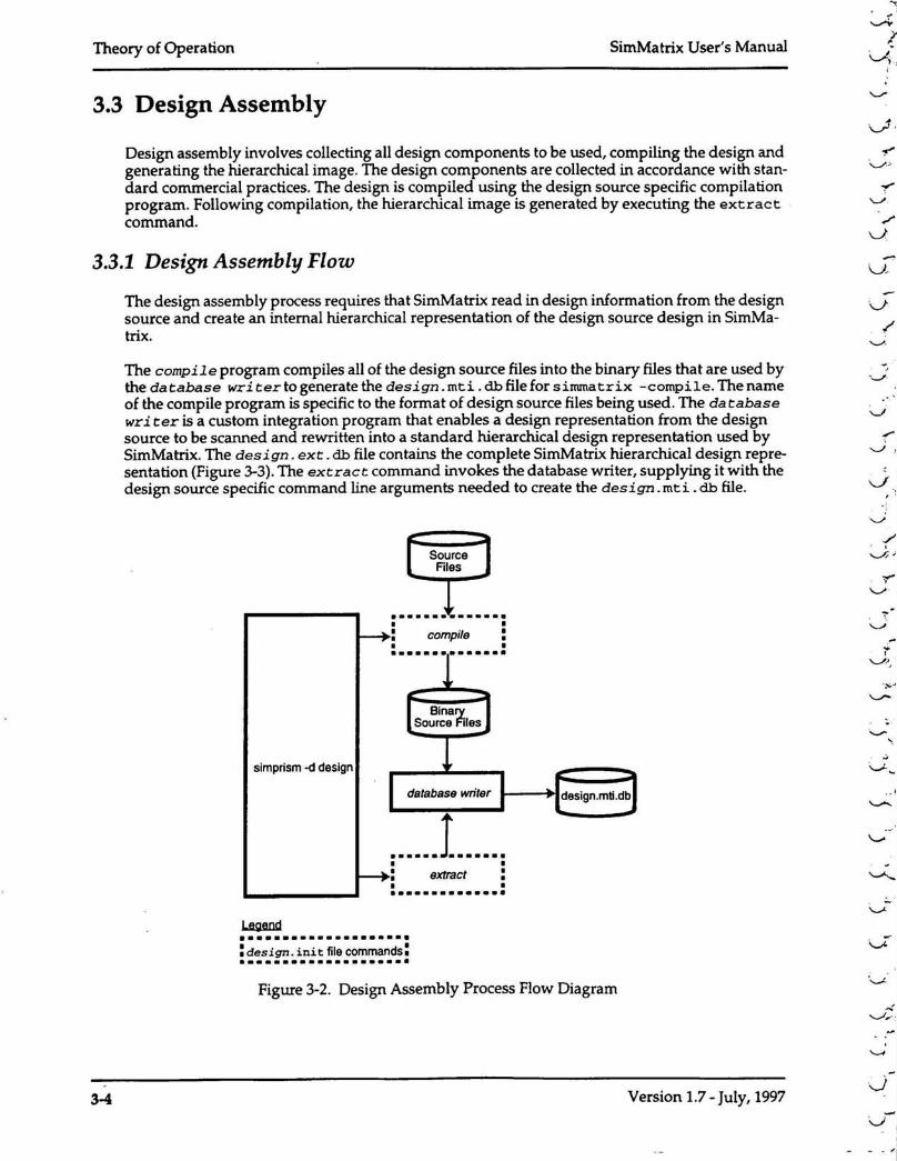
Design assembly involves collecting all design components to be used, compiling the design andgenerating the hierarchical image. The design components are collected in accordance with stan-dard commercial practices. The design is compiled using the design source specific compilationprogram. Following compilation, the hierarchical image is generated by executing the extractcommand.
3.3.1 Design Assembly Flow
The design assembly process requires that SimMatrix read in design information from the designsource and create an internal hierarchical representation of the design source design in SimMa-trlx.
The compile program compiles all of the design source files into the binary files that are used bythe database wri terto generate the design.mti. db file for sirmnatrix -compile. The nameof the compile program is specific to the format of design source files being used. The da tabasewri ter is a custom integration program that enables a design representation from the designsource to be scanned and rewritten into a standard hierarchical design representation used bySimMatrlx. The design. ext. db file contains the complete SimMatrix hierarchical design repre-sentation (Figure 3-3).The extract command invokes the database writer, supplying it with thedesign source specific command line arguments needed to create the design. mt i .db file.
•............•• •: compile :• ••......•.....•
simprism -d design
......1 .• •: extract :• ••............•
•••••..........••..•: design. init file commands:•....•••.........•.•
Figure 3-2. Design Assembly Process Flow Diagram
/"
J
'-/'
.r,"'-.-/ .,1
: '
\..../
,-
''-'''""
.• ,1
00'
'-'"
..........,:,.
3-4 Version 1.7 - July, 1997

SimMatrix User's Manual Theory of Operation
,.
"--'
..~-, ,
'}-I
NOTEThe translation of design source design representation into the SimMatrix DataBase design representation is controlled by processes that were developed forthe specific design source to SimMatrix integra tion being used. These processesare described in the SimMatrix Database Iritegration manual, PN IM002.
Figure 3-3. SimMatrix Database Design Representation (design.ext.db)
3.4 Partitioning
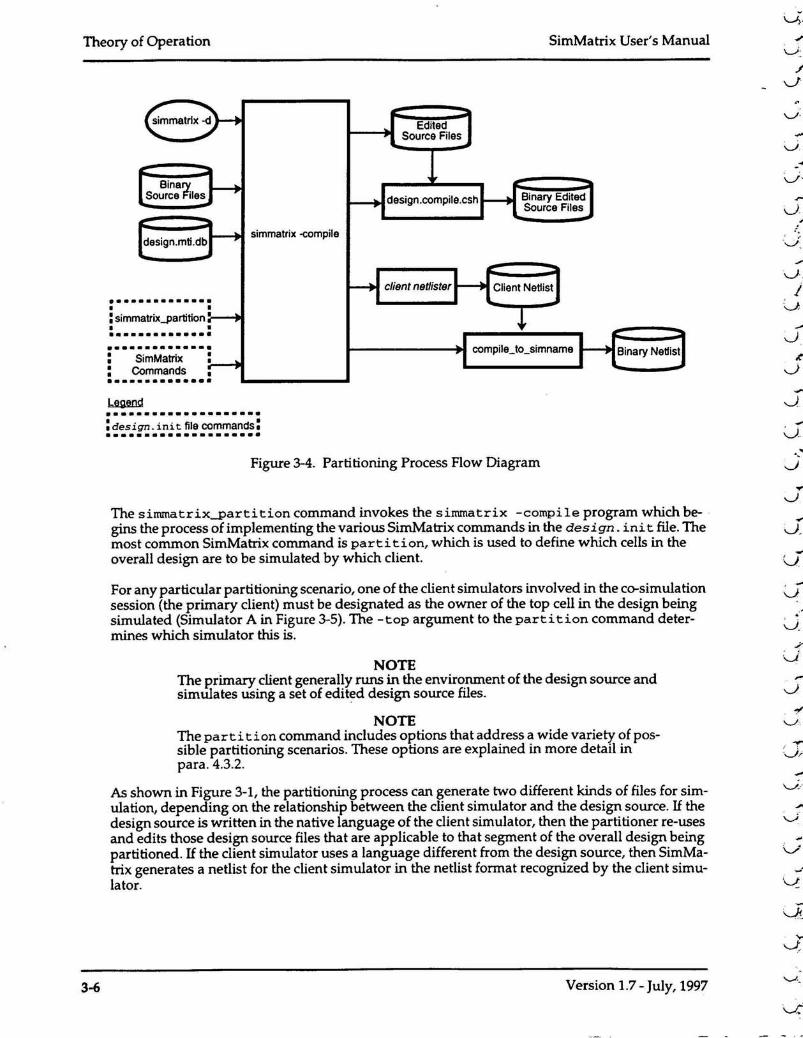
When SimMatrix is invoked by entering the simmatrix -d design command (Figure 3-4), thecommands in the design. init are sourced by the simmatrix -compile program whichlaunches SimMatrix processes to generate the appropriate client netlist file(s) for each integratedclient. As shown in Figure 3-4, the sourced commands from the des ign. ini t file (shown en-closed by dotted lines) represent user inputs to the partitioning process.
Figure 3-4 illustrates the elements involved in the overall partitioning process. The SimMatrixpartitioning tool automates the partitioning process by implementing partition rules that are an-notated to native design source files (Appendix A) and/ or placed in the design. ini t file. Fromthis information, SimMatrix identifies all design blocks pertaining to each simulator, determinesall nets that cross simulator boundaries (mixed nets), and automatically generates inter-simulatorconnectivity information for the integrated clients. SimMatrix then generates the appropriatenetlist files to be simulated by each client.
Version 1.7 - July, 1997 3-5
Theory of Operation SimMatrlx User's Manual
/J
...
.~
\.j.j
Jclient net/istef
simmatrix -compile
•............•• •: simmatrixJlartition •• ••.......••••.••............•: SimMatrix :: Commands ••............••..................•: design. ini t file commands:•..................•
Figure 3-4. Partitioning Process Flow Diagram
The simmatrix-partition command invokes the simmatrix -compile program which be-gins the process of implementing the various SimMatrlx commands in the design. ini t file. Themost common SimMatrlx command is parti tion, which is used to define which cells in theoverall design are to be simulated by which client.
For any particular partitioning scenario, one of the client simulators involved in the co-simulationsession (the primary client) must be designated as the owner of the top cell in the design beingsimulated (Simulator A in Figure 3-5). The -top argument to the partition command deter-mines which simulator this is.
.-J
NOTEThe primary client generally runs in the environment of the design source andsimUlates using a set of edited design source files.
NOTEThe parti tion command includes options that address a wide variety of pos-sible partitioning scenarios. These options are explained in more detail inpara. 4.3.2.
As shown in Figure 3-1, the partitioning process can generate two different kinds of files for sim-ulation, depending on the relationship between the client simulator and the design source. If thedesign source is written in the native language of the client simulator, then the partitioner re-usesand edits those design source files that are applicable to that segment of the overall design beingpartitioned. If the client simulator uses a language different from the design source, then SimMa-trlx generates a netlist for the client simulator in the netlist format recognized by the client simu-lator.
J
....V
,-
3-6 Version 1.7 - July, 1997

The client netlister is a custom integration program that enables a SimMatrlx hierarchicaldesign representation (created by the database writer) to be written into a hierarchical design rep-resentation format that is recognized by the client simulator.
..vL
SimMatrix User's Manual Theory of Operation
NOTEThe translation of SimMatrix hierarchical design representation into a clientnetlist format is controlled by the processes that were developed for the specificclient simulator to SirnMatrlx integration being used. These processes are de-scribed in the SimMatrlx Integration Development Environment manual, PN!MOO I.
Some of the other SimMatrix commands that can be sourced are described in Chapter 4.
Figure 3-5. Possible Design Partitioning Scenario
Desi~n Partition toSimulator B
Desi~n Partition toSimulator A
, ..
-v Figure 3-6 shows the design representations that are created for two client simulators based onthe partitioning rules shown in Figure 3-5. SimMatrix retains name space mapping in the designpartitions by adding the necessary levels of hierarchy from the design partition to the top cell inthe original unpartitioned design (Figure 3-3). This is only required for those clients not owningthe top cell in the overall design.
Also, if additional levels of design hierarchy exist in the client representation, below what couldbe represented in the original design source, then that portion of the client netlist can be importedand attached (in native client netlist code) to the generated client netlist (Figure 3-7).
Version 1.7 - July, 1997 3-7

During partitioning SimMatrix creates a shadow representation of the design segments partitionedto all other simulators and attaches this to the design representation used by the primary client(Figure 3-6). The shadow design representation enables the primary client's environment to inter-act with the corresponding cells in the design segments partitioned to the other integrated simu-lators. This interaction depends on the capabilities of the primary client's environment and caninclude such things as dropping probes, monitoring waveforms, inputting stimulus, etc.
Theory of Operation
3.4.1 Shadow Generation for Exported Blocks
SimMatrlx User's Manual
Added To PreserveName Space Mapping
Simulator B
, ;'I\...A..
rl
'-'"\,.r.1v.'
.•.-1,~
3-8
ShadowNetlist
Figure 3-6. Shadow Generation for Exported Block
Version 1.7 - July, 1997
I-....A
;
.,

,"--/SimMatrix User's Manual
3.4.2 Placeholder Generation for Imported Blocks
Theory of Operation
The partitioning function allows for the design representation of cells from within the partitionedblock to be imported from an outside library, rather than being determined by the overall designrepresentation. For example, if a particular cell is instantiated from a library in the client simulator(Simulator C), the partitioning function can be specified to import the description of the cell fromthe imported library instead of the overall design representation (Figure 3-7).This way the netlistcreated for the client only instantiates the specific cell, not the netlist hierarchy underneath it.
Any design representation in the primary client below the imported block is pruned from the pri-mary client and a placeholder is created in the primary client for the cell designated as an import.Since imported blocks have no design representation in the primary client, they are not directlyaccessible for interaction with the primary client's environment.
......."
Simulator A
SimulatorC
Figure 3-7. Placeholder Generation for Imported Block
Version 1.7 - July, 1997
ImportedBlock
3-9

Theory of Operation SimMatrix User's ManualI'---.;
I!J'-" "'.
3.4.3 Distributed Simulation
Partitioning a design involves specifying the design object to be partitioned and the target simu-lator that will simulate that object. Specifying the target simulator involves defining the clientsimulator as well as the host computer and cpu process that the client will be running on. Theclient simulator taken in conjunction with the host computer and cpu process define the targetsolver for a particular design partition.
There are primarily two types of designs that are good candidates for distributed simulation:
• large designs with partitions exceeding available memory.• designs using slower, high accuracy simulators, e.g., SPICE.
Figure 3-8. Partitioning for Distributed Simulation
....
v.
--J'
Host 1Local Host(Default)
Client ClientSocket Socket Partition 1
Interface Interface Client 1
Host 2
Client ~ ClientPartition 2Socket Socket
Interface~
Interface Client 2
I- - - ----_.Client ~ Client Partition 3Socket ~ Socket
Interface Interface Client 3
Partition 8 SimMatrixClient 1 Host 3
Client Client Partition 4Socket Socket Client 2
Interface Interface CPU Process 1
-- 1-----Client Client Partition 5Socket Socket Client 2
Interface Interface CPU Process 2
- - 1-----Client Client Partition 6Socket , Socket Client 3
Interface Interface CPU Process 3
The concept of a solver as the target for a design partition provides the vehicle that enables designpartitions to be simulated on different hosts and even different cpu processes within a host. Thisenables large designs to be segmented for simulation across a network of hardware systems. Italso enables a partition being simulated by a slower, high accuracy simulator to be performed ona faster machine.
Figure 3-8 illustrates a complex partitioning scenario that utilizes all of the parameters for speci-fying a target solver (client, host, cpu process). During the partitioning, SimMatrix creates a clientsocket interface for each solver so that it can communicate back and forth with each partition. Ascan be seen from the illustration, different client simulators can be run on different process withinthe same host.
3-10 Version 1.7 - July, 1997

SimMatrix User's Manual Theory of Operation
Chapter 5 provides information on how to obtain maximum performance using distributed sim-ulation.
3.4.4 Legal Partitions
SimMatrix supports virtually any partitioning scheme that the user can devise. This includes nest-ed design partitions (donuts) and isolated partitions (islands) (Figure 3-9).
Client 2Island
Prima!}'Client 1 (TOp)
Nested Partition(Donut)
Client 1
Client 2Island
Figure 3-9. Legal Partitions
3.4.5 Conflicts
The client integration to SimMatrlx handles conflicts between simulators regarding such issues asobject names, design representation, and representation of nets and ports. If problems revolvingaround these issues do occur, please consult your integration engineer.
Version 1.7 - July, 1997 3-11

Theory of Operation
3.5 Co-simulation
SimMatrlx User's Manual
IJ
~.'.
v.
After successfully partitioning the design in preparation for co-simulation, the user can invokeSimMatrix to perform co-simulation (para. 3.2.1.2). The co-simulation process breaks down intoinitialization and runtime stages. Figure 3-10 shows a typical functional flow for a co-simulationsession.
3.5.1 Initialization Stage
The initialization stage goes through the following processes:
• Initialize client• Parse netlist• Registering mixed nets, probes, and breakpoints.• Initialize simulator state• Find initial starting point
A simulation session begins with SimMatrix instructing each client simulator initializing. SimMa-trix then instructs each client to open one or more netlist files created by the netlist writer, andparse their contents. Upon completion of the parsing function, SimMatrix instructs each client toregister all mixed nets, probes, and breakpoints in its design partition.
NOTEMixed nets must be registered during the initialization stage whereas probesand breakpoints can be registered during the initialization stage or they can beinjected during the runtime stage (para. 3.5.2.1).
SimMatrix then instructs each client to initialize its circuit partition to some initial operating point.This resets each client's notion of time to 0, releases all forced values on probes, and initializes thestate of every net. In digital simulators, the initial state of every net is usually defined by thesimulator. For analog simulators, the initial state of every net results from finding a stable dcoperating point for the circuit.
Each simulator performs at least one initialization cycle. At the end of this initialization, the re-sulting states of mixed nets are exchanged between simulators. After any resultant state changeshave been made and the dc solution settles, SimMatrlx begins to coordinate the active co-simula-tion session.
.•...U
./• <
-u-,
v.'
./'"0
'-..J./
--.).
J/
3-12 Version 1.7 - July, 1997J
'--./

SimMatrix User's Manual
Initialization
Synchronize clients.Transfer signal state to SimMatrix.
YES
Theory of Operation
------- ....( simmatrix -d design. I----- ---
Initialize clients.
Parse netlists.
Register mixed nets, probes andbreakpoints.
Initialize state on all nets.
Load simulation related commandsfrom design.init file
Co-simulate.
r
••
- - --User events
-------Enter command(s)Resume simulation-------
....*,- ., ....,•••• Session ,I+- YES....4, interrupted? •••••- .. , ...., ....
lo....*,.... ,•••• Session ,
NO ~, terminated? •••••, ...., ....vTs
Exit simulation session.
'~
Version 1.7 - July, 1997
Figure 3-10. Co-simulation Flow
3-13

Theory of Operation
3.5.2 Runtime Stage
SimMatrix Vser's ManualJ
rI
J,
After initialization, the runtime stage starts up as a regular simulation session in the environmentof the primary client (the client owning the top cell of the overall design). When SimMatrix detectsa mixed net to a design segment partitioned to another simulator, it transfers control of the co-simulation session to that simulator. During the co-simulation session, only the User Interface(VI) of the controlling simulator is active.
While the co-simulation session is running, each client simulates that portion of the overall designpartitioned to it until a boundary event (mixed net) is encountered. When a mixed net (spanningsimulators) is encountered, SimMatrix synchronizes the simulators and distributes boundaryevent information (such as states, currents, or voltages) across simulators. A user-programmablestate translation table provides for consistent signal representation between simulators. SimMatrixarbitrates state changes on mixed nets to determine which simulator drives a mixed net.
Synchronization is required so that boundary event information occurs in all simulators at thesame point in time. SimMatrlx manages the synchronization of integrated simulators based on aninternal time tick of one femtosecond (1fS).SimMatrlx also provides for the selection of an event-based synchronization scheme to optimize performance.
The mechanism used to gather and transfer boundary events varies from one simulator to anoth-er, and can occur through direct memory transfer (subroutine or shared memory implementa-tion) or through inter-process communication (over Ethernet), if multiple workstations are beingused. SimMatrlx automatically selects the highest performance communication vehicle availablefor each simulator. The simulation session appears identical regardless of the communication ve-hicle utilized.
The event transfer process continues through the entire simulation session, pausing only if the de-signer wishes to interrupt and interact with the co-simulation session. When the simulation ses-sion terminates, all intermediate files that were created are deleted and all of the simulators beingused are terminated.
If no breakpoints are triggered, simulation time advances until the specified interval elapses, atwhich point the simulation terminates and control is returned to the user.
3.5.2.1 Boundary Event Processing
Signal states are communicated to and from SimMatrix when boundary events (mixed nets, probednets, or breakpoints) are encountered. Mixed nets are defined during the netlisting process andare registered during initialization of the co-simulation session (para. 3.5.1).Probed nets and break-points can be registered during initialization or incrementally after a co-simulation session begins.
Every time a signal (mixed net, probe or breakpoint) is communicated to or from SimMatrix, astate translation function is executed.
When a client is simulating and it encounters a mixed net, probe or breakpoint, it drives the netby forcing a new state on that net and passes the value to SimMatrix, so that SimMatrlx canpropagate the change in state of the net to other simulators.
.-v-,
•..J
J
. -J
..•J
J
-J...
J
J
('.J
-Jf
J
J
J<..'-..;,
3-14 Version 1.7 - July, 1997
J
J

SimMatrix User's Manual
3.5.2.1.1 State Translation
Theory of Operation
Signal state representation, while consistent within anyone particular simulator, varies betweendiverse simulators, especially if one of the simulators is digital and the other is analog. As such,it is critical that signal states being passed between diverse simulators (on mixed nets) be asconsistent as possible. This consistent signal state representation is achieved by point-to-pointsignal mapping between simulators, or by mapping to the SimMatrix intermediate type, SxDigital(Figure 3-11).
•
L-L.I:...../
Point to Point Type Conversion
Type Conversion Using SimMatrix Abstract Data Types
Figure 3-11. Type Conversions using Point to Point and SimMatrix Intermediate Types
The point to point type conversion produces the best co-simulation performance because only asingle conversion process needs to be executed. Converting to SimMatrix intermediate types re-quires a dual conversion process from Mysim to the intermediate types and then from the inter-mediate types to another simulator. The benefit of converting a simulator's types to the SimMatrixintermediate types is that it will be compatible with any other simulator whose types have alsobeen converted to the SimMatrix intermediate types. In such a case, a direct point to point con-version path does not have to be available between integrated simulators. The default type map-pings can be changed by using the remap_type command (Table 4-1).
,."-../
Version 1.7 - July, 1997 3-15

Theory of Operation
3.5.2.1.2 Mixed Nets
SimMatrix User's Manual
Mixed nets are registered as in, out, or bidirectional types. An in mixed net means that thestate of that mixed net in the client gets changed to something else via SimMatrix. An out mixednet means that the client provides the source of a state change to an associated mixed net viaSimMatrix. A bidirectional mixed net can both be changed and be the source of a change from/toSimMatrix.
Signal flow direction between components connected by mixed nets is the same as signal flow di-rection between those components in the original design source. If SimMatrix cannot determinesignal direction during partitioning, it will be assigned to be bi-directional.
3.5.2.1.3 Probes
Probes are normally placed by a user to collect simulation (waveform) data for display on thescreen. SimMatrix monitors all probed nets and report any state/voltage changes occurring at theprobed net in a similar manner as the reported state changes for outgoing or bidirectional mixednets.
3.5.2.1.4 Breakpoints
Breakpoints are used to detect certain state conditions within the design, and typically to takesome action, such as issuing an interrupt, when the state has been detected. When a breakpoint isencountered, the breakpoint reports a state change to SimMatrix in a similar way the state changesare reported for mixed and probed nets.
3.5.2.2 Synchronization
When a boundary event occurs between integrated simulators, SimMatrix synchronizes the inte-grated simulators so that they are at the same point in time. lbis enables data to be reliably ex-changed between integrated simulators.
SimMatrix uses two types of synchronization schemes; 1) look-ahead and 2) optimistic. Look-ahead synchronization is used for digital simulation and optimistic synchronization is used foranalog simulation. In a mixed simulation (digital and analog co-simulators) environment, a look-ahead or optimistic synchronization will take place, depending on which simulator contains thesynchronizing boundary event. If it is the digital simulator, the analog simulator will employ opti-mistic synchronization to synchronize to it. If it is the analog simulator, the digital simulator willemploy look-ahead synchronization to synchronize to it.
3.5.2.2.1 Look-ahead Synchronization
Look-ahead synchronization allows co-simulators to execute asynchronously until a boundaryevent (requiring synchronization) is reached. Between synchronization points, each co-simulatoroperates sequentially with the other simulators, the sequence being determined by which simu-lator has the next event to be processed.
SimMatrix arbitrates between the integrated clients to determine which simulator has will havethe next event to be processed and instructs that simulator to simulate until it's next event.
lbis process repeats for the next closest next event (among all connected simulators), until a bound-ary event is encountered. When a boundary event is encountered, all simulators, except the onethat advanced to the next (boundary) event, will advance to the time of the boundary event, andall simulators will be synchronized to the same time.
-J
J
J.
~J.
J
J
J
J,..:
3-16 Version 1.7 - July, 1997

SimMatrix User's Manual Theory of Operation
,.,-,
E2 SimA E6 SimAE9
SimA II ., II .1 H
I I BoundaryE4 Sim B I , / Event.1 E7,
SimB II i 1,1, II SimC I
E1 E3 E51 I EaSimC H H II .' H
,/Boundary
Event
Figure 3-12. Look-Ahead Synchronization
3.5.2.2.2 Optimistic Synchronization
During optimistic synchronization, each of the co-simulators advance (in parallel) through nextevents until they encounter a boundary event. The times of each simulator boundary event areprovided to SimMatrix for arbitration so that SimMatrix can determine which simulator encoun-tered a boundary event at the earliest time. The time of the earliest encountered boundary eventbecomes the synchronizing boundary event, i.e., the time to which all the other co-simulators mustsynchronize.
LastSynchronized
Event
SimASynchronizing
BoundaryEvent
t1IIISimA
SimB
t2III
I Advance/' Time t3
k~-~••..---- .'m"=-I
SimBTime Step
Figure 3-13. Optimistic Synchronization
The client with a later occurring boundary event is instructed to backup to its last event thatoccurred prior to the synchronizing boundary event. The co-simulators must then simulate from thepoint in time backtracked to, to the same time as the synchronizing boundary event.
Version 1.7 - July, 1997 3-17

Theory of Operation SimMatrlx User's Manual
3.5.2.2.3 Event-Based Synchronization
In some cases, a design partition exists on a synchronous boundary between two cells wherecommunication is important only when a clock occurs. For example, a pipe lined multiplier maygenerate many intermediate results on its output before a clock latches a final result. Normally,boundary event traffic and synchronizations are required for each of the intermediate results, eventhough the data has no immediate value, until the clock latches the final result.
In this situation, you might be able to reduce backplane overhead by using event-based synchro-nization, which specifies the signal (event) to synchronize on. Event-based synchronization re-duces the number of synchronizations, but has no affect on event traffic.
SimMatrix provides the sync_signal command (para. 4.3.3.2) that can be used to set the Sim-Matrix synchronizations to occur during specific boundary events.
3.5.2.3 Interrupt Handling
An interrupt can be issued at any time during a co-simulation session from the controlling clientenvironments. An individual solver can be interrupted asynchronously by using it's native inter-rupt facility (usually <CTRLC» from within its own control window, or synchronously by issuingthe SimMatrix pause command from any of the other clients control window to the target client.
Both types of interrupts disable all other client environments and suspend the co-simulation ses-sion until the interrupted client resumes the co-simulation session.
Asynchronous interrupts retain simulation control for the interrupted client. Synchronous inter-rupts propagate the interrupt from one client to the other and simulation control is retained bythe interrupting client.
Asynchronous interrupts can be issued by a controlling simulator at any time during a co-simu-lation session.
A synchronous interrupt is immediately propagated to the targeted client, where it is serviced assoon as it is safe to do so.
Two conditions can cause a delay before an interrupt; 1) the targeted client might process inter-rupts only at designated times, and 2) co-simulator synchronization might delay the servicing ofthe interrupt until the client is active.
During an interrupt, the interrupted client can issue new simulator commands that will be prop-agated into the co-simulation session once the co-simulation session is resumed. Those com-mands can be issued directly to the client controlling the co-simulation session, or they can bepropagated to any other client involved in the co-simulation session.
Resuming from an interrupt (whether asynchronous or synchronous) gives control back to the in-terrupting clients environment.
3.5.2.4 Debugging
SimMatrix preserves the User Interface (UI) and debugging systems used by a client, but they areonly active when that client has control of the simulation. As a result, if a synchronous interruptis issued from another client, then the issuing client has control of the simulation, and graphicalwaveform functions for the interrupted client will be disabled until it has control of the simula-tion.
,.;
V
'--', I
'--~1JjJ
J
J
3-18 Version 1.7 - July, 1997
SimMatrix User's Manual Theory of Operation
SimMatrix debugging commands to add/delete breakpoints and probes, and to view nets andports can be issued to any client in the co-simulation session.
When encountered, breakpoints issue a synchronous interrupt to the client in which the break-point occurred.
The design environment of the primary client can be used to examine the overall design hierarchyand signal states for those portions of the overall design exported to another client. Signals thatspan multiple simulator boundaries can be debugged in the environment of any affected client.
3.5.2.5 Injecting a Stimulus (Driving a Mixed Net)
A client can use its native signal stimulus facility (or external command files) to inject (drive) astimulus value onto any net in its own design partition hierarchy. This includes nets that have ac-cess to mixed nets and therefore could get propagated into another client's design partition. Inorder for an injected stimulus to drive an associated mixed net, the injected stimulus must followthe signal design flow (directionality) of the associated mixed net.
3.5.2.5.1 Sample Signal Injection
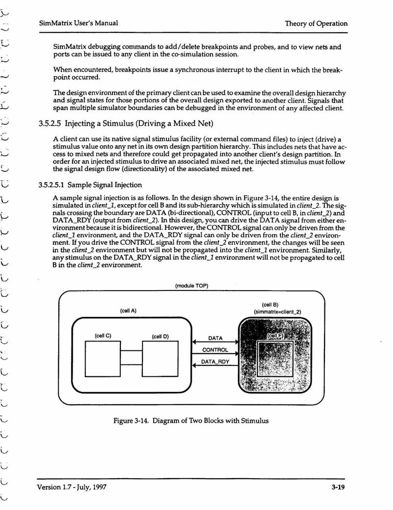
A sample signal injection is as follows. In the design shown in Figure 3-14, the entire design issimulated in clienCl, except for cell Band its sub-hierarchy which is simulated in clienC2. The sig-nals crossing the boundary are DATA (hi-directional), CONTROL (input to cell B,in client_2) andDATA_ROY (output from client_2). In this design, you can drive the DATA signal from either en-vironment because it is bidirectional. However, the CONTROL signal can only be driven from theclient_l environment, and the DATA_ROY signal can only be driven from the client_2 environ-ment. If you drive the CONTROL signal from the client_2 environment, the changes will be seenin the client_2 environment but will not be propagated into the clienCl environment. Similarly,any stimulus on the DATA_ROYsignal in the clienCl environment will not be propagated to cellB in the clienC2 environment.
(module TOP)
1_11_1'L-L
(cell C)
(cell A)
(cell D) DATACONTROL
DATA_ROY
(cell B)(simmatrix=clienC2)
Version 1.7 - July, 1997
Figure 3-14. Diagram of Two Blocks with Stimulus
3-19

Theory of Operation SimMatrix User's Manual
This situation can be circumvented by changing CONTROL and DATA_ROY into bidirectionalsignals. This can be done by adding the add_mixed_net command into the design. ini t file asfollows:
These changes take effect after re-partitioning the design. This changes the direction of the CON-TROL and DATA_ROYsignals from unidirectional to bidirectional. Note that there is a small per-formance penalty associated with changing a unidirectional signal into a bidirectional signal sinceevents must now propagate into both directions.
3.5.3 Tenninating a Co-simulation Session
A co-simulation session can be terminated by shutting down SimMatrix or any of the client sim-ulators. When SimMatrix recognizes that any of the simulators involved in the co-simulation ses-sion has terminated, it instructs all other simulators to terminate the session in an orderly manner.
''-..J-
J.•.
v.
,:.
J
3-20 Version 1.7 - July, 1997