chapter 3: structural requirements 3.1 general 3.2 …
TRANSCRIPT

1
CHAPTER 3: STRUCTURAL REQUIREMENTS
3.1 GENERAL
The structural design of the SS tower shall take into account both the vertical and lateral
loads, where applicable.
The SS tower shall be designed for maximum degrees of redundancy in the structural
system against weapon effects.
3.2 MATERIALS
3.2.1 Concrete
The minimum grade of concrete for all SS elements shall be C32/40. The use of pre-
stressed concrete for SS wall/slab and NS wall/slab in the SS, S/C SS or scissor S/C SS
tower is not permitted.
3.2.2 Steel Reinforcement
The steel reinforcement in SS/NS wall and slab shall be welded steel fabric mesh for steel
bar diameter of up to 16mm and hot rolled steel bars. The minimum yield stress of main
reinforcement bars and shear links in the structural elements forming the SS, S/C SS or
scissor S/C SS or NS shall be minimum 500 N/mm2.
3.3 ANALYSIS
3.3.1 General
The vertical continuity of SS and NS walls, where applicable, to the foundation shall
comply with clause 2.4.2.
In the case of S/C SS or scissor S/C SS tower, the SS and NS wall shall be continuous
to foundation.
3.3.2 Beam Supported on SS wall
The end of the external beam that is supported on SS wall(s) shall be designed and
detailed as simply support.

2
3.3.3 Shielded NS Walls and/or NS columns
(NS columns not applicable to S/C SS or scissor S/C SS Tower)
No additional design checks on SS tower is required if its supporting elements, wall(s),
column(s) or any of its combination, are shielded. These structural elements are deemed
shielded if reinforced concrete slab or other equivalent structural forms provided above
them is extended beyond their edges by as minimum length of 0.5H, where H is the
aggregate wall height of NS (See FIGIURE 3.3.3).
3.3.4 Unshielded NS Walls and /or NS Columns
(NS columns not applicable to S/C SS or scissor S/C SS Tower)
The following requirements are to be complied with if the design adopts:
(a) & (b) Unshielded NS Walls (4 NS walls or 2 opposite NS walls)
The minimum thickness of each NS wall shall be 300mm. The SS, S/C SS or
scissor S/C SS tower shall be designed against the most severe effects as the result
of the removal of a portion of the NS wall equivalent to an opening of 1500mm
diameter on the NS wall at its most critical location (Refer to FIGURE 3.3.4(a)
and FIGURE 3.3.4(b)).
(c) Unshielded NS Columns
The minimum size (either its diameter or the shorter dimension) of each NS
column shall be 500mm. The SS tower shall be designed against the most severe
effects as the result of the removal of any one NS column (Refer to FIGURE
3.3.4(c)).
(d) Combination of Unshielded NS Walls and NS Columns
The minimum thickness of each NS wall and minimum size (either its diameter
or the shorter dimension) of each NS column shall be 300mm and 500mm
respectively. The SS, S/C SS or scissor S/C SS tower shall be designed against
the most severe effects as the result of the following (Refer to FIGURE 3.3.4(d)).
(i) Removal of a portion of the NS wall equivalent to an opening of 1500mm
diameter at its most critical location and
(ii) Removal of any one NS column
The above item (i) and (ii) shall be considered mutually exclusive.
(e) The following are the criteria to be used when performing design checks for
Clause 3.3.4(a), 3.3.4(b), 3.3.4(c) or 3.3.4(d):
(i) The design shall be based on the action combination and values of partial
safety factor for actions in accordance with Table 3.3.4.

3
(ii) The design strength for a given material is derived from the characteristic
strength divided by the partial safety factor for strength of material, which
shall be 1.2 for concrete and 1.0 for reinforcements.
3.4 MEMBER DIMENSIONS AND REINFORCEMENT REQUIREMENTS
3.4.1 Member Dimensions
The minimum member size of SS and NS shall be as stipulated in Chapter 2 - Architectural
Design.
3.4.2 Reinforcement Requirements
All diameters of reinforcement specified hereinafter shall refer to minimum fabric mesh
or bar diameters. All spacing of reinforcement specified hereinafter shall refer to
maximum spacing of reinforcement in both directions.
3.4.2.1 Wall Reinforcements of SS and NS
(a) Minimum Reinforcement in SS or NS walls - refer to TABLE 3.4.2.1.
(b) Reinforcements at both faces of the internal common wall shall be H10-100
c/c in both faces. The shear links shall be H8-600 c/c in both directions.
3.4.2.2 Slab Reinforcements of SS and NS Slabs
(a) Intermediate SS/NS slabs and slabs/waists of staircase SS/NS:
Top and bottom layer of slab reinforcements shall be H10-100 c/c in both
directions. The shear links shall be H8-600 c/c in both directions.
(b) Ceiling slab of top-most SS:
(i) Reinforcements at both external face and internal face of the slab shall be
H13-100 c/c (both directions);
(ii) The shear links shall be H8-600 c/c in both directions
(c) Floor slab of bottom-most SS or NS and floor slab of NS located above an SS:
(i) Slab reinforcements at both external face and internal face shall be H13-
100 c/c (both directions);
(ii) The shear links shall be H8-600 c/c in both directions
(d) Ceiling slab outside the SS tower which is immediately above SS door:
The minimum ceiling slab shall be constructed of 150mm thick reinforced concrete.
The reinforcement shall consist of two layers of reinforcement (top and bottom) at

4
H10-100 c/c in both directions. These top and bottom layers of reinforcement bars
shall be continuous or anchored to the slab of SS with tension anchorage length.
(e) Floor slab outside SS tower:
The reinforcements of every floor slab immediately outside SS tower walls shall be
structurally connected to the SS tower.
(f) SS slab which is integrated with pile-cap/footing:
For SS slab integrated with the pile-cap or footing of 500mm thick or more, shear
links is not required. The maximum spacing of main reinforcement shall be 200 c/c.
(g) Shielding wall in front of SS door:
Reinforcements at both faces of the wall shall be minimum H10-200 c/c. The shear
link with L-bend at two ends shall be H8 at 600 c/c in both directions.
3.5 DETAILING OF SS TOWER
3.5.1 General
The SS tower is to be detailed to allow for the installation of services and fixtures in SS
and to resist spalling of the internal face of SS walls, soffit of ceiling slabs and/or finishes
on SS floor slab.
3.5.2 Lap and Anchorage Length
(a) Full lap and anchorage length of reinforcements in SS and NS walls and slabs shall
be provided. The lap length shall take into account good or poor bond condition,
steel bar diameter, shape of steel bar, concrete cover, steel strength and location
where reinforcement bar laps and confinement of transverse bars.
(b) Minimum tension lap and anchorage length of reinforcement bars for minimum
concrete grade C32/40 with good bond condition shall be as shown in TABLE
3.5.2. Longer tension lap and anchorage length shall be provided if they are
required to meet poor bond condition and/or the structural load and safety
requirements.
(c) Welding of reinforcement to attain full anchorage length and tension lap length is
not permitted.
(d) Bundled bars are not permitted.

5
3.5.3 Concrete Cover
The minimum and maximum concrete cover to the main reinforcements shall be 25mm
and 40mm respectively.
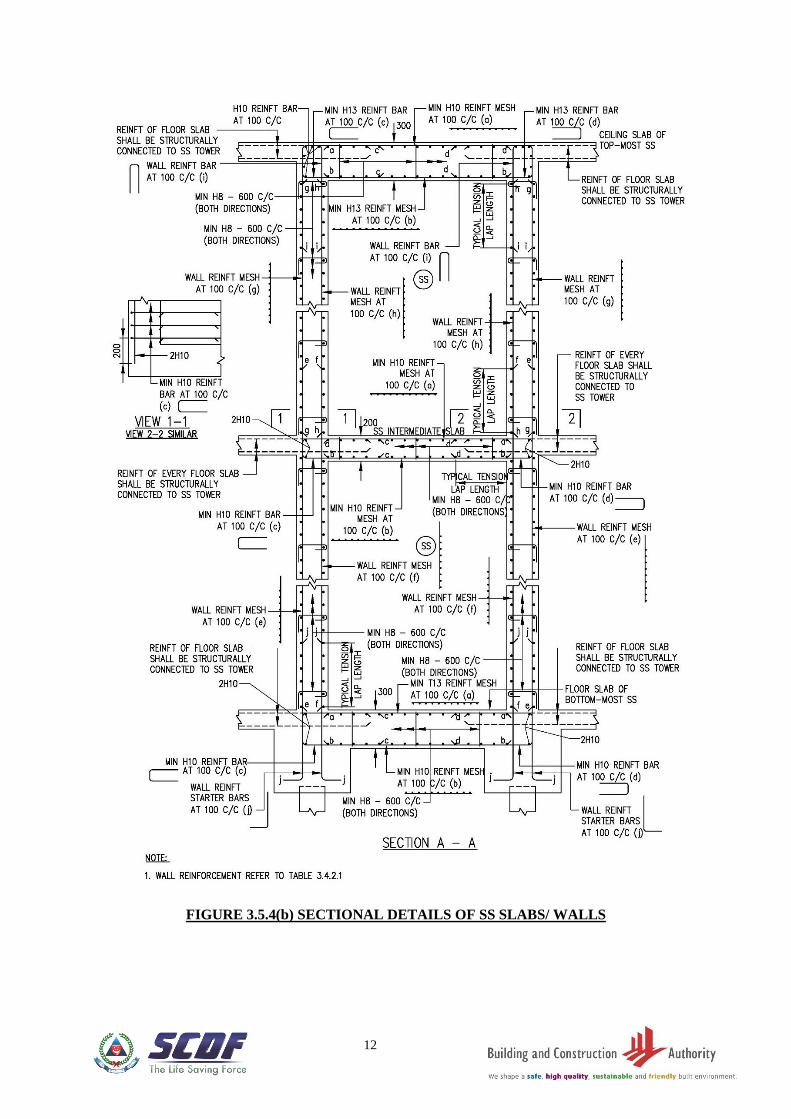
3.5.4 Cast-In-Situ Elements for SS and S/C SS
Cast-In-Situ for SS elements shall comply with the dimensions and detailed
requirements as shown in the following figures:
FIGURE 3.5.4(a) - Plan of SS wall
FIGURE 3.5.4(b) - Typical details of SS slabs/walls
FIGURE 3.5.4(c) - Typical details of SS slabs/walls
FIGURE 3.5.4(d) - Details of SS wall reinforcement bars near SS door
FIGURE 3.5.4(e) - Typical details of embedded conduit in SS wall
FIGURE 3.5.4(f) - Typical details of trimmer bars for ventilation sleeve
F FIGURE 3.5.4(g) - Typical details of trimmer bars for wall recess
FIGURE 3.5.4(h) - Details of shear kinks in SS slabs/walls
FIGURE 3.5.4(i) - Details of SS slab reinforcement near rescue hatch
FIGURE 3.5.4(j) - Reinforcement plan details for S/C SS
FIGURE 3.5.4(k) - Sectional details of SS slabs/walls for S/C SS
FIGURE 3.5.4(l) - Sectional details of SS slabs/walls for S/C SS
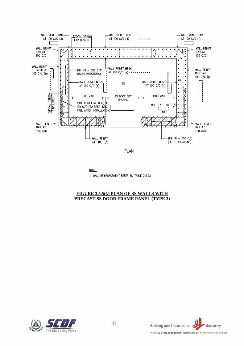
3.5.5 Precast Elements for SS and S/C SS
Pre-cast SS elements shall comply with the dimensions and detailed requirements as
shown in the following figures:
FIGURE 3.5.5(a) - Plan of SS walls with precast SS door frame panel (Type 1)
FIGURE 3.5.5(b) - Details and sections of precast SS door frame panel with
ventilation sleeve above it (Type 1)
FIGURE 3.5.5(c) - Sections of precast SS door frame panel with ventilation sleeve
above it (Type 1)
FIGURE 3.5.5(d) - Details and sections of precast SS door frame panel with
ventilation sleeve along its side (Type 1)
FIGURE 3.5.5(e) - Details and sections of precast SS door frame panel with
ventilation sleeve along its side (Type 1)
FIGURE 3.5.5(f) - Plan of SS walls with precast SS door frame panel ((Type 2)
FIGURE 3.5.5(g) - Details and sections of precast SS door frame panel with
ventilation sleeve above it (Type 2)
FIGURE 3.5.5(h) - Sections of precast SS door frame panel with ventilation sleeve
above it (Type 2)
S FIGURE 3.5.5(i) - Details and sections of precast SS door frame panel with
ventilation sleeve along its side (Type 2)
FIGURE 3.5.5(j) - Sections of precast SS door frame panel with ventilation sleeve
along its side (Type 2)
FIGURE 3.5.5(k) - Plan of SS walls with precast SS door frame panel (Type 3)
FIGURE 3.5.5(l) - Details of precast SS door frame panel (Type 3)
F FIGURE 3.5.5(m) - Sections of precast SS door frame panel (Type 3)

6
FIGURE 3.5.5(n) - Sections of precast SS door frame panel (Type 3)
3.5.6 Joints
(a) Construction joints in an SS tower shall be properly executed to ensure that the
strength and the integrity of the SS are not impaired. The type and location of joints
shall be specified in the design after taking into account the following:
(i) A concrete kicker, if provided, shall not be more than 100mm high.
(ii) All SS walls located within each storey shall be cast in one operation.
(b) Expansion joints or contraction joints in the SS tower are not permitted.
3.6 PENETRATION OF SERVICES
3.6.1 Electrical Services
All service conduits shall not penetrate through the walls and slabs of the SS. Service
conduit for electrical and communication fixtures which are located on external SS wall
can be embedded in the SS wall. Other than this, all services conduit which do not serve
the SS shall not embed within the SS wall and slab.
Two cast-in embedded sockets mounted directly back to back on the internal and
external faces of the SS wall are not permitted. Where sockets are to be mounted on
both the internal and external faces of an SS wall, they shall be mounted at least 300mm
apart from each other, measured between their clear edges. Refer to FIGURE 3.6.1(a)
Risers for electrical services may be mounted on the external face of SS tower walls.
Where fixture in the SS are exposed on internal walls and slab, non-metallic inserts are
to be used for their mounting. For embedded service cables and fixtures serving the SS,
the details shall be as shown in FIGURE 3.5.4(e). The encasement of switch socket
outlets, TV and radio outlets, communication line for telephony outlet and switches of
Clause 2.6 shall be galvanised steel. Refer to FIGURE 3.6.1(b).
A maximum of five numbers of 25mm diameter service conduits for electrical cables
serving the SS are allowed to be embedded in the SS structural elements. Both ends of
the concealed conduits shall be fully sealed with approved sealing material of up to a
depth of not less than 100mm into the conduits to ensure air-tightness of the SS.
Where an SS or NS share a common wall with lift shaft or service risers, mounting of
services on the common wall is allowed on the external face of SS or NS wall. For the
purpose of installing M&E equipment in the lift core or service risers, hot-dipped
galvanised cast-in bar with threaded end shall be used in this common wall. Where anchor
bolts are used, they shall be installed according to manufacturer’s technical specification.
The spacing the anchor bolts, measured between their centrelines, shall not be less than
300mm.

7
3.6.2 Water and Gas Services
Water and gas services are allowed to pass through the SS walls provided that they are
laid within a stainless steel conduit encased by 150mm reinforced concrete all round.
Refer to FIGURE 3.6.2. Joints in pipes or the stainless steel conduit shall be located
outside the SS. Risers for services can be mounted on the external face of SS tower
walls.

8
TABLE 3.3.4: ACTION COMBINATION AND VALUES OF PARTIAL SAFETY
FACTORS FOR ULTIMATE LIMIT STATE
Action
Combination
Permanent Action Variable Action
Earth/Water
Pressure Load,
if applicable Favourable Unfavourable
Imposed
Load Wind Load
Permanent and
Variable
(Imposed Load,
Wind Load),
Earth/Water
Pressure Load, if
applicable)
1.0 1.0 1.0 1.0 1.0
TABLE 3.4.2.1: MINIMUM REINFORCEMENTS OF SS OR NS WALLS
SS/NS Clear Height
(mm)
Reinforcement at both internal and
external face of wall
(both directions)
Shear Links
(both directions)
2400 ≤ Ht ≤ 3400 H13 - 100 c/c H8 - 600 c/c
3400 < Ht ≤ 3900 H16 -100 c/c H8 - 600 c/c
TABLE 3.5.2: MINIMUM TENSION LAP AND ANCHORAGE LENGTH
Type
Reinforcement Bar Diameter Ø (mm)
10 ≤ Ø ≤ 16 16 < Ø ≤ 32
Lap Length 47Ø 52Ø
Anchorage Length 37Ø 37Ø

9
SECTION
FIGURE 3.3.3 SHIELDED NS WALLS AND/OR NS COLUMNS (NS COLUMNS NOT APPLICABLE TO S/C SS OR SCISSOR S/C SS TOWER)

10
FIGURE 3.3.4(a) UNSHIELDED
NS WALL(S)
FIGURE 3.3.4(b) UNSHIELDED NS
WALL(S)
FIGURE 3.3.4(d) COMBINATION OF
UNSHIELDED NS WALL(S) AND/OR NS
COLUMN(S) (NS COLUMNS NOT APPLICABLE TO S/C SS OR
SCISSOR S/C SS TOWER)
FIGURE 3.3.4(c) UNSHIELDED
NS COLUMN(S) (NS COLUMNS NOT APPLICABLE TO S/C SS OR
SCISSOR S/C SS TOWER)

11
FIGURE 3.5.4(a) PLAN OF SS WALL
12
FIGURE 3.5.4(b) SECTIONAL DETAILS OF SS SLABS/ WALLS

13
3.5.4(c) SECTIONAL DETAILS OF SS SLABS/ WALLS

14
FIGURE 3.5.4(d) DETAILS OF SS WALL REINFORCEMENT BARS NEAR SS DOOR

15
FIGURE 3.5.4(e) TYPICAL DEATILS OF EMBEDDED CONDUIT IN SS WALL

16
FIGURE 3.5.4(f) TYPICAL DETAILS OF TRIMMER BARS
FOR VENTILATION SLEEVE
FIGURE 3.5.4(g) TYPICAL DETAILS OF TRIMMER BARS FOR WALL RECESS

17
FIGURE 3.5.4(h) DETAILS OF SHEAR LINKS IN SS SLABS/ WALLS

18
FIGURE 3.5.4(i) DETAILS OF SS SLAB REINFORCEMENT NEAR RESCUE HATCH

19
FIGURE 3.5.4(j) PLAN OF SS WALL FOR S/C SS

20
FIGIURE 3.5.4(k) SECTIONAL DETAILS OF SS SLABS/ WALLS FOR S/C SS

21
FIGURE 3.5.4(l) SECTIONAL DETAILS OF SS SLABS/ WALLS FOR S/C SS

22
FIGURE 3.5.5(a) PLAN OF SS WITH PRECAST SS DOOR FRAME PANEL (TYPE 1)

23
FIGURE 3.5.5(b) DETAILS AND SECTIONS OF PRECAST SS DOOR FRAME PANEL
WITH VENTILATION SLEEVE ABOVE IT (TYPE 1)

24
FIGURE 3.5.5(c) SECTIONS OF PRECAST SS DOOR FRAME PANEL
WITH VENTILATION SLEEVE ABOVE IT (TYPE 1)

25
FIGURE 3.5.5(d) DETAILS AND SECTIONS OF PRECAST SS DOOR FRAME WITH
VENTILATION SLEEVE ALONG ITS SIDE (TYPE 1)

26
FIGURE 3.5.5(e) DETAILS AND SECTIONS OF PRECAST SS DOOR FRAME WITH
VENTILATION SLEEVE ALONG ITS SIDE (TYPE 1)

27
FIGURE 3.5.5(f) PLAN OF SS WITH PRECAST SS DOOR FRAME PANEL
(TYPE 2)

28
FIGURE 3.5.5(g) DETAILS AND SECTIONS OF PRECAST DOOR FRAME PANEL WITH
VENTILATION SLEEVE ABOVE IT (TYPE 2)

29
FIGURE 3.5.5(h) SECTIONS OF PRECAST SS DOOR FRAME PANEL
WITH VENTILATION SLEEVE ABOVE IT (TYPE 2)

30
FIGURE 3.5.5(i) DETAILS AND SECTIONS OF PRECAST SS DOOR FRAME PANEL
WITH VENTILATION SLEEVE ALONG ITS SIDE (TYPE 2)

31
FIGURE 3.5.5(j) SECTIONS OF PRECAST SS DOOR FRAME PANEL
WITH VENTILATION SLEEVE ALONG ITS SIDE (TYPE 2)
32
FIGURE 3.5.5(k) PLAN OF SS WALLS WITH
PRECAST SS DOOR FRAME PANEL (TYPE 3)

33
FIGURE 3.5.5(l) DETAILS OF PRECAST SS DOOR FRAME PANEL (TYPE 3)

34
FIGURE 3.5.5(m) SECTIONS OF PRECAST SS DOOR FRAME PANEL (TYPE 3)

35
FIGURE 3.5.5(n) SECTIONS OF PRECAST SS DOOR FRAME PANEL (TYPE 3)

36
FIGURE 3.6.1(a) MOUNTING OF SERVICES ON EXTERNAL WALL OF A SS

37
FIGURE 3.6.1(b) TYPICAL DETAILS OF EMBEDDED SOCKET/ SWITCH

38
FIGURE 3.6.2 ENCASEMENT DETAILS OF WATER/ GAS SERVICE PIPES
PENETRATING THROUGH SS WALLS