chapter 3 design for construction - seattle.gov home
TRANSCRIPT

SPU Design Standards and Guidelines Chapter Owner-Alissa Lee November 2020 3-i
Chapter 3 Design for Construction
Chapter 3 Design for Construction ............................................................... 3-1
3.1 Key Terms ...................................................................................................................... 3-1
3.1.1 Abbreviations ........................................................................................................................................ 3-1
3.2 Construction Engineering and Quality Management ................................................ 3-3
3.3 Level of Completeness .................................................................................................. 3-5
3.3.1 Design During Construction ............................................................................................................. 3-5
3.3.2 Use of “To be determined by the Engineer” ................................................................................. 3-6
3.4 Presentation Standards................................................................................................. 3-6
3.4.1 Notes ...................................................................................................................................................... 3-7
3.4.2 Asset Identifications ............................................................................................................................ 3-7
3.5 Survey Controls ............................................................................................................. 3-8
3.6 Construction Staging, Laydown and Equipment ....................................................... 3-8
3.7 Construction Stormwater and Pollution Prevention ................................................ 3-9
3.7.1 Construction Stormwater and Erosion Control Plan ................................................................ 3-10
3.7.2 Tree, Vegetation, and Soil Protection Plan ................................................................................... 3-11
3.7.3 Spill Plan ............................................................................................................................................... 3-12
3.7.4 Temporary Discharge Plan .............................................................................................................. 3-12
3.7.5 Dewatering Plan ................................................................................................................................. 3-15
3.8 Demolition, Removals, and Deconstruction ............................................................. 3-16
3.9 Underground Considerations ..................................................................................... 3-16
3.9.1 Hazard Analysis .................................................................................................................................. 3-17
3.9.2 Excavation and Shoring ..................................................................................................................... 3-18
3.9.3 Utility Locates, Relocations, Protection, and Coordination During Construction.............. 3-20
3.9.4 Settlement Monitoring ...................................................................................................................... 3-22
3.9.5 Charged Water Mains ....................................................................................................................... 3-23
3.9.6 Asbestos Pipe Abandonment and Disposal .................................................................................. 3-23
3.9.7 Confined Spaces ................................................................................................................................. 3-23
3.10 Above-Ground Considerations .................................................................................. 3-24
3.10.1 Poles and Guy Wires ........................................................................................................................ 3-24
3.10.2 Overhead Wiring ............................................................................................................................... 3-25
3.10.3 Buildings ............................................................................................................................................... 3-25
3.10.4 Walls and Bridges .............................................................................................................................. 3-26
3.10.5 Railroads .............................................................................................................................................. 3-26
3.10.6 Hillsides ................................................................................................................................................ 3-26
Chapter 3 Design for Construction
3-ii SPU Design Standards and Guidelines Chapter Owner: Alissa Lee November 2020
3.11 Sewer and Drainage Bypasses .................................................................................... 3-27
3.12 Maintain Water Service .............................................................................................. 3-28
3.12.1 Construction Sequencing to Minimize Service Disruptions to Water Customers ............. 3-28
3.12.2 Temporary Services .......................................................................................................................... 3-29
3.13 Working in a Creek or Stream .................................................................................. 3-30
3.13.1 Fish and Permits ................................................................................................................................. 3-30
3.13.2 Stream Bypass ..................................................................................................................................... 3-31
3.13.3 The Art of Stream Structure Placement ....................................................................................... 3-32
3.13.4 Access Considerations ..................................................................................................................... 3-32
3.13.5 Measure and Payment ....................................................................................................................... 3-32
3.14 Working in the Watershed ........................................................................................ 3-33
3.15 Geotechnical Services ................................................................................................. 3-34
3.15.1 Provide Available Project Information ........................................................................................... 3-35
3.15.2 Available Subsurface Information ................................................................................................... 3-35
3.15.3 Additional Subsurface Information ................................................................................................. 3-35
3.15.4 Construction Support ....................................................................................................................... 3-36
3.16 Traffic and Public Access ............................................................................................ 3-37
3.16.1 Work Sequence and Staging ............................................................................................................ 3-37
3.16.2 Traffic Control Plans ......................................................................................................................... 3-37
3.16.3 Temporary Pavement........................................................................................................................ 3-39
3.17 Site Restoration ........................................................................................................... 3-40
3.18 Inspection, Testing, and Rejection Criteria .............................................................. 3-41
3.19 Final Acceptance Procedures ..................................................................................... 3-41
3.19.1 Sewer Lining Projects ........................................................................................................................ 3-42
3.19.2 Spot Sewer Repair Projects and New Drainage and Wastewater Pipes ............................... 3-42
3.19.3 Water Mains ....................................................................................................................................... 3-42
3.19.4 Bioretention and Biofiltration ......................................................................................................... 3-43
3.20 Resources ...................................................................................................................... 3-44
Appendices Appendix 3A - Two Sample Construction Stormwater Plans Appendix 3B - Sample Notes for Construction Stormwater and Erosion Control Plans Appendix 3C - Sample Notes for Water Plans Appendix 3D - Sample Notes for Water Services Appendix 3E - Sample Notes for Drainage Plans About Catch Basins and Inlets Appendix 3F - Sample Notes for Sewer and Drainage Plans About Mainlines Appendix 3G - Sample Notes for Side Sewers Appendix 3H - Sample Notes for Pavement Plans, Including Metro Coordination Appendix 3I - Sample General Notes

Chapter 3 Design for Construction
SPU Design Standards and Guidelines Chapter Owner: Alissa Lee November 2020 3-iii
List of Figures Figure 3-1 Limited Site Access .................................................................................................................................... 3-8 Figure 3-2 Compost Sock Around Grate Outside of Travel Lane .................................................................... 3-11 Figure 3-3 Settling Tanks Need Space ..................................................................................................................... 3-13 Figure 3-4 Boiling Sands Along the Duwamish ...................................................................................................... 3-15 Figure 3-5 Offset MH Cone Between Two Ducts................................................................................................ 3-18 Figure 3-6 MH Cone in Conflict with Gas and Duct (Modified) ....................................................................... 3-18 Figure 3-7 Trench Box Without Ground Support ............................................................................................... 3-19 Figure 3-8 Water Main Supported with Nylon Strap ........................................................................................... 3-20 Figure 3-9 Beam and Strap Utility Support ............................................................................................................ 3-20 Figure 3-10 Damage and Danger to Conduit ........................................................................................................ 3-22 Figure 3-11 Low Electrical Service ........................................................................................................................... 3-25 Figure 3-12 Excavation Next to a Building ............................................................................................................. 3-26 Figure 3-13 Trench Side View ................................................................................................................................... 3-26 Figure 3-14 Fish Removal in Conjunction with Bypass ........................................................................................ 3-31 Figure 3-15 Stream Bypass Intake ............................................................................................................................ 3-31 Figure 3-16 Hand-carried Logs for Stream Structure .......................................................................................... 3-32 Figure 3-17 Conduit Installation on Tolt Dam Lake ............................................................................................. 3-33 Figure 3-18 In-Water Barge Operations on Chester Morse .............................................................................. 3-33 Figure 3-19 Residential Street Closure ................................................................................................................... 3-38 Figure 3-20 Temporary Pedestrian Bridge ............................................................................................................. 3-38 Figure 3-21 Temporary Crushed Rock Pavement ................................................................................................ 3-40

Chapter 3 Design for Construction
SPU Design Standards and Guidelines Chapter Owner: Alissa Lee November 2020 3-1
Chapter 3 DESIGN FOR CONSTRUCTION
This chapter of the Design Standards and Guidelines (DSG) presents standards and guidance for project constructability for Seattle Public Utilities (SPU) facilities. The primary audience for this chapter is SPU engineering staff. DSG standards are shown as underlined text.
Choices made during the design process not only determine what the final product is and how it functions but also influence the Contractor’s selection of equipment, working hours and schedules, risks, liabilities and insurance needs, and, of course, bids. Contractors want fewer constraints, an easy place to set up and, generally, the quickest way to complete the project. Design engineers must balance the purposes of the project and the requirements of the permits with the desires of the Contractor, to minimize construction costs and impacts. The costs of the temporary parts of the work, such as shoring or traffic control, can be much more expensive than the final product. When designing for construction, design engineers should aim to meet the following constructability goals:
• Ensure that there is at least one practical way to build the design. • Make the drawings and contract documents clear to all parties.
Optimize the balance between the project’s and Contractor’s needs to minimize costs and impacts to the environment, to the customers, and to the public.
3.1 KEY TERMS Abbreviations and definitions given here follow either common American usage or regulatory guidance. See Standard Plan 002 for abbreviations for general use on drawings.
3.1.1 Abbreviations Abbreviation Term AC asphalt concrete
ACI American Concrete Institute
ADA Americans with Disabilities Act
APWA American Public Works Association
BMPs best management practices
CAM Client Assistance Memorandum
CB Catch basin
Chapter 3 Design for Construction
3-2 SPU Design Standards and Guidelines Chapter Owner: Alissa Lee November 2020
Abbreviation Term CDF controlled density fill
City City of Seattle
CO change order
CMD Construction Management Division
CPM Critical Path Method
CSEC Construction Stormwater and Erosion Control
CSGP Construction Stormwater General Permit
CSO combined sewer overflow
CY Cubic yard
DC design change
DWW drainage and wastewater
Ecology Washington State Department of Ecology
EPA U.S. Environmental Protection Agency
GIS Geographic Information System
HDPE high-density polyethylene
KCIW King County Industrial Waste
I&C instrumentation and controls
Metro King County Metro Transit Department
MH maintenance hole
NPDES National Pollutant Discharge Elimination System
O&M operations and maintenance
PCC Portland cement concrete, Point of Compound Curve
PIT pilot infiltration test
PVC Polyvinyl Chloride
PSE Puget Sound Energy
RFI request for information
ROW right-of-way
SCADA supervisory control and data acquisition
SCL Seattle City Light
SDCI Seattle Department of Construction & Inspections
SDOT Seattle Department of Transportation
SIP Street Improvement Permit
SPU Seattle Public Utilities
TCP Traffic Control Plan

Chapter 3 Design for Construction
SPU Design Standards and Guidelines Chapter Owner: Alissa Lee November 2020 3-3
Abbreviation Term TVSPP Tree, Vegetation, and Soil Protection Plan
UIC underground injection control
WMBE Women and Minority-Owned Business Enterprise
3.2 CONSTRUCTION ENGINEERING AND QUALITY MANAGEMENT
The construction supervisor assigned to each project is the most valuable resource for a design engineer when considering constructability and how to design and prepare specifications for construction. The Construction Management Division (CMD) has documented some best practices and expectations in three documents:
• SPU Construction Management Quality Manual • SPU Office Engineering Manual • Construction Engineering Inspector’s Quality Assurance Handbook
Each project must consider how to staff the construction management team, determining the level of inspection required and who can provide expertise for complex project elements. Early identification of the project inspection needs and discussion can help the project manager and construction supervisor locate internal and external resources to support construction management. For inspections that are outside of construction management’s core work of water, drainage, and wastewater, additional inspection resources may be required. The resident engineer is not automatically expected to perform several inspection roles, and thus may need additional resources to complete, including:
• Commissioning Authority, including equipment testing and system testing and operations and maintenance (O&M) manuals.
• Electrical, including code and compliance with SPU standards. • Instrumentation and controls (I&C) and supervisory control and data acquisition
(SCADA). • Landscaping. • Communications. • Special inspection required by permit or regulation, such as Seattle Department of
Construction & Inspections (SDCI). • Structural or architectural, including mockups and coating inspections to meet
owner/designer requirements. • Geotechnical, including piling, infiltration testing, or on-site checking of subgrade for
green stormwater best management practices (BMPs), such as for bioretention and protection of infiltrating soils.
• Settlement and vibration monitoring. • Special survey. • Pollution prevention monitoring and reporting.

Chapter 3 Design for Construction
3-4 SPU Design Standards and Guidelines Chapter Owner: Alissa Lee November 2020
• Safety for augment compliance and documentation. • Historical or archaeological protections. • Specialty materials testing or review. If supplemental testing or review is required,
discuss with the SPU Materials Lab and the design team to determine the availability of acceptable products.
• Acting as the Commissioning Authority includes providing the commissioning plan, witnessing and verifying equipment, system, and operational testing; training Operations staff; and reviewing the O&M manuals. The Commissioning Authority, not the RE, is responsible for:
− Planning and coordinating the commissioning process. − Providing the commissioning plan. − Organizing and leading the commissioning team and the team’s meetings. − Informing involved parties on the status, integration, and performance of
systems within the facility. − Developing the project-specific construction checklists and commissioning test
procedures. − Verifying the execution of commissioning activities by reviewing equipment
submittals, the construction checklists, training materials, O&M data, commissioning schedule, test procedures and test reports to verify compliance with the project owner’s requirements.
− Monitoring the status of the construction checklist to ensure that all requirements of the construction process are achieved prior to the beginning of facility startup.
− Recommending the involvement of facility Operations personnel in the commissioning process and coordinating training of Operations personnel on each system, as necessary.
− Witnessing and verifying the equipment acceptance testing, system acceptance testing, and operational acceptance testing as needed and recommending final acceptance to the RE.
− Reviewing and commenting on the equipment O&M manual submittals. − Preparing the final commissioning report and recommending acceptance of the
facility to the project manager. − Providing technical expertise to oversee and verify correction of deficiencies
found in the commissioning process. − Assisting with resolution of commissioning related disputes.
Most projects require survey, and all should have record drawings. Some may require additional or independent survey verification or record drawings, which may be just a step in finalizing the project commissioning. For clarity, discuss the options and requirements in the bid documents and for staffing the construction management team.

Chapter 3 Design for Construction
SPU Design Standards and Guidelines Chapter Owner: Alissa Lee November 2020 3-5
Tips: Consider developing internal and external communications plans. External communications for larger projects with community impacts may require additional staffing during construction. Internal communications about roles, standards and expectations can become complex with larger construction support teams. Identifying a resource need in the middle of construction can be detrimental to the success of a project. When relying on consultants, a plan can help identify needed individuals, skill sets, and scope.
Despite electrical work passing inspection, SPU electricians have had to rework the wiring to meet operational and uniformity needs. Consider how electrical inspections will be staffed and do not rely on the American Public Works Association (APWA) standard specifications.
3.3 LEVEL OF COMPLETENESS Contract documents are never complete, and a project that strives for design perfection will generally not get built. Design for clarity and make conscious decisions about how much investigation and design polishing is needed for clear construction documents and to limit changes during construction. Consider the tradeoffs in time (now vs. later), as well as design costs (now vs. payments to the Contractor, because additions and changes after bidding creation increased cost.
3.3.1 Design During Construction During construction, the design team should be able to provide timely support and contributions to the following documents:
Submittals. Standard contract requirements can be found in City of Seattle (City) Standard Specification section 1-05.3. In most cases, the engineer of record will be responsible for review of all technical submittals, including most items with special provisions noted. Some examples are shop drawings, Contractor designs, and technical procedures. For complex projects, the design team should prepare a submittal control document (or draft control document) for inclusion in the Project Manual, since the design team is more familiar with the contract requirements at time of bid and award. A draft document can be amended and submitted by the Contractor. During construction, this document will be used by CMD and the Contractor to track submittals.
The SPU Materials Lab generally reviews submittals for materials with well-established specifications.
Tip: There are two types of material submittals: source forms and material specific information. A source form simply allows a material to come from a given supplier; the material specific submittals include specific information about a given material. SPU CMD staff will approve source forms. The design team may approve some material-specific submittals. If the specification calls for submittal of a sample, be clear about who will receive the sample and provide acceptance.
Requests for Information (RFIs). The Contractor generally submits RFIs when some element of work is not clear to the Contractor. Often, the resident engineer will ask for design team input. An RFI is not an authorization for added work or increased contract cost.

Chapter 3 Design for Construction
3-6 SPU Design Standards and Guidelines Chapter Owner: Alissa Lee November 2020
Design Changes (DCs). DCs typically follow an RFI. DCs are issued when some design or contract issue needs to be clarified or altered. A DC may authorize additional work and costs by the Contractor.
Change Orders (COs). COs follow DCs. A DC may request a cost proposal, while a CO will require and define added work and include how that work will be paid for. COs include one or more of the following three elements:
1. No cost. Changing a Women and Minority-Owned Business Enterprise (WMBE) subcontractor, adding time, or a cost neutral change in contract requirements.
2. Credit. A reduction in cost either from the deletion or replacement of some parts of the contract.
3. Additive. An increase in contract value.
3.3.2 Use of “To be determined by the Engineer” The plans and Project Manual need to define the work for bidding, so there are limited situations where it is reasonable to say “To be determined by the Engineer”:
• Where the units for the associated work are unit costs, and the resident engineer (or other pre-determined project team members) will determine the exact location of unit cost items.
• Where the work cannot be quantified at the time of bid and there is a force account bid item associated with the work. In this case, the design team would set a fixed value for the force account item.
• Where the work has been quantified and specified but the project team wants to control the product and direct the Contractor. Work as directed by the Commissioning Authority is one example. Similar to a force account, the design team would set a fixed value for the directed work.
Ensure that the construction manager on the project team is notified when “To be determined by the Engineer” is used.
3.4 PRESENTATION STANDARDS This section describes standards for drawings, notes, and specifications details the importance of format for the City’s record keeping and for communications with the Contractor. See section 4.2 of DSG Chapter 4, General Design Considerations.
Tips: Make an early decision and revisit the question of what type of contour information is appropriate for the project. For roadway projects, contour lines are not standard (profiles and curb return data are), but many consultants will propose drainage and grading sheets that may not be a good communication tool for the Contractor or surveyors. For earthwork, ask how many points and how much staking might be needed? Will the Contractor need to work from a civil 3-D model? Which elevations and contours are critical and may need verification by an independent survey?

Chapter 3 Design for Construction
SPU Design Standards and Guidelines Chapter Owner: Alissa Lee November 2020 3-7
When designing slopes, keep the slope angle changes to a minimum. For example, in swales it is much easier to set two points for a slope, top and bottom, than it is to add intermediate slope break points. It is hard to dig a slope with an excavator with multiple slope break points.
It is much easier to work in the field off multiple plan sheets, such as removal, utilities, landscaping, and paving, when all sheets have the same scale, stationing, and match lines. There have been many cases when the landscape drawings were in a different scale and with different match lines than the utilities or there were conflicts between the civil grading and utility drawings. Because they are difficult to cross check, these conflicts may not be encountered until construction.
3.4.1 Notes Notes can be a useful addition to clarify or highlight requirements. Notes can also be used to reduce plan sheet clutter and create a global annotation (e.g., materials). Develop and edit notes carefully, since notes can also create confusion or unintentionally modify contract requirements.
Appendices 3B, 3C, 3D, 3E, 3F, 3G, 3H, and 3I include sample note sets that may be useful as a starting point when determining what notes make sense for the project. Except for Appendix 3I - Sample General Notes for use when applying for a Street Improvement Permit (SIP), these notes should not be imported to the drawings. They are examples and may contain inconsistencies.
Generally, notes that are required to obtain a permit should be incorporated into the contract. A major exception is the note sets Seattle Department of Transportation (SDOT) makes available for developers on its SIP website. The notes for water and drainage were developed specifically in the context of a development permit, not City projects and should not be in the drawings even when requested by SDOT’s Street Use department. SDOT’s set of SIP general notes includes language that contradicts the basic contract, especially about the authority of the engineer. Appendix 3I - Sample General Notes includes a set of modified SIP general notes that are a better match with a City project and have been approved by SDOT’s Street Use department.
Tips: Be specific when writing notes. Be aware of how each note is backed up within the drawings and technical specifications. Beware notes that could be construed as repeating or modifying Division 1 or the general provisions of the contract. Even though the specifications take precedence, that type of note creates confusion. Use supplementary specifications instead.
It is acceptable to reference out incidental specifications to the Seattle Standards from a CSI project manual. For example, reference out if the paint specification for a building does not work for channelization in the street that is a small component of the work.
3.4.2 Asset Identifications A variety of asset identifiers are needed for construction. See sections 1.6.3.3 and 1.9.1.5 of DSG Chapter 1, Design Process.
Chapter 3 Design for Construction
3-8 SPU Design Standards and Guidelines Chapter Owner: Alissa Lee November 2020
3.5 SURVEY CONTROLS For information on survey monumentation and construction impacts, see the Survey Monument Protection page under Construction Resources.
Basemaps should show all existing monumentation and drawings should identify an expectation for each monument potentially disturbed by the construction. Avoid conflicts, especially sewer maintenance holes (MHs)—sewers are often under the monument—that would require permanently relocating a monument. It is easier for survey to tie out the location and restore the monument to its proper location or establish a reference monument after construction.
Clarity on survey expectations in the Project Manual is important and should be discussed with the SPU survey section. See Standard Specifications section 1-05.5 on construction stakes and discuss whether that specification covers the project needs.
Some projects, especially operable facilities, have critical control needs and SPU will require a high level of certainty about the location and elevation or relational elevations for programming and/or operating the facility. Consider adding a step and have it shown on the Critical Path Method (CPM) schedule for SPU survey or an independent surveyor to confirm the control information.
Tip: Timing of a post-construction survey is critical. It should be after construction but before live flows are introduced and before the SCADA programming.
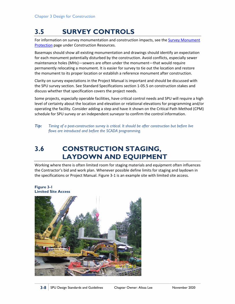
3.6 CONSTRUCTION STAGING, LAYDOWN AND EQUIPMENT
Working where there is often limited room for staging materials and equipment often influences the Contractor’s bid and work plan. Whenever possible define limits for staging and laydown in the specifications or Project Manual. Figure 3-1 is an example site with limited site access.
Figure 3-1 Limited Site Access
Chapter 3 Design for Construction
SPU Design Standards and Guidelines Chapter Owner: Alissa Lee November 2020 3-9
Tip: Where staging is limited and/or the project is linear, with some parts a significant distance from the staging area, consider designing with materials that can be installed or worked out of a dump truck. For example, because of staging limitations it may be more cost effective to haul out all excavated material and to backfill with imported material. Controlled density fill (CDF) placement requires the least amount of equipment.
Define a staging area in the Contract, if possible. When sizing the staging area, even if it is not included in the Contract, it is important to consider:
• Size of equipment • Depth of excavation • Overhead obstructions • Width of roadway • Spoils handling, including any special segregation of wastes • Materials storage • Site access and truck routes • Construction roads • Staging plan • Trenchless technologies space requirements • Construction offices • Power
3.7 CONSTRUCTION STORMWATER AND POLLUTION PREVENTION
Every construction project, regardless of size, is required to consider construction stormwater controls. For standard minimum contract requirements for Construction Stormwater Pollution Control Plans, see Standard Specifications sections 1-05.13(3), 1-07.5, 1-07.15, 1-07.16, and 8-01. For design guidance and checklists, see Volume 2, Construction Stormwater Control of the City of Seattle 2017 Stormwater Manual (Directors’ Rule 17-2017, DWW-200).
One approach is to review the 19 elements listed in Standard Specifications section 8-01.3(1) and document the response to these questions about each element:
1. Does this element apply to the project? 2. Is there a permit associated with this element, and, if so, will the project apply for the
permit, or require the Contractor to apply, or apply for the permit and amend the application with details only the Contractor can supply (most likely)? See DSG Chapter 2, Design for Permitting and Environmental Review.
3. What BMPs could be used to satisfy each requirement? What appears to be the cheapest or easiest to implement? Does the BMP require engineering and should the designer or Contractor be responsible for the engineering? What appears to be the most protective? How do the choices change through project phases? Will the Contractor’s choices be limited?

Chapter 3 Design for Construction
3-10 SPU Design Standards and Guidelines Chapter Owner: Alissa Lee November 2020
4. How are the choices, requirements and expectations for each element best presented to the Contractors: as a conceptual plan (preferred), notes, or specifications?
5. Does construction management concur that each element is enforceable with the proposed contract approach? Are specialists required for monitoring and documentation, and, if so, should those specialists be third party and what reporting relationship is appropriate?
3.7.1 Construction Stormwater and Erosion Control Plan
The preferred approach is for the design engineer to prepare a conceptual Construction Stormwater and Erosion Control (CSEC) plan. A contract that does not contain a conceptual CSEC plan or specific performance requirements carries risks to the environment, regulatory compliance, schedule, and budget. Without a conceptual plan, contractors will often submit a plan that is inadequate and may not be reasonably expected to bid an adequate plan by lump sum per Standard Specifications section 8-01.4.
Projects with very simple stormwater controls with few required elements and short timelines could summarize the requirements in notes. Or several conceptual plans for different phases could be required for more complex projects. For extreme risk cases, the team could choose to manage the work through force account.
A conceptual plan for the CSEC plan elements on the project site is preferred because it:
• Allows the designer to show minimum requirements and quantities with sufficient detail for bidding.
• Allows the designer to show sizing constraints. • Provides a drawing for review and checking constructability. • Allows the Contractor to modify and resubmit for review with all the other items
required by Standard Specifications section 8-01.3(2)A, which can simplify and speed up the review cycles considerably.
• Provides a drawing for permit reviewers, which is required for work on parcels.
Maintenance and removal requirements are typically handled with notes. Concrete washouts are typically identified by the Contractor and are not part of the conceptual plan.
See Appendix 3A - Two Sample Construction Stormwater Plans for two sample CSEC plans: Sample Water Main (curb and gutter roadway) and Sample Bioretention (ditch and culvert).
Tips: The most common construction BMP in the City is Protect Inlet, but too often in Seattle the inlet structure is too small (see Inlet type 164 and look for them in the field) to use a manufactured filter sock with an overflow, which is the only approved kind. Fabric under the inlet is still in widespread use but is not an approved BMP because it blocks the drainage function and is prone to spilling sediments into structures during handling. When the inlet is isolated from the traveled way, consider use of a compost sock around the grate (Figure 3-2). The BMP to clean inlets and CBs is not popular, but it works when protect inlet does not.
One common error in preparing a CSEC plan in the City is to fail to coordinate with the plan to maintain traffic and pedestrian access. See DSG section 3.16.2, Traffic Control Plans.

Chapter 3 Design for Construction
SPU Design Standards and Guidelines Chapter Owner: Alissa Lee November 2020 3-11
Figure 3-2 Compost Sock Around Grate Outside of Travel Lane
3.7.2 Tree, Vegetation, and Soil Protection Plan Standard contract requirements include provisions for a Tree, Vegetation, and Soil Protection Plan (TVSPP), which must be listed as a separate bid item, as needed. Consider providing a conceptual plan in the bid documents to communicate permit conditions, community expectations and details of protective measures in the bid documents. Often, the conceptual TVSPP information is shown with the CSEC plan or landscape plan. Especially, since most protective measures are fencing and exclusion, or soil amendment and new plantings.
For standard plans on tree protection during construction, see City Standard Plans 132 and 133. When the work could impact a planting strip, consider Option 2 of Standard Plan 132a. To fence off an entire planting strip instead of just around the trees for a conceptual TVSPP, avoiding compaction and disturbance of the planting strip soils reduces the additional work associated with amending the soil, planting, and landscape establishment.
Projects that are installing permeable pavements or any infiltrating BMP are required to protect or restore the infiltrative capacity of the soil. The BMP area should be protected from compaction or sedimentation or have requirements to restore the function. See Sample Bioretention CSEC plan in Appendix 3A - Two Sample Construction Stormwater Plans.
Tips: SDOT Urban Forestry is tasked with protecting street trees and can provide expertise early in the project for tree evaluations, tree trimming, tree moving, tree removals, and explaining the consequences of tree damage. After identifying any potential impact to street trees (remember to look up for backhoe to branch conflicts), inform the project manager that SDOT Urban Forestry’s assistance is required. It is better to work together to form a common vision with SDOT Urban Forestry during the design process than to argue with them after award. Managing tree conflicts during construction carries the risk of high cost and schedule impacts.
Be aware of “standard vertical clearances” if trees in the work zone are lower than standard vertical clearances. See Standard Specifications section 8-01.3(2)B, #1 in General Protective Measures.

Chapter 3 Design for Construction
3-12 SPU Design Standards and Guidelines Chapter Owner: Alissa Lee November 2020
3.7.3 Spill Plan Minimum requirements for a spill plan are described in Standard Specifications section 8-01.3(2)C. It is not standard practice to provide a conceptual spill plan in the bid documents. The project team should consider providing supplemental information and/or requirements for the spill plan when:
• Hazardous, dangerous, or contaminated materials are known to be on-site. At a minimum describe what is known and consider providing a waste characterization prior to the bidding. Note that different disposal sites have differing requirements and paperwork.
• Work is below a high-water line, near a waterway, or there are nearby sensitive areas, environmental critical areas, or complicated drainage pathways. Consider providing a site map beyond the construction zone for the Contractor’s use.
3.7.4 Temporary Discharge Plan The temporary discharge plan addresses all water generated during construction, including process water, stormwater, groundwater, and drinking water, to be discharged from a project:
• Process water. Wastewater produced by the project, including high pH water from stormwater in contact or associated with concrete operations and equipment, water generated from equipment and/or personnel decontamination activities (at sites with known soil and/or groundwater contamination issues), and highly chlorinated water used to disinfect water lines. Process water may be treated and discharged to the sanitary sewer or hauled offsite to an approved disposal facility, and it cannot be discharged to surface water. Effective temporary discharge plans minimize the amount of process water disposed by isolating the process water from other construction waters.
• Stormwater. Stormwater includes runoff from rain that falls on-site and run-on from areas outside the project area that should be diverted around the project to avoid comingling of on-site and offsite runoff. On-site stormwater includes:
− Contact stormwater, which is defined as runoff that has come in contact with contaminated soil with the potential to contribute contaminants to stormwater.
− Non-contact stormwater, which is runoff generated from existing paved surfaces and non-paved surfaces where soil is not known to be contaminated.
Contact stormwater should be managed separately from non-contact stormwater because it typically requires a higher level of treatment than non-contact stormwater. See section below on permitting for discussion of special discharge requirement for large sites or sites with known contamination issues. The CSEC plan should depict management and diversion of stormwater runoff through the construction site.
• Groundwater. Water encountered in open cuts and trenches as well as liquids generated when wet excavation spoils are dewatered prior to being hauled offsite for disposal. Solids must be able to pass the paint filter test (U.S. Environmental Protection Agency [EPA] Method 9095B) before they can be shipped offsite for disposal. Like stormwater, groundwater may contain contaminants that require higher levels of treatment before they discharge to either the drainage or sanitary/combined sewer system.

Chapter 3 Design for Construction
SPU Design Standards and Guidelines Chapter Owner: Alissa Lee November 2020 3-13
• Drinking water. Drinking water, when de-chlorinated, is a permissible discharge to the drainage system. Drinking water discharged to the sewer does not require de-chlorination, but large quantities may be subject to volume and flow rate restrictions. Drinking water discharges are generally the responsibility of SPU field operations and not the Contractor’s designated lead for temporary discharges.
Any water generated during construction that is discharged to the drainage system or nearby surface waters may be subject to flow restrictions depending on system capacity and the characteristics of the receiving water body. Regulations require that flow be controlled for discharges to small streams and rivers, but flow control is typically not required for discharges to large regional water bodies (e.g., Duwamish River, Elliott Bay, and Lake Washington). Water discharged from a construction site to the sanitary/combined sewer system will also be subject to flow restrictions depending on system capacity. The drainage and wastewater (DWW) line of business’ investigations and modeling team can provide discharge capacity limits for both the drainage and sewer systems.
Because City projects are often located in industrial areas and roadways that may be contaminated from historical activities, SPU recommends that site sampling and testing be conducted during the design phase to determine whether contamination is present at the project site in either soil or groundwater. Treatment costs and space requirements for siting of treatment system tanks and equipment should be considered during the design phase (Figure 3-3).
Figure 3-3 Settling Tanks Need Space
3.7.4.1 Permitting Considerations Discharges of construction water to the drainage and/or sanitary/combined sewer systems may trigger requirements for either a National Pollutant Discharge Elimination System (NPDES) Construction Stormwater General Permit (CSGP) from the Washington State Department of Ecology (Ecology) or a Discharge Authorization from King County Industrial Waste Program (KCIW).
Chapter 3 Design for Construction
3-14 SPU Design Standards and Guidelines Chapter Owner: Alissa Lee November 2020
NPDES CSGP permits are required under the following conditions:
1. Clearing, grading, and/or excavation that results in the disturbance of one or more acres (including offsite disturbance acreage authorized under section S1.C of the permit) and discharges of stormwater to surface waters of the State of Washington.
2. Any construction activity discharging stormwater to waters of the State of Washington that Ecology determines to be a significant contributor of pollutants or is reasonably expected to cause a violation of any water quality standard.
Note: Both CSGP permit conditions require that SPU submit a Notice of Intent (NOI) to obtain a CSGP. NOIs must include a certification form that is signed by the Project Delivery and Engineering Branch Deputy Director. NOIs can be submitted electronically via Ecology’s Water Quality Permitting Portal. See DSG Chapter 2, Design for Permitting and Environmental Review for further permitting information.
When the second condition above is triggered, Ecology will issue an Administrative Order in conjunction with the NPDES CSGP that stipulates treatment requirements and establishes Indicator Levels (equivalent to discharge limits) for specific pollutants. Indicator Levels are typically set based on the acute toxicity criteria of the Washington State Surface Water Standards (WAC 173-201A).
KCIW issues discharge authorizations for discharges of construction stormwater and/or groundwater to the sanitary sewer system. KCIW prefers that construction water be treated and discharged to surface water. However, if treated water does not meet water quality criteria or if a direct or indirect discharge to surface water is not available, KCIW authorizations may allow the construction site to discharge to the sanitary sewer system.
3.7.4.2 Design Drawings and Project Manual The drawings and Project Manual need to incorporate, at a minimum, the following information regarding discharge from the construction site:
• Restrictions on systems, including volumes, to which the Contractor can discharge. The detailed plan described in 8-01.3(2)D, which would be down to the CB or MH connected to and the details of treatment system, can wait for the Contractor’s preferences. However, which systems the Contractor can discharge to, whether it be the combined sewer system or stormwater system, is ultimately SPU’s decision, not the Contractor’s.
• All permit restrictions as to quantity and quality of discharge. • Quantity and quality of discharge requirements established by SPU.
Complex system impacts or concerns about contamination, as identified through site sampling and testing during the design phase, may require a more developed conceptual temporary discharge plan in the Project Manual. In addition, the site sampling results, may require further restrictions on the qualifications of the Contractor’s temporary discharge lead or may require hiring of a third party for verification. The design team should consider this when:
• Complex system hydraulics could result in combined sewer overflows (CSOs) from the temporary discharge.

Chapter 3 Design for Construction
SPU Design Standards and Guidelines Chapter Owner: Alissa Lee November 2020 3-15
• Complex treatment trains and testing requirements are needed due to contamination transport risks.
3.7.5 Dewatering Plan See Standard Specifications section 2-08 on dewatering and maintaining a dry excavation. The requirement to define a temporary dewatering lead in Standard Specifications section 1-05.13(3) Construction Stormwater Pollution Prevention Coordination links the need and responsibility for design of a system that can provide that dry excavation with the responsibility for controlling temporary discharges.
Design of temporary dewatering is usually a Contractor-designed item. It is not uncommon for design estimates (e.g., a hydrogeologist on the design team) and the Contractor’s well designer to develop different estimates. Discuss ranges and contingencies with the design team hydrogeologist to minimize surprises and delays during construction.
If groundwater pumping can lead to ground or utility settlement, refer to DSG section 3.9.4, Settlement Monitoring, and DSG section 3.15.3.2, Groundwater Characterization and Infiltration Potential.
Tips: When excavating at locations with tidally influenced variable ground water levels, rather than calling out extensive excavation sealing or dewatering, consider utilizing variable work hours so that excavation can occur during periods of lower ground water. Design and allow some of the work to occur in a wet, partially water-filled excavation.
When excavating at the edge of ground water elevations, consider engineering controls to reduce groundwater pumping needs, especially for structures like MHs where a foot can make a significant difference. For example: when a MH needs to be set over an existing line, a saddle MH can be set, the base poured in, then within the MH the existing pipe can be opened.
Figure 3-4 Boiling Sands Along the Duwamish

Chapter 3 Design for Construction
3-16 SPU Design Standards and Guidelines Chapter Owner: Alissa Lee November 2020
3.8 DEMOLITION, REMOVALS, AND DECONSTRUCTION
Clarity in the bid documents about removals is important both for the construction period and for asset tracking. Standard practice is to show “abandon in place,” “abandon and fill,” and “removal” on the plan view of each discipline drawing. Remove inlet (REM INL), for instance would be on the drainage plan, and abandon and fill water (ABAN & FILL 12 W) would be on the water plan. Prepare a removal/demolition drawing for removal of items not shown on a discipline sheet to be removed. For example, clearing and grubbing, tree removal, building removal, or foundation removal.
Seattle supports reuse and recycling of building materials and many building materials are hazardous to health and the environment. Asbestos pipe can be found in both the water and sewer system and underground storage tanks. Lead paint is in many facilities. Separate contracts for salvage and environmental remediation should be considered, so it is important to notify the project manager when hazards or salvage opportunities are identified. Beyond the requirements contained in the specifications, some useful resources are:
• SPU’s Construction and Demolition Waste Management website • King County's website "What do I do with…?" • SDOT Right-of-Way Opening and Restoration Rule (ROWORR)
Tips: Somewhat common harder to remove items around the City include pilings and abandoned streetcar ties. Do not call out for standard pavement removal if the existing pavement section is 18 inches deep with wood rail ties imbedded. It is often easier to remove the entire panel than to try to cut and preserve the section.
When working on composite asphalt over rigid base pavement look for information on the panel layout beneath the asphalt, or reflective cracking. And consider where trench cuts can preserve as much of the underlying rigid pavement as possible. It is difficult to cut close to an existing joint and preserve just a small section, which can lead to an expanded area of pavement restoration as a field decision or SDOT field requirement.
Watch for granite curbs, which are a historic resource in central Seattle. See Standard Specifications section 2-02.3(7)E on salvage of gutter brick, pavement brick, cobblestone, and granite curbs.
3.9 UNDERGROUND CONSIDERATIONS In our ever more crowded underground space, this section raises questions that affect the constructability of new underground utilities.

Chapter 3 Design for Construction
SPU Design Standards and Guidelines Chapter Owner: Alissa Lee November 2020 3-17
3.9.1 Hazard Analysis Prior to laying out new underground work, the design engineer should review the basemap and research for any impacts and construction hazards associated with:
• Charged water mains and thrust blocks: − Locate water main bends and avoid excavation behind them. Losing support of a
thrust block could result in the charged pipe pulling apart. Most of SPU’s older, and some newer, water mains contain unrestrained slip joints. Some sort of alternate bend thrust blocking may be needed if the project requires excavation within the zone of influence of water main blocking. Thrust blocks are not typically shown on base maps but should be assumed to be present.
• Gas: − Explosion and fire risk and mass evacuations are a danger when excavating near gas.
Hitting or moving high pressure is always more difficult and riskier than low pressure.
• Effects from underground electrical vaults and duct banks should be considered whenever an excavation is within 15 feet (ft). See Standard Specifications section 1-05.2(2) on the role of the electrical safety observer. Also, see Seattle City Light (SCL) Construction Standard 0214 - Clearances Between SCL Underground Structures and Other Structures.
• Telecommunications disruption does not carry the same direct risk of death as the electrical power system, but damage can be very expensive and disruptive, especially fiber optics.
• Traffic signal impacts can be a hazard; while they do not explode, the fallout from outages in signal operations can have huge consequences to the commute. − Identify type and location of vehicle sensor loops. − Identify type and locations of each conduit. − Assure that foundations of any signal head are not compromised.
• Olympic Pipeline is a high-hazard utility. Any digging adjacent to an Olympic Pipeline may require a full-time inspector from Olympic Pipeline. Contact Olympic Pipeline, operated by BP United States, via its website to define the constraints and adjust the design, if needed or cost effective.
• Be wary of underground and unseen foundations, areaways, and tiebacks: − In the Pioneer square area, and a few other parts of the City, areaways extend
beneath the walk and sometimes beyond. − The designer must consider that pole, bridge, building, and other foundations or
their zone of influence may extend into proposed excavations. − Many downtown building foundations, some bridges, and retaining walls have
tiebacks that extend into the right-of-way (ROW). Determine whether these extend into the project, and when needed determine whether they can be removed (cut out of the way), or they must remain intact. As a rule, private tiebacks are required to be relaxed once the building comes out of the ground. Active underground construction indicates tiebacks that cannot be disturbed without high risk.

Chapter 3 Design for Construction
3-18 SPU Design Standards and Guidelines Chapter Owner: Alissa Lee November 2020
• Contaminated soils and/or groundwater, both known and suspected, need to be identified. In addition to managing contractor exposure, remember that SPU crews may also be in those trenches.
• Figures 3-5 and 3-6 depict examples of difficulties faced by the location of ducts.
Tips: Identify hazards for trenchless construction that may not be an active hazard during standard excavation from the surface. Relaxed and abandoned-in-place tiebacks may not be a risk while excavating down, but steel caught up in a trenchless excavation can bring any type of tunneling machine to a halt.
Fluidized thermal backfill (FTB) is above many electrical ducts because SCL requires heat dispersion in the backfill. Some earlier versions of FTB are higher strength and may be difficult to remove. SCL prefers that the duct heat dispersion properties be retained. Confer with SCL for records of duct bank construction.
Figure 3-5 Offset MH Cone Between Two Ducts
Figure 3-6 MH Cone in Conflict with Gas and Duct (Modified)
3.9.2 Excavation and Shoring
After completing the hazard analysis, special excavation and shoring considerations may need to be included in the design. There are two basic types of shoring or trench protection:
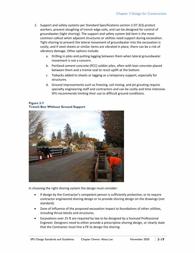
1. Trench Boxes are designed to protect workers, but they allow some excavation soil movement behind them. See Standard Specifications section 2-07.3(2). A trench box allows for quick and efficient excavations if there is not significant risk of damage associated with soil movement to adjacent utilities that are above and close to the trench (Figure 3-7 depicts a trench box without surrounding ground support). Some variations for worker protection include:
a. Sloping trench sides back. b. Jacks with or without plates behind them.
Chapter 3 Design for Construction
SPU Design Standards and Guidelines Chapter Owner: Alissa Lee November 2020 3-19
2. Support and safety systems per Standard Specifications section 2-07.3(3) protect workers, prevent sloughing of trench edge soils, and can be designed for control of groundwater (tight shoring). The support and safety system bid item is the most common callout when adjacent structures or utilities need support during excavation. Tight shoring to prevent the lateral movement of groundwater into the excavation is costly, and if steel sheets or similar items are vibrated in place, there can be a risk of vibratory damage. Other options include:
a. Drilling in piles and putting lagging between them when lateral groundwater movement is not a concern.
b. Portland cement concrete (PCC) soldier piles, often with lean concrete placed between them and a tremie seal to resist uplift at the bottom.
c. Tiebacks added to sheets or lagging as a temporary support, especially for structures.
d. Ground improvements such as freezing, soil mixing, and jet grouting require specialty engineering staff and contractors and can be costly and time intensive. SPU recommends limiting their use to difficult ground conditions.
Figure 3-7 Trench Box Without Ground Support
In choosing the right shoring system the design must consider:
• If design by the Contractor’s competent person is sufficiently protective, or to require contractor engineered shoring design or to provide shoring design on the drawings (not standard).
• Zone of Influence of the proposed excavation impact to foundations of other utilities, including thrust blocks and structures.
• Excavations over 25 ft are required by law to be designed by a licensed Professional Engineer. Designers need to either provide a prescriptive shoring design, or clearly state that the Contractor must hire a PE to design the shoring.

Chapter 3 Design for Construction
3-20 SPU Design Standards and Guidelines Chapter Owner: Alissa Lee November 2020
• Support of utilities through shoring or crossing excavations and whether a separate utility support plan submittal is required. Figures 3-8 and 3-9 depict examples of utility supports.
• When groundwater is expected in an excavation the design should contain enough information for the Contractor to effectively quantify the work in the bid and an engineered design of a dewatering system, if needed. The Contract should include: − Any records of groundwater depth − Estimated groundwater inflow rates − Any seasonal or tidal variations in groundwater depths − Discharge locations and any limitation on discharge rates − Permits and/or anticipated permit restrictions
Figure 3-8 Water Main Supported with Nylon Strap
Figure 3-9 Beam and Strap Utility Support
3.9.3 Utility Locates, Relocations, Protection, and Coordination During Construction
Relocation of most utilities has a long lead time. Many systems may be expensive and in some cases cannot be moved. Consider whether the project can be completed by working around the utility. Remember that the utility to be moved will need time to develop plans, obtain permits, and do the construction.
When looking at basemaps, the locational accuracy of various utilities may vary. Note any question marks shown on plans, profiles, or basemap research. Note that locations of bored installations cannot be as tightly defined as trench-installed utilities, even when good record drawings are available.

Chapter 3 Design for Construction
SPU Design Standards and Guidelines Chapter Owner: Alissa Lee November 2020 3-21
Locate wires are installed using one of three methods:
1. Direct buried wires 2. Wires in conduit 3. Wires in conduit duct bank encased in concrete
In addition, miscellaneous information on various buried utilities includes:
• SCL. When excavating next to SCL high voltage, SCL requires an SCL safety observer. See Standard Specifications section 1-05.2(2).
• Communication. Damaged fiber optics can be very expensive to repair. • Puget Sound Energy (PSE). In many cases PSE requires a safety observer when
excavating near PSE lines. PSE is replacing its old iron lines with high-density polyethylene (HDPE) and other plastic lines often installed by directional drilling. Whenever possible identify abandoned gas lines.
• Enwave (Seattle Steam). These lines often have an exterior insulation coating of asbestos.
• Olympic Pipeline. Try to avoid excavation adjacent to an Olympic Pipeline because future relocation is difficult. If digging nearby one of these pipelines, an Olympic Pipeline safety observer is required.
Tip: Consider working with utilities to have them moved prior to general contract work. They can become critical path obstacles and lead to delays and COs.
3.9.3.1 When to Pothole?
In a perfect world, all utilities will be located during the design phase and there will be no need for the Contractor to pothole existing utilities. In the current schedule-driven world, the design team may need to shift some of this responsibility to the Contractor.
When any crossing or potential conflict is critical information (project stopping vs. project adjusting), potholing responsibility should not wait until the Contractor is on board.
The type of work that usually requires potholing is trenchless, particularly directional drilling. In this case, it may be best to make any potholing incidental to the work. Whether incidental or separately bid and paid, potholing expectations of the Contractor need to be clear and enforceable.
Figure 3-10 is an example of work that should have included potholing to prevent damage to the conduit.

Chapter 3 Design for Construction
3-22 SPU Design Standards and Guidelines Chapter Owner: Alissa Lee November 2020
Figure 3-10 Damage and Danger to Conduit
Tips: For gravity fed systems where there is limited flexibility in the elevation of improvements, direct the Contractor to pothole early in the project. Early knowledge of conflicts allows designs to be modified if needed without adversely impacting the schedule.
Consider restoration cost before requesting potholing in concrete roadways. Even a 1-ft square hole for potholing may trigger the SDOT pavement restoration policy for panel replacement. In some cases, potholing for multiple utilities can be clustered into a limited number of panels.
3.9.4 Settlement Monitoring The designers should consider including settlement monitoring whenever projects require excavation deeper than adjacent utilities or other structures that might be at risk because of construction activities. Cast iron water mains and walls within the zone of influence are two high-risk items.
See section 5.10.1.2 of DSG Chapter 5, Water Infrastructure for monitoring settlement of water mains. Settlement monitoring of water mains along with surface monitoring can sometimes provide good information for analysis of potential impacts to SPU’s deeper pipe assets, like sewers. When settlement contours indicate a need to evaluate potential damage to the sewer system, the most common method is to is to install closed-circuit television (CCTV) to monitor the pipes before and after construction for evaluation and documentation of any damage.
Project teams should evaluate settlement risks to adjacent structures and consider requiring settlement monitoring when the work is in the influence zone of a foundation, soils are liquefiable, or other indicators of risk are present. In addition to clear and realistic measurement requirements, it is important to clearly identify settlement limits and consequences. Consider adding geotechnical expertise on settlement to the project team and developing a conceptual settlement monitoring plan. For tunneling projects, always include settlement monitoring in the design scope.

Chapter 3 Design for Construction
SPU Design Standards and Guidelines Chapter Owner: Alissa Lee November 2020 3-23
During construction, it is important to clearly identify who on the project team will be responsible for review of settlement reports from the Contractor, which could be received daily. Do not assume this is the responsibility of the resident engineer.
Tip: When requiring settlement monitoring, it is important to clearly define an area or points to be monitored.
3.9.5 Charged Water Mains For construction around water mains, consider how to protect the existing in-service water system, even if it will be abandoned later. On the plans clearly identify all water mains, including materials and joint type that will have adjacent excavation and include large laterals to services and fire hydrants since a break anywhere in the system can be catastrophic. Basemaps will not show thrust blocks but should be assumed at bends and tees. Define in the contract:
• The extent of the trench safety and support system (as opposed to a trench safety system only) to support the water main during excavation.
• The extent of saw cutting and removal of concrete pavement over a cast iron water main. Saw cutting and moving sections better protects from impact and vibration instead of allowing pavement breaking directly over a lead joint pipeline.
• Consider restricting the length of open excavation within the zone of influence of a charged water main to expose only one pipe joint at a time.
• Method for crossing under a water main. That is, stay as perpendicular as possible and restrict the length of water main needing support through an excavation.
• Require the Contractor to submit a support plan before excavating below the water main.
For information on thrust blocks, see sections 5.6.3.6C, 5.6.3.9, and 5.6.3.10 of DSG Chapter 5, Water Infrastructure.
Tip: Loss of soil support to a thrust block can result in pipe separation and system failure.
3.9.6 Asbestos Pipe Abandonment and Disposal Identify any asbestos pipe on the drawings and plan for disposal. Small sections of asbestos can be left in the trench and buried in the backfill. Working with asbestos pipe requires special training and equipment. See SPU policy on Asbestos Handling.
3.9.7 Confined Spaces The Contractor is responsible for their own safety program on confined spaces and SPU personnel entering a confined space need to be aware of the risks and SPU policy on confined space entry, but also follow the Contractor’s safety plan.

Chapter 3 Design for Construction
3-24 SPU Design Standards and Guidelines Chapter Owner: Alissa Lee November 2020
There are two areas of special concern where extra planning and coordination is typically required when Contractors need to enter existing SPU confined spaces:
• Work in an existing pipeline or tunnel where any rescue plan is particularly difficult or hazardous. This can include consultations with the fire department.
• Work that requires SPU to lock out and tag out equipment to increase safety requires coordination and a communication plan to maintain the integrity of the lock out.
Tip: Do not rely on standard monitoring records. Characterize the system; look for valves, pumps, and sources; and consider the risk as if lives are at stake.
3.10 ABOVE-GROUND CONSIDERATIONS Above-ground considerations include:
• Poles and guy wires • Overhead wiring • Buildings • Walls and bridges • Railroads • Hillsides
Trees are not included in this section; see DSG section 3.7.2, TVSPP. Streets are also not included in this section; see DSG section 3.16, Traffic and Public Access.
3.10.1 Poles and Guy Wires Keep planned excavations away from poles and guy wires to the extent practicable. Guy wires indicate an end pole or turning pole. Some guy wires are less obvious when connected to a pole or building. Strain poles likely have a streetlamp connected to them, but they can also have traffic signal or trolley wires. Strain poles, turning, and end poles are much less able to withstand loss of soil support than a pole on a straight wire run that is designed to only support for sag (similar to thrust blocks on water mains). Depths of pole foundations are not typically shown on basemaps. When planning excavation that could undermine a pole’s foundation, check the record drawings for foundation details and coordinate with the pole owner, most often SCL, SDOT, or the King County Metro Transit Department (Metro). Mitigating impacts to poles and guy wires can be a significant portion of project management.
Tip: Joint use of poles means that, when moving a pole, first SCL installs the new poles and another crew transfers wires. This is followed by the other utilities, one by one. Each pole has a designated utility that is the last off and responsible for removing the old pole, frequently CenturyLink. Provisions for removal may be necessary. Assume that this process is time intensive; coordination must start before the Contract is signed.
Chapter 3 Design for Construction
SPU Design Standards and Guidelines Chapter Owner: Alissa Lee November 2020 3-25
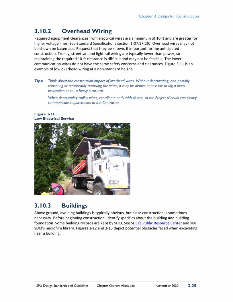
3.10.2 Overhead Wiring Required equipment clearances from electrical wires are a minimum of 10 ft and are greater for higher voltage lines. See Standard Specifications section 1-07.17(2)C. Overhead wires may not be shown on basemaps. Request that they be shown, if important for the anticipated construction. Trolley, streetcar, and light rail wiring are typically lower than power, so maintaining the required 10-ft clearance is difficult and may not be feasible. The lower communication wires do not have the same safety concerns and clearances. Figure 3-11 is an example of low overhead wiring at a non-standard height.
Tips: Think about the construction impact of overhead wires. Without deactivating, and possibly relocating or temporarily removing the wires, it may be almost impossible to dig a deep excavation or set a heavy structure.
When deactivating trolley wires, coordinate early with Metro, so the Project Manual can clearly communicate requirements to the Contractor.
Figure 3-11 Low Electrical Service
3.10.3 Buildings Above ground, avoiding buildings is typically obvious, but close construction is sometimes necessary. Before beginning construction, identify specifics about the building and building foundation. Some building records are kept by SDCI. See SDCI’s Public Resource Center and see SDCI’s microfilm library. Figures 3-12 and 3-13 depict potential obstacles faced when excavating near a building.

Chapter 3 Design for Construction
3-26 SPU Design Standards and Guidelines Chapter Owner: Alissa Lee November 2020
Figure 3-12 Excavation Next to a Building
Figure 3-13 Trench Side View
3.10.4 Walls and Bridges When considering excavations near walls and bridges, it is important to review the construction record drawings and understand all potential effects. Basemaps may not show all foundations and will not give overhead clearances, unless requested. Always ask for survey and basemap research to show all critical information needed for design and construction. Also, assure tiebacks or foundations are not compromised. Structural calculations for SDOT-owned structures are available and may be helpful in analyzing risk to major structures from adjacent excavations.
Reviews by the structure owner can add complexity to the review process and special requirements and permit conditions should be expected. Incorporate all requirements and conditions into the drawings and Project Manual.
Tip: Excavators working under a structure are constrained and low head equipment may be needed. Recognize that the Contractor’s special equipment needs may have long lead times.
3.10.5 Railroads Work around railroads includes heavy rail, light rail, and streetcars. There are a variety of rules permits and ownership (franchise vs. rail property) that can complicate project around rails. The approach for clearances, safety procedures, and special permit conditions should be incorporated into the drawings and Project Manual. Identify heavy rail rules and include extra review time in the schedule if the project is within 30 ft of the center of railroads. For light rail, streetcar, and trolley bus disruptions, see Standard Specifications section 1-07.28.
3.10.6 Hillsides A geotechnical engineer should evaluate construction in the vicinity of steep hillsides on a case-by-case basis, as recommendations are site-specific. See DSG section 3.15, Geotechnical Services.
For additional information, refer to Standard Specifications section 25.09.
Tip: Groundwater is a common issue during construction on hillsides. Check subsurface information when designing in the vicinity of steep-slope areas to evaluate groundwater conditions.
Chapter 3 Design for Construction
SPU Design Standards and Guidelines Chapter Owner: Alissa Lee November 2020 3-27
3.11 SEWER AND DRAINAGE BYPASSES When working on wastewater pipes, sewage cannot be turned off like drinking water supply. A contractor can request a customer to reduce sewage use for no longer than eight hours. Rain will change both the sewer flow (especially in combined sewers) and drainage flow, with the potential to jeopardize the work area and the safety of any workers in an excavation. Sewer backups, flooding, and property damage are not acceptable. During design, project teams should identify these backup and flooding risks and measures to minimize them.
A sewer bypass plan is necessary for all projects where a gravity mainline will be taken out of service. Depending on the project, lateral bypass (sewer laterals, catch basin (CB) connections, or other lateral connections) will also be required.
The design engineer should identify at least one feasible sewer bypass scenario during design. If there is only one acceptable scenario, the design engineer should develop a conceptual bypass plan for inclusion in the bid documents. A conceptual bypass plan should include requirements that pipes and pumps be sized to convey the expected and maximum flow during the construction period. Any project bypassing constraints or requirements should be clearly noted on the conceptual bypass plan. Specific equipment callouts are not typically part of the conceptual bypass plan but should be in the Contractor’s submitted bypass plan, along with expected durations and locations.
For a drainage-only system, identify flooding risks in relationship to the planned duration of construction and both seasonal and specific weather forecasts. Projects with a short duration may not require a pumped bypass if there is no base flow. Some construction activities may allow for emergency restoration of gravity flow when there is unexpected rainfall. When pumping is needed, ensure that the hydraulic grade line is 3 ft below the lowest gravity service line. In addition, requirements for a sewer bypass apply to a drainage-only system.
The design engineer should provide both a low-flow and high-flow estimate for the Contractor in the bid documents. See Standard Specifications section 7-17.3(2)I.
In general, the Contractor must: • Submit a bypass plan. • Provide pumping system to bypass low flows. • Provide a back up to the pumping system. • Have a plan in case high flows are encountered. • Provide appropriate fittings and pipe systems. If a leak occurs in the system, the
Contractor must replace or repair the system and test it with clean water using a standing head method.
For guidance on completing projects in creeks and streams, refer to DSG section 3.13.2. The following are SPU minimum standards and guidance for bypassing flows:
• Continuous bypass operation requires clear responsibility for operation and maintenance of the bypass. See Standard Specifications section 7-17.3(2)I2.
• Bypass to control the risk of sewer backups, flooding, property damage, and environmental damage.
• Require a high-flow emergency plan.

Chapter 3 Design for Construction
3-28 SPU Design Standards and Guidelines Chapter Owner: Alissa Lee November 2020
• Use the approved City-Wide Sewer Model to determine the low-flow and high-flow values for the sewer system. Consult with the Sewer Rehabilitation Group.
• The pump and bypass conduit must be of adequate size and capacity to handle the flow. The effluent level in the bypass pumping MH must not cause backups to any adjacent buildings or facilities. In most cases, the effluent level must not be allowed to rise more than 1 ft above the crown of the incoming sewer pipe. Work must follow Standard Specifications section 7-17.3(2)I.
Tips: Supporting and maintaining a closed-pipe system while building a structure around it can be cheaper and easier. This type of MH is called a saddle MH and it can be cheaper and easier to construct than a bypass. After the structure is installed, the channel is built to conform to the existing pipe and then the pipe is opened at the top.
When timing construction for low flows, always have a fallback plan in case of rain. Remember that, although August is associated with low-flow conditions, it typically includes at least one large thunderstorm.
Check for potential roadway flooding for the period that a CB will be out of service. It is generally cheaper and preferable to use the roadway to move stormwater to the next downstream CB. If the structure is at a closed contour, have a plan to bypass CBs as well.
3.12 MAINTAIN WATER SERVICE For each project that has a water shut down, consider how to keep SPU customers receiving water. Clearly present timing restrictions, customer service expectations, and requirements for coordinating with SPU crews for water shutdowns, reinstatements, and service connections in the contract documents.
3.12.1 Construction Sequencing to Minimize Service Disruptions to Water Customers
Basic steps for determining water service impacts when replacing a section of water main are:
1. Request SPU Operations assistance in determining the limits of the shutdown and the need for testing existing valves to ensure they are working properly.
2. Work with SPU Customer Service for a service list and restrictions on outages and with SPU Operations staff to determine whether a temporary service is required. If so, see DSG section 3.12.2, Temporary Services. Example questions to consider when determining the need for temporary services:
a. Are there critical customers (hospitals, kidney dialysis) without a separate feed? b. Are there hotels, restaurants, or laboratories that would be shut down without
water? c. Will the service transfers or connections require more than an eight-hour
shutdown? d. How many shut offs would there be at a single property (no more than three
allowed)?

Chapter 3 Design for Construction
SPU Design Standards and Guidelines Chapter Owner: Alissa Lee November 2020 3-29
e. Does the Fire Department require a hydrant be kept in service? Is a working hydrant within 350 ft of every building?
3. Plan the sequencing of the service disruption: a. Identify how and where to dewater the existing pipe (obtain permits, if
required). b. Construct new water main and valves. c. Pressure test new pipes and valves. d. Water quality test new pipes and valves (minimum of three days for each test). e. Schedule crews to make connection to live water main. See Standard Plan 300. f. Schedule crews to transfer services from old water main to new main and
replace services identified as needing replacement (for example, plastic and galvanized pipe).
g. Abandon, or abandon and fill, the old pipe. 4. If there is only one feasible solution, add an allowable sequencing plan to the drawing
and specifications.
A water outage map has been created to display planned and emergency water outages and impact areas. A future version may include tool enhancements that could be used during preliminary screening and planning.
Tips: When the valves are a long way apart, consider adding additional valves and blocking prior to water main removal or cut and cap. Talk to your supervisor and Operations.
Water in a pipe that is shut down for more than 14 days needs to be disposed of and the pipe will need disinfection. Plan sequencing to avoid a shutdown of this length.
3.12.2 Temporary Services New water main alignments should be designed parallel to the existing main with an offset to keep the existing main in service until services can be transferred to the new main. Temporary water mains are costly and should be avoided if possible.
If a temporary water main or service is required, consider the following items:
• Any critical customers in any of the shutdown areas to setup the temporary services (especially hospitals, retirement homes, and home kidney dialysis patients).
• A special plan is needed to maintain services to critical customers. • Size of the largest fire service (detector check meter). The temporary service will have to
be at least that size. • The number and type of services in the affected zone. • Customer water usage and the amount of water needed in the temporary main to
support regular domestic use. • The operating pressure in the area and whether the temporary service will differ. A
difference might change the size of the temporary line or where connections are made. • Buildings with fire service connected or that are very close to each other. If so, consider
increasing the main size to accommodate both fire services together.

Chapter 3 Design for Construction
3-30 SPU Design Standards and Guidelines Chapter Owner: Alissa Lee November 2020
• The services that are for businesses that need water to operate and whether shutdown impacts can be minimized.
• The location that the temporary main or service will be connected. • Whether the connection points for a temporary service affect vehicle traffic. If so, the
traffic impacts will need to be minimized as much as possible to satisfy SDOT’s requirements.
• Whether the temporary main or service affect sidewalk use? If so, can Americans with Disabilities Act (ADA) access requirements be maintained? If not, pedestrian traffic will have to be rerouted and this will require approval from SDOT.
• Whether the temporary main or service affects a bike lane. If so, bike traffic may need to be rerouted to satisfy SDOT requirements.
• Whether service rehabilitation is needed before connecting the existing service to the temporary water main. For example, cast iron laterals with tie-rods may need to be upgraded to ductile iron before connection.
• The likelihood of vandalism. Avoid using copper pipe where it will be above grade and accessible to the public.
• Whether the temporary water main will be in use in the winter? If so, this will affect the choice between above- or below-grade installation or may require freeze protection, affecting the overall cost of the work.
• Consider whether the Contractor should build, protect, and maintain the temporary water main or whether SPU Operations should install both the temporary water main and services. Discuss with SPU Operations, especially if the temporary water main is larger than 2 inches, longer than 100 ft, or complex.
3.13 WORKING IN A CREEK OR STREAM Designing work in creeks and streams can be a special challenge because it often combines art, hard engineering, and biology.
3.13.1 Fish and Permits It is often necessary to capture and relocate fish either at the beginning of a project or just prior to, or in conjunction with, stream dewatering. Prior to capture and relocation, some sort of fish barrier, often in the form of nets, needs to be installed at the upstream and downstream end of the project.
Tip: Because of regulatory concerns, it may be prudent to include provisions in the Contract for SPU staff or other experts to do the fish relocation.
Work in streams always requires permit(s). The permits generally have a defined fish window (that is, a date-limited time when bypassing and in-stream work is allowed). Obtain the permits required for in-stream work prior to bidding and make meeting the fish window a clear contract requirement. Figure 3-14 shows fish removal occurring in conjunction with bypassing.

Chapter 3 Design for Construction
SPU Design Standards and Guidelines Chapter Owner: Alissa Lee November 2020 3-31
Figure 3-14 Fish Removal in Conjunction with Bypass
3.13.2 Stream Bypass The Contract should provide the Contractor with clear requirements for estimated flows and pump capacity. The Contract should also draft bypass line routing. In addition, the Contract should be designed and specified to ensure that if a storm occurs and the bypass system is overwhelmed, the overflow will not significantly damage the project under construction, or surrounding properties. Figure 3-15 illustrates stream bypass operation.
Figure 3-15 Stream Bypass Intake
Tip: Many of Seattle streams are at or near the water table. For any bypass longer than about 50 ft, consider including intermediate pumping (and possibly discharge) locations.

Chapter 3 Design for Construction
3-32 SPU Design Standards and Guidelines Chapter Owner: Alissa Lee November 2020
3.13.3 The Art of Stream Structure Placement Stream remediation projects are often designed to look like a natural stream. Some of the material most often used includes boulders and other finer sized aggregates; logs, logs with root wads, and living plants. These materials have non-uniform dimensions. Placing rocks to make a weir and plunge pools, or a log to force flow beneath it to create a pool can only be shown in basic concept on the plans. The actual details of placement of the materials may require an outside expert to be on-site during their installation. The consultant for this must be chosen with care. They need to be able to get it right the first time to not adversely impact the Contractor’s production.
3.13.4 Access Considerations Many Seattle streams have limited access for some or all of the following reasons:
• In-stream or adjacent private property • Located in steep narrow channels • Property owner or permits limiting the type or size of equipment allowed along some
sections of the stream
Figure 3-16 depicts an example of access limitations that may need to be considered.
Tip: Be sure the project is constructible, given access or equipment limitations. Clearly state these limitations in the contract documents.
Figure 3-16 Hand-carried Logs for Stream Structure
3.13.5 Measure and Payment As a rule, having a measured or survey cubic yard (CY) bid item for common or stream bed excavation is not practical. In order to stabilize slopes the Contractor may need to install boulders or other features immediately after excavation; the excavations are often an irregular size that is difficult to measure; and having a survey crew on-site for multiple days to cross section excavations is expensive. Consider making excavation lump sum, or payable by the truck loaded CY.

Chapter 3 Design for Construction
SPU Design Standards and Guidelines Chapter Owner: Alissa Lee November 2020 3-33
3.14 WORKING IN THE WATERSHED Since both the Cedar and Tolt Watersheds (Figures 3-17 and 3-18) provide drinking water supply to Seattle and its ratepayers, working in the watershed requires extra consideration not often thought about for in-City work. Seek direction from watershed staff early. Provisions that apply from the Cedar River and South Fork Tolt Watersheds Water Quality and Protection Regulations should be incorporated into the contract.
Figure 3-17 Conduit Installation on Tolt Dam Lake
Figure 3-18 In-Water Barge Operations on Chester Morse
When working within a watershed, consider the following:
• Security plan development and access through the Cedar River Watershed Access Permit System (CAPS) process or the SPU Security Process. The process will depend on which watershed the project is in and where in that watershed the project is taking place (e.g., projects in Landsburg follow the SPU’s Security Process, but projects upstream of Landsburg follow the CAPS process).
• Lack of utilities that would normally be available for in-City construction, such as power, communications, water, sewer, and drainage. Projects in the watershed should account for temporary utilities, such as generators, radios, water coolers, and portable toilets.
• Longer haul routes and supply chains: − May need custom PCC requirements such as retarders and relaxation of American
Concrete Institute (ACI) standards if it takes more than one hour to get to the job site.
− Consider alternatives to cast in place PCC, such as pre-cast elements. − A large staging area can help mitigate the longer haul routes for some durable items
that can be stockpiled on-site. − Deliveries will require vehicle inspections and possible decontamination procedures.
• The sanitary and spill prevention and cleanup requirements will likely be enhanced via SPU’s water quality and protection regulations. This is especially true for work near the water.

Chapter 3 Design for Construction
3-34 SPU Design Standards and Guidelines Chapter Owner: Alissa Lee November 2020
• Prevention of Aquatic Nuisance Species (SPU water quality requirements) is a policy for any work conducted on any surface waters (including rivers and streams) within the watershed. Contact SPU Water Quality Lab for latest procedure and documentation requirements.
• There may be a greater likelihood of encountering an archeological site. Within the Cedar River Municipal Watershed, projects will most likely encounter logging camp debris, old garbage dumps, railroad ties, and dilapidated structures. Native people archaeological sites have been extensively documented. Contact SPU’s Public and Cultural Programs Manager to obtain guidance and requirements. Depending on the activity, the project team may need to obtain approval from local tribes via SPU’s Public and Cultural Programs Manager.
• Red flag or high wildfire risks may shut down construction. Contact SPU Watershed Protection for the latest SPU Fire Resource Manual and its requirements.
• Communication plans for remote construction should be developed. Many areas of the watershed have no phones or cell phone reception. Watershed staff can provide temporary radios and call identifications to SPU and Contractor staff.
• Emergency plans must consider long travel times. Slow travel along curved dirt/gravel roads can add significant time to the already lengthy distance to a hospital.
• Weather should be monitored several times a day due to the potential for rapidly changing weather at elevation, especially in the fall and winter. Clothing, layers, food, and water should be available for the construction team.
• Contracts should take into consideration the effects on protected species and incorporate all protective permit requirements. Consider including environmental and animal specialists on the construction team.
• Other cost and schedule risks that should be considered with working in the watershed: − Tribal hunting season − Watershed operations (roads, trees, fish, and wildlife) − Fish window − In-water work and lake levels associated with water supply and demand − Permitting through County, State, and Federal agencies
3.15 GEOTECHNICAL SERVICES The geotechnical engineer’s characterization of the subsurface conditions and materials is critical during project initiation and options analysis phases. To this end, the geotechnical engineer evaluates available subsurface information and performs additional subsurface explorations and laboratory testing when needed.
Tips: SPU highly recommends that the geotechnical engineer-of-record project responsibilities be assigned to the geotechnical engineer during initiation and options analysis and remain engaged in that role for the duration of the project.
The Stormwater Manual contains minimum requirements for subsurface investigation that may apply to each project. If it does apply, make sure that the scope of geotechnical services can

Chapter 3 Design for Construction
SPU Design Standards and Guidelines Chapter Owner: Alissa Lee November 2020 3-35
also be used to satisfy stormwater code regulations and permitting requirements. Especially for investigation of infiltration potential, check for requirements affecting location of testing and formats for reporting.
3.15.1 Provide Available Project Information Any project information is useful to the geotechnical engineer to anticipate the project’s geotechnical needs.
Tip: Provide all available proposed project details, preliminary or not (e.g., structure types, depths/elevations, plans, and loads), so the geotechnical engineer can anticipate design considerations, required analyses, and the best methods to obtain any required supplemental data.
3.15.2 Available Subsurface Information Available existing information may allow the geotechnical engineer to characterize the subsurface without need for additional explorations. Typically, information obtained within a horizontal distance of 150 ft and which extends to at least 10 ft below the minimum design elevation of the proposed structural components may be applicable to a project site. The geotechnical engineer may require additional explorations and laboratory tests to characterize the site’s subsurface materials and conditions.
Tip: Adequate characterization of the site helps designers to design elements (e.g., foundations, earth-retaining systems, and subsurface improvement/stabilization) with adequate capacity for the project’s geotechnical demands (e.g., bearing capacities, lateral earth pressures, uplift forces, and groundwater conditions) and contractors with construction methods and estimates (e.g., shoring systems, dewatering systems, excavation/fill quantities, and material disposal). Note that anticipated subsurface conditions/materials should be confirmed during construction, to allow significant changes to be incorporated into design elements/construction methods (e.g., over excavation and imported backfill may be required to provide a competent subgrade, and a more robust dewatering system may need to be implemented to maintain a dry excavation).
3.15.3 Additional Subsurface Information The number, depth, and type of additional subsurface explorations are specified by the geotechnical engineer to obtain information to develop geotechnical design recommendations, and they vary based on specific project requirements. If there are any indications or existing environmental issues associated with a project or site, it is advisable to have an Environmental Site Assessment (Phase I) performed during the project initiation and options analysis phases by an environmental engineer. If the Phase I findings suggest a sampling and testing program (Phase II) be performed, SPU recommends that the environmental and geotechnical engineers collaborate to carry it out while performing geotechnical subsurface explorations.
Tip: Having a Phase I and II in place will not only allow contractors to estimate disposal quantities and costs but will enable delineation of extents of contamination during construction. Delineation and characterization will also allow the Contractor and SPU to develop appropriate safety plans.
Chapter 3 Design for Construction
3-36 SPU Design Standards and Guidelines Chapter Owner: Alissa Lee November 2020
3.15.3.1 Subsurface Exploration Methods Some subsurface exploration methods may be implemented quickly and require none to very little site disturbance (such as geophysical methods, cone penetration tests, and push-probes, in order of disturbance). Other methods generate spoils that may require disposal (such as hollow-stem, mud-rotary and roto-sonic drilling methods, and test pit excavations). The geotechnical engineer should determine which method will yield the data for the appropriate degree of characterization required for the project.
Tip: Subsurface explorations may require significant coordination and permits, so their associated resourced timeline for procurement should be factored into the project schedule. See DSG Chapter 2, Design for Permitting and Environmental Review for permitting information.
3.15.3.2 Groundwater Characterization and Infiltration Potential Groundwater monitoring wells should be installed at any proposed project sites that may be affected by the groundwater table elevation, whether during construction or for permanent design. Sites where determination of groundwater elevation is important include: sites with documented high groundwater or flooding; sites with complex groundwater regimes; sites with soil that may liquefy or soften; and/or sites where dewatering will be required to complete construction.
Tip: In addition to providing data to capture groundwater seasonal elevation changes, monitoring wells allow hydrogeologists to estimate preliminary dewatering volumes and permeability of materials to allow designers/contractors to design and permit dewatering (temporary) and groundwater control (permanent) systems where needed. Dewatering and disposal can be a major project cost. Sometimes, judiciously placed monitoring wells may also be used to assess the effectiveness of dewatering systems. Upon completion of a project or if impacted by construction, groundwater monitoring wells need to be decommissioned by a licensed driller per Ecology guidelines.
At project sites with proposed infiltration facilities, the geotechnical engineer should rely on infiltration test data to determine the infiltration characteristics of subsurface materials. Depending on the size and type of facility, a simple infiltration test, pilot infiltration test (PIT), large PIT, or deep underground injection control (UIC) infiltration test will need to be performed. Monitoring wells will be required for certain sizes and types of facilities.
Tip: Note that some geotechnical explorations and tests must be performed by a State of Washington licensed professional engineer, geologist, engineering geologist, or hydrogeologist, experienced in infiltration and groundwater testing and infiltration facility design. For further clarification, consult the Stormwater Manual.
3.15.4 Construction Support During the construction phase, the geotechnical engineer provides construction observation to confirm that the subsurface materials and conditions encountered during construction are consistent with the subsurface characterization used for the engineering recommendations and to verify that the geotechnical aspects of construction comply with the contract plans and specifications. Where projects have acquired an SDCI building permit, the geotechnical engineer

Chapter 3 Design for Construction
SPU Design Standards and Guidelines Chapter Owner: Alissa Lee November 2020 3-37
performs geotechnical special inspections during construction as the geotechnical engineer-of-record. Where projects have temporary or permanent components that fall under the jurisdiction of SDOT, the geotechnical engineer performs geotechnical inspections as delineated by the SDOT inspector.
Tip: The SPU resident engineer overseeing the project should rely on the geotechnical engineer’s confirmation of subsurface conditions and materials. Rely on the geotechnical engineer’s direction if conditions and/or materials encountered are different from anticipated and warranting changes to design or construction. Examples of such instances include deficient subgrade, differing groundwater elevations/conditions, obstructions (such as boulders or trees and roots), voids, and contamination.
3.16 TRAFFIC AND PUBLIC ACCESS Most projects in the ROW will require some sort of Traffic Control Plan (TCP). Do not assume that Standard Specifications section 1-07.23 alone will take care of site traffic and public access needs.
3.16.1 Work Sequence and Staging Consider how much of the site, road, and sidewalk can be closed at any given time. Also consider possible adverse impacts if work occurs on adjacent streets at the same time.
Tip: Consider changing road alignment whenever possible. An alignment shift has much less impact than a closure.
3.16.2 Traffic Control Plans Choose whether the TCP should be included with the plan sheets (mostly for larger or high impact projects) or whether having the Contractor responsible to submit to SDOT will be sufficient. When there are no SDOT requirements, have the Contractor submit a plan to the construction engineer only. The Project Manual should clearly identify requirements and elements of the plan that add costs.
Determine whether flagging will be needed; where traffic signals need to be overridden, uniformed police officers are required.
Detours. Unless permission is granted by SDOT, traffic on arterials cannot be detoured to non-arterials. Figure 3-19 is an example of a residential street closure.
Tips: If arterial to non-arterial detours would be the most cost effective for the Contractor, obtain permission before the project is advertised so that detour requirements are clear. The answer from SDOT in most cases will be no.

Chapter 3 Design for Construction
3-38 SPU Design Standards and Guidelines Chapter Owner: Alissa Lee November 2020
Figure 3-19 Residential Street Closure
Building access. Understand how building access will be impacted and ways to mitigate this impact, if necessary.
Driveways. Remember that when concrete driveways are being replaced, the property owner may not have access to the driveway for more than a week for removal, grading, forming, pouring, and cure time. For parking lots and some structures, determine whether there are multiple entrances. If so, consider phasing access replacement as needed.
Pedestrians. Consider how children and other pedestrians will get through the construction site, and any other public safety considerations. One solution is a temporary pedestrian bridge (Figure 3-20).
Figure 3-20 Temporary Pedestrian Bridge

Chapter 3 Design for Construction
SPU Design Standards and Guidelines Chapter Owner: Alissa Lee November 2020 3-39
Bikes. Cyclists tend to ignore detour signs; consider bike riders’ safety in TCP requirements. It is difficult to detour bikes, avoid when possible.
Fire access. The design and project management team will need to work with the Seattle Fire Department to assure fire access.
Trolleys and street cars. The design and project management team will need to work with Metro and Sound Transit to assure public transportation impacts are mitigated. In many cases individual bus stops can be temporarily relocated or closed. In most cases Metro will allow temporary conversion of overhead electric trolleys to diesel buses only on weekends at the requesting party’s expense. The Project Manager will need to know when shutting down stops or lines are unavoidable for early coordination with Metro.
Solid waste pick up and deliveries. Know where solid waste will be picked up in each project. Determine whether the project is in an area where ongoing deliveries can be expected?
Tips: For solid waste, consider one or more of the following:
• Requiring concrete placement for alley approaches only on the day or two after pick-up, for locations where solid waste is picked up in an alley. Use high early strength concrete (HES).
• If solid waste vehicles cannot access their traditional pick-up location, have clear contractor requirements to bring all solid waste containers to a location where they can be picked up.
• Set up a communication requirement with Solid Waste in the contract.
3.16.3 Temporary Pavement In addition to removal of existing pavement and final pavement restoration, designers should plan for any significant duration temporary surfacing, including quantifying for bidding.
Possible temporary surfaces include:
• Crushed rock base may be possible for short durations in arterials and non-arterials where there is limited traffic or temporary pedestrian routes (Figure 3-21). Before using, consider: − Surface water flowing across it. Crushed rock cannot be used if significant volumes
of water are expected when rain is possible because the risk of erosion/silt-bearing water runoff from the construction site.
− The amount of traffic that will be traveling on the crushed rock. − The extent of the gravel. Although it might work for a CB connection, it likely will not
work for an entire lane.
• Cold Mix asphalt concrete (AC) has its place in areas with small patches, but compared to temporary hot mix, it has these limitations: − Needs to be maintained, as it shifts and spalls under traffic. − Can be tracked off site. In areas where there is pedestrian traffic, the City has paid
claims for carpet cleaning and other tracking issues. • Temp Hot Mix AC placed at one time greater than about 5 tons are cost comparable to
cold mix, but hot mix does not have the limitations noted above for cold mix. There are disposal costs for both mixes.

Chapter 3 Design for Construction
3-40 SPU Design Standards and Guidelines Chapter Owner: Alissa Lee November 2020
• Permanent base AC paving where the final AC pavement will have several layers can be cost effective to use some of the lower layers as a temporary driving surface.
• Signs and striping may be required for the temporary pavement. For arterial streets, coordinate with SDOT temporary striping to maintain traffic functions.
Figure 3-21 Temporary Crushed Rock Pavement
Tip: Understand how temporary pavement edges will tie into existing pavement and castings. In some cases, the best approach may be a hybrid of materials such as Permanent base AC with cold mix at the edges. Sometimes the decision is best made as a field adjustment. If a field adjustment is planned, discuss the bid items needed with the construction management supervisor on the project.
3.17 SITE RESTORATION Much of SPU work involves installing underground systems. The designer needs to be aware of restoration at the ground surface level, and account for it on the drawings and bid item list. The plans need to clearly define what final condition of all areas impacted by the work will look like.
In most cases, the primary stakeholders will be SDOT, adjacent property owners, and in some cases other agencies. In almost every case where there is some disturbance in the ROW, a SDOT Street Use Permit will be required. SDOT will require that restoration be done in accordance with the Street and Sidewalk Pavement Opening and Restoration Rule. It is up to the project team to determine whether SPU or the Contractor will obtain the permit. For a larger project, the project team will typically obtain the permit. For some smaller projects, such as spot water or sewer repairs, it may be more cost effective for the Contractor to obtain the permit.
As a rule, a project with an approved Street Use Permit will have a well-defined pavement restoration plan including a plan for restoration of signs and striping, signal loops, and any other SDOT assets. It should also include plans for soil amendment or soil import of disturbed areas, landscape restoration, and any disturbed irrigation systems and mailboxes.

Chapter 3 Design for Construction
SPU Design Standards and Guidelines Chapter Owner: Alissa Lee November 2020 3-41
If trees will need to be cut down and/or if pruning of trees would amount to greater than one third of the live foliage, notify SPU’s Landscape Asset Manager, SDCI, and SDOT, as appropriate. Consult with SPU’s Landscape Asset Manager for advising on vegetation and soil restoration at the construction site. See section 4.10 of DSG Chapter 4, General Design Considerations.
3.18 INSPECTION, TESTING, AND REJECTION CRITERIA
Refer to the Construction Engineering Inspector’s Quality Assurance Handbook for a checklist for inspecting some of the most common construction items like pipelines and pavement. For information on commissioning operable facilities, refer to Infrastructure Commissioning Guidelines.
For construction inspection of less common items or sequenced projects, it is important for the project team to establish expectations for inspection and quality assurance. Projects where SPU takes on some operational functions while contractor testing and commissioning are ongoing require more thought. With phased projects, consider:
• Clearly defining facility responsibility and ownership by phase. Once SPU takes on some operational functions, it becomes more difficult to hold the Contractor responsible for problems.
• Consider using multiple phases of liquidated damages. For example, one phase for substantially completing the bricks and mortar construction and another for SCADA completion and/or operational testing.
See each of the discipline chapters for inspection and testing criteria.
3.19 FINAL ACCEPTANCE PROCEDURES Final acceptance procedures vary with the complexity of the project. For operable projects, see Infrastructure Commissioning Guidelines. For most City projects, Standard Specifications section 1-05.11 describes substantial and physical completion.
Tip: For projects with multiple sites, granting acceptance at one site prior to the Contractor mobilizing to the next site is often desired. In these situations, there should be clear contract language defining the sequencing. The language should also provide enforcement if the requirement is not met. Possible enforcement actions include separate substantial and physical completions dates with associated liquidated damages and withholding payment for work completed at the second site until the first site has completed all tasks.
The following sections summarize some typical project types.

Chapter 3 Design for Construction
3-42 SPU Design Standards and Guidelines Chapter Owner: Alissa Lee November 2020
3.19.1 Sewer Lining Projects The resident engineer approves each section. Approval requires successful pressure test, CCTV, and physical inspection. When there are specific design issues not clearly defined in the Contract the SPU Designer may be asked to determine whether a section is acceptable.
Tip: Overcutting the laterals after lining is a possible defect to watch for and can especially be a problem with polyvinyl chloride (PVC) tees (core taps and Inserta Tees® are common). When reviewing a plan for repair, it is helpful to identify at least one acceptable alternative (preferably trenchless).
3.19.2 Spot Sewer Repair Projects and New Drainage and Wastewater Pipes
See section 8.11.5 of DSG Chapter 8, Drainage and Wastewater Infrastructure for guidance on drainage and wastewater infrastructure.
• When there are not quality issues, or unique design issues, the resident engineer approves each section. Approval requires successful pressure test, CCTV, and physical inspection of various elements.
• When pressure testing by other than low pressure air method (infiltration test or exfiltration test) is required, it can be helpful to call that out on the drawings. If exfiltration testing is required due to proximity to an environmentally critical area, identify the critical area on the drawings. It may not be obvious.
• The SDOT Street Use Inspector approves the surface restoration. Until the SDOT Street Use Inspector closes the street use permit associated with the work, the project cannot be closed out. Note that sometimes for larger DWW projects the SPU design/project management team obtains the street use permit. In these cases, the SDOT part of the work will be closed out, either during the final inspection or when the Street Use permit is closed out.
• When there are specific design issues not clearly defined in the Contract the SPU Designer may determine whether a section is acceptable.
• If DWW lines are installed on another agency’s property (e.g., Seattle Parks Department), that other agency also needs to accept surface restorations.
3.19.3 Water Mains See section 5.11.3 of DSG Chapter 5, Water Infrastructure for guidance on water mains and other water infrastructure. The approval process for water mains requires extensive coordination with several units in Water Operations. See the Quality Assurance (QA) Inspectors Handbook for details. When designing water main work outside City limits, the design team should identify the local agencies that will be part of the approval process. It is best to get concurrence from those agencies on what the final restoration will address.
Chapter 3 Design for Construction
SPU Design Standards and Guidelines Chapter Owner: Alissa Lee November 2020 3-43
3.19.4 Bioretention and Biofiltration The acceptance procedure for CIP bioretention projects is not yet fully established. Inspector’s checklists and changes to Standard Specifications section 7-21 (bioretention) are under development. Check with the project supervisor and CMD on staffing for inspection of soils and landscaping.
Tip: For facilities that have UIC wells (deep ground water injection) be sure to include in the contract specifications clear requirements for flushing the cells prior to introducing water into the UIC wells. In addition, the facility needs to be designed so that the cell can be flushed. Connections to the well must be blocked, and there needs to be a gravity bypass or other ways for the cells to be pumped.

Chapter 3 Design for Construction
3-44 SPU Design Standards and Guidelines Chapter Owner: Alissa Lee November 2020
3.20 RESOURCES Removed for Security