chapter 3 - building form, core location and orientation...
TRANSCRIPT

Chapter3–BuildingForm,CoreLocation&OrientationBuildingEnergyEfficiencyTechnicalGuidelineforPassiveDesign (Draft1)
CK Tang

Page 2 of 35
Foreword This document is produced as part of Component 4, Building Sector Energy Efficiency Program
(BSEEP) by CK Tang ([email protected]) and Nic Chin ([email protected]).
The views expressed in this document, which has been produced without formal editing, are those
of the authors and do not necessarily reflect the views of neither JKR nor UNDP. Comments and
opinions from readers are encouraged and please email it to either [email protected] or
[email protected] or comment at our Facebook page: www.facebook.com/bseepc4
CK Tang
June 6, 2012

Page 3 of 35
TableofContents3. Building Form, Core Location and Orientation ............................................................................... 4
3.1 Objective ................................................................................................................................. 4
3.2 Key Recommendations: .......................................................................................................... 4
3.2.1 Location of AHU Room .................................................................................................... 4
3.3 Executive Summary ................................................................................................................. 5
3.4 Introduction ............................................................................................................................ 8
3.5 Methodology ........................................................................................................................... 8
3.6 Test Cases .............................................................................................................................. 12
3.7 Results ................................................................................................................................... 13
3.8 Appendix ............................................................................................................................... 20
1. Detailed Layout of Each Case Scenario ..................................................................................... 20
2. Weather Data ............................................................................................................................ 30
3. Building Model .......................................................................................................................... 31
4. HVAC Details of Case 0 .............................................................................................................. 31

Page 4 of 35
3. BuildingForm,CoreLocationandOrientation
3.1 ObjectiveTo provide an energy efficiency perspective guideline on the selection of building form, core location
and orientation.
3.2 KeyRecommendations:The selection of building form, core location and orientation for energy efficiency should have the
following priorities:
1. Provide Less Glazing Areas When Possible
Choose building form and core location that provides the least amount of glazing but
maintain the necessary aesthetical appeal of the building and view out.
2. Provide Excellent View Out
If the building is located in a place that will benefit from having views in all direction
(360°), selection of building with 360° view out is an acceptable option due to the
low ratio of BEI/View Out as compared to other building form, core location and
orientation.
3. Provide Good Orientation
Expose glazing to the North and South, but limit the exposure to East and West.
Finally, whenever possible place the core location with the following priorities:
i. East
ii. North‐East
iii. South‐East
iv. West
v. North‐West
vi. South‐West
vii. North
viii. South
Use this chapter as a general guide to pick the most energy efficient building form, core location and
orientation to fit the site, taking into consideration of the high priority of building aesthetical value
to the client and quality of view out.
3.2.1 LocationofAHURoomThe location of AHU room has a large influence in the fan energy consumption of a building. AHU
room should be located for the ductwork to distribute cold air evenly in the building within the
shortest route. The longer the distance of ductwork, the more energy will be used to distribute air‐
conditioned air to the space.
Tips: Place AHU room(s) for the shortest distance to distribute conditioned air evenly in the building.

Page 5 of 35
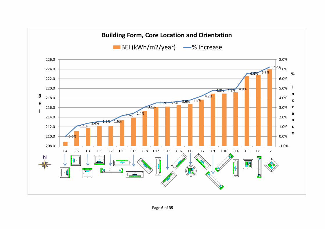
3.3 ExecutiveSummaryThis study showed that it is possible to save up to 7.2% energy based on the selection of building
form, core location and orientation. This study showed that the most significant reason for lower
building energy consumption in building is the glazing area. It was found that it was possible for
certain building form and core location to increase glazing area up to 48% as compared to building
with the least amount of glazing area, although all façade of actively air‐conditioned spaces (such as
office spaces) is assigned with glazing area of 70% window‐to‐wall ratio.
The second significant factor that impacts building energy efficiency is the ability to view out of the
building. The view out of building is computed in this study via the assumption of a person standing
in the middle of the building looking out through the external façade (internal partitions are
assumed to be invisible/transparent, while opaque external façade is opaque to compute the view
out in degree). A ratio of Building Energy Index (BEI) in kWh/m²‐year to View Out in degree was
computed to factor in the energy cost for view out of different building form, core location and
orientation. The ratio of BEI to View Out (degree) indicates the amount of energy used for each
degree of view out for each building. The lower the value, the less energy is used for each degree of
view out. The results from this study indicates that energy penalty of increasing view out, reduces as
view out is increased. In simple words – Yes, it increases energy consumption of the building with
more view out but not critically bad because the energy penalty for each degree of view out reduces
as view out increases.
The orientation of the building is also shown to have significant impact on the building energy
efficiency. The benefit of having good orientation allowed a higher glazing area and better view out
while reducing BEI of the building in certain cases.
The additional fan power due to toilet ventilation of center core is accounted for in this study, as
well as infiltration rate of building due to the wind speed and wind direction. The use of daylight
harvesting in office space up to 3.5 m depth from the building façade was also accounted in this
study. In addition, the potential daylight use of core spaces such as stair case, toilet and pantry were
also accounted if it is located on side instead of center core. In short, this study assumed that all the
good behavior of energy efficiency is practiced.
Page 6 of 35
0.0%
1.1%1.4% 1.6% 1.6%
2.2%2.4%
3.1%3.5% 3.5% 3.6% 3.8%
4.2%
4.8% 4.8% 4.9%
6.6% 6.7%
7.2%
‐1.0%
0.0%
1.0%
2.0%
3.0%
4.0%
5.0%
6.0%
7.0%
8.0%
208.0
210.0
212.0
214.0
216.0
218.0
220.0
222.0
224.0
226.0
C4 C6 C3 C5 C7 C11 C13 C18 C12 C15 C16 C0 C17 C9 C10 C14 C1 C8 C2
%
I
n
c
r
e
a
s
e
B
E
I
Building Form, Core Location and Orientation
BEI (kWh/m2/year) % Increase
Page 7 of 35
0%
10%
20%
30%
40%
50%
60%
0.00
0.10
0.20
0.30
0.40
0.50
0.60
0.70
0.80
0.90
1.00
C0 C1 C2 C7 C9 C10 C8 C4 C6 C3 C5 C11 C13 C18 C12 C15 C16 C17 C14
% Reduction
Ratio BEI/V
iew Out (degree)
Ratio of BEI/View Out
Ratio of BEI/View Out % Increase

Page 8 of 35
3.4 IntroductionThe result of any study on building form, core location and orientation can be easily tweaked to
reflect preference of one form over another rather easily by the assumptions made. Therefore, the
assumptions made in this chapter have to be clearly specified and transparent. In general, this study
assumed that all good building design practices are implemented to a reasonably well manner. This
includes daylight harvesting where feasible and natural ventilation where feasible as well.
This chapter attempts to find an optimum balance of the benefit of daylight harvesting in office
spaces versus having a “buffer zone” of non‐air‐conditioned space to keep solar and conduction heat
gain away from air‐conditioned office spaces. Spaces such as pantry areas are assumed to be air‐
conditioned if it is located without access to external windows and naturally ventilated when it has
an external window. In addition, it is also assumed that toilets located in the middle of the building
requires mechanical ventilation to provide 10 air‐change per hour (ach) while toilet located with
external windows was modeled without mechanical ventilation. Naturally ventilation was modeled
instead for toilets with external window.
It is also observed in many buildings that daylight harvesting is a fairly common practice for fire
escape staircases, pantries and toilet located with external windows and it is modeled as such for
this study. However, if these spaces are located away from the façade, the electrical lights for these
spaces are assumed to be switched on during occupancy, while fire escape staircase lights are on all
the time.
3.5 MethodologyA medium rise building of 17 floors is assumed for this study. The floor to floor height is assumed to
be 4 meter. The floor areas are as described in the table provided below.
No Descriptions Floor Area Units Ventilation Concept
1 Office Floor Area 1650 m2/floor AC
2 Lift Lobby/Walkway 170 m2/floor AC
3 3 no AHU rooms 100 m2/floor AC
4 4 no lift shafts 165 m2/floor NV
5 Pantry 22 m2/floorNV if located with external façade. AC otherwise.
6 2 fire staircases 72 m2/floor NV
7 Toilets 80 m2/floorNV if located with external façade. 10 ach otherwise.
Total Area per Floor 2259 m2/floor
No of Floors 17 floors
Total Building GFA 38,403 m2
For each building form, shape and orientation, the air‐conditioning system will be sized for the peak
design cooling load. Thereafter dynamic energy simulation of 1 full year was conducted to provide
the annual energy consumption of the building for each case study.

Page 9 of 35
These assumptions were made in this study to generate a comparison between building forms:
No Descriptions Location: Not Connected to any External Wall.
Location: Connected with an External Wall
1 Toilet Ventilation Strategy
Mechanically ventilated for 10 ach as exhaust air. Fan Static Pressure of 2” w.g. (500 Pa) assumed. Combined fan, motor and belt (total) efficiency of 50% assumed. Fan operates during occupancy hours of 9am to 6pm.
100% Natural Ventilation. Window area assumed to be 10% of floor area. Only 50% window area is open for ventilation.
2 Toilet Lighting Strategy
100% electrical lights at 10W/m², switched on during occupancy hours. Occupancy sensor is assumed to be installed. It is assumed that the toilet lights is only switched on 50% of the time during occupancy hours and switched off during non‐occupancy hours.
Occupancy sensor is assumed to be installed. It is assumed that the toilet is occupied only 50% of the time during occupancy hours and switched off during non‐occupancy hours. 50% of the electrical lights will be switched off whenever outdoor exceed 15,000 lux level.
3 Pantry Lighting Strategy
100% electrical lights at 10W/m², switched on during occupancy hours. Occupancy sensor assumed as well, that will keep the lights to be switched off 50% of the time.
50% of the electrical lights are switched on during occupancy hours. 50% of the electrical lights are dependent on daylight. Occupancy sensor assumed as well, that will keep lights to be switched off 50% of the time.
4 Pantry Ventilation Strategy
Air Conditioned as part of Office space with same operating hours of Office space.
100% Natural Ventilation, Window area is assumed to be 10% of floor area. Only 50% window area is open for ventilation.
Pantry Small Power A small fridge of 330 watt is on continuously.
A small fridge of 330 watt is on continuously.
5 Fire Escape Staircases Lighting Strategy
2 W/m² Lights are switched on 24 hours daily.
2 W/m² Lights are switched off from 8am to 7pm daily. Window area is assumed to be 10% of floor area. Only 50% window area is open for ventilation.
6 Lift Lobby/Walkway 100% lights at 10 W/m² switched on during occupancy hours from 9am to 6pm weekdays. 50% lights on during other hours and weekends. Because this space is air conditioned, it will always be assumed to be located away from external wall. I.e. since it is air‐conditioned space, locating it with an external wall would make it the same condition as an office space, which defeats the purpose of this study.
7 AHU rooms Always assumed to be located away from external wall because it does not benefit in terms of daylight harvesting or view out and because it is also an air‐conditioned space.
8 Office Lighting 15 W/m² switched on from the hours of 9am to 6pm week days.
Page 10 of 35
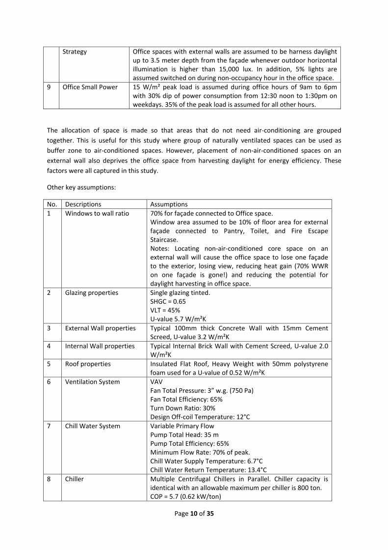
Strategy Office spaces with external walls are assumed to be harness daylight up to 3.5 meter depth from the façade whenever outdoor horizontal illumination is higher than 15,000 lux. In addition, 5% lights are assumed switched on during non‐occupancy hour in the office space.
9 Office Small Power 15 W/m² peak load is assumed during office hours of 9am to 6pm with 30% dip of power consumption from 12:30 noon to 1:30pm on weekdays. 35% of the peak load is assumed for all other hours.
The allocation of space is made so that areas that do not need air‐conditioning are grouped
together. This is useful for this study where group of naturally ventilated spaces can be used as
buffer zone to air‐conditioned spaces. However, placement of non‐air‐conditioned spaces on an
external wall also deprives the office space from harvesting daylight for energy efficiency. These
factors were all captured in this study.
Other key assumptions:
No. Descriptions Assumptions
1 Windows to wall ratio 70% for façade connected to Office space. Window area assumed to be 10% of floor area for external façade connected to Pantry, Toilet, and Fire Escape Staircase. Notes: Locating non‐air‐conditioned core space on an external wall will cause the office space to lose one façade to the exterior, losing view, reducing heat gain (70% WWR on one façade is gone!) and reducing the potential for daylight harvesting in office space.
2 Glazing properties Single glazing tinted. SHGC = 0.65 VLT = 45% U‐value 5.7 W/m²K
3 External Wall properties Typical 100mm thick Concrete Wall with 15mm Cement Screed, U‐value 3.2 W/m²K
4 Internal Wall properties Typical Internal Brick Wall with Cement Screed, U‐value 2.0 W/m²K
5 Roof properties Insulated Flat Roof, Heavy Weight with 50mm polystyrene foam used for a U‐value of 0.52 W/m²K
6 Ventilation System VAV Fan Total Pressure: 3” w.g. (750 Pa) Fan Total Efficiency: 65% Turn Down Ratio: 30% Design Off‐coil Temperature: 12°C
7 Chill Water System Variable Primary Flow Pump Total Head: 35 m Pump Total Efficiency: 65% Minimum Flow Rate: 70% of peak. Chill Water Supply Temperature: 6.7°C Chill Water Return Temperature: 13.4°C
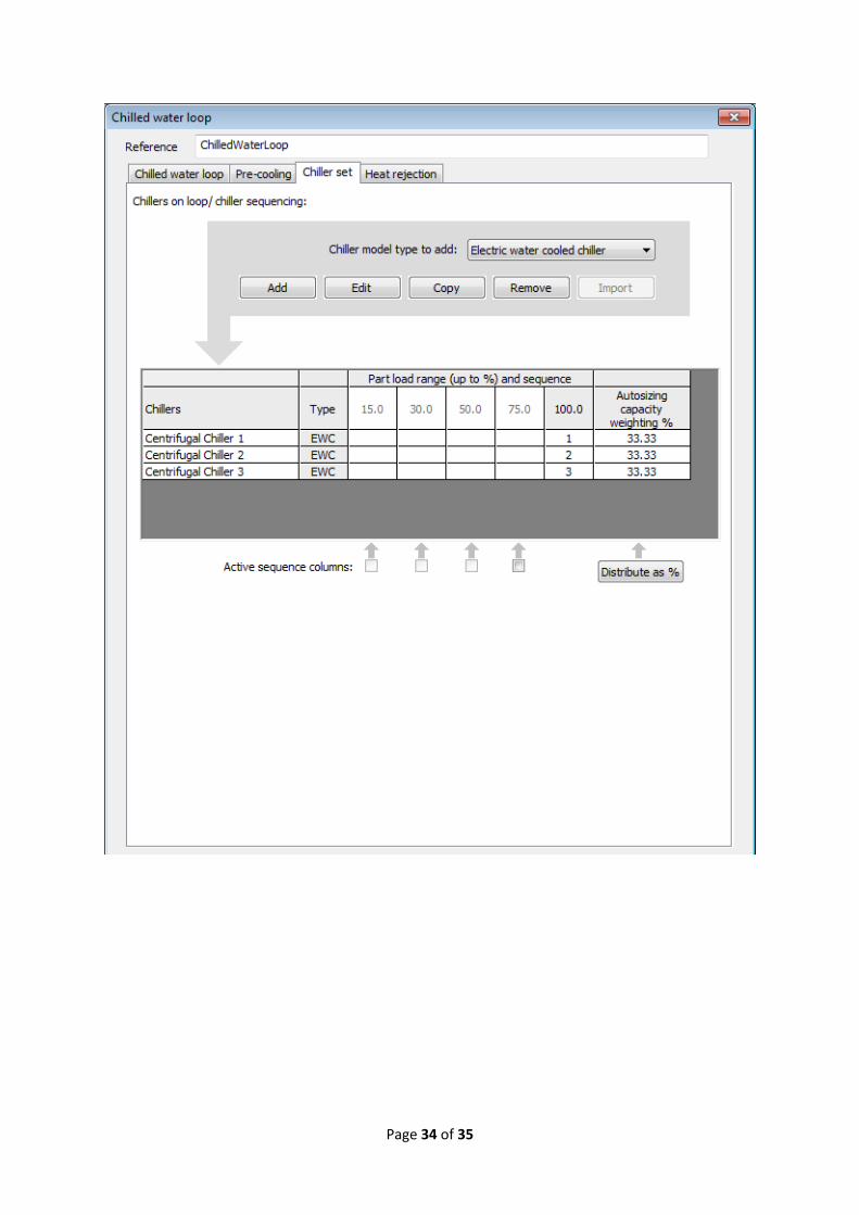
8 Chiller Multiple Centrifugal Chillers in Parallel. Chiller capacity is identical with an allowable maximum per chiller is 800 ton. COP = 5.7 (0.62 kW/ton)

Page 11 of 35
9 Condenser System Constant flow at rated condition (3 gpm/ton) Pump Total Head: 30 m Pump Total Efficiency: 65% Design Condenser Water Supply Temperature: 29.4°C Design Condenser Delta Temperature: 5.6°K
10 Cooling Tower Fan power at 0.025 kW/HRT
11 Fresh Air Supply Ashrae 62.1 (2007)
11 Infiltration The infiltration rate of the building will be based on assumption of a crack along the window perimeter. Windows are assumed to be 2.8m height (for 70% WWR with ribbon window layout) and each piece of window is 1.2 meter width. It is also assumed that 2 pieces of windows is required to make the total height of 2.8 meter. The assumption of crack coefficient is based on 0.13 (l s‐1 m‐1 Pa‐0.6) for weather‐stripped hinged window.1 The simulation study will use wind pressure coefficients taken from the Air Infiltration and Ventilation Centre’s publication Air Infiltration Calculation Techniques – An Applications Guide2. These coefficients are derived from wind tunnel experiments.
12 Office Occupancy Weekdays: 10 m²/person, 9am to 6pm, with 50% reduction at lunch time of 12:30 noon to 1:30pm. Weekends: Empty
13 Lift Core Lift Core is assumed to have an infiltration rate of 1 ach during occupancy hours and 0.5 during non‐occupancy hours. Lift power is ignored in this study because it will be the same for all the buildings and have a small influence on the total energy consumption of the building.
14 Façade and External Lights Façade and external lights are ignored in this study because it will be the same for all the buildings and have a small influence on the total energy consumption of the building.
15 Other Misc Power All other miscellaneous power use is ignored. These items includes potable water pumps, escalators, security access system, etc. because it will be the same for all the buildings and have a small influence on the total energy consumption of the building.
1 An Analysis and Data Summary of the AIVC’s Numerical Database. Technical Note AIVC 44, March 1994. Air Infiltration and Ventilation Centre. 2 Air Infiltration Calculation Techniques – An Applications Guide, Air Infiltration and Ventilation Centre. University of Warwick Science Park. Sovereign Court, Sir William Lyons Road, Coventry CV4 7EZ.

Page 12 of 35
3.6 TestCases19 building form, core location and orientations were created for this study. These test cases are as
presented below:
C0 C1 C2 C3 C4
C5 C6 C7 C8 C9
C10 C11 C12 C13 C14
C15 C16 C17 C18
Page 13 of 35
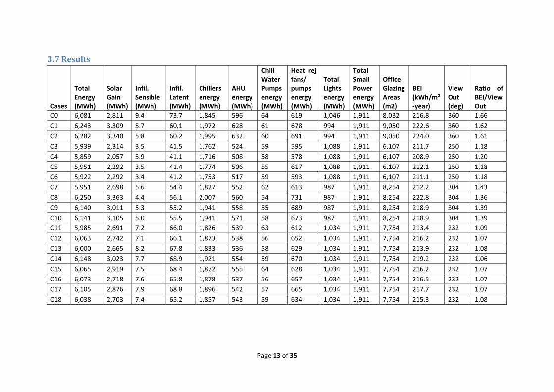
3.7 Results
Cases
Total Energy (MWh)
Solar Gain (MWh)
Infil. Sensible (MWh)
Infil. Latent (MWh)
Chillers energy (MWh)
AHU energy (MWh)
Chill Water Pumps energy (MWh)
Heat rej fans/ pumps energy (MWh)
Total Lights energy (MWh)
Total Small Power energy (MWh)
Office Glazing Areas (m2)
BEI (kWh/m²‐year)
View Out (deg)
Ratio of BEI/View Out
C0 6,081 2,811 9.4 73.7 1,845 596 64 619 1,046 1,911 8,032 216.8 360 1.66
C1 6,243 3,309 5.7 60.1 1,972 628 61 678 994 1,911 9,050 222.6 360 1.62
C2 6,282 3,340 5.8 60.2 1,995 632 60 691 994 1,911 9,050 224.0 360 1.61
C3 5,939 2,314 3.5 41.5 1,762 524 59 595 1,088 1,911 6,107 211.7 250 1.18
C4 5,859 2,057 3.9 41.1 1,716 508 58 578 1,088 1,911 6,107 208.9 250 1.20
C5 5,951 2,292 3.5 41.4 1,774 506 55 617 1,088 1,911 6,107 212.1 250 1.18
C6 5,922 2,292 3.4 41.2 1,753 517 59 593 1,088 1,911 6,107 211.1 250 1.18
C7 5,951 2,698 5.6 54.4 1,827 552 62 613 987 1,911 8,254 212.2 304 1.43
C8 6,250 3,363 4.4 56.1 2,007 560 54 731 987 1,911 8,254 222.8 304 1.36
C9 6,140 3,011 5.3 55.2 1,941 558 55 689 987 1,911 8,254 218.9 304 1.39
C10 6,141 3,105 5.0 55.5 1,941 571 58 673 987 1,911 8,254 218.9 304 1.39
C11 5,985 2,691 7.2 66.0 1,826 539 63 612 1,034 1,911 7,754 213.4 232 1.09
C12 6,063 2,742 7.1 66.1 1,873 538 56 652 1,034 1,911 7,754 216.2 232 1.07
C13 6,000 2,665 8.2 67.8 1,833 536 58 629 1,034 1,911 7,754 213.9 232 1.08
C14 6,148 3,023 7.7 68.9 1,921 554 59 670 1,034 1,911 7,754 219.2 232 1.06
C15 6,065 2,919 7.5 68.4 1,872 555 64 628 1,034 1,911 7,754 216.2 232 1.07
C16 6,073 2,718 7.6 65.8 1,878 537 56 657 1,034 1,911 7,754 216.5 232 1.07
C17 6,105 2,876 7.9 68.8 1,896 542 57 665 1,034 1,911 7,754 217.7 232 1.07
C18 6,038 2,703 7.4 65.2 1,857 543 59 634 1,034 1,911 7,754 215.3 232 1.08
Page 14 of 35
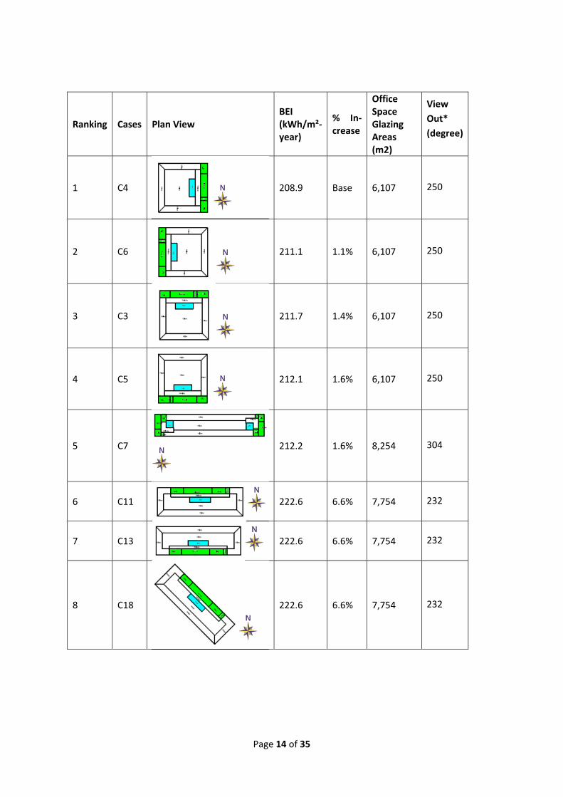
Ranking Cases Plan View BEI (kWh/m²‐year)
% In‐crease
Office Space Glazing Areas (m2)
View
Out*
(degree)
1 C4
208.9 Base 6,107 250
2 C6 211.1 1.1% 6,107 250
3 C3 211.7 1.4% 6,107 250
4 C5
212.1 1.6% 6,107 250
5 C7 212.2 1.6% 8,254 304
6 C11 222.6 6.6% 7,754 232
7 C13 222.6 6.6% 7,754 232
8 C18 222.6 6.6% 7,754 232

Page 15 of 35
9 C12
222.6 6.6% 7,754 232
10 C15 222.6 6.6% 7,754 232
11 C16 222.6 6.6% 7,754 232
12 C0 216.8 3.8% 8,032 360
13 C17 222.6 6.6% 7,754 232
14 C9 218.9 4.8% 8,254 304
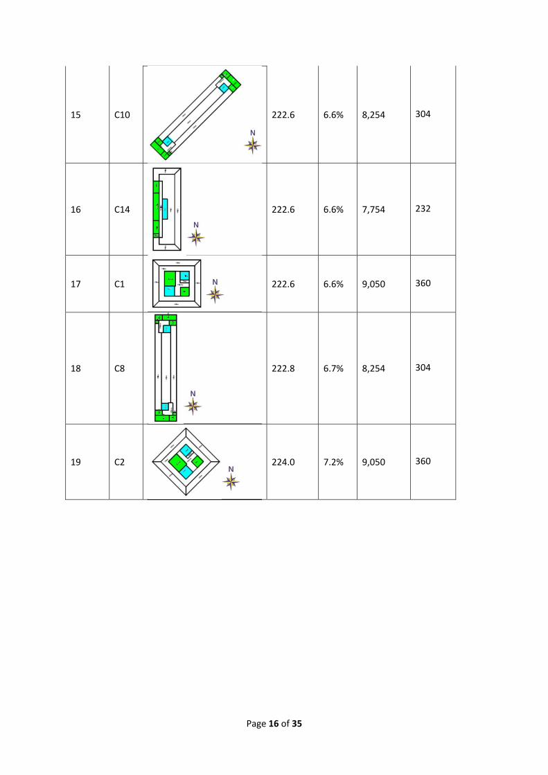
Page 16 of 35
15 C10 222.6 6.6% 8,254 304
16 C14
222.6 6.6% 7,754 232
17 C1
222.6 6.6% 9,050 360
18 C8
222.8 6.7% 8,254 304
19 C2 224.0 7.2% 9,050 360

Page 17 of 35
Cases Plan View
Ratio BEI/ View Out
% Decrease
View Out (degree)
BEI (kWh/m²‐year)
Office Glazing Areas (m2)
C0
0.60 0.0% 360 216.8 8,032
C1
0.62 ‐2.6% 360 222.6 9,050
C2
0.62 ‐3.2% 360 224.0 9,050
C7
0.70 ‐13.7% 304 212.2 8,254
C9 0.72 ‐16.4% 304 218.9 8,254
C10 0.72 ‐16.4% 304 218.9 8,254
C8 0.73 ‐17.8% 304 222.8 8,254

Page 18 of 35
C4
0.84 ‐27.9% 250 208.9 6,107
C6
0.84 ‐28.7% 250 211.1 6,107
C3
0.85 ‐28.9% 250 211.7 6,107
C5
0.85 ‐29.0% 250 212.1 6,107
C11
0.92 ‐34.5% 232 213.4 7,754
C13
0.92 ‐34.7% 232 213.9 7,754
C18
0.93 ‐35.1% 232 215.3 7,754
C12
0.93 ‐35.4% 232 216.2 7,754
C15
0.93 ‐35.4% 232 216.2 7,754
Page 19 of 35
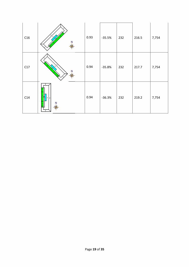
C16
0.93 ‐35.5% 232 216.5 7,754
C17
0.94 ‐35.8% 232 217.7 7,754
C14
0.94 ‐36.3% 232 219.2 7,754

Page 20 of 35
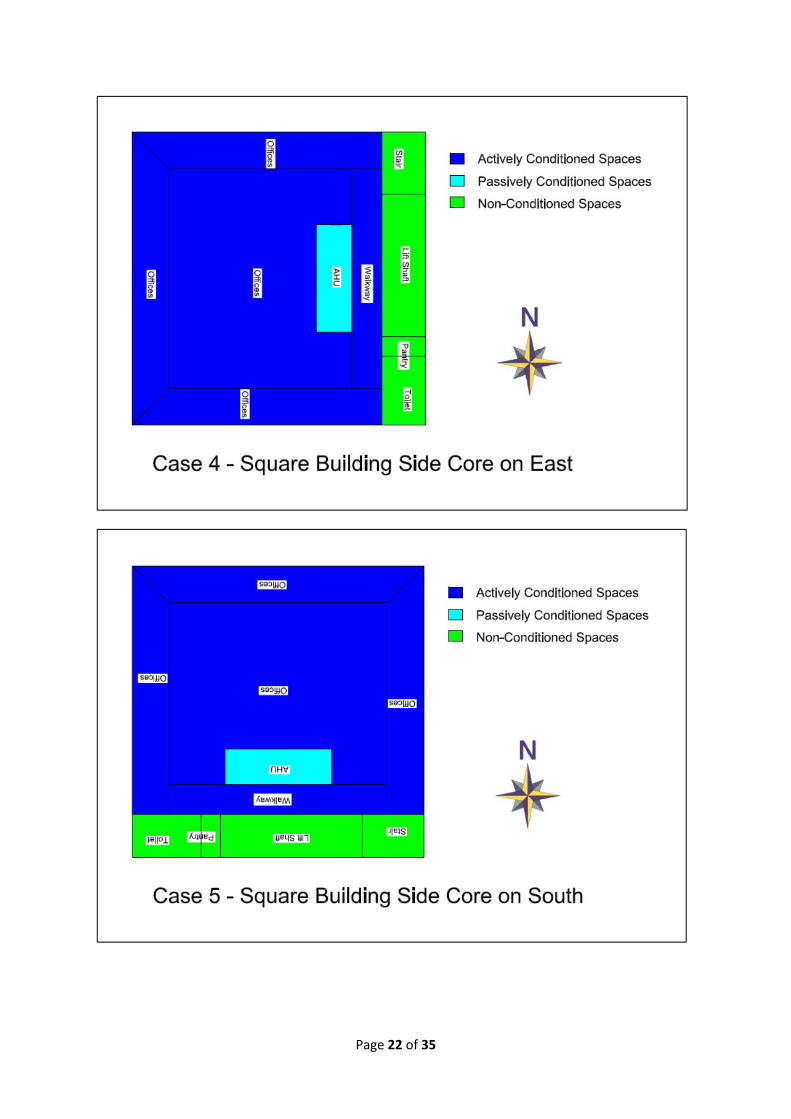
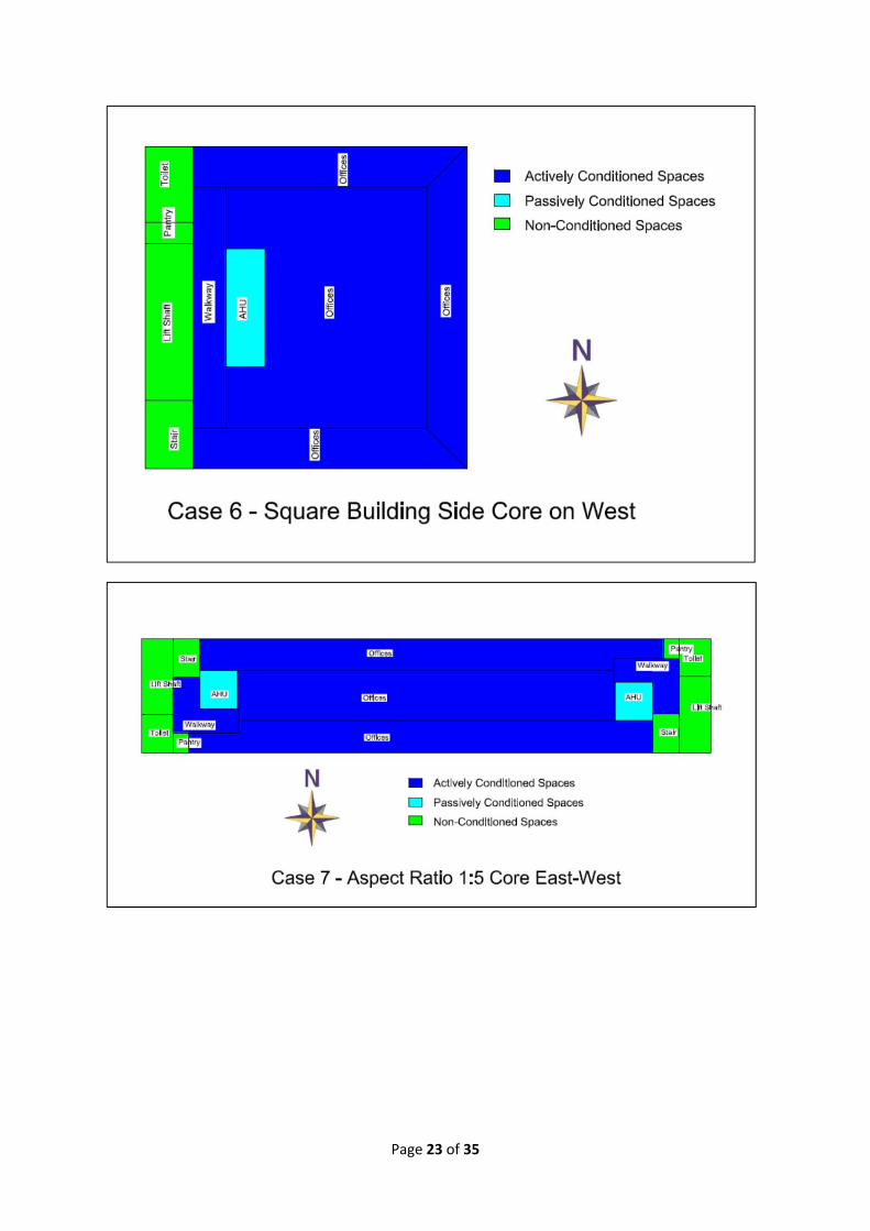
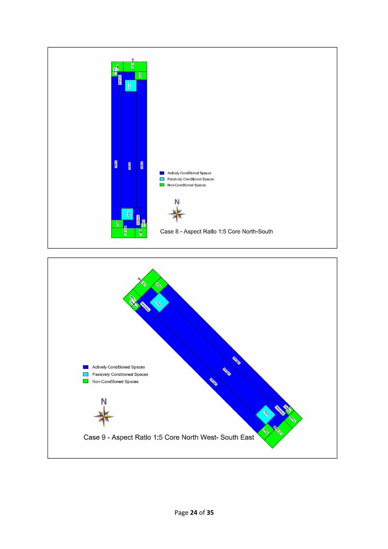
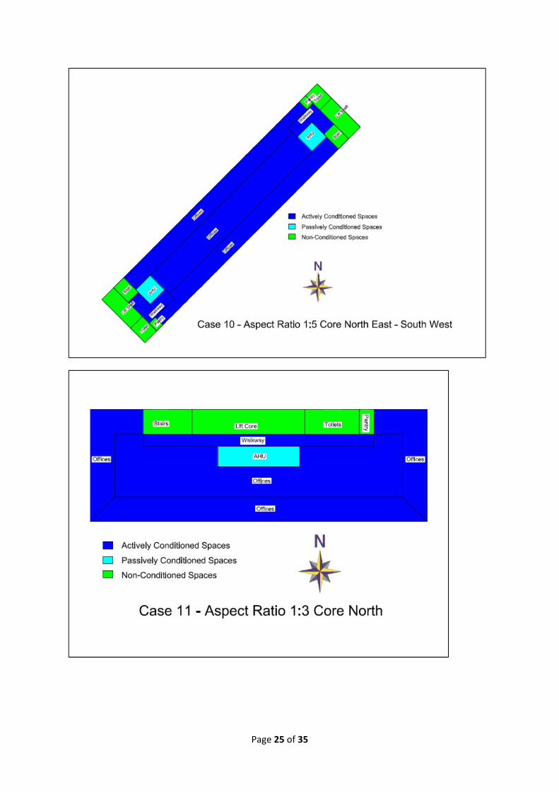
3.8 AppendixThe appendix provides further information adequate for this study to be repeated.
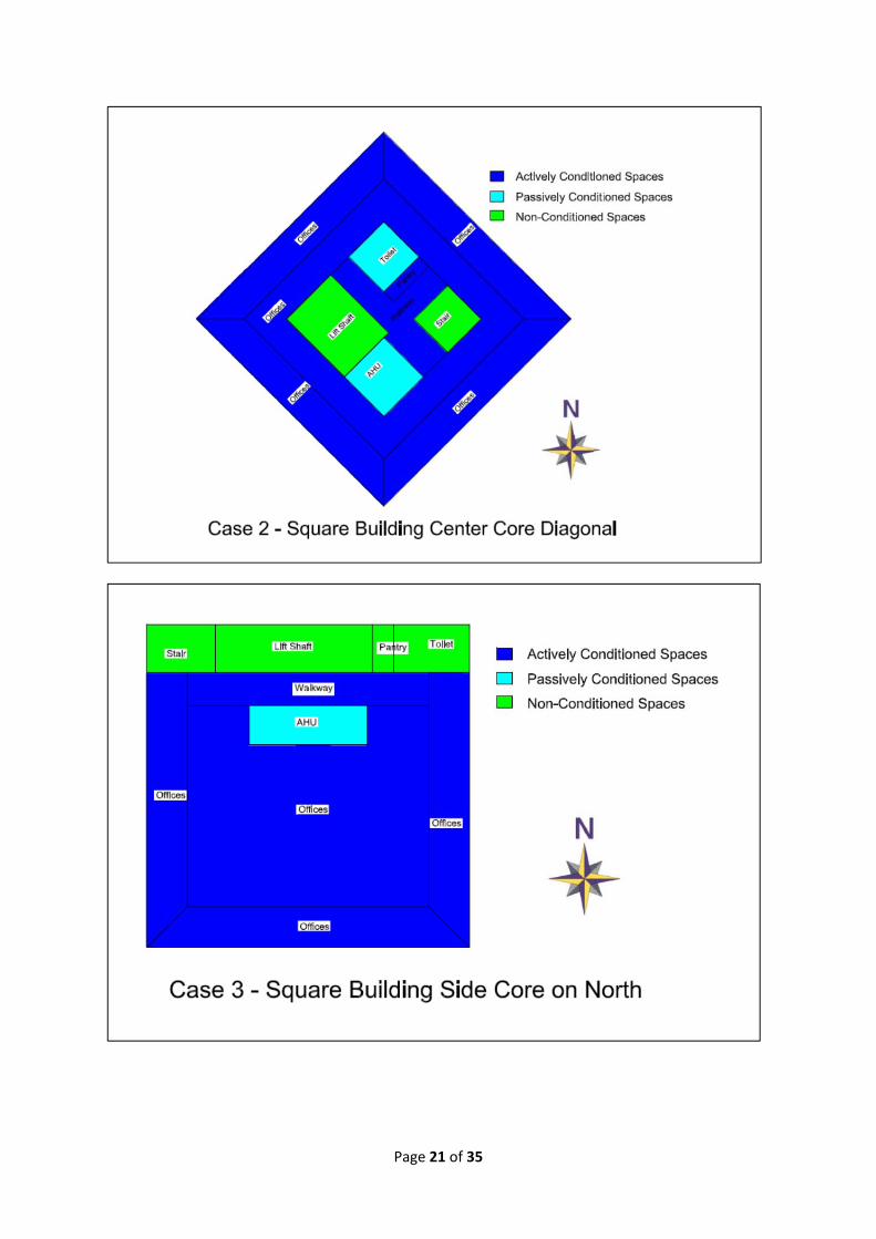
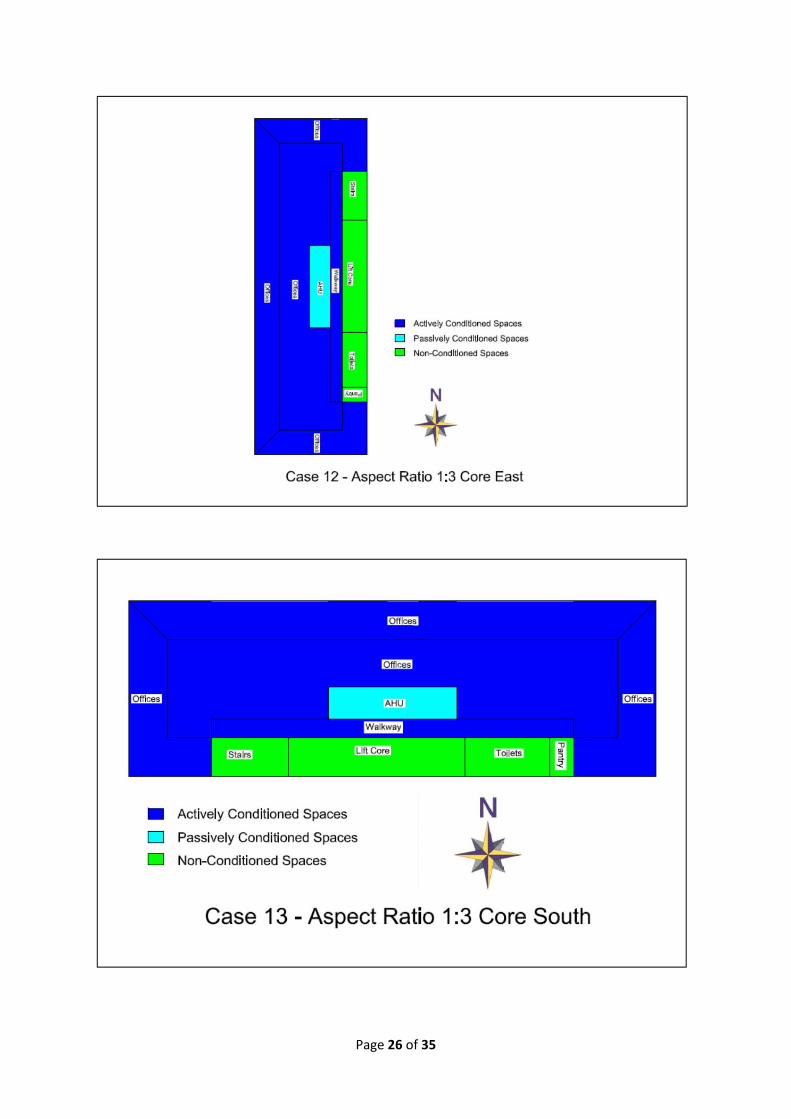
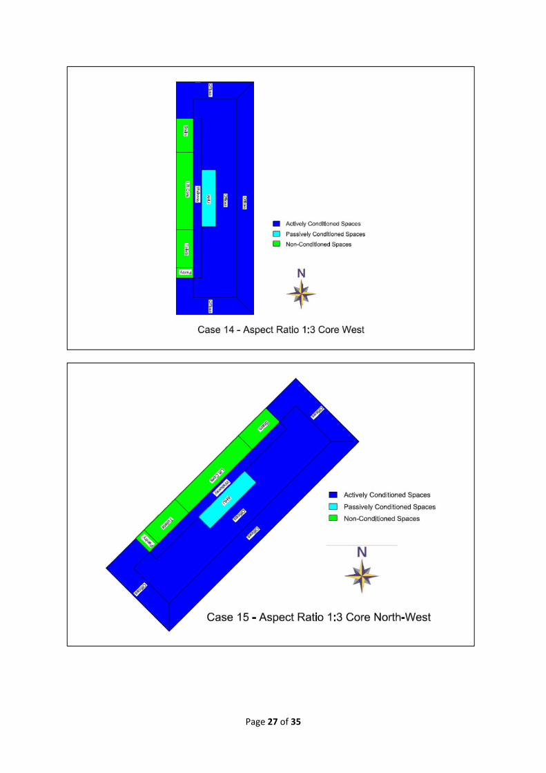
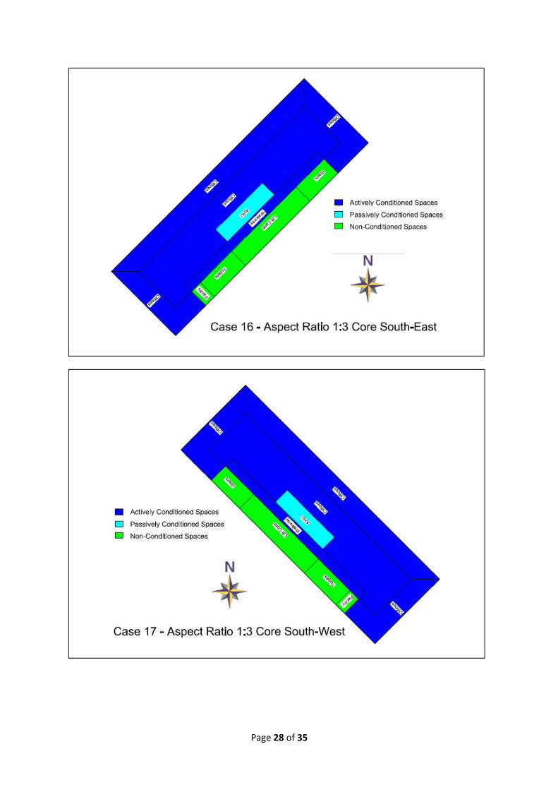
1. DetailedLayoutofEachCaseScenario
Page 21 of 35
Page 22 of 35
Page 23 of 35
Page 24 of 35
Page 25 of 35
Page 26 of 35
Page 27 of 35
Page 28 of 35

Page 29 of 35

Page 30 of 35
2. WeatherDataThe hourly weather data of Kuala Lumpur used in this chapter was based on a Test Reference
Year (TRY)3 weather data developed in University Teknologi Malaysia (UiTM) under DANCED
(Danish International Assistant) project for Energy Simulations for Buildings in Malaysia. The TRY
is based on 21 years (1975 to 1995) of weather data from the Malaysian Meteorological Station
in Subang, Klang Valley, Selangor. The hourly weather data that were obtained from this station
is as shown in Table A1 below.
Table A1: Weather data collected in Subang
Subang Meteorological Station
(Klang Valley, Selangor, Malaysia)
Longitude: 101deg 33'
Latitude: 3deg 7'
Parameters (hourly4) Units
Cloud cover [oktas]
Dry bulb temperature [°C]
Wet bulb temperature [°C]
Relative humidity [%]
Global solar radiation [100*MJ/m²]
Sunshine hours [hours]
Wind direction [deg.]
Wind speed [m/s]
A Test Reference year (TRY) consists of weather data for a given location. In order for the TRY to
be representative of the climate it was constructed on the basis of at least 10 years weather
data. The TRY is made up from actual monthly data (not average values) that are picked after
having been subjected to different types of analysis.
It should be noted that typical energy simulation program require 2 extra data that were not
collected by the Malaysian Meteorological Service, namely the direct and diffuse radiation. The
missing radiation data was calculated for the TRY via Erbs’ Estimation Model from the horizontal
global solar radiation.
Although not perfect, the TRY is currently the only known set of weather data for energy
simulation that was compiled based on statistical analysis and it has been used in many energy
simulations of various buildings in Malaysia with satisfactory results. This weather data was also
used for the development of the constants in the Overall Thermal Transmission Value (OTTV)
equation found in the Malaysia Standard (MS) 1525 (2007), Energy Efficiency in Non‐Residential
Building.
3 Reimann, G. (2000) Energy Simulations for Buildings in Malaysia, Test Reference Year, 18‐25.
4 The values are integrated over a period of one hour, but the exact time interval has not been specified.

Page 31 of 35
3. BuildingModel
Total 186 zones created for Case 0.
4. HVACDetailsofCase0Air Side Details per Floor
Water Side – 3 Chillers
Toilets AHUs
Lift Lobby Office N
Pantry Office E
Office W
Office S
Office C
VAV Controller

Page 32 of 35

Page 33 of 35
Page 34 of 35

Page 35 of 35