chapter 21 biochemical fuel cells - wiley · chapter 21 biochemical fuel cells eugenii katz, andrew...
TRANSCRIPT
Chapter 21Biochemical fuel cells
Eugenii Katz, Andrew N. Shipway and Itamar WillnerInstitute of Chemistry and The Farkas Center for Light-Induced Processes, The Hebrew University of Jerusalem,Jerusalem, 91904 Israel
1 INTRODUCTION
During the 20th century, energy consumption increased dra-matically and an unbalanced energy management exists.While there is no sign that this growth in demand will abate(particularly amongst the developing nations), there is nowan awareness of the transience of nonrenewable resourcesand the irreversible damage caused to the environment.In addition, there is a trend towards the miniaturizationand portability of computing and communications devices.These energy-demanding applications require small, lightpower sources that are able to sustain operation overlong periods of time, particularly in remote locations suchas space and exploration. Furthermore, advances in themedical sciences are leading to an increasing number ofimplantable electrically operated devices (e.g., pacemak-ers). These items need power supplies that will operate forextremely long durations as maintenance would necessitatesurgery. Ideally, implanted devices would take advantageof the natural fuel substances found in the body, and thuswould continue to draw power for as long as the subjectlives. Biofuel cells potentially offer solutions to all theseproblems, by taking nature’s solutions to energy generationand tailoring them to our own needs. They take readilyavailable substrates from renewable sources and convertthem into benign by-products with the generation of elec-tricity. Since they use concentrated sources of chemicalenergy, they can be small and light, and the fuel can evenbe taken from a living organism (e.g., glucose from theblood stream).
Biofuel cells use biocatalysts for the conversion of chem-ical energy to electrical energy.[1–8] As most organic sub-strates undergo combustion with the evolution of energy,the biocatalyzed oxidation of organic substances by oxy-gen or other oxidizers at two-electrode interfaces pro-vides a means for the conversion of chemical to electricalenergy. Abundant organic raw materials such as methanol,organic acids, or glucose can be used as substrates forthe oxidation process, and molecular oxygen or H2O2can act as the substrate being reduced. The extractablepower of a fuel cell (Pcell) is the product of the cellvoltage (Vcell) and the cell current (Icell) (equation (1)).Although the ideal cell voltage is affected by the dif-ference in the formal potentials of the oxidizer and fuelcompounds (E′
ox − E′fuel), irreversible losses in the volt-
age (η) as a result of kinetic limitations of the electrontransfer processes at the electrode interfaces, ohmic resis-tances and concentration gradients, lead to decreased values(equation (2)).
Pcell = Vcell × Icell (1)
Vcell = E′ox − E
′fuel − η (2)
Similarly, the cell current is controlled by the electrodesizes, the ion permeability and transport rates across themembrane separating the catholyte and anolyte compart-ments of the biofuel cell (specifically, the rate of electrontransfer at the respective electrode surfaces). These differentparameters collectively influence the biofuel cell power, and
Handbook of Fuel Cells – Fundamentals, Technology and Applications, Edited by Wolf Vielstich, Hubert A. Gasteiger, Arnold Lamm.Volume 1: Fundamentals and Survey of Systems. 2003 John Wiley & Sons, Ltd
2 Fuel cell principles, systems and applications
for improved efficiencies, the Vcell and Icell values shouldbe optimized.
Biofuel cells can use biocatalysts, enzymes or even wholecell organisms in one of two ways.[1–8] Either (i) the bio-catalysts can generate the fuel substrates for the cell bybiocatalytic transformations or metabolic processes, or (ii)the biocatalysts may participate in the electron transferchain between the fuel substrates and the electrode surfaces.Unfortunately, most redox enzymes do not take part indirect electron transfer with conductive supports, and there-fore a variety of electron mediators (electron relays) areused for the electrical contacting of the biocatalyst and theelectrode.[9] Recently, novel approaches have been devel-oped for the functionalization of electrode surfaces withmonolayers and multilayers consisting of redox enzymes,electrocatalysts and bioelectrocatalysts that stimulate elec-trochemical transformations at the electrode interfaces.[10]
The assembly of electrically contacted bioactive monolayerelectrodes could be advantageous for biofuel cell applica-tions as the biocatalyst and electrode support are integrated.This article summarizes recent advances in the tailoringof conventional microbial-based biofuel cells and describesnovel biofuel cell configurations based on biocatalytic inter-face structures integrated with the cathodes and anodes ofbiofuel cells.
2 MICROBIAL-BASED BIOFUEL CELLS
The use of entire microorganisms as microreactors infuel cells eliminates the need for the isolation of indi-vidual enzymes, and allows the active biomaterials towork under conditions close to their natural environ-ment, thus at a high efficiency. Whole microorganismscan be difficult to handle, however, requiring particu-lar conditions to remain alive, and their direct electro-chemical contact with an electrode support is virtuallyimpossible.
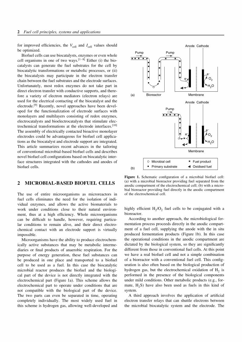
Microorganisms have the ability to produce electrochem-ically active substances that may be metabolic interme-diaries or final products of anaerobic respiration. For thepurpose of energy generation, these fuel substances canbe produced in one place and transported to a biofuelcell to be used as a fuel. In this case the biocatalyticmicrobial reactor produces the biofuel and the biologi-cal part of the device is not directly integrated with theelectrochemical part (Figure 1a). This scheme allows theelectrochemical part to operate under conditions that arenot compatible with the biological part of the device.The two parts can even be separated in time, operatingcompletely individually. The most widely used fuel inthis scheme is hydrogen gas, allowing well-developed and
O2
H2O
Pump
Anode Cathode
Pump
Membrane
Primary substrate
Fuel product
Oxidised fuel
Bioreactor
Microbial cell
Anode Cathode
Membrane
Pump
e−e−
O2
H2O
e−e−
(a)
(b)
Figure 1. Schematic configuration of a microbial biofuel cell:(a) with a microbial bioreactor providing fuel separated from theanodic compartment of the electrochemical cell; (b) with a micro-bial bioreactor providing fuel directly in the anodic compartmentof the electrochemical cell.
highly efficient H2/O2 fuel cells to be conjugated with abioreactor.
According to another approach, the microbiological fer-mentation process proceeds directly in the anodic compart-ment of a fuel cell, supplying the anode with the in situproduced fermentation products (Figure 1b). In this casethe operational conditions in the anodic compartment aredictated by the biological system, so they are significantlydifferent from those in conventional fuel cells. At this pointwe have a real biofuel cell and not a simple combinationof a bioreactor with a conventional fuel cell. This config-uration is also often based on the biological production ofhydrogen gas, but the electrochemical oxidation of H2 isperformed in the presence of the biological componentsunder mild conditions. Other metabolic products (e.g., for-mate, H2S) have also been used as fuels in this kind ofsystem.
A third approach involves the application of artificialelectron transfer relays that can shuttle electrons betweenthe microbial biocatalytic system and the electrode. The
Biochemical fuel cells 3
mediator molecules take electrons from the biologicalelectron transport chain of the microorganisms and transportthem to the anode of the biofuel cell. In this case, the bio-catalytic process performed in the microorganisms becomesdifferent from the natural one since the electron flow goesto the anode instead of to a natural electron acceptor. Sincethe natural electron acceptor is usually more efficient, it cancompete with the desired scheme, so it is usually removedfrom the system. In most cases, the microbiological systemoperates under anaerobic conditions (when O2 is removedfrom the system), allowing electron transport to the artificialelectron relays and, finally, to the anode.
2.1 Microbial bioreactors producing H2 forconventional fuel cells
Various bacteria and algae, for example Escherichiacoli, Enterobacter aerogenes, Clostridium butyricum,Clostridium acetobutylicum, and Clostridium perfringenshave been found to be active in hydrogen productionunder anaerobic conditions.[11–16] The most effective H2production is observed upon fermentation of glucose inthe presence of Clostridium butyricum (strain IFO 3847,35 µmol h−1 H2 evolution by 1 g of the microorganism at37 C).[17] This conversion of carbohydrate to hydrogen isachieved by a multienzyme system. In bacteria the routeis believed to involve glucose conversion to 2 mol ofpyruvate and 2 mol of NADH by the Embden–Meyerhofpathway. The pyruvate is then oxidized through apyruvate–ferredoxin oxidoreductase producing acetyl-CoA, CO2, and reduced ferredoxin. NADH–ferredoxinoxidoreductase oxidizes NADH and reduces ferredoxin.The reduced ferredoxin is reoxidized by the hydrogenaseto form hydrogen. As a result, 4 mol of hydrogen areproduced from 1 mol of glucose under ideal conditions(equations (3)–(6)). However, only ca. 1 mol of H2 per1 mol of glucose was obtained under optimal conditionsin a real system. Since the H2 yield is only ca. 25%of the theoretical yield,[18] the improvement of hydrogenproduction by genetic engineering techniques and screeningof new hydrogen-producing bacteria is possible forenhanced energy conversion. Glucose is an expensivesubstrate, and industrial wastewater containing nutritionalsubstrates for H2-producing bacteria have been successfullyapplied to produce hydrogen later used in a fuel cell.[17]
Glucose + 2NAD+
Multienzyme Embden–Meyerhof pathway−−−−−−−−−−−−−−−−−−−−−→ 2Pyruvate + 2NADH
(3)
Pyruvate + Ferredoxinox
Pyruvate–ferredoxin oxidoreductase−−−−−−−−−−−−−−−−−−→Acetyl-CoA + CO2 + Ferredoxinred (4)
NADH + Ferredoxinox
NADH-ferredoxin oxidoreductase−−−−−−−−−−−−−−−−−→NAD+ + Ferredoxinred (5)
Ferredoxinred + 2H+ Hydrogenase−−−−−−→ Ferredoxinox + H2 (6)
The immobilization of hydrogen-producing bacteria,Clostridium butyricum, has great value because thisstabilizes the relatively unstable hydrogenase system.In order to stabilize the biocatalytic performance, thebacteria were introduced into polymeric matrices, e.g.,polyacrylamide,[17] agar gel,[19, 20] and filter paper.[18] Theimmobilized microbial cells continuously produced H2under anaerobic conditions for a period of weeks, whereasnonimmobilized bacteria cells were fully deactivated in lessthan 2 days.[19]
A H2/O2 fuel cell (Pt-black/nickel mesh anode andPd-black/nickel mesh cathode separated by a nylon filterand operated at room temperature) was connected to abioreactor (Jar-fermentor) producing H2.[19, 20] The H2 gasproduced was collected and transported to the anodiccompartment of the fuel cell, where the gas was usedas a fuel (equation (7)). The current and voltage outputwere dependent on the rate of hydrogen production in thefermentor. For example, an open-circuit voltage (Voc) of0.95 V and short-circuit current density (isc) of 40 mA cm−2
were obtained at the H2 flow of 40 ml min−1. The biofuelcell operating at steady-state conditions for 7 days reveleda continuous current of between 500 and 550 mA.[20]
H2 −−−→ 2H+ + 2e−(to anode) (7)
2.2 Integrated microbial-based biofuel cellsproducing electrochemically activemetabolites in the anodic compartmentof biofuel cells
Microbial cells producing H2 gas during fermentationhave been immobilized directly in the anodic compartmentof a H2/O2 fuel cell.[21, 22] A rolled Pt-electrode wasintroduced into a suspension of Clostridium butyricummicroorganisms, then the suspension was polymerizedwith acrylamide to form a gel.[21] The fermentation wasconducted directly at the electrode surface, supplying theanode with the H2 fuel. In this case some additional by-products of the fermentation process (hydrogen, 0.60 mol;formic acid, 0.20 mol; acetic acid, 0.60 mol; lactic acid,
4 Fuel cell principles, systems and applications
0.15 mol)[21] could also be utilized as additional fuelcomponents. For example, pyruvate produced accordingto equation (3) can be alternatively oxidized to formatethrough a pyruvate–formate lyase (equation (8)).[17, 21] Themetabolically produced formate is directly oxidized at theanode when the fermentation solution passes the anodecompartment (equation (9)). The biofuel cell that includedca. 0.4 g of wet microbial cells (ca. 0.1 g of dry material)yielded upon optimal operating conditions the outputsVcell = 0.4 V and Icell = 0.6 mA.[21]
PyruvatePyruvate–formate lyase−−−−−−−−−−−−→ Formate (8)
HCOO− −−−→ CO2 + H+ + 2e−(to anode) (9)
It should be noted that in the case that a Pt-blackelectrode is used as an anode, oxidation of the originalsubstrate utilized by the microorganisms in the fermentationprocess (e.g., glucose) can contribute to the anodic current.Thus, the H2 provided by the microorganisms is the main,but not the only source of the anodic current.[23]
Other fuels have also been produced by microorgan-isms in the anodic compartments of biofuel cells. Thereare many microorganisms producing metabolically reducedsulfur-containing compounds (e.g., sulfides, S2−, HS−, sul-fites, SO3
2−). Sulfate-reducing bacteria (e.g., Desulfovib-rio desulfuricans) form a specialized group of anaerobicmicrobes that use sulfate (SO4
2−) as a terminal electronacceptor for respiration. These microorganisms yield S2−while using a substrate (e.g., lactate) as a source of elec-trons (equation (10)). This microbiological oxidation oflactate with the formation of sulfide has been used to drivean anodic process in biofuel cells.[24, 25] The metabolicallyproduced sulfide was oxidized directly at an electrode, pro-viding an anodic reaction that produces sulfate or thiosulfate(equations (11) and (12)).
Lactate + SO42− + 8H+ Bacteria−−−−→ S2− + 4H2O
+ Pyruvate (10)
S2− + 4H2O −−−→ SO42− + 8H+
+ 8e−(to anode) (11)
2S2− + 3H2O −−−→ S2O32− + 6H+
+ 8e−(to anode) (12)
The fermentation solution was composed of a microbesuspension (ca. 108 nonimmobilized cells per mL), withthe nutritional substrates (mainly lactate) under anaero-bic conditions. Accumulation of sulfides in the mediumresults in the inhibition of the metabolic bacteria process
because of their interaction with iron containing proteins(e.g., cytochromes), causing the electron transport systemsto be blocked. To prevent the toxic effect of H2S, the anodeshould effectively oxidize it. However, many metallic elec-trodes are poisoned by sulfide because of its strong and irre-versible adsorption. Thus, porous graphite electrodes wereused (100 cm2, impregnated with 10% (w/w) cobalt hydrox-ide, which in the presence of S2− undergoes a transitioninto a catalytically highly active cobalt oxide/cobalt sul-fide mixture).[24, 25] The biocatalytic anode was combinedwith an oxygen cathode (porous graphite electrode, 100 cm2
geometrical area, activated with iron(II) phthalocyanine andvanadium(V) compounds) separated with a cation-exchangemembrane in order to maintain anaerobic conditions inthe anodic compartment. In a test study,[25] the electri-cal output of the biofuel element composed of three cellsconnected in series was Voc = 2.8 V and Isc = 2.5–4.0 A(isc = ca. 30 mA cm−2). The element was loaded discon-tinuously for a period of 18 months, about 6 A being drawnfrom the cell for 40–60 min daily.
Microbiological fermentation under aerobic conditionsutilizes O2 as a terminal electron acceptor. It has beenshown that aerobic fermentation of Saccharomyces cere-visiae or Micrococcus cerificans bacteria in the presence ofglucose as the nutritional substrate in an anodic compart-ment of a biofuel cell results in an anodic current.[26–29] Abiofuel cell in such a system works as an O2-concentrationcell utilizing the potential difference produced at the cath-ode and anode due to the oxygen consumption in the anodiccompartment.
Table 1 summarizes the electrical output obtained inbiofuel cells operating without electron transfer mediatorsand using the natural products of microbial fermentation(e.g., H2, H2S) as the current providing species.
2.3 Microbial-based biofuel cells operating in thepresence of artificial electron relays
Reductive species generated by metabolic processes insidemicrobial cells are isolated from the external world by amicrobial membrane. Thus, contact of the microbial cellswith an electrode usually results in a very minute elec-tron transfer across the membrane of the microbes.[30]
In some specific cases, however, direct electron transferfrom the microbial cells to an anode surface is still possi-ble. The metal-reducing bacterium Shewanella putrefaciensMR-1 has been reported to have cytochromes in its outermembrane.[31] These electron carriers (i.e., cytochromes)are able to generate anodic current in the absence of termi-nal electron acceptors (under anaerobic conditions).[32, 33]
However, this is a rather exceptional example.
Biochemical fuel cells 5
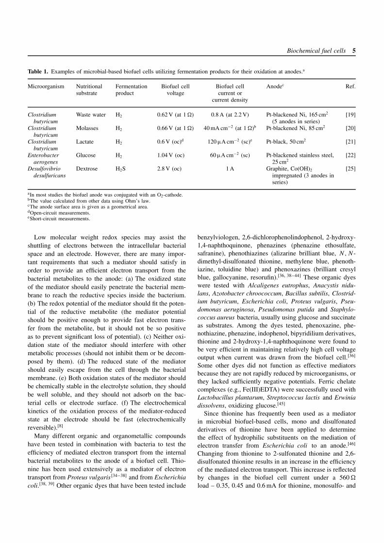
Table 1. Examples of microbial-based biofuel cells utilizing fermentation products for their oxidation at anodes.a
Microorganism Nutritional Fermentation Biofuel cell Biofuel cell Anodec Ref.substrate product voltage current or
current density
Clostridiumbutyricum
Waste water H2 0.62 V (at 1 ) 0.8 A (at 2.2 V) Pt-blackened Ni, 165 cm2
(5 anodes in series)[19]
Clostridiumbutyricum
Molasses H2 0.66 V (at 1 ) 40 mA cm−2 (at 1 )b Pt-blackened Ni, 85 cm2 [20]
Clostridiumbutyricum
Lactate H2 0.6 V (oc)d 120 µA cm−2 (sc)e Pt-black, 50 cm2 [21]
Enterobacteraerogenes
Glucose H2 1.04 V (oc) 60 µA cm−2 (sc) Pt-blackened stainless steel,25 cm2
[22]
Desulfovibriodesulfuricans
Dextrose H2S 2.8 V (oc) 1 A Graphite, Co(OH)2
impregnated (3 anodes inseries)
[25]
aIn most studies the biofuel anode was conjugated with an O2-cathode.bThe value calculated from other data using Ohm’s law.cThe anode surface area is given as a geometrical area.dOpen-circuit measurements.eShort-circuit measurements.
Low molecular weight redox species may assist theshuttling of electrons between the intracellular bacterialspace and an electrode. However, there are many impor-tant requirements that such a mediator should satisfy inorder to provide an efficient electron transport from thebacterial metabolites to the anode: (a) The oxidized stateof the mediator should easily penetrate the bacterial mem-brane to reach the reductive species inside the bacterium.(b) The redox potential of the mediator should fit the poten-tial of the reductive metabolite (the mediator potentialshould be positive enough to provide fast electron trans-fer from the metabolite, but it should not be so positiveas to prevent significant loss of potential). (c) Neither oxi-dation state of the mediator should interfere with othermetabolic processes (should not inhibit them or be decom-posed by them). (d) The reduced state of the mediatorshould easily escape from the cell through the bacterialmembrane. (e) Both oxidation states of the mediator shouldbe chemically stable in the electrolyte solution, they shouldbe well soluble, and they should not adsorb on the bac-terial cells or electrode surface. (f) The electrochemicalkinetics of the oxidation process of the mediator-reducedstate at the electrode should be fast (electrochemicallyreversible).[8]
Many different organic and organometallic compoundshave been tested in combination with bacteria to test theefficiency of mediated electron transport from the internalbacterial metabolites to the anode of a biofuel cell. Thio-nine has been used extensively as a mediator of electrontransport from Proteus vulgaris [34–38] and from Escherichiacoli.[38, 39] Other organic dyes that have been tested include
benzylviologen, 2,6-dichlorophenolindophenol, 2-hydroxy-1,4-naphthoquinone, phenazines (phenazine ethosulfate,safranine), phenothiazines (alizarine brilliant blue, N, N -dimethyl-disulfonated thionine, methylene blue, phenoth-iazine, toluidine blue) and phenoxazines (brilliant cresylblue, gallocyanine, resorufin).[36, 38–44] These organic dyeswere tested with Alcaligenes eutrophus, Anacystis nidu-lans, Azotobacter chroococcum, Bacillus subtilis, Clostrid-ium butyricum, Escherichia coli, Proteus vulgaris, Pseu-domonas aeruginosa, Pseudomonas putida and Staphylo-coccus aureus bacteria, usually using glucose and succinateas substrates. Among the dyes tested, phenoxazine, phe-nothiazine, phenazine, indophenol, bipyridilium derivatives,thionine and 2-hydroxy-1,4-naphthoquinone were found tobe very efficient in maintaining relatively high cell voltageoutput when current was drawn from the biofuel cell.[36]
Some other dyes did not function as effective mediatorsbecause they are not rapidly reduced by microorganisms, orthey lacked sufficiently negative potentials. Ferric chelatecomplexes (e.g., Fe(III)EDTA) were successfully used withLactobacillus plantarum, Streptococcus lactis and Erwiniadissolvens, oxidizing glucose.[45]
Since thionine has frequently been used as a mediatorin microbial biofuel-based cells, mono and disulfonatedderivatives of thionine have been applied to determinethe effect of hydrophilic substituents on the mediation ofelectron transfer from Escherichia coli to an anode.[46]
Changing from thionine to 2-sulfonated thionine and 2,6-disulfonated thionine results in an increase in the efficiencyof the mediated electron transport. This increase is reflectedby changes in the biofuel cell current under a 560
load – 0.35, 0.45 and 0.6 mA for thionine, monosulfo- and
6 Fuel cell principles, systems and applications
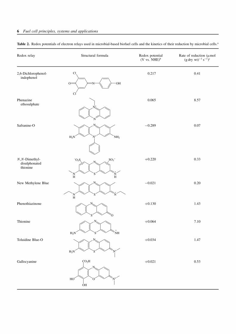
Table 2. Redox potentials of electron relays used in microbial-based biofuel cells and the kinetics of their reduction by microbial cells.a
Redox relay Structural formula Redox potential(V vs. NHE)b
Rate of reduction (µmol(g dry wt)−1 s−1)c
2,6-Dichlorophenol-indophenol
NO
Cl
Cl
OH
0.217 0.41
Phenazineethosulphate
N
N+
0.065 8.57
Safranine-O
N+
N
H2N NH2
−0.289 0.07
N ,N-Dimethyl-disulphonatedthionine
S
N
NN
−O3S SO3−
+
HH
+0.220 0.33
New Methylene Blue
N S
N
NH
+
−0.021 0.20
Phenothiazinone
S
N
O
+0.130 1.43
Thionine
S
N
H2N NH+
+0.064 7.10
Toluidine Blue-O
S
N
H2N N+
+0.034 1.47
Gallocyanine
O
N
HO N+
OH
CO2H +0.021 0.53
Biochemical fuel cells 7
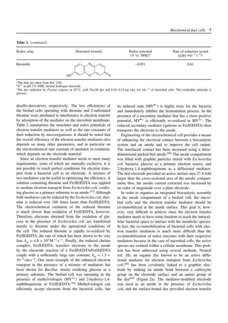
Table 2. (continued )
Redox relay Structural formula Redox potential(V vs. NHE)b
Rate of reduction (µmol(g dry wt)−1 s−1)c
Resorufin
O
N
HO O
−0.051 0.61
aThe data are taken from Ref. [38].bE
′ at pH 7.0. NHE, normal hydrogen electrode.cThe dye reduction by Proteus vulgaris at 30 C, with 50 µM dye and 0.10–0.15 mg (dry wt) mL−1 of microbial cells. The oxidizable substrate isglucose.
disulfo-derivatives, respectively. The low efficiencies ofthe biofuel cells operating with thionine and 2-sulfonatedthionine were attributed to interference to electron transferby adsorption of the mediator on the microbial membrane.Table 2 summarizes the structures and redox potentials ofelectron transfer mediators as well as the rate constants oftheir reduction by microorganisms. It should be noted thatthe overall efficiency of the electron transfer mediators alsodepends on many other parameters, and in particular onthe electrochemical rate constant of mediator re-oxidation,which depends on the electrode material.
Since an electron transfer mediator needs to meet manyrequirements, some of which are mutually exclusive, it isnot possible to reach perfect conditions for electron trans-port from a bacterial cell to an electrode. A mixture oftwo mediators can be useful in optimizing the efficiency. Asolution containing thionine and Fe(III)EDTA was appliedto mediate electron transport from Escherichia coli, oxidiz-ing glucose as a primary substrate to an anode.[47] Althoughboth mediators can be reduced by the Escherichia coli, thio-nine is reduced over 100 times faster than Fe(III)EDTA.The electrochemical oxidation of the reduced thionineis much slower than oxidation of Fe(II)EDTA, however.Therefore, electrons obtained from the oxidation of glu-cose in the presence of Escherichia coli are transferredmainly to thionine under the operational conditions ofthe cell. The reduced thionine is rapidly re-oxidized byFe(III)EDTA, the rate of which has been shown to be veryfast, ket = 4.8 × 10⁴ M−1 s−1. Finally, the reduced chelatecomplex, Fe(II)EDTA, transfers electrons to the anodeby the electrode reaction of a Fe(III)EDTA/Fe(II)EDTAcouple with a sufficiently large rate constant, kel = 1.5 ×10⁻² cm s−1. One more example of the enhanced electrontransport in the presence of a mixture of mediators hasbeen shown for Bacillus strains oxidizing glucose as aprimary substrate. The biofuel cell was operating in thepresence of methylviologen (MV2+) and 2-hydroxy-1,4-naphthoquinone or Fe(III)EDTA.[16] Methylviologen canefficiently accept electrons from the bacterial cells, but
its reduced state (MVž+) is highly toxic for the bacteriaand immediately inhibits the fermentation process. In thepresence of a secondary mediator that has a more positivepotential, MVž+ is efficiently re-oxidized to MV2+. Thereduced secondary mediator (quinone or Fe(II)EDTA) thentransports the electrons to the anode.
Engineering of the electrochemical cell provides a meansof enhancing the electrical contact between a biocatalyticsystem and an anode and to improve the cell output.The interfacial contact has been increased using a three-dimensional packed bed anode.[48] The anode compartmentwas filled with graphite particles mixed with Escherichiacoli bacteria, glucose as a primary electron source, and2-hydroxy-1,4-naphthoquinone as a diffusional mediator.The bed electrode provided an active surface area 27.4-foldlarger than the cross-sectional area of the anodic compart-ment, thus, the anodic current extracted was increased byan order of magnitude over a plate electrode.
In order to organize an integrated biocatalytic assemblyin the anode compartment of a biofuel cell, the micro-bial cells and the electron transfer mediator should beco-immobilized at the anode surface. This goal is, how-ever, very difficult to achieve since the electron transfermediator needs to have some freedom to reach the intracel-lular bacterial space to interact with the metabolic species.In fact, the co-immobilization of bacterial cells with elec-tron transfer mediators is much more difficult than theco-immobilization of redox enzymes with their respectivemediators because in the case of microbial cells, the activespecies are isolated within a cellular membrane. This prob-lem has been addressed using several methods. Neutralred (1), an organic dye known to be an active diffu-sional mediator for electron transport from Escherichiacoli,[40] has been covalently linked to a graphite elec-trode by making an amide bond between a carboxylicgroup on the electrode surface and an amino group ofthe dye[49] (Figure 2a). The mediator-modified electrodewas used as an anode in the presence of Escherichiacoli, and the surface-bound dye provided electron transfer
8 Fuel cell principles, systems and applications
Anode Microbial cell(E. coli )
Acetate
Metabolism
Reductants
Products
e−
e−
Mediator
N
N
H2N NH
+
(1)
(a)
Anode Microbial cell(Proteus vulgaris)
Glucose
Metabolism
Reductants
Products
e−
NH
O
Oxidized mediator
Reduced mediator
S
N
H2N NH2+
(2)
(b)
Anode Microbial cell(Desulfovibrio desulfuricans)
Glucose
Metabolism
Reductants
Products
e−
e−
Mediator
NC
NC CN
CN
(3)
(c)
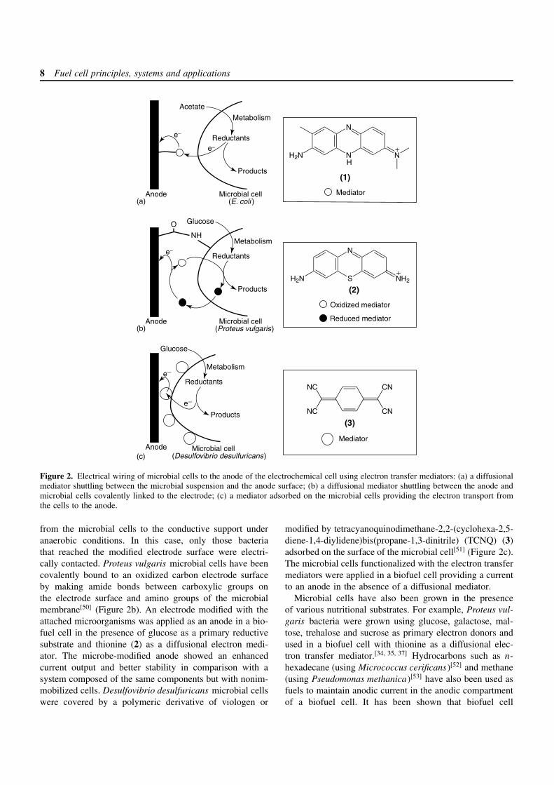
Figure 2. Electrical wiring of microbial cells to the anode of the electrochemical cell using electron transfer mediators: (a) a diffusionalmediator shuttling between the microbial suspension and the anode surface; (b) a diffusional mediator shuttling between the anode andmicrobial cells covalently linked to the electrode; (c) a mediator adsorbed on the microbial cells providing the electron transport fromthe cells to the anode.
from the microbial cells to the conductive support underanaerobic conditions. In this case, only those bacteriathat reached the modified electrode surface were electri-cally contacted. Proteus vulgaris microbial cells have beencovalently bound to an oxidized carbon electrode surfaceby making amide bonds between carboxylic groups onthe electrode surface and amino groups of the microbialmembrane[50] (Figure 2b). An electrode modified with theattached microorganisms was applied as an anode in a bio-fuel cell in the presence of glucose as a primary reductivesubstrate and thionine (2) as a diffusional electron medi-ator. The microbe-modified anode showed an enhancedcurrent output and better stability in comparison with asystem composed of the same components but with nonim-mobilized cells. Desulfovibrio desulfuricans microbial cellswere covered by a polymeric derivative of viologen or
modified by tetracyanoquinodimethane-2,2-(cyclohexa-2,5-diene-1,4-diylidene)bis(propane-1,3-dinitrile) (TCNQ) (3)adsorbed on the surface of the microbial cell[51] (Figure 2c).The microbial cells functionalized with the electron transfermediators were applied in a biofuel cell providing a currentto an anode in the absence of a diffusional mediator.
Microbial cells have also been grown in the presenceof various nutritional substrates. For example, Proteus vul-garis bacteria were grown using glucose, galactose, mal-tose, trehalose and sucrose as primary electron donors andused in a biofuel cell with thionine as a diffusional elec-tron transfer mediator.[34, 35, 37] Hydrocarbons such as n-hexadecane (using Micrococcus cerificans)[52] and methane(using Pseudomonas methanica)[53] have also been used asfuels to maintain anodic current in the anodic compartmentof a biofuel cell. It has been shown that biofuel cell
Biochemical fuel cells 9
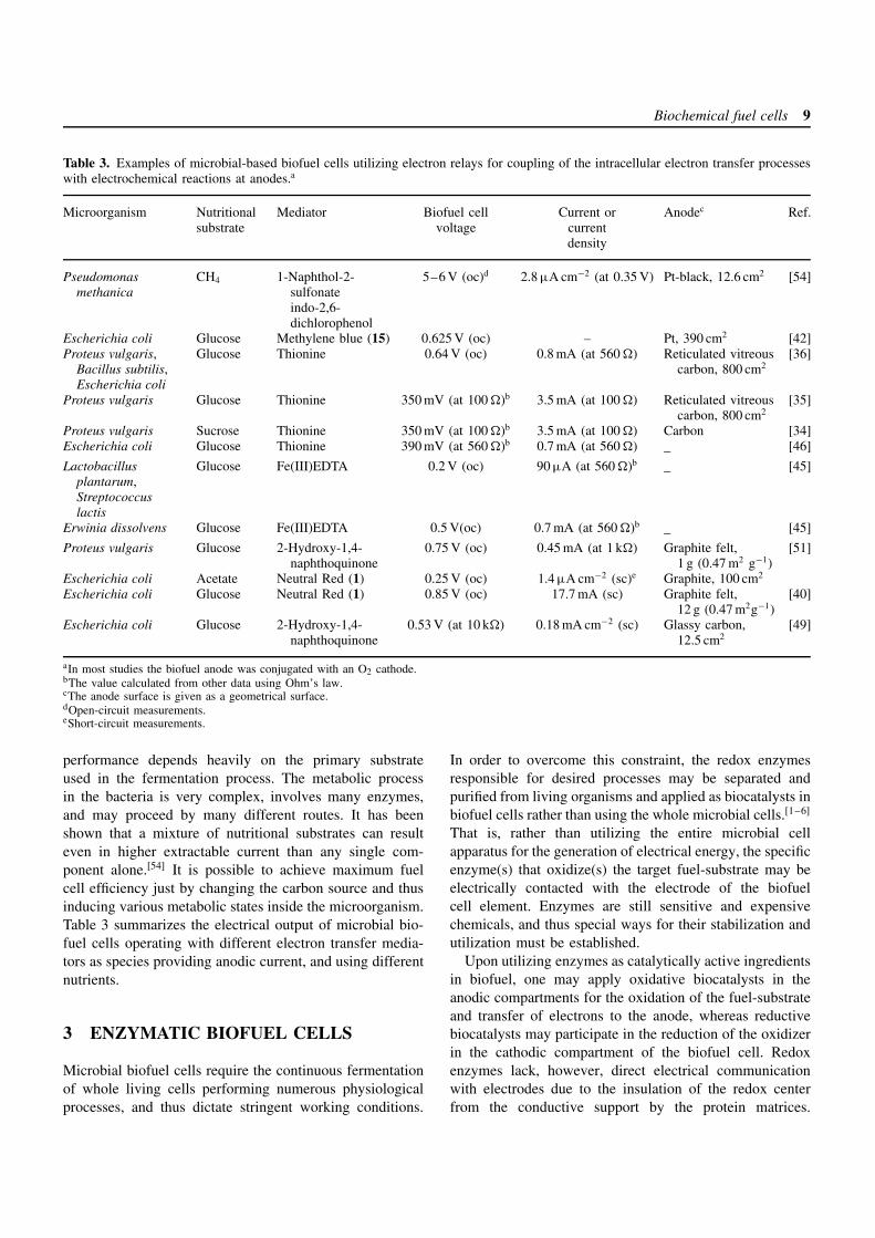
Table 3. Examples of microbial-based biofuel cells utilizing electron relays for coupling of the intracellular electron transfer processeswith electrochemical reactions at anodes.a
Microorganism Nutritionalsubstrate
Mediator Biofuel cellvoltage
Current orcurrentdensity
Anodec Ref.
Pseudomonasmethanica
CH4 1-Naphthol-2-sulfonateindo-2,6-dichlorophenol
5–6 V (oc)d 2.8 µA cm−2 (at 0.35 V) Pt-black, 12.6 cm2 [54]
Escherichia coli Glucose Methylene blue (15) 0.625 V (oc) – Pt, 390 cm2 [42]Proteus vulgaris,
Bacillus subtilis,Escherichia coli
Glucose Thionine 0.64 V (oc) 0.8 mA (at 560 ) Reticulated vitreouscarbon, 800 cm2
[36]
Proteus vulgaris Glucose Thionine 350 mV (at 100 )b 3.5 mA (at 100 ) Reticulated vitreouscarbon, 800 cm2
[35]
Proteus vulgaris Sucrose Thionine 350 mV (at 100 )b 3.5 mA (at 100 ) Carbon [34]Escherichia coli Glucose Thionine 390 mV (at 560 )b 0.7 mA (at 560 ) – [46]
Lactobacillusplantarum,Streptococcuslactis
Glucose Fe(III)EDTA 0.2 V (oc) 90 µA (at 560 )b– [45]
Erwinia dissolvens Glucose Fe(III)EDTA 0.5 V(oc) 0.7 mA (at 560 )b– [45]
Proteus vulgaris Glucose 2-Hydroxy-1,4-naphthoquinone
0.75 V (oc) 0.45 mA (at 1 k) Graphite felt,1 g (0.47 m2 g−1)
[51]
Escherichia coli Acetate Neutral Red (1) 0.25 V (oc) 1.4 µA cm−2 (sc)e Graphite, 100 cm2
Escherichia coli Glucose Neutral Red (1) 0.85 V (oc) 17.7 mA (sc) Graphite felt,12 g (0.47 m2g−1)
[40]
Escherichia coli Glucose 2-Hydroxy-1,4-naphthoquinone
0.53 V (at 10 k) 0.18 mA cm−2 (sc) Glassy carbon,12.5 cm2
[49]
aIn most studies the biofuel anode was conjugated with an O2 cathode.bThe value calculated from other data using Ohm’s law.cThe anode surface is given as a geometrical surface.dOpen-circuit measurements.eShort-circuit measurements.
performance depends heavily on the primary substrateused in the fermentation process. The metabolic processin the bacteria is very complex, involves many enzymes,and may proceed by many different routes. It has beenshown that a mixture of nutritional substrates can resulteven in higher extractable current than any single com-ponent alone.[54] It is possible to achieve maximum fuelcell efficiency just by changing the carbon source and thusinducing various metabolic states inside the microorganism.Table 3 summarizes the electrical output of microbial bio-fuel cells operating with different electron transfer media-tors as species providing anodic current, and using differentnutrients.
3 ENZYMATIC BIOFUEL CELLS
Microbial biofuel cells require the continuous fermentationof whole living cells performing numerous physiologicalprocesses, and thus dictate stringent working conditions.
In order to overcome this constraint, the redox enzymesresponsible for desired processes may be separated andpurified from living organisms and applied as biocatalysts inbiofuel cells rather than using the whole microbial cells.[1–6]
That is, rather than utilizing the entire microbial cellapparatus for the generation of electrical energy, the specificenzyme(s) that oxidize(s) the target fuel-substrate may beelectrically contacted with the electrode of the biofuelcell element. Enzymes are still sensitive and expensivechemicals, and thus special ways for their stabilization andutilization must be established.
Upon utilizing enzymes as catalytically active ingredientsin biofuel, one may apply oxidative biocatalysts in theanodic compartments for the oxidation of the fuel-substrateand transfer of electrons to the anode, whereas reductivebiocatalysts may participate in the reduction of the oxidizerin the cathodic compartment of the biofuel cell. Redoxenzymes lack, however, direct electrical communicationwith electrodes due to the insulation of the redox centerfrom the conductive support by the protein matrices.
10 Fuel cell principles, systems and applications
Several methods have been applied to electrically contactredox enzymes and electrode supports.[9, 10, 55]
In the following sections, the engineering of biocatalyticelectrodes for the oxidation of potential fuel substrates(biocatalytic anodes) and for the reduction of oxidizers(biocatalytic cathodes) is described. These electrodes arethen integrated into biofuel cell elements and the outputefficiencies of the bioelectronic devices are addressed.
3.1 Anodes for biofuel cells based onenzyme-catalyzed oxidative reactions
The electrochemical oxidation of fuels can be biocatalyzedby enzymes communicating electrically with electrodes.Different classes of oxidative enzymes (e.g., oxidases,dehydrogenases) require the application of different molec-ular tools to establish this electrical communication.[9, 10]
Electron transfer mediators shuttling electrons between theenzyme active centers and electrodes are usually needed forthe efficient electrical communication of flavin adenine din-ucleotide FAD-containing oxidases (e.g., glucose oxidase(GOx)). NAD(P)+-dependent dehydrogenases (e.g., lactatedehydrogenase) require NAD(P)+-co-factor and an elec-trode catalytically active for the oxidation of NAD(P)H andregeneration of NAD(P)+ to establish an electrical contactwith the electrode.
3.1.1 Anodes based on the bioelectrocatalyzedoxidation of NAD(P)H
The nicotinamide redox co-factors (NAD+ and NADP+)play important roles in biological electron transport, act-ing as carriers of electrons and activating the biocatalyticfunctions of dehydrogenases, the vast majority of redoxenzymes. The application of NAD(P)+-dependent enzymes(e.g., lactate dehydrogenase, EC 1.1.1.27; alcohol dehydro-genase, EC 1.1.1.71; glucose dehydrogenase, EC 1.1.1.118)in biofuel cells allows the use of many organic materi-als such as lactate, glucose and alcohols as fuels. Thebiocatalytic oxidation of these substrates requires the effi-cient electrochemical regeneration of NAD(P)+-co-factorsin the anodic compartment of the cells. The biocatalyt-ically produced NAD(P)H co-factors participating in theanodic process transports electrons from the enzymes tothe anode, and the subsequent electrochemical oxidation ofthe reduced co-factors regenerates the biocatalytic functionsof the system.
In aqueous solution at pH 7.0, the thermodynamic redoxpotential (E′) for NAD(P)+/NAD(P)H is ca. −0.56 V (vs.the saturated calomel electrode (SCE)) – sufficiently neg-ative for anode operation. Electrochemistry of NAD(P)Hhas been studied extensively, and it has been demonstrated
that the electrochemical oxidation process is highly irre-versible and proceeds with large overpotentials (η) (ca. 0.4,0.7 and 1 V vs. SCE at carbon, Pt and Au electrodes,respectively).[9, 56] Strong adsorption of NAD(P)H andNAD(P)+ (e.g., on Pt, Au, glassy carbon and pyrolyticgraphite) generally poisons the electrode surface and inhi-bits the oxidation process. Furthermore, NAD(P)+ acts asan inhibitor for the direct oxidation of NAD(P)H, andadsorbed NAD(P)H can be oxidized to undesired productsthat lead to the degradation of the co-factor (e.g., to NAD+-dimers). Thus, the noncatalyzed electrochemical oxidationof NAD(P)H is not appropriate for use in workable bio-fuel cells. For the efficient electrooxidation of NAD(P)H,mediated electrocatalysis is necessary.[9, 56] Several immo-bilization techniques have been applied for the preparationof mediator-modified electrodes: The mediator moleculescan be adsorbed directly onto electrodes, incorporated intopolymer layers, or covalently linked to functional groupson electrode surfaces.[56]
A biofuel cell based on the electrocatalytic regenera-tion of NAD+ at a modified anode has been developed.[57]
Glucose dehydrogenase (EC 1.1.1.47) was immobilized ina porous glass located in the anode compartment of thebiofuel cell. The enzyme oxidized the substrate (glucose)and produced the reduced state of the co-factor (NADH).The reduced co-factor reached the anode surface diffusion-ally (Meldola Blue was adsorbed at the graphite electrode,ca. 1 × 10⁻⁹ mol cm−2), where it was oxidized to NAD+.The biocatalytic anode was coupled to a Pt-cathode thatreduced water to hydrogen and the biofuel cell providedVoc = 300 mV and isc = 220 µA cm−2 over a period of sev-eral hours.
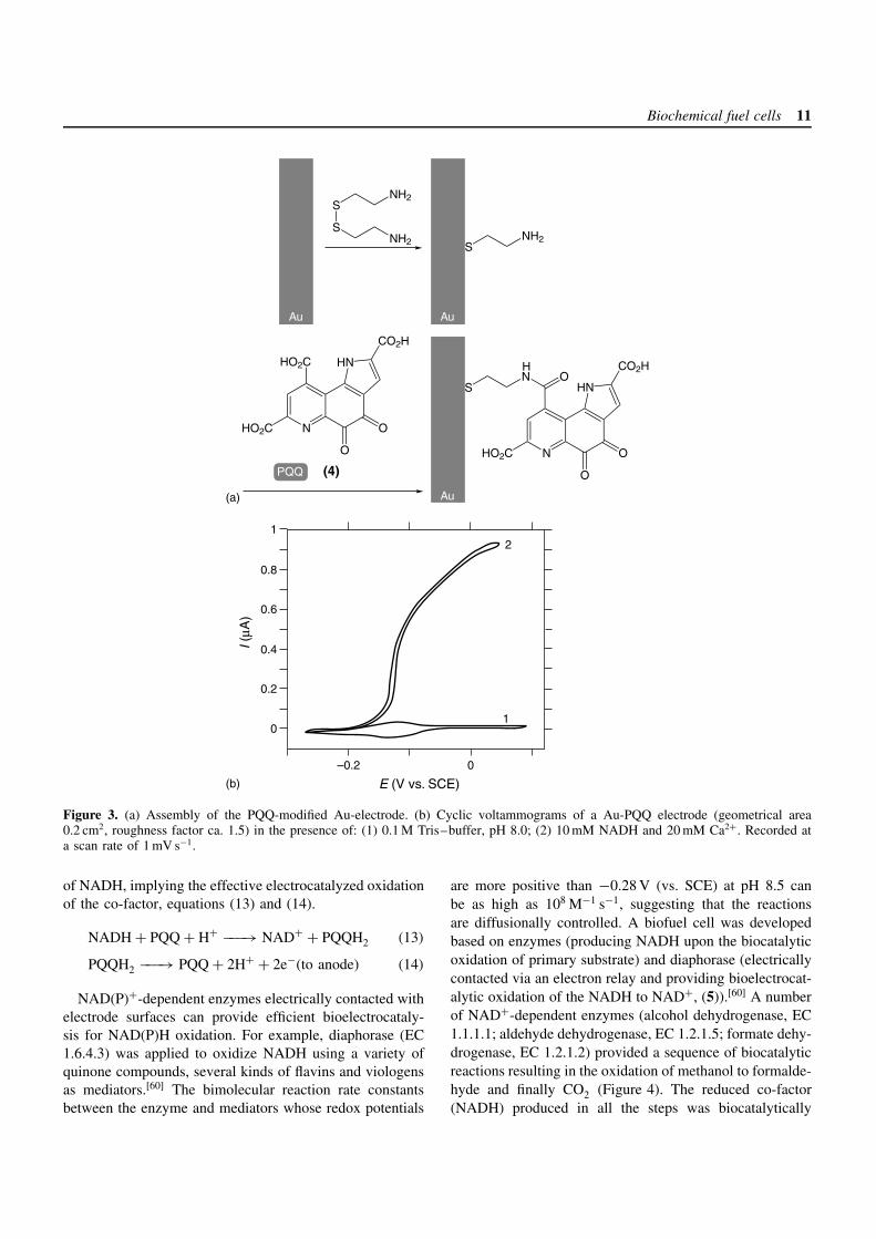
The covalent coupling of redox mediators to self-assem-bled monolayers on Au-electrode surfaces has an importantadvantage for the preparation of multi-component organizedsystems.[58] Pyrroloquinoline quinone (PQQ, (4)) can becovalently attached to amino groups of a cystamine mono-layer assembled on a Au surface (Figure 3a). The resultingelectrode demonstrates good electrocatalytic activity forNAD(P)H oxidation, particularly in the presence of Ca2+-cations as promoters (Figure 3b).[59] A quasi-reversibleredox wave at the formal potential, E
′ = −0.155 V (vs.SCE at pH 8.0) is observed, corresponding to the two-electron redox process of the quinone units (Figure 3b,curve 1). Coulometric analysis of the quinone redox waveindicates that the PQQ surface coverage on the electrode is1.2 × 10−10 mol cm−2, a value that is typical for monolayercoverage. The electron transfer rate constant was found tobe ket = 8 s−1. Figure 3b, curve 2, shows a cyclic voltam-mogram of a PQQ-functionalized electrode upon the addi-tion of NADH (10 mM) in the presence of Ca2+-ions. Anelectrocatalytic anodic current is observed in the presence
Biochemical fuel cells 11
0
0.2
0.4
0.6
0.8
1
0–0.2
1
2
Au
I (µA
)
E (V vs. SCE)
S
SNH2
NH2
N
HN
CO2H
HO2C
HO2C
O
O
SNH2
N
SN O
HN
CO2H
OHO2C
H
(4) OPQQ
Au Au
Au
(b)
(a)
Figure 3. (a) Assembly of the PQQ-modified Au-electrode. (b) Cyclic voltammograms of a Au-PQQ electrode (geometrical area0.2 cm2, roughness factor ca. 1.5) in the presence of: (1) 0.1 M Tris–buffer, pH 8.0; (2) 10 mM NADH and 20 mM Ca2+. Recorded ata scan rate of 1 mV s−1.
of NADH, implying the effective electrocatalyzed oxidationof the co-factor, equations (13) and (14).
NADH + PQQ + H+ −−−→ NAD+ + PQQH2 (13)
PQQH2 −−−→ PQQ + 2H+ + 2e−(to anode) (14)
NAD(P)+-dependent enzymes electrically contacted withelectrode surfaces can provide efficient bioelectrocataly-sis for NAD(P)H oxidation. For example, diaphorase (EC1.6.4.3) was applied to oxidize NADH using a variety ofquinone compounds, several kinds of flavins and viologensas mediators.[60] The bimolecular reaction rate constantsbetween the enzyme and mediators whose redox potentials
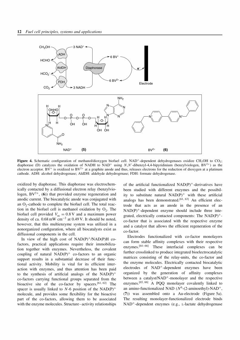
are more positive than −0.28 V (vs. SCE) at pH 8.5 canbe as high as 108 M−1 s−1, suggesting that the reactionsare diffusionally controlled. A biofuel cell was developedbased on enzymes (producing NADH upon the biocatalyticoxidation of primary substrate) and diaphorase (electricallycontacted via an electron relay and providing bioelectrocat-alytic oxidation of the NADH to NAD+, (5)).[60] A numberof NAD+-dependent enzymes (alcohol dehydrogenase, EC1.1.1.1; aldehyde dehydrogenase, EC 1.2.1.5; formate dehy-drogenase, EC 1.2.1.2) provided a sequence of biocatalyticreactions resulting in the oxidation of methanol to formalde-hyde and finally CO2 (Figure 4). The reduced co-factor(NADH) produced in all the steps was biocatalytically
12 Fuel cell principles, systems and applications
FDH
AldDH
ADH
CO2
HCHO
CH3OH
Diaphorase e−
Electrode3 NADH
3 NAD+
6 BV+
6 BV2+
HCO2−
O
H
OH
H
HOH
N+
NH2
O
H
O P O P O
OH OH H
O O
O
OH
H
OH
H
H
N
NN
N
NH2
NAD+ (5)
N+ N+
BV2+ (6)
Figure 4. Schematic configuration of methanol/dioxygen biofuel cell. NAD+-dependent dehydrogenases oxidize CH3OH to CO2;diaphorase (D) catalyzes the oxidation of NADH to NAD+ using N ,N ′-dibenzyl-4,4-bipyridinium (benzylviologen, BV2+) as theelectron acceptor. BV+ is oxidized to BV2+ at a graphite anode and thus, releases electrons for the reduction of dioxygen at a platinumcathode. ADH: alcohol dehydrogenase; AldDH: aldehyde dehydrogrnase; FDH: formate dehydrogenase.
oxidized by diaphorase. This diaphorase was electrochem-ically contacted by a diffusional electron relay (benzylvio-logen, BV2+, (6)) that provided enzyme regeneration andanodic current. The biocatalytic anode was conjugated withan O2-cathode to complete the biofuel cell. The total reac-tion in the biofuel cell is methanol oxidation by O2. Thebiofuel cell provided Voc = 0.8 V and a maximum powerdensity of ca. 0.68 mW cm−2 at 0.49 V. It should be noted,however, that this multienzyme system was utilized in anonorganized configuration, where all biocatalysts exist asdiffusional components in the cell.
In view of the high cost of NAD(P)+/NAD(P)H co-factors, practical applications require their immobiliza-tion together with enzymes. Nevertheless, the covalentcoupling of natural NAD(P)+ co-factors to an organicsupport results in a substantial decrease of their func-tional activity. Mobility is vital for its efficient inter-action with enzymes, and thus attention has been paidto the synthesis of artificial analogs of the NAD(P)+co-factors carrying functional groups separated from thebioactive site of the co-factor by spacers.[61, 62] Thespacer is usually linked to N -6 position of the NAD(P)+molecule, and provides some flexibility for the bioactivepart of the co-factors, allowing them to be associatedwith the enzyme molecules. Structure–activity relationships
of the artificial functionalized NAD(P)+-derivatives havebeen studied with different enzymes and the possibil-ity to substitute natural NAD(P)+ with these artificialanalogs has been demonstrated.[61, 63] An efficient elec-trode that acts as an anode in the presence of anNAD(P)+-dependent enzyme should include three inte-grated, electrically contacted components: The NAD(P)+-co-factor that is associated with the respective enzymeand a catalyst that allows the efficient regeneration of theco-factor.
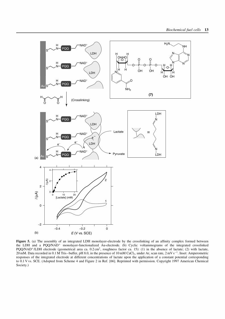
Electrodes functionalized with co-factor monolayerscan form stable affinity complexes with their respectiveenzymes.[64–66] These interfacial complexes can befurther crosslinked to produce integrated bioelectrocatalyticmatrices consisting of the relay-units, the co-factor andthe enzyme molecules. Electrically contacted biocatalyticelectrodes of NAD+-dependent enzymes have beenorganized by the generation of affinity complexesbetween a catalyst/NAD+-monolayer and the respectiveenzymes.[65, 66] A PQQ monolayer covalently linked toan amino-functionalized NAD (N6-(2-aminoethyl)-NAD+,(7)) was assembled onto a Au-electrode (Figure 5a).The resulting monolayer-functionalized electrode bindsNAD+-dependent enzymes (e.g., L-lactate dehydrogenase
Biochemical fuel cells 13
S
HN PQQ
NAD+
S
HN PQQ
NAD+
LDH
S
HN PQQ
NAD+
LDH
S
HN PQQ
NAD+
S
HN PQQ
NAD+
LDH
S
HN PQQ
NAD+
LDH
Pyruvate
Lactate
e–
e−e−
H
O
H
O(Crosslinking)
1
2
Au
Au
O
H
OH
H
HOH
N+
NH2
O
H
O P O P O
OH OH H
O
OH
H
OH
H
H
N
NN
N
(7)
O O
NHH2N
N
N
LDH
LDH
4
2
0
−2−0.4 −0.2 0
l (µA
)
l (µA
)
E (V vs. SCE)
4
2
00 10 20
[Lactate] (mM)
(b)
(a)
Figure 5. (a) The assembly of an integrated LDH monolayer-electrode by the crosslinking of an affinity complex formed betweenthe LDH and a PQQ/NAD+ monolayer-functionalized Au-electrode. (b) Cyclic voltammograms of the integrated crosslinkedPQQ/NAD+/LDH electrode (geometrical area ca. 0.2 cm2, roughness factor ca. 15): (1) in the absence of lactate; (2) with lactate,20 mM. Data recorded in 0.1 M Tris–buffer, pH 8.0, in the presence of 10 mM CaCl2, under Ar, scan rate, 2 mV s−1. Inset: Amperometricresponses of the integrated electrode at different concentrations of lactate upon the application of a constant potential correspondingto 0.1 V vs. SCE. (Adopted from Scheme 4 and Figure 2 in Ref. [66]. Reprinted with permission. Copyright 1997 American ChemicalSociety.)
14 Fuel cell principles, systems and applications
(LDH) EC 1.1.1.27) by affinity interactions between theco-factor and the biocatalyst. These enzyme electrodeselectrocatalyze the oxidation of their respective substrates(e.g., lactate). The crosslinking of the enzyme layer,using glutaric dialdehyde, generates a stable, electrically
contacted electrode. Figure 5(b) shows the electricalresponses of a crosslinked layered PQQ/NAD+/LDHelectrode in the absence (curve 1) and the presence(curve 2) of lactate, and the inset shows the respectivecalibration curve corresponding to the amperometric output
S NH2 S
HN
PQQPQQ
S
HN PQQ
GOx
Apo-GOxFAD
FADH2N
EDC
GOx
S
HN PQQ FAD
Glucose
Gluconicacid
e−e−
00 0.04 0.08
1
2
1
2
Au
Au Au
Au Au
O P O P O
O− O−H
O O
O
OH
H
OH
H
H
N
NN
N
NH
NH2
N
N
N
N
O
O
H HH OHH OHH OHH H
(8)
(8)
S
S
NH2
NH2
N
HNHO2C
O
O
CO2H
HO2C
(4)
400
200
0
−0.6 −0.2 0.2
l (µA
)
l (µA
)
E (V vs. SCE)
[Glucose] (mM)
(b)
(a)
Figure 6. (a) The surface-reconstitution of apo-GOx on a PQQ-FAD monolayer assembled on a Au-electrode (geometrical area ca.0.4 cm2, roughness factor ca. 20). (b) Cyclic voltammograms of the GOx-reconstituted PQQ-FAD-functionalized Au-electrode: (1)in the absence of glucose; (2) with glucose, 80 mM. Recorded in 0.1 M phosphate buffer, pH 7.0, under Ar, at 35 C, scan rate,5 mV s−1. Inset: Calibration curve corresponding to the current output (measured by chronoamperometry, E = 0.2 V vs. SCE) of thePQQ-FAD-reconstituted glucose oxidase enzyme-electrode at different concentrations of glucose. (Adopted from Scheme 1 and Figure 1in Ref. [71]. Reprinted with permission. Copyright 1996 American Chemical Society.)
Biochemical fuel cells 15
of the integrated LDH layered electrode at differentlactate concentrations. This system exemplifies a fullyintegrated rigid biocatalytic matrix composed of theenzyme, co-factor and catalyst. The complex betweenthe NAD+-co-factor and LDH aligns the enzyme onthe electrode support, thereby enabling effective electricalcommunication between the enzyme and the electrode,while the PQQ sites provide the regeneration of NAD+.
3.1.2 Flavoenzyme-functionalized electrodes asanode-elements: oxidation of glucose by GOxreconstituted on anFAD/PQQ-monolayer-functionalized electrode
The electrical contacting of redox enzymes that defydirect electrical communication with electrodes can beestablished by using synthetic or biologically active chargecarriers as intermediates between the redox center andthe electrode.[10] The overall electrical efficiency of anenzyme-modified electrode depends not only on the elec-tron transport properties of the mediator, but also on thetransfer steps occurring in the assembly. Diffusional elec-tron relays have been utilized to shuttle electrons betweenoxidative enzymes and anodes of biofuel cells, provid-ing the bioelectrocatalyzed oxidation of organic fuels (e.g.,methanol).[67–69] A sequence of biocatalytic reactions wasapplied to achieve the stepwise oxidation of methanol toCO2. In order to accomplish superior electron contacting,the mediator may be selectively placed in an optimum posi-tion between the redox center and the enzyme periphery. Inthe case of surface-confined enzymes, the orientation of theenzyme-mediator assembly with respect to the electrode canalso be optimized. A novel means for the establishment ofelectrical contact between the redox center of flavoenzymesand their environment based on a reconstitution approachhas recently been demonstrated.[70]
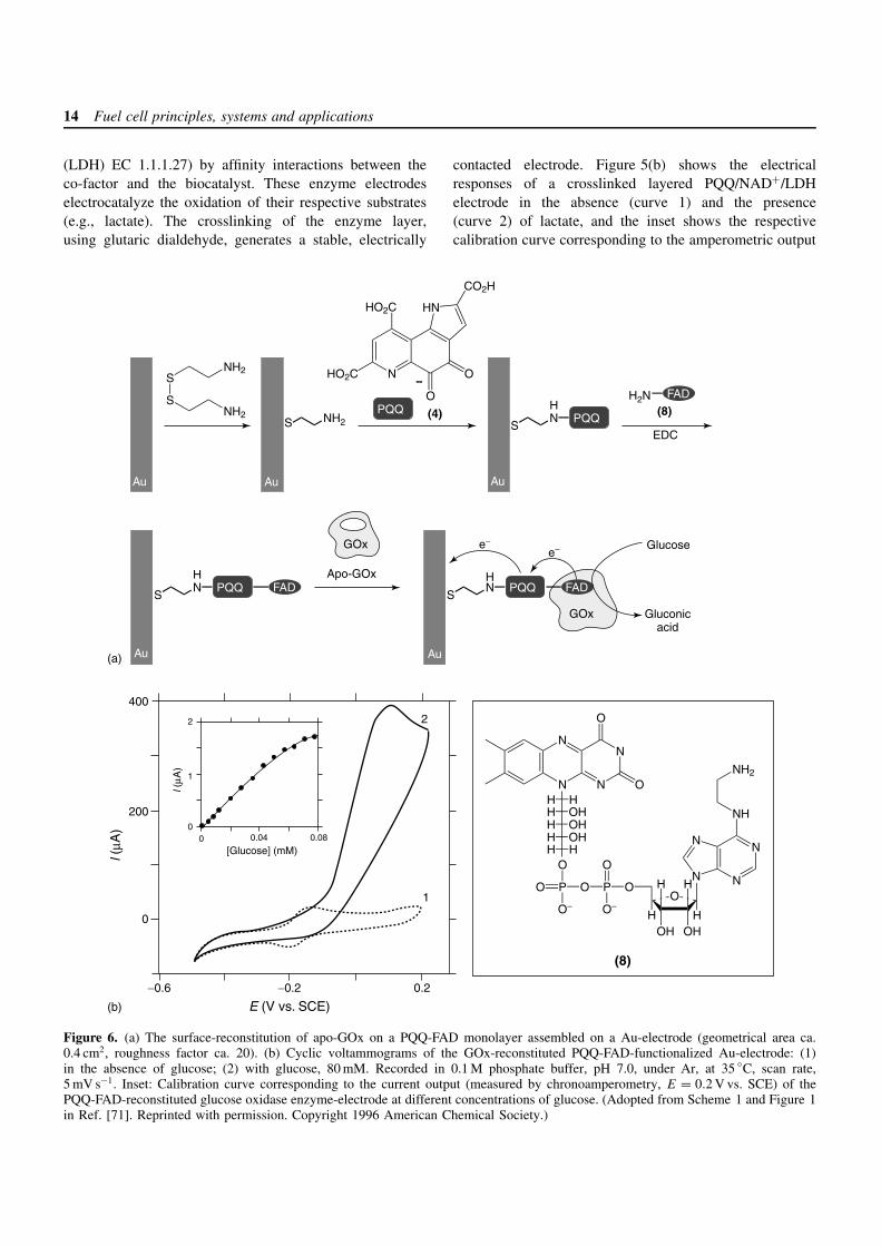
The organization of a reconstituted enzyme aligned onan electron relay-FAD monolayer was recently realizedby the reconstitution of apo-glucose oxidase (apo-GOx)on a surface functionalized with a relay-FAD monolayer(Figure 6a).[71, 72] PQQ (4) was covalently linked to abase cystamine monolayer at a Au-electrode, and N6-(2-aminoethyl)-FAD (8) was then attached to the PQQ relayunits. Apo-GOx (obtained by the extraction of the nativeFAD-co-factor from GOx (EC 1.1.3.4)) was then recon-stituted onto the FAD units of the PQQ-FAD-monolayerarchitecture to yield a structurally aligned, immobilized,biocatalyst on the electrode with a surface coverage of1.7 × 10−12 mol cm−2. The resulting enzyme-reconstitutedPQQ-FAD-functionalized electrode revealed bioelectrocat-alytic properties. Figure 6(b) shows cyclic voltammogramsof the enzyme electrode in the absence and the presence of
glucose (curves a and b, respectively). When the glucose-substrate is present, an electrocatalytic anodic current isobserved, implying electrical contact between the recon-stituted enzyme and the electrode surface. The electrodeconstantly oxidizes the PQQ site located at the proteinperiphery, and the PQQ-mediated oxidation of the FAD-center activates the bioelectrocatalytic oxidation of glucose(equations (15)–(17)). The resulting electrical current iscontrolled by the recycling rate of the reduced FAD bythe substrate. Figure 6(b), inset, shows the derived calibra-tion curve corresponding to the amperometric output of theenzyme-reconstituted electrode at different concentrationsof glucose. The resulting current densities are unprecedent-edly high (300 mA cm−2 at 80 mM of glucose).
FAD + glucose + 2H+ −−−→ FADH2
+ gluconic acid (15)
FADH2 + PQQ −−−→ FAD + PQQH2 (16)
PQQH2 −−−→ PQQ + 2H+
+ 2e−(to anode) (17)
Control experiments reveal that without the PQQ compo-nent, the system does not exhibit electron-transfer commu-nication with the electrode surface, demonstrating that thePQQ relay unit is, indeed, a key component in the electro-oxidation of glucose.[71, 72] The electron-transfer turnoverrate of GOx with molecular oxygen as the electron accep-tor is around 600 s−1 at 25 C. Using an activation energy of7.2 kcal mol−1, the electron-transfer turnover rate of GOx at35 C is estimated to be ca. 900 s−1.[71, 72] A densely packedmonolayer of GOx (ca. 1.7 × 10⁻¹² mol cm−2) that exhibitsthe theoretical electron-transfer turnover rate is expectedto yield an amperometric response of ca. 300 mA cm−2.This indicates that the reconstituted GOx on the PQQ-FAD monolayer exhibits an electron-transfer turnover withthe electrode of similar effectiveness to that observed forthe enzyme with oxygen as a natural electron acceptor.Indeed, the high current output of the resulting enzyme-electrode is preserved in the presence of O2 in the solu-tion.
3.2 Cathodes for biofuel cells based onenzyme-catalyzed reductive reactions
The biocatalytic reduction of oxidizers (e.g., dioxygen,hydrogen peroxide) has attracted much less attention thanthe biocatalytic oxidation of fuels. Nonetheless, in order toconstruct a biofuel cell element, it is essential to design afunctional cathode for the reduction of the oxidizer that iscoupled to the anode and allows the electrically balanced
16 Fuel cell principles, systems and applications
current flow. Conventional O2-reducing cathodes used infuel cells are usually not compatible with biocatalyticanodes since high temperatures and pressures are appliedfor their operation. Thus, biocatalytic reductive processesat the cathode should be considered as a strategy to designall biomaterial-based functional fuel cells.
3.2.1 Bioelectrocatalytic cathodes for the reductionof peroxides
Hydrogen peroxide is a strong oxidizer (E′ = 1.535 V vs.SCE), yet its electrochemical reduction proceeds with avery high overpotential. The bioelectrocatalyzed reductionof H2O2 has been accomplished in the presence of variousperoxidases (e.g., horseradish peroxidase, EC 1.11.1.7).[73]
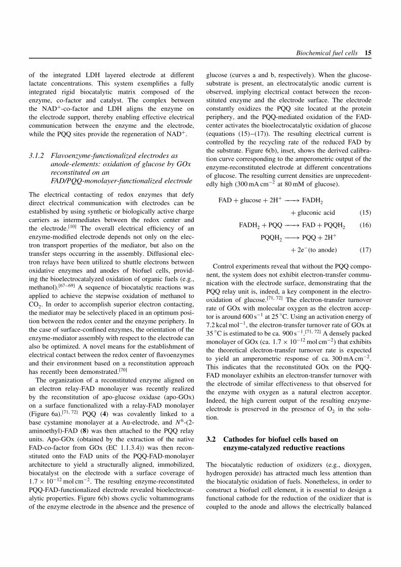
Microperoxidase-11 (MP-11, (9)) is an oligopeptideconsisting of 11 amino acids and a covalently linkedFe(III)-protoporphyrin IX heme site.[74] The oligopeptideis obtained by the controlled hydrolytic digestion ofcytochrome c and it corresponds to the active-sitemicroenvironment of the cytochrome. MP-11 revealsseveral advantages over usual peroxidases: It has a muchsmaller size, high stability and exhibits direct electricalcommunication with electrodes since its heme is exposedto the solution.
MP-11 was covalently linked to a cystamine mono-layer self-assembled on a Au-electrode.[75] The MP-11(9) structure suggests two different modes of couplingof the oligopeptide to the primary cystamine monolayer:(i) linkage of the carboxylic functions associated withthe protoporphyrin IX ligand to the monolayer interface;(ii) coupling of carboxylic acid residues of the oligopep-tide to the cystamine residues. These two modes of bind-ing reveal similar formal potentials – E
′ = −0.40 V vs.SCE (Figure 7a). The electron transfer rates of the two
binding modes of MP-11 were kinetically resolved usingchronoamperometry,[76] and appear in an approximately1 : 1 ratio. The interfacial electron transfer rates to the hemesites linked to the electrode by the two binding modes are8.5 and 16 s−1. Coulometric analysis of the MP-11 redoxwave, corresponding to the reversible reduction–oxidationof the heme (equation (18)), indicates a surface coverageof 2 × 10⁻¹⁰ mol cm−2.
[heme–Fe(III)] + e− −−−→ [heme–Fe(II)] (18)
Figure 7(b) shows cyclic voltammograms of the MP-11-functionalized electrode recorded at positive potentials inthe absence of H2O2 (curve 1) and in the presence of addedH2O2 (curve 2). The observed electrocatalytic cathodiccurrent indicates the effective electrobiocatalyzed reductionof H2O2 by the functionalized electrode. It should be notedthat the electrocatalytic current for the reduction of H2O2in aqueous solutions is observed at much more positivepotentials than the MP-11 redox potential registered inthe absence of H2O2 (cf. Figure 7a and b). The reasonfor this potential shift is the result of the formation ofthe Fe(IV) intermediate species in the presence of H2O2(equations (19)–(21)). Control experiments reveal that noelectroreduction of H2O2 occurs at the bare Au electrodewithin this potential window.
[heme–Fe(III)] + H2O2 −−−→ [heme–Fe(IV)=O]ž+ + H2O
(19)
[heme–Fe(IV)=O]ž+ + e−(from cathode) + H+
−−−→ [heme–Fe(IV)–OH] (20)
[heme–Fe(IV)–OH] + H+ + e−(from cathode)
−−−→ [heme–Fe(III)] + H2O (21)
60
40
20
0
−20
−40
−60−0.8 −0.6 −0.4 −0.2 0 0.2 −0.1 0 0.1 0.2 0.3 0.4
E (V vs. SCE) E (V vs. SCE)
l (µA
)
l (µA
)
20
10
0
−10
−20
−30
−40
−50
1
2
(a) (b)
Figure 7. (a) Cyclic voltammogram of the MP-11-modified Au-electrode (geometrical area ca. 0.2 cm2, roughness factor ca. 15)in 0.1 M phosphate buffer, pH 7.0, under Ar atmosphere, scan rate 50 mV s−1. (b) Cyclic voltammograms of the MP-11 modifiedelectrodes recorded at positive potentials in 0.1 M phosphate buffer, pH 7.0, scan rate 10 mV·s−1, (1) without H2O2, (2) in the presenceof 5 mM H2O2. (Adopted from Figure 3 and Figure 4 in Ref. [87]. Reproduced by permission of The Royal Society of Chemistry.)
Biochemical fuel cells 17
The biocatalytic reduction of oxidizers in nonaqueoussolutions immiscible with water is important since it canbe coupled to biocatalytic oxidative processes through liq-uid/liquid interfaces. Some enzymes,[77] particularly per-oxidases,[73] can function in nonaqueous solutions. A horse-radish peroxidase (HRP)-modified electrode has been app-lied for the biocatalytic reduction of organic peroxidesin nonaqueous solvents.[78] The biocatalytic activity ofenzymes, particularly of HRP,[79] however, is usually lower(sometimes by an order of magnitude) in organic solventsthan in water. MP-11 monolayer-modified electrodes havedemonstrated high activity and stability for the electrocat-alytic reduction of organic hydroperoxides in acetonitrileand ethanol.[80]
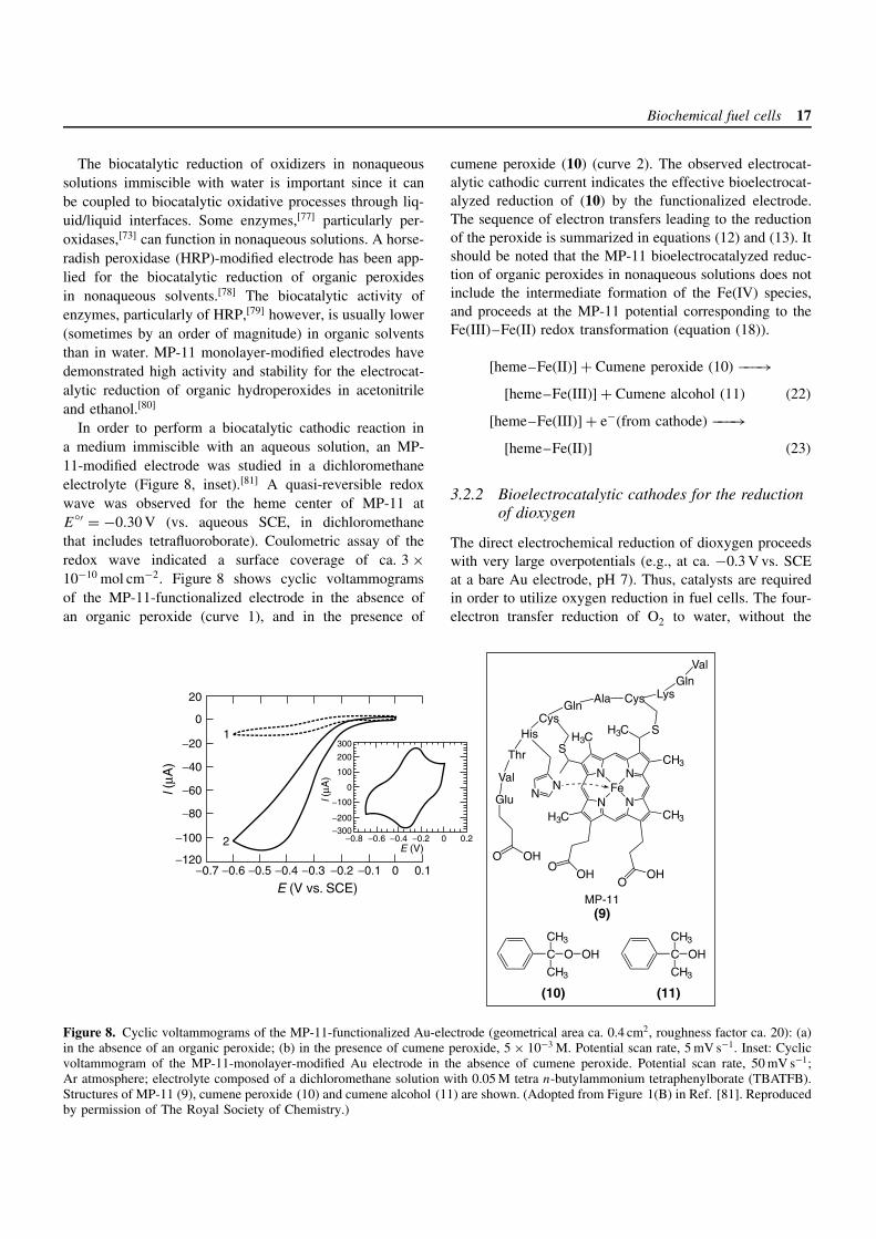
In order to perform a biocatalytic cathodic reaction ina medium immiscible with an aqueous solution, an MP-11-modified electrode was studied in a dichloromethaneelectrolyte (Figure 8, inset).[81] A quasi-reversible redoxwave was observed for the heme center of MP-11 atE
′ = −0.30 V (vs. aqueous SCE, in dichloromethanethat includes tetrafluoroborate). Coulometric assay of theredox wave indicated a surface coverage of ca. 3 ×10⁻¹⁰ mol cm−2. Figure 8 shows cyclic voltammogramsof the MP-11-functionalized electrode in the absence ofan organic peroxide (curve 1), and in the presence of
cumene peroxide (10) (curve 2). The observed electrocat-alytic cathodic current indicates the effective bioelectrocat-alyzed reduction of (10) by the functionalized electrode.The sequence of electron transfers leading to the reductionof the peroxide is summarized in equations (12) and (13). Itshould be noted that the MP-11 bioelectrocatalyzed reduc-tion of organic peroxides in nonaqueous solutions does notinclude the intermediate formation of the Fe(IV) species,and proceeds at the MP-11 potential corresponding to theFe(III)–Fe(II) redox transformation (equation (18)).
[heme–Fe(II)] + Cumene peroxide (10) −−−→[heme–Fe(III)] + Cumene alcohol (11) (22)
[heme–Fe(III)] + e−(from cathode) −−−→[heme–Fe(II)] (23)
3.2.2 Bioelectrocatalytic cathodes for the reductionof dioxygen
The direct electrochemical reduction of dioxygen proceedswith very large overpotentials (e.g., at ca. −0.3 V vs. SCEat a bare Au electrode, pH 7). Thus, catalysts are requiredin order to utilize oxygen reduction in fuel cells. The four-electron transfer reduction of O2 to water, without the
20
−20
−40
−60
−80
−100
−120
0
−0.7 −0.6 −0.5 −0.4 −0.3 −0.2 −0.1 0 0.1
E (V vs. SCE)
l (µA
)
l (µA
)
300
200
100
0
−100
−200
−300−0.8 −0.6 −0.4 −0.2 0.20
E (V)
1
2
C O OH
CH3
CH3
C OH
CH3
CH3
(10) (11)
MP-11(9)
GlnVal
OHO
Glu
Val
Thr
HisCys
GlnAla Cys Lys
NN
S
N
N
N
NFe
H3C CH3
OHO
OHO
H3CSH3C
CH3
Figure 8. Cyclic voltammograms of the MP-11-functionalized Au-electrode (geometrical area ca. 0.4 cm2, roughness factor ca. 20): (a)in the absence of an organic peroxide; (b) in the presence of cumene peroxide, 5 × 10⁻³ M. Potential scan rate, 5 mV s−1. Inset: Cyclicvoltammogram of the MP-11-monolayer-modified Au electrode in the absence of cumene peroxide. Potential scan rate, 50 mV s−1;Ar atmosphere; electrolyte composed of a dichloromethane solution with 0.05 M tetra n-butylammonium tetraphenylborate (TBATFB).Structures of MP-11 (9), cumene peroxide (10) and cumene alcohol (11) are shown. (Adopted from Figure 1(B) in Ref. [81]. Reproducedby permission of The Royal Society of Chemistry.)
18 Fuel cell principles, systems and applications
formation of peroxide or superoxide, is a major challengefor the future development of biofuel cell elements, sincesuch reactive intermediates would degrade the biocatalystsin the system.
Biocatalytic systems composed of enzymes and theirrespective electron transfer mediators (e.g., bilirubin oxi-dase, EC 1.3.3.5,[82] or fungal laccase, EC 1.10.3.2,[83]
with 2,2′-azino-bis-(3-ethylbenzothiazoline-6-sulfonate) asa mediator) are able to biocatalyze the electroreduction ofO2 to H2O effectively at ca. 0.4 V (vs. SCE), significantlydecreasing the overpotential. These systems, however, arecomposed of dissolved enzymes and mediators operatingvia a diffusional path that is unacceptable for technolog-ical applications. Organized layered enzyme systems aremuch more promising for their use in biocatalytic cathodes.
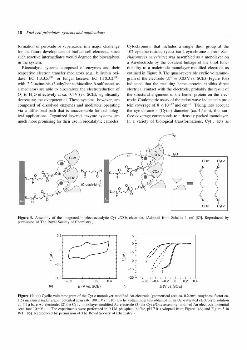
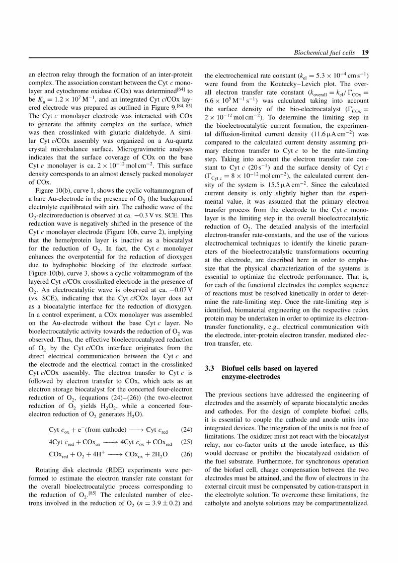
Cytochrome c that includes a single thiol group at the102-cysteine-residue (yeast iso-2-cytochrome c from Sac-charomyces cerevisiae) was assembled as a monolayer ona Au-electrode by the covalent linkage of the thiol func-tionality to a maleimide monolayer-modified electrode asoutlined in Figure 9. The quasi-reversible cyclic voltammo-gram of the electrode (E′ = 0.03 V vs. SCE) (Figure 10a)indicated that the resulting heme–protein exhibits directelectrical contact with the electrode, probably the result ofthe structural alignment of the heme–protein on the elec-trode. Coulometric assay of the redox wave indicated a pro-tein coverage of 8 × 10⁻¹² mol cm−2. Taking into accountthe cytochrome c (Cyt c) diameter (ca. 4.5 nm), this sur-face coverage corresponds to a densely packed monolayer.In a variety of biological transformations, Cyt c acts as
COx
COx
COx
COx
e−
e−
H
O
H
O
(Crosslinking)
O2
S NH
O NO
O Cys
Cyt c
S
S NH
O NO
O Cys
Cyt c
S
S NH
O NO
O Cys
Cyt c
S
S NH
O NO
O Cys
Cyt c
S
Au Au
N
N
COx
COx
N
N
Cyt c
Cyt c
H2O
Figure 9. Assembly of the integrated bioelectrocatalytic Cyt c/COx-electrode. (Adopted from Scheme 4, ref. [85]. Reproduced bypermission of The Royal Society of Chemistry.)
0.5
0
−0.5
−1.0−0.2 0 0.2 0.4
l (µA
)
l (µA
)
E (V vs. SCE) E (V vs. SCE)
5
0
−5
−10
−15
−20−0.6 −0.4 −0.2 0 0.2 0.4
(a) (b)
2
1 3
Figure 10. (a) Cyclic voltammogram of the Cyt c monolayer-modified Au-electrode (geometrical area ca. 0.2 cm2, roughness factor ca.1.5) measured under argon, potential scan rate 100 mV s−1. (b) Cyclic voltammograms obtained in an O2 -saturated electrolyte solutionat: (1) a bare Au-electrode; (2) the Cyt c monolayer-modified Au-electrode (3) the Cyt c/Cox assembly modified Au-electrode; potentialscan rate 10 mV s−1. The experiments were performed in 0.1 M phosphate buffer, pH 7.0. (Adopted from Figure 1(A) and Figure 5 inRef. [85]. Reproduced by permission of The Royal Society of Chemistry.)
Biochemical fuel cells 19
an electron relay through the formation of an inter-proteincomplex. The association constant between the Cyt c mono-layer and cytochrome oxidase (COx) was determined[64] tobe Ka = 1.2 × 10⁷ M−1, and an integrated Cyt c/COx lay-ered electrode was prepared as outlined in Figure 9.[84, 85]
The Cyt c monolayer electrode was interacted with COxto generate the affinity complex on the surface, whichwas then crosslinked with glutaric dialdehyde. A simi-lar Cyt c/COx assembly was organized on a Au-quartzcrystal microbalance surface. Microgravimetric analysesindicates that the surface coverage of COx on the baseCyt c monolayer is ca. 2 × 10⁻¹² mol cm−2. This surfacedensity corresponds to an almost densely packed monolayerof COx.
Figure 10(b), curve 1, shows the cyclic voltammogram ofa bare Au-electrode in the presence of O2 (the backgroundelectrolyte equilibrated with air). The cathodic wave of theO2-electroreduction is observed at ca. −0.3 V vs. SCE. Thisreduction wave is negatively shifted in the presence of theCyt c monolayer electrode (Figure 10b, curve 2), implyingthat the heme/protein layer is inactive as a biocatalystfor the reduction of O2. In fact, the Cyt c monolayerenhances the overpotential for the reduction of dioxygendue to hydrophobic blocking of the electrode surface.Figure 10(b), curve 3, shows a cyclic voltammogram of thelayered Cyt c/COx crosslinked electrode in the presence ofO2. An electrocatalytic wave is observed at ca. −0.07 V(vs. SCE), indicating that the Cyt c/COx layer does actas a biocatalytic interface for the reduction of dioxygen.In a control experiment, a COx monolayer was assembledon the Au-electrode without the base Cyt c layer. Nobioelectrocatalytic activity towards the reduction of O2 wasobserved. Thus, the effective bioelectrocatalyzed reductionof O2 by the Cyt c/COx interface originates from thedirect electrical communication between the Cyt c andthe electrode and the electrical contact in the crosslinkedCyt c/COx assembly. The electron transfer to Cyt c isfollowed by electron transfer to COx, which acts as anelectron storage biocatalyst for the concerted four-electronreduction of O2, (equations (24)–(26)) (the two-electronreduction of O2 yields H2O2, while a concerted four-electron reduction of O2 generates H2O).
Cyt cox + e−(from cathode) −−−→ Cyt cred (24)
4Cyt cred + COxox −−−→ 4Cyt cox + COxred (25)
COxred + O2 + 4H+ −−−→ COxox + 2H2O (26)
Rotating disk electrode (RDE) experiments were per-formed to estimate the electron transfer rate constant forthe overall bioelectrocatalytic process corresponding tothe reduction of O2.[85] The calculated number of elec-trons involved in the reduction of O2 (n = 3.9 ± 0.2) and
the electrochemical rate constant (kel = 5.3 × 10⁻⁴ cm s−1)were found from the Koutecky–Levich plot. The over-all electron transfer rate constant (koverall = kel/COx =6.6 × 10⁵ M−1 s−1) was calculated taking into accountthe surface density of the bio-electrocatalyst (COx =2 × 10⁻¹² mol cm−2). To determine the limiting step inthe bioelectrocatalytic current formation, the experimen-tal diffusion-limited current density (11.6 µA cm−2) wascompared to the calculated current density assuming pri-mary electron transfer to Cyt c to be the rate-limitingstep. Taking into account the electron transfer rate con-stant to Cyt c (20 s−1) and the surface density of Cyt c
(Cyt c = 8 × 10⁻¹² mol cm−2), the calculated current den-sity of the system is 15.5 µA cm−2. Since the calculatedcurrent density is only slightly higher than the experi-mental value, it was assumed that the primary electrontransfer process from the electrode to the Cyt c mono-layer is the limiting step in the overall bioelectrocatalyticreduction of O2. The detailed analysis of the interfacialelectron-transfer rate-constants, and the use of the variouselectrochemical techniques to identify the kinetic param-eters of the bioelectrocatalytic transformations occurringat the electrode, are described here in order to empha-size that the physical characterization of the systems isessential to optimize the electrode performance. That is,for each of the functional electrodes the complex sequenceof reactions must be resolved kinetically in order to deter-mine the rate-limiting step. Once the rate-limiting step isidentified, biomaterial engineering on the respective redoxprotein may be undertaken in order to optimize its electron-transfer functionality, e.g., electrical communication withthe electrode, inter-protein electron transfer, mediated elec-tron transfer, etc.
3.3 Biofuel cells based on layeredenzyme-electrodes
The previous sections have addressed the engineering ofelectrodes and the assembly of separate biocatalytic anodesand cathodes. For the design of complete biofuel cells,it is essential to couple the cathode and anode units intointegrated devices. The integration of the units is not free oflimitations. The oxidizer must not react with the biocatalystrelay, nor co-factor units at the anode interface, as thiswould decrease or prohibit the biocatalyzed oxidation ofthe fuel substrate. Furthermore, for synchronous operationof the biofuel cell, charge compensation between the twoelectrodes must be attained, and the flow of electrons in theexternal circuit must be compensated by cation-transport inthe electrolyte solution. To overcome these limitations, thecatholyte and anolyte solutions may be compartmentalized.
20 Fuel cell principles, systems and applications
Alternatively, the bioelectrocatalytic transformations at theelectrodes may be driven efficiently enough that interferingcomponents do not perturb the cell operation. In anybiofuel cell, either the bioelectrocatalytic transformationsor the transport process is a rate-limiting step controllingthe cell efficiency. The mechanistic characterization andunderstanding of the biofuel cell performance is thereforeimportant as it provides a means for the further optimizationof the cell efficiency.
3.3.1 A biofuel cell based on PQQ and MP-11monolayer-functionalized electrodes
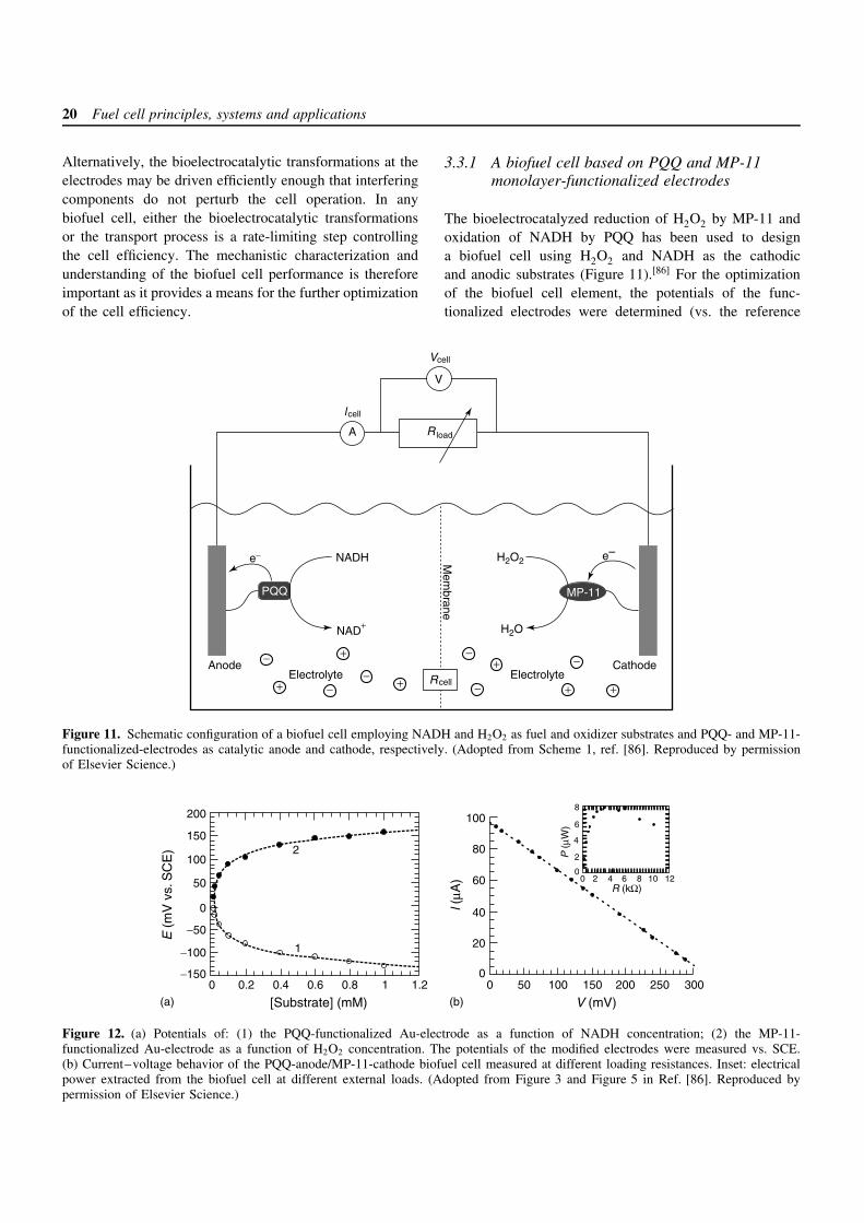
The bioelectrocatalyzed reduction of H2O2 by MP-11 andoxidation of NADH by PQQ has been used to designa biofuel cell using H2O2 and NADH as the cathodicand anodic substrates (Figure 11).[86] For the optimizationof the biofuel cell element, the potentials of the func-tionalized electrodes were determined (vs. the reference
PQQ
e− H2O2
H2O
Anode Cathode
e–
Mem
brane
Electrolyte Electrolyte
V
A
Vcell
l cell
Rcell
MP-11
NADH
NAD+
Rload
−
−+
+
+
+
+ +−
−
−
−
Figure 11. Schematic configuration of a biofuel cell employing NADH and H2O2 as fuel and oxidizer substrates and PQQ- and MP-11-functionalized-electrodes as catalytic anode and cathode, respectively. (Adopted from Scheme 1, ref. [86]. Reproduced by permissionof Elsevier Science.)
200 100
80
60
40
20
0
150
100
50
−50
−100
−150
0
0 0.2 0.4 0.6 0.8 1 1.2 0 50 100 150 200 250 300
E (
mV
vs.
SC
E)
l (µA
)
[Substrate] (mM) V (mV)
1
2
(a) (b)
8
6
4
2
00 2 4 6 8 10 12
R (kΩ)
P (
µW)
Figure 12. (a) Potentials of: (1) the PQQ-functionalized Au-electrode as a function of NADH concentration; (2) the MP-11-functionalized Au-electrode as a function of H2O2 concentration. The potentials of the modified electrodes were measured vs. SCE.(b) Current–voltage behavior of the PQQ-anode/MP-11-cathode biofuel cell measured at different loading resistances. Inset: electricalpower extracted from the biofuel cell at different external loads. (Adopted from Figure 3 and Figure 5 in Ref. [86]. Reproduced bypermission of Elsevier Science.)
Biochemical fuel cells 21
electrode, SCE) as a function of the cathodic and anodicsubstrate concentrations. Figure 12(a) shows the poten-tial of the PQQ-electrode at different concentrations ofNADH (curve 1) and the potential of the MP-11-electrodeat different H2O2 concentrations (curve 2). The poten-tials of the PQQ monolayer-electrode and the MP-11-functionalized electrode are negatively shifted and posi-tively shifted as the concentrations of NADH and H2O2are elevated, respectively. The potentials of the electrodesreveal Nernstian-type behavior reaching saturation at highsubstrate concentrations (ca. 1 × 10⁻³ M). From the satura-tion potential values of the PQQ- and MP-11-functionalizedelectrodes, an open-circuit voltage of the cell of ca. 0.3 Vwas estimated. Taking into account the surface density ofthe catalysts (1.2 × 10⁻¹⁰ and 2 × 10⁻¹⁰ mol cm−2 for PQQand MP-11, respectively), their interfacial electron trans-fer rate constants (ca. 8 and 14 s−1 for PQQ and MP-11,respectively) and the number of electrons participating ina single electron transfer event (2 and 1 for PQQ and MP-11, respectively), one may derive the theoretical limit of thecurrent densities that can be extracted by the catalyticallyactive electrodes (ca. 185 and 270 µA cm−2 for the PQQand MP-11 electrodes, respectively).
The biofuel cell performance was examined at 1 ×10⁻³ M of each of the fuel and oxidizer. The cell volt-age rose upon increasing the external load resistance andlevels off to a constant value of ca. 310 mV at ca. 50 k.Upon an increase of the load resistance, the cell cur-rent dropped and reached almost zero at a resistance ofca. 50 k. Figure 12(b) shows the current–voltage behav-ior of the biofuel cell at different external loads. The cellyields a short-circuit current (Isc) and open-circuit volt-age (Voc) of ca. 100 µA and 310 mV, respectively. Theshort-circuit current density was ca. 30 µA cm−2, which isalmost one order of magnitude less than the theoreticallimits for the catalyst-modified electrodes. Thus, the inter-facial kinetics of the biocatalyzed transformations at theelectrodes is probably not the current-limiting step. Thepower extracted from the biofuel cell (Pcell = VcellIcell) isshown in Figure 12(b), inset, for different external loads,and reaches a maximum of 8 µW at an external load of3 k. The ideal voltage–current relationship for an electro-chemical generator of electricity is rectangular. The lineardependence observed for this biofuel cell has a significantdeviation from the ideal behavior and yields a fill fac-tor of the biofuel cell of f ≈ 0.25 (equation (27)). Thisdeviation from the ideal rectangular Vcell –Icell relationshipresults from mass transport losses reducing the cell voltagebelow its reversible thermodynamic value. It should alsobe noted that in this study NADH is used as the fuel. In areal biofuel cell, NADH should be generated in situ from anabundant substrate and the corresponding NAD+-dependent
dehydrogenase (e.g., alcohol or lactate acid in the presenceof alcohol dehydrogenase or LDH, respectively).
f = Pcell × I−1sc × V −1
oc (27)
3.3.2 Biofuel cells based on GOx and MP-11monolayer-functionalized electrodes
The bioelectrocatalyzed reduction of H2O2 by the MP-11monolayer electrode, and the oxidation of glucose by thereconstituted GOx-monolayer electrode allow us to designbiofuel cells using H2O2 and glucose as the cathodicand anodic substrates (Figure 13).[87] Figure 14(a) showsthe potentials of the GOx monolayer electrode at differ-ent concentrations of glucose (curve 1) and the poten-tials of the MP-11 monolayer electrode at different con-centrations of H2O2 (curve 2). The potentials of theGOx monolayer electrode and of the MP-11 monolayerelectrode are negatively shifted and positively shifted asthe concentrations of the glucose and H2O2 are ele-vated, respectively. The potentials of the electrodes revealNernstian-type behavior, reaching saturation at high sub-strate concentrations of ca. 1 × 10⁻³ M. From the saturatedpotential values of the GOx and MP-11 monolayer elec-trodes, the theoretical limit of the open-circuit voltageof the cell is estimated to be ca. 320 mV. The short-circuit current (Isc) generated by the cell is 340 µA. Takinginto account the geometrical electrode area (0.2 cm2) andthe electrode roughness factor (ca. 15), the current gener-ated by the cell can be translated into a current densityof ca. 114 µA cm−2. The theoretical limit of the currentdensity extractable from the MP-11 monolayer electrodeis ca. 270 µA cm−2 (surface coverage × interfacial electrontransfer rate × Faraday constant). For the GOx monolayerelectrode the maximum extractable current density wasestimated to be ca. 200 µA cm−2 based on the surfacecoverage of the reconstituted GOx (1.7 × 10⁻¹² mol cm−2)and the turnover rate of the enzyme (ca. 600 s−1). Thus,the observed short-circuit current density of the cellis probably controlled and limited by the bioelectrocat-alyzed oxidation of glucose. This suggests that increas-ing the GOx content associated with the electrode couldenhance the current density and the extractable power fromthe cell.
The biofuel cell performance was examined at concen-trations of 1 × 10⁻³ M of each substrate. The cell voltageincreases as the external load resistance is elevated, andat an external load of ca. 50 k, it levels off to a con-stant value of ca. 310 mV. Upon increasing the externalload, the current drops and is almost zero at an externalload of 100 k. Figure 14(b) shows the current–voltagebehavior of the biofuel cell at different external loads.The linear dependence observed for the biofuel cell has
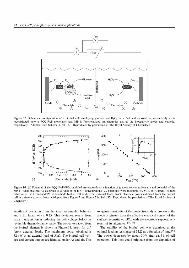
22 Fuel cell principles, systems and applications
GOx
FADPQQ
Glucose
Gluconicacid
e− e− H2O2
H2O
Anode Cathode
e−
Mem
brane
Electrolyte ElectrolyteRcell
MP-11
Rload
Vcell
lcell
V
A
+
+
+
+
+ +
−
−−
−
−
−
Figure 13. Schematic configuration of a biofuel cell employing glucose and H2O2 as a fuel and an oxidizer, respectively. GOxreconstituted onto a PQQ-FAD-monolayer and MP-11-functionalized Au-electrodes act as the biocatalytic anode and cathode,respectively. (Adopted from Scheme 3, ref. [87]. Reproduced by permission of The Royal Society of Chemistry.)
200
150
100
50
−50
−100
−150
0
0 0.2 0.4 0.6 0.8 1 1.2
[Substrate] (mM)
E (
mV
vs.
SC
E)
40
20
0
0 5 10
R (kΩ)
Pow
er (
µW)
400
300
200
100
00 100 200 300 400
Vcell (mV)
I cel
l (µA
)
(a) (b)
2
1
Figure 14. (a) Potential of the PQQ-FAD/GOx-modified Au-electrode as a function of glucose concentrations (1) and potential of theMP-11-functionalized Au-electrode as a function of H2O2 concentrations (2), potentials were measured vs. SCE. (b) Current–voltagebehavior of the GOx-anode/MP-11-cathode biofuel cell at different external loads. Inset: electrical power extracted from the biofuelcell at different external loads. (Adopted from Figure 5 and Figure 7 in Ref. [87]. Reproduced by permission of The Royal Society ofChemistry.)
significant deviation from the ideal rectangular behaviorand a fill factor of ca. 0.25. This deviation results frommass transport losses reducing the cell voltage below itsreversible thermodynamic value. The power extracted fromthe biofuel element is shown in Figure 14, inset, for dif-ferent external loads. The maximum power obtained is32 µW at an external load of 3 k. The biofuel cell volt-age and current outputs are identical under Ar and air. This
oxygen-insensitivity of the bioelectrocatalytic process at theanode originates from the effective electrical contact of thesurface-reconstituted GOx with the electrode support, as aresult of its alignment.[71, 72]
The stability of the biofuel cell was examined at theoptimal loading resistance of 3 k as a function of time.[87]
The power decreases by about 50% after ca. 3 h of celloperation. This loss could originate from the depletion of
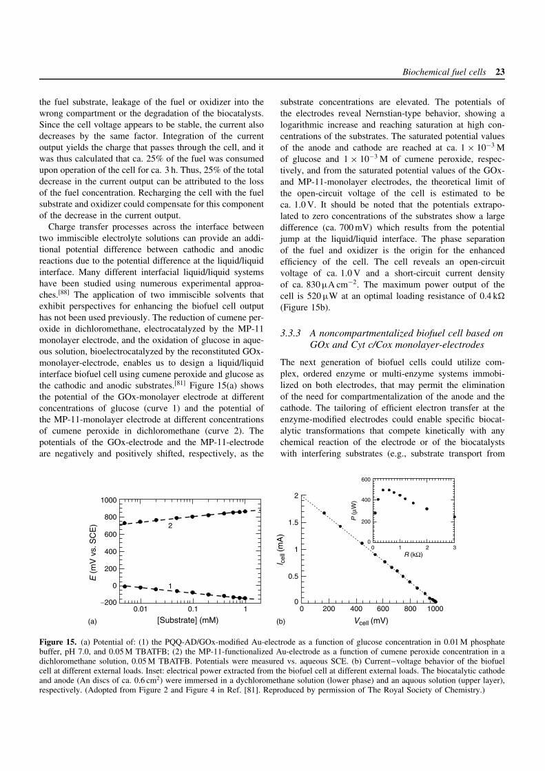
Biochemical fuel cells 23
the fuel substrate, leakage of the fuel or oxidizer into thewrong compartment or the degradation of the biocatalysts.Since the cell voltage appears to be stable, the current alsodecreases by the same factor. Integration of the currentoutput yields the charge that passes through the cell, and itwas thus calculated that ca. 25% of the fuel was consumedupon operation of the cell for ca. 3 h. Thus, 25% of the totaldecrease in the current output can be attributed to the lossof the fuel concentration. Recharging the cell with the fuelsubstrate and oxidizer could compensate for this componentof the decrease in the current output.
Charge transfer processes across the interface betweentwo immiscible electrolyte solutions can provide an addi-tional potential difference between cathodic and anodicreactions due to the potential difference at the liquid/liquidinterface. Many different interfacial liquid/liquid systemshave been studied using numerous experimental approa-ches.[88] The application of two immiscible solvents thatexhibit perspectives for enhancing the biofuel cell outputhas not been used previously. The reduction of cumene per-oxide in dichloromethane, electrocatalyzed by the MP-11monolayer electrode, and the oxidation of glucose in aque-ous solution, bioelectrocatalyzed by the reconstituted GOx-monolayer-electrode, enables us to design a liquid/liquidinterface biofuel cell using cumene peroxide and glucose asthe cathodic and anodic substrates.[81] Figure 15(a) showsthe potential of the GOx-monolayer electrode at differentconcentrations of glucose (curve 1) and the potential ofthe MP-11-monolayer electrode at different concentrationsof cumene peroxide in dichloromethane (curve 2). Thepotentials of the GOx-electrode and the MP-11-electrodeare negatively and positively shifted, respectively, as the
substrate concentrations are elevated. The potentials ofthe electrodes reveal Nernstian-type behavior, showing alogarithmic increase and reaching saturation at high con-centrations of the substrates. The saturated potential valuesof the anode and cathode are reached at ca. 1 × 10⁻³ Mof glucose and 1 × 10⁻³ M of cumene peroxide, respec-tively, and from the saturated potential values of the GOx-and MP-11-monolayer electrodes, the theoretical limit ofthe open-circuit voltage of the cell is estimated to beca. 1.0 V. It should be noted that the potentials extrapo-lated to zero concentrations of the substrates show a largedifference (ca. 700 mV) which results from the potentialjump at the liquid/liquid interface. The phase separationof the fuel and oxidizer is the origin for the enhancedefficiency of the cell. The cell reveals an open-circuitvoltage of ca. 1.0 V and a short-circuit current densityof ca. 830 µA cm−2. The maximum power output of thecell is 520 µW at an optimal loading resistance of 0.4 k
(Figure 15b).
3.3.3 A noncompartmentalized biofuel cell based onGOx and Cyt c/Cox monolayer-electrodes
The next generation of biofuel cells could utilize com-plex, ordered enzyme or multi-enzyme systems immobi-lized on both electrodes, that may permit the eliminationof the need for compartmentalization of the anode and thecathode. The tailoring of efficient electron transfer at theenzyme-modified electrodes could enable specific biocat-alytic transformations that compete kinetically with anychemical reaction of the electrode or of the biocatalystswith interfering substrates (e.g., substrate transport from
1000
800
600
400
200
0
0.01 0.1 1−200
2
1
[Substrate] (mM)
E (
mV
vs.
SC
E)
2
1.5
1
0.5
00 200 400 600 800 1000
l cel
l (m
A)
Vcell (mV)
600
400
200
00 1 2 3
R (kΩ)
P (
µW)
(a) (b)
Figure 15. (a) Potential of: (1) the PQQ-AD/GOx-modified Au-electrode as a function of glucose concentration in 0.01 M phosphatebuffer, pH 7.0, and 0.05 M TBATFB; (2) the MP-11-functionalized Au-electrode as a function of cumene peroxide concentration in adichloromethane solution, 0.05 M TBATFB. Potentials were measured vs. aqueous SCE. (b) Current–voltage behavior of the biofuelcell at different external loads. Inset: electrical power extracted from the biofuel cell at different external loads. The biocatalytic cathodeand anode (An discs of ca. 0.6 cm2) were immersed in a dychloromethane solution (lower phase) and an aquous solution (upper layer),respectively. (Adopted from Figure 2 and Figure 4 in Ref. [81]. Reproduced by permission of The Royal Society of Chemistry.)
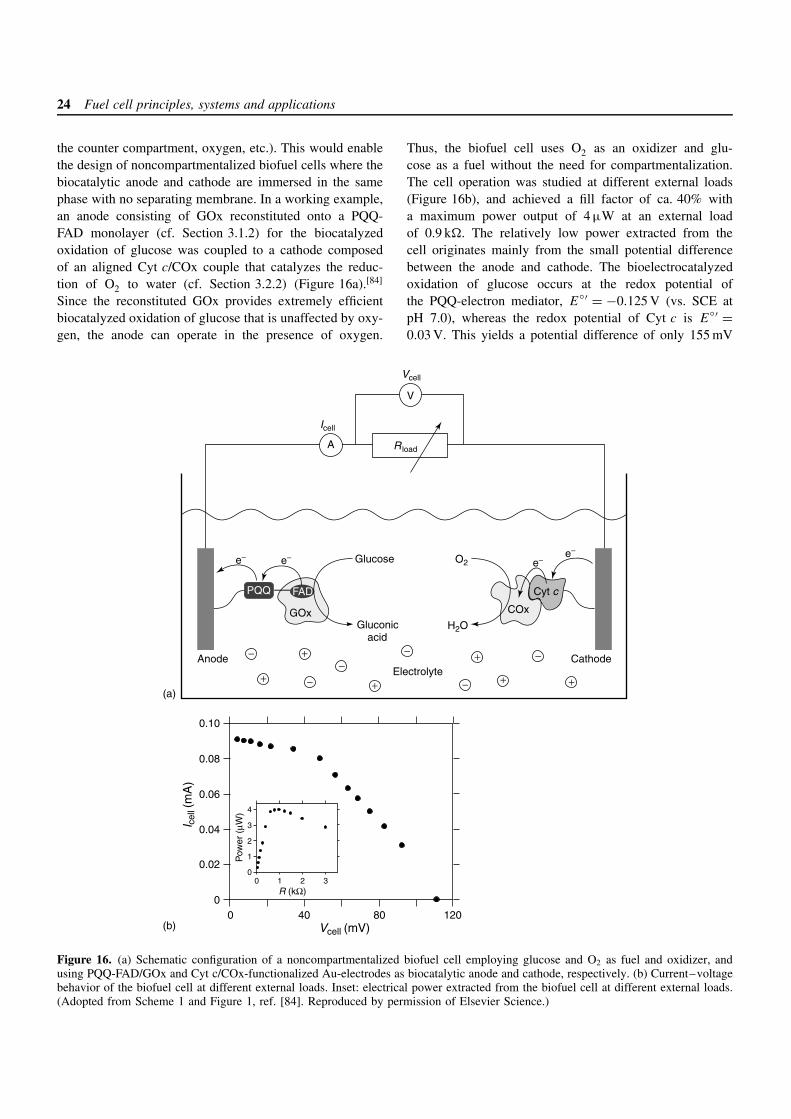
24 Fuel cell principles, systems and applications
the counter compartment, oxygen, etc.). This would enablethe design of noncompartmentalized biofuel cells where thebiocatalytic anode and cathode are immersed in the samephase with no separating membrane. In a working example,an anode consisting of GOx reconstituted onto a PQQ-FAD monolayer (cf. Section 3.1.2) for the biocatalyzedoxidation of glucose was coupled to a cathode composedof an aligned Cyt c/COx couple that catalyzes the reduc-tion of O2 to water (cf. Section 3.2.2) (Figure 16a).[84]
Since the reconstituted GOx provides extremely efficientbiocatalyzed oxidation of glucose that is unaffected by oxy-gen, the anode can operate in the presence of oxygen.
Thus, the biofuel cell uses O2 as an oxidizer and glu-cose as a fuel without the need for compartmentalization.The cell operation was studied at different external loads(Figure 16b), and achieved a fill factor of ca. 40% witha maximum power output of 4 µW at an external loadof 0.9 k. The relatively low power extracted from thecell originates mainly from the small potential differencebetween the anode and cathode. The bioelectrocatalyzedoxidation of glucose occurs at the redox potential ofthe PQQ-electron mediator, E
′ = −0.125 V (vs. SCE atpH 7.0), whereas the redox potential of Cyt c is E
′ =0.03 V. This yields a potential difference of only 155 mV
GOx
FADPQQ
Glucose
Gluconicacid
e− e− O2
H2O
Anode Cathode
e−
Electrolyte
Vcell
Icell
COx
Cyt c
e−
V
A Rload
−
−−
−
−
−
+
+
+
+
+ +
0.10
0.08
0.06
0.04
0.02
00 40 80 120
I cel
l (m
A)
Vcell (mV)
4
3
2
1
00 1 2 3
R (kΩ)
Pow
er (
µW)
(b)
(a)
Figure 16. (a) Schematic configuration of a noncompartmentalized biofuel cell employing glucose and O2 as fuel and oxidizer, andusing PQQ-FAD/GOx and Cyt c/COx-functionalized Au-electrodes as biocatalytic anode and cathode, respectively. (b) Current–voltagebehavior of the biofuel cell at different external loads. Inset: electrical power extracted from the biofuel cell at different external loads.(Adopted from Scheme 1 and Figure 1, ref. [84]. Reproduced by permission of Elsevier Science.)
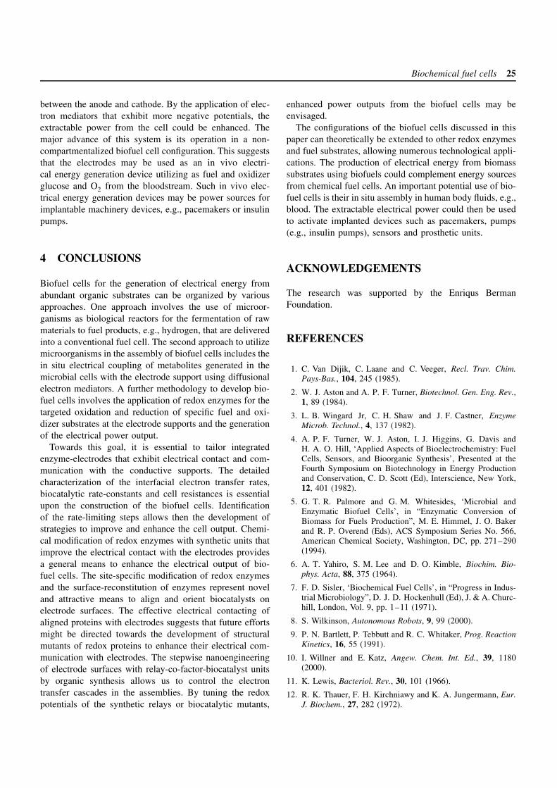
Biochemical fuel cells 25
between the anode and cathode. By the application of elec-tron mediators that exhibit more negative potentials, theextractable power from the cell could be enhanced. Themajor advance of this system is its operation in a non-compartmentalized biofuel cell configuration. This suggeststhat the electrodes may be used as an in vivo electri-cal energy generation device utilizing as fuel and oxidizerglucose and O2 from the bloodstream. Such in vivo elec-trical energy generation devices may be power sources forimplantable machinery devices, e.g., pacemakers or insulinpumps.
4 CONCLUSIONS
Biofuel cells for the generation of electrical energy fromabundant organic substrates can be organized by variousapproaches. One approach involves the use of microor-ganisms as biological reactors for the fermentation of rawmaterials to fuel products, e.g., hydrogen, that are deliveredinto a conventional fuel cell. The second approach to utilizemicroorganisms in the assembly of biofuel cells includes thein situ electrical coupling of metabolites generated in themicrobial cells with the electrode support using diffusionalelectron mediators. A further methodology to develop bio-fuel cells involves the application of redox enzymes for thetargeted oxidation and reduction of specific fuel and oxi-dizer substrates at the electrode supports and the generationof the electrical power output.
Towards this goal, it is essential to tailor integratedenzyme-electrodes that exhibit electrical contact and com-munication with the conductive supports. The detailedcharacterization of the interfacial electron transfer rates,biocatalytic rate-constants and cell resistances is essentialupon the construction of the biofuel cells. Identificationof the rate-limiting steps allows then the development ofstrategies to improve and enhance the cell output. Chemi-cal modification of redox enzymes with synthetic units thatimprove the electrical contact with the electrodes providesa general means to enhance the electrical output of bio-fuel cells. The site-specific modification of redox enzymesand the surface-reconstitution of enzymes represent noveland attractive means to align and orient biocatalysts onelectrode surfaces. The effective electrical contacting ofaligned proteins with electrodes suggests that future effortsmight be directed towards the development of structuralmutants of redox proteins to enhance their electrical com-munication with electrodes. The stepwise nanoengineeringof electrode surfaces with relay-co-factor-biocatalyst unitsby organic synthesis allows us to control the electrontransfer cascades in the assemblies. By tuning the redoxpotentials of the synthetic relays or biocatalytic mutants,
enhanced power outputs from the biofuel cells may beenvisaged.
The configurations of the biofuel cells discussed in thispaper can theoretically be extended to other redox enzymesand fuel substrates, allowing numerous technological appli-cations. The production of electrical energy from biomasssubstrates using biofuels could complement energy sourcesfrom chemical fuel cells. An important potential use of bio-fuel cells is their in situ assembly in human body fluids, e.g.,blood. The extractable electrical power could then be usedto activate implanted devices such as pacemakers, pumps(e.g., insulin pumps), sensors and prosthetic units.
ACKNOWLEDGEMENTS
The research was supported by the Enriqus BermanFoundation.
REFERENCES
1. C. Van Dijik, C. Laane and C. Veeger, Recl. Trav. Chim.Pays-Bas., 104, 245 (1985).
2. W. J. Aston and A. P. F. Turner, Biotechnol. Gen. Eng. Rev.,1, 89 (1984).
3. L. B. Wingard Jr, C. H. Shaw and J. F. Castner, EnzymeMicrob. Technol., 4, 137 (1982).
4. A. P. F. Turner, W. J. Aston, I. J. Higgins, G. Davis andH. A. O. Hill, ‘Applied Aspects of Bioelectrochemistry: FuelCells, Sensors, and Bioorganic Synthesis’, Presented at theFourth Symposium on Biotechnology in Energy Productionand Conservation, C. D. Scott (Ed), Interscience, New York,12, 401 (1982).
5. G. T. R. Palmore and G. M. Whitesides, ‘Microbial andEnzymatic Biofuel Cells’, in “Enzymatic Conversion ofBiomass for Fuels Production”, M. E. Himmel, J. O. Bakerand R. P. Overend (Eds), ACS Symposium Series No. 566,American Chemical Society, Washington, DC, pp. 271–290(1994).
6. A. T. Yahiro, S. M. Lee and D. O. Kimble, Biochim. Bio-phys. Acta, 88, 375 (1964).
7. F. D. Sisler, ‘Biochemical Fuel Cells’, in “Progress in Indus-trial Microbiology”, D. J. D. Hockenhull (Ed), J. & A. Churc-hill, London, Vol. 9, pp. 1–11 (1971).
8. S. Wilkinson, Autonomous Robots, 9, 99 (2000).
9. P. N. Bartlett, P. Tebbutt and R. C. Whitaker, Prog. ReactionKinetics, 16, 55 (1991).
10. I. Willner and E. Katz, Angew. Chem. Int. Ed., 39, 1180(2000).
11. K. Lewis, Bacteriol. Rev., 30, 101 (1966).
12. R. K. Thauer, F. H. Kirchniawy and K. A. Jungermann, Eur.J. Biochem., 27, 282 (1972).
26 Fuel cell principles, systems and applications
13. S. Raeburn and J. C. Rabinowitz, Arch. Biochem. Biophys.,146, 9 (1971).
14. K. A. Jungermann, R. K. Thauer, G. Leimenstoll andK. Deker, Biochim. Biophys. Acta, 305, 268 (1973).
15. R. K. Thauer, K. A. Jungermann and K. Deker, Bacteriol.Rev., 41, 100 (1977).
16. T. Akiba, H. P. Bennetto, J. L. Stirling and K. Tanaka, Bio-technol. Lett., 9, 611 (1987).
17. S. Suzuki and I. Karube, Appl. Biochem. Bioeng., 4, 281(1983).
18. S. Suzuki, I. Karube, H. Matsuoka, S. Ueyama, H. Kawa-kubo, S. Isoda and T. Murahashi, Ann. N.Y. Acad. Sci., 413,133 (1983).
19. I. Karube, S. Suzuki, T. Matunaga and S. Kuriyama, Ann.N.Y. Acad. Sci., 369, 91 (1981).
20. S. Suzuki, I. Karube, T. Matsunaga, S. Kuriyama, N. Suzuki,T. Shirogami and T. Takamura, Biochimie, 62, 353 (1980).
21. I. Karube, T. Matsunaga, S. Tsuru and S. Suzuki, Biotechnol.Bioeng., 19, 1727 (1977).
22. S. Tanisho, N. Kamiya and N. Wakao, Bioelectrochem. Bio-eng., 21, 25 (1989).
23. C. C. Liu, N. A. Carpenter and J. G. Schiller, Biotechnol.Bioeng., 20, 1687 (1978).
24. M. J. Cooney, E. Roschi, I. W. Marison, C. Comniellis andU. von Stockar, Enzyme Microbiol. Technol., 18, 358 (1996).
25. W. Habermann and E. H. Pommer, Appl. Microbiol. Bio-technol., 35, 128 (1991).
26. H. A. Videla and A. J. Arvia, Biotechnol. Bioeng., 17, 1529(1975).
27. E. A. Disalvo and H. A. Videla, Biotechnol. Bioeng., 23,1159 (1981).
28. S. J. Yao, A. J. Appleby, A. Geisel, H. R. Cash and S. K.Wolfson, Jr., Nature, 224, 921 (1969).
29. S. K. Wolfson, Jr., L. B. Wingard, Jr., C. C. Liu and S. J.Yao, ‘Biofuel Cells’, in “Biomedical Applications of Immo-bilized Enzymes and Proteins”, T. M. S. Chang (Ed), PlenumPress, Vol. 1, pp. 377–389 (1977).
30. M. J. Allen, ‘Biofuel Cells’, in “Methods in Microbiology”,J. R. Norris and D. W. Ribbon (Eds), Academic Press, NewYork, pp. 247–283 (1972).
31. C. R. Myers and J. M. Myers, J. Bacteriol., 174, 3429 (1992).
32. H. J. Kim, M. S. Hyun, I. S. Chang and B. H. Kim, J. Micro-biol. Biotechnol., 9, 365 (1999).
33. B. H. Kim, H. J. Kim, M. S. Hyun and D. H. Park, J. Micro-biol. Biotechnol., 9, 127 (1999).
34. H. P. Bennetto, G. M. Delaney, J. R. Mason, S. D. Roller,J. L. Stirling and C. F. Thurston, Biotechnol. Lett., 7, 699(1985).
35. C. F. Thurston, H. P. Bennetto, G. M. Delaney, J. R. Mason,S. D. Roller and J. L. Stirling, J. Gen. Microbiol., 131, 1393(1985).
36. G. M. Delaney, H. P. Bennetto, J. R. Mason, S. D. Roller,J. L. Stirling and C. F. Thurston, J. Chem. Technol. Biotech-nol., 34B, 13 (1984).
37. N. Kim, Y. Choi, S. Jung and S. Kim, Biotechnol. Bioeng.,70, 109 (2000).
38. S. D. Roller, H. P. Bennetto, G. M. Delaney, J. R. Mason,S. L. Stirling and C. F. Thurston, J. Chem. Technol. Biotech-nol., 34B, 3 (1984).
39. H. P. Bennetto, J. L. Stirling, K. Tanaka and C. A. Vega,Biotechnol. Bioeng., 25, 559 (1983).
40. D. H. Park and J. G. Zeikus, Appl. Environ. Microbiol., 66,1292 (2000).
41. I. Ardeleanu, D. G. Margineanu and H. Vais, Bioelectrochem.Bioenerg., 11, 273 (1983).
42. J. B. Davis and H. F. Yarbrough, Jr., Science, 137, 615(1962).
43. R. A. Patchett, A. F. Kelly and R. G. Kroll, Appl. Microbiol.Biotechnol., 28, 26 (1988).
44. G. Kreysa, D. Sell and P. Kramer, Ber. Bunsen-ges. Phys.Chem., 94, 1042 (1990).
45. C. A. Vega and I. Fernandez, Bioelectrochem. Bioeng., 17,217 (1987).
46. A. M. Lithgow, L. Romero, I. C. Sanchez, F. A. Souto andC. A. Vega, J. Chem. Res., Synop., 5, 178 (1986).
47. K. Tanaka, C. A. Vega and R. Tamamushi, Bioelectrochem.Bioeng., 11, 289 (1983).
48. D. Sell, P. Kramer and G. Kreysa, Appl. Microbiol Biotech-nol., 31, 211 (1989).
49. D. H. Park, S. K. Kim, I. H. Shin and Y. J. Jeong, Biotech-nol. Lett., 22, 1301 (2000).
50. R. M. Allen and H. P. Bennetto, Appl. Biochem. Biotechnol.,39, 27 (1993).
51. D. H. Park, B. H. Kim, B. Moore, H. A. O. Hill, M. K. Songand H. W. Rhee, Biotechnol. Techniques, 11, 145 (1997).
52. H. A. Videla and A. J. Arvia, Experientia, 18, 667 (1971).
53. W. van Hees, J. Electrochem. Soc., 112, 258 (1965).
54. M. J. Allen, Electrochim. Acta, 11, 1503 (1966).
55. I. Willner and B. Willner, Trends Biotechnol., 19, 222 (2001).
56. I. Katakis and E. Dominguez, Mikrochim. Acta, 126, 11(1997).
57. B. Person, L. Gorton, G. Johansson and A. Torstensson,Enzyme Microb. Technol., 7, 549 (1985).
58. I. Willner and A. Riklin, Anal. Chem., 66, 1535 (1994).
59. E. Katz, T. Lotzbeyer, D. D. Schlereth, W. Schuhmann andH.-L. Schmidt, J. Electroanal. Chem., 373, 189 (1994).
60. G. T. R. Palmore, H. Bertschy, S. H. Bergens and G. M.Whitesides, J. Electroanal. Chem., 443, 155 (1998).
61. M. Maurice and J. Souppe, New J. Chem., 14, 301 (1990).
62. A. F. Buckmann and V. Wray, Biotechnol. Biochem., 15, 303(1992).
63. J. Hendle, A. F. Buckmann, W. Aehle, D. Schomburg andR. D. Schmid, Eur. J. Biochem., 213, 947 (1993).
64. A. B. Kharitonov, L. Alfonta, E. Katz and I. Willner, J. Elec-troanal. Chem., 487, 133 (2000).
65. E. Katz, V. Heleg-Shabtai, A. Bardea, I. Willner, H. K. Rauand W. Haehnel, Biosens. Bioelectron., 13, 741 (1998).

Biochemical fuel cells 27
66. A. Bardea, E. Katz, A. F. Buckmann and I. Willner, J. Am.Chem. Soc., 119, 9114 (1997).
67. E. V. Plotkin, I. J. Higgins and H. A. O. Hill, Biotechnol.Lett., 3, 187 (1981).
68. G. Davis, H. A. O. Hill, W. J. Aston, I. J. Higgins andA. P. F. Turner, Enzyme Microb. Technol., 5, 383 (1983).
69. P. L. Yue and K. Lowther, Chem. Eng. J., 33, B69 (1986).
70. A. Riklin, E. Katz, I. Willner, A. Stocker and A. F. Buck-mann, Nature, 376, 672 (1995).
71. I. Willner, V. Heleg-Shabtai, R. Blonder, E. Katz, G. Tao,A. F. Buckmann and A. Heller, J. Am. Chem. Soc., 118,10 321 (1996).
72. E. Katz, A. Riklin, V. Heleg-Shabtai, I. Willner and A. F.Buckmann, Anal. Chim. Acta, 385, 45 (1999).
73. T. Ruzgas, E. Csoregi, J. Emneus, L. Gorton and G. Marko-Varga, Anal. Chim. Acta, 330, 123 (1996).
74. P. A. Adams, ‘Microperoxidases and Iron Porphyrins’, in“Peroxidases in Chemistry and Biology”, J. Everse, K. E.Everse and M. B. Grisham (Eds), CRC Press, Boca Raton,FL, Vol. 2, Chapter 7, pp. 171–200 (1991).
75. T. Lotzbeyer, W. Schuhmann, E. Katz, J. Falter and H.-L.Schmidt, J. Electroanal. Chem., 377, 291 (1994).
76. E. Katz and I. Willner, Langmuir, 13, 3364 (1997).
77. A. M. Klibanov, Trends Biochem. Sci., 14, 141 (1989).
78. J. Li, S. N. Tan and J. T. Oh, J. Electroanal. Chem., 448, 69(1998).
79. L. Yang and R. W. Murray, Anal. Chem., 66, 2710 (1994).
80. A. N. J. Moore, E. Katz and I. Willner, J. Electroanal. Chem.,417, 189 (1996).
81. E. Katz, B. Filanovsky and I. Willner, New J. Chem., 23, 481(1999).
82. S. Tsujimura, H. Tatsumi, J. Ogawa, S. Shimizu, K. Kanoand T. Ikeda, J. Electroanal. Chem., 496, 69 (2001).
83. G. Tayhas, R. Palmore and H.-H. Kim, J. Electroanal. Chem.,464, 110 (1999).
84. E. Katz, I. Willner and A. B. Kotlyar, J. Electroanal. Chem.,479, 64 (1999).
85. V. Pardo-Yissar, E. Katz, I. Willner, A. B. Kotlyar, C. San-ders and H. Lill, Faraday Discussions, 116, 119 (2000).
86. I. Willner, G. Arad and E. Katz, Bioelectrochem. Bioeng., 44,209 (1998).
87. I. Willner, E. Katz, F. Patolsky and A. F. Buckmann, J. Chem.Soc., Perkin Trans. 2, 1817 (1998).
88. A. G. Volkov and D. W. Deamer, ‘Liquid/Liquid InterfaceTheory and Methods’, CRC, Boca Raton, FL (1996).