chapter #2: two-level combinational logicborges/chp2.pdf · · 2000-05-31logic functions: boolean...
TRANSCRIPT
No. 2-1
Chapter #2: Two-Level Combinational Logic
Contemporary Logic Design
Randy H. KatzUniversity of California, Berkeley
May 1993
No. 2-2
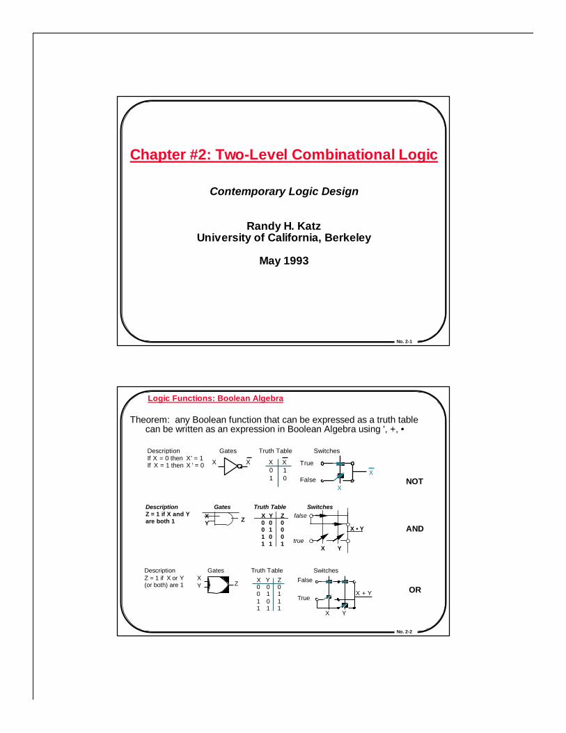
Logic Functions: Boolean Algebra
Theorem: any Boolean function that can be expressed as a truth table can be written as an expression in Boolean Algebra using ', +, •
Description Z = 1 if X and Y are both 1
Gates Truth Table SwitchesXY Z
Y 0 1 0 1
X 0 0 1 1
Z 0 0 0 1
X Y
X • Y
false
true
NOT
AND
OR
Description If X = 0 then X ' = 1 If X = 1 then X ' = 0
Switches Gates
X
X X 0 1
X 1 0
T ruth T able
X T rue
False X
Description Z = 1 if X or Y (or both) are 1
Gates T ruth T able Switches X Y Z X
0 0 1 1
Y 0 1 0 1
Z 0 1 1 1
X Y
X + Y
False
T rue
No. 2-3
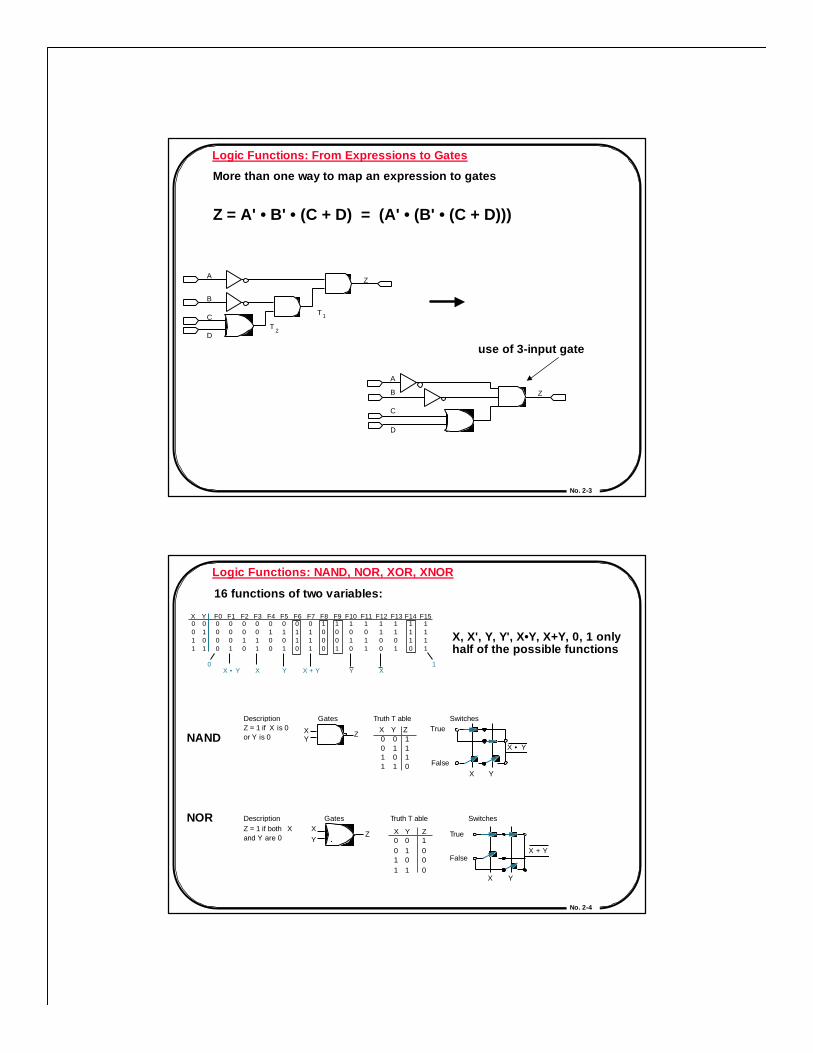
Logic Functions: From Expressions to Gates
More than one way to map an expression to gates
Z = A' • B' • (C + D) = (A' • (B' • (C + D)))
use of 3-input gate
A
B
C
D T
2
T 1
Z
Z
A
B
C
D
No. 2-4
F0 0 0 0 0
F1 0 0 0 1
F2 0 0 1 0
F3 0 0 1 1
F4 0 1 0 0
F5 0 1 0 1
F6 0 1 1 0
F7 0 1 1 1
F8 1 0 0 0
F9 1 0 0 1
F10 1 0 1 0
F1 1 1 0 1 1
F12 1 1 0 0
F13 1 1 0 1
F14 1 1 1 0
F15 1 1 1 1
X 0 0 1 1
Y 0 1 0 1
0 X • Y X Y X + Y X Y
1
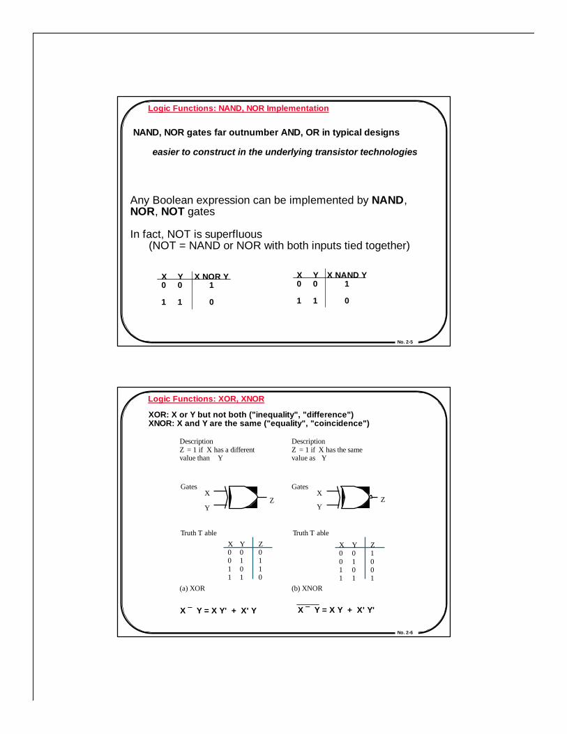
Logic Functions: NAND, NOR, XOR, XNOR
16 functions of two variables:
X, X', Y, Y', X•Y, X+Y, 0, 1 only half of the possible functions
NAND
NOR
Description Z = 1 if X is 0 or Y is 0
Gates T ruth T able Switches
X Y
X • Y
False
T rue X 0 0 1 1
Y 0 1 0 1
Z 1 1 1 0
X Y
Z
Description Z = 1 if both X and Y are 0
Gates T ruth T able Switches X Y
Z X 0 0 1 1
Y 0 1 0 1
Z 1 0 0 0
X Y
X + Y False
T rue
No. 2-5
Logic Functions: NAND, NOR Implementation
NAND, NOR gates far outnumber AND, OR in typical designs
easier to construct in the underlying transistor technologies
Any Boolean expression can be implemented by NAND,NOR, NOT gates
In fact, NOT is superfluous (NOT = NAND or NOR with both inputs tied together)
X0
1
Y0
1
X NOR Y1
0
X0
1
Y0
1
X NAND Y1
0
No. 2-6
Logic Functions: XOR, XNOR
XOR: X or Y but not both ("inequality", "difference")XNOR: X and Y are the same ("equality", "coincidence")
X ⊕ Y = X Y' + X' Y X ⊕ Y = X Y + X' Y'
(a) XOR (b) XNOR
Description Z = 1 if X has a different value than Y
Gates
T ruth T able
X
Y Z
X 0 0 1 1
Y 0 1 0 1
Z 0 1 1 0
Description Z = 1 if X has the same value as Y
Gates
T ruth T able
X
Y Z
X 0 0 1 1
Y 0 1 0 1
Z 1 0 0 1
No. 2-7
Logic Functions: Rationale for Simplification
Logic Minimization: reduce complexity of the gate level implementation
• reduce number of literals (gate inputs)
• reduce number of gates
• reduce number of levels of gates
fewer inputs implies faster gates in some technologies
fan-ins (number of gate inputs) are limited in some technologies
fewer levels of gates implies reduced signal propagation delays
minimum delay configuration typically requires more gates
number of gates (or gate packages) influences manufacturingcosts
No. 2-8
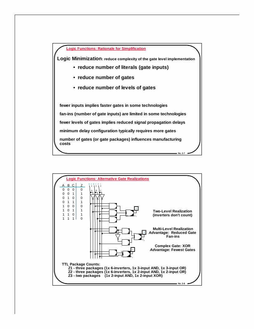
Logic Functions: Alternative Gate Realizations
Two-Level Realization(inverters don't count)
Multi-Level RealizationAdvantage: Reduced Gate
Fan-ins
Complex Gate: XORAdvantage: Fewest Gates
TTL Package Counts: Z1 - three packages (1x 6-inverters, 1x 3-input AND, 1x 3-input OR) Z2 - three packages (1x 6-inverters, 1x 2-input AND, 1x 2-input OR) Z3 - two packages (1x 2-input AND, 1x 2-input XOR)
0 1 0 1 0 1
A B C
0
0
Z 1
Z 2
Z 3
0
A 0 0 0 0 1 1 1 1
B 0 0 1 1 0 0 1 1
C 0 1 0 1 0 1 0 1
Z 0 1 0 1 0 1 1 0

No. 2-9
Gate Logic: Laws of Boolean Algebra
Prove the theorem: X • Y + X • Y' = X
X • Y + X •Y' = X • (Y + Y')
X • (Y + Y') = X • (1)
X • (1) = X
distributive law (8)
complementary law (5)
identity (1D)
Prove the theorem: X + X • Y = X
X + X • Y = X • 1 + X • Y
X • 1 + X • Y = X • (1 + Y)
X • (1 + Y) = X • (1)
X • (1) = X
identity (1D)
distributive law (8)
identity (2)
identity (1)
No. 2-10
Gate Logic: Laws of Boolean Algebra
DeMorgan's Law
(X + Y)' = X' • Y'
(X • Y)' = X' + Y'
NOR is equivalent to ANDwith inputs complemented
NAND is equivalent to ORwith inputs complemented
Example:
Z = A' B' C + A' B C + A B' C + A B C'
Z' = (A + B + C') • (A + B' + C') • (A' + B + C') • (A' + B' + C)
DeMorgan's Law can be used to convert AND/OR expressionsto OR/AND expressions
DeMorgan's Law can be used to convert AND/OR expressionsto OR/AND expressions
X 0 0 1 1
Y 0 1 0 1
X 1 1 0 0
Y 1 0 1 0
X + Y 1 0 0 0
X•Y 1 0 0 0
X 0 0 1 1
Y 0 1 0 1
X 1 1 0 0
Y 1 0 1 0
X + Y 1 1 1 0
X•Y 1 1 1 0

No. 2-11
Gate Logic: Laws of Boolean Algebra
Apply the laws and theorems to simplify Boolean equations
Example: full adder's carry out function
Cout = A' B Cin + A B' Cin + A B Cin' + A B Cin
No. 2-12
Gate Logic: Laws of Boolean Algebra
Apply the laws and theorems to simplify Boolean equations
Example: full adder's carry out function
Cout = A' B Cin + A B' Cin + A B Cin' + A B Cin
= A' B Cin + A B' Cin + A B Cin' + A B Cin + A B Cin
= A' B Cin + A B Cin + A B' Cin + A B Cin' + A B Cin
= (A' + A) B Cin + A B' Cin + A B Cin' + A B Cin
= (1) B Cin + A B' Cin + A B Cin' + A B Cin
= B Cin + A B' Cin + A B Cin' + A B Cin + A B Cin
= B Cin + A B' Cin + A B Cin + A B Cin' + A B Cin
= B Cin + A (B' + B) Cin + A B Cin' + A B Cin
= B Cin + A (1) Cin + A B Cin' + A B Cin
= B Cin + A Cin + A B (Cin' + Cin)
= B Cin + A Cin + A B (1)
= B Cin + A Cin + A B
identity
associative

No. 2-13
Gate Logic: 2-Level Canonical Forms
Many alternative expressions (and gate realizations) mayhave the same truth table
Canonical form: standard form for a Boolean expression provides a unique algebraic signature
Sum of Products Formalso known as disjunctive normal form, minterm expansion
F = A' B C + A B' C' + A B' C + A B C' + A B C0 1 1 1 0 0 1 0 1 1 1 0 1 1 1
F' = A' B' C' + A' B' C + A' B C'
F 0 0 0 1 1 1 1 1
F 1 1 1 0 0 0 0 0
C 0 1 0 1 0 1 0 1
B 0 0 1 1 0 0 1 1
A 0 0 0 0 1 1 1 1
No. 2-14
Sum of Products product term / minterm:ANDed product of literals in which eachvariable appears exactly once, in true orcomplemented form (but not both!)
F(A,B,C) = Σm(3,4,5,6,7)
= m3 + m4 + m5 + m6 + m7
= A' B C + A B' C' + A B' C + A B C' + A B C
F = A B' (C + C') + A' B C + A B (C' + C)
= A B' + A' B C + A B= A (B' + B) + A' B C= A + A' B C= A + B C
B
C
A
F
A B C = m 1 A B C = m 2 A B C = m 3 A B C = m 4 A B C = m 5 A B C = m 6 A B C = m 7
A 0 0 0 0 1 1 1 1
B 0 0 1 1 0 0 1 1
C 0 1 0 1 0 1 0 1
Minterms A B C = m 0

No. 2-15
Product of Sums / Conjunctive Normal Form / Maxterm Expansion
Maxterm Shorthand Notation
Maxterm:ORed sum of literals in which eachvariable appears exactly once in eithertrue or complemented form, but not both!
Maxterm form:Find truth table rows where F is 0 0 implies true literal 1 implies complemented literal
F(A,B,C) = ΠM(0,1,2)= (A + B + C) (A + B + C') (A + B' + C)
F’(A,B,C) = ΠM(3,4,5,6,7)
= (A + B' + C') (A' + B + C) (A' + B + C') (A' + B' + C) (A' + B' + C')
A 0 0 0 0 1 1 1 1
B 0 0 1 1 0 0 1 1
C 0 1 0 1 0 1 0 1
Maxterms A + B + C = M 0 A + B + C = M 1 A + B + C = M 2 A + B + C = M 3 A + B + C = M 4 A + B + C = M 5 A + B + C = M 6 A + B + C = M 7
No. 2-16
Sum of Products, Products of Sums, and DeMorgan's Law
F' = A' B' C' + A' B' C + A' B C'
Apply DeMorgan's Law to obtain F:
(F')' = (A' B' C' + A' B' C + A' B C')'
F = (A + B + C) (A + B + C') (A + B' + C)
F' = (A + B' + C') (A' + B + C) (A' + B + C') (A' + B' + C) (A' + B' + C')
(F')' = {(A + B' + C') (A' + B + C) (A' + B + C') (A' + B' + C) (A' + B' + C')}'
F = A' B C + A B' C' + A B' C + A B C' + A B C
Apply DeMorgan's Law to obtain F:
No. 2-17
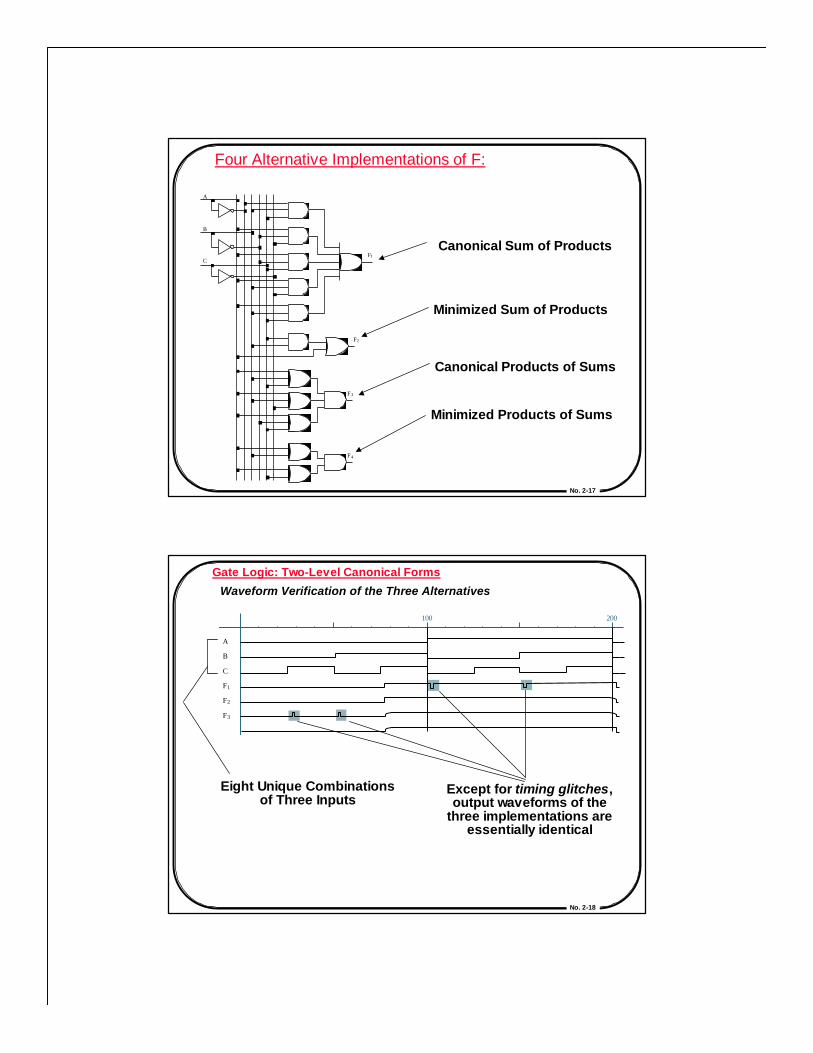
Four Alternative Implementations of F:
Canonical Sum of Products
Minimized Sum of Products
Canonical Products of Sums
Minimized Products of Sums
A
B
F 2
F 3
F 4
F 1 C
No. 2-18
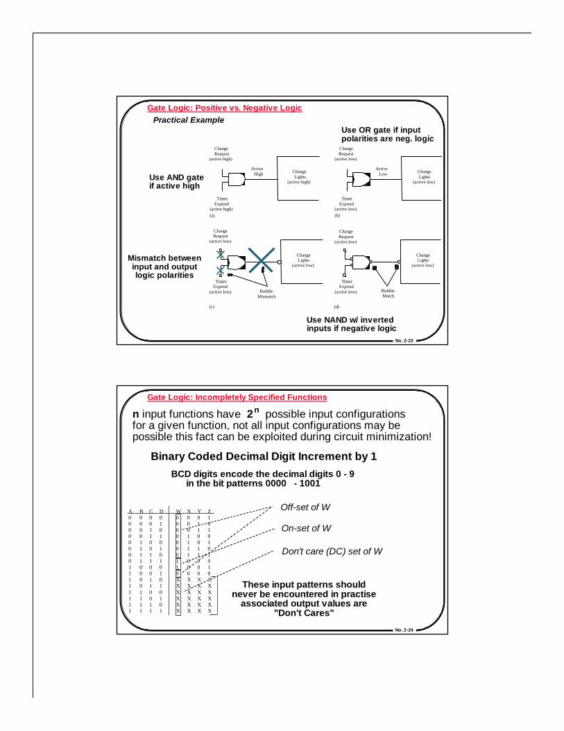
Gate Logic: Two-Level Canonical Forms
Waveform Verification of the Three Alternatives
Eight Unique Combinationsof Three Inputs
Except for timing glitches,output waveforms of the
three implementations areessentially identical
100 200
A
B
C
F 1
F 2
F 3

No. 2-19
Gate Logic: Two-Level Canonical FormsMapping Between Forms
1. Minterm to Maxterm conversion: rewrite minterm shorthand using maxterm shorthand
replace minterm indices with the indices not already used
F(A,B,C) = Σm(3,4,5,6,7) = ΠM(0,1,2)
2. Maxterm to Minterm conversion:rewrite maxterm shorthand using minterm shorthandreplace maxterm indices with the indices not already used
F(A,B,C) = ΠM(0,1,2) = Σm(3,4,5,6,7)
No. 2-20
in minterm shorthand, list indices not already used in F
F(A,B,C) = Σm(3,4,5,6,7) F'(A,B,C) = Σm(0,1,2) = ΠM(0,1,2) = ΠM(3,4,5,6,7)
3. Minterm expansion of F to Minterm expansion of F':
4. Minterm expansion of F to Maxterm expansion of F':
rewrite in Maxterm form, using the same indices as F
F(A,B,C) = Σm(3,4,5,6,7) F'(A,B,C) = ΠM(3,4,5,6,7) = ΠM(0,1,2) = Σm(0,1,2)

No. 2-21
Gate Logic: Positive vs. Negative Logic
Normal Convention: Postive Logic/Active HighLow Voltage = 0; High Voltage = 1
Alternative Convention sometimes used: Negative Logic/Active Low
Behavior in termsof Electrical Levels
Two Alternative InterpretationsPositive Logic ANDNegative Logic OR
Dual Operations
Negative Logic Positive Logic V oltage T ruth T able
F low low low high
F 0 0 0 1
F 1 1 1 0
A low low
high high
B low
high low
high
B 0 1 0 1
A 0 0 1 1
A 1 1 0 0
B 1 0 1 0
F
No. 2-22
Conversion from Positive to Negative Logic
Positive Logic NOR: A + B = A • B
Negative Logic NAND: A • B = A + B
Dual operations: AND becomes OR, OR becomes AND Complements remain unchanged
Negative Logic Positive Logic V oltage T ruth T able
F high low low low
F 1 0 0 0
F 0 1 1 1
A low low high high
B low high low high
B 0 1 0 1
A 0 0 1 1
A 1 1 0 0
B 1 0 1 0
F
No. 2-23
(c)
Change Request
(active low)
T imer Expired
(active low)
Change Lights
(active low)
Bubble Mismatch
(d)
(a)
Change Request
(active high)
T imer Expired
(active high)
Change Lights
(active high)
Active High
(b)
Change Request
(active low)
T imer Expired
(active low)
Change Lights
(active low)
Active Low
Change Request
(active low)
T imer Expired
(active low)
Change Lights
(active low)
Bubble Match
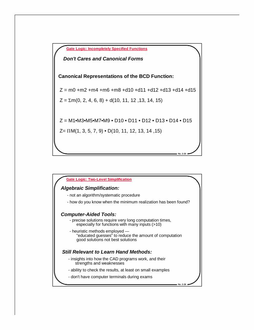
Gate Logic: Positive vs. Negative LogicPractical Example
Mismatch betweeninput and outputlogic polarities
Use NAND w/ invertedinputs if negative logic
Use OR gate if inputpolarities are neg. logic
Use AND gateif active high
No. 2-24
A 0 0 0 0 0 0 0 0 1 1 1 1 1 1 1 1
B 0 0 0 0 1 1 1 1 0 0 0 0 1 1 1 1
C 0 0 1 1 0 0 1 1 0 0 1 1 0 0 1 1
D 0 1 0 1 0 1 0 1 0 1 0 1 0 1 0 1
W 0 0 0 0 0 0 0 1 1 0 X X X X X X
X 0 0 0 1 1 1 1 0 0 0 X X X X X X
Y 0 1 1 0 0 1 1 0 0 0 X X X X X X
Z 1 0 1 0 1 0 1 0 1 0 X X X X X X
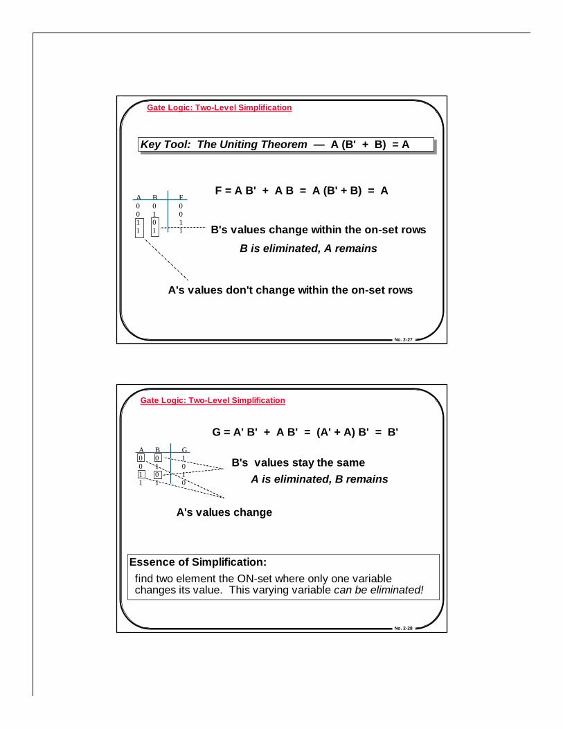
Gate Logic: Incompletely Specified Functions
n input functions have 2 possible input configurationsfor a given function, not all input configurations may bepossible this fact can be exploited during circuit minimization!
Binary Coded Decimal Digit Increment by 1BCD digits encode the decimal digits 0 - 9 in the bit patterns 0000 - 1001
n
These input patterns shouldnever be encountered in practise
associated output values are"Don't Cares"
Off-set of W
On-set of W
Don't care (DC) set of W
No. 2-25
Gate Logic: Incompletely Specified Functions
Don't Cares and Canonical Forms
Z = m0 +m2 +m4 +m6 +m8 +d10 +d11 +d12 +d13 +d14 +d15
Z = Σm(0, 2, 4, 6, 8) + d(10, 11, 12 ,13, 14, 15)
Z = M1•M3•M5•M7•M9 • D10 • D11 • D12 • D13 • D14 • D15
Z= ΠM(1, 3, 5, 7, 9) • D(10, 11, 12, 13, 14 ,15)
Canonical Representations of the BCD Function:
No. 2-26
Gate Logic: Two-Level Simplification
Algebraic Simplification:- not an algorithm/systematic procedure
- how do you know when the minimum realization has been found?
Computer-Aided Tools:- precise solutions require very long computation times, especially for functions with many inputs (>10)
- heuristic methods employed — "educated guesses" to reduce the amount of computation good solutions not best solutions
Still Relevant to Learn Hand Methods:- insights into how the CAD programs work, and their strengths and weaknesses
- ability to check the results, at least on small examples
- don't have computer terminals during exams
No. 2-27
A 0 0 1 1
B 0 1 0 1
F 0 0 1 1
Gate Logic: Two-Level Simplification
Key Tool: The Uniting Theorem — A (B' + B) = AKey Tool: The Uniting Theorem — A (B' + B) = A
F = A B' + A B = A (B' + B) = A
A's values don't change within the on-set rows
B's values change within the on-set rows
B is eliminated, A remains
No. 2-28
Gate Logic: Two-Level Simplification
A 0 0 1 1
B 0 1 0 1
G 1 0 1 0
G = A' B' + A B' = (A' + A) B' = B'
B's values stay the same
A's values change
A is eliminated, B remains
Essence of Simplification:find two element the ON-set where only one variablechanges its value. This varying variable can be eliminated!

No. 2-29
A B 0 1
0
1
0
1
2
3
0
1
2
3
6
7
4
5
AB C
0
1
3
2
4
5
7
6
12
13
15
14
8
9
11
10
A
B
AB CD
A
00 01 11 10
0
1
00 01 11 00
00
01
11
10 C
B
D
Karnaugh Map Method
K-map is an alternative method of representing the truth tablethat helps visualize adjacencies in up to 6 dimensions
Beyond that, computer-based methods are needed
2-variableK-map
3-variableK-map
4-variableK-map
Numbering Scheme: 00, 01, 11, 10Gray Code — only a single bit changes from code word to next code word
No. 2-30
Karnaugh Map Method: Adjacencies in the K-Map
Wrap from first to last column
Top row to bottom row
000
001
010
01 1
1 10
1 1 1
100
101
00 01 11 10
0
1
AB C
A
B
011
010
000
001
100
110
101
111
B
C
A

No. 2-31
Gate Logic: Two-Level Simplification
F =
A asserted, unchangedB varies
G =
B complemented, unchangedA varies
Cout = F(A,B,C) =
A B 0 1
0 1
0 1
0
1
A B 0 1
1 1
0 0
0
1
A B A
B
Cin 00 01 11 10
0
1
0
0
0
1
1
1
0
1
AB C
A
00 01 11 10
0
1
0
0
0
0
1
1
1
1
B
No. 2-32
Gate Logic: Two-Level Simplification
F = A
A asserted, unchangedB varies
G = B'
B complemented, unchangedA varies
Cout = A B + B Cin + A Cin F(A,B,C) = A
A B 0 1
0 1
0 1
0
1
A B 0 1
1 1
0 0
0
1
A B A
B
Cin 00 01 11 10
0
1
0
0
0
1
1
1
0
1
AB C
A
00 01 11 10
0
1
0
0
0
0
1
1
1
1
B
No. 2-33
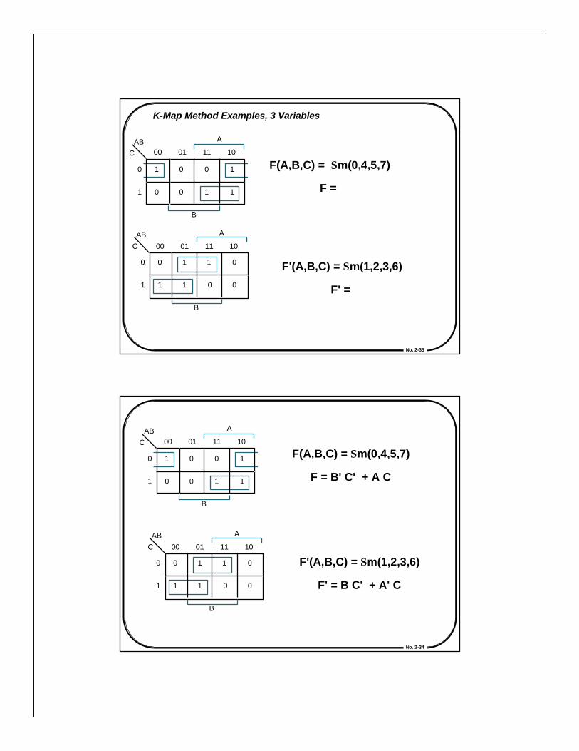
K-Map Method Examples, 3 Variables
F(A,B,C) = Σm(0,4,5,7)
F =
F'(A,B,C) = Σm(1,2,3,6)
F' =
00 C AB
01 11 10
1 0 0 1
1 1 0 0
A
B
0
1
00 C AB
01 11 10
0 1 1 0
0 0 1 1
A
B
0
1
No. 2-34
F(A,B,C) = Σm(0,4,5,7)
F = B' C' + A C
F'(A,B,C) = Σm(1,2,3,6)
F' = B C' + A' C
00 C AB
01 11 10
1 0 0 1
1 1 0 0
A
B
0
1
00 C AB
01 11 10
0 1 1 0
0 0 1 1
A
B
0
1
No. 2-35
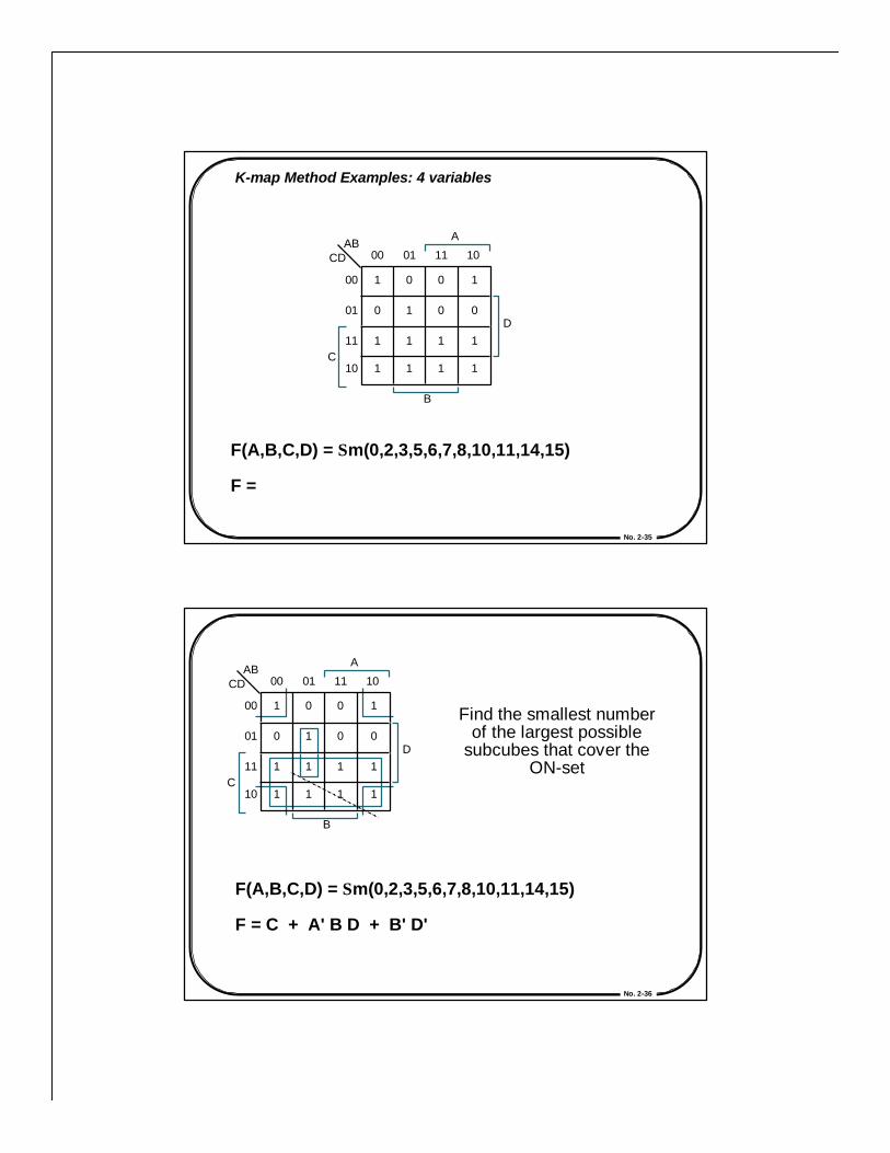
K-map Method Examples: 4 variables
F(A,B,C,D) = Σm(0,2,3,5,6,7,8,10,11,14,15)
F =
AB 00 01 11 10
1 0 0 1
0 1 0 0
1 1 1 1
1 1 1 1
00
01
11
10 C
CD
A
D
B
No. 2-36
F(A,B,C,D) = Σm(0,2,3,5,6,7,8,10,11,14,15)
F = C + A' B D + B' D'
Find the smallest numberof the largest possible
subcubes that cover theON-set
AB 00 01 11 10
1 0 0 1
0 1 0 0
1 1 1 1
1 1 1 1
00
01
11
10 C
CD
A
D
B
No. 2-37
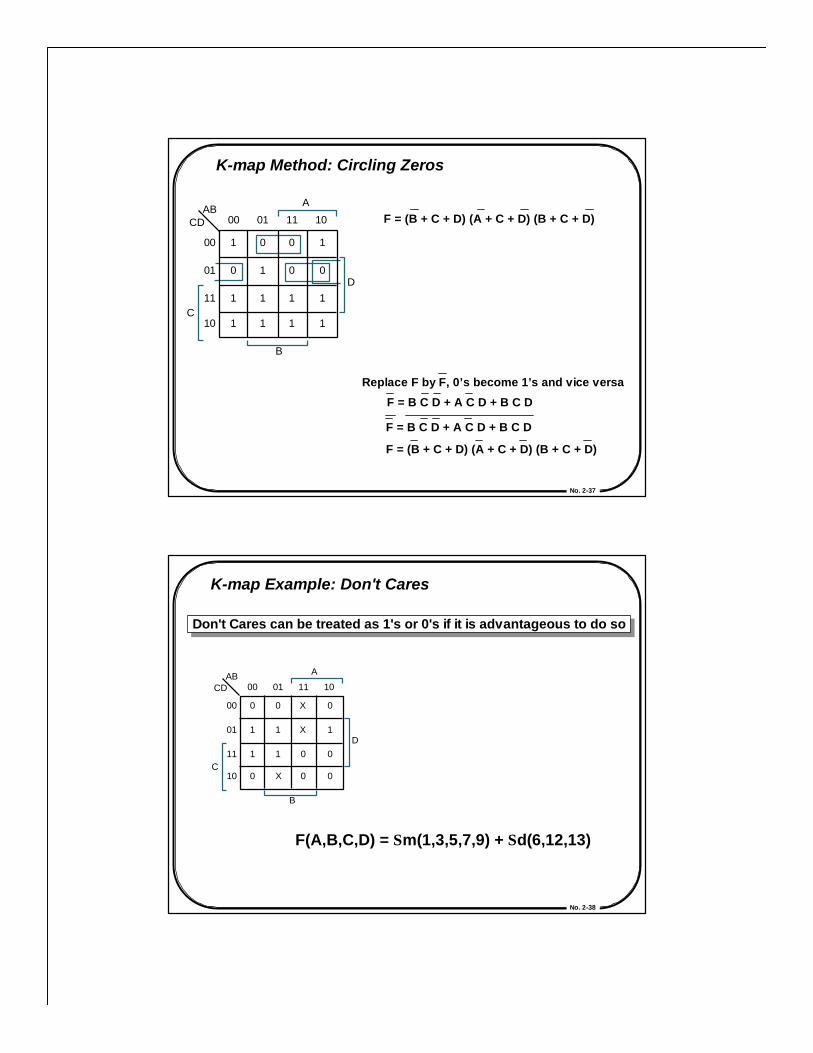
K-map Method: Circling Zeros
AB 00 01 11 10
1 0 0 1
0 1 0 0
1 1 1 1
1 1 1 1
00
01
11
10 C
CD
A
D
B
F = (B + C + D) (A + C + D) (B + C + D)
F = B C D + A C D + B C D
F = B C D + A C D + B C D
F = (B + C + D) (A + C + D) (B + C + D)
Replace F by F, 0’s become 1’s and vice versa
No. 2-38
K-map Example: Don't Cares
F(A,B,C,D) = Σm(1,3,5,7,9) + Σd(6,12,13)
Don't Cares can be treated as 1's or 0's if it is advantageous to do soDon't Cares can be treated as 1's or 0's if it is advantageous to do so
AB 00 01 11 10
0 0 X 0
1 1 X 1
1 1 0 0
0 X 0 0
00
01
11
10 C
CD
A
D
B

No. 2-39
Gate Logic: Two-Level Simplification
F(A,B,C,D) = Σm(1,3,5,7,9) + Σd(6,12,13)
F = A'D + B' C' D
F = C' D + A' D w/ DCs
AB 00 01 11 10
0 0 X 0
1 1 X 1
1 1 0 0
0 X 0 0
00
01
11
10 C
CD
A
D
B AB
00 01 11 10
0 0 X 0
1 1 X 1
1 1 0 0
0 X 0 0
00
01
11
10 C
CD
A
D
B
In PoS form: F = D (A' + C')
Same answer as above,but fewer literals
No. 2-40
Gate Logic: Two-Level SimplificationDesign Example: Two Bit Comparator
A 4-Variable K-map for each of the 3output functions
F 1 1 0 0 0 0 1 0 0 0 0 1 0 0 0 0 1
F 2 0 1 1 1 0 0 1 1 0 0 0 1 0 0 0 0
F 3 0 0 0 0 1 0 0 0 1 1 0 0 1 1 1 0
D 0 1 0 1 0 1 0 1 0 1 0 1 0 1 0 1
C 0 0 1 1 0 0 1 1 0 0 1 1 0 0 1 1
B 0 1 0 1
A 0 0 1 1
=, >, < F 1 A B = C D F 2 A B < C D F 3 A B > C D
A B
C D
N 1
N 2
No. 2-41
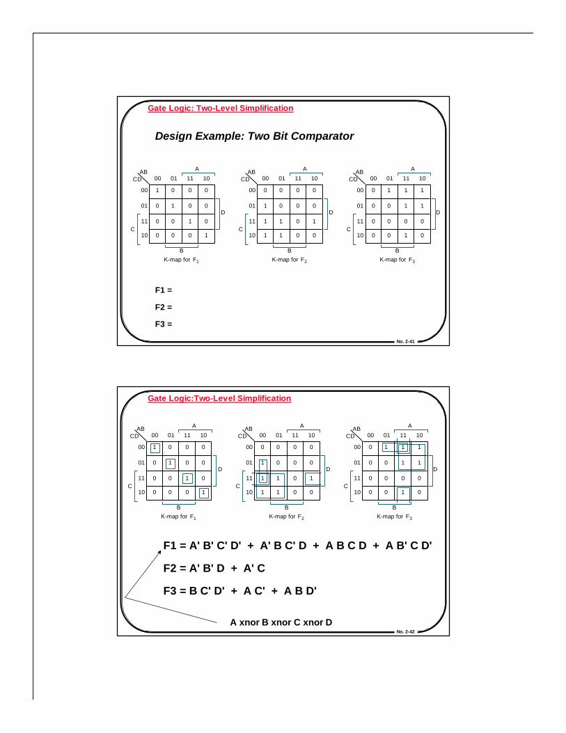
Gate Logic: Two-Level Simplification
Design Example: Two Bit Comparator
F1 =
F2 =
F3 =
AB 00 01 11 10
1 0 0 0
0 1 0 0
0 0 1 0
0 0 0 1
00
01
11
10 C
CD
A
D
B K-map for F 1
AB 00 01 11 10
0 0 0 0
1 0 0 0
1 1 0 1
1 1 0 0
00
01
11
10 C
CD
A
D
B K-map for F 2
AB 00 01 11 10
0 1 1 1
0 0 1 1
0 0 0 0
0 0 1 0
00
01
11
10 C
CD
A
D
B K-map for F 3
No. 2-42
Gate Logic:Two-Level Simplification
F1 = A' B' C' D' + A' B C' D + A B C D + A B' C D'
F2 = A' B' D + A' C
F3 = B C' D' + A C' + A B D'
A xnor B xnor C xnor D
AB 00 01 11 10
1 0 0 0
0 1 0 0
0 0 1 0
0 0 0 1
00
01
11
10 C
CD
A
D
B K-map for F 1
AB 00 01 11 10
0 0 0 0
1 0 0 0
1 1 0 1
1 1 0 0
00
01
11
10 C
CD
A
D
B K-map for F 2
AB 00 01 11 10
0 1 1 1
0 0 1 1
0 0 0 0
0 0 1 0
00
01
11
10 C
CD
A
D
B K-map for F 3
No. 2-43
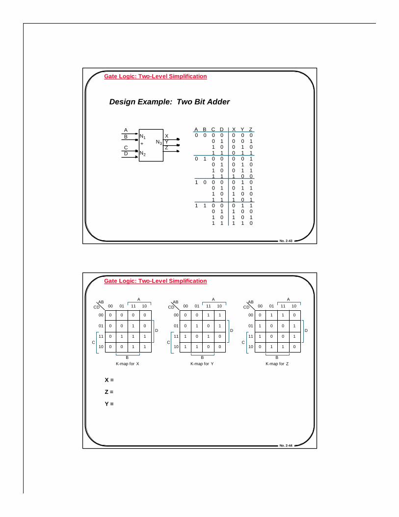
Gate Logic: Two-Level Simplification
Design Example: Two Bit Adder
+ N 3
X 0 0 0 0 0 0 0 1 0 0 1 1 0 1 1 1
Y 0 0 1 1 0 1 1 0 1 1 0 0 1 0 0 1
Z 0 1 0 1 1 0 1 0 0 1 0 1 1 0 1 0
D 0 1 0 1 0 1 0 1 0 1 0 1 0 1 0 1
C 0 0 1 1 0 0 1 1 0 0 1 1 0 0 1 1
B 0 1 0 1
A 0 0 1 1
A B
C D
N 1
N 2
X Y Z
No. 2-44
Gate Logic: Two-Level Simplification
X =
Z =
Y =
AB 00 01 11 10
0 0 0 0
0 0 1 0
0 1 1 1
0 0 1 1
00
01
11
10 C
CD
A
D
B K-map for X
AB 00 01 11 10
0 0 1 1
0 1 0 1
1 0 1 0
1 1 0 0
00
01
11
10 C
CD
A
D
B K-map for Y
AB 00 01 11 10
0 1 1 0
1 0 0 1
1 0 0 1
0 1 1 0
00
01
11
10 C
CD
A
D
B K-map for Z
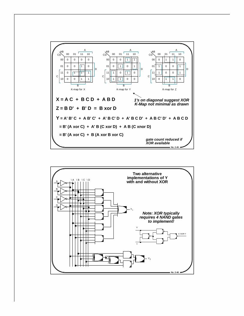
No. 2-45
X = A C + B C D + A B D
Z = B D' + B' D = B xor D
Y = A' B' C + A B' C' + A' B C' D + A' B C D' + A B C' D' + A B C D
= B' (A xor C) + A' B (C xor D) + A B (C xnor D)
= B' (A xor C) + B (A xor B xor C)gate count reduced ifXOR available
1's on diagonal suggest XORK-Map not minimal as drawn
AB 00 01 11 10
0 0 0 0
0 0 1 0
0 1 1 1
0 0 1 1
00
01
11
10 C
CD
A
D
B K-map for X
AB 00 01 11 10
0 0 1 1
0 1 0 1
1 0 1 0
1 1 0 0
00
01
11
10 C
CD
A
D
B K-map for Y
AB 00 01 11 10
0 1 1 0
1 0 0 1
1 0 0 1
0 1 1 0
00
01
11
10 C
CD
A
D
B K-map for Z
No. 2-46
\ D \ A \ C
Y 1
A
C
D
\ B
B
Y 2
Two alternativeimplementations of Ywith and without XOR
Note: XOR typicallyrequires 4 NAND gates
to implement!
X XOR Y
X
Y
No. 2-47
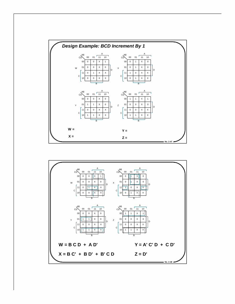
Design Example: BCD Increment By 1
W =
X =
Y =
Z =
AB 00 01 11 10
0 0 X 1
0 0 X 0
0 1 X X
0 0 X X
00
01
11
10 C
CD
A
D
B
AB 00 01 11 10
0 1 X 0
0 1 X 0
1 0 X X
0 1 X X
00
01
11
10 C
CD
A
D
B
AB 00 01 11 10
0 0 X 0
1 1 X 0
0 0 X X
1 1 X X
00
01
11
10 C
CD
A
D
B
AB 00 01 11 10
1 1 X 1
0 0 X 0
0 0 X X
1 1 X X
00
01
11
10 C
CD
A
D
B
Z Y
X W
No. 2-48
W = B C D + A D'
X = B C' + B D' + B' C D
Y = A' C' D + C D'
Z = D'
AB 00 01 11 10
0 0 X 1
0 0 X 0
0 1 X X
0 0 X X
00
01
11
10 C
CD
A
D
B
AB 00 01 11 10
0 1 X 0
0 1 X 0
1 0 X X
0 1 X X
00
01
11
10 C
CD
A
D
B
AB 00 01 11 10
0 0 X 0
1 1 X 0
0 0 X X
1 1 X X
00
01
11
10 C
CD
A
D
B
AB 00 01 11 10
1 1 X 1
0 0 X 0
0 0 X X
1 1 X X
00
01
11
10 C
CD
A
D
B
Z Y
X W
No. 2-49
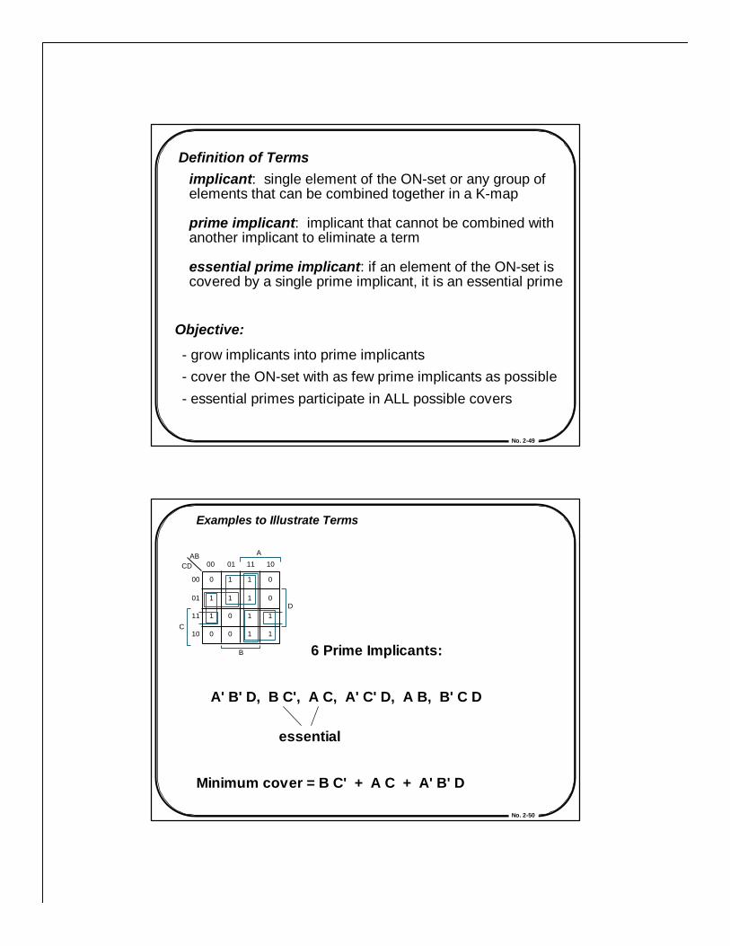
Definition of Termsimplicant: single element of the ON-set or any group ofelements that can be combined together in a K-map
prime implicant: implicant that cannot be combined withanother implicant to eliminate a term
essential prime implicant: if an element of the ON-set iscovered by a single prime implicant, it is an essential prime
Objective:
- grow implicants into prime implicants- cover the ON-set with as few prime implicants as possible- essential primes participate in ALL possible covers
No. 2-50
Examples to Illustrate Terms
6 Prime Implicants:
A' B' D, B C', A C, A' C' D, A B, B' C D
essential
Minimum cover = B C' + A C + A' B' D
AB 00 01 11 10
0 1 1 0
1 1 1 0
1 0 1 1
0 0 1 1
00
01
11
10 C
CD
A
D
B
No. 2-51
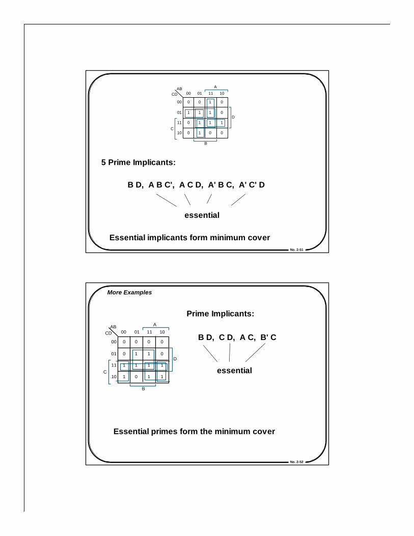
5 Prime Implicants:
B D, A B C', A C D, A' B C, A' C' D
essential
Essential implicants form minimum cover
AB 00 01 11 10
0 0 1 0
1 1 1 0
0 1 1 1
0 1 0 0
00
01
11
10 C
CD
A
D
B
No. 2-52
More Examples
Prime Implicants:
B D, C D, A C, B' C
essential
Essential primes form the minimum cover
AB 00 01 11 10
0 0 0 0
0 1 1 0
1 1 1 1
1 0 1 1
00
01
11
10 C
CD
A
D
B
No. 2-53
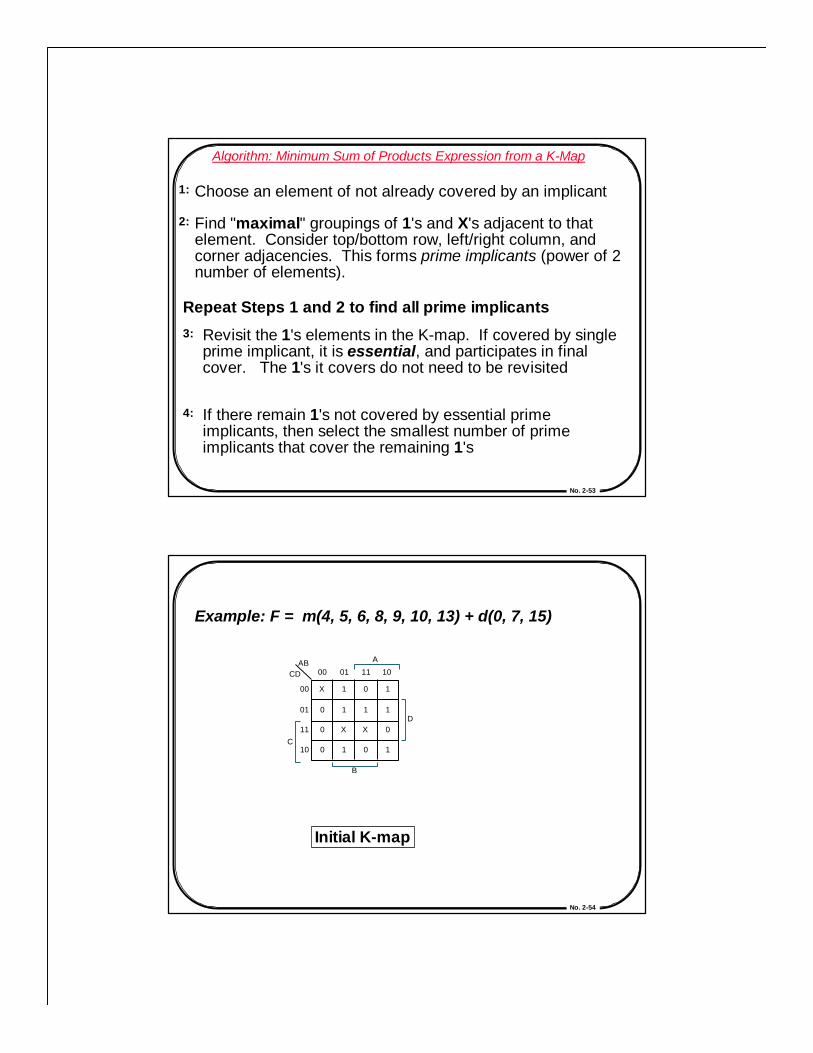
Algorithm: Minimum Sum of Products Expression from a K-Map
1: Choose an element of not already covered by an implicant
2: Find "maximal" groupings of 1's and X's adjacent to thatelement. Consider top/bottom row, left/right column, andcorner adjacencies. This forms prime implicants (power of 2number of elements).
Repeat Steps 1 and 2 to find all prime implicants3: Revisit the 1's elements in the K-map. If covered by single
prime implicant, it is essential, and participates in finalcover. The 1's it covers do not need to be revisited
4: If there remain 1's not covered by essential primeimplicants, then select the smallest number of primeimplicants that cover the remaining 1's
No. 2-54
Example: F = m(4, 5, 6, 8, 9, 10, 13) + d(0, 7, 15)
Initial K-map
AB 00 01 11 10
X 1 0 1
0 1 1 1
0 X X 0
0 1 0 1
00
01
11
10 C
CD
A
D
B

No. 2-55
Initial K-map Primes aroundA' B C' D'
Primes aroundA B C' D
AB 00 01 11 10
X 1 0 1
0 1 1 1
0 X X 0
0 1 0 1
00
01
11
10 C
CD
A
D
B
AB 00 01 11 10
X 1 0 1
0 1 1 1
0 X X 0
0 1 0 1
00
01
11
10 C
CD
A
D
B
AB 00 01 11 10
X 1 0 1
0 1 1 1
0 X X 0
0 1 0 1
00
01
11
10 C
CD
A
D
B
No. 2-56
Gate Logic: Two-Level SimplificationExample Continued
Primes aroundA B' C' D'
Primes aroundA B C' D
AB 00 01 11 10
X 1 0 1
0 1 1 1
0 X X 0
0 1 0 1
00
01
11
10 C
CD
A
D
B
AB 00 01 11 10
X 1 0 1
0 1 1 1
0 X X 0
0 1 0 1
00
01
11
10 C
CD
A
D
B
AB 00 01 11 10
X 1 0 1
0 1 1 1
0 X X 0
0 1 0 1
00
01
11
10 C
CD
A
D
B
Essential Primeswith Min Cover

No. 2-57
5-Variable K-maps
F = Σm(2, 5, 7, 8, 10, 13, 15, 17, 19, 21, 23, 24, 29, 31)
1
00
1
10
1
10 BC
DE 00 01 11 00
01
11
10
A=0
BC DE 00 01 11
01
11
10
A=1
1 1
1
1 1
1
1 1
1 1 1
No. 2-58
F = C E + A B' E + B C' D' E' + A' C' D E'
BC DE 00 01 11 10
00
01
11
10
A=0
BC DE 00 01 11 10
00
01
11
10
A=1
1 1
1
1
1 1
1
1
1 1 1
1 1 1
No. 2-59
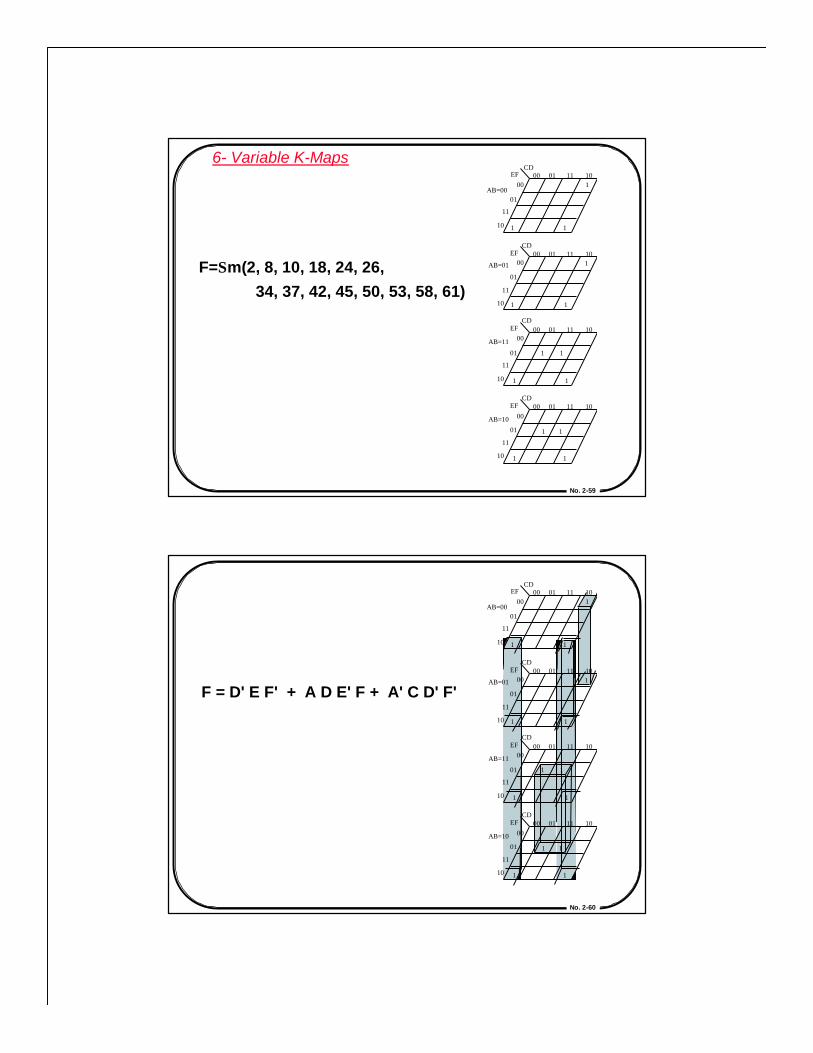
6- Variable K-Maps
F=Σm(2, 8, 10, 18, 24, 26, 34, 37, 42, 45, 50, 53, 58, 61)
CD EF
CD EF
AB =00
AB =01
00 01 11 10 00
01
11
10
00 01 11 10 00
01
11
10
CD EF
AB =11
00 01 11 10 00
01
11
10
CD EF
AB =10
00 01 11 10 00
01
11
10
1
1 1
1
1 1
1 1
1 1
1 1
1 1
No. 2-60
F = D' E F' + A D E' F + A' C D' F'
CD EF
CD EF
AB =00
AB =01
00 01 11 10 00
01
11
10
00 01 11 10 00
01
11
10
CD EF
AB =11
00 01 11 10 00
01
11
10
CD EF
AB =10
00 01 11 10 00
01
11
10
1
1 1
1
1 1
1 1
1 1
1 1
1 1

No. 2-61
Quine-McCluskey Method
Tabular method to systematically find all prime implicants
Implication Table
Column I 0000 0100 1000 0101 0110 1001 1010 0111 1101
1111
F = Σm(4, 5 ,6, 8, 9, 10, 13)
+ Σd(0, 7, 15)
Step 1: Fill Column 1 withminterm and DCs indices.Group by number of 1's.
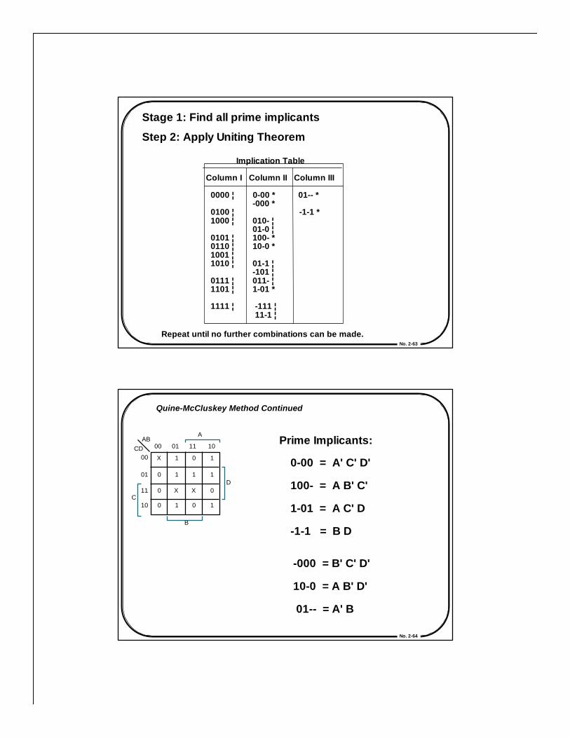
Stage 1: Find all prime implicants
No. 2-62
Implication Table
Column I Column II 0000 ¦ 0-00 -000 0100 ¦ 1000 ¦ 010- 01-0 0101 ¦ 100- 0110 ¦ 10-0 1001 ¦ 1010 ¦ 01-1 -101 0111 ¦ 011- 1101 ¦ 1-01
1111 ¦ -111 11-1
Step 2: Apply Uniting Theorem—Compare elements of group w/ N1's against those with N+1 1's.Differ by one bit implies adjacent.Eliminate variable and place innext column.
E.g., 0000 vs. 0100 yields 0-00 0000 vs. 1000 yields -000
When used in a combination,mark with a check. If cannot becombined, mark with a star.These are the prime implicants.
Repeat until no further combinations can be made.
Stage 1: Find all prime implicants
No. 2-63
Implication Table
Column I Column II Column III
0000 ¦ 0-00 * 01-- * -000 * 0100 ¦ -1-1 * 1000 ¦ 010- ¦ 01-0 ¦ 0101 ¦ 100- * 0110 ¦ 10-0 * 1001 ¦ 1010 ¦ 01-1 ¦ -101 ¦ 0111 ¦ 011- ¦ 1101 ¦ 1-01 *
1111 ¦ -111 ¦ 11-1 ¦
Step 2: Apply Uniting Theorem
Repeat until no further combinations can be made.
Stage 1: Find all prime implicants
No. 2-64
Quine-McCluskey Method Continued
Prime Implicants:
0-00 = A' C' D'
100- = A B' C'
1-01 = A C' D
-1-1 = B D
-000 = B' C' D'
10-0 = A B' D'
01-- = A' B
AB CD 00 01 11 10
00
01
11
10
D
B
C
A
X 1 0 1
0 1 1 1
0 X X 0
0 1 0 1
No. 2-65
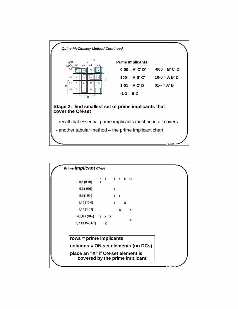
Quine-McCluskey Method Continued
Prime Implicants:
0-00 = A' C' D'
100- = A B' C'
1-01 = A C' D
-1-1 = B D
-000 = B' C' D'
10-0 = A B' D'
01-- = A' B
Stage 2: find smallest set of prime implicants thatcover the ON-set
- recall that essential prime implicants must be in all covers
- another tabular method – the prime implicant chart
AB CD 00 01 11 10
00
01
11
10
D
B
C
A
X 1 0 1
0 1 1 1
0 X X 0
0 1 0 1
No. 2-66
rows = prime implicants
columns = ON-set elements (no DCs)
place an "X" if ON-set element is covered by the prime implicant
Prime Implicant Chart

No. 2-67
If column has a single X, than theimplicant associated with the rowis essential. It must appear inminimum cover
No. 2-68
Eliminate all columns covered byessential primes
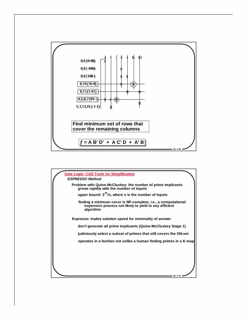
No. 2-69
Find minimum set of rows thatcover the remaining columns
ƒ = A B' D' + A C' D + A' Bƒ = A B' D' + A C' D + A' B
No. 2-70
Gate Logic: CAD Tools for SimplificationESPRESSO Method
Problem with Quine-McCluskey: the number of prime implicants grows rapidly with the number of inputs
upper bound: 3 /n, where n is the number of inputsn
finding a minimum cover is NP-complete, i.e., a computational expensive process not likely to yield to any efficient algorithm
Espresso: trades solution speed for minimality of answer
don't generate all prime implicants (Quine-McCluskey Stage 1)
judiciously select a subset of primes that still covers the ON-set
operates in a fashion not unlike a human finding primes in a K-map

No. 2-71
Gate Logic: CAD Tools for Simplification
Espresso Method: Overview
1. Expands implicants to their maximum sizeImplicants covered by an expanded implicant are removed from further considerationQuality of result depends on order of implicant expansionHeuristic methods used to determine orderStep is called EXPAND
Irredundant cover (i.e., no proper subset is also a cover) is extracted from the expanded primesJust like the Quine-McCluskey Prime Implicant ChartStep is called IRREDUNDANT COVER
Solution usually pretty good, but sometimes can be improvedMight exist another cover with fewer terms or fewer literalsShrink prime implicants to smallest size that still covers ON-setStep is called REDUCE
Repeat sequence REDUCE/EXPAND/IRREDUNDANT COVER to find alternative prime implicantsKeep doing this as long as new covers improve on last solution
A number of optimizations are tried, e.g., identify and remove essential primes early in the process
2.
3.
4.
5.
No. 2-72
Gate Logic: CAD Tools for SimplificationEspresso Iteration (Continued)
Second EXPAND generates adifferent set of prime implicants
IRREDUNDANT COVER found byfinal step of espresso
Only three prime implicants!
AB
CD 00 01 11 10
00
01
11
10
D
B
C
A
1 1 0 0
1 1 1 1
0 0 1 1
1 1 1 1
AB
CD 00 01 11 10
00
01
11
10
D
B
C
A
1 1 0 0
1 1 1 1
0 0 1 1
1 1 1 1