chapter 2 instructions: language of the computer · pdf filechapter 2 instructions: language...
TRANSCRIPT

CMPS290 Class Notes (Chap02) Page 1 / 45 by Kuo-pao Yang
CHAPTER 2
Instructions: Language of the Computer
2.1 Introduction 62
2.2 Operations of the Computer Hardware 63
2.3 Operands of the Computer Hardware 66
2.4 Signed and Unsigned Numbers 73
2.5 Representing Instructions in the Computer 80
2.6 Logical Operations 87
2.7 Instructions for Making Decisions 90
2.8 Supporting Procedures in Computer Hardware 96
2.9 Communicating with People 106
2.10 MIPS Addressing for 32-Bit Immediates and Addresses 111
2.11 Parallelism and Instructions: Synchronization 121
2.12 Translating and Starting a Program 123
2.13 A C Sort Example to Put It All Together 132
2.14 Arrays versus Pointers 141
2.15 Advanced Material: Compiling C and Interpreting Java 145
2.16 Real Stuff: ARM v7 (32-bit) Instructions 145
2.17 Real Stuff: x86 Instructions 149
2.18 Real Stuff: ARM v8 (64-bit) Instructions 158
2.19 Fallacies and Pitfalls 159
2.20 Concluding Remarks 161
2.21 Historical Perspective and Further Reading 163
2.22 Exercises 164

CMPS290 Class Notes (Chap02) Page 2 / 45 by Kuo-pao Yang
2.1 Introduction 62
Instruction Set
o To command a computer’s hardware, you must speak its language. The words of
a computer’s language are called instructions, and its vocabulary is called
instruction set.
o Different computers have different instruction sets
2.2 Operations of the Computer Hardware 63
FIGURE 2.1 MIPS assembly language revealed in this chapter.
CMPS290 Class Notes (Chap02) Page 3 / 45 by Kuo-pao Yang
2.3 Operands of the Computer Hardware 66
Unlike programs in high-level languages, the operands of arithmetic instructions are
restricted; they must be from a limited number of special locations built directly in
hardware called registers. Arithmetic instructions use register operands.
o Word: The natural unit of access in a computer, usually a group of 32 bits;
corresponds to the size of a register in the MIPS architecture. 32-bit data called a
“word”
One major difference between the variables of a programming languages and
registers is the limited number of register, typically 32 on current computers, like
MIPS.
MIPS has a 32 × 32-bit register file
o The size of a register in the MIPS architecture is 32 bits.
o Numbered 0 to 31: $0, $1, … $31
o Assembler names
$t0, $t1, …, $t9 for temporary values
$s0, $s1, …, $s7 for saved variables
Example: Compiling a C Assignment using Registers
o C code:
f = (g + h) - (i + j);
The variables f, g, h, i, and j are assigned to the register in $s0, $s1, $s2, $s3,
and $s4, respectively. What is the compiled MIPS code?
o Compiled MIPS code:
add $t0, $s1, $s2 #$t0 contains g + h
add $t1, $s3, $s4 #$t1 contains i + j
sub $s0, $t0, $t1 # f get $t0 - $t1, which is (g + h) – (i + j)
Memory Operands
Data transfer instruction: A command that moves data between memory and
registers
Address: A value used to delineate the location of a specific data element within a
memory array.
To access a word in memory, the instruction must supply the memory address.
Memory is just a large, single-dimensional array, with the address acting as the index
to that array, starting at 0.
Memory is byte addressed: each address identifies an 8-bit byte.
The data transfer instruction that copies data from memory to a register is
traditionally called load. The actual MIPS name for this instruction is lw, standing for
load word.
CMPS290 Class Notes (Chap02) Page 4 / 45 by Kuo-pao Yang
The instruction complementary to load is traditionally called store; it copies data
from a register to memory. The actual MIPS name is sw, standing for store word.
Alignment restriction: A requirement that data be aligned in memory on natural
boundaries.
In MIPS, words must start at address that are multiples of 4. This requirement is
called an alignment restriction.
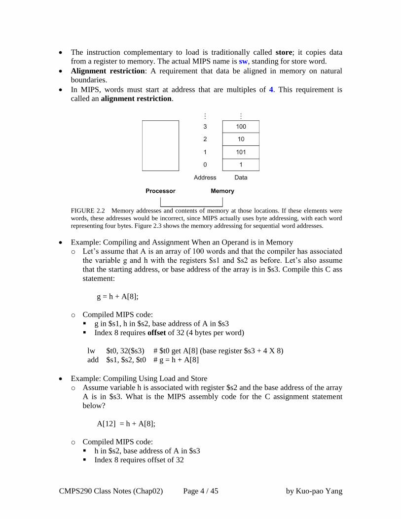
FIGURE 2.2 Memory addresses and contents of memory at those locations. If these elements were
words, these addresses would be incorrect, since MIPS actually uses byte addressing, with each word
representing four bytes. Figure 2.3 shows the memory addressing for sequential word addresses.
Example: Compiling and Assignment When an Operand is in Memory
o Let’s assume that A is an array of 100 words and that the compiler has associated
the variable g and h with the registers $s1 and $s2 as before. Let’s also assume
that the starting address, or base address of the array is in $s3. Compile this C ass
statement:
g = h + A[8];
o Compiled MIPS code:
g in $s1, h in $s2, base address of A in $s3
Index 8 requires offset of 32 (4 bytes per word)
lw $t0, 32($s3) # $t0 get A[8] (base register $s3 + 4 X 8)
add $s1, $s2, $t0 # g = h + A[8]
Example: Compiling Using Load and Store
o Assume variable h is associated with register $s2 and the base address of the array
A is in $s3. What is the MIPS assembly code for the C assignment statement
below?
A[12] = h + A[8];
o Compiled MIPS code:
h in $s2, base address of A in $s3
Index 8 requires offset of 32
CMPS290 Class Notes (Chap02) Page 5 / 45 by Kuo-pao Yang
lw $t0, 32($s3) # $t0 gets A[8]
add $t0, $s2, $t0 # $t0 gets h + A[8]
sw $t0, 48($s3) # $ Store h + A[8] back into A[12]
Registers vs. Memory
o Registers are faster to access than memory
o Operating on memory data requires loads and stores
o Compiler must use registers for variables as much as possible
Constant or Immediate Operands
This quick add instruction with one constant operand is called add immediate or addi.
To add 4 to register $s3, we just write:
addi $s3, $s3, 4 # $s3 = s3 + 4
MIPS register 0 ($zero) is the constant 0. It cannot be overwritten
add $t2, $s1, $zero # $t2 gets $s1
CMPS290 Class Notes (Chap02) Page 6 / 45 by Kuo-pao Yang
2.4 Signed and Unsigned Numbers 73
Unsigned Binary Integers
o Given an n-bit number
0
0
1
1
2n
2n
1n
1n 2x2x2x2xx
o Range: 0 to +2n – 1
o Example
0000 0000 0000 0000 0000 0000 0000 10112
= 0 + … + 1×23 + 0×22 +1×21 +1×20
= 0 + … + 8 + 0 + 2 + 1
= 1110
o Using 32 bits: 0 to +4,294,967,295 (0 to +232 – 1)
Two’s Complement Signed Integers
o Given an n-bit number
o Range: –2n – 1 to +2n – 1 – 1
o Example
1111 1111 1111 1111 1111 1111 1111 11002
= –1×231 + 1×230 + … + 1×22 +0×21 +0×20
= –2,147,483,648 + 2,147,483,644
= –410
o Using 32 bits: –2,147,483,648 to +2,147,483,647 (–231 to +231 – 1)
Two’s complement has the advantage that all negative numbers have a 1 in the most
significant bit. Consequently, hardware needs to test only this bit to see if a number is
positive or negative (with the number 0 considered positive). This bit often called the
sign bit.
o 1 for negative numbers
o 0 for non-negative numbers
Non-negative numbers have the same unsigned and 2s-complement representation
o 0: 0000 0000 … 0000
o -1: 1111 1111 … 1111
o Most-negative: 1000 0000 … 0000
o Most-positive: 0111 1111 … 1111
Example: Signed Negation
o Negate +2
+2 = 0000 0000 … 00102
Negating this number by inverting the bits (1’s complement) and adding one
–2 = 1111 1111 … 11012 + 1
= 1111 1111 … 11102

CMPS290 Class Notes (Chap02) Page 7 / 45 by Kuo-pao Yang
Sign Extension
o Representing a number using more bits
Preserve the numeric value
o In MIPS instruction set
addi: extend immediate value
lb, lh: extend loaded byte/halfword
beq, bne: extend the displacement
o Replicate the sign bit to the left
unsigned values: extend with 0s
o Examples: 8-bit to 16-bit
+2: 0000 0010 => 0000 0000 0000 0010
-2: 1111 1110 => 1111 1111 1111 1110

CMPS290 Class Notes (Chap02) Page 8 / 45 by Kuo-pao Yang
2.5 Representing Instructions in the Computer 80
Instructions are encoded in binary
o Called machine code
MIPS instructions
o Encoded as 32-bit instruction words
o Small number of formats encoding operation code (opcode), register numbers, …
Register numbers
o $t0 – $t7 are reg’s 8 – 15
o $t8 – $t9 are reg’s 24 – 25
o $s0 – $s7 are reg’s 16 – 23
The layout the instruction is call instruction format.
All MIPS instructions are 32 bits long.
Hexadecimal
o Base 16
o Compact representation of bit strings
o 4 bits per hex digit
o Figure 2.4 converts between hexadecimal and binary:
FIGURE 2.4 The hexadecimal-binary conversion table. Just replace one hexadecimal digit by the
corresponding four binary digits, and vice versa. If the length of the binary number is not a multiple of
4, go from right to left.
Example: eca8 6420
e c a 8 6 4 2 0
1110 1100 1010 1000 0110 0100 0010 0000
CMPS290 Class Notes (Chap02) Page 9 / 45 by Kuo-pao Yang
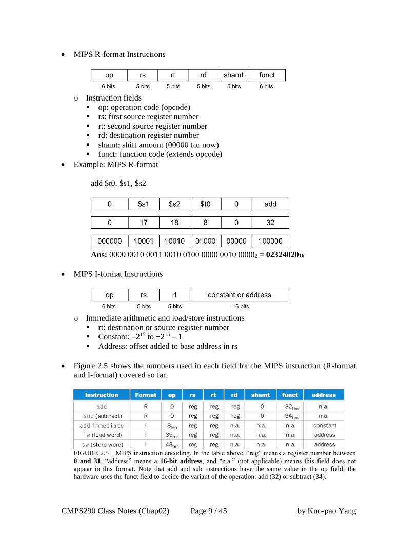
MIPS R-format Instructions
o Instruction fields
op: operation code (opcode)
rs: first source register number
rt: second source register number
rd: destination register number
shamt: shift amount (00000 for now)
funct: function code (extends opcode)
Example: MIPS R-format
add $t0, $s1, $s2
Ans: 0000 0010 0011 0010 0100 0000 0010 00002 = 0232402016
MIPS I-format Instructions
o Immediate arithmetic and load/store instructions
rt: destination or source register number
Constant: –215 to +215 – 1
Address: offset added to base address in rs
Figure 2.5 shows the numbers used in each field for the MIPS instruction (R-format
and I-format) covered so far.
FIGURE 2.5 MIPS instruction encoding. In the table above, “reg” means a register number between
0 and 31, “address” means a 16-bit address, and “n.a.” (not applicable) means this field does not
appear in this format. Note that add and sub instructions have the same value in the op field; the
hardware uses the funct field to decide the variant of the operation: add (32) or subtract (34).
CMPS290 Class Notes (Chap02) Page 10 / 45 by Kuo-pao Yang
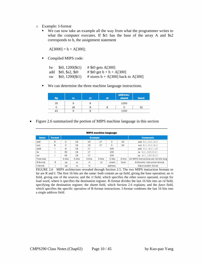
o Example: I-format
We can now take an example all the way from what the programmer writes to
what the computer executes. If $t1 has the base of the array A and $s2
corresponds to h, the assignment statement
A[3000] = h + A[300];
Compiled MIPS code:
lw $t0, 1200($t1) # $t0 gets A[300]
add $t0, $s2, $t0 # $t0 get h + h + A[300]
sw $t0, 1200($t1) # stores h + A[300] back to A[300]
We can determine the three machine language instructions.
Figure 2.6 summarized the portion of MIPS machine language in this section
FIGURE 2.6 MIPS architecture revealed through Section 2.5. The two MIPS instruction formats so
far are R and I. The first 16 bits are the same: both contain an op field, giving the base operation; an rs
field, giving one of the sources; and the rt field, which specifies the other source operand, except for
load word, where it specifies the destination register. R-format divides the last 16 bits into an rd field,
specifying the destination register; the shamt field, which Section 2.6 explains; and the funct field,
which specifies the specific operation of R-format instructions. I-format combines the last 16 bits into
a single address field.
CMPS290 Class Notes (Chap02) Page 11 / 45 by Kuo-pao Yang
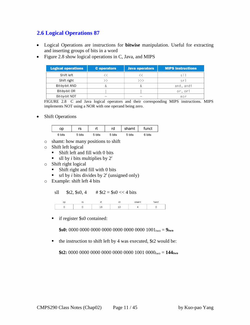
2.6 Logical Operations 87
Logical Operations are instructions for bitwise manipulation. Useful for extracting
and inserting groups of bits in a word
Figure 2.8 show logical operations in C, Java, and MIPS
FIGURE 2.8 C and Java logical operators and their corresponding MIPS instructions. MIPS
implements NOT using a NOR with one operand being zero.
Shift Operations
o shamt: how many positions to shift
o Shift left logical
Shift left and fill with 0 bits
sll by i bits multiplies by 2i
o Shift right logical
Shift right and fill with 0 bits
srl by i bits divides by 2i (unsigned only)
o Example: shift left 4 bits
sll $t2, $s0, 4 # $t2 = $s0 << 4 bits
if register $s0 contained:
$s0: 0000 0000 0000 0000 0000 0000 0000 1001two = 9two
the instruction to shift left by 4 was executed, $t2 would be:
$t2: 0000 0000 0000 0000 0000 0000 1001 0000two = 144two

CMPS290 Class Notes (Chap02) Page 12 / 45 by Kuo-pao Yang
AND Operations
o Useful to mask bits in a word.
Select some bits, clear others to 0
o Example: AND
and $t0, $t1, $t2 # $t0 = $t1 & $t2
$t1 masks (selects) 4 bits in $t2
OR Operations
o Useful to include bits in a word
Set some bits to 1, leave others unchanged
o Example: OR
or $t0, $t1, $t2 # $t0 = $t1 | $t2
$t1 includes (sets) 4 bits in $t2
NOT Operations
o Useful to invert bits in a word
Change 0 to 1, and 1 to 0
o MIPS has NOR 3-operand instruction
a NOR b == NOT (a OR b)
o Example: NOT
nor $t0, $t1, $zero # $t0 = ~ ($t1 | $zero)
$t0 = NOT $t1
CMPS290 Class Notes (Chap02) Page 13 / 45 by Kuo-pao Yang
2.7 Instructions for Making Decisions 90
MIPS assembly language includes two decision-making instructions, similar to an if
statement with a goto: beq and bne
Branch to a labeled instruction if a condition is true. Otherwise, continue sequentially
beq: Brach equal
beq rs, rt, L1 # if (rs == rt) branch to instruction labeled L1
bne: Brach not equal
bne rs, rt, L1 # if (rs /= rt) branch to instruction labeled L1
j: Jump
j L1 # Unconditional jump to instruction labeled L1
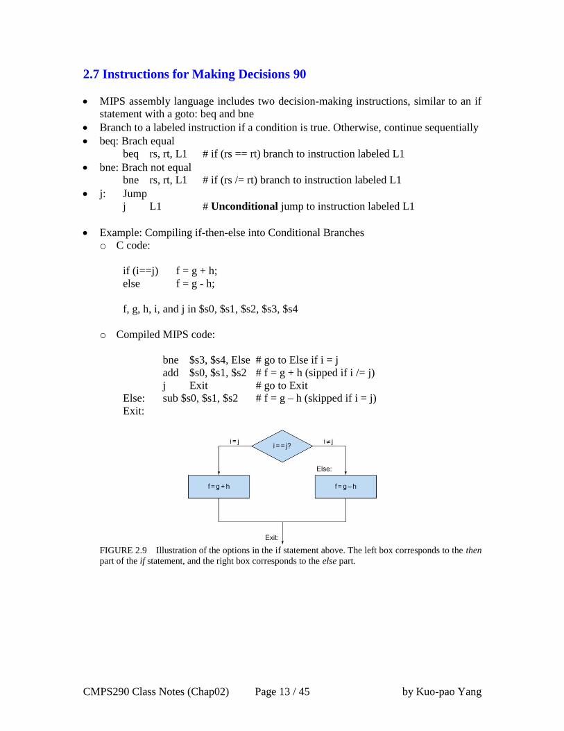
Example: Compiling if-then-else into Conditional Branches
o C code:
if (i==j) f = g + h;
else f = g - h;
f, g, h, i, and j in $s0, $s1, $s2, $s3, $s4
o Compiled MIPS code:
bne $s3, $s4, Else # go to Else if i = j
add $s0, $s1, $s2 # f = g + h (sipped if i /= j)
j Exit # go to Exit
Else: sub $s0, $s1, $s2 # f = g – h (skipped if i = j)
Exit:
FIGURE 2.9 Illustration of the options in the if statement above. The left box corresponds to the then
part of the if statement, and the right box corresponds to the else part.
CMPS290 Class Notes (Chap02) Page 14 / 45 by Kuo-pao Yang
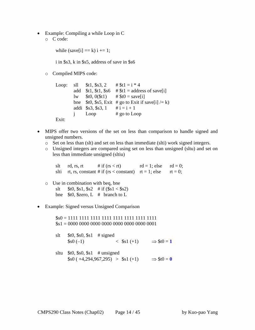
Example: Compiling a while Loop in C
o C code:
while (save[i] == k) i += 1;
i in $s3, k in $s5, address of save in $s6
o Compiled MIPS code:
Loop: sll $t1, $s3, 2 # $t1 = i * 4
add $t1, $t1, $s6 # $t1 = address of save[i]
lw $t0, 0($t1) # $t0 = save[i]
bne $t0, $s5, Exit # go to Exit if save[i] /= k)
addi $s3, $s3, 1 # i = i + 1
j Loop # go to Loop
Exit:
MIPS offer two versions of the set on less than comparison to handle signed and
unsigned numbers.
o Set on less than (slt) and set on less than immediate (slti) work signed integers.
o Unsigned integers are compared using set on less than unsigned (sltu) and set on
less than immediate unsigned (sltiu)
slt rd, rs, rt # if (rs < rt) rd = 1; else rd = 0;
slti rt, rs, constant # if (rs < constant) rt = 1; else rt = 0;
o Use in combination with beq, bne
slt $t0, $s1, $s2 # if ($s1 < $s2)
bne $t0, $zero, L # branch to L
Example: Signed versus Unsigned Comparison
$s0 = 1111 1111 1111 1111 1111 1111 1111 1111
$s1 = 0000 0000 0000 0000 0000 0000 0000 0001
slt $t0, $s0, $s1 # signed
$s0 (–1) < $s1 (+1) $t0 = 1
sltu $t0, $s0, $s1 # unsigned
$s0 ( +4,294,967,295) > $s1 (+1) $t0 = 0
CMPS290 Class Notes (Chap02) Page 15 / 45 by Kuo-pao Yang
2.8 Supporting Procedures in Computer Hardware 96
A procedure or function is one tool programmer use to structure programs, both to
make them easier to understand and to allow code be reused.
MIPS software follow the following convention for procedure calling in allocating its
32 registers:
o $a0 - $a3: four argument registers in which to pass parameters
o $v0 - $v1: two value register in which to return values
o $ra: one return address register to return to the point of origin
Procedure Call Instructions: jal and jr
o MIPS assembly language includes an instruction just for the procedures: it jumps
to an address and simultaneously saves the address of the following instruction in
register $ra. The jump-and-link instruction (jal) is simple written:
jal ProcedureLabel
Address of following instruction put in $ra
Jumps to target address
o MIPS use jump register instruction (jr) to allow the procedure to return to the
proper address. An unconditional jump to the address specified in a register:
jr $ra
Copies $ra to program counter
The calling program or caller puts the parameter values in $a0 - $a3 and uses jal X to
jump to procedure X (sometimes named the callee). The callee then performs the
calculations, places the results in $v0 and $v1, and returns control the caller using jr
$ra.
Programmer counter (PC): The register containing the address of the instruction in
the program being excuted.
The jal instruction actually saves PC + 4 in register $ra to link to the following
instruction to set up the procedure return.
Using More Registers
The ideal data structure for spilling registers is a stack – a last-in-first-out queue.
A stack need a pointer to the most recently allocated address in the stack to show
where the next procedure should place the registers to be spilled or where old register
values are found. The stack pointer is adjusted by one word for each register that is
saved or restored.
MIPS software reserves register 29 for the stack pointer, giving it the obvious name
$sp.

CMPS290 Class Notes (Chap02) Page 16 / 45 by Kuo-pao Yang
Placing data onto the stack is called a push, and removing data from the stack is
called a pop.
Example: Compiling a C Procedure That Doesn’t Call Another Procedure
o C code:
int leaf_example (int g, h, i, j) {
int f;
f = (g + h) - (i + j);
return f;
}
The parameter variables g, h, i, and j correspond to the argument registers $a0,
$a1, $a2, $a3, and f correspond to $s0.
Result in $v0
o Compiled MIPS code:
leaf_example:
addi $sp, $sp, -4 # adjust stack to make room for save registers
sw $s0, 0($sp) # save register $s0 on stack for use afterwards
add $t0, $a0, $a1 # register $t0 contains g + h
add $t1, $a2, $a3 # register $t1 contains i + j
sub $s0, $t0, $t1 # f = $t0 - $t1, which is (g + h) - (i + j)
add $v0, $s0, $zero # returns f ($v0 = $s0 + 0)
lw $s0, 0($sp) # restore register $s0 for caller
addi $sp, $sp, 4 # adjust stack to delete save registers
jr $ra # jump back to calling routine
FIGURE 2.10 The values of the stack pointer and the stack (a) before, (b) during, and (c) after the
procedure call. The stack pointer always points to the “top” of the stack, or the last word in the stack in this
drawing.
MIPS software separates 18 of the registers into two groups:
o $t0 - $t9: temporary registers that are not preserved by the callee (called
procedure) on a procedure
o $s0 - $s7: saved registers that must be preserved on a procedure call (if used, the
callee saved and restores them)
CMPS290 Class Notes (Chap02) Page 17 / 45 by Kuo-pao Yang
Nested Procedures
Procedure that do not calls others are called leaf procedure. Nested Procedures call
other procedurs.
For nested call, caller needs to save on the stack:
o Its return address $ra
o Any arguments ($a0 - $a3) and temporaries ($t0 =$t9) needed after the call
o Restore from the stack after the call
Example: Compiling a Recursive C Procedure, Showing Nest Procedure Linking.
o C code: recursive procedure that calculates factorial
int fact (int n) {
if (n < 1) return (1);
else return n * fact (n - 1);
}
Argument n in $a0
Result in $v0
o Compiled MIPS code:
fact: addi $sp, $sp, -8 # adjust stack for 2 items
sw $ra, 4($sp) # save the return address
sw $a0, 0($sp) # save the argument n
slti $t0, $a0, 1 # test for n < 1
beq $t0, $zero, L1 # if n >= 1, go to L1
addi $v0, $zero, 1 # if (n<1), result is 1
addi $sp, $sp, 8 # pop 2 items from stack
jr $ra # return to caller
L1: addi $a0, $a0, -1 # else n >= 1; agrument gets (n-1)
jal fact # call fact with (n-1)
lw $a0, 0($sp) # return from jal: restore original n
lw $ra, 4($sp) # restore the return address
addi $sp, $sp, 8 # adjust stack pointer to pop 2 items
mul $v0, $a0, $v0 # return n * fact (n-1)
jr $ra # and return to the caller
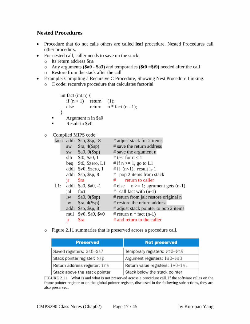
o Figure 2.11 summaries that is preserved across a procedure call.
FIGURE 2.11 What is and what is not preserved across a procedure call. If the software relies on the
frame pointer register or on the global pointer register, discussed in the following subsections, they are
also preserved.
CMPS290 Class Notes (Chap02) Page 18 / 45 by Kuo-pao Yang
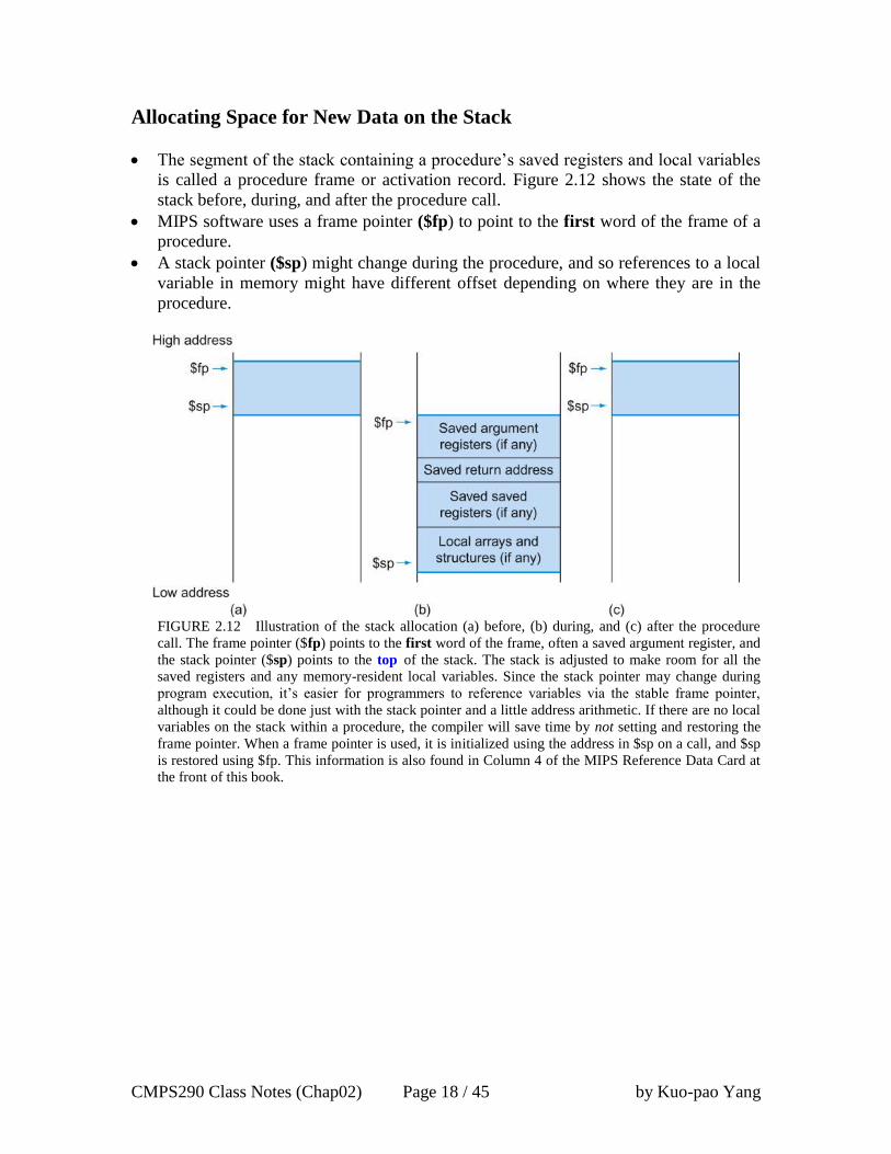
Allocating Space for New Data on the Stack
The segment of the stack containing a procedure’s saved registers and local variables
is called a procedure frame or activation record. Figure 2.12 shows the state of the
stack before, during, and after the procedure call.
MIPS software uses a frame pointer ($fp) to point to the first word of the frame of a
procedure.
A stack pointer ($sp) might change during the procedure, and so references to a local
variable in memory might have different offset depending on where they are in the
procedure.
FIGURE 2.12 Illustration of the stack allocation (a) before, (b) during, and (c) after the procedure
call. The frame pointer ($fp) points to the first word of the frame, often a saved argument register, and
the stack pointer ($sp) points to the top of the stack. The stack is adjusted to make room for all the
saved registers and any memory-resident local variables. Since the stack pointer may change during
program execution, it’s easier for programmers to reference variables via the stable frame pointer,
although it could be done just with the stack pointer and a little address arithmetic. If there are no local
variables on the stack within a procedure, the compiler will save time by not setting and restoring the
frame pointer. When a frame pointer is used, it is initialized using the address in $sp on a call, and $sp
is restored using $fp. This information is also found in Column 4 of the MIPS Reference Data Card at
the front of this book.
CMPS290 Class Notes (Chap02) Page 19 / 45 by Kuo-pao Yang
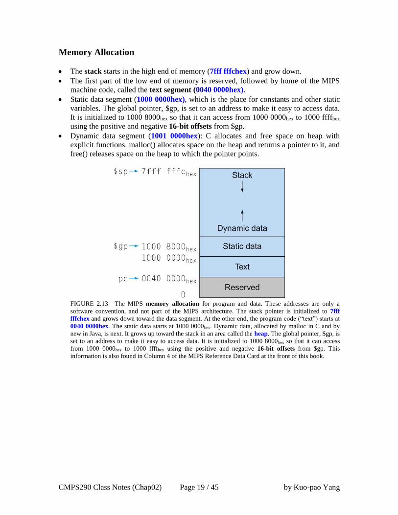
Memory Allocation
The stack starts in the high end of memory (7fff fffchex) and grow down.
The first part of the low end of memory is reserved, followed by home of the MIPS
machine code, called the text segment (0040 0000hex).
Static data segment (1000 0000hex), which is the place for constants and other static
variables. The global pointer, $gp, is set to an address to make it easy to access data.
It is initialized to 1000 8000hex so that it can access from 1000 0000hex to 1000 ffffhex
using the positive and negative 16-bit offsets from $gp.
Dynamic data segment (1001 0000hex): C allocates and free space on heap with
explicit functions. malloc() allocates space on the heap and returns a pointer to it, and
free() releases space on the heap to which the pointer points.
FIGURE 2.13 The MIPS memory allocation for program and data. These addresses are only a
software convention, and not part of the MIPS architecture. The stack pointer is initialized to 7fff
fffchex and grows down toward the data segment. At the other end, the program code (“text”) starts at
0040 0000hex. The static data starts at 1000 0000hex. Dynamic data, allocated by malloc in C and by
new in Java, is next. It grows up toward the stack in an area called the heap. The global pointer, $gp, is
set to an address to make it easy to access data. It is initialized to 1000 8000hex so that it can access
from 1000 0000hex to 1000 ffffhex using the positive and negative 16-bit offsets from $gp. This
information is also found in Column 4 of the MIPS Reference Data Card at the front of this book.

CMPS290 Class Notes (Chap02) Page 20 / 45 by Kuo-pao Yang
MIPS Register Conventions
Figure 2.14 summarize the register conventions for MIPS assembly language.
Most procedure can be satisfied with up to 4 arguments, 2 registers for a return value,
8 saved registers, and 10 temporary register without ever going to memory.
FIGURE 2.14 MIPS register conventions. Register 1, called $at, is reserved for the assembler (see
Section 2.12), and registers 26–27, called $k0–$k1, are reserved for the operating system. This
information is also found in Column 2 of the MIPS Reference Data Card at the front of this book.
CMPS290 Class Notes (Chap02) Page 21 / 45 by Kuo-pao Yang
2.9 Communicating with People 106
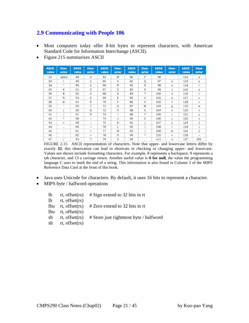
Most computers today offer 8-bit bytes to represent characters, with American
Standard Code for Information Interchange (ASCII).
Figure 215 summarizes ASCII
FIGURE 2.15 ASCII representation of characters. Note that upper- and lowercase letters differ by
exactly 32; this observation can lead to shortcuts in checking or changing upper- and lowercase.
Values not shown include formatting characters. For example, 8 represents a backspace, 9 represents a
tab character, and 13 a carriage return. Another useful value is 0 for null, the value the programming
language C uses to mark the end of a string. This information is also found in Column 3 of the MIPS
Reference Data Card at the front of this book.
Java uses Unicode for characters. By default, it uses 16 bits to represent a character.
MIPS byte / halfword operations
lb rt, offset(rs) # Sign extend to 32 bits in rt
lh rt, offset(rs)
lbu rt, offset(rs) # Zero extend to 32 bits in rt
lhu rt, offset(rs)
sb rt, offset(rs) # Store just rightmost byte / halfword
sh rt, offset(rs)
CMPS290 Class Notes (Chap02) Page 22 / 45 by Kuo-pao Yang
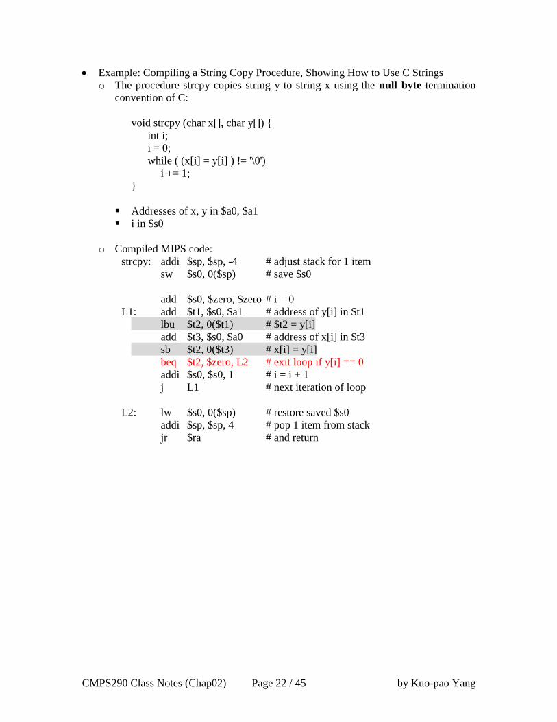
Example: Compiling a String Copy Procedure, Showing How to Use C Strings
o The procedure strcpy copies string y to string x using the null byte termination
convention of C:
void strcpy (char x[], char y[]) {
int i;
i = 0;
while ( (x[i] = y[i] ) != '\0')
i += 1;
}
Addresses of x, y in $a0, $a1
i in $s0
o Compiled MIPS code:
strcpy: addi $sp, $sp, -4 # adjust stack for 1 item
sw $s0, 0($sp) # save $s0
add $s0, $zero, $zero # i = 0
L1: add $t1, $s0, $a1 # address of y[i] in $t1
lbu $t2, 0($t1) # $t2 = y[i]
add $t3, $s0, $a0 # address of x[i] in $t3
sb $t2, 0($t3) # x[i] = y[i]
beq $t2, $zero, L2 # exit loop if y[i] == 0
addi $s0, $s0, 1 # i = i + 1
j L1 # next iteration of loop
L2: lw $s0, 0($sp) # restore saved $s0
addi $sp, $sp, 4 # pop 1 item from stack
jr $ra # and return
CMPS290 Class Notes (Chap02) Page 23 / 45 by Kuo-pao Yang
2.10 MIPS Addressing for 32-Bit Immediates and Addresses 111
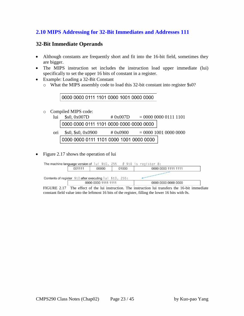
32-Bit Immediate Operands
Although constants are frequently short and fit into the 16-bit field, sometimes they
are bigger.
The MIPS instruction set includes the instruction load upper immediate (lui)
specifically to set the upper 16 bits of constant in a register.
Example: Loading a 32-Bit Constant
o What the MIPS assembly code to load this 32-bit constant into register $s0?
o Compiled MIPS code:
lui $s0, 0x007D # 0x007D = 0000 0000 0111 1101
ori $s0, $s0, 0x0900 # 0x0900 = 0000 1001 0000 0000
Figure 2.17 shows the operation of lui
FIGURE 2.17 The effect of the lui instruction. The instruction lui transfers the 16-bit immediate
constant field value into the leftmost 16 bits of the register, filling the lower 16 bits with 0s.
CMPS290 Class Notes (Chap02) Page 24 / 45 by Kuo-pao Yang
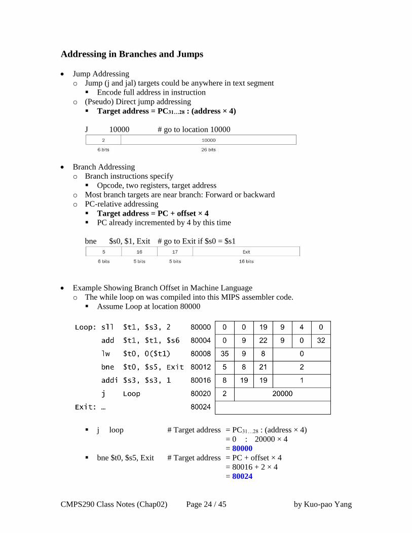
Addressing in Branches and Jumps
Jump Addressing
o Jump (j and jal) targets could be anywhere in text segment
Encode full address in instruction
o (Pseudo) Direct jump addressing
Target address = PC31…28 : (address × 4)
J 10000 # go to location 10000
Branch Addressing
o Branch instructions specify
Opcode, two registers, target address
o Most branch targets are near branch: Forward or backward
o PC-relative addressing
Target address = PC + offset × 4
PC already incremented by 4 by this time
bne $s0, $1, Exit # go to Exit if $s0 = $s1
Example Showing Branch Offset in Machine Language
o The while loop on was compiled into this MIPS assembler code.
Assume Loop at location 80000
j loop # Target address = PC31…28 : (address × 4)
= 0 : 20000 × 4
= 80000
bne $t0, $s5, Exit # Target address = PC + offset × 4
= 80016 + 2 × 4
= 80024

CMPS290 Class Notes (Chap02) Page 25 / 45 by Kuo-pao Yang
Branching Far Away
Most condition braches are to a nearby location, but occasionally they branch far
away, farther than can be represented in the 16 bits of the condition branch instruction.
The assembler comes to the rescue just as it did with large address or constants: it
inserts an unconditional jump to the branch target, and inverts the condition so that
the branch decides whether to skip the jump.
Example: Branching Far Away
o Giving a branch on register $s0 being equal to register $s1
beq $s0, $s1, L1
o If branch target is too far to encode with 16-bit offset, assembler rewrites the
code:
bne $s0, $s1, L2
j L1
L2: …
CMPS290 Class Notes (Chap02) Page 26 / 45 by Kuo-pao Yang
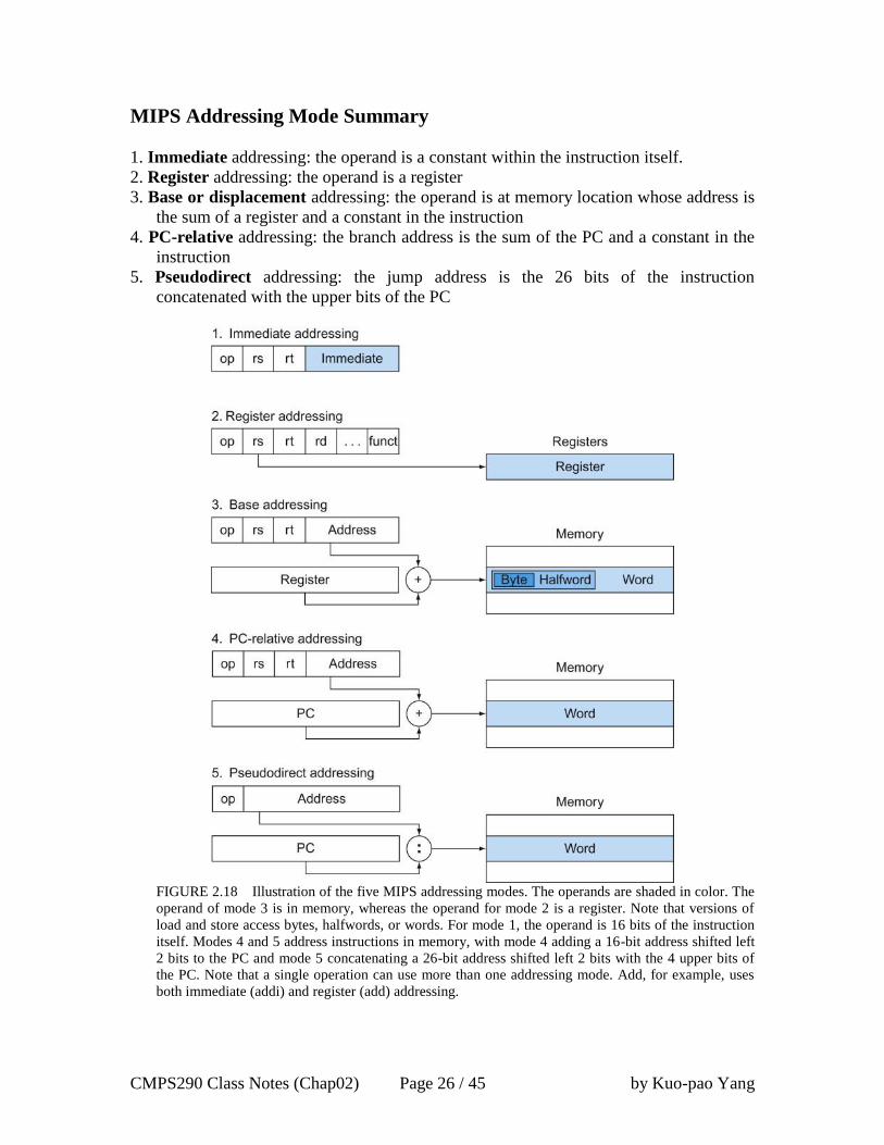
MIPS Addressing Mode Summary
1. Immediate addressing: the operand is a constant within the instruction itself.
2. Register addressing: the operand is a register
3. Base or displacement addressing: the operand is at memory location whose address is
the sum of a register and a constant in the instruction
4. PC-relative addressing: the branch address is the sum of the PC and a constant in the
instruction
5. Pseudodirect addressing: the jump address is the 26 bits of the instruction
concatenated with the upper bits of the PC
FIGURE 2.18 Illustration of the five MIPS addressing modes. The operands are shaded in color. The
operand of mode 3 is in memory, whereas the operand for mode 2 is a register. Note that versions of
load and store access bytes, halfwords, or words. For mode 1, the operand is 16 bits of the instruction
itself. Modes 4 and 5 address instructions in memory, with mode 4 adding a 16-bit address shifted left
2 bits to the PC and mode 5 concatenating a 26-bit address shifted left 2 bits with the 4 upper bits of
the PC. Note that a single operation can use more than one addressing mode. Add, for example, uses
both immediate (addi) and register (add) addressing.
CMPS290 Class Notes (Chap02) Page 27 / 45 by Kuo-pao Yang
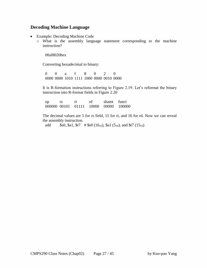
Decoding Machine Language
Example: Decoding Machine Code
o What is the assembly language statement corresponding to the machine
instruction?
00af8020hex
Converting hexadecimal to binary:
0 0 a f 8 0 2 0
0000 0000 1010 1111 1000 0000 0010 0000
It is R-formation instructions referring to Figure 2.19. Let’s reformat the binary
instruction into R-format fields in Figure 2.20
op rs rt rd shamt funct
000000 00101 01111 10000 00000 100000
The decimal values are 5 for rs field, 15 for rt, and 16 for rd. Now we can reveal
the assembly instruction.
add $s0, $a1, $t7 # $s0 (1610), $a1 (510), and $t7 (1510)
CMPS290 Class Notes (Chap02) Page 28 / 45 by Kuo-pao Yang
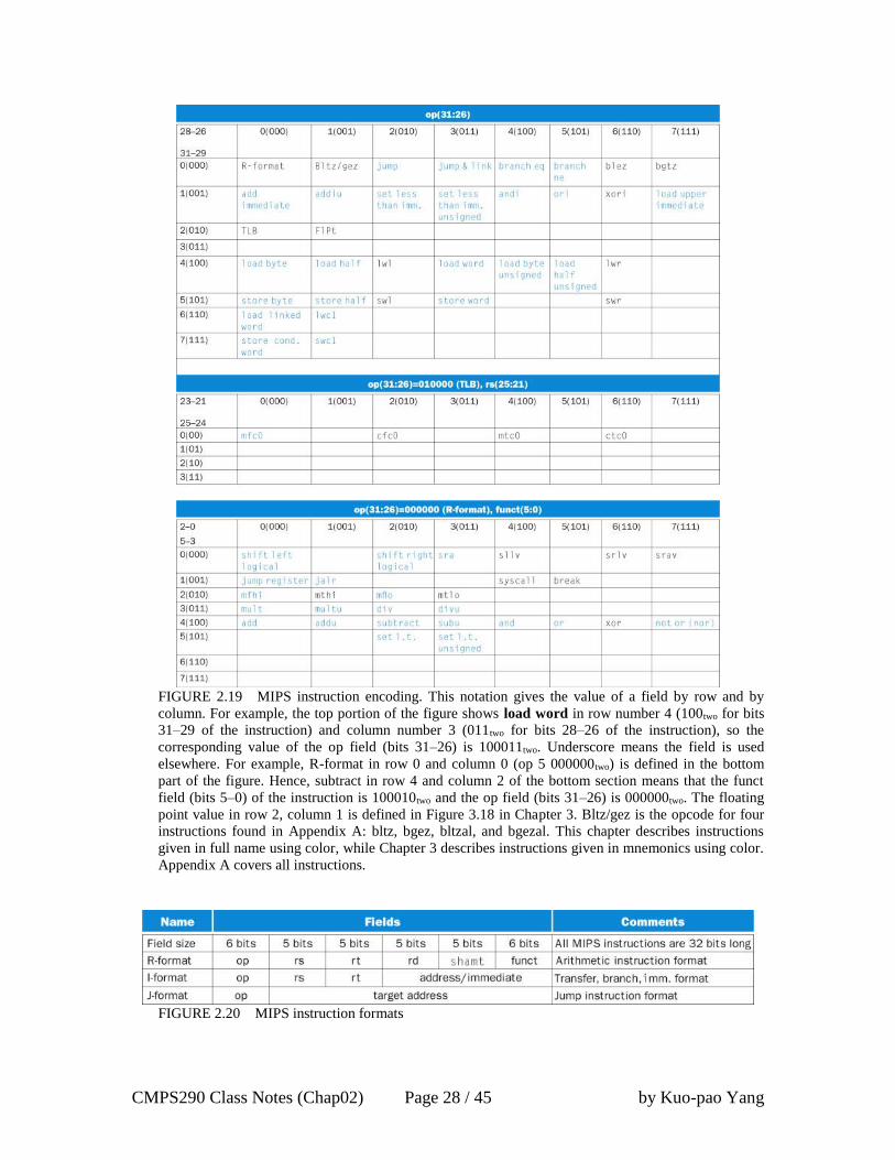
FIGURE 2.19 MIPS instruction encoding. This notation gives the value of a field by row and by
column. For example, the top portion of the figure shows load word in row number 4 (100two for bits
31–29 of the instruction) and column number 3 (011two for bits 28–26 of the instruction), so the
corresponding value of the op field (bits 31–26) is 100011two. Underscore means the field is used
elsewhere. For example, R-format in row 0 and column 0 (op 5 000000two) is defined in the bottom
part of the figure. Hence, subtract in row 4 and column 2 of the bottom section means that the funct
field (bits 5–0) of the instruction is 100010two and the op field (bits 31–26) is 000000two. The floating
point value in row 2, column 1 is defined in Figure 3.18 in Chapter 3. Bltz/gez is the opcode for four
instructions found in Appendix A: bltz, bgez, bltzal, and bgezal. This chapter describes instructions
given in full name using color, while Chapter 3 describes instructions given in mnemonics using color.
Appendix A covers all instructions.
FIGURE 2.20 MIPS instruction formats
CMPS290 Class Notes (Chap02) Page 29 / 45 by Kuo-pao Yang
2.11 Parallelism and Instructions: Synchronization 121
Synchronization
o Two processors sharing an area of memory
P1 writes, then P2 reads
Data race if P1 and P2 don’t synchronize
Result depends of order of accesses
o Lock and unlock synchronization can nr used straightforwardly to create regions
where only a single processor can operate, call a mutual exclusion.
o Hardware support required
Atomic read/write memory operation
No other access to the location allowed between the read and write
o Could be a single instruction
Ex, atomic swap of register ↔ memory
Or an atomic pair of instructions
Synchronization in MIPS
o Load linked: ll rt, offset(rs)
o Store conditional: sc rt, offset(rs)
Succeeds if location not changed since the ll
Returns 1 in rt
Fails if location is changed
Returns 0 in rt
o Example: atomic swap (to test/set lock variable)
try: add $t0, $zero, $s4 # copy exchange value
ll $t1, 0($s1) # load linked
sc $t0, 0($s1) # store conditional
beq $t0, $zero, try # branch store fails
add $s4, $zero, $t1 # put load value in $s4
CMPS290 Class Notes (Chap02) Page 30 / 45 by Kuo-pao Yang
2.12 Translating and Starting a Program 123
Compiler
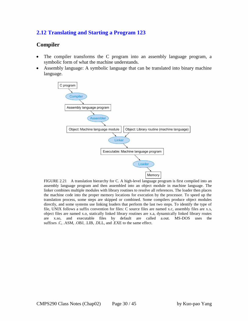
The compiler transforms the C program into an assembly language program, a
symbolic form of what the machine understands.
Assembly language: A symbolic language that can be translated into binary machine
language.
FIGURE 2.21 A translation hierarchy for C. A high-level language program is first compiled into an
assembly language program and then assembled into an object module in machine language. The
linker combines multiple modules with library routines to resolve all references. The loader then places
the machine code into the proper memory locations for execution by the processor. To speed up the
translation process, some steps are skipped or combined. Some compilers produce object modules
directly, and some systems use linking loaders that perform the last two steps. To identify the type of
file, UNIX follows a suffix convention for files: C source files are named x.c, assembly files are x.s,
object files are named x.o, statically linked library routines are x.a, dynamically linked library routes
are x.so, and executable files by default are called a.out. MS-DOS uses the
suffixes .C, .ASM, .OBJ, .LIB, .DLL, and .EXE to the same effect.
CMPS290 Class Notes (Chap02) Page 31 / 45 by Kuo-pao Yang
Assembler
The assembler converts this assembly language instruction into the machine language.
Pseudoinstruction: A common variation of assembly language instruction often
treated as if it were an instruction in its own right.
o The MIPS assembler accepts this instruction even though it is not found in the
MIPS architecture. The MIPS assembler converts move into add instruction.
move $t0, $t1 → add $t0, $zero, $t1
o The MIPS assembler also converts blt (branch on less than) into the two
instructions slt and bne.
blt $t0, $t1, L → slt $at, $t0, $t1
bne $at, $zero, L
o Other examples include bqt, bge, and ble
Pseudoinstructions give MIPS a richer set of assembly language instruction than
those implemented by the hardware.
Symbol table: A table that matches names of labels to the address of the memory
words that instruction occupy.
Assembler keep track of labels used in branches and data transfer instructions in a
symbol table.
Linker
Linker: Also called link editor. A systems program that combines independently
assembled machine language programs and resolves all undefined labels into an
executable file.
Executable file: A functional program in the format of an object file that contains no
unresolved references. It can contain symbol tables and debugging information.
Loader
Loader: A systems program that places an object program in main memory so that it
is ready to execute.
The executable file is on disk the operating system reads it to memory and start it.
Load from image file on disk into memory
CMPS290 Class Notes (Chap02) Page 32 / 45 by Kuo-pao Yang
Dynamically Linked Libraries (DLL)
Dynamically linked libraries (DLLs): Library routines that are linked to a program
during execution.
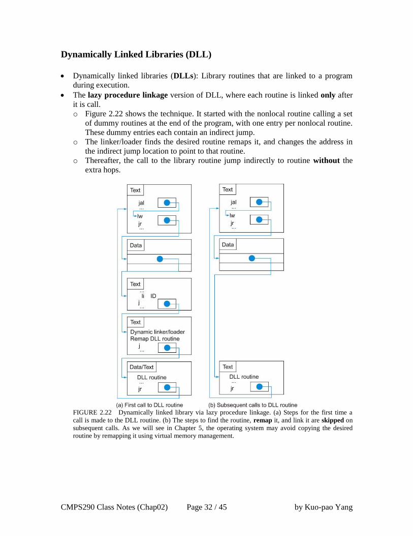
The lazy procedure linkage version of DLL, where each routine is linked only after
it is call.
o Figure 2.22 shows the technique. It started with the nonlocal routine calling a set
of dummy routines at the end of the program, with one entry per nonlocal routine.
These dummy entries each contain an indirect jump.
o The linker/loader finds the desired routine remaps it, and changes the address in
the indirect jump location to point to that routine.
o Thereafter, the call to the library routine jump indirectly to routine without the
extra hops.
FIGURE 2.22 Dynamically linked library via lazy procedure linkage. (a) Steps for the first time a
call is made to the DLL routine. (b) The steps to find the routine, remap it, and link it are skipped on
subsequent calls. As we will see in Chapter 5, the operating system may avoid copying the desired
routine by remapping it using virtual memory management.
CMPS290 Class Notes (Chap02) Page 33 / 45 by Kuo-pao Yang
Starting a Java Program
Java is compiled first to instructions that are easy to interpret; the Java bytecode
instruction set.
A software interpreter, called a Java Virtual Machine (JVM), can execute Java
bytecode.
The downside of interpretation is lower performance.
Just In Time compiler (JIT): The name commonly given to a compiler that operates
at runtime, translating the interpreted code segments into the native code of the
computer.
To preserve portability and improve execution speed, the next phase of Java
development was compilers that translated while the program was running.
Just In Time compiler (JIT) typically profile the running program to find where the
“hot” methods are and then compile them into the native instruction set on which the
virtual machine is running.
The compiled portion is saved for the next time the program is run, so that it can run
faster each time it is run.
Java on the fly, the performance gap between Java and C or C++ is closing.
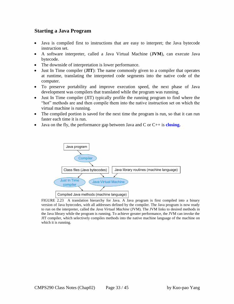
FIGURE 2.23 A translation hierarchy for Java. A Java program is first compiled into a binary
version of Java bytecodes, with all addresses defined by the compiler. The Java program is now ready
to run on the interpreter, called the Java Virtual Machine (JVM). The JVM links to desired methods in
the Java library while the program is running. To achieve greater performance, the JVM can invoke the
JIT compiler, which selectively compiles methods into the native machine language of the machine on
which it is running.
CMPS290 Class Notes (Chap02) Page 34 / 45 by Kuo-pao Yang
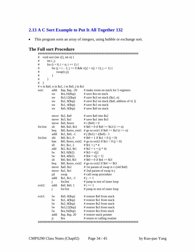
2.13 A C Sort Example to Put It All Together 132
This program sorts an array of integers, using bubble or exchange sort.
The Full sort Procedure ###############################################################
# void sort (int v[], int n) {
# int i, j;
# for (i = 0; i < n; i += 1) {
# for (j = i – 1; j >= 0 && v[j] > v[j + 1]; j -= 1) {
# swap(v,j);
# }
# }
# }
# v in $a0, n in $a1, i in $s0, j in $s1
sort: addi $sp, $sp, -20 # make room on stack for 5 registers
sw $ra,16($sp) # save $ra on stack
sw $s3,12($sp) # save $s3 on stack ($a1, n)
sw $s2, 8($sp) # save $s2 on stack ($a0, address of v[ ])
sw $s1, 4($sp) # save $s1 on stack
sw $s0, 0($sp) # save $s0 on stack
move $s2, $a0 # save $a0 into $s2
move $s3, $a1 # save $a1 into $s3
move $s0, $zero # i ($s0) = 0
for1tst: slt $t0, $s0, $s3 # $t0 = 0 if $s0 >= $s3 (i >= n)
beq $t0, $zero, exit1 # go to exit1 if $s0 >= $s3 (i >= n)
addi $s1, $s0, -1 # j ($s1) = i($s0) - 1
for2tst: slti $t0, $s1, 0 # $t0 = 1 if $s1 < 0 (j < 0)
bne $t0, $zero, exit2 # go to exit2 if $s1 < 0 (j < 0)
sll $t1, $s1, 2 # $t1 = j * 4
add $t2, $s2, $t1 # $t2 = v + (j * 4)
lw $t3, 0($t2) # $t3 = v[j]
lw $t4, 4($t2) # $t4 = v[j + 1]
slt $t0, $t4, $t3 # $t0 = 0 if $t4 >= $t3
beq $t0, $zero, exit2 # go to exit2 if $t4 >= $t3
move $a0, $s2 # 1st param of swap is v (old $a0)
move $a1, $s1 # 2nd param of swap is j
jal swap # call swap procedure
addi $s1, $s1, -1 # j –= 1
j for2tst # jump to test of inner loop
exit2: addi $s0, $s0, 1 # i += 1
j for1tst # jump to test of outer loop
exit1: lw $s0, 0($sp) # restore $s0 from stack
lw $s1, 4($sp) # restore $s1 from stack
lw $s2, 8($sp) # restore $s2 from stack
lw $s3,12($sp) # restore $s3 from stack
lw $ra,16($sp) # restore $ra from stack
addi $sp, $sp, 20 # restore stack pointer
jr $ra # return to calling routine
###############################################################
CMPS290 Class Notes (Chap02) Page 35 / 45 by Kuo-pao Yang
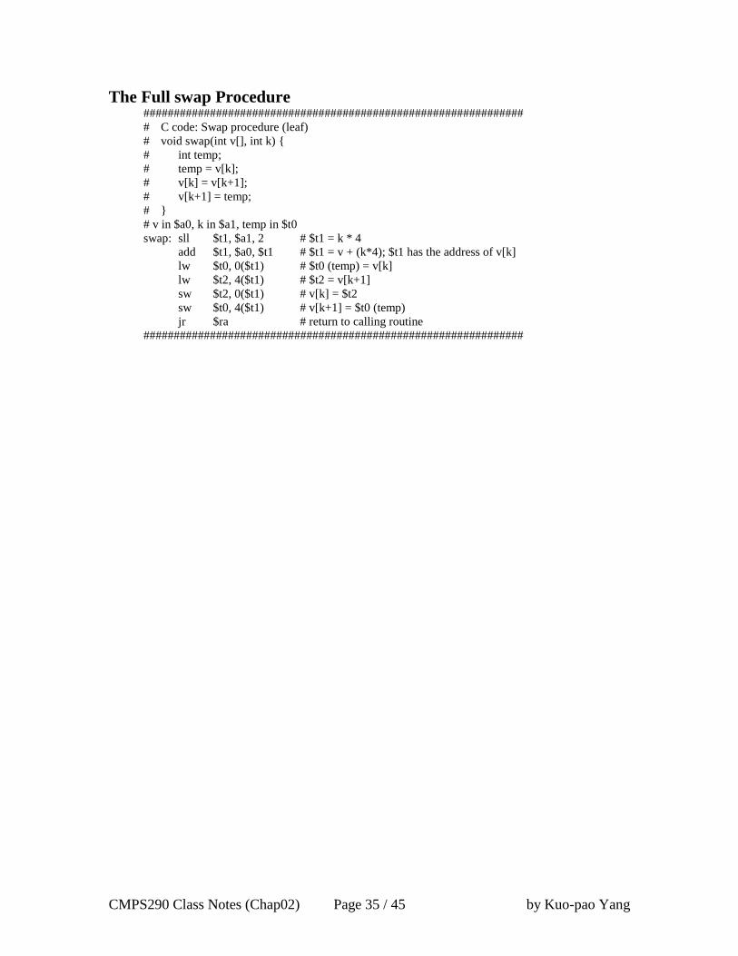
The Full swap Procedure ###############################################################
# C code: Swap procedure (leaf)
# void swap(int v[], int k) {
# int temp;
# temp = v[k];
# v[k] = v[k+1];
# v[k+1] = temp;
# }
# v in $a0, k in $a1, temp in $t0
swap: sll $t1, $a1, 2 # $t1 = k * 4
add $t1, $a0, $t1 # $t1 = v + (k*4); $t1 has the address of v[k]
lw $t0, 0($t1) # $t0 (temp) = v[k]
lw $t2, 4($t1) # $t2 = v[k+1]
sw $t2, 0($t1) # v[k] = $t2
sw $t0, 4($t1) # v[k+1] = $t0 (temp)
jr $ra # return to calling routine
###############################################################
CMPS290 Class Notes (Chap02) Page 36 / 45 by Kuo-pao Yang
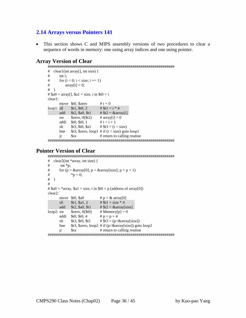
2.14 Arrays versus Pointers 141
This section shows C and MIPS assembly versions of two procedures to clear a
sequence of words in memory: one using array indices and one using pointer.
Array Version of Clear ###############################################################
# clear1(int array[], int size) {
# int i;
# for (i = 0; i < size; i += 1)
# array[i] = 0;
# }
# $a0 = array[], $a1 = size, i in $t0 = i
clear1:
move $t0, $zero # i = 0
loop1: sll $t1, $t0, 2 # $t1 = i * 4
add $t2, $a0, $t1 # $t2 = &array[i]
sw $zero, 0($t2) # array[i] = 0
addi $t0, $t0, 1 # i = i + 1
slt $t3, $t0, $a1 # $t3 = (i < size)
bne $t3, $zero, loop1 # if (i < size) goto loop1
jr $ra # return to calling routine
###############################################################
Pointer Version of Clear ###############################################################
# clear2(int *array, int size) {
# int *p;
# for (p = &array[0]; p < &array[size]; p = p + 1)
# *p = 0;
# }
#
# $a0 = *array, $a1 = size, i in $t0 = p (address of array[0])
clear2:
move $t0, $a0 # p = & array[0]
sll $t1, $a1, 2 # $t1 = size * 4
add $t2, $a0, $t1 # $t2 = &array[size]
loop2: sw $zero, 0($t0) # Memory[p] = 0
addi $t0, $t0, 4 # p = p + 4
slt $t3, $t0, $t2 # $t3 = (p<&array[size])
bne $t3, $zero, loop2 # if (p<&array[size]) goto loop2
jr $ra # return to calling routine
###############################################################
CMPS290 Class Notes (Chap02) Page 37 / 45 by Kuo-pao Yang
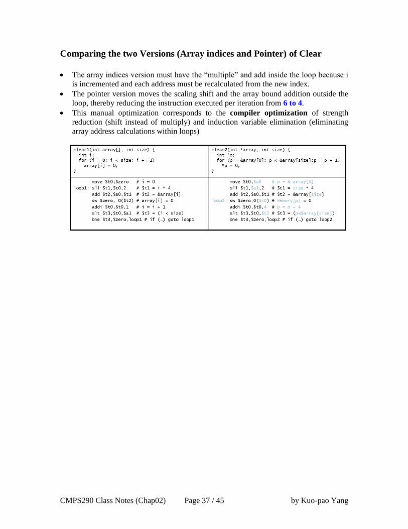
Comparing the two Versions (Array indices and Pointer) of Clear
The array indices version must have the “multiple” and add inside the loop because i
is incremented and each address must be recalculated from the new index.
The pointer version moves the scaling shift and the array bound addition outside the
loop, thereby reducing the instruction executed per iteration from 6 to 4.
This manual optimization corresponds to the compiler optimization of strength
reduction (shift instead of multiply) and induction variable elimination (eliminating
array address calculations within loops)
CMPS290 Class Notes (Chap02) Page 38 / 45 by Kuo-pao Yang
2.16 Real Stuff: ARM v7 (32-bit) Instructions 145
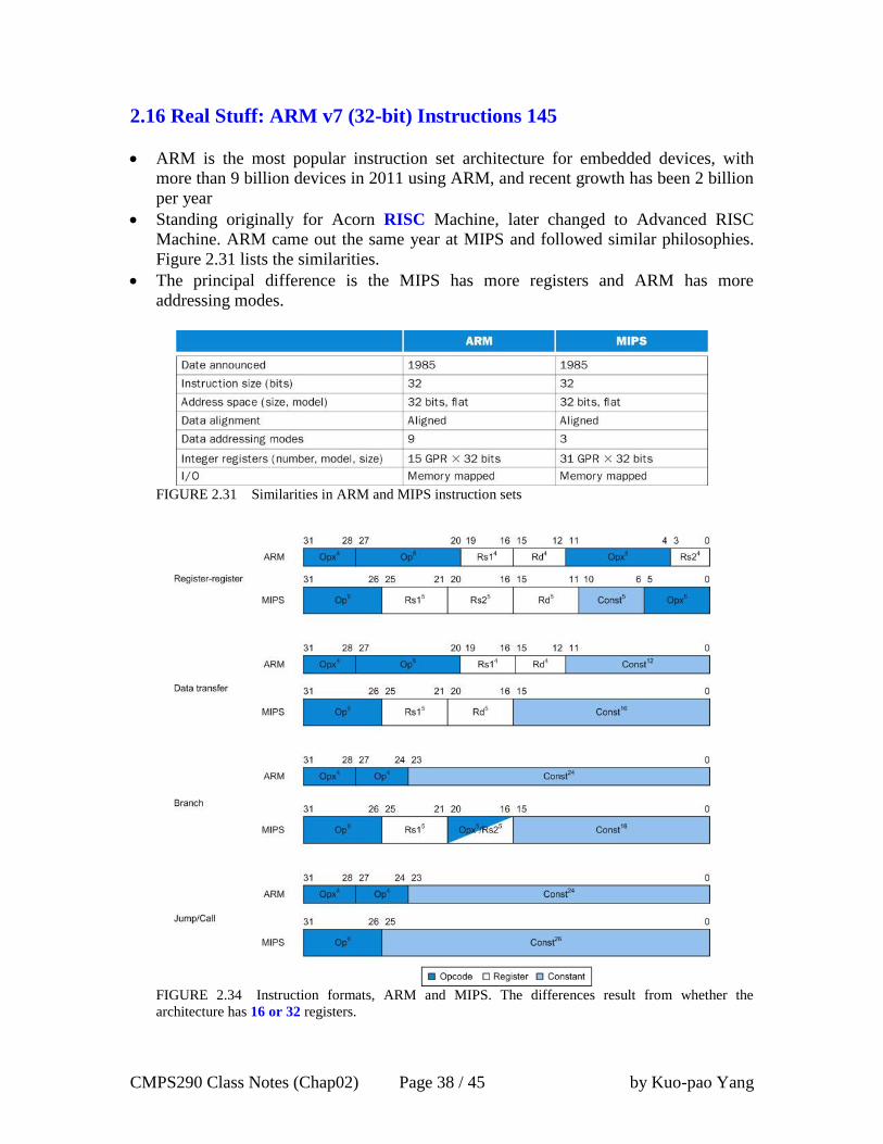
ARM is the most popular instruction set architecture for embedded devices, with
more than 9 billion devices in 2011 using ARM, and recent growth has been 2 billion
per year
Standing originally for Acorn RISC Machine, later changed to Advanced RISC
Machine. ARM came out the same year at MIPS and followed similar philosophies.
Figure 2.31 lists the similarities.
The principal difference is the MIPS has more registers and ARM has more
addressing modes.
FIGURE 2.31 Similarities in ARM and MIPS instruction sets
FIGURE 2.34 Instruction formats, ARM and MIPS. The differences result from whether the
architecture has 16 or 32 registers.
CMPS290 Class Notes (Chap02) Page 39 / 45 by Kuo-pao Yang
2.17 Real Stuff: x86 Instructions 149
Evolution with backward compatibility
8080 (1974): 8-bit microprocessor
o Accumulator, plus 3 index-register pairs
8086 (1978): 16-bit extension to 8080
o Complex instruction set (CISC)
8087 (1980): floating-point coprocessor
o Adds FP instructions and register stack
80286 (1982): 24-bit addresses, MMU
o Segmented memory mapping and protection
80386 (1985): 32-bit extension (now IA-32)
o Additional addressing modes and operations
o Paged memory mapping as well as segments
o Like the 80286, the 80386 has a compatibility mode to execute 8086 program
without change
80486 (1989): pipelined, on-chip caches and FPU
o Compatible competitors: AMD, Cyrix, …
Pentium (1993): superscalar, 64-bit datapath
o Later versions added MMX (Multi-Media eXtension) instructions
o The infamous FDIV bug
Pentium Pro (1995), Pentium II (1997)
o New microarchitecture (see Colwell, The Pentium Chronicles)
Pentium III (1999)
o Added SSE (Streaming SIMD Extensions) and associated registers
Pentium 4 (2001)
o New microarchitecture
o Added SSE2 instructions
AMD64 (2003): extended architecture to 64 bits
o Long mode: execution of all x86 instructions
EM64T (2004), Extended Memory 64 Technology
o AMD64 adopted by Intel (with refinements)
o Added SSE3 instructions
Intel Core (2006)
o Added SSE4 instructions, virtual machine support
AMD64 (2007): announced SSE5 instructions
Intel (2011): Advanced Vector Extension
o Longer SSE registers (128 to 256 bits), more instructions
If Intel didn’t extend with compatibility, its competitors would!
o Technical elegance ≠ market success

CMPS290 Class Notes (Chap02) Page 40 / 45 by Kuo-pao Yang
X86 Registers and Data Addressing Modes
Basic x86 Registers
o The registers of the 80386 extended all 16-bit register (except the segment
registers) to 32 bits such as EAX, EBX.
o The 80386 contains only 8 GPRs (general-purpose registers).
o The means MIPS program can use 4 times (32 registers) as many and ARMv7
twice (16 registers) as many.
o The 8086 provides support for both 8-bit (byte) and 16-bit (word) data type.
o The 80386 add 32-bit address and data (double words) in the x86.
FIGURE 2.36 The 80386 register set. Starting with the 80386, the top eight registers were extended
to 32 bits and could also be used as general-purpose registers.
Basic x86 Addressing Modes
FIGURE 2.37 Instruction types for the arithmetic, logical, and data transfer instructions. The x86
allows the combinations shown. The only restriction is the absence of a memory-memory mode.
Immediates may be 8, 16, or 32 bits in length; a register is any one of the 14 major registers in Figure
2.36 (not EIP or EFLAGS).

CMPS290 Class Notes (Chap02) Page 41 / 45 by Kuo-pao Yang
X86 Instruction Format
The encoding of instructions in the 80386 is complex, with many different instruction
formats.
Instructions for the 80386 may vary form 1 byte up to 15 bytes in length.
FIGURE 2.41 Typical x86 instruction formats. Figure 2.42 shows the encoding of the postbyte.
Many instructions contain the 1-bit field w, which says whether the operation is a byte or a double
word. The d field in MOV is used in instructions that may move to or from memory and shows the
direction of the move. The ADD instruction requires 32 bits for the immediate field, because in 32-bit
mode, the immediates are either 8 bits or 32 bits. The immediate field in the TEST is 32 bits long
because there is no 8-bit immediate for test in 32-bit mode. Overall, instructions may vary from 1 to 15
bytes in length. The long length comes from extra 1-byte prefixes, having both a 4-byte immediate
and a 4-byte displacement address, using an opcode of 2 bytes, and using the scaled index mode
specifier, which adds another byte.

CMPS290 Class Notes (Chap02) Page 42 / 45 by Kuo-pao Yang
Implementing IA-32
Complex instruction set makes implementation difficult
o Hardware translates instructions to simpler micro operations
Simple instructions: 1–1
Complex instructions: 1–many
Comparable performance to RISC
o Compilers avoid complex instructions
CMPS290 Class Notes (Chap02) Page 43 / 45 by Kuo-pao Yang
2.18 Real Stuff: ARM v8 (64-bit) Instructions 158
In moving to 64-bit, ARM did a complete overhaul
ARM v8 resembles MIPS
Changes from ARM v7:
o No conditional execution field
o Immediate field is 12-bit constant
o Dropped load/store multiple
o PC is no longer a GPR
o GPR set expanded to 32
o Addressing modes work for all word sizes
o Divide instruction
o Branch if equal/branch if not equal instructions
CMPS290 Class Notes (Chap02) Page 44 / 45 by Kuo-pao Yang
2.20 Concluding Remarks 161
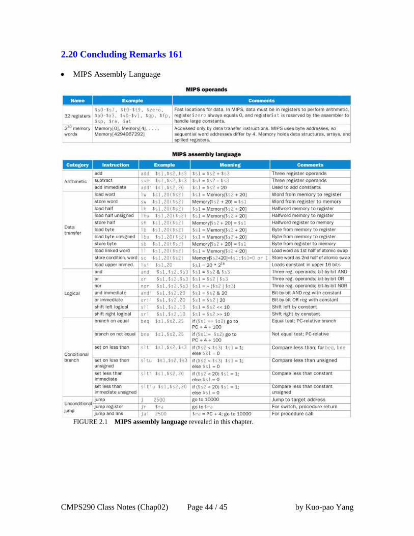
MIPS Assembly Language
FIGURE 2.1 MIPS assembly language revealed in this chapter.
CMPS290 Class Notes (Chap02) Page 45 / 45 by Kuo-pao Yang
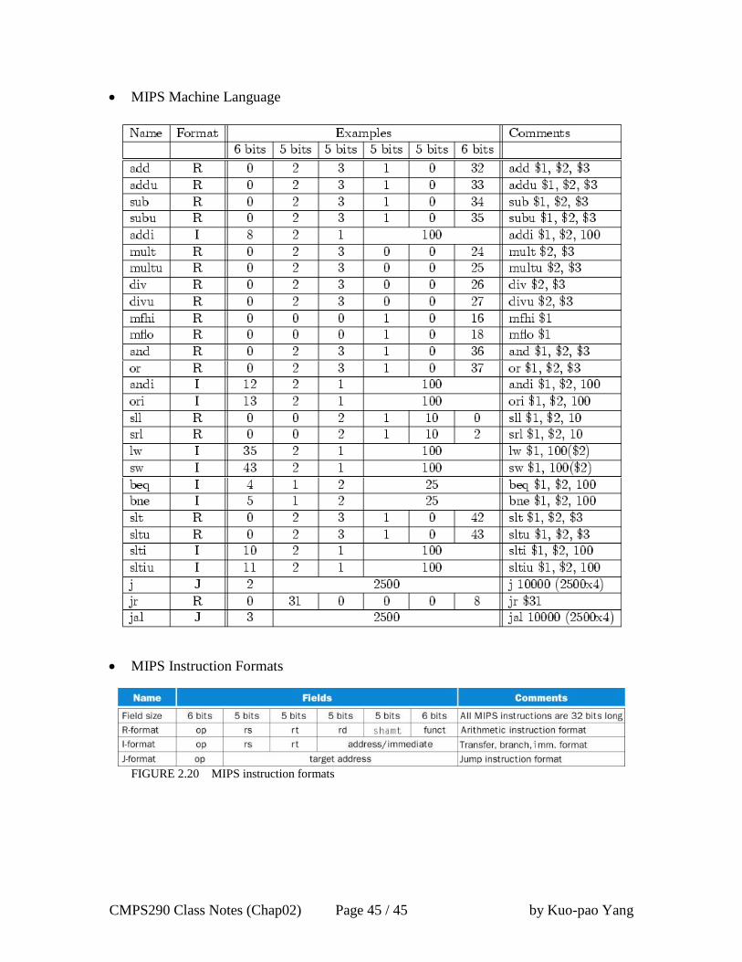
MIPS Machine Language
MIPS Instruction Formats
FIGURE 2.20 MIPS instruction formats