chapter 2 error control for interactive continuous media applications
TRANSCRIPT
15
Chapter 2
Error Control for Interactive ContinuousMedia Applications
In the previous chapter we characterized continuous media (CM) applications as applications
that have very strict timing requirements. We gave examples like audio and video applications,
which require periodic transmission of data (e.g., 30 frames per second for MPEG video), and
pointed out that the utility of such applications depends on the regular and timely delivery of data
in order to ensure a smooth presentation, free of annoying artifacts like image distortion and jump-
ing. While the strict timing requirements of CM applications make error control difficult, we also
pointed out that compression schemes like MPEG make error recovery even more important
because loss of a compressed data packet typically results in more information loss than loss of an
uncompressed packet. We made a distinction between interactive and stored media applications,
pointing out that error control in interactive CM applications is harder to implement than stored
media applications, because in the former data needs to be transmitted almost immediately after
generated to preserve the feeling of interaction. Long round-trip-times (RTT), like those experi-
enced in coast-to-coast communication, complicate error control even further because they limit the
time available for recovery.
At the time our work was published[85], it was commonly believed that retransmission-based
error recovery was inappropriate for interactive continuous media (CM) applications, because of
latency. However, we felt that retransmission was still an attractive option, because it requires min-
imal network bandwidth and processing cost, and argued that despite its latency, retransmission can
be adapted for use even in interactive CM applications.

16
In this chapter we present the design and implementation of a retransmission-based error con-
trol scheme for CM applications, which aims to provide the best possible reliability at a minimal
cost, without violating the application’s timing constraints. To achieve this goal, we have enhanced
selective-repeat retransmission with the following mechanisms: (1) playout buffering to increase
the time available for recovery; (2) gap-based rather than timer-based loss detection to minimize
loss detection latency; (3) implicit expiration of sender retransmission buffers to eliminate acknowl-
edgments; (4) conditional retransmission requests to avoid triggering late, unnecessary retransmis-
sions; and (5) data integrity information delivery to the application to aid in concealment. Our
experiments have shown that the mechanism significantly reduces observed loss without violating
the application’s delay constraints. For example, it has reduced observed loss by orders of magni-
tude for both random and bursty loss. We have implemented this protocol in the kernel of NetBSD
Unix, where it resides alongside popular Internet transport protocols like TCP and UDP.
The remainder of this chapter is organized as follows: in Section 2.1. we motivate the need for
error control for CM applications. In Section 2.2. we present background and related work. In Sec-
tion 2.3., we describe the features of our retransmission-based error control scheme that allow it to
support delay-sensitive CM applications without violating their timing constraints. Section 2.4. pre-
sents details of our implementation. In Section 2.5. we present experimental results on our local 155
Mbps ATM testbed. Section 2.6. describes our extensions to the scheme to support multiple retrans-
missions, which is part of future work. Finally, Section 2.7. presents our conclusions.
2.1. Requirements of Continuous Media Applications
Continuous media (CM) streams are characterized by periodic and relatively long lived (e.g.,
minutes, hours or more) data exchange. Examples of CM streams include video, audio, image ani-
mation, and others. The salient characteristics of CM streams are their periodicity and strict timing
requirements. Some CM streams (especially those carrying visual information, like video and ani-
mation) require very high bandwidth (>100 Mbps) if transmitted in raw form. To save on band-
width, such streams are often compressed, which leads to highly bursty, variable bit-rate (VBR)
output streams. Transmitting a VBR stream over packet switched networks is difficult without
packet loss due to congestion, or without wasting substantial bandwidth with a peak rate reserva-
tion. Moreover, compressed CM streams are far less tolerant to packet loss, because compression
17
eliminates a significant amount of redundancy present in the uncompressed data. In addition, com-
pressed data often contains control information (e.g, frame headers) whose loss may lead to misin-
terpretation or discarding of a large portion of otherwise correctly received data.
2.2. Avoiding Losses
To minimize network losses while maximizing the statistical multiplexing gain, several forms
of congestion control have been proposed. These methods include adapting the source bandwidth
according to congestion in the network [9], renegotiating the network reservations according to the
source requirements [19], creation of multiple concurrent streams with different rate/quality char-
acteristics [7], and hierarchically encoded streams [12]. These schemes are promising, even though
some require support from the entire network. Bandwidth adaptation in these methods is typically
not instantaneous, and thus some losses may still occur while the sources and the network settle to
a new congestion-free state. Losses may also be experienced due to other reasons not related to con-
gestion, like route changes, interference, etc. Thus, it is desirable for applications to complement
their congestion control method with some form of error control which can recover losses quickly,
to help achieve a graceful degradation of quality1.
Traditional error control schemes mostly use retransmission and provide 100% reliability at the
expense of latency. This is clearly the wrong model for CM applications, where late packets are as
good as lost packets. However, retransmission has been widely dismissed even as a method to do
partial recovery, in favor of other error control methods, including forward error correction (FEC)
and concealment. We believe that retransmission was dismissed without investigating its full poten-
tial. We briefly discuss our reasoning next.
2.2.1. Forward Error Correction (FEC)
FEC[8] has been proposed as an alternative to retransmission for CM applications. FEC is an
open-loop error control scheme that allows trading bandwidth for lower error rate while maintaining
latency close to the RTT. To perform FEC, appropriate redundant data is sent in addition to the
application’s original data. The redundant data is used at the receiver to reconstruct the original data
1. We assume that quality degrades more gracefully if lost data is recovered and the application sub-sequently reduces its data rate to control congestion.

18
in the event that a loss occurs. Thus, loss is recovered without any end-to-end exchange between the
sender and receiver, which makes FEC very attractive for applications with delay sensitive data.
However, finding a good bandwidth/loss compromise is not always easy: computing the amount of
redundancy and thus the bandwidth allocation for the FEC stream becomes difficult for bursty net-
work losses, because the redundancy is proportional to the longest burst loss, which is very hard to
predict. It is possible that the FEC bandwidth overhead required to recover bursty losses may be as
much as 25 - 30% [24]. Thus, FEC can be a costly solution for high bandwidth bursty CM applica-
tions (while admittedly this may not be true for low bandwidth CM streams like audio).
2.2.2. Concealment
Concealment [28] is not strictly an error control scheme because it does not actually recover
lost data, but rather creates an approximate reconstruction of the missing data based on available
information. Concealment is strictly receiver-based and does not require any end-to-end exchange.
Examples of concealment include substitution of lost data with data from an earlier frame, and var-
ious methods of interpolation and approximation. However, concealment creates artifacts, which
may be detectable by the user, depending on the amount of data lost, the type of stream and the
effectiveness of the concealment algorithm. High-quality concealment algorithms are expensive for
high bandwidth applications and may necessitate the use of specialized hardware. Finally, since the
effectiveness of concealment depends on the amount of available data, concealment becomes much
harder with bursty loss.
Unless 100% reliability can be guaranteed, we believe that some form of concealment will be
necessary at the receiver to hide the occasional unavoidable loss. However, there is a clear trade-off
between loss and the effectiveness of concealment (for a given concealment method), so even if
concealment is available, there is a strong incentive to keep losses low (perhaps by employing error
control) to reduce the cost of concealment and achieve graceful degradation.
2.2.3. Retransmission
Retransmission-based error recovery has been, in general, considered inappropriate for CM
applications. The main reason is that retransmission requires at least one additional round-trip time
(RTT) to recover lost packets, which may be unacceptable to CM applications. One commonly cited
example is that of a US coast-to-coast NTSC video stream, where retransmitting a packet requires

19
at least 40 - 60 ms, which is larger than the frame period (33 ms), and thus losses in a frame cannot
be recovered in time.
While not applicable to cases where the RTT is large, it has been shown that retransmission is
feasible in many cases where the RTT is relatively small (e.g., LANs and MANs), especially if a
playout buffer is used to increase the time available for recovery [15,26]. Despite its latency draw-
back, we believe that retransmission-based error control is still an attractive solution because of its
modest bandwidth and processing costs. For example, unlike FEC, retransmission requires network
bandwidth proportional to the loss rate, not the data rate. In addition, processing costs associated
with retransmission are low and all processing can be easily done in software (as we demonstrate
in this chapter). In fact, retransmission is still used in several high-speed protocols [16]. In contrast,
while some FEC encodings are simple and can be done in software (e.g. XOR), they involve data
touching which is expensive.
The playout buffer is an important component of any retransmission scheme aimed at a latency-
constrained environment, and is perhaps the most important difference with traditional retransmis-
sion schemes. However, as we argue later, the costs associated with the playout buffer are small. It
is important to note that the size of the playout buffer is a trade-off between the gain in recovery
time and the delay imposed on CM (especially interactive) applications. The playout delay in inter-
active applications is limited to a few hundred milliseconds, but this is still significantly larger than
the RTT in future LANs and MANs. Moreover, playout buffering can be made much larger in non-
interactive (e.g, stored media) applications, allowing perhaps enough time for several retransmis-
sion attempts. An example where large playout buffering is possible, is a regional video-on-demand
(VOD) entertainment server serving individual homes, where good video quality is essential.
Even if retransmission can be given enough recovery time to be feasible, other important ques-
tions remain to be answered. For example, how will retransmission react with congestion control?
Will the influx of retransmissions after a network loss period cause more congestion and more loss?
Can retransmission be used in a multicast environment in a scalable fashion? We will not attempt
to answer these questions in this chapter. Such questions require detailed studies which are beyond
the scope of this work. However, we will attempt to give qualitative justifications why we believe
that these problems can be solved.
20
The problem of interaction between retransmission and congestion is common to all retrans-
mission-based schemes. One way to tackle this problem is for the application to set aside some
bandwidth for retransmissions (as with FEC where the application reserves additional bandwidth
for the FEC encoding). During congestion the application reduces its rate enough so that the new
data plus retransmissions do not exceed the reservation (we again assume that delivering retrans-
missions, perhaps at the expense of reducing the rate of new data, is important, so that the stream
will degrade more gracefully). Unlike FEC, however, the retransmission bandwidth is not used most
of the time, which increases the statistical multiplexing gain in the network. In addition, as has been
observed in [26] the network loss periods may be so short that it is possible that by the time a
retransmission is injected in the network the congestion may have already cleared.
Retransmission typically does not scale very well in multicast environments without some form
of implosion control. However, retransmission has been shown to scale very well in multicast envi-
ronments where data can be recovered locally from other receivers in the multicast group
[25,22,17]. FEC is better suited for multicast because it does not suffer from implosion. However,
some problems still remain: the FEC encoding must contain enough redundancy to provide satis-
factory service to receivers who may see different loss rates, which may incur a significant band-
width overhead.
To summarize, we believe that retransmission-based error control, although not suited for all
CM applications, is still an attractive, low-cost solution and remains a serious candidate for CM
error control. Retransmission is well suited for most unicast stored media and many interactive
applications where the RTT is low, and for multicast applications if the right implosion control
framework is used. In special cases, retransmission can also be used in a multicast environments
with large RTT: for example, in a live multicast connection if some of the receivers act as media
recorders, they can still benefit from retransmissions even if they arrive too late to benefit other
receivers.
From the remaining related work on retransmission for CM, the work closest to ours is Partially
Reliable Streams [14]. We are not aware of any evaluation studies of PRS.

21
2.3. Making Retransmission Work
In order to minimize the retransmission bandwidth and latency we adopt selective repeat rather
than go-back-N retransmission. The appropriateness of selective repeat for high-speed networks has
been already demonstrated widely in literature [11,13,23]. To maximize the probability of recovery,
we have added the following features:
2.3.1. Playout buffering
The time available for recovery may be increased with no perceptible (to the user) deterioration
of quality, by introducing limited buffering at the receiver. This is called playout buffering and the
buffering delay is called playout or control delay. In interactive applications the playout delay is
limited by the perceptual tolerance of the user, which is around 200 ms [10]. In other words, a
human user can tolerate a maximum channel round-trip delay of 200 ms in an interactive conversa-
tion1. In interactive applications the delay must be allocated to both endpoints, meaning that each
may use up to 100 ms of playout delay. An example of using playout buffering is shown in Figure
2.1. We assume that frames are generated every 33 ms, so a playout buffer of up to three frames may
be used, which increases the time available for retransmission is by 99 ms. This is sufficient for sev-
eral retransmission attempts in LANs and MANs. Again, we note that the playout delay can be
1. This number is still debated. Some claim that this is actually a lot higher, perhaps as much as 400ms.
Figure 2.1: Playout buffering
tt + 33t + 66t + 99t + 132
TRANSMITTER RECEIVER
DisplayPlayout
t + tpt + tp + 33t + tp + 66t + tp + 99t + tp + 132
Retransmissionbufferbuffer

22
much larger in case of stored media retrieval (e.g., video-on-demand) without any adverse effect on
the perceived quality. It hardly matters to a viewer if the playback of a movie starts a few seconds
after the movie request, if a continuous, error-free playback can be guaranteed from that point on.
In practice the playout delay may be limited by the desired delay for control operations like fast-
forward, pause, etc., which is approximately 0.5 - 1 second.
The size of the playout buffer is fairly small in most cases. For example, buffering 3 frames of
NTSC compressed video (5 - 10 Mbps), requires a playout buffer of 62.5 - 125 kilobytes. For com-
pressed HDTV (about 20 Mbps), the size of the playout buffer for three frames is 250 kilobytes.
These numbers are well within the capabilities of modern workstations. Note that the digital frame
buffer itself is much larger than this. We believe that playout buffers of this size pose no problems
to television receivers and set-top boxes: some of today’s high-end television sets already have
enough memory to store frames for special effects (freeze-frame, slow motion, etc.).
2.3.2. Gap-based loss detection
Most transport protocols rely on timers to detect losses. In timer-based loss detection, the
sender associates each packet (or group of packets) with a timer. If the timer expires before an
acknowledgment is received, the packet is retransmitted. The time-out values are typically large
(several times the RTT), which adds significant delay to loss detection. Therefore, unless the timer
values can be determined very accurately, timer-based loss detection is not appropriate for contin-
uous media applications.
We believe that gap-based loss detection [18] at the receiver combined with NACKs is well-
suited to CM applications. In gap-based loss detection, each packet carries a sequence number. A
gap is detected when a packet arrives with a sequence number higher than expected. In gap-based
loss detection a gap is detected only after another packet is received. Therefore losses are detected
quickly if data is sent continuously (as in high-bandwidth CM applications), provided that burst
losses are not too large. Another advantage is that loss detection does not require per-packet timers.
It is important to note, however, that gap-based loss detection is applicable only if the underly-
ing network preserves packet sequencing. For networks that do not support FIFO delivery of data,
gap detection becomes more difficult, but may still be used if a decision is made about how many
out-of-sequence packets can be received before a packet is declared lost. Gap-based loss detection

23
may take longer than time-out loss detection during prolonged network loss periods. However,
sending a retransmission request before the network loss period is over may cause the request or the
retransmitted data to be lost again. With gap-based loss detection, loss is detected after a new packet
makes it through, so there is a good possibility that the network loss period is over (the use of RED
gateways[86] invalidates this remark).
2.3.3. Implicit expiration of sender retransmission buffers
We assume that the period of a CM stream is constant and the sender knows its value. We also
assume that the sender discovers the size of the receiver’s playout buffer during connection setup.
Using this information, the sender can estimate how long to keep data in its retransmission buffers
before the data expires and can be safely discarded. Therefore, an explicit ACK from the receiver
is not required to discard retransmission buffers. A simple way to implement this is for the sender
to maintain a retransmission buffer with the same number of slots as the receiver’s playout buffer.
Thus, whenever new data is sent the oldest data in the retransmission buffer can be discarded
because it has expired. Implicit data expiration eliminates delays associated with waiting for ACKs.
It also eliminates retransmission of packets that would arrive late: if a retransmission request is
delayed and arrives after the data has been discarded, no packets are retransmitted. Therefore the
sender need not check if packets will arrive at the receiver in time before it retransmits; the sender
simply retransmits if the requested data is still in the retransmission buffer.
2.3.4. Conditional retransmission requests
Since data in continuous media has a limited lifetime, there is no point requesting retransmis-
sion if the retransmitted packets will not arrive in time. In other words, retransmission should be
aborted if the time left before presentation is less than the RTT. This may happen after multiple
retransmission attempts have failed, or if the RTT increases (perhaps due to a change in route). Late
retransmissions are undesirable because they waste network bandwidth and CPU cycles, contribute
to congestion and may delay new data. To avoid late retransmissions, the receiver keeps an estimate
of the round-trip time (RTT) and the presentation time for each frame, and ensures that retransmis-
sion requests are generated only if the time-to-presentation interval is greater than the current RTT
estimate.

24
2.3.5. Data integrity information delivery to the application
Since the time available for recovery is limited, unless enough resources are reserved, there is
no guarantee that data delivered to the application will be error-free. Our scheme maintains explicit
information about the integrity of the received data, which is delivered to the application at presen-
tation time. This information includes the location of missing data, if any. Such information can be
valuable to the application in deciding how to deal with incomplete data (e.g., in applying conceal-
ment).
2.4. Design and Implementation
The operation of the protocol is depicted in Figure 2.2. On the sending side, the application
writes frames to the protocol with period T. The protocol breaks the frame into packets and imme-
diately begins transmitting the packets to the receiver. When packet transmission is completed, a
copy of the frame is inserted into the retransmission buffer, after discarding the oldest frame in the
buffer. At the receiving host, incoming packets are reassembled into frames and appended to the
playout buffer. If a gap is detected during reassembly and if there is sufficient time for recovery, a
retransmission request is sent immediately. The application issues read requests for frames with the
same period T as the sender.
Figure 2.2: Implementation of error control scheme
SENDER RECEIVER
Retransmission Playout
Network
kji k
ji
Every T secs:read framewrite frame
Every T secs:
buffer buffer101110011110111011
Status
Discard

25
2.4.1. Protocol Operation
In this section we give the protocol operation at the sender and the receiver. The protocol
employs a standard connection setup and tear down phases, which we omit here. All parameter
exchange, like transmission and frame rate, playout buffer size, packet size, etc. takes place during
the connection setup.
Sender:
• Every period T obtain a new frame from the application; break frame into packets and
send it at the specified sending rate (e.g., using a token bucket); After frame transmission
is complete, discard oldest frame in the retransmission buffer and insert the new frame.
• When a retransmission request is received, check if the requested data exists in the retrans-
mission buffer; if yes, retransmit the data; if no, discard the request.
• If a RTT estimation packet is received, immediately bounce the packet back to the
receiver.
Receiver:
• Every period T deliver the oldest frame and its error bitmap in the playout buffer to the
application. This step is omitted while the playout buffer is filling up.
• Packet reception: receive packet, check for gap; if no gap, insert packet into assembled
frame. If gap, update the error bitmap, and calculate time left before presentation of the
frame as , where n is the number of frames in the playout buffer before the
current frame, and T is the rate the application consumes frames. If the time left is greater
than the current RTT estimate, send a retransmission request.
• Reception of a retransmission: if the frame is still in the playout buffer, insert received
retransmissions into frame and update its error bitmap; otherwise discard retransmission.
• Every RTT_ESTIMATE_IVL interval, create a RTT probe packet, insert a timestamp,
increment the sequence number and transmit it to the sender.
T left n Tו

26
• When a RTT_ESTIMATE_IVL packet is received, match its sequence number to an out-
standing packet and estimate RTT by subtracting its timestamp from current time and
update the current RTT estimate.
2.4.2. Performance
In order to test performance, we have implemented the error control scheme described in the
previous section in a custom datagram transport protocol very similar to UDP. The protocol has
been implemented in the NetBSD and SunOS Unix kernels1 and sits next to UDP and TCP in the
protocol stack, as shown in Figure 2.3. Currently the protocol runs on Pentium and SPARC class
machines. The packet delivery mechanism is IP over both Ethernet and a 155 Mbps ATM network.
The protocol currently supports a single retransmission, but work is under way to extend it to sup-
port multiple retransmissions (see Section 2.6.). The sending application hands data to the protocol
in units of frames. Frames can be arbitrarily large, but the protocol breaks frames into packets
before transmission. Retransmission is done in units of packets. The receive end of the protocol esti-
mates the RTT by periodically bouncing time-stamped packets off the sending host, and maintain-
ing a smoothed average. The application sets the size (number of frames) of the retransmission and
playout buffers and the preferred packet size using the setsockopt system call. The application
receives frame status information using the getsockopt system call.
1. Kernel implementation allows faster loss detection and recovery, but a user-level implementationis certainly possible.
Figure 2.3: The position of our CM protocol in the protocol stack
Application
Socket
IP
Ethernet
User
Unix
Network
CM ProtocolTCP UDP
ATM
Kernel

27
2.4.3. Processing Overhead
In the common case, (i.e., when there are no losses) the protocol processing is on par with UDP.
When there is loss, the protocol processing is comparable to that of other selective repeat protocols
[11,13,23]. However, in addition to the processing usually associated with selective repeat proto-
cols, our scheme incurs the following overhead:
Conditional retransmission decision: the receiver requires information about the period of the
CM stream and an estimate of the RTT to make retransmission decisions. The former is a parameter
passed to the protocol by the application during connection setup. In our implementation RTT esti-
mation is done using time-stamped packets and a smoothing function similar to [20].
Retransmission and playout buffer management: The buffer management overhead in our
scheme is comparable to that in other selective repeat schemes. The main difference is that our
scheme uses a small FIFO queue of buffers rather than a single buffer. However, the extra overhead
of managing such a FIFO queue is small.
Playout buffer status update and delivery to application: The playout buffer status consists
of a bitmap indicating the presence or absence of packets. Note that such a bitmap is part of the
selective repeat implementation. Unlike other selective repeat protocols, in our scheme the bitmap
is made available to the application. This involves preparation of the a frame status, which is a data
structure containing the loss bitmap and the packet size (assuming all packets are of constant size).
Both the data and the frame status can be read with a single system call1 (recvmsg); the frame
status is delivered to the application as ancillary data (see detailed discussion on recvmsg and
ancillary data in Chapter 4).
2.5. Experiments
In this section we describe the experiments we performed to evaluate our protocol. The main
objective is to examine the effectiveness of our protocol in reducing the observed loss, without vio-
lating the application timing constraints. To achieve this objective, we evaluated the protocol both
quantitatively by measuring the reduction in packet loss, and qualitatively by transmitting raw video
1. Our current implementation requires 2 system calls, read and getsockopt, but it is a simple matterto change this interface to use recvmsg.
28
and experiencing visually the improvement. In addition, we conducted experiments to verify the
correct operation of the protocol.
In order to measure packet loss, we needed a tool that can insert arbitrary loss and delay
between the sender and the receiver. Such a tool was not available to us so we created our own. We
start by describing this tool. Then, we present three experiments that used this tool to measure the
loss improvement under different loss models, namely random, simple bursty loss and trace-driven,
bursty MPEG loss. Finally, we briefly describe our experiments using raw video, and the users’
reactions.
In all our experiments, the sender and receiver write and read frames using their own local
clock, i.e., there is no feedback to keep them synchronized. To begin the session, the sender starts
sending frames and the receiver’s clock starts when the first frame is received. For long-lived
streams (i.e., those lasting for several hours), clock drift between the sender and receiver may lead
to frame overflow or underflow; in case of overflow, the receiver will periodically experience a
frame loss; in case of underflow, the receiver will have to pause playback periodically, to allow the
playout buffer to fill up. We have not attempted to account for clock drift between the sender and
the receiver; rather we assume that the drift is small enough to be negligible.For example, we expect
that given good quality clocks, clock drift will cause frame overflow or underflow perhaps not more
than once an hour. Note that using a clock synchronization utility such as NTP can keep the clocks
synchronized within 10 ms.
2.5.1. A Network Loss and Delay Emulation Tool
To aid in our experimentation, we have implemented a tool to emulate network delay and loss.
The tool consists of a middle machine, whose kernel was modified to receive packets from the
sender, delay and/or drop packets according to a user-specified loss model, and finally forward
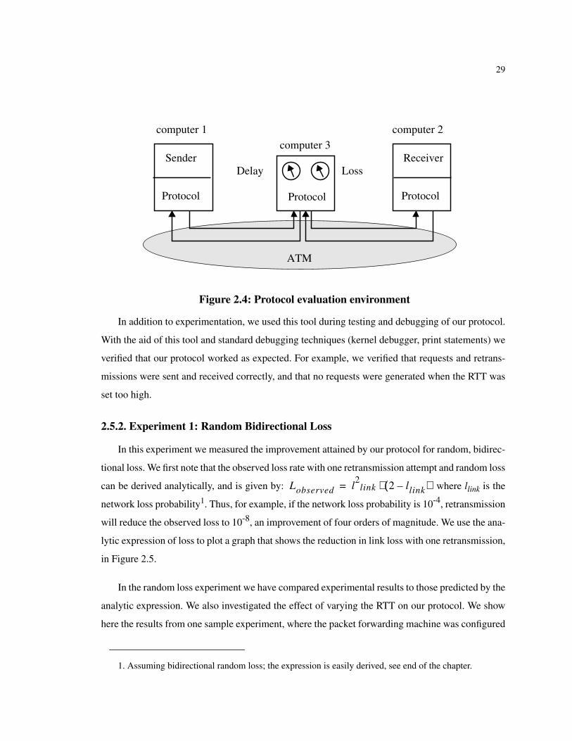
packets to the receiver. The tool is used in the configuration shown in Figure 2.4 to emulate a variety
network delays and loss models. The tool allows us to apply the same loss model in both the forward
and the reverse direction, which is a pessimistic assumption since it assumes both directions are
equally congested. This has a negative impact on performance by dropping too many retransmission
requests. The tool is quite flexible; it is driven by application level system calls that set and modify
its behavior at any time during the experiment.
29
In addition to experimentation, we used this tool during testing and debugging of our protocol.
With the aid of this tool and standard debugging techniques (kernel debugger, print statements) we
verified that our protocol worked as expected. For example, we verified that requests and retrans-
missions were sent and received correctly, and that no requests were generated when the RTT was
set too high.
2.5.2. Experiment 1: Random Bidirectional Loss
In this experiment we measured the improvement attained by our protocol for random, bidirec-
tional loss. We first note that the observed loss rate with one retransmission attempt and random loss
can be derived analytically, and is given by: where llink is the
network loss probability1. Thus, for example, if the network loss probability is 10-4, retransmission
will reduce the observed loss to 10-8, an improvement of four orders of magnitude. We use the ana-
lytic expression of loss to plot a graph that shows the reduction in link loss with one retransmission,
in Figure 2.5.
In the random loss experiment we have compared experimental results to those predicted by the
analytic expression. We also investigated the effect of varying the RTT on our protocol. We show
here the results from one sample experiment, where the packet forwarding machine was configured
Figure 2.4: Protocol evaluation environment
1. Assuming bidirectional random loss; the expression is easily derived, see end of the chapter.
Sender
Protocol Protocol
Receiver
Protocol
computer 1computer 3
computer 2
Delay Loss
ATM
Lobserved l2
link 2 llink–( )⋅=

30
to randomly drop packets with probability 0.1. This probability was set artificially high for testing
purposes. Then 10,000 packets were sent and the observed loss was recorded. The results are shown
in Figure 2.6. The graph shows that our protocol maintained an error rate of about 0.019, which is
what is predicted by the analytical model, for RTTs less than the playout delay. As the RTT
increases the time to recover is reduced, and thus the observed loss quickly climbs towards the link
loss.
2.5.3. Experiment 2: Bidirectional Bursty Loss
The previous experiment tested our protocol with simple random loss which resulted mostly in
single-packet loss. In this experiment tested our protocol with bursty loss, where a larger sequence
of packets may be lost. We configured the packet forwarder to alternate between two states: a loss
state and a no-loss state. A simple model is used to emulate bursty network losses, where loss and
no-loss periods are uniformly distributed in the intervals <mean loss period plus or minus loss devi-
ation> and <mean no-loss period plus or minus no-loss deviation>. The same loss model was used
in both forward and reverse directions. The results, shown in Table 2.1, show that retransmission
significantly decreases the observed error rate; the decrease depends on the duration of the loss and
Figure 2.5: Improvement in observed loss with one retransmission
10-6 10-5 10-4
Actual Link Loss (llink)
10-12
10-10
10-8
10-6
10-4
Obs
erve
d Lo
ssObserved loss with a single retransmission
Random drop, log-log scale
Observed Loss = l2link(2-llink)

31
no loss periods, but is generally about an order of magnitude or more. Thus, this experiment shows
that even with bursty loss the gain with retransmission can be substantial.
2.5.4. Experiment 3: Bidirectional Bursty Loss with MPEG Load
In this experiment we used the loss model described by Ramamurthy and Raychaudhuri [26],
and is depicted in Figure 2.7. This model was derived by simulating several MPEG streams across
an ATM video multiplexer. The mean loss period of this model was about 4 ms, and the mean no-
loss period about 115 ms. With this loss model running on the packet forwarder, we run an applica-
tion transmitting constant-size frames at 20 frames per second. The frame size was 48 KB and
packet size was 1KB. The playout buffer was 3 frames. A total of 1000 frames were transmitted for
Figure 2.6: Experiment 1: Random, bidirectional loss
Table 2.1: Experiment 2: Bursty bidirectional loss
No-LossPeriod (ms)
No-Loss Dev(ms)
Loss Period(ms)
Loss Dev(ms)
Packet Losswith no RTX
Packet Losswith RTX
50 5 5 2 0.082 0.017100 20 10 5 0.1 0.0061100 20 5 2 0.054 0.003200 20 5 2 0.025 0
0.0 200.0 400.0 600.0 800.0
RTT (ms)
0.00
0.02
0.04
0.06
0.08
0.10
0.12
0.14O
bser
ved
Loss
Link loss: 0.1, Playout buffer: 3application sending rate 200ms

32
each measurement. The experiment has two parts: one with retransmission turned off, and the other
with retransmission turned on. Table 2.2 shows two runs of the experiment without retransmission.
The first column shows the percentage loss due to packets being transmitted during the loss period.
The second column shows how many bursts were lost during each run and the third column shows
the average size of a lost burst in terms of packets. Table 2.3 shows runs from the same experiment,
but this time with retransmissions turned on. Each run was performed with different RTT, which is
Figure 2.7: MPEG experiment setup
Table 2.2: Experiment 3: Bursty loss without retransmission
Packet Loss(%)
Number of bursts LostAverage burst loss size
(packets)
0.0253 72 170.030 95 15
Table 2.3: Experiment 3: Bursty loss with retransmission
Average RTT(ms)
Observed Packet Loss(%)
Number of bursts LostAverage burst loss size
(packets)
8 0.0019 8 1115 0.0013 4 1521 0.0024 8 1442 0.0034 11 1561 0.0075 25 1482 0.0047 17 13
ATMMux
MPEGSources
50 Mbps
Loss Model7.7 Mbps CBR
avg loss period: 4 msavg no-loss period: 115 msdata rate: 20fps, 48KB/framepacket size: 1024 bytesplayout buffer: 3 frames

33
shown on the first column. The remaining columns are the same as the previous runs. The results
show that with retransmission the observed loss is reduced by about an order of magnitude com-
pared to the loss without retransmission. The average burst loss size does not seem to change with
retransmission, even though the number of lost bursts is significantly reduced. This leads us to con-
clude that most of the lost bursts with retransmission result from lost requests. This is an indication
that multiple retransmission attempts will help in recovering more losses.
2.5.5. Experiment 4: Qualitative evaluation with raw video
In our last experiment, we used our protocol to transmit a sequence of raw video which was
displayed at the receiver to allow qualitative evaluation of the resulting stream. We set up playback
so that any missing data would appear as black pixels. The advantage of using raw video is that we
did not have to be concerned with problems with compression, like losing synchronization. We
viewed the stream with retransmission turned on and off. The result was a clear improvement with
retransmission, while there were no adverse effects in frame timing. We believe that this is a strong
hint that the protocol will improve the subjective quality of CM streams.
2.6. Future Work: Extending Protocol to Multiple Retransmissions
In the previous sections we have argued that gap-based loss detection works well with contin-
uous media streams because the continuous flow of data allows fast gap detection, without resorting
to timers. However, while the protocol we described works well for detecting lost data packets, it
does not allow us to detect lost requests and retransmissions, and can only be used to send a single
request per gap. Since our experiments have indicated that multiple retransmission attempts may be
beneficial, it is desirable to extend the protocol to multiple retransmission attempts, but without los-
ing the fast detection capabilities provided by gap detection.
To extend our protocol to multiple retransmissions, we add another field to the packet header
which we use to perform retransmission gap detection. This field carries the sequence ID number
of the last retransmission request serviced by the sender. We emphasize that the retransmission ID
sequence number is totally independent of the packet sequence number. The use of the new field is
depicted in Figure 2.8. The steps performed by the receiver and the sender are as follows:

34
Receiver:
• Upon detection of a gap in the CM stream, the receiver performs a retransmission test (i.e.,
it checks if enough time is available to recover lost data), creates a retransmission request
and assigns it a new request ID from a monotonically increasing sequence number space.
A copy of the request is saved in a retransmission request stack.
• If the stack contains other outstanding requests, a retransmission test is performed for each
one. As a safeguard, all requests for which the retransmission test succeeds may be bun-
dled with the new request and immediately sent to the sender. This is not necessary, but
since requests are short, the overhead of bundling requests is low, and such redundancy
may guard against any previously lost requests. Since requests are stored in LIFO order, if
the retransmission test fails for a request all other requests below in the stack can be safely
discarded.
• When there are outstanding requests, the receiver examines the retransmission ID field of
all incoming data packets. If the retransmission ID field is equal or higher than the next
expected retransmission ID but only some or none of the retransmitted packets were
received, the receiver performs a retransmission test and sends a request with a new ID for
the missing packets. The old request is removed from the stack.
• Periodically, the receiver traverses the request stack performing a retransmission test as
described before. Requests that pass the test are sent again. All others are discarded.
Figure 2.8: The use of RtxRq ID fields
gap
15,06,17,18,116,1 5,09,0
RtxRq, ID: 1
Packet StreamSender Receiver
Rtx(packets 6, 7, 8)

35
• When a retransmission is received, the receiver removes the corresponding request from
the stack.
Sender
• The sender keeps a local variable containing the maximum request ID serviced. Upon
reception of a request, the sender checks the request ID to ensure that this is a new request.
If not, the request is discarded.
• If the request has not been serviced, the sender sends the requested retransmissions and
updates its local state, as well as the request ID field in all subsequent data packets.
The most significant cost of this scheme is the additional field in the packet header. Other costs
include possible redundant requests that may be sent to the sender. The scheme, however, totally
eliminates duplicate and late retransmissions while allowing fast loss detection and recovery.
2.7. Conclusions
In this chapter we have presented a retransmission-based error control protocol aimed at inter-
active continuous media applications. The protocol differs from traditional protocols in that it
employs gap-detection, conditional retransmission, and playout buffering in order to serve the
requirements of CM applications. We have implemented the protocol in the kernel of NetBSD Unix,
alongside with protocols like TCP and UDP. We have evaluated the protocol with a variety of exper-
iments, which have shown that the protocol significantly reduces observed loss, often by orders of
magnitude, without violating the timing constraints of continuous media applications. We have also
described how to extend the protocol to continuously sense available time and attempt multiple
retransmissions only while there is a reasonable chance for recovery.
We believe that with our protocol we have presented strong evidence that retransmission can be
effective in reducing loss in a wide range of CM applications. This result is important because, at
the time our work was done, it was commonly believed that retransmission was unsuitable for such
applications. Our most significant contribution, the error control scheme, is not tied to a particular
protocol implementation, and thus can be incorporated in other protocols for CM applications (e.g.,
those currently using RTP [27]).
36
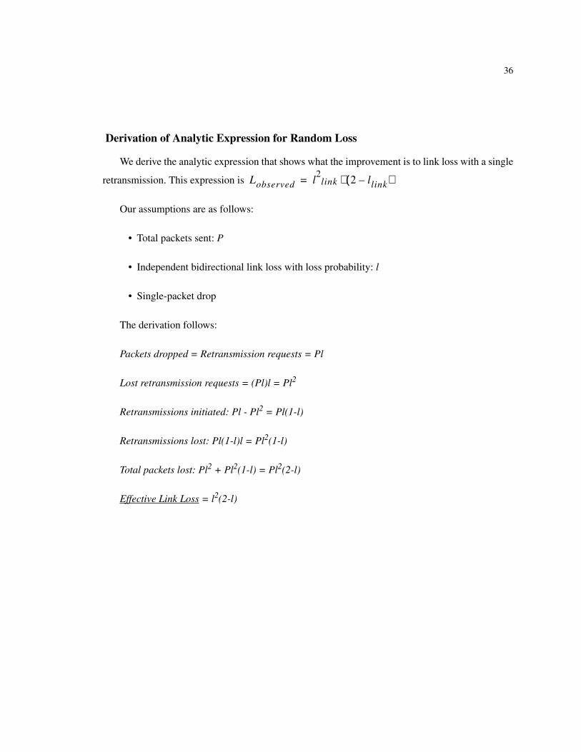
Derivation of Analytic Expression for Random Loss
We derive the analytic expression that shows what the improvement is to link loss with a single
retransmission. This expression is
Our assumptions are as follows:
• Total packets sent: P
• Independent bidirectional link loss with loss probability: l
• Single-packet drop
The derivation follows:
Packets dropped = Retransmission requests = Pl
Lost retransmission requests = (Pl)l = Pl2
Retransmissions initiated: Pl - Pl2 = Pl(1-l)
Retransmissions lost: Pl(1-l)l = Pl2(1-l)
Total packets lost: Pl2 + Pl2(1-l) = Pl2(2-l)
Effective Link Loss = l2(2-l)
Lobserved l2
link 2 llink–( )⋅=