chapter 15
TRANSCRIPT

Fire Detection, Alarm, and Suppression Systems 559
INTRODUCTIONThere are a number of reasons for installing fire
detection and alarm systems. Each system is de-signed to fulfill specific needs. The following arerecognized functions:
• To notify occupants of a facility to takenecessary evasive action to escape the dan-gers of a hostile fire
• To summon organized assistance to initiateor to assist in fire control activities
• To initiate automatic fire control and sup-pression systems and to sound an alarm
• To supervise fire control and suppressionsystems to assure that operational status ismaintained
• To initiate a wide variety of auxiliary func-tions involving environmental, utility, andprocess controls
Fire detection and alarm systems may incorpo-rate one or all of these features. Such systems mayinclude components that operate mechanically,hydraulically, pneumatically, or electrically, butmost state-of-the-art systems operate electroni-cally.
Despite advances in other forms of fixed fireprotection suppression systems, automatic sprin-kler systems remain the most reliable form forcommercial, industrial, institutional, residential,and other occupancies. It is proven that fires con-trolled by sprinklers result in less business inter-ruption and water damage than those that have tobe extinguished by traditional fire departmentmethods. In fact, data compiled by Factory MutualResearch Corporation indicates that about 70 per-cent of all fires are controlled by the activation offive or fewer sprinklers.
Chapter 15
Fire Detection, Alarm, andSuppression Systems
The first part of this chapter discusses the mostcommon types of fire detection and alarm systemsand devices in use in North America. The secondpart of the chapter describes automatic sprinklersystems. Factors to consider during fires at pro-tected properties are also given.
TYPES OF ALARM SYSTEMS[NFPA 1001: 4-5.1; 4-5.1(a); 4-5.1(b)]
The most basic alarm system is designed toonly be initiated manually. This is a local warningsystem similar to the type installed in schools ortheaters, and the signal alerts occupants of theneed to evacuate the premises. While alarm stan-dards have traditionally called this type a localsystem, contemporary terminology uses protectedpremises fire alarm systems (Figure 15.1).
A wide variety of optional features are avail-able to expand the capabilities of an alarm system.
Figure 15.1 The two components of a local alarm system.
560 ESSENTIALS
Automatic fire detection devices may be added,allowing the system to sense the presence of a fireand to initiate a signal. These are discussed in thefollowing sections.
Four basic types of automatic alarm-initiatingdevices are designed to detect heat, smoke, firegases, and flame. The following sections describethe most common types of devices in use.
Heat DetectorsSeveral different types of heat detection de-
vices, such as fixed-temperature devices and rate-of-rise detectors, are discussed in the followingsections.
FIXED-TEMPERATURE HEAT DETECTORS
Systems using fixed-temperature heat-detec-tion devices are among the oldest types of firedetection systems in use. They are relatively inex-pensive compared to other types of systems, andthey are least prone to false activations. But heatdetectors are also the slowest to activate of all thevarious types of alarm-initiating devices.
Because heat rises, heat detectors must beplaced in high portions of a room, usually on theceiling (Figure 15.2). Detectors should have anactivation temperature rating slightly above thehighest ceiling temperatures normally expected inthat space.
The various types of fixed-temperature devicesdiscussed detect heat by one or more of threeprimary principles of physics:
• Expansion of heated material
• Melting of heated material
• Changes in resistance of heated material
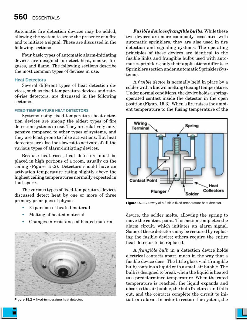
Fusible devices/frangible bulbs. While thesetwo devices are more commonly associated withautomatic sprinklers, they are also used in firedetection and signaling systems. The operatingprinciples of these devices are identical to thefusible links and frangible bulbs used with auto-matic sprinklers; only their applications differ (seeSprinklers section under Automatic Sprinkler Sys-tems).
A fusible device is normally held in place by asolder with a known melting (fusing) temperature.Under normal conditions, the device holds a spring-operated contact inside the detector in the openposition (Figure 15.3). When a fire raises the ambi-ent temperature to the fusing temperature of the
Figure 15.3 Cutaway of a fusible fixed-temperature heat detector.
device, the solder melts, allowing the spring tomove the contact point. This action completes thealarm circuit, which initiates an alarm signal.Some of these detectors may be restored by replac-ing the fusible device; others require the entireheat detector to be replaced.
A frangible bulb in a detection device holdselectrical contacts apart, much in the way that afusible device does. The little glass vial (frangiblebulb) contains a liquid with a small air bubble. Thebulb is designed to break when the liquid is heatedto a predetermined temperature. When the ratedtemperature is reached, the liquid expands andabsorbs the air bubble, the bulb fractures and fallsout, and the contacts complete the circuit to ini-tiate an alarm. In order to restore the system, theFigure 15.2 A fixed-temperature heat detector.

Fire Detection, Alarm, and Suppression Systems 561
entire detector must be replaced. While detectorsof this type are still in service, their manufacturehas been discontinued.
Continuous line detector. Most of the detec-tors described in this chapter are of the spot type;that is, they are designed to detect heat only in arelatively small area surrounding the specific spotwhere they are located. However, continuous linedetection devices can detect heat over a linear areaparallel to the detector.
One such device consists of a cable with aconductive metal inner core sheathed with stain-less steel tubing (Figure 15.4). The inner core andthe sheath are separated by an electrically insulat-ing semiconductor material that keeps them fromtouching but allows a small amount of current toflow between the two. This insulation loses some ofits electrical resistance capabilities at a predeter-mined temperature anywhere along the line. Whenthis condition happens, the current flow betweenthe two components increases, initiating an alarmsignal through the system control unit. This type ofdetection device restores itself when the level ofheat is reduced.
Another type uses two insulated wires withinan outer covering. When the rated temperature isreached, the insulation melts and allows the two
Figure 15.4 Tubing-type continuous line heat detector.
wires to touch. This action completes the circuitand initiates an alarm signal through the systemcontrol unit (Figure 15.5). To restore this type ofline detector, the fused portion of the wires must becut out and replaced with new wire.
Bimetallic detector. One type of bimetallicdetector uses two metals that have different ther-mal expansion characteristics. Thin strips of themetals are bonded together, and one or both endsof the strips are attached to the alarm circuit.When heated, one metal expands faster than the
Figure 15.5 Wire-type continuous line heat detector.

562 ESSENTIALS
other, causing the strip to arch or bend. Thedeflection of the strip either makes or breaks con-tact in the alarm circuit, initiating an alarm signalthrough the system control unit. Another type ofbimetallic detector utilizes a snap disk andmicroswitch (Figure 15.6). Most bimetallic detec-tors will reset automatically when cooled. After afire, however, they do need to be checked to ensurethat they were not damaged.
Figure 15.6 Cutaway of a bimetallic detector.
RATE-OF-RISE HEAT DETECTORSA rate-of-rise heat detector operates on the prin-
ciple that the temperature in a room will increasefaster from fire than from atmospheric tempera-ture. Typically, rate-of-rise heat detectors are de-signed to initiate a signal when the rise in tempera-ture exceeds 12 to 15°F (7°C to 8°C) per minute.Because the alarm is initiated by a sudden rise intemperature, regardless of the initial tempera-ture, an alarm can be initiated at a temperature farbelow that required for a fixed-temperature device.
Most rate-of-rise heat detectors are reliableand not subject to false activations. However, if notproperly installed, they can be activated undernonfire conditions. For example, a rate-of-rise de-tector is installed just inside an exterior door in anair-conditioned building. If the door is opened on a
hot day, the influx of heated air can rapidly in-crease the temperature around the detector andcause it to actuate. Relocating the detector fartherfrom the doorway should alleviate the problem.
There are several different types of rate-of-riseheat detectors in use; all automatically reset ifundamaged. The different types are discussed inmore detail in the following paragraphs.
Pneumatic rate-of-rise spot detector. Apneumatic spot detector is the most common typeof rate-of-rise detector in use (Figure 15.7). Itconsists of a small dome-shaped air chamber witha flexible metal diaphragm in the base. A smallmetering hole al-lows air to enterand exit the cham-ber during the nor-mal rise and fall ofatmospheric tem-perature and baro-metric pressure. Inthe heat of a fire,however, the airwithin the cham-ber expands fasterthan it can escapethrough the meter-ing hole. This expansion causes the pressure withinthe chamber to increase, forcing the metal dia-phragm against contact points in the alarm circuit.An alarm signal to the system control unit results.This type of detector is most often combined in oneunit that also has fixed-temperature capability.
Pneumatic rate-of-rise line detector. Thespot detector monitors a small area surroundingits location; however, a line detector can monitorlarge areas. A line detector consists of a system oftubing arranged over a wide area of coverage (Fig-ure 15.8). The space inside the tubing acts as theair chamber described in the preceding paragraphon spot detectors. The line detector also contains adiaphragm and is vented. When any portion of thetubing is subjected to a rapid increase in tempera-ture, the detector functions in the same manner asthe spot detector. The tubing in this system mustbe limited to about 1,000 feet (300 m) in length. Thetubing should be arranged in rows that are notmore than 30 feet (9 m) apart and 15 feet (5 m) fromwalls.
Figure 15.7 A rate-of-rise spot heatdetector.

Fire Detection, Alarm, and Suppression Systems 563
Rate-compensated detector. This detector isdesigned for use in areas that are normally subjectto regular temperature changes that are slowerthan those under fire conditions. The detector con-sists of an outer metallic sleeve that encases twobowed struts that have a slower expansion ratethan the sleeve (Figure 15.9). The bowed strutshave electrical contacts on them. In the normalposition, these contacts do not come together. Whenthe detector is heated rapidly, the outer sleeveexpands in length. This expansion reduces thetension on the inner strips and allows the contactsto come together, thus initiating an alarm signalthrough the system control unit.
Figure 15.8 A pneumatic rate-of-rise heat detector.
Figure 15.9 Cutaway of a rate-compensated heat detector.
If the rate of temperature rise is fairly slow,such as 5°F (2°C to 3°C) per minute, the sleeveexpands slowly enough to maintain tension on theinner strips. This tension prevents unnecessarysystem activations. However, regardless of therate of temperature increase, when the surround-ing temperature reaches a predetermined point,an alarm signal will be initiated.
Thermoelectric detector. This rate-of-risedetector operates on the principle that when twowires of dissimilar metals are twisted together and
heated at one end, an elec-trical current is generatedat the other end (Figure15.10). The rate at whichthe wires are heated deter-mines the amount of cur-rent that is generated.These detectors are de-signed to “bleed off” or dis-sipate small amounts ofcurrent. This reduces thechance of a small tempera-ture change activating an
alarm unnecessarily. Rapid changes in tempera-ture result in larger amounts of current flowingand activation of the alarm system.
Smoke DetectorsBecause a smoke detector can respond to smoke
produced very early in a fire’s development anddoes not have to wait for heat to be generated, it caninitiate an alarm of fire much more quickly than aheat detector. For this reason, the smoke detectoris the preferred detector in many types of occupan-cies. The two basic types, photoelectric and ioniza-tion, are described in the following sections, alongwith a discussion of power sources for smoke detec-tors.
PHOTOELECTRIC SMOKE DETECTORA photoelectric detector, sometimes called a
visible products-of-combustion detector, uses a pho-toelectric cell coupled with a specific light source.The photoelectric cell functions in two ways todetect smoke: beam application and refractoryapplication.
The beam application type uses a beam of lightfocused across the area being monitored and ontoa photoelectric cell. The cell constantly convertsthe beam into current, which keeps a switch open.
Figure 15.10 A typical thermo-electric heat detector.
564 ESSENTIALS
When smoke obscures the path of the light beam,the required amount of current is no longer pro-duced, the switch closes, and an alarm signal isinitiated (Figure 15.11).
The refractory photocell uses a light beam thatpasses through a small chamber at a point awayfrom the light source. Normally, the light does notstrike the photocell, and no current is produced.This allows the switch to remain open. When smokeenters the chamber, it causes the light beam to berefracted (scattered) in all directions. A portion ofthe scattered light strikes the photocell, causingcurrent to flow. This current causes the switch toclose and initiates the alarm signal (Figure 15.12).
Figure 15.11 Principle of a beam-application photoelectric smokedetector.
Figure 15.12 Principle of a refractory photoelectric smoke detector.
A photoelectric detector works satisfactorily onall types of fires and automatically resets when theatmosphere is clear. Photoelectric detectors aregenerally more sensitive to smoldering fires thanare ionization detectors.
IONIZATION SMOKE DETECTOR
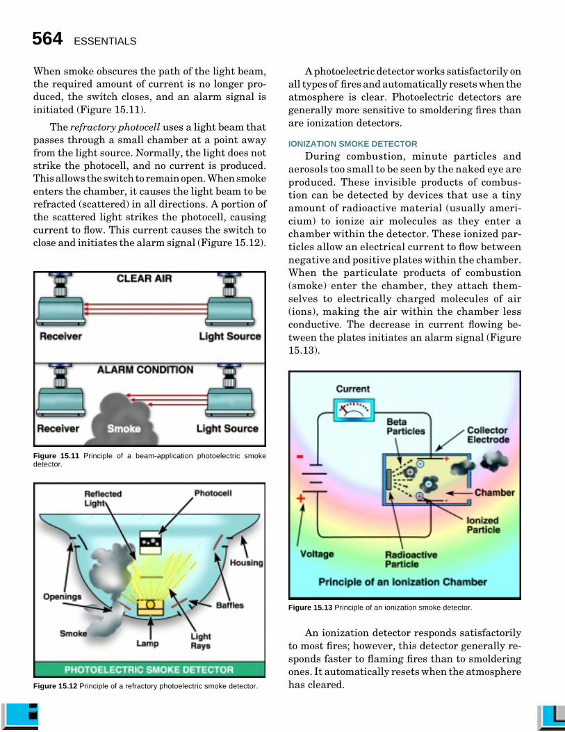
During combustion, minute particles andaerosols too small to be seen by the naked eye areproduced. These invisible products of combus-tion can be detected by devices that use a tinyamount of radioactive material (usually ameri-cium) to ionize air molecules as they enter achamber within the detector. These ionized par-ticles allow an electrical current to flow betweennegative and positive plates within the chamber.When the particulate products of combustion(smoke) enter the chamber, they attach them-selves to electrically charged molecules of air(ions), making the air within the chamber lessconductive. The decrease in current flowing be-tween the plates initiates an alarm signal (Figure15.13).
Figure 15.13 Principle of an ionization smoke detector.
An ionization detector responds satisfactorilyto most fires; however, this detector generally re-sponds faster to flaming fires than to smolderingones. It automatically resets when the atmospherehas cleared.

Fire Detection, Alarm, and Suppression Systems 565
POWER SOURCES
Either batteries or household current can powerresidential smoke detectors. Battery-operated de-tectors offer the advantage of easy installation — ascrewdriver and a few minutes are all that areneeded (Figure 15.14). Battery models are alsoindependent of housepower circuits andoperate during powerfailures.
F i r e fi g h t e r sshould be aware ofany state/province orlocal laws that dealwith smoke detec-tors. Such legislation,in addition to spell-ing out minimum in-stallation require-ments for given occu-pancies (includinghomes), may desig-nate the power source to be used. Laws requiringhard-wired units were precipitated by statisticsshowing a growing lack of maintenance in battery-operated detectors (worn-out batteries not beingreplaced). Consequently, many codes requiringdetectors in newly constructed homes specify 110-volt, hard-wired units. The detector powered byhousehold current is usually the most reliablemechanism. However, in some rural areas andareas with high thunderstorm occurrence, powerfailures may be more frequent, and battery-oper-ated units may be more appropriate.
It is critical that the specific battery type rec-ommended by the detector’s manufacturer be usedfor replacement. The batteries should be changedat least twice a year or more often if necessary. Oneway firefighters can get citizens to remember whento change smoke-detector batteries is by suggest-ing the change be made in the spring and fall at thesame time clocks are reset for daylight savings orreturned to standard time.
Flame DetectorsThere are three basic types of flame detectors
(sometimes called light detectors).
• Those that detect light in the ultravioletwave spectrum (UV detectors) (Figure 15.15)
Figure 15.14 The most common typeof residential smoke detector is batteryoperated.
• Those that detect light in the infrared wavespectrum (IR detectors) (Figure 15.16)
• Those that detect both types of light
While these types of detectors are among themost sensitive in detecting fires, they are alsoeasily activated by nonfire conditions such as weld-ing, sunlight, and other sources of bright light.They should only be located in areas where theseconditions are unlikely. They must be positioned sothat they have an unobstructed view of the pro-tected area. If their line of sight is blocked, they willnot activate.
Figure 15.15 A UV detector. Courtesy of Detector Electronics Corp.
Figure 15.16 An IR detector. Courtesy of Detector Electronics Corp.
Because some single-band IR detectors are sen-sitive to sunlight, they are usually installed in fullyenclosed areas. To reduce the likelihood of falsealarms, most IR detectors are designed to requirethe flickering motion of a flame to initiate an alarm.
Ultraviolet detectors are virtually insensitiveto sunlight, so they can be used in areas not

566 ESSENTIALS
suitable for IR detectors. However, they are notsuitable for areas where arc welding is done orwhere intense mercury-vapor lamps are used.
Fire-Gas DetectorsWhen a fire burns in a confined space, it changes
the makeup of the atmosphere within the space.Depending on the fuel, some of the gases releasedby a fire may include the following:
• Water vapor (H2O)
• Carbon dioxide (CO2)
• Carbon monoxide (CO)
• Hydrogen chloride (HCl)
• Hydrogen cyanide (HCN)
• Hydrogen fluoride (HF)
• Hydrogen sulfide (H2S)
Only water vapor, carbon dioxide, and carbonmonoxide are released from all fires. Other gasesreleased vary with the specific chemical makeup ofthe fuel. Therefore, it is only practical to monitorthe levels of carbon dioxide and carbon monoxidefor general fire-detection purposes (Figure 15.17).This type of detector will initiate an alarm signalsomewhat faster than a heat detector but not asquickly as a smoke detector.
Of more importance than the speed of responseis the fact that a fire-gas detector can be morediscriminating than other types of detectors. A fire-gas detector can be designed to be sensitive only tothe gases produced by specific types of hostile firesand to ignore those produced by friendly fires. Thisdetector uses either semiconductors or catalyticelements to sense the gas and trigger the alarm.Compared to the number of other types of detec-tors, few fire-gas detectors are in use.
Figure 15.17 A fire-gas detector.
Combination DetectorsDepending on the design of the system, vari-
ous combinations of the previously describedmeans of detection may be used in a single device.These combinations include fixed temperature/rate-of-rise heat detectors, combination heat/smoke detectors, and combination smoke/fire-gas detectors (Figure 15.18). The different combi-nations make these detectors more versatile andmore responsive to fire conditions.
Figure 15.18 A combination heat/smoke detector.
Indicating DevicesA large assortment of audible and visible alarm-
indicating devices have also been developed. Someare loud to attract attention in high-noise areas;some generate an electronic tone that is audible inalmost any type of environment. Some systemsemploy bells, horns, or chimes; others use speakersthat broadcast prerecorded evacuation instruc-tions (Figure 15.19).
To accommodate special circumstances or popu-lations, such as people who must wear personalnoise-attenuation devices because of very highnoise levels in their work areas, visual alarm indi-cators that employ an extremely high intensityclear strobe may be used. These indicators may beused singularly or in combination with other alarmdevices (Figure 15.20). Appropriate strobe devicesmay also be used to meet the requirements of theAmericans with Disabilities Act (ADA) in areaswhere there may be people with hearing impair-ments.

Fire Detection, Alarm, and Suppression Systems 567
Figure 15.19 Typical evacuation alarm devices.
Figure 15.20 A strobe evacuation alarm device.
Automatic Alarm SystemsUnder some circumstances, insurance carriers
may require occupancies to have a system that willtransmit a signal to an off-site location for thepurpose of summoning organized assistance infighting a fire. This signal produces an automaticresponse upon activation of the local alarm at theprotected premises. Various brands of alarm sys-tems do this signaling with dedicated wire pairs,leased telephone lines, fiber-optic cable, or wire-less communication links.
AUXILIARY SYSTEM
There are three basic types of auxiliary sys-tems: the local energy system, the shunt system,and the parallel telephone system.
Local energy system. A local energy system isused only in those communities that are served bya municipal fire-alarm-box system. A local energysystem is an auxiliary alarm system within anoccupancy that is attached directly to a hard-wiredor radio-type municipal fire alarm box (Figure15.21). When an alarm activates in the protectedoccupancy, it trips the alarm box to which it isattached and transmits an alarm to the fire alarmcenter. An alarm can be initiated by manual pullstations, automatic fire detection devices, or waterflow devices. Each community has its own require-ments for local energy systems, and some do notallow them at all.
Figure 15.21 A munici-pal master box.

568 ESSENTIALS
Shunt system. A shunt system is one in whichthe municipal alarm circuit extends (is “shunted”)into the protected property. When an alarm isinitiated on the premises, whether manually orautomatically, the alarm is instantly transmittedto the alarm center over the municipal system.
Parallel telephone system. A parallel tele-phone system does not interconnect with a munici-pal alarm circuit. It transmits an alarm from theprotected property directly to the alarm centerover a municipally controlled telephone circuitthat serves no other purpose.
REMOTE STATION SYSTEM
A remote station system is similar to an auxil-iary system but is connected to the fire departmenttelecommunication center directly or through ananswering service by some means other than themunicipal fire-alarm-box system (Figure 15.22).This connection can be done by leased telephoneline or, where permitted, by a radio signal on adedicated frequency. A remote station is commonin localities that are not served by central stationsystems described later.
A remote station system may transmit either acoded or a noncoded signal. A noncoded system isonly allowable where a single occupancy is pro-tected by the system. Up to five facilities may beprotected by one coded system. These five facilitiesusually have a common connection to the remotestation. A remote station system must have the
Figure 15.22 A remote system connects directly to the fire departmenttelecommunication center.
ability to transmit a trouble signal to the firealarm center when the system becomes impaired(Figure 15.23). This type of system may not havelocal alarm capabilities if evacuation is not thedesired action in the event of a fire.
Depending on local policy, the fire depart-ment may allow another entity, such as thepolice department, to monitor the remote station(Figure 15.24). This situation is particularlycommon in communities that have volunteer firedepartments whose stations are not constantlystaffed. In these cases, it is important that policetelecommunicators are appropriately trained inthe actions that need to be taken immediatelyupon receiving a fire-alarm signal.
Figure 15.23 A remote system must be capable of transmitting a troublesignal if the system is impaired.
Figure 15.24 Police telecommunications personnel monitor many remotestations.

Fire Detection, Alarm, and Suppression Systems 569
PROPRIETARY SYSTEM
A proprietary system is used to protect largecommercial and industrial buildings, high rises,and groups of commonly owned buildings in asingle location such as a college campus or indus-trial complex (Figure 15.25). Each building or areahas its own system that is wired into a commonreceiving point somewhere on the facility. Thereceiving point must be in a separate structure orin a part of the structure that is remote from anyhazardous operations. The receiving station is con-stantly staffed by representatives of the occupantwho are trained in system operation and the ac-tions to take when an alarm is received (Figure15.26). The operator should be able to summon thefire department either through the system or bytelephone.
Figure 15.25 Components of a proprietary system.
Figure 15.26 Trained personnel staff the receiving station.
Modern proprietary systems can be very com-plex with a wide range of capabilities. Some ofthese capabilities include the following:
• Transmitting coded-alarm and trouble sig-nals
• Monitoring building-utility controls
• Monitoring elevator status
• Monitoring fire and smoke dampers
• Performing security functions
CENTRAL STATION SYSTEM
A central station system is very similar to aproprietary system. The primary difference is thatinstead of having the alarm-receiving point moni-tored by the occupant’s representative on the pro-tected premises, the receiving point is at an off-site, contracted service point called a central sta-tion (Figure 15.27). Typically, the central station isan alarm company that contracts with individualcustomers. When an alarm is initiated at a con-tracting occupancy, central station employees takethat information and initiate an appropriate emer-gency response. This response usually includescalling the fire department and representatives ofthe protected occupancy. The alarm system at the
Figure 15.27 Components of a central station system.

570 ESSENTIALS
protected property and the central station are mostcommonly connected by supervised telephone lines.All central station systems should comply with therequirements of NFPA 72, National Fire AlarmCode.
Supervising Fire Alarm SystemsUnlike ordinary electrical distribution systems
that provide power, fire alarm systems are de-signed to be self-supervising. This means thatanytime the system is not operating normally, adistinct trouble signal is generated to attract at-tention to the system problem (Figure 15.28). Thismay happen when the system switches to batterypower because of a utility power outage or whenthere is a break in a detector or notification circuit.
Most oldersystems operatedwith looped, su-pervised circuitsin which a tinycurrent was con-stantly flowing. Adetector wouldinitiate a signalby closing contactpoints to create ashort circuit. Inthe same way, if abreak occurred inone of the detec-
tor circuits, a trouble signal would be initiatedbecause the supervisory current would be inter-rupted.
Many newer systems incorporate some of thelatest technological developments of the telecom-munication and computer industries. Some of thesesystems have built-in microprocessors programmedto initiate an internal diagnostic test at specifiedintervals. The results are recorded on a printer ordisplayed on a computer screen (Figure 15.29). Thesame printer or screen is also used to present alarminformation.
The sounds of the alarm and trouble signalsmay be different with each brand of system in use.Firefighters should familiarize themselves withboth signals from each brand of system in theirarea.
Figure 15.28 An alarm panel with a “trouble”light.
Figure 15.29 Modern systems provide a printout to indicate trouble withthe system.
Many fixed fire suppression systems depend ona signal from a manual pull station or from anautomatic fire detection device to trigger the sup-pression system (Figure 15.30). The control panelmust be specifically listed by a testing laboratoryfor this purpose, and all control circuits must besupervised.
Depending on the ap-plication, a number ofspecific features may beincorporated. NFPA 12,Standard on Carbon Diox-ide Extinguishing Systems,requires a predischargealarm. Some systems maybe programmed to providean extended discharge pe-riod to ensure that a fire-suppressing concentrationof CO2 is achieved. To pre-vent people from entering the oxygen-deficientenvironment, automatic door-locking devices maybe provided. Older CO2 systems may be equippedwith a pneumatic means of activation. These sys-tems represent another generation of technologythat continues to provide reliable protection aslong as the systems are tested regularly and main-tained in accordance with the manufacturers’ in-structions.
Fire alarm and supervisory systems may beinstalled to complement either wet-pipe or dry-pipe sprinkler systems (see Applications of Sprin-
Figure 15.30 A manual stationthat initiates an alarm andactuates the suppressionsystem.

Fire Detection, Alarm, and Suppression Systems 571
kler Systems section). Devices capable of sensing asudden increase or decrease in pressure can detectmovement or flow of water; others are actuated bythe actual movement of water within a pipe (Figure15.31). This movement would indicate that eithera sprinkler had opened in response to a fire or thatwater was leaking from a broken pipe. To minimizefalse alarms but maintain appropriate sensitivity,the detection device is set to respond to flow equalto that of a single sprinkler.
Figure 15.31 A water flow alarm device.
Auxiliary ServicesWhile the primary objective of a fire detection
and alarm system is to prevent loss of life and toconserve property in the event of a fire, technologi-cal improvements have enhanced the capabilitiesof contemporary emergency signals systems. Sys-tems that integrate process and environmentalcontrols, security, and personnel-access controlsare now common. The following are some of theother auxiliary services available:
• Shutting down or altering airflow in heat-ing, ventilating, and air-conditioning(HVAC) systems for smoke control
• Closing smoke or fire-rated doors anddampers
• Facilitating evacuation by increasing airpressure in stairwells to exclude smoke
• Overriding elevator controls
• Monitoring operation of burner manage-ment systems Figure 15.32 A sprinkler in operation.
• Monitoring refrigeration systems and cold-storage areas
• Controlling personnel access to hazardousprocess or storage areas
• Detecting combustible or toxic gases
AUTOMATIC SPRINKLER SYSTEMS[NFPA 1001: 3-3.13(a); 3-3.13(b);4-5.1; 4-5.1(a); 4-5.1(b)]
Automatic sprinkler protection consists of aseries of sprinklers (sometimes called sprinklerheads) arranged so that the system will automati-cally distribute sufficient quantities of water di-rectly to a fire to either extinguish it or hold it incheck until firefighters arrive (Figure 15.32). Wa-ter is supplied to the sprinklers through a systemof piping. The sprinklers can either extend fromexposed pipes or protrude through the ceiling orwalls from hidden pipes.
There are two general types of sprinkler cover-age: complete sprinkler coverage and partial sprin-kler coverage. A complete sprinkler system protectsthe entire building. A partial sprinkler systemprotects only certain areas such as high-hazardareas, exit routes, or places designated by code orby the authority having jurisdiction.
Standards such as NFPA 13, Standard for theInstallation of Sprinkler Systems, or NFPA 13D,Standard for the Installation of Sprinkler Systemsin One- and Two-Family Dwellings and Manufac-tured Homes, are the primary guides used forestablishing sprinkler protection in occupancies.These standards have requirements on the spacingof sprinklers in a building, the size of pipe to be

572 ESSENTIALS
used, the proper method of hanging the pipe, andall other details concerning the installation of asprinkler system. These standards specify the mini-mum design area that should be used to calculatethe system. This area is the maximum number ofsprinklers that might be expected to activate (Fig-ure 15.33). This is done because most public watersupply systems could not be expected to adequatelysupply 500 or 1,000 operating sprinklers. Thus, thedesign of the system is based upon the assumptionthat only a portion of the sprinklers will operateduring a fire.
Figure 15.33 Sprinkler systems are designed under the assumption thatonly a portion of the total number of sprinklers will actually operate duringa fire.
The automatic sprinkler and all componentparts of the system should be listed by a nationallyrecognized testing laboratory such as Underwrit-ers Laboratories Inc. or Factory Mutual. Auto-matic sprinkler systems are now recognized as themost reliable of all fire protection devices, and it isessential for the firefighter to understand the basicsystem and the operation of pipes and valves. Thevarious applications of sprinkler systems shouldalso be known by firefighters along with sprinklersystem effects on life safety.
In general, reports reveal that only in rareinstances do automatic sprinkler systems fail to
operate. When failures are reported, the reason israrely because of failure of the actual sprinklers. Asprinkler system may not perform properly be-cause of the following:
• Partially or completely closed main watercontrol valve
• Interruption to the municipal water supply
• Damaged or painted-over sprinklers
• Frozen or broken pipes
• Excess debris or sediment in the pipes
• Failure of a secondary water supply
• Tampering and vandalism
Sprinkler System Effects on Life SafetyThe life safety of building occupants is en-
hanced by the presence of a sprinkler system be-cause it discharges water directly on a fire while itis relatively small. Because the fire is extinguishedor controlled in the early growth stage, combustionproducts are limited. Sprinklers are also effectivein the following situations:
• Preventing fire spread upwards in multiplestory buildings
• Protecting the lives of occupants in otherparts of the building
There are also times, however, when sprinklersalone are not as effective, such as in the followingsituations:
• Fires are too small to activate the sprinklersystem.
• Smoke generation reaches occupants be-fore the sprinkler system activates.
• Sleeping, intoxicated, or handicapped per-sons occupy the fire building.
Sprinkler System FundamentalsThe principal parts of an automatic sprinkler
system are illustrated in Figure 15.34. The systemstarts with a water main and continues into thecontrol valve. The riser is the vertical piping towhich the sprinkler valve, one-way check valve,fire department connection (FDC), alarm valve,main drain, and other components are attached.The feed main is the pipe connecting the riser to thecross mains. The cross mains directly service anumber of branch lines on which the sprinklers areinstalled. Cross mains extend past the last branchlines and are capped to facilitate flushing. System

Fire Detection, Alarm, and Suppression Systems 573
Figure 15.34 Components of a complete sprinkler system.
piping decreases in size from the riser outward.The entire system is supported by hangers andclamps.
Along with discussions of the various types ofsprinklers, control valves, operating valves, andwater flow alarms, an explanation of how sprinklersystems are supplied with water is also given in thefollowing sections. The various applications of sprin-kler systems (dry-pipe, wet-pipe, preaction, del-uge, and residential) are also described.
SPRINKLERS
Sprinklers discharge water after the release ofa cap or plug that is activated by some heat-responsive element (Figure 15.35). This sprinklermay be thought of as a fixed-spray nozzle that isoperated individually by a thermal detector. Thereare numerous types and designs of sprinklers.
Sprinklers are commonly identified by thetemperature at which they are designed to oper-ate. Usually this temperature is identified either Figure 15.35 Components of an upright fusible-link sprinkler.

574 ESSENTIALS
by color-coding the sprinkler frame arms, byusing different colored liquid in bulb-type sprin-klers, or by stamping the temperature into thesprinkler itself (see Table 15.1).
Three of the most commonly used releasemechanisms to activate sprinklers are fusiblelinks, frangible bulbs, and chemical pellets. Allof these sprinkler mechanisms fuse or open inresponse to heat (Figures 15.36 a–c).
Fusible link. The design of a sprinkler thatuses a fusible link involves a frame that is screwedinto the sprinkler piping. Two levers press againstthe frame, and a cap over the orifice in the frame
Maximum Ceiling Temperature Temperature Rating Temperature Color Glass Bulb
°F °C °F °C Classification Code Colors
100 38 135 to 170 57 to 77 Ordinary Uncolored or Black Orange or Red
150 66 175 to 225 79 to 107 Intermediate White Yellow or Green
225 107 250 to 300 121 to 149 High Blue Blue
300 149 325 to 375 163 to 191 Extra High Red Purple
375 191 400 to 475 204 to 246 Very Extra High Green Black
475 246 500 to 575 260 to 302 Ultra High Orange Black
625 329 650 343 Ultra High Orange Black
Reprinted with permission from NFPA 13-1996, Installation of Sprinkler Systems, Copyright © 1996, National Fire Protection Association, Quincy, MA02269. This reprinted material is not the complete and official position of the National Fire Protection Association on the referenced subject, which isrepresented only by the standard in its entirety.
TABLE 15.1Temperature Ratings, Classifications, and Color Codings
Figure 15.36a A fusible-link sprinkler. Figure 15.36c A chemical-pellet sprinkler.Figure 15.36b A frangible-bulb sprinkler.
holds back the water. The fusible link holds thelevers together until the link is melted during afire, after which the water pushes the levers andcap out of the way and strikes the deflector on theend of the frame. The deflector converts the stan-dard ¹⁄₂-inch (13 mm) stream into water spray formore efficient extinguishment.
A quick-response mechanism was developedfor life safety purposes. This specially designedfusible link offers increased surface area to collectthe heat generated by a fire faster than a standardfusible-link sprinkler. This results in a fasteropening of the sprinkler and quicker extinguish-ment of the fire.

Fire Detection, Alarm, and Suppression Systems 575
Frangible bulb. Some sprinklers use a smallbulb filled with liquid and an air bubble to hold theorifice shut. Heat expands the liquid until thebubble is absorbed into the liquid. This increasesthe internal pressure until the bulb shatters at theproper temperature. The breaking temperature isregulated by the amount of liquid and the size ofthe bubble in the bulb. The liquid is color-coded todesignate the designed breaking temperature (re-fer to Table 15.1). When the bulb shatters, thevalve cap is released. The quantity of liquid in thebulb determines when it will shatter.
Chemical pellet. A pellet of solder, undercompression, within a small cylinder melts at apredetermined temperature, allowing a plunger tomove down and release the valve cap parts.
SPRINKLER POSITION
There are three basic positions for sprinklers:pendant, upright, and sidewall. They cannot beinterchanged because they are not designed toprovide the proper spray pattern and coverage inany other position. There are also special-purposesprinklers used in other applications.
Pendant. The pendant sprinkler, the mostcommon type in use, extends down from theunderside of the piping. This sprinkler sprays astream of water downward into a deflector thatbreaks the stream into a hemispherical pattern(Figure 15.37).
Figure 15.37 The pendant sprinkler isthe most common type of sprinkler inuse. Figure 15.38 An upright sprinkler. Figure 15.39 A sidewall sprinkler installed.
Upright. The upright sprinkler sits on top ofthe piping and sprays water into a solid deflectorthat breaks it into a hemispherical pattern that isredirected toward the floor. The upright standardsprinkler cannot be inverted for use in the hangingor pendant position because the spray of waterwould be directed toward the ceiling in the invertedposition (Figure 15.38).
Sidewall. The sidewall sprinkler extends fromthe side of a pipe and is used in small rooms wherethe branch line runs along a wall. It has a specialdeflector that creates a fan-shaped pattern of wa-ter (Figure 15.39).
Special-purpose. Special-purpose sprinklersare those that are used in specific applicationsbecause of their unique characteristics. There areseveral special-purpose sprinklers for special ar-eas and uses. Special-purpose sprinklers with cor-rosive-resistant coatings are designed to be in-stalled in areas with corrosive atmospheres. Otherspecial-purpose sprinklers are designed for certainspecific applications such as being recessed in theceiling to blend in with the room decor.
SPRINKLER STORAGE
A storage cabinet for housing extra sprinklersand a sprinkler wrench should be installed in thearea protected by the sprinkler system. Normally,these cabinets hold a minimum of six sprinklersand a sprinkler wrench in accordance with NFPA
576 ESSENTIALS
Figure 15.40 A sprinkler storage cabinet.
13 and 13D (Figure 15.40). Typically, the functionof changing sprinklers is performed by representa-tives of the building’s occupants who are qualifiedto perform work on sprinkler systems.
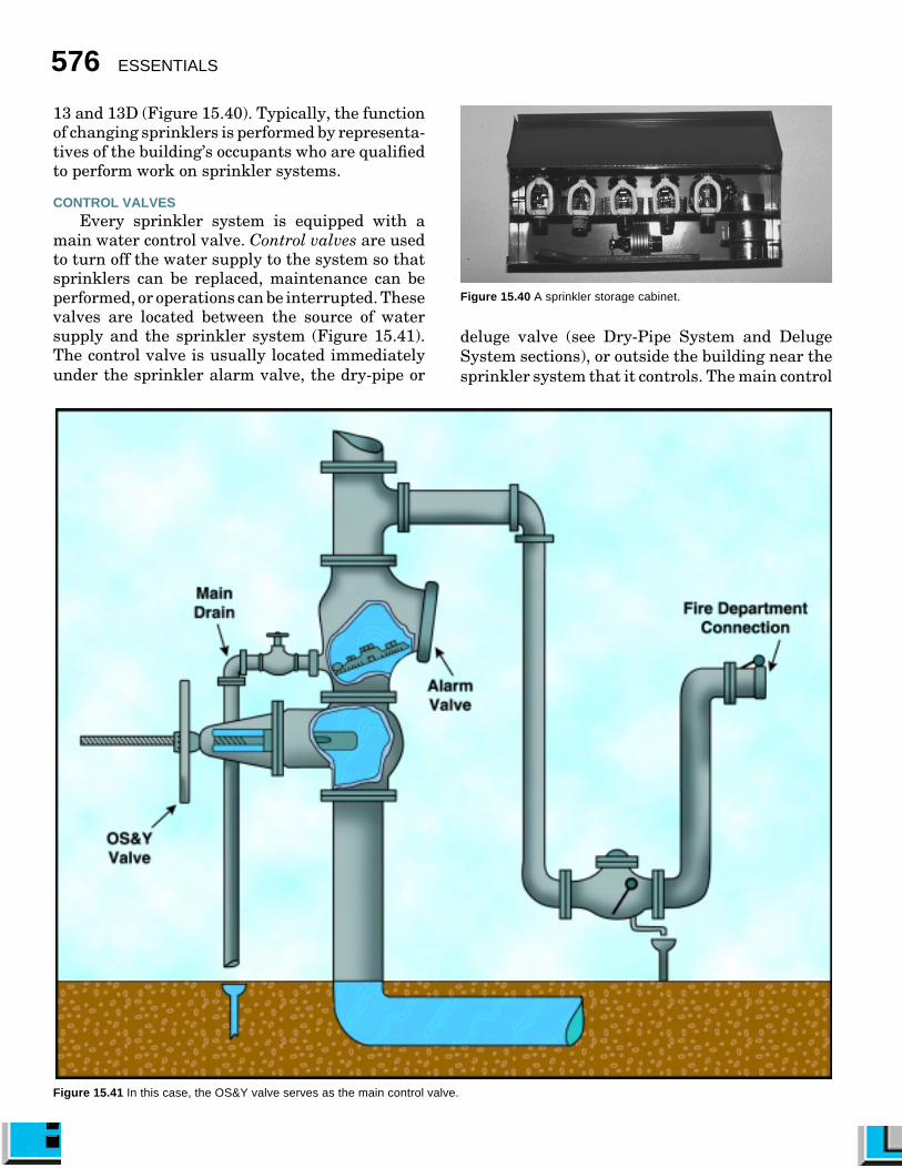
CONTROL VALVESEvery sprinkler system is equipped with a
main water control valve. Control valves are usedto turn off the water supply to the system so thatsprinklers can be replaced, maintenance can beperformed, or operations can be interrupted. Thesevalves are located between the source of watersupply and the sprinkler system (Figure 15.41).The control valve is usually located immediatelyunder the sprinkler alarm valve, the dry-pipe or
Figure 15.41 In this case, the OS&Y valve serves as the main control valve.
deluge valve (see Dry-Pipe System and DelugeSystem sections), or outside the building near thesprinkler system that it controls. The main control

Fire Detection, Alarm, and Suppression Systems 577
Figure 15.42 A small OS&Y valve.
Post indicator valve (PIV). The PIV is ahollow metal post that is attached to the valvehousing. The valve stem is inside this post; amovable target is on the stem with the wordsOPEN and SHUT at the opening. A PIV with theoperating handle in the stored and locked positionis shown in Figure 15.43.
Wall post indicator valve (WPIV). A WPIVis similar to a PIV except that it extends throughthe wall with the target and valve operating nut onthe outside of the building (Figure 15.44).
Post indicator valve assembly (PIVA). ThePIVA does not use a target with words OPEN andSHUT, but it has a sight area that is open when thevalve is open and closed when the valve is closed(Figure 15.45). Figure 15.46 A quarter-turn alarm test valve.
OPERATING VALVES
Sprinkler systems employvarious valves such as alarm testvalve, inspector’s test valve, anda main drain valve. The alarm test valve is locatedon a pipe that connects the supply side of the alarmcheck valve to the retard chamber (place thatcatches excess water from momentary water pres-sure surges) (Figure 15.46). This valve is providedto simulate the actuation of the system by allowing
Figure 15.43 A post indicator valve (PIV)showing that it is open. Note the operatinghandle locked in place.
Figure 15.44 A wall post indicator valve(WPIV).
valve should always be returned to the open posi-tion after maintenance is complete. The valvesshould be secured in the open position or at leastsupervised to make sure that they are not inad-vertently closed.
Main water control valves are indicating andmanually operated. An indicating control valve isone that shows at a glance whether it is open orclosed. There are four common types of indicatorcontrol valves used in sprinkler systems: outsidescrew and yoke (OS&Y), post indicator, wall postindicator, and post indicator valve assembly (PIVA).
Outside screw and yoke (OS&Y) valve. Thisvalve has a yoke on the outside with a threadedstem that controls the opening and closing of thegate. The threaded portion of the stem is out of theyoke when the valve is open and inside the yokewhen the valve is closed (Figure 15.42).
Figure 15.45 Apost indicatorvalve assembly(PIVA) uses abutterfly valveinstead of a gatevalve.

578 ESSENTIALS
water to flow into the retard chamber and operatethe water flow alarm devices.
An inspector’s test valve is located in a remotepart of the sprinkler system (Figure 15.47). Theinspector’s test valve is equipped with the samesize orifice as one sprinkler and is used to simulatethe activation ofone sprinkler. Thewater from theinspector’s testvalve should drainto the outside ofthe building.
Every sprin-kler system riserhas a main drainvalve. The pri-mary purpose ofthe main drain isto simply drainwater from thesystem for maintenance purposes. However, be-cause a large volume of water flows when the maindrain valve is opened, it can also be used to checkthe system water supply.
WATER FLOW ALARMS
Actuation of fire alarms by sprinkler systems isaccomplished when water flows through the sys-tem. Sprinkler water flow alarms are normally
operated either hydrauli-cally or electrically. Thehydraulic alarm is a localalarm used to alert the per-sonnel in a sprinkleredbuilding or a passerby thatwater is flowing in the sys-tem (Figure 15.48). Thistype of alarm uses the wa-ter in the system to branchoff to a water motor thatdrives a local alarm gong.The electric water flow
alarm is also employed to alert building occupants,and in addition, it can be arranged to notify the firedepartment.
Water SupplyEvery sprinkler system should have a water
supply of adequate volume, pressure, and reliabil-
ity. A minimum water supply must be able todeliver the required volume of water to the highestsprinkler in a building at a residual pressure of 15psi (100 kPa). The minimum flow depends on thehazard to be protected, its occupancy, and thebuilding contents. A connection to a public watersystem that has adequate volume, pressure, andreliability is a good source of water for automaticsprinklers. This type of connection is often the onlywater supply available.
The water supply for sprinkler systems is de-signed to supply only a fraction of the sprinklersactually installed on the system. If a large fireshould occur or if a pipe breaks, the sprinklersystem will need an outside source of water andpressure to do its job effectively. This additionalwater and pressure can be provided by a pumperthat is connected to the sprinkler fire departmentconnection (Figure 15.49). Fire department con-nections for sprinklers usually consist of a siamesewith at least two 2¹⁄₂-inch (65 mm) female connec-tions with a clapper valve (Figure 15.50) or onelarge-diameter connection that is connected to aclappered inlet.
Figure 15.49 A supply hose connected to a fire department connection(FDC).
Figure 15.50 The clapper valve is clearly visible inside this FDC.
Figure 15.47 The inspector’s test valve isequipped with the same size orifice as onesprinkler and is used to simulate theactivation of one sprinkler.
Figure 15.48 A water flowalarm (also known as a watergong) warns that water ismoving through the system.

Fire Detection, Alarm, and Suppression Systems 579
Sprinkler fire department connections shouldbe supplied with water from pumpers that havea capacity of at least 1,000 gpm (4 000 L/min) orgreater. A minimum of two 2¹⁄₂-inch (65 mm) orlarger hoses should be attached to the FDC.Whenever possible, fire department pumperssupplying attack lines should operate from hy-drants connected to mains other than the mainsupplying the sprinkler system (Figure 15.51).
After water flows through the fire depart-ment connection into the system, it passesthrough a check valve. This valve prevents waterflow from the sprinkler system back into the firedepartment connection; however, it does allowwater from the fire department connection toflow into the sprinkler system (Figure 15.52).The proper direction of water flow through acheck valve may be denoted by arrows on thevalve or by observing the appearance of the valvecasting. A ball drip valve may also be installed atthe check valve and FDC. This will keep thevalve and connection dry and operating properlyduring freezing conditions.
Figure 15.51 The correct and incorrect methods for boosting the watersupply to a sprinkler system.
A fire department’s stan-dard operating procedureshould identify the pressureat which a sprinkler systemshould be supported as well asthat needed for special circum-stances. Such a plan cannotbe established until fire de-partment personnel becomefamiliar with sprinkleredproperties under their juris-diction. A standard plan ofoperation should cover thebuildings in the department’sjurisdiction, including type ofoccupancy, type of system, andextent of the system. There-fore, a pre-incident survey is aprerequisite for a plan of op-eration (Figure 15.53). A thor-ough knowledge of the publicwater system is important, in-cluding knowing the volumeand pressure available.Figure 15.52 Note the position of the check valve in relation to the other components of the riser.

580 ESSENTIALS
Applications of Sprinkler SystemsThe following sections highlight the major ap-
plications of sprinkler systems. Firefighters shouldhave a basic understanding of the operation ofeach.
• Wet-pipe
• Dry-pipe
• Preaction
• Deluge
• Residential
WET-PIPE SYSTEM
A wet-pipe sprinkler system is used in locationsthat will not be subjected to temperatures below40°F (4°C). It is the simplest type of automatic firesprinkler system and generally requires little main-tenance. This system contains water under pres-sure at all times. It is connected to the public watersupply so that a fused sprinkler will immediatelydischarge a water spray in the area and actuate analarm. This type of system is usually equipped withan alarm check valve that is installed in the mainriser adjacent to where the feed main enters thebuilding (Figure 15.54 a). Newer wet-pipe sprin-kler systems may not have an alarm check valve.Instead they may have a backflow prevention checkvalve and an electronic flow alarm. These aresometimes referred to as straight stick systems(Figure 15.54 b). To shut down the system, turn offthe main water control valve and open the maindrain. A pressure gauge on the riser should indi-cate system pressure.
Figure 15.53 Fire department personnel conducting a survey of abuilding’s sprinkler system for a standard plan of operation.
A wet-pipe sprinkler system may be equippedwith a retarding device, commonly called a retardchamber, as part of the alarm check valve. Thischamber catches excess water that may be sentthrough the alarm valve during momentary waterpressure surges. This reduces the chance of a falsealarm activation.
DRY-PIPE SYSTEM
A dry-pipe sprinkler system is used in locationswhere the piping may be subjected to temperaturesbelow 40°F (4°C). All pipes in dry-pipe systems arepitched to help drain the water in the system backtoward the main drain. In this system, air underpressure replaces water in the sprinkler pipingabove the dry-pipe valve (device that keeps waterout of the sprinkler piping until a fire actuates asprinkler). When a sprinkler fuses, the pressurizedair escapes first, and then the dry-pipe valve auto-matically opens to permit water into the pipingsystem (Figure 15.55).
Figure 15.54a A wet-pipesystem with an alarmcheck valve.
Figure 15.54b A “straightstick” wet-pipe sprinklersystem. Note the lack of analarm check valve on theriser.

Fire Detection, Alarm, and Suppression Systems 581
Figure 15.55 Components of a dry-pipe valve.
A dry-pipe valve is designed so that a smallamount of air pressure above the dry-pipe valvewill hold back a much greater water pressure onthe water supply side of the dry-pipe valve. This isaccomplished by having a larger surface area onthe air side of the clapper valve than on the waterside of the valve. The valve is equipped with an air-pressure gauge above the clapper and a water-pressure gauge below the clapper. The required airpressure for dry-pipe systems should be 20 psi (140kPa) above the trip pressure. Under normal cir-cumstances, the air pressure gauge will read apressure that is substantially lower than the wa-ter-pressure gauge. If the gauges read the same,the system has been tripped, and water has beenallowed to enter the pipes. Figure 15.56 illustratesthe dry-pipe valve in both the standby and firepositions. Dry-pipe systems are equipped with ei-ther electric or hydraulic alarm-signaling equip-ment.
In a large dry-pipe system, several minutescould be lost while the air is being expelled from thesystem. Standards require that a quick-openingdevice be installed in systems that have a watercapacity of over 500 gallons (2 000 L). An accelera-tor is one type of quick-opening device. The basic
Figure 15.56 This illustrates the dry-pipe valve in both the standby andfire positions.
purpose of this device is to accelerate the openingof the dry-pipe valve. This allows water to beadmitted into the sprinkler system quicker, result-ing in quicker sprinkler discharge.
PREACTION SYSTEM
A preaction sprinkler system is a dry systemthat employs a deluge-type valve (see Deluge Sys-tem section), fire detection devices, and closedsprinklers. This type of system is used when it isespecially important to prevent water damage,even if pipes are broken. The system will notdischarge water into the sprinkler piping except inresponse to either smoke- or heat-detection systemactuation.
Fire detection devices operate a release locatedin the system actuation unit. This release opensthe deluge valve and permits water to enter thedistribution system so that water is ready whenthe sprinklers fuse. When water enters the system,an alarm sounds to give a warning before theopening of the sprinklers.
DELUGE SYSTEM
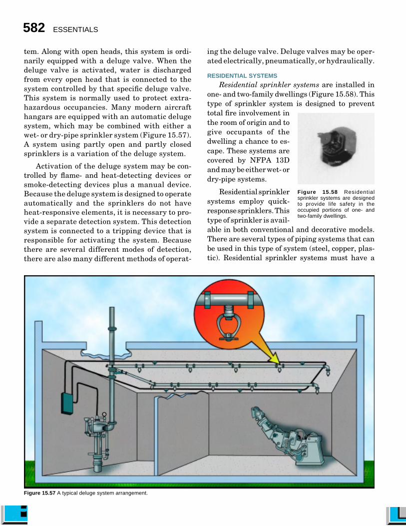
The purpose of a deluge sprinkler system is towet down the area where a fire originates bydischarging water from all open heads in the sys-
582 ESSENTIALS
tem. Along with open heads, this system is ordi-narily equipped with a deluge valve. When thedeluge valve is activated, water is dischargedfrom every open head that is connected to thesystem controlled by that specific deluge valve.This system is normally used to protect extra-hazardous occupancies. Many modern aircrafthangars are equipped with an automatic delugesystem, which may be combined with either awet- or dry-pipe sprinkler system (Figure 15.57).A system using partly open and partly closedsprinklers is a variation of the deluge system.
Activation of the deluge system may be con-trolled by flame- and heat-detecting devices orsmoke-detecting devices plus a manual device.Because the deluge system is designed to operateautomatically and the sprinklers do not haveheat-responsive elements, it is necessary to pro-vide a separate detection system. This detectionsystem is connected to a tripping device that isresponsible for activating the system. Becausethere are several different modes of detection,there are also many different methods of operat-
Figure 15.57 A typical deluge system arrangement.
ing the deluge valve. Deluge valves may be oper-ated electrically, pneumatically, or hydraulically.
RESIDENTIAL SYSTEMS
Residential sprinkler systems are installed inone- and two-family dwellings (Figure 15.58). Thistype of sprinkler system is designed to preventtotal fire involvement inthe room of origin and togive occupants of thedwelling a chance to es-cape. These systems arecovered by NFPA 13Dand may be either wet- ordry-pipe systems.
Residential sprinklersystems employ quick-response sprinklers. Thistype of sprinkler is avail-able in both conventional and decorative models.There are several types of piping systems that canbe used in this type of system (steel, copper, plas-tic). Residential sprinkler systems must have a
Figure 15.58 Residentialsprinkler systems are designedto provide life safety in theoccupied portions of one- andtwo-family dwellings.

Fire Detection, Alarm, and Suppression Systems 583
pressure gauge (to check air pressure on dry-pipesystems and water pressure on wet-pipe systems),a flow detector, and a means for draining andtesting the system (Figure 15.59). These systemscan either be connected directly to the public watersupply or tied to the dwelling’s domestic watersystem. A control valve is required to turn off thewater to the sprinkler system and to the domesticwater system if they are connected. If the sprinklersystem is supplied separately from the domesticwater system, the sprinkler control valve must besupervised in the open position.
Residential sprinkler systems operate in thesame manner as other wet-pipe or dry-pipe sys-tems. (Figure 15.60). Some residential systemsmay be equipped with a fire department connection(usually a 1¹⁄₂-inch [38 mm] connection), whileothers have no FDC.
Figure 15.60 Residential sprinklersystems are shut down by closingthe sprinkler control valve.
Figure 15.59 A residentialsprinkler system drain.
FACTORS TO CONSIDER DURING FIRES ATPROTECTED PROPERTIES[NFPA 1001: 3-3.13(a); 3-3.13(b)]
Several important considerations must be madewhen fighting fires in occupancies that have acti-vated sprinkler systems.
• In addition to normal fire fighting opera-tions, an early arriving pumper should con-nect to the FDC in accordance with the pre-incident plan (Figure 15.61). A maximumeffort should be made to supply adequate
water to a sprinkler system. The watersupply should be conserved for this purposeby limiting the use of direct hoselines fromthe water supply system serving the sprin-kler system. Establish a second water sup-ply for hoselines if necessary. The dischargefrom sprinklers can be improved by increas-ing the pressure on the system.
• Sprinkler system control valves must beopen for proper operation; check to see thatthey are. Observe the discharge of sprin-klers in the area of the fire and maintainpressure at the pumper to adequately servethe needs of the sprinkler system.
• Sprinkler control valves should not be closeduntil fire officers are convinced that furtheroperations will simply waste water, pro-duce heavy water damage, or hamper theprogress of final extinguishment by firefighting personnel. Premature closure of
Figure 15.61 A firefighter is connecting the pumper to the fire departmentconnection.
584 ESSENTIALS
the control valve could lead to a dramaticincrease in the intensity of a fire. When asprinkler control valve is closed, a firefighterwith a portable radio should be stationed atthe valve in case it needs to be reopenedshould the fire rekindle. Pumpers shouldnot be disconnected until after extinguish-ment has been determined by a thoroughoverhaul.
• Sprinkler equipment should be restored toservice before leaving the premises. Allsprinkler system maintenance should beperformed by representatives of the occu-pant who are qualified to perform work onsprinkler systems. For liability purposes, itis not recommended that fire departmentpersonnel service system components.
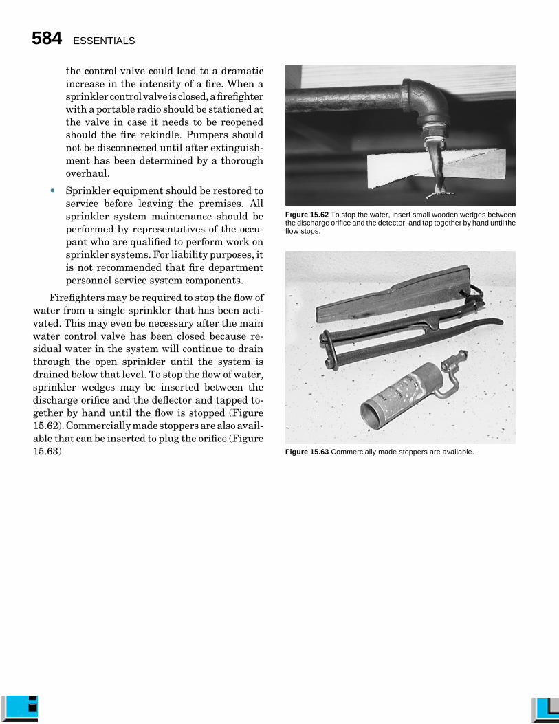
Firefighters may be required to stop the flow ofwater from a single sprinkler that has been acti-vated. This may even be necessary after the mainwater control valve has been closed because re-sidual water in the system will continue to drainthrough the open sprinkler until the system isdrained below that level. To stop the flow of water,sprinkler wedges may be inserted between thedischarge orifice and the deflector and tapped to-gether by hand until the flow is stopped (Figure15.62). Commercially made stoppers are also avail-able that can be inserted to plug the orifice (Figure15.63).
Figure 15.62 To stop the water, insert small wooden wedges betweenthe discharge orifice and the detector, and tap together by hand until theflow stops.
Figure 15.63 Commercially made stoppers are available.